

Endress+Hauser cerabar M PMP 46, cerabar M PMP 48 Technical Information
Technical
Information
TI322P/00/en
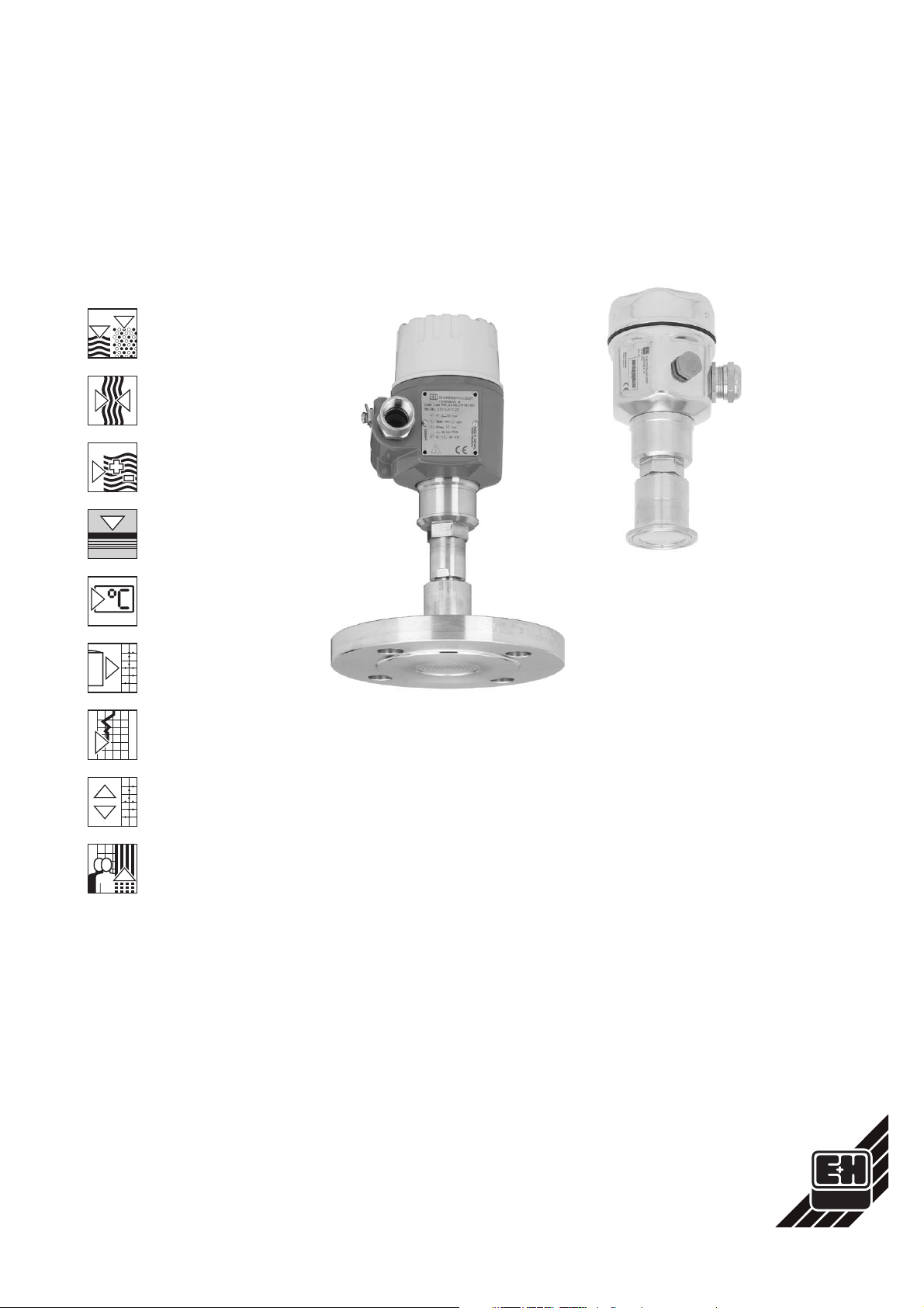
Pressure Transmitter
cerabar M PMP 46
cerabar M PMP 48
Overload resistant pressure transmitter with
diaphragm seal and analogue, Smart or
PROFIBUS-PA electronics
PMP 46
Clamp
PMP 48
Flange
Applications
The Cerabar M transmitter measures the
gauge and absolute pressure of gases,
vapours and liquids and can be used in
all areas of industry.
Installation and process conditions often
make the use of diaphragm seals
necessary. Endress+Hauser offers you
the following:
•
PMP 46: diaphragm seals for hygienic
applications
•
PMP 48: diaphragm seals with
threaded boss, separator, flange or
flange with extension
Features and Benefits
•
Accuracy
− Linearity better than 0.2% of set span
− Adjustable measuring range with
TD 10:1
− Long-term stability better than 0.1%
•
Piezoresistive metal sensor with metal
diaphragm for measuring ranges up to
400 bar (6000 psi).
•
Electronics
− Analogue: cost effective version with
short response time especially for
fast processes
− Smart: intelligent with versatile
operating procedures via HART
protocol
− PROFIBUS-PA: tried and tested for
digital communications
•
Housing
With its stainless steel housing and no
dead volume, the Cerabar M fulfils all
the special hygienic requirements of
the food and pharmaceutical
industries. The polyester-epoxy
coated aluminium housing has proven
itself well in the process industry.
•
Process connections
All customary thread versions,
hygienic connections and flanges
available.
Endress
The Power of Know How
+
Hauser
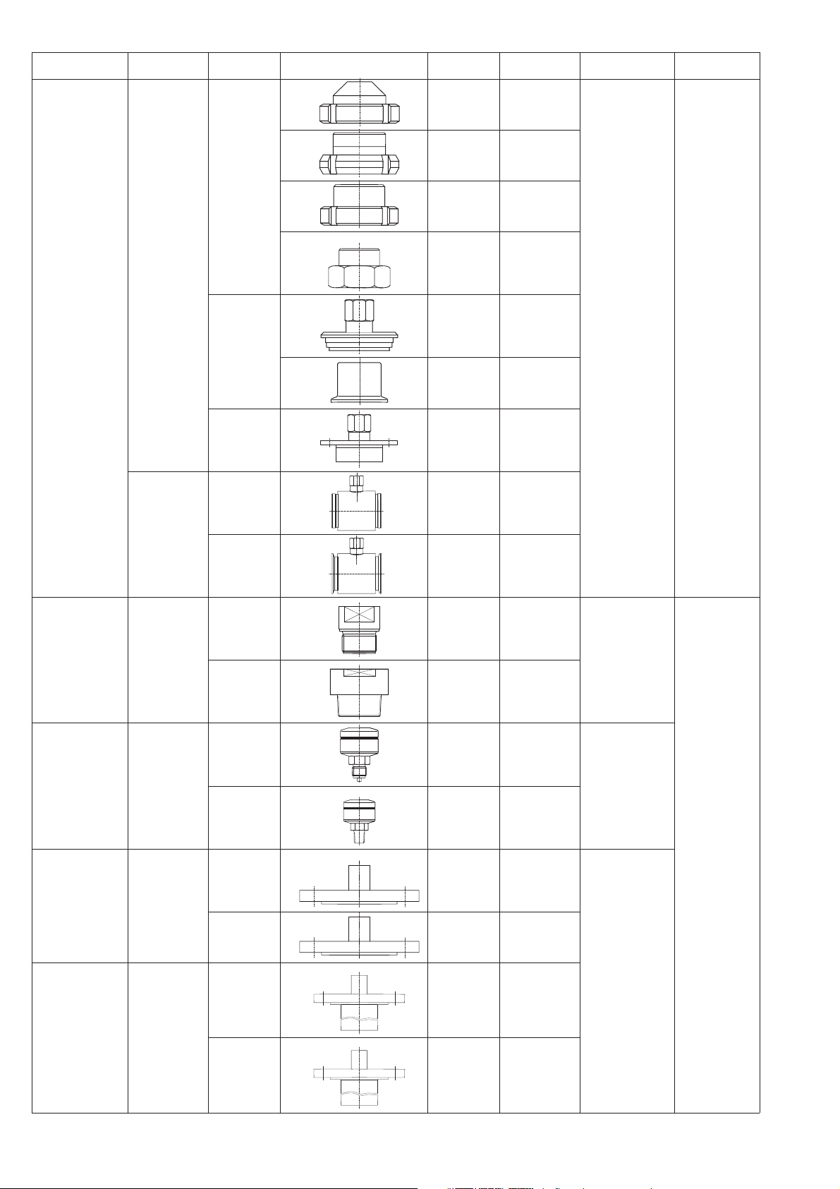
Construction Diaphragm
Hygienic
applications
seal
Diaphragm
seal
Connection Page/Version Standard Nominal width Pressure
Groove nut Page 21 DIN 11851 DN 32,
DN 40,
DN 50
Page 23 SMS 1½", 2"
Page 23 RJT 1½", 2"
Page 23 ISS 1½", 2"
range
max. 40 bar
(600 psi)
Instrument type
PMP 46
Threaded boss
Pipe
diaphragm
seal
Diaphragm
seal
Clamping
bracket
Flange Page 24 DRD D = 65 mm
Thread
adapter
Clamping
bracket
G Page 27 DIN ISO
NPT Page 27 ANSI
Page 24 Varivent Type N
Page 22 Clamp 1½", 2", 3"
Page 21 DIN 11851 DN 25,
Page 22 Clamp ¾", 1", 1½", 2"
228/1
B1.20.1
DN 40,
DN 50
G 1
G 1½
G 2
1 NPT
1½ NPT
2 NPT
max. 400 bar
(6000 psi)
PMP 48
Threaded boss
with separator
Flange
Flange with
extension
Diaphragm
seal
Diaphragm
seal
Diaphragm
seal
G Page 28 EN 837 G ½ max. 160 bar
NPT Page 28 ANSI
DIN
flange
ANSI
flange
DIN
flange
ANSI
flange
Page 29 DIN 2501 DN 25
Page 30 ANSI B.16.5 1", 2", 3", 4"
Page 29 DIN 2501 DN 50
Page 30 ANSI B.16.5 2", 3", 4"
B1.20.1
½ NPT
DN 50
DN 80
DN 80
(2300 psi)
max. 400 bar
(6000 psi)
2

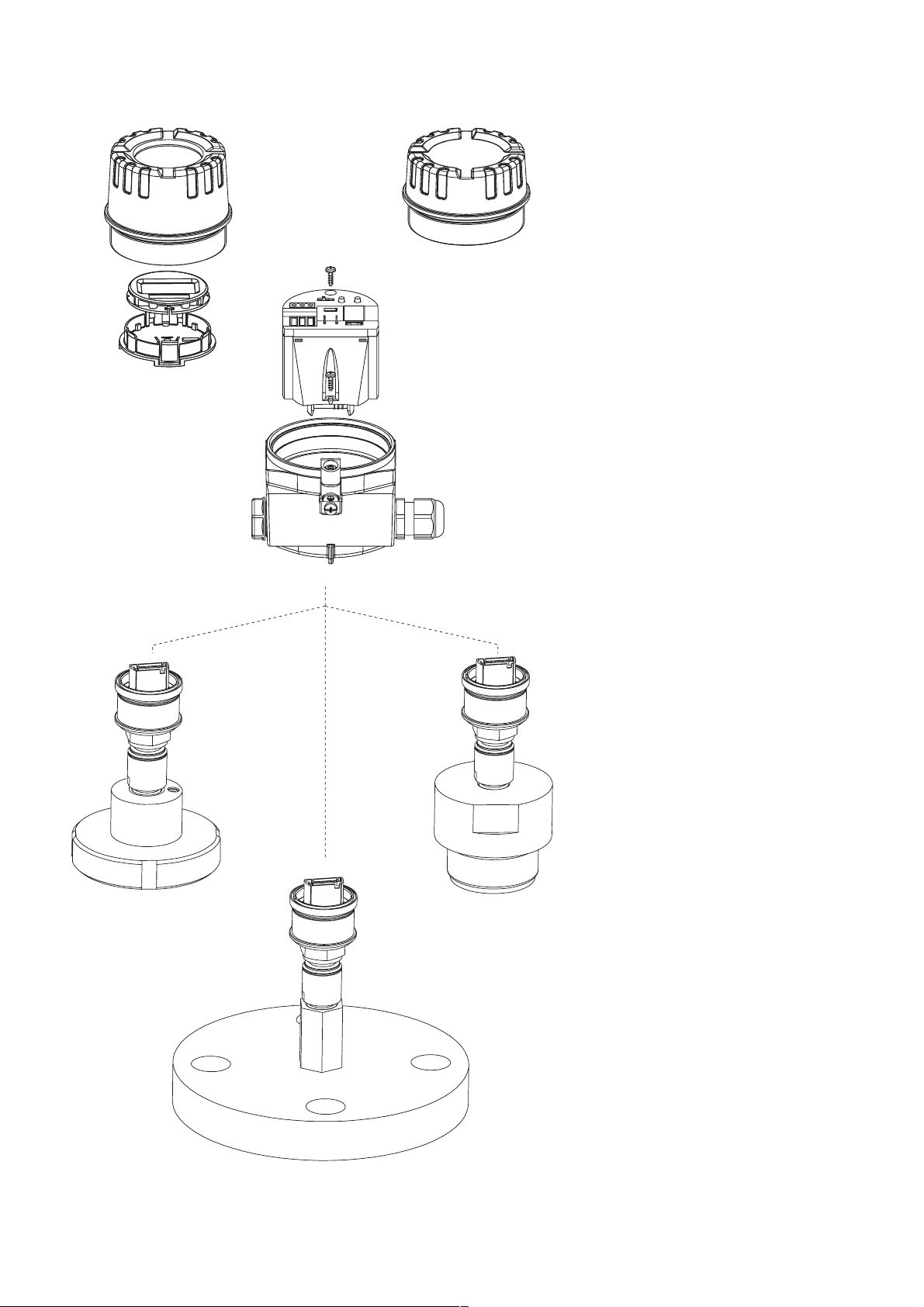
Instrument Configuration of Cerabar M with Stainless Steel Housing
Housings
The stainless steel housing of Cerabar M
is especially remarkable due to its
chemical resistance and hygienic
properties. Having no dead volume and
being condensation-tight with a surface
roughness of Ra ≤ 0,8 µm, it is easy to
clean and thereby ideal for the food and
pharmaceutical industry.
The aluminium housing has proven its
ruggedness and has become a
standard in many industries such as
chemicals, papermaking, power
generation, water and wastewater
treatment.
•
Ingress protection
− IP 65 with Harting plug (Han7D),
− IP 66/Nema 4X as standard or
− IP 68/Nema 6P with 5 m (16.4 ft)
assembled cable with pressure
compensation or plug M 12x1.
This version is recommended for
very moist applications (e.g. wet
vessel walls or pipes).
•
Optional connection with
− cable gland M 20x1.5 or
− cable entry ½ NPT or G ½,
− Harting plug (Han7D) or
plug M 12x1 or
− with assembled cable
•
A raised cover with sight glass is
provided when using a display. A low
cover is available for versions without
a local display.
display
holder for
display
process connection
PMP 46
e.g. with dairy
thread connection
with sight glass
low coverraised cover
for display
electronic insert
housing
process connection
PMP 48
e.g. with G 2 A thread
process connection
PMP 48
e.g. flange
Electronic Inserts
Cerabar M has three electronics versions
•
Analogue: 4…20 mA
Operation directly at the measuring
point with one potentiometer each for
lower range-value and upper
range-value and a three-step range
switch as well as an on/off switch for
damping.
•
Smart: 4…20 mA with HART protocol
Operation:
− at the measuring point via two push
buttons for lower range-value and
upper range-value as well as an
on/off switch for damping, or
− via the Universal HART Communicator
DXR 275 handheld terminal at any
point along the 4…20 mA line, or
− via PC e.g. with the Endress+Hauser
Commuwin II operating program.
•
PROFIBUS-PA:
Operation:
– Using a PC with an operating
program, e.g. Commuwin II from
Endress+Hauser, or
– using two keys for lower range-value
and upper range-value.
3
Instrument Configuration of Cerabar M with Aluminium Housing
Displays
A display module can be used for
showing measured values and for
simplifying local operation. The display
is plugged onto the electronic insert
using a holder.
•
Analogue display for Cerabar M with
analogue electronics: The analogue
display gives the current pressure
value related to the measuring range
in the form of a bar graph.
•
Digital display for Cerabar M with
Smart electronics: The digital display
gives the pressure in the form of a
four-digit number. The appropriate
current value from 4…20 mA is shown
as a bar graph underneath.
•
Digital display for Cerabar M with
PROFIBUS-PA electronics:
The digital display gives the pressure
in the form of a four-digit number. The
bar graph depicts the current pressure
value related to the measuring range.
Process Connections
•
Process connections are available
with all common threads,
flush-mounted hygienic connections
and flanges (see summary, page 2).
•
Chemical resistance can be
guaranteed by selecting suitable
materials for the process connection.
This applies especially to the metal
separating diaphragm of the
diaphragm seal in contact with the
medium.
•
The diaphragm is welded to every
diaphragm seal with no dead volume.
display
holder for
display
process connection
PMP 46
e.g. with dairy
thread connection
raised cover
with sight glass
for display
low cover
electronic insert
housing
process connection
PMP 48
e.g. with G 2 A thread
process connection
PMP 48
e.g. flange
4
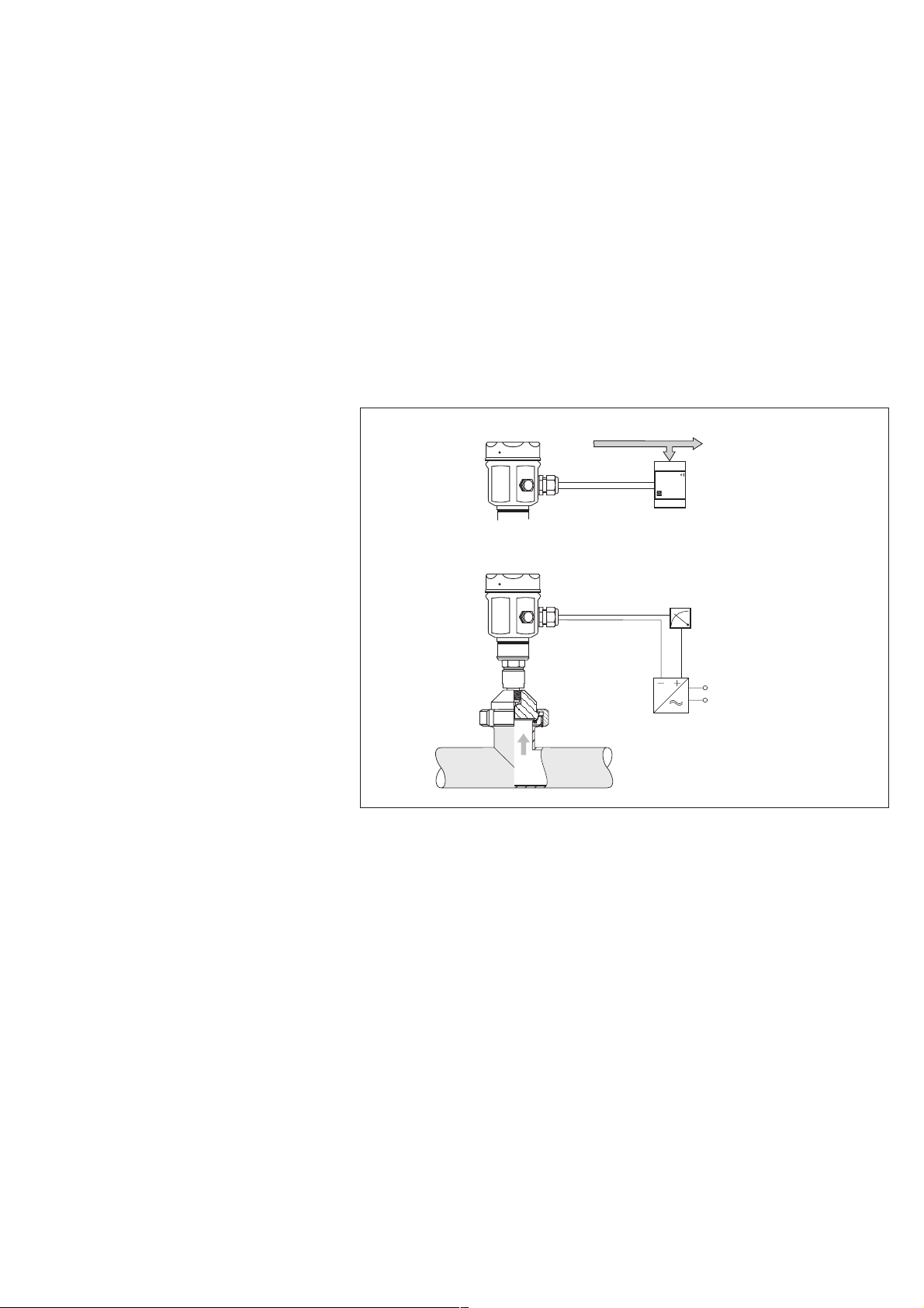
Measuring System
System Components
The complete measuring system
consists of:
•
Cerabar M pressure transmitter with
− analogue output 4…20 mA and
− supply voltage, e.g. with the
RN 221N transmitter power supply
unit from Endress+Hauser
Supply voltage: 11.5…45 V DC
Cerabar M
PROFIBUS-DP
PROFIBUS-PA
or
•
Cerabar M pressure transmitter with
− 4…20 mA signal output and HART
communication signal and
− supply voltage, e.g. RN 221N
transmitter power supply unit from
Endress+Hauser
Supply voltage: 11.5…45 V DC
or Ex ia: 11.5…30 V DC
or
•
Cerabar M pressure transmitter with
− PROFIBUS-PA digital communication
signal and
− connection via segment coupler to a
PLC or PC using e.g. the
Endress+Hauser Commuwin II
operating program
Supply voltage: 9…32 V DC
or Ex ia: 9…24 V DC
via segment coupler
connection to
ENDRESS+ HAUSER
PLC or PC
Complete measuring
system Cerabar M
above:
with PROFIBUS-PA
electronics
below:
with Smart electronics or
with analogue electronics
Cerabar M
4…20 mA
Supply voltage
(e.g. with RN 221N):
11.5…45 V DC
for Ex ia (Smart electronics only):
11.5…30 V DC
5
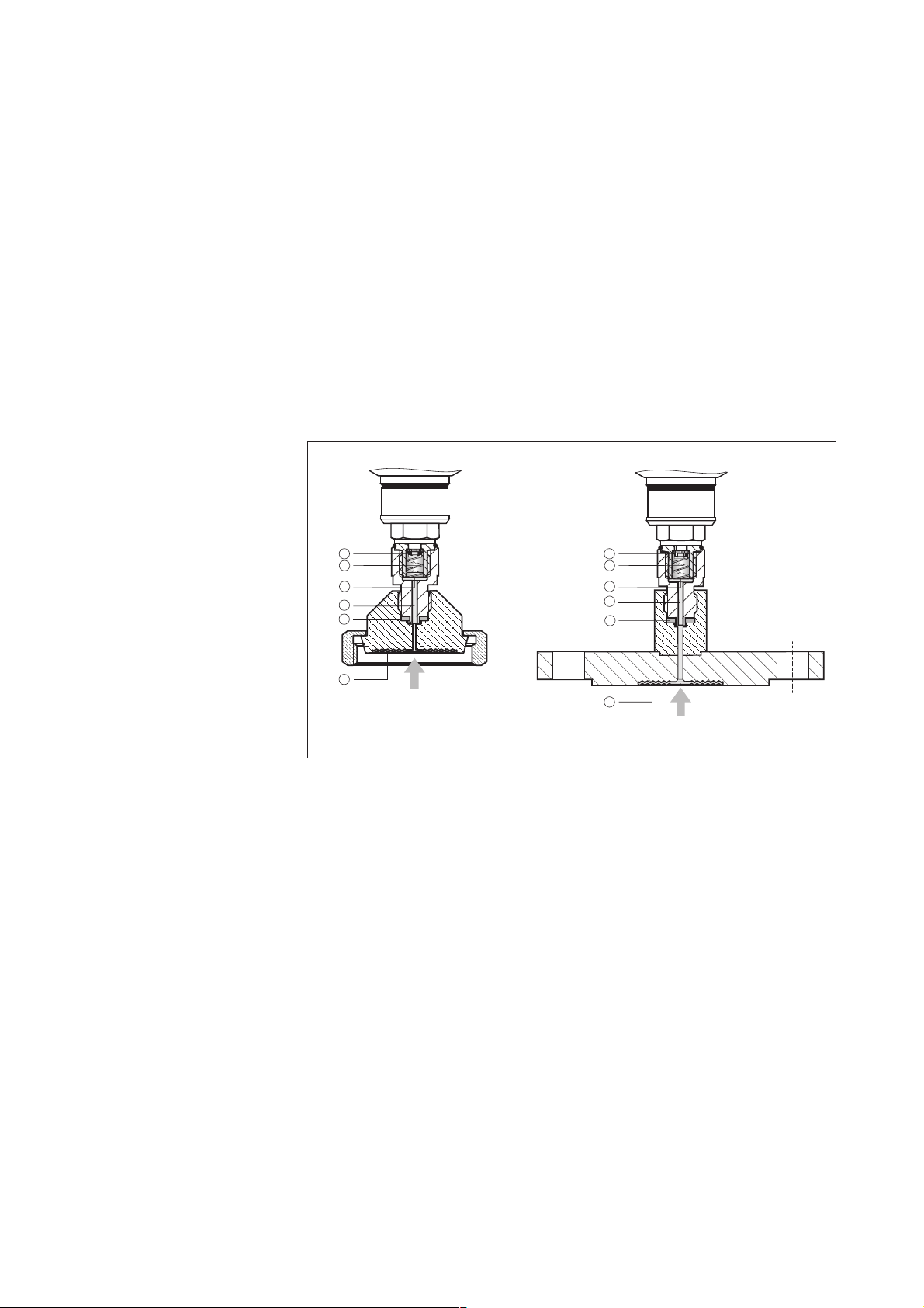
Operating Principle
Piezoresistive Sensor with
Diaphragm Seal
The process pressure acting on the
diaphragm of the diaphragm seal is
transmitted to the metallic separating
diaphragm of the sensor by the filling
fluid of the diaphragm seal. The
separating diaphragm is deflected and
the fluid transmits the pressure to a
resistance bridge. The bridge output
voltage, which is proportional to
pressure, is then measured and
evaluated.
Advantages:
•
For process pressures up to 400 bar
(6000 psi)
•
Excellent long-term stability
•
Guaranteed resistance to overload up
to 4-times nominal pressure
(max. 600 bar/9000 psi)
➀ Diaphragm of
diaphragm seal
➁ Copper ring
➂ Diaphragm seal filling
fluid
➃ Metallic
separation diaphragm
➄ Channel with
filling fluid
➅ Polysilicone
measuring element
6
5
4
3
2
1
process pressure
6
5
4
3
2
1
process pressure
6
Operation
Three electronics versions are available
for operating the Cerabar M.
•
The analogue electronics is the
simplest and most cost-effective
method to operate the Cerabar M.
•
Smart electronics opens up a wide
range of operating and calibration
routines. It can then be operated
either by means of a handheld
terminal or an operating program (e.g.
Endress+Hauser Commuwin II).
•
The PROFIBUS-PA electronics provide
direct connection to the PROFIBUS-PA
field bus. The PROFIBUS-PA can be
easily set up and many values are
retrievable from the control room.
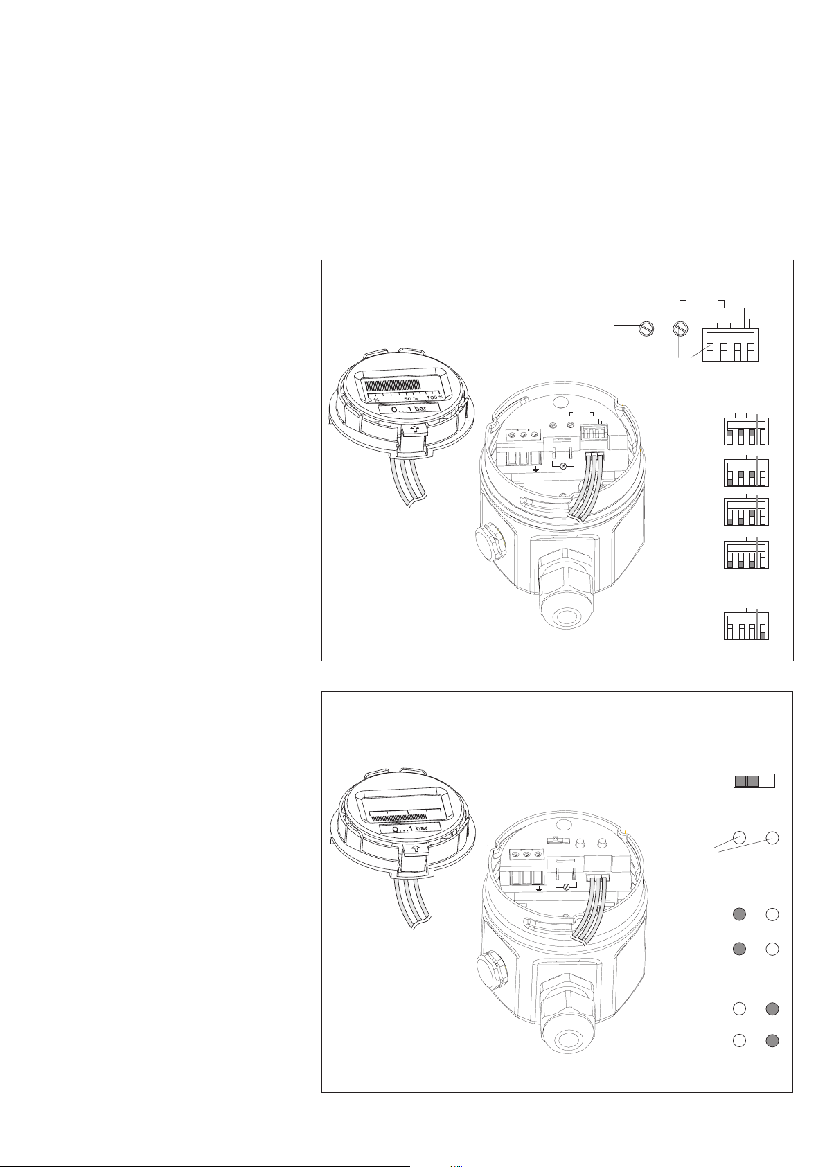
Analogue Electronics
For the Cerabar M with analogue
electronics lower range-value (Zero)
and upper range-value (Span) are
directly calibrated at the measuring
point via two potentiometers. The
required lower and upper range-values
must be applied as reference pressure.
•
For coarse calibration of the
measuring span, a spread between
TD 1:1 and TD 10:1 can be selected
using DIP switches.
•
A 2 s damping of the measured value
can be activated using a DIP switch.
•
The analogue display shows the
pressure on a bar graph as a ratio to
the measuring range.
•
Over- or under-run of the signal can
be indicated by a flashing of the bar
graph.
Analogue display
(optional)
Potentiometer for
calibrating the
lower range-value
Zero
3
2
1
–
+
Operating elements
Zero
Potentiometer and switches
for calibrating the upper range-value
Span
coarse
τ
fine
123
Display
Switch position “on”
Damping = 2 s activated
Span
fine coarse τ
Coarse adjustment
for upper range-value
TD 1:1
TD 3:1
TD 6:1
TD 10:1
TD: turn down
1
23
1
23
1
23
1
23
1
23
Damping switch
1
23
off
on
τ
off
on
τ
off
on
τ
off
on
τ
off
on
τ
off
on
Smart Electronics
A Cerabar M with Smart electronics can
be calibrated with or without reference
pressure.
– When calibrating with reference
pressure, the pressure for lower
range-value and upper range-value
must be entered and confirmed by
pressing the Zero or Span key twice.
Press these keys once to display saved
values for lower range-value and upper
range-value.
– If you calibrate without reference
pressure, enter the measuring points
using a handheld terminal or using an
operating program.
•
A damping of 2 s can be set directly
on the instrument. A damping value of
0...40 s can be selected using
communication.
•
The digital display shows the pressure
as a four-character number. The
appropriate 4…20 mA current is
shown as a bar graph underneath.
•
Error codes on the digital display and
in Commuwin II simplify error
diagnosis.
Digital display
(optional)
0,753
12+–3
Damping
on off
Zero
Span
Display
Operating elements
Switch position "on"
Damping = 2 s activated
Zero
Keys for
calibrating the
lower rangevalue
and upper
range-value
1x
2x
1x
2x
Damping
off
on
Span
Lower rangevalue:
Display
Registration
Upper rangevalue:
Display
Registration
7
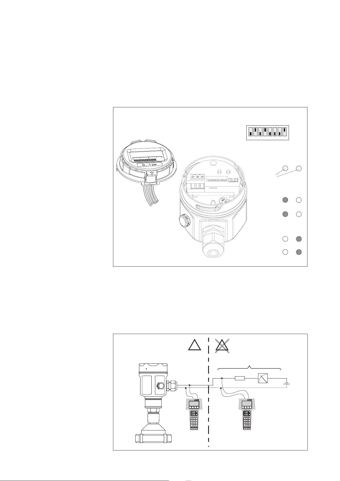
PROFIBUS-PA Electronics
A Cerabar M with PROFIBUS-PA
electronics has the following operating
options.
•
You can set a damping of between 0
and 40 s using communication.
•
You can set instrument bus address
direct in the instrument using the
address switch.
Digital display
(optional)
0,753
123
•
The digital display gives the pressure
as a four-digit number. The bar graph
depicts the current pressure value
related to the measuring range. The
measuring range can be set either on
site using the Zero and Span keys or
remotely using an operating program,
such as Commuwin II.
•
Error codes on the digital display and
in Commuwin II simplify error
diagnosis.
Operating elements
16 32 64
28
5678
1x
2x
1x
2x
on
off
Zero
address
Span
Display
14
1234
DIP switches to set
bus address
Keys for
calibrating the
lower rangevalue
and upper
range-value
SW
HW
Value
ON
OFF
Switch No.
Zero
Span
Lower rangevalue:
Display
Registration
Upper rangevalue:
Display
Registration
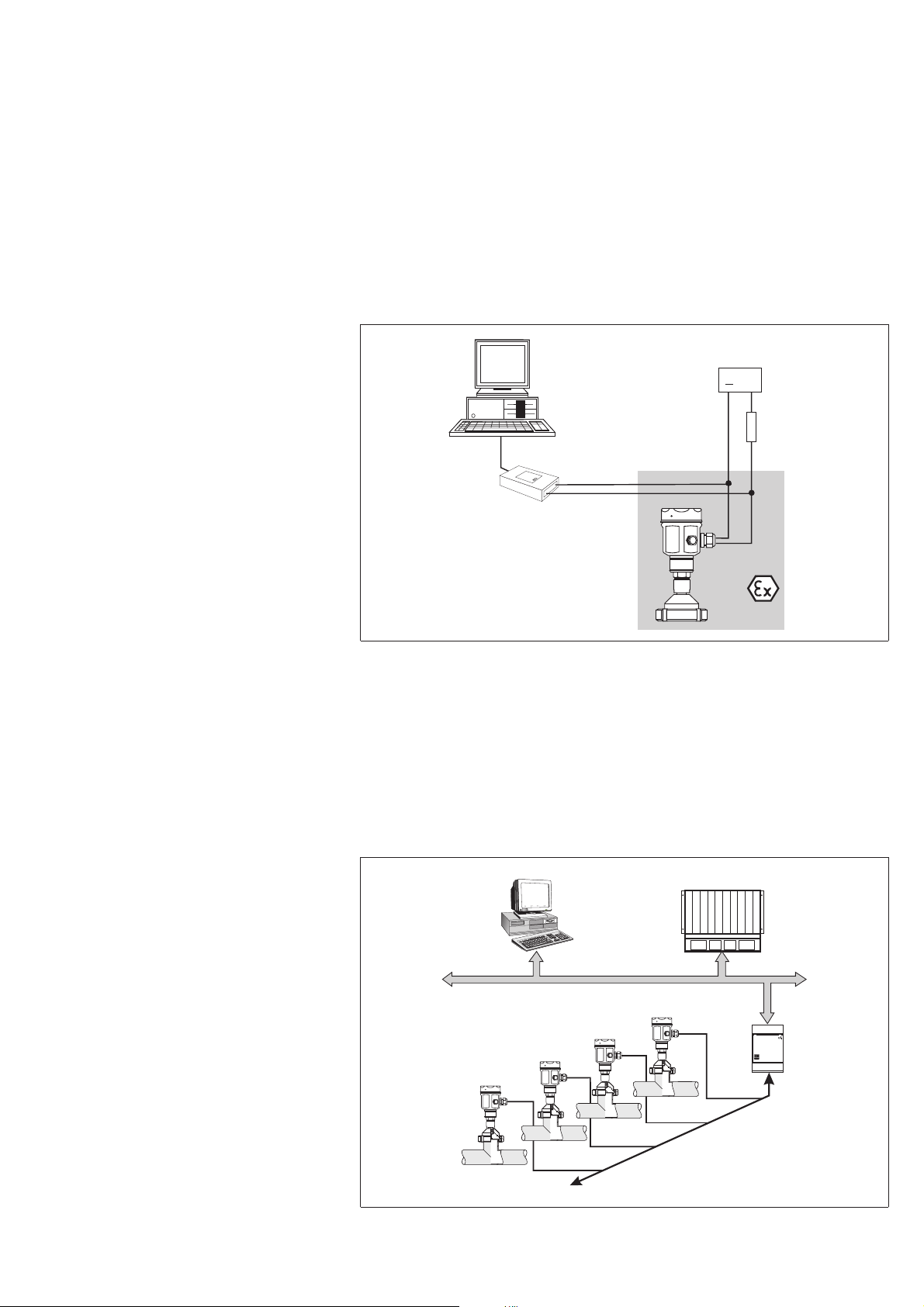
Cerabar M
operation with Smart
electronics using a
handheld terminal
Smart Electronics Operation Using a
Handheld Terminal
Using the Universal HART
Communicator DXR 275 handheld
terminal, you can set the Cerabar M,
make checks and use additional
functions such as "Damping" and
"Calibration without reference pressure"
all along the 4...20 mA line.
EX
Cerabar M
I
O
EX
minimum line resistance
250 Ω
R
4...20 mA
I
O
Universal HART Comunicator
DXR 275
*
* Use an
intrinsically
safe supply
voltage for Ex i
(e.g. RN 221 N)
8
Smart Electronics Operation Using
PC
The Commubox FXA 191 connects
4…20 mA Smart transmitters that have a
HART protocol to the RS 232 C serial
interface of a personal computer. This
enables the transmitter to be remotely
operated with the Endress+Hauser
Commuwin II operating program.
You can connect the Commubox
FXA 191 at any point along the
4…20 mA line. It is also suited for
connection to intrinsically-safe signal
circuits.
Cerabar M
operation with Smart
electronics using PC
PC with
operating program
e.g. Commuwin II
Commubox
FXA 191
Cerabar M
Connecting to PROFIBUS-PA
PROFIBUS-PA is an open fieldbus
standard to enable serveral sensors and
actuators, including those in
explosion-hazardous areas, to be
connected to bus line. With
PROFIBUS-PA, two-wire looped
instruments can be supplied by the
sensor with power and digital process
information.
supply voltage
+
minimum line
resistance
250 Ω
4…20 mA
The number of instruments operated by
one bus segment is:
•
up to 10 for Ex ia applications
•
up to 32 for all further applications
(e.g. non-Ex, EEx nA)
Cerabar M
operation with
PROFIBUS-PA
electronics
Cerabar M
pressure transmitters
9
PC with
operating program
e.g. Commuwin II
PROFIBUS-DP
Fieldbus with
PROFIBUS-PA
PLC
segment coupler
ENDRESS+ HAUSER
Installation
Mounting Instructions
•
The protective cap of the diaphragm
seal should only be removed just
before mounting.
•
The diaphragm seal and the pressure
sensor together form a closed,
oil-filled, calibrated system. The
following rules should be observed:
− The filling hole is sealed and not to
be opened.
− When mounting the Cerabar M, it
should only be turned by the nut of
the diaphragm seal and not by the
hex nut of the Cerabar M.
Cleaning
The diaphragm of the diaphragm seal
must not be pressed in or cleaned with
pointed or hard objects.
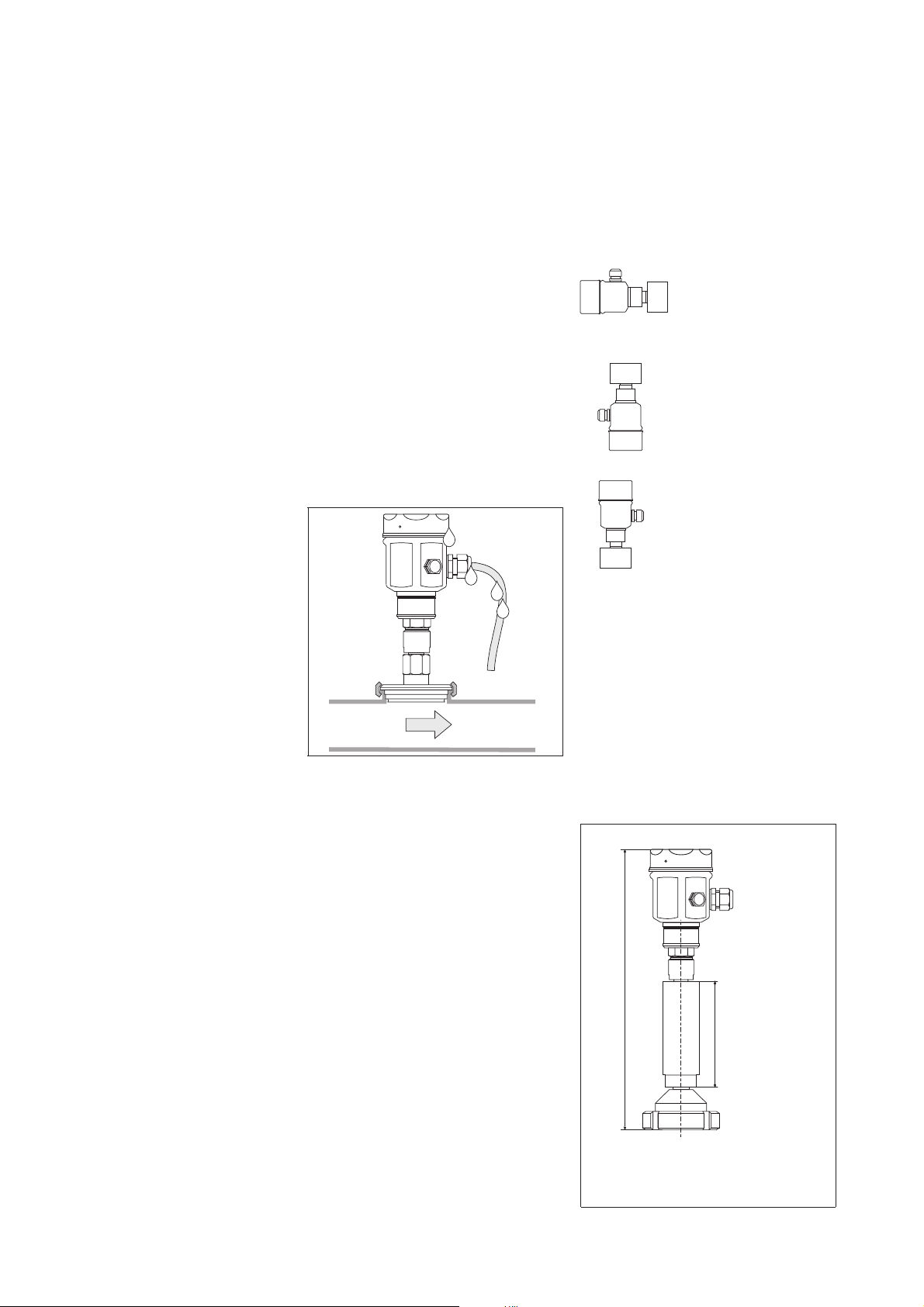
Mounting
To prevent moisture from entering, the
cable entry should preferably hang
downwards or to the side.
Shifting of the Zero Point due to
Position
The Cerabar M is calibrated based on
the limit point method according to
DIN 16086.
Depending on the orientation of the
instrument, there may be a slight shift in
the measured value. Diaphragm seals
also shift the zero point depending on
the orientation of the instrument.
•
neutral calibration position
•
max. positive zero point shift
•
max. negative zero point shift
vertical
mounting
cable points
downwards
Mounting with Temperature Spacer
Endress+Hauser recommends the use
of a temperature spacer when extreme
media temperatures (from approx.
150°C/302°F) continually cause the
ambient temperature to exceed the
permissible limit of +85°C (+185°F).
This zero point shift due to position can
be corrected (refer to zero point
increase and decrease, page 16).
The max. effect of position for all
diaphragm seals is given in the tables
on page 21 onwards. These values are
for silicone oil. For other oils available,
the shift in zero point due to position
varies according to the density of the oil
(see page 12).
Cerabar M with
temperature spacer
10
*
m
(3.94 in)
100 m
Information on the maximum installation
height is given on page 21 onwards
* Additional zero point shift
caused by the hydrostatic
pressure of the water column
in the temperature spacer:
10 mbar (0.15 psi)
 Loading...