

Page 1
BA01773C/07/EN/02.19
71431040
2019-02-08
Products Solutions Services
Operating Instructions
CCS50D
Digital sensor with Memosens technology for
determining chlorine dioxide
Page 2

Page 3

CCS50D Table of contents
Table of contents
1 About this document ........... 4
1.1 Warnings ........................... 4
1.2 Symbols used ........................ 4
11 Accessories .................... 40
11.1 Maintenance kit CCV05 .............. 40
11.2 Device-specific accessories ............ 40
2 Basic safety instructions ....... 6
2.1 Requirements for the personnel ........ 6
2.2 Designated use ...................... 6
2.3 Workplace safety .................... 6
2.4 Operational safety ................... 7
2.5 Product safety ....................... 7
3 Product description ............. 8
3.1 Product design ....................... 8
4 Incoming acceptance and
product identification ......... 13
4.1 Incoming acceptance ................ 13
4.2 Product identification ................ 13
5 Installation .................... 15
5.1 Installation conditions ............... 15
5.2 Mounting the sensor ................ 17
5.3 Post-installation check ............... 24
6 Electrical connection .......... 25
6.1 Connecting the sensor ............... 25
6.2 Ensuring the degree of protection ..... 25
6.3 Post-connection check ............... 26
7 Commissioning ................ 27
7.1 Function check ..................... 27
7.2 Sensor polarization .................. 27
7.3 Sensor calibration ................... 27
12 Technical data ................. 41
12.1 Input .............................. 41
12.2 Performance characteristics .......... 43
12.3 Environment ....................... 44
12.4 Process ............................ 44
12.5 Mechanical construction ............. 45
13 Installation and operation in
hazardous environment Class
I Div. 2 .......................... 46
Index ................................. 48
8 Diagnostics and
troubleshooting ............... 29
9 Maintenance .................. 31
9.1 Maintenance schedule ............... 31
9.2 Maintenance tasks .................. 32
10 Repair .......................... 39
10.1 Spare parts ........................ 39
10.2 Return ............................ 39
10.3 Disposal ........................... 39
Endress+Hauser 3
Page 4
About this document CCS50D
1 About this document
1.1 Warnings
Structure of information Meaning
DANGER
L
Causes (/consequences)
If necessary, Consequences of noncompliance (if applicable)
Corrective action
‣
WARNING
L
Causes (/consequences)
If necessary, Consequences of noncompliance (if applicable)
Corrective action
‣
CAUTION
L
Causes (/consequences)
If necessary, Consequences of noncompliance (if applicable)
Corrective action
‣
NOTICE
Cause/situation
If necessary, Consequences of noncompliance (if applicable)
Action/note
‣
This symbol alerts you to a dangerous situation.
Failure to avoid the dangerous situation will result in a fatal or serious injury.
This symbol alerts you to a dangerous situation.
Failure to avoid the dangerous situation can result in a fatal or serious injury.
This symbol alerts you to a dangerous situation.
Failure to avoid this situation can result in minor or more serious injuries.
This symbol alerts you to situations which may result in damage to property.
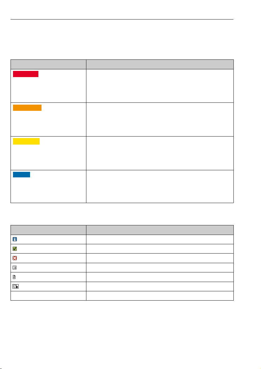
1.2 Symbols used
Symbol Meaning
Additional information, tips
Permitted or recommended
Not permitted or not recommended
Reference to device documentation
Reference to page
Reference to graphic
Result of a step
4 Endress+Hauser
Page 5

CCS50D About this document
1.2.1 Symbols on the device
Symbol Meaning
Reference to device documentation
Endress+Hauser 5
Page 6

Basic safety instructions CCS50D
2 Basic safety instructions
2.1 Requirements for the personnel
Installation, commissioning, operation and maintenance of the measuring system may be
carried out only by specially trained technical personnel.
The technical personnel must be authorized by the plant operator to carry out the specified
‣
activities.
The electrical connection may be performed only by an electrical technician.
‣
The technical personnel must have read and understood these Operating Instructions and
‣
must follow the instructions contained therein.
Measuring point faults may be repaired only by authorized and specially trained personnel.
‣
Repairs not described in the Operating Instructions provided must be carried out only
directly at the manufacturer's site or by the service organization.
2.2 Designated use
Drinking water and industrial water must be disinfected through the addition of appropriate
disinfectants such as chlorine gas or inorganic chlorine compounds. The dosing quantity must
be adapted to continuously fluctuating operating conditions. If the concentrations in the water
are too low, this could jeopardize the effectiveness of the disinfection. On the other hand,
concentrations which are too high can lead to signs of corrosion and have an adverse effect on
taste, as well as generating unnecessary costs.
The sensor was specifically developed for this application and is designed for continuous
measurement of chlorine dioxide in water. In conjunction with measuring and control
equipment, it allows optimal control of disinfection.
Use of the device for any purpose other than that described, poses a threat to the safety of
people and of the entire measuring system and is therefore not permitted.
The manufacturer is not liable for damage caused by improper or non-designated use.
2.2.1
1. The device must be installed in a housing or cabinet that can be accessed only by means
2. Pay attention to the control drawing and the specified application conditions in the
Hazardous environment in accordance with cCSAus NI Cl. I, Div. 2
of a tool or key.
appendix of these Operating Instructions, and follow the instructions.
1)
2.3 Workplace safety
As the user, you are responsible for complying with the following safety conditions:
• Installation guidelines
• Local standards and regulations
1) Only if connected to CM44x(R)-CD*
6 Endress+Hauser
Page 7

CCS50D Basic safety instructions
Electromagnetic compatibility
• The product has been tested for electromagnetic compatibility in accordance with the
applicable European standards for industrial applications.
• The electromagnetic compatibility indicated applies only to a product that has been
connected in accordance with these Operating Instructions.
2.4 Operational safety
Before commissioning the entire measuring point:
1. Verify that all connections are correct.
2. Ensure that electrical cables and hose connections are undamaged.
3. Do not operate damaged products, and protect them against unintentional operation.
4. Label damaged products as defective.
During operation:
If faults cannot be rectified:
‣
products must be taken out of service and protected against unintentional operation.
2.4.1 Special instructions
Do not operate the sensors under process conditions where it is expected that osmotic
‣
conditions will cause electrolyte components to pass through the membrane and into the
process.
Use of the sensor for its intended purpose in liquids with a conductivity of at least 10 nS/cm
can be classified as safe in terms of the application.
2.5 Product safety
The product is designed to meet state-of-the-art safety requirements, has been tested, and
left the factory in a condition in which it is safe to operate. The relevant regulations and
European standards have been observed.
Endress+Hauser 7
Page 8
Product description CCS50D
3
1
2
4
5
7
6
8
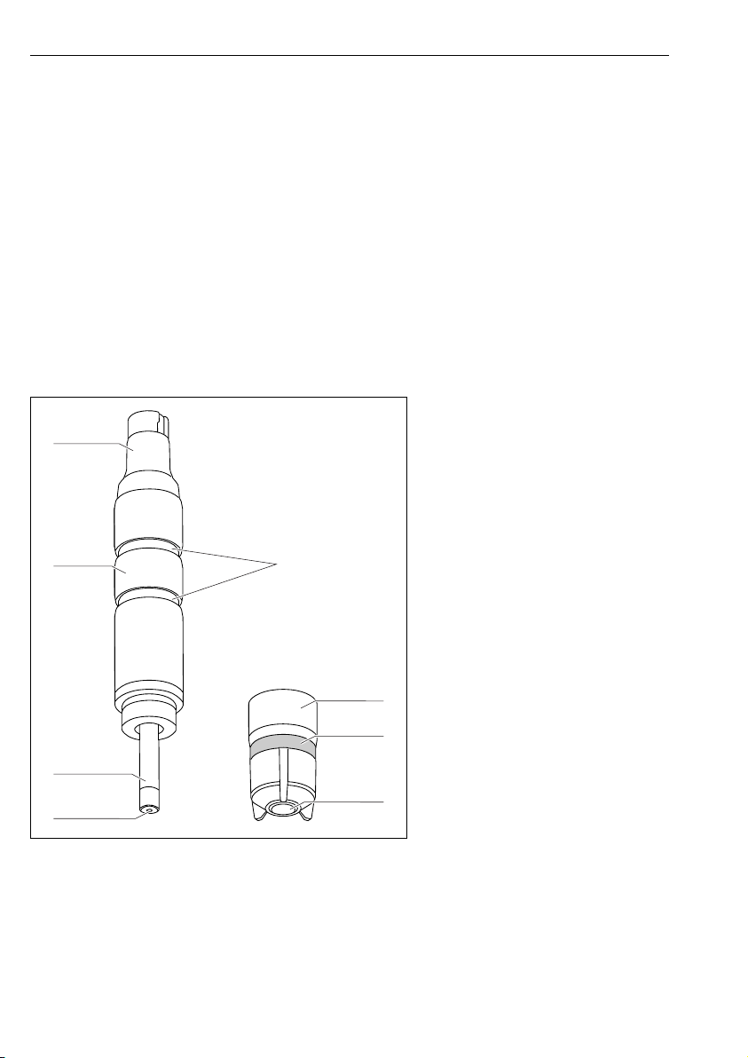
3 Product description
3.1 Product design
The sensor consists of the following functional units:
• Membrane cap (measuring chamber with membrane)
– Separates the inner amperometric system from the medium
– With robust PVDF membrane and pressure relief valve
– Guarantees a defined and consistent electrolyte film between cathode and membrane
– With special support grid between cathode and membrane for a defined and consistent
electrolyte film and therefore a relatively constant reading at varying pressures and flows
• Sensor shaft with
– Large anode
– Cathode embedded in plastic
– Embedded temperature sensor
1 Memosens plug-in head
2 Sensor shaft
3 Large anode, silver/silver chloride
4 Gold cathode
5 Grooves for installation adapter
6 Membrane cap with dirt-repellent
membrane
7 Pressure relief valve (elastic)
8 Sensor membrane
1 Sensor structure
A0034227
3.1.1 Measuring principle
Chlorine dioxide levels are determined in accordance with the amperometric measuring
principle.
The chlorine dioxide (ClO2) in the medium diffuses through the sensor membrane and is
reduced to chloride ions (Cl-) at the gold cathode. At the silver anode, silver is oxidized to
8 Endress+Hauser
Page 9

CCS50D Product description
silver chloride. Electron donation at the gold cathode and electron acceptance at the silver
anode cause a current to flow which is proportional to the concentration of chlorine dioxide in
the medium. This process does not depend on the pH value over a wide range.
The transmitter uses the current signal to calculate the measured variable for concentration in
mg/l (ppm).
3.1.2 Effects on the measured signal
pH value
pH dependency
pH value Result
< 3.5 Chlorine is produced if chloride (Cl-) is present in the medium at the same time. The strong cross-sensitivity
3.5 to 9 The pH value does not affect measurement of the chlorine dioxide concentration in the medium.
> 9 Chlorine dioxide is unstable and decomposes.
to chlorine dioxide causes an increase in the measured value.
Flow
The minimum flow velocity of the membrane-covered measuring cell is 15 cm/s (0.5 ft/s).
• When using the Flowfit CCA151 flow assembly, this corresponds to a flow rate of
5 l/h (1.3 gal/h).
• When using the CCA250 flow assembly, this corresponds to a flow rate of
30 l/h (7.9 gal/h) (upper edge of float at the height of the red bar mark).
Endress+Hauser 9
Page 10
Product description CCS50D
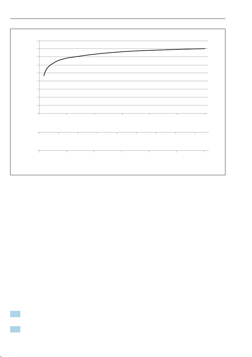
80
90
100
relative slope / maximum slope in %
CCA151 flow gal/hr
CCA250 flow gal/hr
flow velocity at the membrane "/s
0 0.5 1 1.5 2 3
0 5 10 25 40
0
1
2 3 4 5 6
2.5
15
20
30 35
A0034487-EN
2 Correlation between slope of electrode and flow velocity at the membrane/flow rate in assembly
At higher flow rates, the measured signal is virtually flow-independent. However, if the flow
rate falls below the specified value, the measured signal depends on the flow.
The installation of an INS proximity switch in the assembly enables reliable detection of this
invalid operating status, thus triggering an alarm or causing the dosing process to be switched
off if necessary.
Below the minimum flow rate, the sensor current is more sensitive to flow fluctuations. For
abrasive media, it is recommended not to exceed the minimum flow. If suspended solids are
present, which may form deposits, the maximum flow rate is recommended.
Temperature
Changes in the temperature of the medium affect the measured value:
• Increases in temperature result in a higher measured value (approx. 4 % per K)
• Decreases in temperature result in a lower measured value.
Use of the sensor in combination with the Liquiline enables automatic temperature
compensation (ATC). Recalibration in the case of temperature changes is not necessary.
1. If automatic temperature compensation is disabled at the transmitter, the temperature
must be maintained at a constant level following calibration.
2. Otherwise, recalibrate the sensor.
10 Endress+Hauser
Page 11

CCS50D Product description
In the event of normal and slow changes in temperature (0.3 K / minute), the internal
temperature sensor is sufficient. In the event of very rapid temperature fluctuations with high
amplitude (2 K / minute), an external temperature sensor is necessary to ensure maximum
accuracy.
For detailed information on the use of external temperature sensors, see the Operating
Instructions for the transmitter.
Endress+Hauser 11
Page 12

Product description CCS50D
Cross-sensitivities
2)
Free chlorine, ozone, free bromine
There were no cross-sensitivities for: H2O2, peracetic acid
2) The listed substances have been tested with different concentrations. An additive effect has not been
investigated.
12 Endress+Hauser
Page 13

CCS50D Incoming acceptance and product identification
4 Incoming acceptance and product identification
4.1 Incoming acceptance
1. Verify that the packaging is undamaged.
Notify the supplier of any damage to the packaging.
Keep the damaged packaging until the issue has been resolved.
2. Verify that the contents are undamaged.
Notify the supplier of any damage to the delivery contents.
Keep the damaged goods until the issue has been resolved.
3. Check that the delivery is complete and nothing is missing.
Compare the shipping documents with your order.
4. Pack the product for storage and transportation in such a way that it is protected
against impact and moisture.
The original packaging offers the best protection.
Make sure to comply with the permitted ambient conditions.
If you have any questions, please contact your supplier or your local Sales Center.
4.2 Product identification
4.2.1 Nameplate
The nameplate provides you with the following information on your device:
• Manufacturer identification
• Extended order code
• Serial number
• Safety information and warnings
Compare the information on the nameplate with the order.
‣
4.2.2 Product page
www.endress.com/ccs50d
4.2.3 Interpreting the order code
The order code and serial number of your product can be found in the following locations:
• On the nameplate
• In the delivery papers
Obtaining information on the product
1. Go to www.endress.com.
2. Call up the site search (magnifying glass).
3. Enter a valid serial number.
4. Search.
The product structure is displayed in a popup window.
Endress+Hauser 13
Page 14

Incoming acceptance and product identification CCS50D
5. Click on the product image in the popup window.
A new window (Device Viewer) opens. All of the information relating to your
device is displayed in this window as well as the product documentation.
4.2.4 Manufacturer address
Endress+Hauser Conducta GmbH+Co. KG
Dieselstraße 24
D-70839 Gerlingen
4.2.5 Scope of delivery
The delivery comprises:
• Disinfection sensor (membrane-covered, ⌀25 mm) with protection cap (ready for use)
• Bottle with electrolyte (50 ml (1.69 fl.oz)
• Replacement membrane cap in protection cap
• Operating Instructions
• Manufacturer inspection certificate
4.2.6 Certificates and approvals
mark
Declaration of conformity
The product meets the requirements of the harmonized European standards. As such, it
complies with the legal specifications of the EU directives. The manufacturer confirms
successful testing of the product by affixing to it the mark.
EAC
The product has been certified according to guidelines TP TC 004/2011 and TP TC 020/2011
which apply in the European Economic Area (EEA). The EAC conformity mark is affixed to the
product.
Ex approvals
3)
cCSAus NI Cl. I, Div. 2
This product complies with the requirements defined in:
• UL 61010-1
• ANSI/ISA 12.12.01
• FM 3600
• FM 3611
• CSA C22.2 NO. 61010-1-12
• CSA C22.2 NO. 213-16
• Control drawing: 401204
3) Only if connected to CM44x(R)-CD*
14 Endress+Hauser
Page 15
CCS50D Installation
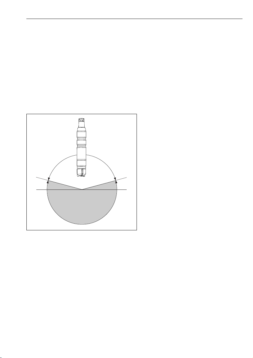
15°
15°
B
A
5 Installation
5.1 Installation conditions
5.1.1 Installation position
Do not install upside-down!
Install the sensor in an assembly, support or appropriate process connection at an angle of
‣
at least 15 ˚ to the horizontal.
Other angles of inclination are not permitted.
‣
Follow the instructions for installing the sensor in the Operating Instructions of the
‣
assembly used.
A Permitted orientation
B Incorrect orientation
A0034236
5.1.2 Immersion depth
50 mm (1.97 in)
Endress+Hauser 15
Page 16
Installation CCS50D
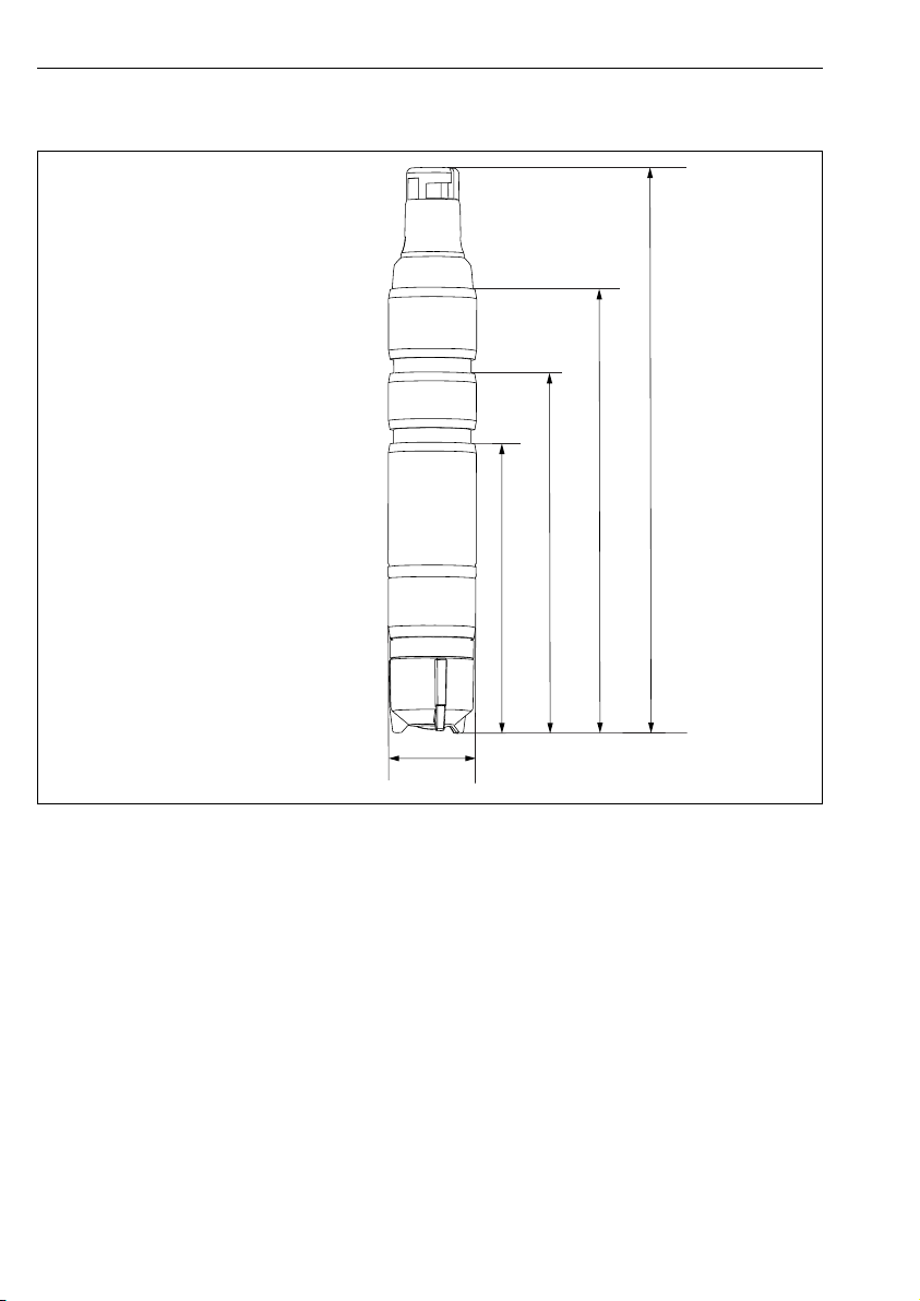
161 (6.34)
82 (3.23)
102 (4.02)
126 (4.96)
!25
(0.98)
5.1.3 Dimensions
A0034238
3 Dimensions in mm (in)
16 Endress+Hauser
Page 17

CCS50D Installation
5.2 Mounting the sensor
5.2.1 Measuring system
A complete measuring system comprises:
• Disinfection sensor CCS50D (membrane-covered, ⌀25 mm) with corresponding
installation adapter
• Flowfit CCA151 flow assembly
• Measuring cable CYK10, CYK20
• Transmitter , e.g. Liquiline CM44x or CM44xR
• Optional: extension cable CYK11
• Optional: proximity switch
• Optional: CPS31
• Optional: Flowfit CCA250 flow assembly (a pH/ORP sensor can additionally be installed
here)
• Optional: immersion assembly Flexdip CYA112
Endress+Hauser 17
Page 18

Installation CCS50D
1
3
6
8
2
7
4
5
4 Example of a measuring system
1 Liquiline CM44x transmitter
2 Power cable for transmitter
3 Disinfection sensor CCS50D (membrane-covered, ⌀25 mm)
4 Outlet from Flowfit CCA151 flow assembly
5 Inlet to Flowfit CCA151 flow assembly
6 Flowfit CCA151 flow assembly
7 Union nut for installing a disinfection sensor in the Flowfit CCA151 flow assembly
8 Measuring cable CYK10
18 Endress+Hauser
A0034241
Page 19

CCS50D Installation
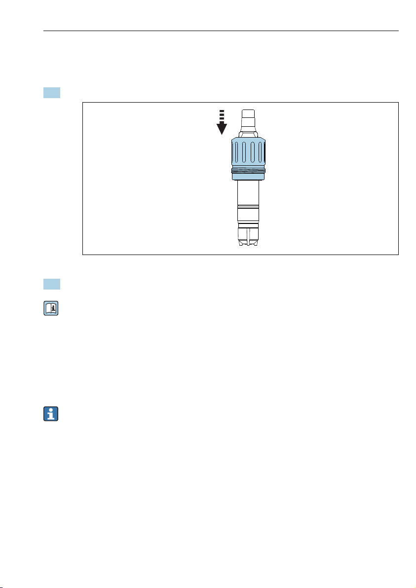
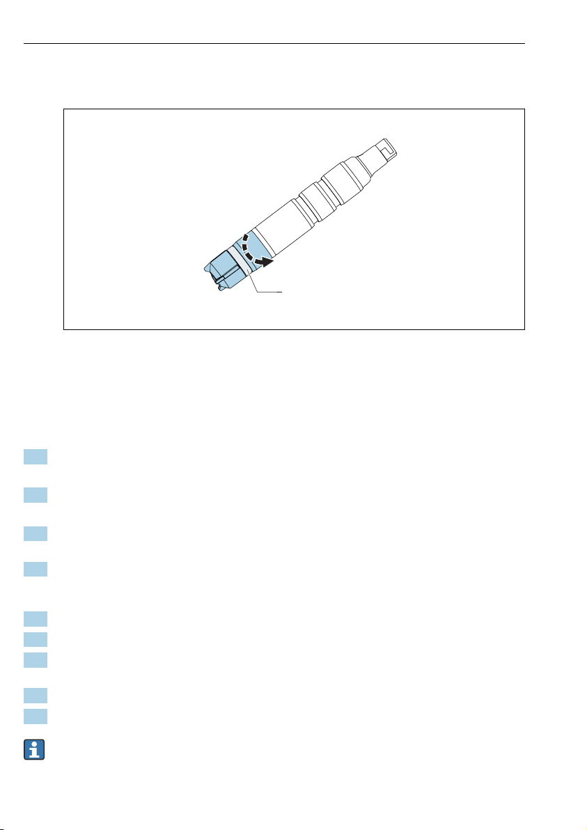
5.2.2 Preparing the sensor
Removing protection cap from sensor
NOTICE
Negative pressure causes damage to the sensor's membrane cap.
If the protection cap is attached, carefully remove it from sensor.
‣
1. When supplied to the customer and when in storage, the sensor is fitted with a
protection cap: First release just the top part of the protection cap by turning it.
A0034263
5 Releasing top part of protection cap by turning
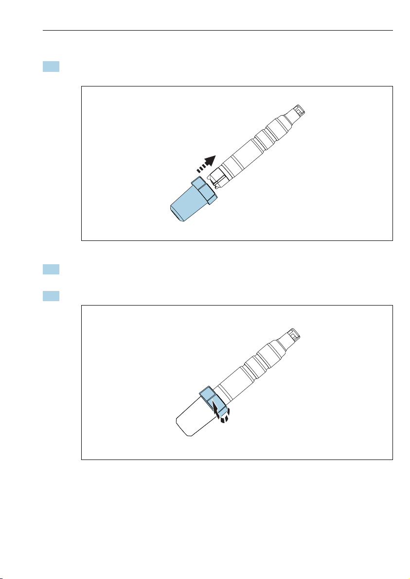
2. Carefully remove protection cap from sensor.
A0034350
6 Carefully remove protection cap
Endress+Hauser 19
Page 20

Installation CCS50D
1
5.2.3 Installing sensor in CCA151 assembly
The disinfection sensor (membrane-covered, ⌀25 mm) is designed for installation in the
Flowfit CCA151 flow assembly.
Please note the following during installation:
The flow rate must be at least 5 l/h (1.3 gal/h).
‣
If the medium is returned to an overflow basin, pipe or similar, the resulting
‣
counterpressure on the sensor must not exceed 1 bar (14.5 psi) and must remain constant.
Avoid negative pressure at the sensor, e.g. due to medium being returned to the suction
‣
side of a pump.
To avoid buildup, heavily contaminated water should also be filtered.
‣
Preparing assembly
1. The assembly is supplied to the customer with a union nut screwed onto the assembly:
unscrew union nut from assembly.
A0034262
7 Flowfit CCA151 flow assembly
1 Union nut
2. The assembly is supplied to the customer with a dummy plug inserted in the assembly:
remove dummy plug from assembly.
20 Endress+Hauser
Page 21

CCS50D Installation
1
2
3
Equip sensor with adapter
The required adapter (clamping ring, thrust collar and O-ring) can be ordered as a mounted
sensor accessory or as a separate accessory → 41.
1. First slide the clamping ring, then the thrust collar, and then the O-ring from the
membrane cap towards the sensor head and into the lower groove.
A0034247
8 Slide clamping ring (1), thrust collar (2) and O-ring (3) upwards from the membrane
cap to the sensor shaft and into the lower groove.
Installing sensor in assembly
2. Slide sensor with adapter for Flowfit CCA151 into the opening in the assembly.
Endress+Hauser 21
Page 22

Installation CCS50D
1
2
3
3. Screw union nut onto assembly on block.
A0034261
9 Flowfit CCA151 flow assembly
1 Disinfection sensor
2 Flowfit CCA151 flow assembly
3 Union nut for securing a disinfection sensor
5.2.4 Installing sensor in CCA250 assembly
The sensor can be installed in the Flowfit CCA250 flow assembly. This allows a pH and an
ORP sensor to also be installed, in addition to the chlorine or chlorine dioxide sensor. A needle
valve controls the flow in the range of 30 to 120 l/h (7.9 to 31.7 gal/h).
Please note the following during installation:
The flow rate must be at least 30 to 120 l/h (7.9 to 31.7 gal/h). If the flow drops below
‣
this value or stops completely, this can be detected by an inductive proximity switch and
used to trigger an alarm with locking of the dosage pumps.
If the medium is returned to an overflow basin, pipe or similar, the resulting
‣
counterpressure on the sensor must not exceed 1 bar (14.5 psi) and must remain constant.
Negative pressure at the sensor, e.g. due to medium being returned to the suction side of a
‣
pump, must be avoided.
22 Endress+Hauser
Page 23
CCS50D Installation
Equip sensor with adapter
The required adapter can be ordered as a mounted sensor accessory or as a separate
accessory.→ 41
1. Slide adapter for Flowfit CCA250 from the sensor head up to the stop on the sensor.
A0034245
10 Slide on adapter for Flowfit CCA250.
2. Lock the adapter in place using the two studs provided.
For detailed information on "Installing sensor in Flowfit CCA250 assembly", see
Operating Instructions for assembly
5.2.5 Installing sensor in other flow assemblies
When using other flow assemblies, please ensure the following:
A flow velocity of at least 15 cm/s (0.49 ft/s) must always be ensured at the membrane.
‣
The flow direction is upwards. Transported air bubbles must be removed so that they do
‣
not collect in front of the membrane.
The flow must be directed to the membrane.
‣
Pay attention to the additional installation instructions in the Operating Instructions for
the assembly.
5.2.6 Installing sensor in immersion assembly CYA112
Alternatively, the sensor can be installed in an immersion assembly with G1 threaded
connection, e. g.
Endress+Hauser 23
Page 24

Installation CCS50D
Equip sensor with adapter
The required adapter can be ordered as a mounted sensor accessory or as a separate
accessory.→ 41
1. Slide adapter for Flexdip CYA112 from the sensor head up to the stop on the sensor.
A0034246
11 Slide on adapter for Flexdip CYA112.
2. Lock the adapter in place using the two studs provided.
For detailed information on "Installing sensor in Flexdip CYA112 assembly", see
Operating Instructions for assembly
5.3 Post-installation check
1. Is the adapter locked in place and unable to move freely?
2. Is the sensor installed in an assembly and not freely suspended from the cable?
Install the sensor in an assembly or directly via the process connection.
3. Is the membrane cap sealed?
Replace if necessary.
4. Is the membrane intact and lying flat: Is the membrane bulging slightly (not flat)?
5. Is there electrolyte in the membrane cap?
If necessary, refill the membrane cap with electrolyte.
24 Endress+Hauser
Page 25
CCS50D Electrical connection
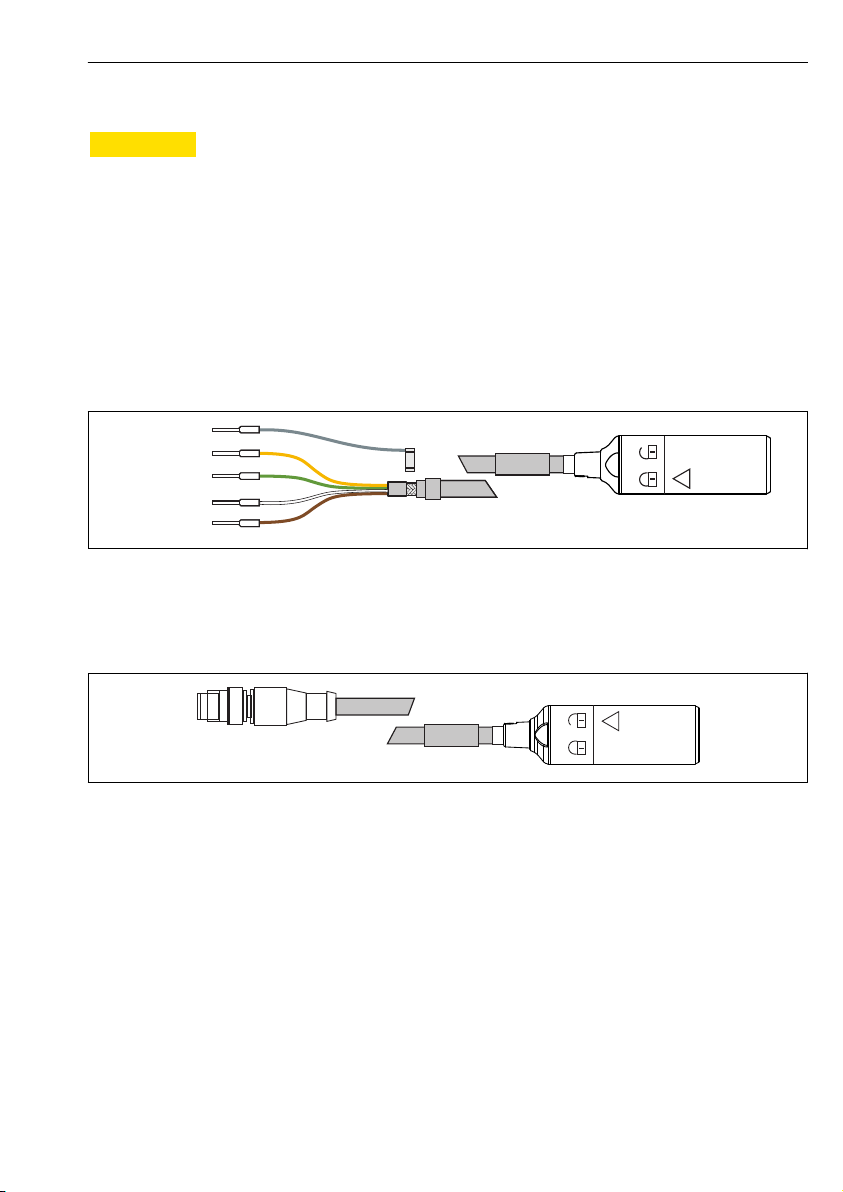
GN/YE
YE
GN
BN
WH
GND
+
–
Com A
Com B
GY
6 Electrical connection
CAUTION
L
Device is live
Incorrect connection may result in injury!
The electrical connection may be performed only by an electrical technician.
‣
The electrical technician must have read and understood these Operating Instructions and
‣
must follow the instructions contained therein.
Prior to commencing connection work, ensure that no voltage is present on any cable.
‣
6.1 Connecting the sensor
The electrical connection to the transmitter is established using measuring cable CYK10 or
CYK20.
A0024019
12 Measuring cable CYK10/CYK20
To extend the cable, use measuring cable CYK11. The maximum cable length is 100 m
‣
(328 ft).
13 Electrical connection, M12 plug
6.2 Ensuring the degree of protection
Only the mechanical and electrical connections which are described in these instructions and
which are necessary for the required, designated use, may be carried out on the device
delivered.
Exercise care when carrying out the work.
‣
Otherwise, the individual types of protection (Ingress Protection (IP), electrical safety, EMC
interference immunity) agreed for this product can no longer be guaranteed due, for example
to covers being left off or cable (ends) that are loose or insufficiently secured.
Endress+Hauser 25
A0018861
Page 26

Electrical connection CCS50D
6.3 Post-connection check
Device condition and specifications Notes
Are the sensor, assembly, or cables free from damage on the outside? Visual inspection
Electrical connection Notes
Are the mounted cables strain-relieved and not twisted?
Is a sufficient length of the cable cores stripped, and are the cores
positioned in the terminal correctly?
Are all the screw terminals properly tightened? Tighten
Are all the cable entries installed, tightened and sealed? For lateral cable entries, make sure the cables
Are all cable entries installed downwards or mounted laterally?
Check the fit (by pulling gently)
loop downwards to allow water to drip off
26 Endress+Hauser
Page 27

CCS50D Commissioning
7 Commissioning
7.1 Function check
Prior to initial commissioning, ensure that:
• The sensor is correctly installed.
• The electrical connection is correct.
• There is sufficient electrolyte in the membrane cap and the transmitter is not displaying a
warning about electrolyte depletion.
Please note the information on the safety data sheet to ensure safe use of the electrolyte.
Always keep the sensor moist after commissioning.
WARNING
L
Escaping process medium
Risk of injury from high pressure, high temperatures or chemical hazards
Before applying pressure to an assembly with cleaning system, ensure that the system has
‣
been connected correctly.
Do not install the assembly in the process if you cannot reliably establish the correct
‣
connection.
7.2 Sensor polarization
The voltage applied by the transmitter between the cathode and anode polarizes the surface
of the cathode. Therefore, after switching on the transmitter with the sensor connected, you
must wait until the polarization period has elapsed before starting calibration.
To achieve a stable display value, the sensor requires the following polarization periods:
Initial commissioning 60 min.
Recommissioning 30 min.
7.3 Sensor calibration
Reference measurement according to the DPD method
To calibrate the measuring system, carry out a colorimetric comparison measurement in
accordance with the DPD method for chlorine dioxide. Chlorine dioxide reacts with diethyl-pphenylendiamine (DPD) to form a red dye, the intensity of the red color being proportional to
the chlorine dioxide content.
Measure the intensity of the red color using a photometer, e.g. PF-3 (→ 41). The
photometer indicates the chlorine dioxide content.
If the photometer used indicates the presence of chlorine, follow the manufacturer's
instructions to convert the chlorine content into the chlorine dioxide content.
Endress+Hauser 27
Page 28

Commissioning CCS50D
Requirements
The sensor reading is stable (no drifts or unsteady values for at least 5 minutes), and the
medium is stable. This is normally guaranteed once the following preconditions have been
met:
• The polarization period has elapsed.
• The flow is constant and within the correct range.
• The sensor and the medium are at the same temperature.
• The pH value is within the permitted range.
• Optional:
For zero point adjustment: electrolyte has been replaced (→ 34)
Zero point adjustment
A zero point adjustment is not required due to the zero point stability of the membranecovered sensor.
However, a zero point adjustment can be performed if desired.
1. To perform a zero point adjustment, operate the sensor for at least 15 minutes in
chlorine-free water, using the assembly or protection cap as a vessel.
2. Alternatively, perform the zero point adjustment using the zero point gel
COY8→ 40.
Slope calibration
Always perform a slope calibration in the following cases:
• After replacing the membrane cap
• After replacing electrolyte
• After the membrane cap has been screwed back on
1. Ensure that the temperature of the medium is constant.
2. Take a representative sample for the DPD measurement. This must be done in close
proximity to the sensor. Use the sampling tap if available.
3. Determine the chlorine dioxide content using the DPD method.
4. Enter the measured value into the transmitter (see Operating Instructions for
transmitter).
5. To ensure greater accuracy, check the calibration several hours or 24 hours later using
the DPD method.
28 Endress+Hauser
Page 29

CCS50D Diagnostics and troubleshooting
8 Diagnostics and troubleshooting
When troubleshooting, the entire measuring point must be taken into account. This
comprises:
• Transmitter
• Electrical connections and lines
• Assembly
• Sensor
The possible causes of error in the following table refer primarily to the sensor. Before
commencing troubleshooting, ensure that the following operating conditions have been met:
• Measurement in "temperature-compensated" mode (can be configured on transmitter
CM44x) or constant temperature following calibration
• Medium flow of at least 5 l/h (1.3 gal/h) (when using Flowfit CCA151 flow assembly)
• No use of organic chlorination agents
If the value measured by the sensor differs significantly from that of the DPD method,
first consider all possible malfunctions of the photometric DPD method (see Operating
Instructions for photometer). If necessary, repeat the DPD measurement several times.
Error Possible cause Remedy
No display, no sensor current No supply voltage at the transmitter
Connection cable between sensor and
transmitter interrupted
There is no electrolyte in the
membrane cap
No input flow of medium
Display value too high Polarization of the sensor not yet
completed
Membrane defective
Shunt resistance (e.g. moisture
contact) in the sensor shaft
Foreign oxidants interfering with
sensor
Establish mains connection
‣
Establish cable connection
‣
Fill membrane cap
‣
Establish flow, clean filter
‣
Wait for polarization to be completed
‣
Replace membrane cap
‣
Remove membrane cap, rub cathode until
‣
dry.
If the transmitter display does not return
‣
to zero, there is a shunt present: replace
sensor.
Examine medium, check chemicals
‣
Endress+Hauser 29
Page 30

Diagnostics and troubleshooting CCS50D
Error Possible cause Remedy
Display value too low Membrane cap not screwed on fully
Membrane soiled
Air bubble in front of membrane
Air bubble between cathode and
membrane
Input flow of medium too low
Foreign oxidants interfering with
DPD reference measurement
Use of organic disinfectants
Display fluctuates
considerably
Hole in membrane
Fill membrane cap with fresh electrolyte
‣
→ 34
Screw membrane cap on fully
‣
Clean membrane → 32
‣
Release air bubble
‣
Remove membrane cap, top up electrolyte
‣
Remove air bubble by tapping on the
‣
outside of the membrane cap
Screw on membrane cap
‣
Establish correct flow
‣
Examine medium, check chemicals
‣
Use suitable agent (e.g. as per DIN 19643)
‣
(water may need to be replaced first)
Use suitable reference system
‣
Replace membrane cap
‣
30 Endress+Hauser
Page 31

CCS50D Maintenance
9 Maintenance
Please note the information on the safety data sheet to ensure safe use of the electrolyte.
Take all the necessary precautions in time to ensure the operational safety and reliability of
the entire measuring system.
NOTICE
Effects on process and process control!
When carrying out any work on the system, bear in mind any potential impact this could
‣
have on the process control system and the process itself.
For your own safety, only use genuine accessories. With genuine parts, the function,
‣
accuracy and reliability are also ensured after maintenance work.
9.1 Maintenance schedule
Interval Maintenance work
If deposits are visible on the membrane (biofilm, limescale) Clean sensor membrane
If dirt is visible on the surface of the electrode body Clean electrode body of
• Slope depending on application:
– At least every 12 months under constant conditions in the permitted range of
0 to 55 °C (32 to 131 °F)
– In the case of severe temperature fluctuations, e.g. from 10 °C (50 °F) to 25°C (77 °F)
and back 100 times
• Zero point calibration:
– If operated in concentration range below 0.5 mg/l (ppm)
– If negative measured value is displayed with factory calibration.
• If electrolyte counter warning is active
• If cap is replaced
• For determining the zero point
• If the slope is too low or too high relative to the nominal slope and the membrane cap is
not visibly damaged or dirty
• If there are grease/oil deposits (dark or transparent spots on the membrane)
• If slope is too high or too low or sensor current is very noisy
• If it is obvious that the sensor current is significantly dependent on the temperature
(temperature compensation not working).
If changes are visible on the cathode or anode (brown coating no longer present) Regenerate sensor
→ 33
sensor → 33
Sensor calibration
Fill membrane cap with
fresh electrolyte
→ 34
Replace membrane cap
→ 34
→ 37
Endress+Hauser 31
Page 32

Maintenance CCS50D
1
2
3
9.2 Maintenance tasks
9.2.1 Cleaning the sensor
Removing sensor from assembly
Remove sensor from assembly CCA151
1. Unscrew union nut from assembly.
1 Disinfection sensor CCS50D
2 Flowfit CCA151 flow assembly
3 Union nut for securing a disinfection sensor CCS50D
2. Pull sensor out through opening in assembly.
Remove sensor from assembly CCA250
1. Remove adapter studs used to secure the adapter to the sensor.
2. Carefully remove adapter in the direction of the sensor head.
3. For detailed information on "Removing sensor from assembly CCA250", see Operating
Instructions for assembly.
Remove sensor from assembly CYA112
1. Remove adapter studs used to secure the adapter to the sensor.
2. Carefully remove adapter in the direction of the sensor head.
3. For detailed information on "Removing sensor from assembly CYA112", see Operating
Instructions for assembly.
32 Endress+Hauser
A0034261
Page 33

CCS50D Maintenance
Cleaning sensor membrane
CAUTION
L
Diluted hydrochloric acid
Hydrochloric acid causes irritation if it comes into contact with the skin or eyes.
When using diluted hydrochloric acid, wear protective clothing such as gloves and goggles.
‣
Avoid splashes.
‣
NOTICE
Chemicals that reduce surface tension (e.g. surfactants in cleaning agents or organic
solvents such as alcohol that can be mixed with water)
Due to chemicals that reduce surface tension, the sensor membrane loses its water-repellent
characteristics and becomes permeable to water. The sensor membrane loses its protective
effect, resulting in measured errors.
Do not use any chemicals that reduce surface tension.
‣
If the membrane is visibly dirty, e.g. biofilm, proceed as follows:
1. Remove sensor from flow assembly → 32.
2. Remove membrane cap → 34.
3. Clean the membrane cap mechanically only using a gentle water jet. Alternatively, clean
for several minutes in diluted acids or in specified cleaning agents without any further
chemical additives.
4. Then rinse thoroughly with water.
5. Screw membrane cap back onto sensor → 34.
Cleaning electrode body
CAUTION
L
Diluted hydrochloric acid
Hydrochloric acid causes irritation if it comes into contact with the skin or eyes.
When using diluted hydrochloric acid, wear protective clothing such as gloves and goggles.
‣
Avoid splashes.
‣
NOTICE
Chemicals that reduce surface tension (e.g. surfactants in cleaning agents or organic
solvents such as alcohol that can be mixed with water)
Due to chemicals that reduce surface tension, the sensor membrane loses its water-repellent
characteristics and becomes permeable to water. The sensor membrane loses its protective
effect, resulting in measured errors.
Do not use any chemicals that reduce surface tension.
‣
1. Remove sensor from flow assembly → 32.
2. Remove membrane cap → 34.
3. Wipe gold electrode carefully using a soft sponge.
4. Rinse electrode body with demineralized water, alcohol or acid.
Endress+Hauser 33
Page 34

Maintenance CCS50D
5. Screw membrane cap back onto sensor → 34.
9.2.2 Filling membrane cap with fresh electrolyte
Please note the information on the safety data sheet to ensure safe use of the electrolyte.
NOTICE
Damage to membrane and electrodes, air bubbles
Possibility of measured errors to complete failure of the measuring point
Avoid damage to membrane and electrodes.
‣
The electrolyte is chemically neutral and is not hazardous to health. Nonetheless, do not
‣
swallow it and avoid contact with eyes.
Keep the electrolyte bottle closed after use. Do not transfer electrolyte to other vessels.
‣
Do not store electrolyte for longer than 2 years. The electrolyte must not be yellow in color.
‣
Observe the use-by date on the label.
Avoid air bubbles when pouring electrolyte into membrane cap.
‣
Fill membrane cap with electrolyte
1. Remove membrane cap → 35.
2. Pour approx. 7 ml (0.24 fl.oz) Fill the membrane cap with electrolyte until it is level
with the start of the internal thread.
3. Slowly screw on membrane cap up to the stop . This will cause excess electrolyte to be
displaced at the valve and thread.
4. If necessary, pat the sensor and membrane cap dry using a cloth.
5. Reset operating hours counter for electrolyte on transmitter. For detailed information,
see Operating Instructions for transmitter.
9.2.3 Replacing membrane cap
1. Remove sensor from flow assembly → 32.
2. Remove membrane cap → 35.
3. Pour fresh electrolyte into the new membrane cap until it is level with the start of the
internal thread.
4. Check if the sealing ring is mounted in the membrane cap.
5. Screw new membrane cap onto sensor shaft → 36.
6. Screw on membrane cap until the membrane at the working electrode is slightly
overstretched (1 mm (0.04 in)).
7. Reset operating hours counter for membrane cap on transmitter. For detailed
information, see Operating Instructions for transmitter.
34 Endress+Hauser
Page 35

CCS50D Maintenance
1
Remove membrane cap
Carefully rotate membrane cap and remove.
‣
A0034406
14 Carefully rotate membrane cap.
A0034408
15 Carefully remove membrane cap.
1 Electrode body
Endress+Hauser 35
Page 36
Maintenance CCS50D
1
Screw membrane cap onto sensor
Screw membrane cap onto sensor shaft: hold sensor by the shaft. Keep valve clear.
‣
A0034480
16 Screw on membrane cap: keep pressure relief valve clear.
1 Pressure relief valve
9.2.4 Storing the sensor
If measurement is suspended for a short period of time and it can be guaranteed that the
sensor will be kept moist while in storage:
1. If the assembly is guaranteed not to empty out,
you may leave the sensor in the flow assembly.
2. If there is a possibility that the assembly may empty out,
remove sensor from assembly .
3. To keep the membrane moist after the sensor has been removed, refill the protection
cap with electrolyte or clean water.
4. Fit protection cap on sensor → 37.
During longterm interruptions to measurement, particularly if dehydration is possible:
1. Remove sensor from assembly.
2. Clean sensor shaft and membrane cap with cold water and leave to dry.
3. Loosely screw on membrane cap up to the stop. This ensures that the membrane
remains slack.
4. Pour electrolyte or clean water into protection cap and attach → 36.
5. For recommissioning, follow the same procedure as for commissioning → 27.
Ensure that no biofouling occurs during longer interruptions to measurement. Remove
continuous organic deposits such as films of bacteria.
36 Endress+Hauser
Page 37
CCS50D Maintenance
Fitting the protection cap on the sensor
1. To keep the membrane moist after the sensor has been removed, fill the protection cap
with some electrolyte or clean water.
A0034264
17 Carefully slide protection cap onto the membrane cap.
2. Top part of protection cap is in the open position.
Carefully slide protection cap onto the membrane cap.
3. Secure protection cap by rotating the top part of the protection cap.
A0034494
18 Securing protection cap by rotating the top part
9.2.5 Regenerating the sensor
During measurement, the electrolyte in the sensor is gradually exhausted due to chemical
reactions. The gray-brown silver chloride layer that is applied to the anode at the factory
continues to grow during sensor operation. However, this has no effect on the reaction taking
place at the cathode.
Endress+Hauser 37
Page 38

Maintenance CCS50D
A change in the color of the silver chloride layer indicates an effect of the reaction that is
taking place. Carry out a visual inspection to ensure that the gray-brown color of the anode
has not changed. If the color of the anode has changed, e.g. if it is spotted, white or silvery,
the sensor must be regenerated.
Send the sensor to the manufacturer for regeneration.
‣
38 Endress+Hauser
Page 39

CCS50D Repair
10 Repair
10.1 Spare parts
For more detailed information on spare parts kits, please refer to the "Spare Part Finding Tool"
on the Internet:
www.endress.com/spareparts_consumables
10.2 Return
The product must be returned if repairs or a factory calibration are required, or if the wrong
product was ordered or delivered. As an ISO-certified company and also due to legal
regulations, Endress+Hauser is obliged to follow certain procedures when handling any
returned products that have been in contact with medium.
To ensure the swift, safe and professional return of the device:
Refer to the website www.endress.com/support/return-material for information on the
‣
procedure and conditions for returning devices.
10.3 Disposal
The device contains electronic components. The product must be disposed of as electronic
waste.
Observe the local regulations.
‣
Endress+Hauser 39
Page 40

Accessories CCS50D
11 Accessories
The following are the most important accessories available at the time this documentation
was issued.
For accessories not listed here, please contact your Service or Sales Center.
‣
11.1 Maintenance kit CCV05
Order according to product structure
• 2 x membrane caps and 1 x electrolyte 50 ml (1.69 fl.oz)
• 1 x electrolyte50 ml (1.69 fl.oz)
• 2 x sealing set
11.2 Device-specific accessories
Memosens data cable CYK10
• For digital sensors with Memosens technology
• Product Configurator on the product page: www.endress.com/cyk10
Technical Information TI00118C
Memosens data cable CYK11
• Extension cable for digital sensors with Memosens protocol
• Product Configurator on the product page: www.endress.com/cyk11
Technical Information TI00118C
Memosens laboratory cable CYK20
• For digital sensors with Memosens technology
• Product Configurator on the product page: www.endress.com/cyk20
Flowfit CCA151
• Flow assembly for chlorine dioxide sensors
• Product Configurator on the product page: www.endress.com/cca151
Technical Information TI01357C
Flowfit CCA250
• Flow assembly for chlorine and pH/ORP sensors
• Product Configurator on the product page: www.endress.com/cca250
Technical Information TI00062C
Flexdip CYA112
• Immersion assembly for water and wastewater
• Modular assembly system for sensors in open basins, channels and tanks
• Material: PVC or stainless steel
• Product Configurator on the product page: www.endress.com/cya112
Technical Information TI00432C
40 Endress+Hauser
Page 41

CCS50D Technical data
Photometer PF-3
• Compact hand-held photometer for determining free available chlorine
• Color-coded reagent bottles with clear dosing instructions
• Order No.: 71257946
Kit adapter CCS5xD for CCA151
• Clamping ring
• Thrust collar
• O-ring
• Order No. 71372027
Adapter kit CCS5x(D) for CCA250
• Adapter incl. O-rings
• 2 studs for locking in place
• Order No. 71372025
Adapter kit CCS5x(D) for CYA112
• Adapter incl. O-rings
• 2 studs for locking in place
• Order No. 71372026
COY8
Zero-point gel for oxygen and chlorine sensors
• Oxygen-free and chlorine-free gel for the verification, zero point calibration and adjustment
of oxygen and chlorine measuring points
• Product Configurator on the product page: www.endress.com/coy8
Technical Information TI01244C
12 Technical data
12.1 Input
12.1.1 Measured values
Chlorine dioxide (ClO
Temperature [°C, °F]
12.1.2 Measuring ranges
CCS50D-**11AD
CCS50D-**11BF 0 to 20 mg/l (ppm) ClO
CCS50D-**11CJ 0 to 200 mg/l (ppm) ClO
Endress+Hauser 41
) [mg/l, μg/l, ppm, ppb]
2
0 to 5 mg/l (ppm) ClO
2
2
2
Page 42

Technical data CCS50D
12.1.3 Signal current
CCS50D-**11AD 135 to 250 nA per 1 mg/l (ppm) ClO
CCS50D-**11BF 35 to 65 nA per 1 mg/l (ppm) ClO
CCS50D-**11CJ 4 to 8 nA per 1 mg/l (ppm) ClO
2
2
2
42 Endress+Hauser
Page 43

CCS50D Technical data
12.2 Performance characteristics
12.2.1 Reference operating conditions
Temperature 20 °C (68 °F)
pH value pH 6 to 7
Flow 40 to 60 cm/s
ClO2-free base medium Deionized water
12.2.2 Response time
T90 < 15 s (after completing polarization)
12.2.3 Measured value resolution of sensor
CCS50D-**11AD
CCS50D-**11BF 0.13 µg/l (ppb) ClO
CCS50D-**11CJ 1.1 µg/l (ppb) ClO
12.2.4
Measured error
4)
0.03 µg/l (ppb) ClO
2
2
2
±2 % or ±5 µg/l (ppb) of value measured (depending on which value is higher)
LOD (limit of detection)
LOQ (limit of quantification)
CCS50D-**11AD 0.0007 mg/l (ppm) 0.002 mg/l (ppm)
CCS50D-**11BF 0.0013 mg/l (ppm) 0.004 mg/l (ppm)
CCS50D-**11CJ 0.0083 mg/l (ppm) 0.025 mg/l (ppm)
12.2.5 Repeatability
CCS50D-**11AD
0.002 mg/l (ppm)
CCS50D-**11BF 0.007 mg/l (ppm)
CCS50D-**11CJ 0.025 mg/l (ppm)
12.2.6 Nominal slope
CCS50D-**11AD
CCS50D-**11BF 50 nA per 1 mg/l (ppm) ClO
CCS50D-**11CJ 6 nA per 1 mg/l (ppm) ClO
195 nA per 1 mg/l (ppm) ClO
2
2
2
4) Based on ISO 15839. The measured error includes all the uncertainties of the sensor and transmitter (measuring
chain). It does not contain all the uncertainties caused by the reference material and adjustments that may have
been performed.
Endress+Hauser 43
Page 44

Technical data CCS50D
12.2.7 Long-term drift
< 1 % per month (mean value, determined while operating at varying concentrations and
under reference conditions)
12.2.8 Polarization time
Initial commissioning 60 min
Recommissioning 30 min
12.2.9 Operating time of the electrolyte
at maximum concentration and 55 °C 60 days
at 50 % of measuring range and 20 °C 1 year
at 10 % of measuring range and 20 °C 2 years
12.3 Environment
12.3.1 Ambient temperature range
-20 to 60 °C (-4 to 140 °F)
12.3.2 Storage temperature
Longterm storage Storage up to max 48 h
With electrolyte 0 to 35 °C (32 to 95 °F) (non-freezing) 35 to 50 °C (95 to 122 °F)
Without electrolyte –20 to 60 °C (–4 to 140 °F)
12.3.3 Degree of protection
IP68 (1.8 m (5.91 ft)) water column over 7 days at 20 °C (68 °F)
12.4 Process
12.4.1 Process temperature
0 to 55 °C (32 to 130 °F), non-freezing
12.4.2 Process pressure
The inlet pressure depends on the specific fitting and installation.
The measurement can take place with a free outlet.
The medium pressure directly upstream from the sensor membrane must not exceed
1 bar (14.5 psi) abs.
In terms of sensor condition and performance, it is essential that the flow velocity limits
‣
specified in the following table be observed.
44 Endress+Hauser
Page 45

CCS50D Technical data
Flow
velocity
[cm/s]
Minimum 15 30 5 The sensor is suspended freely in the medium; pay
Maximum 80 145 20
Flowfit
CCA250
Flowfit
CCA151
Volume flow [l/h]
FlexdipCYA112
attention to the minimum flow velocity of 15 cm/s
during installation.
12.4.3 pH range
Stability range of chlorine dioxide (ClO2) pH 2 to 10
1)
Calibration pH 4 to 8
Measurement pH 4 to 9
From pH values > 9, ClO2 is unstable and decomposes.
1)
Up to pH 3.5 and in the presence of chloride ions (Cl-), free chlorine is produced and included in the
measurement
12.4.4 Flow
At least 5 l/h (1.3 gal/h), in the Flowfit CCA151 flow assembly
At least 30 l/h (7.9 gal/h), in the Flowfit CCA250 flow assembly
12.4.5 Minimum flow
At least 15 cm/s (0.5 ft/s) , e.g. with Flexdip CYA112 immersion assembly
12.5 Mechanical construction
12.5.1 Dimensions
→ 16
12.5.2 Weight
Sensor with membrane cap and electrolyte (without protection cap and without adapter) Approx. 95 g (3.35 oz)
12.5.3 Materials
Sensor shaft
PVC
Membrane PVDF
Membrane cap PVDF
Protection cap • Vessel: PC Makrolon (polycarbonate)
• Seal: Kraiburg TPE TM5MED
• Cover: PC Makrolon (polycarbonate)
Sealing ring FKM
12.5.4 Cable specification
max. 100 m (330 ft), incl. Cable extension
Endress+Hauser 45
Page 46

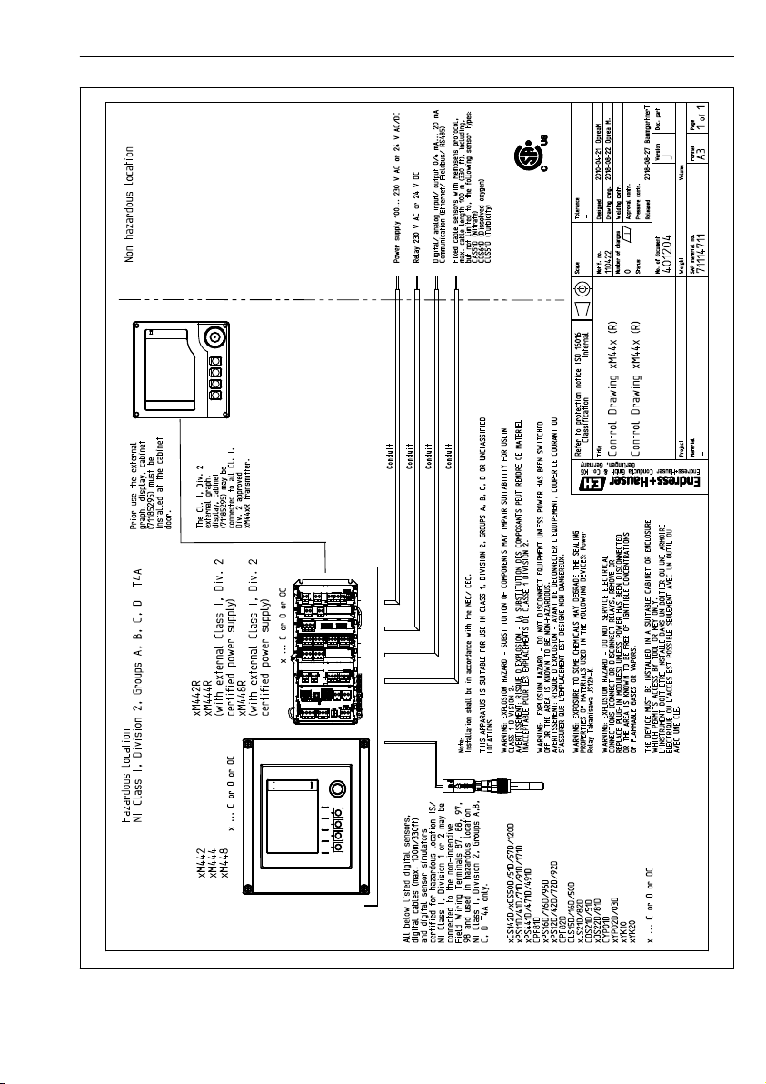
Installation and operation in hazardous environment Class I Div. 2 CCS50D
13 Installation and operation in hazardous environment
Class I Div. 2
Non-sparking device for use in specified hazardous environment in accordance with:
• cCSAus Class I Div. 2
• Gas group A, B, C, D
• Temperature class T6, -5 °C (23 °F) < Ta < 55 °C (131 °F)
• Control drawing: 401204
46 Endress+Hauser
Page 47
CCS50D Installation and operation in hazardous environment Class I Div. 2
Endress+Hauser 47
Page 48

Index CCS50D
Index
A
Accessories ..................... 40
Ambient temperature range ........... 44
C
Cable specification ................. 45
Check
Connection .................. 26
Function ....................27
Installation .................. 24
Cleaning .......................32
Connection
Check ..................... 26
Ensuring the degree of protection ..... 25
D
Declaration of conformity .............14
Degree of protection
Ensuring ....................25
Technical data ................ 44
Designated use ....................6
Device description .................. 8
Diagnostics ..................... 29
Disposal ....................... 39
E
Effect on the measured signal
Flow ....................... 9
pH value .....................9
Temperature ................. 10
Electrical connection ................25
Environment .................... 44
Ex approvals .................... 14
F
Flow ........................9, 45
Flow assembly ................. 22, 23
Function check ................... 27
I
Immersion assembly ................23
Incoming acceptance ............... 13
Installation
Check ..................... 24
Flow assembly ................ 22
Immersion assembly .............23
Installation position ............. 15
Sensor ..................... 17
Installation position ................ 15
L
Long-term drift ...................44
M
Maintenance schedule ...............31
Maintenance tasks .................32
Materials ...................... 45
Maximum measured error ............ 43
Measured signal ................... 9
Measured value resolution ............ 43
Measured values .................. 41
Measuring principle .................8
Measuring ranges ................. 41
Measuring system ................. 17
Minimum flow ................... 45
Mounting instructions ...............15
N
Nameplate ..................... 13
Nominal slope ................... 43
O
Operating principle ................. 8
Operating time of the electrolyte .........44
P
Performance characteristics ........... 43
pH range .......................45
pH value ........................9
Polarization time ..................44
Post-installation check .............. 27
Process ........................44
Process pressure .................. 44
Process temperature ................44
R
Reference operating conditions ......... 43
Regeneration .................... 37
Repair ........................ 39
Repeatability .................... 43
Response time ................... 43
48 Endress+Hauser
Page 49

CCS50D Index
Return ........................ 39
S
Safety instructions ..................6
Scope of delivery .................. 14
Sensor
Calibration .................. 27
Cleaning ....................32
Connecting .................. 25
Mounting ................... 17
Polarization ..................27
Regenerating ................. 37
Storage .................... 36
Spare parts ..................... 39
Storage ....................... 36
Storage temperature ................44
Symbols ........................ 4
T
Technical data
Environment ................. 44
Input ......................41
Mechanical construction .......... 45
Performance characteristics ........ 43
Process .....................44
Temperature .................... 10
Troubleshooting .................. 29
U
Use ...........................6
W
Warnings ....................... 4
Weight ........................45
Endress+Hauser 49
Page 50

Page 51

Page 52

*71431040*
71431040
www.addresses.endress.com
 Loading...