

Page 1

Operating Instructions
CCS120
Sensor for total chlorine
BA388C/07/en/07.06
51517372
Page 2

Brief overview
Here is how to use these Operating Instructions to commission your sensor quickly and safely:
Safety instructions
→ Page 4 ff.
→ Page 5
→ Page 7
→ Page 8 ff.
→ Page 11 ff. Refer to these pages for sensor wiring.
→ Page 14 ff. This chapter describes how to fill in the electrolyte.
General safety instructions
Explanation of the warning symbols
Æ
Installation
Here you can find installation conditions such as sensor dimensions.
Installation examples can be found here.
Æ
Wiring
Æ
Operating
Æ
Commissioning
→ Page 16 ff. Here you find how to calibrate the sensor.
Æ
Maintenance
→ Page 18
→ Page 19 ff.
→ Page 20 ff. If faults occur during operation, use the checklist to locate the cause.
→ Page 25 ff. You can find important terms and keywords on the individual sections
It is absolutely essential to carry out maintenance tasks on a regular basis.
An overview of the available spare parts and accessories.
Æ
Trouble shooting
Æ
Index
here. Use the keyword index to find the information you need quickly and
efficiently.
Page 3

CCS120
Table of contents
1 Safety instructions . . . . . . . . . . 4
1.1 Designated use . . . . . . . . . . . . . . . . . . . . . . 4
1.2 Installation, commissioning and operation . 4
1.3 Operational safety . . . . . . . . . . . . . . . . . . . 5
1.4 Return . . . . . . . . . . . . . . . . . . . . . . . . . . . . 5
1.5 Notes on safety icons and symbols . . . . . . . 5
2 Identification . . . . . . . . . . . . . . 6
2.1 Product structure . . . . . . . . . . . . . . . . . . . . 6
2.2 Scope of delivery . . . . . . . . . . . . . . . . . . . . 6
3 Installation . . . . . . . . . . . . . . . . 6
3.1 Incoming acceptance, transport, storage . . . 6
3.2 Installation conditions . . . . . . . . . . . . . . . . 7
3.3 Installation instructions . . . . . . . . . . . . . . . 8
3.4 Post-installation check . . . . . . . . . . . . . . . 10
4 Wiring . . . . . . . . . . . . . . . . . . 11
4.1 Direct connection to the transmitter . . . . . 11
4.2 Connection via junction box . . . . . . . . . . 12
4.3 Post-connection check . . . . . . . . . . . . . . . 12
9 Troubleshooting . . . . . . . . . . . 20
9.1 Troubleshooting instructions . . . . . . . . . . . 20
9.2 Return . . . . . . . . . . . . . . . . . . . . . . . . . . . 22
9.3 Disposal . . . . . . . . . . . . . . . . . . . . . . . . . . 22
10 Technical data . . . . . . . . . . . . 23
10.1 Input . . . . . . . . . . . . . . . . . . . . . . . . . . . . 23
10.2 Output . . . . . . . . . . . . . . . . . . . . . . . . . . . 23
10.3 Performance characteristics . . . . . . . . . . . . 23
10.4 Power supply . . . . . . . . . . . . . . . . . . . . . . 24
10.5 Environment . . . . . . . . . . . . . . . . . . . . . . 24
10.6 Mechanical construction . . . . . . . . . . . . . . 24
Index. . . . . . . . . . . . . . . . . . . . 25
5 Operation . . . . . . . . . . . . . . . . 13
5.1 Sensor design . . . . . . . . . . . . . . . . . . . . . . 13
5.2 Measuring principle . . . . . . . . . . . . . . . . . 13
5.3 Electrolyte fill in . . . . . . . . . . . . . . . . . . . . 14
6 Commissioning. . . . . . . . . . . . 16
6.1 Function check . . . . . . . . . . . . . . . . . . . . 16
6.2 Polarisation . . . . . . . . . . . . . . . . . . . . . . . 16
6.3 Calibration . . . . . . . . . . . . . . . . . . . . . . . . 16
7 Maintenance. . . . . . . . . . . . . . 18
8 Accessories. . . . . . . . . . . . . . . 19
8.1 Connection accessories . . . . . . . . . . . . . . 19
8.2 Installation accessories . . . . . . . . . . . . . . . 19
8.3 Transmitter . . . . . . . . . . . . . . . . . . . . . . . 19
8.4 Maintenance/calibration . . . . . . . . . . . . . 20
Endress+Hauser
Page 4

Safety instructions CCS120
1 Safety instructions
1.1 Designated use
The sensor is used for continuous measurement of total chlorine in water. Within this context
the following compounds are included in the term total chlorine:
• free chlorine (Cl2 (dissolved), HOCl, OCL-)
• bound chlorine (chloramines)
• organic-bound chlorine (e.g. cyanuric acid derivates)
Typical applications are:
• Controlling total chlorine content of drinking, industrial, process, cooling water and pool
sector
• Measuring total chlorine content in fresh water and sea water for process, swimming pool and
whirl pool treatment
Any other use than the one described here compromises the safety of persons and the entire
measuring system and is, therefore, not permitted.
The manufacturer is not liable for damage caused by improper or non-designated use.
1.2 Installation, commissioning and operation
Please note the following items:
• Installation, commissioning, operation and maintenance of the measuring system must only
be carried out by trained technical personnel.
The technical personnel must be authorized for the specified activities by the system operator.
• Electrical connection must only be carried out by a certified electrician.
• Technical personnel must have read and understood these Operating Instructions and must
adhere to them.
• Before commissioning the entire measuring point, check all the connections for
correctness. Ensure that electrical cables and hose connections are not damaged.
• Do not operate damaged products and secure them against unintentional
commissioning. Mark the damaged product as being defective.
• Measuring point faults may only be rectified by authorized and specially trained
personnel.
• If faults can not be rectified, the products must be taken out of service and secured against
unintentional commissioning.
• Repairs not described in these Operating Instructions may only be carried out at the
manufacturer’s or by the service organisation.
4 Endress+Hauser
Page 5

CCS120 Safety instructions
1.3 Operational safety
The sensor has been designed and tested according to the state of the art and left the factory in
perfect functioning order.
Relevant regulations and European standards have been met.
As the user, you are responsible for complying with the following safety conditions:
• Installation instructions
• Local prevailing standards and regulations.
1.4 Return
If the sensor has to be repaired, please return it cleaned to the sales centre responsible.
Please use the original packaging, if possible.
Please enclose the completed "Declaration of Hazardous Material and De-Contamination" (copy
the second last page of these Operating Instructions) with the packaging and the transportation
documents.
No repair without completed declaration!
#
"
!
1.5 Notes on safety icons and symbols
Warning!
This symbol alerts you to hazards. They can cause serious damage to the instrument or to
persons if ignored.
Caution!
This symbol alerts you to possible faults which could arise from incorrect operation. They could
cause damage to the instrument if ignored.
Note!
This symbol indicates important items of information.
Endress+Hauser 5
Page 6

Identification CCS120
2 Identification
2.1 Product structure
Mesuring range
A 0.1 ... 10 mg/l
Head type
S Thread NPT 3/4"; plug TOP 68
Options
0none
CCS120- complete order code
2.2 Scope of delivery
The following items are included in the delivery:
• 1 sensor CCS120
• 1 bottle containing electrolyte (50 ml) and nozzle
• 1 membrane cap for replacement
• 1 operating instructions BA 388C/07/en
3 Installation
3.1 Incoming acceptance, transport, storage
• Make sure the packaging is undamaged!
Inform the supplier about damage to the packaging. Keep the damaged packaging until the
matter has been settled.
• Make sure the contents are undamaged!
Inform the supplier about damage to the delivery contents. Keep the damaged products until
the matter has been settled.
• Check that the scope of delivery is complete and agrees with your order and the shipping
documents.
• The packaging material used to store or to transport the product must provide shock
protection and humidity protection. The original packaging offers the best protection. Also,
keep to the approved ambient conditions (see "Technical data").
• If you have any questions, please contact your supplier or your sales center responsible.
6 Endress+Hauser
Page 7
CCS120 Installation
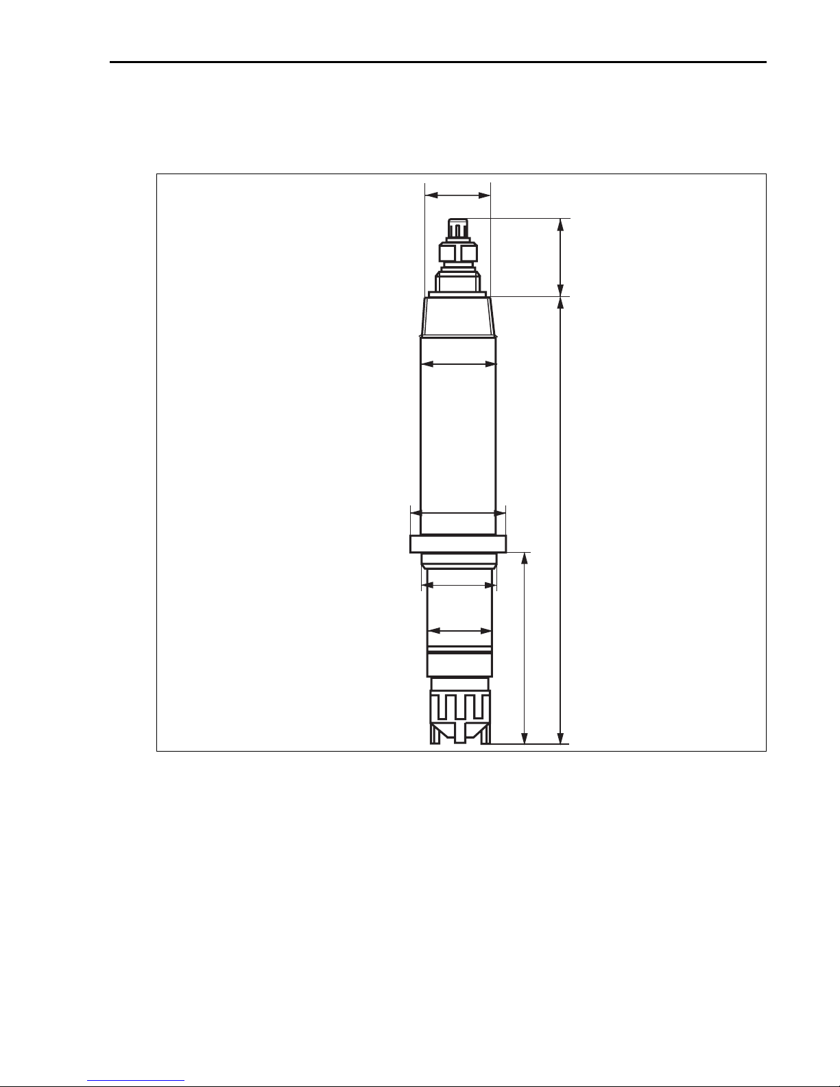
3.2 Installation conditions
3.2.1 Dimensions
NPT 3/4
27/1.06
Ø 29/
1.14
Fig. 1: Dimensions
Ø 36/
1.42
183/7.20
Ø 28.8/
1.13
Ø 25/
0.98
74/2.91
mm/inch
a0003082
Endress+Hauser 7
Page 8
Installation CCS120
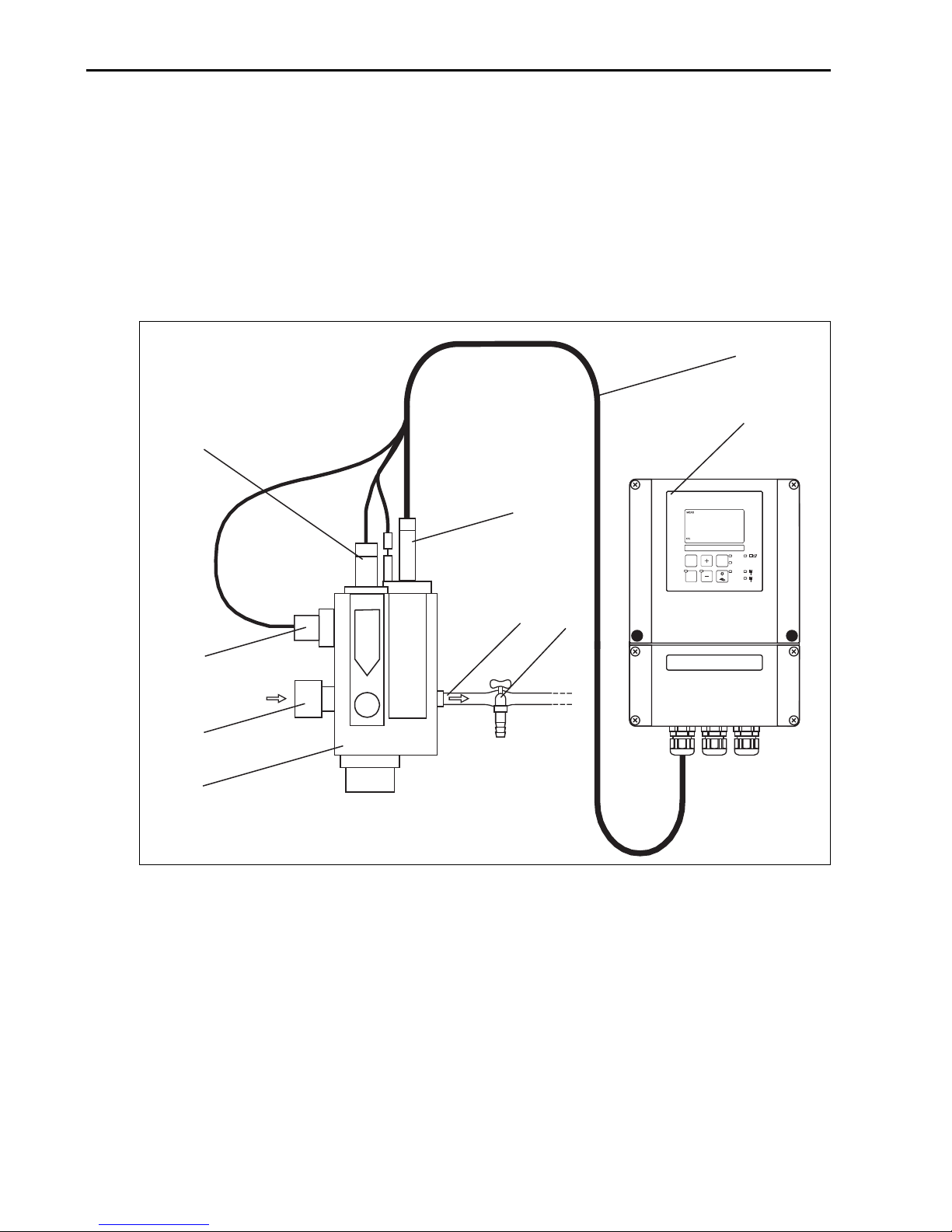
3.3 Installation instructions
3.3.1 Measuring system
A complete measuring system in the flow mode comprises at least:
• Chlorine sensor
• Transmitter Liquisys M CCM223/253
• Special measuring cable
• Flow assembly
8
9
4
5
25.0 ¡C
CAL REL
E
6
7
3
2
1
Fig. 2: Measuring system in the flow mode (example)
1 Flow assembly CCA250 6 Medium outlet
2 Medium inlet 7 Sampling tap
3 Inductive proximity switch for flow monitoring 8 Measuring cable CPK9-N*A1B
4 Mounting place for pH/redox sensor 9 Transmitter
5 Chlorine sensor CCS120
0.42
mg/l
REL1
ALARM
REL2
REL1
REL2
a0001691
The measuring system described above is available as CCE-system (fully mounted on a board).
8 Endress+Hauser
Page 9
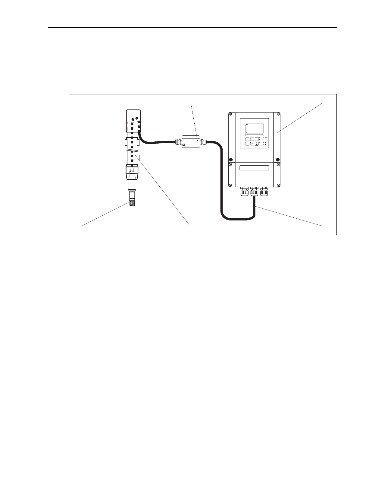
CCS120 Installation
A complete measuring system in the immersion mode comprises at least:
• Chlorine sensor
• Transmitter Liquisys M CCM223/253
• Special measuring cable
• Immersion assembly
1
mg/l
0.42
25.0 ¡C
REL1
ALARM
REL2
CAL REL
REL1
E
REL2
5
4
Fig. 3: Measuring system in the immersion mode (example)
1 Junction box VBM 4 Immersion assembly CYA611-0B
2 Transmitter 5 Chlorine sensor CCS120
3 Measuring cable CYK71
2
3
a0003087
3.3.2 Installing the sensor in flow assembly CCA250
The flow assembly CCA250 is designed for on-site installation of the sensor. In addition to the
chlorine sensor, a pH and redox sensor can be installed. A needle valve regulates the flow within
the range of 30 ... 100 l/h (7.92 ... 26.40 US.gal/h). If the value drops below 30 l/h (7.92
US.gal/h) or flow stops completely, this can be detected by an inductive proximity switch and
an alarm signal plus locking of the dosage pumps can be triggered.
Note the instructions and safety guidelines in the operating instructions of the flow assembly.
If the medium is fed back into a surge tank, pipeline or the like, ensure that the thus generated
back pressure on the sensor does not exceed 1 bar (14.5 psi) and remains constant.
Negative pressure at the sensor, e.g. by feedback of medium to the suction side of a pump, must
be avoided.
Endress+Hauser 9
Page 10

Installation CCS120
3.3.3 Installing the sensor in immersion assembly CYA611
The immersion assembly CYA611-0B is designed for on-site installation of the sensor. Cover the
thread NPT 3/4" with a layer of Teflon tape. Screw the sensor into the assembly.
Note the instructions and safety guidelines in the operating instructions of the immersion
assembly.
3.4 Post-installation check
• Check the membrane for leak tightness und replace it if necessary.
• Is the sensor installed in an assembly and is not suspended from the cable?
10 Endress+Hauser
Page 11

CCS120 Wiring
4 Wiring
Warning!
#
• The electrical connection must only be carried out by a certified electrician.
• Technical personnel must have read and understood the instructions in this manual and must
adhere to them.
• Ensure that there is no voltage at the power cable before beginning the connection work.
4.1 Direct connection to the transmitter
Use the measuring cable CPK9-N*A1B (internal PM wire) to connect the sensor according to
the following connection table. See also the notes in the operating instructions of the transmitter.
Cable with TOP68 coupling Liquisys
Pin Assignment Core Terminal
1 TC-signal coax-inner (white) 90
2 AGND coax-outer (black) 12
3
4 +UB (15 V) green 85
5 NTC1 yellow* 11
NTC1 white* 11
6 NTC2/AGND brown 86
S screen S S
* The white and the yellow cores are connected inside of the TOP68 coupling.
5
4
3
2
Fig. 4: TOP68 plug pin arrangement (view from contact side)
5
6
6
1
1
4
3
2
a0001689
Endress+Hauser 11
Page 12

Wiring CCS120
4.2 Connection via junction box
To lengthen the sensor connection you require the junction box VBM (Fig. 5, Fig. 6) . The
connection is lengthened to the transmitter using the special measuring cable CYK71.
Pg 13,5
62.5/2.46
113/4.45
54/2.13
136/5.35
125/4.92
Fig. 5: Junction box VBM, side view
C07-COS41xxx- 04-05-00-en-00 3.eps
mm/inch
Fig. 6: Junction box VBM, top view
10/0.09
52/2.05
80/3.15
mm/inch
C07-COS41xxx- 04-05-00-en-00 4.eps
4.3 Post-connection check
Instrument status and specifications Remarks
Are the sensor, assembly, junction box or cable damaged? Visual inspection
Electrical connection Remarks
Does the supply voltage of the transmitter match the specifications on the
nameplate?
Are the installed cables strain-relieved and not twisted?
Is the cable type route completely isolated? Power cable/weak current cable
Are the power supply and signal cable correctly connected to the
transmitter?
110/230 V AC
24 V AC/DC
Use the connection diagram of
CCM2x3.
Are all the screws terminals properly tightened?
Are all the cable entries installed, tightened and sealed? For lateral cable entries : cable loops
Are all the cable entries installed downwards or lateral?
12 Endress+Hauser
downwards for water to be able to drip off.
Page 13

CCS120 Operation
5 Operation
5.1 Sensor design
2
1
4
3
Fig. 7: Sensor design
1 Membrane cap 3 Thread NPT 3/4"
2 Sensor shaft 4 TOP68 plug
a0006354
5.2 Measuring principle
The amperometric sensor is based on the conversion of the measuring variable chlorine in
electrical current. Two electrodes covered by an electrolyte are in contact to the medium via a
membrane. It has a platinum working electrode and a silver halogenide coated counter or
reference electrode. The chlorine compounds contained in the medium diffuse through the
membrane. The constant polarisation voltage between the two electrodes instigates the
electrochemical reaction of the chlorine compounds on the working electrode. The resulting
current is measured as a primary signal (amperometric measurement principle). It is proportional
to the chlorine concentration within the sensor’s operating range and only slightly pH dependant
for this type of sensor. The primary signal is converted by the amplifier electronics of the sensor
into a 0 ... 5 µA output signal which is displayed by the transmitter.
Endress+Hauser 13
Page 14

Operation CCS120
5.3 Electrolyte fill in
Warning!
#
Do not swallow the electrolyte. Avoid contact of the electrolyte with skin and eyes. Otherwise
wash with a lot of water. In case of eye inflamation, contact a doctor.
Caution!
"
• Do not touch or damage the membrane or electrodes.
• The electrolyte is sensitive to oxidation: always keep the electrolyte bottle closed after use. Do
not transfer the electrolyte into other containers.
• The electrolyte should not be stored for more than 1 year and should not yellow (use by date,
see label).
• Avoid forming air bubbles as far as possible when pouring the electrolyte into the membrane
cap.
• The membrane cap must be used once only.
!
Note!
• Store the electrolyte bottle upside down in order that the viscous electrolyte can be poured
easily and bubble free into the membrane cap.
• Smaller bubbles will not interfere, larger bubbles leave the electrolyte by rising to the surface.
3
4
2
1
Fig. 8: Membrane cap with electrolyte bottle
1 Nozzle 4 Membrane cap
2Vent hole 5Rubber seal
3 Electrolyte bottle A Electrolyte filling level
5
A
a0001688
14 Endress+Hauser
Page 15

CCS120 Operation
Perform the following steps to fill the membrane cap with electrolyte:
1. Open the electrolyte bottle and screw on the nozzle.
2. Squeeze out excess air.
3. Place the electrolyte bottle completely onto the membrane cap (Fig. 8).
4. Slowly squeeze the electrolyte out of the bottle in one steady stream, while continously
retracting the bottle. The cap is completely full when the electrolyte reaches the lower
edge of the thread.
Now you have to install the membrane cap:
1. Place the sensor shaft vertically onto the filled membrane cap.
2. Do not cover the vent hole below the rubber seal with your fingers.
3. Tighten on the membrane cap by hand as far as possible. There should not be a visible gap
between the sensor shaft and membrane cap. When you screw on the cap, excess
electrolyte will leak out through the hole below the rubber seal.
4. Wipe away any electrolyte with a soft paper tissue or similar.
5. Rinse the nozzle thoroughly with a clean, warm water jet so that no electrolyte remains
on the inside and outside of the nozzle.
Endress+Hauser 15
Page 16

Commissioning CCS120
6 Commissioning
!
Note!
• Read also the instructions for operation and commissioning in the operating instructions of the
transmitter.
• The power supply to the transmitter and to the sensor must not be interrupted. If the power
supply is interrupted (> 2 hours) the sensor must be re-commissioned (polarisation time).
• Do not switch off the measuring device during intermittent operation. Dosing devices may be
controlled by timer switches.
However, if no disinfectant is metered over a longer period of time (weeks), the sensor must
be disconnected from the system and stored dry.
• Once the sensor has been commissioned it must be kept permanently wet.
6.1 Function check
Before first commissioning, check if:
• the sensor ist correctly installed
• the electrical connection is correct.
6.2 Polarisation
The voltage applied between cathode and anode by the transmitter polarises the surface of the
working electrode. Therefore, after switching on the transmitter with connected sensor, you
have to wait until the polarisation period has elapsed before you can start a calibration.
In order to achieve a stable display value the sensor needs the following polarisation period:
First commissioning: 24 h
After changing membrane: 1 - 6 h
Re-commissioning: approx. 4 - 24 h
6.3 Calibration
Reference measurement according to the DPD method
The calibration of the measuring system requires a colormetric reference measurement
according to the DPD method. Chlorine reacts with diethyl-p-phenylenadiamine (DPD) by
producing a red dye, the intensity of the red colour being proportional to the chlorine
concentration.
The intensity of the red dye is measured by a photometer (e.g. CCM182, see accessories) and
displayed as chlorine concentration.
16 Endress+Hauser
Page 17

CCS120 Commissioning
Requirements
The sensor reading is stable (no drifts or unsteady values for at least 5 minutes). This is normally
fulfilled, when:
• The polarisation period is finished.
• The flow is constant and within the correct range.
• The sample medium and the sensor are at the same temperature.
• The pH value is within the admissible range.
Zero point calibration
Zero point calibration is only necessary when the sensor is used at the lower limit of the
measuring range.
For zero point calibration, perform the following steps:
1. Remove the sensor from the assembly (see operating instructions of the assembly).
2. Clean the sensor thoroughly. The sensor must be totally free of chlorine for the next
working step.
3. Stir the sensor in a container filled with clean water (free of chlorine and bromine) until
the measured value remains stable.
4. Adjust the transmitter to zero according to it operating instructions.
5. Reinstall the sensor into the assembly (see operating instructions of the assembly).
Slope calibration
For slope calibration, perform the following steps:
1. Insert the sensor into the assembly, if not already done (see operating instructions of the
assembly).
2. Take a sample for DPD measurement. Sampling location has to be close to the installed
sensor. Use the sampling tap in the case of the compact chlorine system CCE1.
3. Determine the total chlorine content with a photometer (e.g. CCM182, see accessories)
according to the DPD 1 / DPD 3 method. See the operating instructions of the
photometer. Alternatively you can use the DPD 4 methode.
4. Enter the measured value into the transmitter (see operating instructions of the
transmitter).
5. After initial installation of the sensor, check the calibration by DPD measurement 24 hours
later.
The following calibration intervals are recommended:
• Drinking, industrial, process and cooling water: depending on the specific conditions
(1 - 4 weeks)
• Swimming pools: weekly
• Whirlpools: daily
!
Note!
Carry out a slope calibration every time the membrane or electrolyte is changed.
Endress+Hauser 17
Page 18

Maintenance CCS120
7 Maintenance
!
Note!
• Service the sensor regularly to avoid incorrect dosing within a control system, due to incorrect
measured value.
• Do not touch the electrodes or allow them to come into contact with greasy substances.
• Never attempt to clean the membrane with acid/alkaline solutions, cleaning reagents or
mechanical aids (brushes or similar).
Maintenance intervals based on experience are:
• Drinking, industrial, process and cooling water: depending on the specific conditions
(1-4 weeks)
• Swimming pools: weekly
• Whirlpools: daily
Perform the following maintenance work:
• Check the sensor for dirt, algae and air bubbles. If neccessary clean the sensor with clear water
and a soft tissue. Eliminate air bubbles by increasing the flow rate.
• Check the displayed sensor value on the transmitter according to the DPD 1 / DPD 3 method.
Use a photometer (e.g. CCM182 , see accessories).
• If necessary, recalibrate the sensor.
• If calibration cannot be carried out properly, replace the membrane cap and repeat the
calibration.
18 Endress+Hauser
Page 19

CCS120 Accessories
8 Accessories
8.1 Connection accessories
Junction box VBM
• For cable extension, with 10 terminals
• IP 65 / NEMA 4X
• Material: aluminum
• Order numbers:
– cable entry Pg 13.5: 50003987
– cable entry NPT ½": 51500177
• Measuring cable CCS120-1M, cable length: 1 m (3.28 ft), for compact chlorine system CCE1
order no. 51517204
• Special measuring cable CPK9-N*A1B internal PM wire
For sensors with TOP68 plug-in head, for high-temperature and high-pressure applications,
IP 68
Ordering acc. to product structure, see Technical Information (TI118C/07/en)
8.2 Installation accessories
• Flow assembly CCA250
for chlorine, chlorine dioxide, pH and redox;
Ordering acc. to product structure, see Technical Information (TI062C/07/en)
• Immersion assembly Dipfit W CYA611-0B
for sensor immersion in basins, open channels and tanks, PVC;
Ordering acc. to product structure (Technical Information TI166C/07/en)
• Compact chlorine system CCE1
Factory-assembled and wired panel for transmitter with flow assembly CCA250-A1; see also
Technical Information TI014C/07/en
8.3 Transmitter
• Liquisys M CCM223/253
Transmitter for chlorine, field or panel-mounted housing,
Hart® or PROFIBUS available,
Ordering acc. to product structure, see Technical Information (TI214C/07/en)
Endress+Hauser 19
Page 20

Troubleshooting CCS120
8.4 Maintenance/calibration
• Photometer CCM182; microprocessor-controlled photometer for chlorine, pH value,
cyanuric acid;
Chlorine measuring range: 0.05 to 6 mg/l
pH measuring range: 6.5 to 8.4
• Electrolyte for CCS120, 50 ml
order no. 51516343
• Service kit for CCS120, consists of 2 membrane caps and 1 bottle of electrolyte (50 ml)
order no. 51517284
9 Troubleshooting
9.1 Troubleshooting instructions
Troubleshooting must take account of the whole measuring system. The measuring system
consists of:
•Transmitter
• Electrical leads and connectors
•Assembly
•Sensor
The possible causes of failure listed in the following table primarily refer to the total chlorine
sensor. Before commencing troubleshooting, please ensure that the following operating
conditions in "Technical data" are met:
• Chlorine content lies within the corresponding measurement range of the sensor
(0.1 ... 10 mg/l)
• Constant pH in the range 5.5 - 9.5
• Constant temperature in the range 4 ... 45 °C (39 ... 113 °F)
• Conductivity: 0.03 ... 40 mS/cm
• Flow: 30 ... 100 l/h (7.92 ... 26.40 US.gal./h)
If the value measured by the sensor differs significantly from that of the DPD method you need
to first consider all possible malfunctions of the DPD photometric method (see operating
instructions of the photometer). If necessary, repeat the DPD measurement several times.
20 Endress+Hauser
Page 21

CCS120 Troubleshooting
Fault Possible cause Action
Sensor cannot be calibrated.
Measured value higher than
DPD measurement
Sensor cannot be calibrated.
Measured value lower than DPD
measurement
Polarisation time not finished Wait until polarisation time is finished
Membrane cap is damaged Replace membrane cap; wait until
polarisation time is finished, calibrate
Interfering substances in medium Examine medium for interfering substances
and remedy
Short circuit in signal cable Locate and eliminate short circuit
Distance between electrode and
Screw the membrane until the limit
membrane is too large
DPD chemicals are outdated Use new DPD chemicals, repeat calibration
pH value < pH 5.5 Raise pH value (pH 5.5 ... 9.5)
Polarisation time not finished Wait until polarisation time is finished
Deposits on membrane cap Replace membrane cap; wait until
polarisation time is finished, calibrate
Flow rate too low Correct flow rate
Air bubbles on the outside of the
membrane
Interfering substances in medium
Increase the flow rate within the permitted
range
Contact sales center
(surfactants, oil, alcohols, corrosion
inhibitors)
Measured value of sensor is
0mg/l
Value substantially exceeds measuring
range
Deposits (carbonate, manganese, iron
oxide) have blocked membrane
Replace membrane cap; wait until
polarisation time is finished, calibrate
Replace membrane cap; wait until
polarisation time is finished, calibrate
pH value > pH 9.5 Lower pH value (pH 5.5 ... 9.5)
No electrolyte in membrane cap Refill membrane cap with electrolyte
Polarisation time not finished Wait until polarisation time is finished
Interfering substances which consume
chlorine
Examine medium for interfering substances
and remedy
Zero point has shifted Perform zero point calibration
Reference electrode defective Return sensor to sales center for
regeneration
Endress+Hauser 21
Page 22

Troubleshooting CCS120
Fault Possible cause Action
Measured value of sensor is
arbitrary and sensor current
>5µA
Measured value of sensor is not
stable
Chlorine concentration exceeds the
upper limit of measuring range
Distance between electrode and
membrane is too large
Sensor defective Return sensor to the sales center
Pressure fluctuation in sampling line
Reference electrode defective Return sensor to the sales center
Check the whole system, remedy fault and
calibrate sensor
Screw the membrane until the limit
Check installation position and change the
process if necessary
9.2 Return
If the sensor has to be repaired, please return it cleaned to the sales centre responsible.
Please use the original packaging, if possible.
Please enclose the completed "Declaration of Hazardous Material and De-Contamination" (copy
the second last page of these Operating Instructions) with the packaging and the transportation
documents.
No repair without completed declaration!
9.3 Disposal
The device contains electronic components and must therefore be disposed of in accordance
with regulations on the disposal of electronic waste.
Please observe local regulations.
22 Endress+Hauser
Page 23

CCS120 Technical data
10 Technical data
10.1 Input
Measured variable Total chlorine Free chlorine (Cl2 (dissolved), HOCl, OCl-)
Bound chlorine (chloramines)
Organic-bound chlorine (e.g. cyanuric acid derivates)
Applications Drinking, industrial, process, cooling water, fresh water and sea water for swimming
pool and whirlpool treatment
Measuring range 0.1 ... 10 mg/l
Slope 110 ... 120 nA/(mg/l)
10.2 Output
Output signal 0 ... 5 µA for the connection to the transmitter Liquisys M CCM223/253
10.3 Performance characteristics
Response time T
Resolution 0.01 mg/l
pH range 5.5 ... 9.5
Conductivity range 0.03 ... 40 mS/cm
Temperature range 5 ... 45 °C (41 ... 113 °F), no quick changes in temperature allowed
Pressure Medium in the CCA250 assembly: max. 1 bar (14.5 psi)
Flow optimum: 40 ... 60 l/h (10.56 ... 15.84 US.gal/h)
Medium velocity optimum: 20 ... 30 cm/s (0.7 ... 1.0 ft/s)
Cross sensitivity Oxidising reagents e.g. bromine, iodine, ozone, chlorine dioxide, permanganates
approx. 60 s (as concentration rises and falls)
90
pH dependency: jump from pH 7 to pH 8: approx. -10 % for free chlorine
minimum: 30 l/h (7.92 US.gal/h)
maximum: 100 l/h (26.40 US.gal/h)
minimum: 15 cm/s (0.5 ft/s)
maximum: 50 cm/s (1.6 ft/s)
result in false positive results.
Reducing reagents like sulphides, sulphites, tiosulphates, and hydrazine result in false
negative results.
Service life of membrane cap Typically 3 - 6 months, depending on water quality
Endress+Hauser 23
Page 24

Technical data CCS120
10.4 Power supply
Power supply 15 V DC, 10 mA
10.5 Environment
Storage temperature Filled with electrolyte: 5 ... 50 °C (41 ... 122 °F)
Without electrolyte: -20 ... +60 °C (-4 ... +140 °F)
Ingress protection IP 65
10.6 Mechanical construction
Design, dimensions see chapter "Installation"
Weight approx. 0.14 kg (0.3 lb)
Materials
(in contact with medium)
Cable length max. 15 m (49.22 ft)
Temperature compensation NTC temperature sensor 10 k
Sensor shaft
Membrane cap
PVC
PPE
Ω at 25 °C (77 °F)
24 Endress+Hauser
Page 25

CCS120
Index
A
Accessories
Assemblies . . . . . . . . . . . . . . . . . . . . . . . . . . . 19
Compact chlorine system . . . . . . . . . . . . . . . . 19
Connection accessories. . . . . . . . . . . . . . . . . . 19
Consumables . . . . . . . . . . . . . . . . . . . . . . . . . 20
Photometer . . . . . . . . . . . . . . . . . . . . . . . . . . 20
Transmitter . . . . . . . . . . . . . . . . . . . . . . . . . . 19
C
Cable length. . . . . . . . . . . . . . . . . . . . . . . . . . . . 24
Calibration . . . . . . . . . . . . . . . . . . . . . . . . . . . . . 16
Checking
Connection . . . . . . . . . . . . . . . . . . . . . . . . . . 12
Function . . . . . . . . . . . . . . . . . . . . . . . . . . . . 16
Commissioning. . . . . . . . . . . . . . . . . . . . . . . . 4, 16
Connection
Checking . . . . . . . . . . . . . . . . . . . . . . . . . . . . 12
Direct connection. . . . . . . . . . . . . . . . . . . . . . 11
Via junction box . . . . . . . . . . . . . . . . . . . . . . . 12
D
Designated use . . . . . . . . . . . . . . . . . . . . . . . . . . . 4
Dimensions . . . . . . . . . . . . . . . . . . . . . . . . . . . . . 7
Disposal . . . . . . . . . . . . . . . . . . . . . . . . . . . . . . . 22
E
Electrical connection . . . . . . . . . . . . . . . . . . . . . 11
Electrolyte . . . . . . . . . . . . . . . . . . . . . . . . . . . . . 14
Environment . . . . . . . . . . . . . . . . . . . . . . . . . . . 24
F
Flow mode . . . . . . . . . . . . . . . . . . . . . . . . . . . . . . 8
I
Incoming acceptance . . . . . . . . . . . . . . . . . . . . . . 6
Installation . . . . . . . . . . . . . . . . . . . . . . . . . . 4, 6–7
Measuring system. . . . . . . . . . . . . . . . . . . . . . . 9
Installation instructions. . . . . . . . . . . . . . . . . . . . . 8
M
Maintenance . . . . . . . . . . . . . . . . . . . . . . . . . . . . 18
Materials. . . . . . . . . . . . . . . . . . . . . . . . . . . . . . . 24
Measured value. . . . . . . . . . . . . . . . . . . . . . . . . . 23
Measuring principle. . . . . . . . . . . . . . . . . . . . . . . 13
Measuring range . . . . . . . . . . . . . . . . . . . . . . . . . 23
Measuring system . . . . . . . . . . . . . . . . . . . . . . . 8–9
O
Operation . . . . . . . . . . . . . . . . . . . . . . . . . . . . 4, 13
Operational safety . . . . . . . . . . . . . . . . . . . . . . . . . 5
P
Polarisation . . . . . . . . . . . . . . . . . . . . . . . . . . . . . 16
Polarisation time . . . . . . . . . . . . . . . . . . . . . . . . . 23
Product structure . . . . . . . . . . . . . . . . . . . . . . . . . 6
R
Response time . . . . . . . . . . . . . . . . . . . . . . . . . . . 23
Return . . . . . . . . . . . . . . . . . . . . . . . . . . . . . . 5, 22
S
Safety icons . . . . . . . . . . . . . . . . . . . . . . . . . . . . . . 5
Scope of delivery . . . . . . . . . . . . . . . . . . . . . . . . . . 6
Sensor
Design . . . . . . . . . . . . . . . . . . . . . . . . . . . . . . 13
Slope. . . . . . . . . . . . . . . . . . . . . . . . . . . . . . . . . . 23
Storage . . . . . . . . . . . . . . . . . . . . . . . . . . . . . . . . . 6
Symbols . . . . . . . . . . . . . . . . . . . . . . . . . . . . . . . . 5
T
Technical data. . . . . . . . . . . . . . . . . . . . . . . . . . . 23
Temperature compensation . . . . . . . . . . . . . . . . . 24
Transport . . . . . . . . . . . . . . . . . . . . . . . . . . . . . . . 6
Troubleshooting instructions . . . . . . . . . . . . . . . . 20
U
Use . . . . . . . . . . . . . . . . . . . . . . . . . . . . . . . . . . . . 4
W
Wiring . . . . . . . . . . . . . . . . . . . . . . . . . . . . . . . . 11
Endress+Hauser
Page 26

CCS120
26
Page 27

Declaration of contamination
Dear customer,
Because of legal determinations and for the safety of our employees and operating equipment, we need this
"Declaration of contamination" with your signature before your order can be handled. Please, include the
completely filled in declaration with the device and the shipping documents in any case. Add also safety
sheets and / or specific handling instructions if necessary.
Type of device /sensor: Serial no.:
Medium / concentration: Temperature: Pressure:
Cleaned with: Conductivity: Viscosity:
Warning hints for medium used (mark up the appropriate hints)
SAFE
radioactive explosive caustic poisonous harmful to
health
Reason for return:
Company data
Company: Contact person:
Department:
Address: Phone:
Fax / e-mail:
Your order no.:
biologically
hazardous
inflammable safe
I hereby certify that the returned equipment has been cleaned and decontaminated acc. to good industrial
practices and is in compliance with all regulations. This equipment poses no health or safety risks due to
contamination.
(Place, date) (Company stamp and legally binding signature)
More information about services and repairs:
www.services.endress.com
Page 28

BA388C/07/en/07.06
Printed in Germany / FM+SGML 6.0 /
DT
www.endress.com/worldwide
51517372
 Loading...