

Page 1
BA01785C/07/EN/01.17
71371624
Products Solutions Services
Operating Instructions
Flowfit CCA151
Flow assembly for disinfections sensors CCS5xD
Page 2

Page 3

Flowfit CCA151 Table of contents
Table of contents
1 Document information ......... 4
1.1 Warnings ........................... 4
1.2 Symbols used ........................ 4
2 Basic safety instructions ....... 6
2.1 Requirements for the personnel ........ 6
2.2 Designated use ...................... 6
2.3 Occupational safety .................. 6
2.4 Operational safety ................... 7
2.5 Product safety ....................... 7
3 Product description ............. 8
3.1 Product design ....................... 8
4 Incoming acceptance and
product identification .......... 9
4.1 Incoming acceptance ................. 9
4.2 Product identification ................ 10
5 Installation .................... 11
5.1 Installation conditions ............... 11
5.2 Mounting the assembly .............. 14
5.3 Installing sensor in assembly ......... 19
5.4 Post-installation check ............... 22
6 Commissioning ................ 22
7 Maintenance .................. 23
7.1 Maintenance schedule ............... 23
7.2 Maintenance tasks .................. 24
8 Repairs ......................... 27
8.1 Spare parts ........................ 27
8.2 Return ............................ 27
8.3 Disposal ........................... 27
9 Accessories .................... 28
9.1 Device-specific accessories ............28
10 Technical data ................. 28
Index ................................. 31
Endress+Hauser 3
Page 4
Document information Flowfit CCA151
1 Document information
1.1 Warnings
Structure of information Meaning
DANGER
L
Causes (/consequences)
If necessary, Consequences of noncompliance (if applicable)
Corrective action
‣
WARNING
L
Causes (/consequences)
If necessary, Consequences of noncompliance (if applicable)
Corrective action
‣
CAUTION
L
Causes (/consequences)
If necessary, Consequences of noncompliance (if applicable)
Corrective action
‣
NOTICE
Cause/situation
If necessary, Consequences of noncompliance (if applicable)
Action/note
‣
This symbol alerts you to a dangerous situation.
Failure to avoid the dangerous situation will result in a fatal or serious injury.
This symbol alerts you to a dangerous situation.
Failure to avoid the dangerous situation can result in a fatal or serious injury.
This symbol alerts you to a dangerous situation.
Failure to avoid this situation can result in minor or more serious injuries.
This symbol alerts you to situations which may result in damage to property.
1.2 Symbols used
Symbol Meaning
Additional information, tips
Permitted or recommended
Not permitted or not recommended
Reference to device documentation
Reference to page
Reference to graphic
Result of a step
4 Endress+Hauser
Page 5

Flowfit CCA151 Document information
1.2.1 Symbols on the device
Symbol Meaning
Reference to device documentation
Endress+Hauser 5
Page 6

Basic safety instructions Flowfit CCA151
2 Basic safety instructions
2.1 Requirements for the personnel
• Installation, commissioning, operation and maintenance of the measuring system may be
carried out only by specially trained technical personnel.
• The technical personnel must be authorized by the plant operator to carry out the specified
activities.
• The electrical connection may be performed only by an electrical technician.
• The technical personnel must have read and understood these Operating Instructions and
must follow the instructions contained therein.
• Faults at the measuring point may only be rectified by authorized and specially trained
personnel.
Repairs not described in the Operating Instructions provided must be carried out only
directly at the manufacturer's site or by the service organization.
2.2 Designated use
The flow assembly has been specially developed to hold the membrane-covered disinfection
sensors CCS5xD.
Thanks to its design, it can be used in pressurized systems → 28.
Use of the device for any purpose other than that described, poses a threat to the safety of
people and of the entire measuring system and is therefore not permitted.
The manufacturer is not liable for damage caused by improper or non-designated use.
2.3 Occupational safety
As the user, you are responsible for complying with the following safety conditions:
• Installation guidelines
• Local standards and regulations
• Regulations for explosion protection
6 Endress+Hauser
Page 7

Flowfit CCA151 Basic safety instructions
2.4 Operational safety
Before commissioning the entire measuring point:
1. Verify that all connections are correct.
2. Ensure that electrical cables and hose connections are undamaged.
3. Do not operate damaged products, and protect them against unintentional operation.
4. Label damaged products as defective.
During operation:
If faults cannot be rectified:
‣
products must be taken out of service and protected against unintentional operation.
2.5 Product safety
2.5.1 State of the art
The product is designed to meet state-of-the-art safety requirements, has been tested, and
left the factory in a condition in which it is safe to operate. The relevant regulations and
European standards have been observed.
Endress+Hauser 7
Page 8
Product description Flowfit CCA151
4
1
2
5
3
6
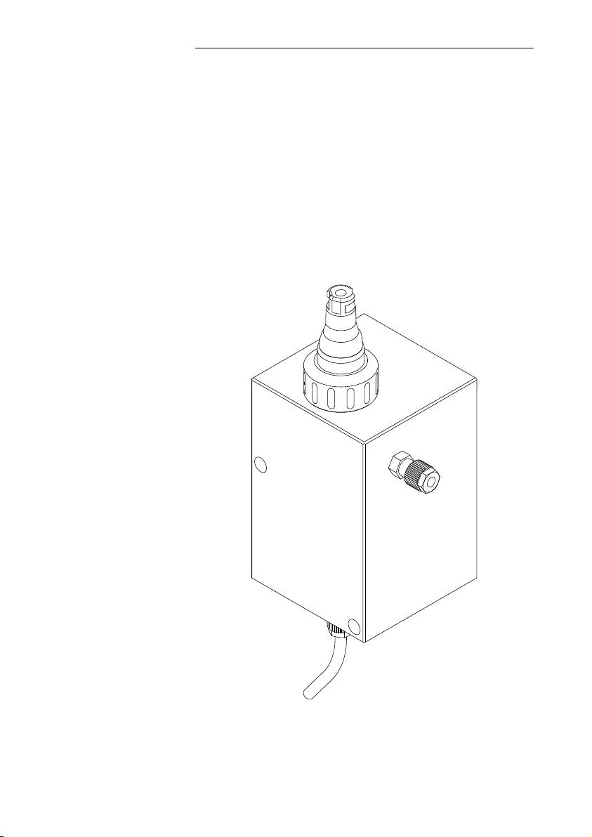
3 Product description
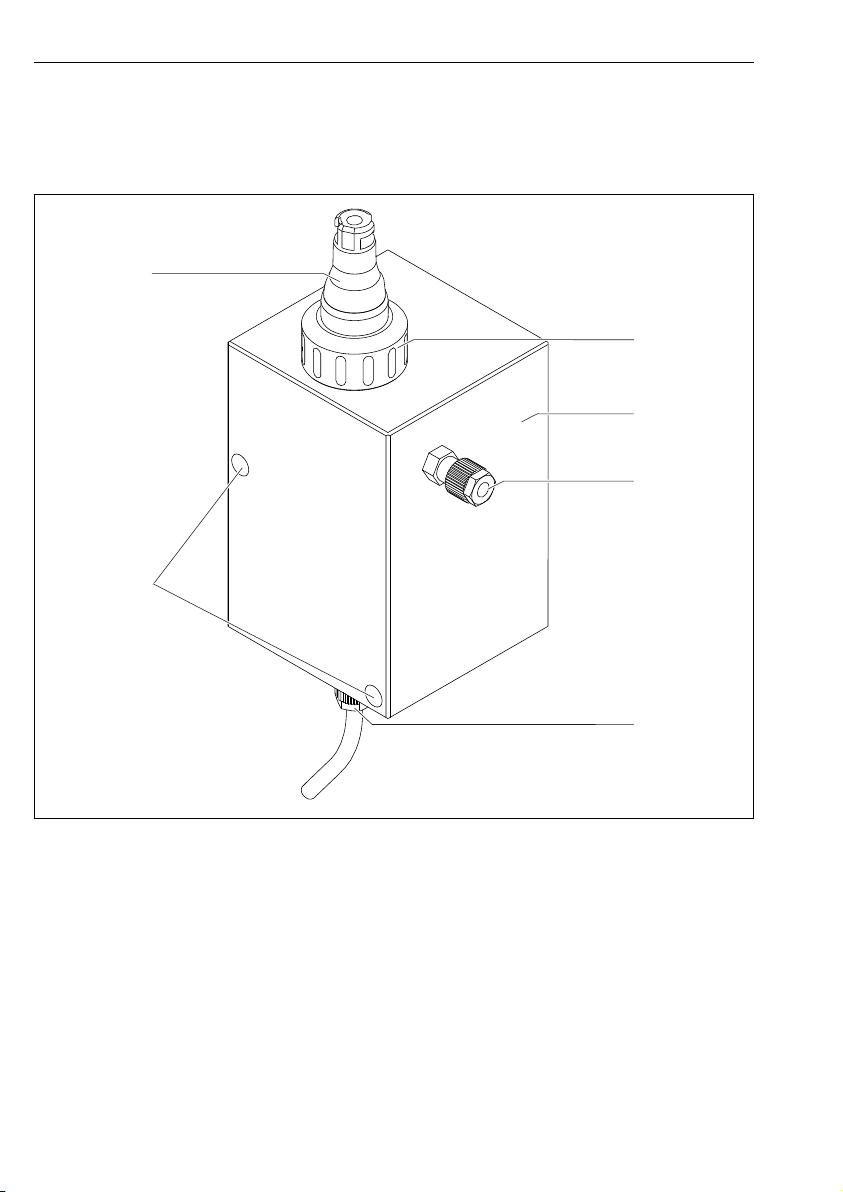
3.1 Product design
1 Disinfection sensor CCS5xD (membrane-covered, ⌀25 mm), e.g. CCS50D
2 Coupling nut (for securing a disinfection sensor)
3 Flowfit CCA151 flow assembly
4 Outlet from Flowfit CCA151 flow assembly (internal thread G 1/8") and hose connection
5 Inlet to Flowfit CCA151 flow assembly (internal thread G 1/8")
6 Openings (M5 Allen screw x 60) for securing Flowfit CCA151 flow assembly
8 Endress+Hauser
A0034257
Page 9

Flowfit CCA151 Incoming acceptance and product identification
4 Incoming acceptance and product identification
4.1 Incoming acceptance
1. Verify that the packaging is undamaged.
Notify the supplier of any damage to the packaging.
Keep the damaged packaging until the issue has been resolved.
2. Verify that the contents are undamaged.
Notify the supplier of any damage to the delivery contents.
Keep the damaged goods until the issue has been resolved.
3. Check that the delivery is complete and nothing is missing.
Compare the shipping documents with your order.
4. Pack the product for storage and transportation in such a way that it is protected
against impact and moisture.
The original packaging offers the best protection.
Make sure to comply with the permitted ambient conditions (→ Technical data).
If you have any questions, please contact your supplier or your local Sales Center.
Endress+Hauser 9
Page 10

Incoming acceptance and product identification Flowfit CCA151
4.2 Product identification
4.2.1 Nameplate
The nameplate provides you with the following information on your device:
• Manufacturer identification
• Order code
• Extended order code
• Serial number
• Ambient and process conditions
• Safety information and warnings
Compare the information on the nameplate with the order.
‣
4.2.2 Product identification
Product page
www.endress.com/cca151
Interpreting the order code
The order code and serial number of your product can be found in the following locations:
• On the nameplate
• In the delivery papers
Obtaining information on the product
1. Open the product website.
2. At the bottom of the page, select the link Online Tools and then select Access device
specific information .
An additional window opens.
3. Enter the order code from the nameplate into the search field. Then select Show
details .
Details of each feature (selected option) of the order code are displayed.
Manufacturer address
Endress+Hauser Conducta GmbH+Co. KG
Dieselstraße 24
D-70839 Gerlingen
Scope of delivery
The scope of delivery comprises:
• Assembly in the version ordered
• Operating Instructions
10 Endress+Hauser
Page 11

Flowfit CCA151 Installation
Certificates and approvals
RL 2014/34/EU (ATEX)
The assembly does not fall within the scope of the directive. However, if conditions for safe
use are adhered to, it may be deployed in the hazardous area.
RL 2014/68/EU PED
The assembly was manufactured in accordance with Article 3, paragraph 3, Pressure
Equipment Directive 97/23/EC in accordance with good engineering practice.
5 Installation
5.1 Installation conditions
5.1.1 Installation position
The assembly is designed for installation on panels, walls or level surfaces. G 1/8" connections
and a hose connection with an external diameter of 6 mm and an internal diameter of 4 mm
are provided for this purpose.
The assembly is designed in such a way that it must be installed vertically.
The sensor that is used can restrict the orientation.
Endress+Hauser 11
Page 12

Installation Flowfit CCA151
110 (4.33)
85 (3.35)
!14.5
(0.57)
7.5 (0.3)
70 (2.76)
70 (2.76)
105 (4.13)
130 (5.12)
150 (5.91)
194.5 (7.66)
M5 60·
M5 60·
150 (5.91)
219.5 (8.64)
! 25
(0.98)
! 14.5
(0.57)
! 39.5
(1.56)
5.1.2 Dimensions
1 Front view
To allow the sensor to be removed and for operation with Memosens data cables, the spacing
required for mounting is 150 mm (5.91 in).
12 Endress+Hauser
A0034258
Page 13

Flowfit CCA151 Installation
150 (5.91)
85 (3.35)
60 (2.36)
2 Side view
To allow the sensor to be removed and for operation with Memosens data cables, the spacing
required for mounting is 150 mm (5.91 in).
Endress+Hauser 13
A0034398
Page 14

Installation Flowfit CCA151
5.2 Mounting the assembly
5.2.1 Measuring system
A complete measuring system comprises:
• Disinfection sensor CCS50D (membrane-covered, ⌀25 mm) with corresponding installation
adapter
• Flowfit CCA151 flow assembly
• Measuring cable CYK10
• Transmitter, e.g. Liquiline CM44x or CM44xR
• Optional: Extension cable CYK11
14 Endress+Hauser
Page 15

Flowfit CCA151 Installation
1
3
6
8
2
7
4
5
A0034241
3 Example of a measuring system
1 Transmitter Liquiline CM44x
2 Power cable for transmitter
3 Disinfection sensor CCS5xD (membrane-covered, ⌀25 mm), e.g. CCS50D
4 Outlet from Flowfit CCA151 flow assembly
5 Inlet to Flowfit CCA151 flow assembly
6 Flowfit CCA151 flow assembly
7 Coupling nut for installing sensor CCS50D in Flowfit CCA151 flow assembly
8 Measuring cable CYK10
5.2.2 Mounting assembly on a vertical surface
To secure the assembly to a wall, use the wall mounting kit which can be ordered as an
‣
accessory→ 28.
For detailed information on mounting the assembly on a wall using the wall mounting
kit, see kit instructions for wall mounting kit
Endress+Hauser 15
Page 16

Installation Flowfit CCA151
5.2.3 Mounting assembly in the process
WARNING
L
Risk of injury from high pressure, high temperature or chemical hazards if process
medium escapes.
Wear protective gloves, protective goggles and protective clothing.
‣
Mount the assembly only if vessels or pipes are empty and unpressurized.
‣
Prior to installation, check the flange seal between the flanges.
1. Mount assembly on vertical surface→ 15.
2. Connect to the vessel or pipe via the process connection.
Bypass operation
To achieve flow through the assembly with a bypass, pressure p1 must be higher than
pressure p2.
This requires the installation of an orifice plate or throttle valve in the main pipe.
p1 must not exceed the permitted operating pressure for the assembly of 4 bar (58 psi).
If the sensor is installed, the sensor's pressure specifications must also be observed.
1. Mount the assembly vertically.
2. Connect the medium using the usual commercial connection fittings. Depending on
requirements, use the usual sealing materials, e.g. PMMA-compatible thread adhesive,
Teflon tape or O-ring made of FKM.
3. Installing the assembly in the bypass is preferable to installing it directly in the process
line. The bypass line can be blocked off without interrupting the process (a shut-off
valve is required upstream and downstream). This allows, for example, the sensor to be
cleaned without restricting the process.
4. Install a dirt trap (filter) with a mesh size of 500 μm upstream from the assembly. If a
pressure-reducing valve is used, it usually includes a dirt trap.
5. Set flow value upstream from the assembly, e. g. by installation of a flow setting.
6. Install a DN5-8 tap downstream from the assembly outlet to allow samples to be taken
for reference measurements in accordance with the DPD method.
16 Endress+Hauser
Page 17

Flowfit CCA151 Installation
1 2 3
4
p1
p2
p1 > p2
A0034259
4 Connection example with bypass and orifice plate in the main pipe
1 Shut-off valve (provided by customer)
2 Pressure-reducing valve (at p1 > 4 bar (58 psi)) (provided by customer)
3 Shut-off valve (provided by customer)
4 Orifice plate in process line (provided by customer)
Open outlet operation
p must not exceed the permitted operating pressure for the assembly of 4 bar (58 psi).
If the sensor is installed, the sensor's pressure specifications must also be observed.
If the medium pressure is above 4 bar (58 psi), a pressure-reducing valve is required.
1. Mount the assembly vertically.
2. Connect the medium using the usual commercial connection fittings. Depending on
requirements, use the usual sealing materials, e.g. PMMA-compatible thread adhesive,
Teflon tape or O-ring made of FKM.
3. Installing the assembly in the bypass is preferable to installing it directly in the process
line. The bypass line can be blocked off without interrupting the process (a shut-off
valve is required upstream and downstream). This allows, for example, the sensor to be
cleaned without restricting the process.
4. Install a dirt trap (filter) with a mesh size of 500 μm upstream from the assembly. If a
pressure-reducing valve is used, it usually includes a dirt trap.
5. Set flow value upstream from the assembly, e. g. by installation of a flow setting.
6. Install a DN5-8 tap downstream from the assembly outlet to allow samples to be taken
for reference measurements in accordance with the DPD method.
Endress+Hauser 17
Page 18

Installation Flowfit CCA151
1
2
3
p
A0034260
5 Connection example with open outlet
1 Shut-off valve (provided by customer)
2 Pressure-reducing valve (at p > 4 bar (58 psi)) (provided by customer)
3 Shut-off valve (provided by customer)
18 Endress+Hauser
Page 19

Flowfit CCA151 Installation
1
5.3 Installing sensor in assembly
The CCS50D disinfection sensor (membrane-covered, ⌀25 mm) is designed for installation in
the Flowfit CCA151 flow assembly.
Please note the following during installation:
The flow rate must be at least 5 l/h (1.32 gal/h).
‣
If the medium is fed back into an overflow basin, pipe or similar, the resulting
‣
counterpressure on the sensor may not exceed 1 bar (14.5 psi) and must remain constant.
Negative pressure at the sensor, e.g. due to medium being returned to the suction side of a
‣
pump, must be avoided.
Preparing assembly
1. The assembly is supplied to the customer with a coupling nut screwed onto the
assembly: unscrew coupling nut from assembly.
A0034262
6 Flowfit CCA151 flow assembly
1 Thread adapter nut
2. The assembly is supplied to the customer with a dummy plug inserted in the assembly:
remove dummy plug from assembly.
Endress+Hauser 19
Page 20

Installation Flowfit CCA151
Removing protection cap from sensor
NOTICE
Negative pressure causes damage to the sensor's membrane cap.
If the protection cap is attached, carefully remove protection cap from sensor.
‣
1. When supplied to the customer and when in storage, the sensor is fitted with a
protection cap: First release just the top part of the protection cap by turning it.
A0034263
7 Releasing top part of protection cap by turning
2. Carefully remove protection cap from sensor.
A0034350
8 Carefully remove protection cap.
20 Endress+Hauser
Page 21

Flowfit CCA151 Installation
Fit the adapter to the sensor.
The required adapter (clamping ring) can be ordered as a sensor accessory or as a separate
accessory.
1. Slide the adapter for CCA151 (clamping ring) from the membrane cap towards the
sensor head and into the lower groove.
A0034247
9 Slide the adapter (clamping ring) upwards from the membrane camp to the senor
shaft and into the lower groove.
Installing sensor in assembly
2. Slide the sensor with adapter for CCA151 (clamping ring) into the opening in the
assembly.
Endress+Hauser 21
Page 22

Commissioning Flowfit CCA151
1
2
3
3. Screw coupling nut onto assembly on block.
A0034261
1 Disinfection sensor CCS50D
2 Flowfit CCA151 flow assembly
3 Coupling nut for securing a CCS50D disinfection sensor
5.4 Post-installation check
1. After mounting, check all connections to ensure they are fully secured and leak-tight.
2. Check all hoses for damage.
6 Commissioning
Prior to commissioning, ensure that:
• all seals are correctly seated (on the assembly and on the process connection)
• the sensor is correctly installed and connected
WARNING
L
Risk of injury from high pressure, high temperature or chemical hazards if process
medium escapes.
Before subjecting the assembly to the process pressure, verify that all connections are
‣
sealed.
22 Endress+Hauser
Page 23

Flowfit CCA151 Maintenance
7 Maintenance
WARNING
L
Risk of injury if medium escapes
Before each maintenance task, ensure that the process pipe is empty and rinsed.
‣
7.1 Maintenance schedule
The specified intervals serve as a guide. For harsh process or ambient conditions, it is
recommended that the interval be shortened accordingly. Cleaning intervals for the
sensor and assembly are dependent on the medium.
Interval Maintenance work
Monthly
Biannually
Verify that process connections are leak-tight.
‣
1. Remove sensor and check for deposits.
2. If deposits are present, check cleaning cycle (cleaning agents,
temperature, duration, flow volume).
Replace seals in contact with medium.
‣
Endress+Hauser 23
Page 24

Maintenance Flowfit CCA151
7.2 Maintenance tasks
To ensure stable and reliable measurements, the assembly and the sensor must be cleaned
regularly. The frequency and intensity of the cleaning process depend on the medium.
7.2.1 Cleaning the assembly
A typical example of a cleaning interval would be 6 months in the case of drinking water.
1. All parts in contact with the medium, such as the sensor and the sensor guide, must be
cleaned regularly. To do so, remove the sensor → 26.
2. Remove light dirt and fouling using a cloth moistened with suitable cleaning solutions.
3. Remove heavy soiling using a soft brush and a suitable cleaning agent.
4. For very persistent dirt, soak the parts in a cleaning solution. Then clean the parts with
a brush.
24 Endress+Hauser
Page 25

Flowfit CCA151 Maintenance
Cleaning agent
The choice of cleaning agent depends on the degree and type of contamination. The most
common types of contamination and the appropriate cleaning agents can be found in the
following table.
Type of soiling Cleaning agent
Greases and oils Hot water or water-soluble organic solvents (e.g.
ethanol)
Limescale deposits, metal
Approx. 3% hydrochloric acid
hydroxide buildup, lyophobic
biological buildup
Sulfide deposits Mixture of 3% hydrochloric acid and thiocarbamide
(commercially available)
Protein buildup Mixture of 3% hydrochloric acid and pepsin
(commercially available)
Fibers, suspended substances Pressurized water, possibly surface-active agents
Light biological buildup Pressurized water
NOTICE
Health hazard due to solvents
Do not use any halogen-containing, organic solvents or acetone. These solvents may
‣
destroy plastic components of the sensor and are also suspected carcinogens (e.g.
chloroform).
NOTICE
Damage to sensor membrane
The sensor membrane must not come into contact with surfactant-containing agents.
‣
7.2.2 Cleaning the sensor
Cleaning the sensor
1. Prior to calibration if dirt is visible on the surface
2. Regularly during operation
3. Before returning it for repairs
For detailed information on "Cleaning the sensor", see Operating Instructions for sensor.
Endress+Hauser 25
Page 26

Maintenance Flowfit CCA151
1
2
3
7.2.3 Removing sensor from assembly
Remove sensor from assembly CCA151
1. Unscrew coupling nut from assembly.
A0034261
1 Disinfection sensor CCS50D
2 Flowfit CCA151 flow assembly
3 Coupling nut for securing a CCS50D disinfection sensor
2. Pull sensor out through opening in assembly.
26 Endress+Hauser
Page 27

Flowfit CCA151 Repairs
8 Repairs
WARNING
L
Danger resulting from improper repair
Damage to the assembly, which compromises pressure safety, must be repaired only by
‣
authorized and qualified personnel.
Following each repair and maintenance task, the assembly must be checked for leaks using
‣
appropriate procedures. Following this, the assembly must again comply with the
specifications in the technical data.
Replace all other damaged components immediately.
8.1 Spare parts
For more detailed information on spare parts kits, please refer to the "Spare Part Finding Tool"
on the Internet:
www.endress.com/spareparts_consumables
Description and contents Order No.
Kit CCA151, complete with blind plug
• Blind plug with O-ring
• Screw plug
8.2 Return
The product must be returned if repairs or a factory calibration are required, or if the wrong
product was ordered or delivered. As an ISO-certified company and also due to legal
regulations, Endress+Hauser is obliged to follow certain procedures when handling any
returned products that have been in contact with medium.
71372020
To ensure the swift, safe and professional return of the device:
Refer to the website www.endress.com/support/return-material for information on the
‣
procedure and conditions for returning devices.
8.3 Disposal
The device contains electronic components. and must therefore be disposed of in accordance
with regulations on the disposal of electronic waste.
Observe the local regulations.
‣
Endress+Hauser 27
Page 28

Accessories Flowfit CCA151
9 Accessories
The following are the most important accessories available at the time this documentation
was issued.
For accessories not listed here, please contact your Service or Sales Center.
‣
9.1 Device-specific accessories
9.1.1 Disinfection sensor CCS50D
• Membrane-covered amperometric sensor for chlorine dioxide
• With Memosens technology
• Product Configurator on the product page: www.endress.com/ccs50d
Technical Information TI01353C
9.1.2 Wall mounting kit
Wall mounting kit for CCA151
Order No. 71372109
10 Technical data
10.1 Environment
10.1.1 Ambient temperature range
-20 to +60 °C (-4 to 140 °F)
10.1.2 Storage temperature
-20 to +60 °C (-4 to 140 °F)
10.2 Process
10.2.1 Process temperature
0 to 60 °C (32 to 140 °F), non-freezing
10.2.2 Process pressure
0 to 4 bar (0 to 58 psi) relative
28 Endress+Hauser
Page 29

Flowfit CCA151 Technical data
p [bar]
T[°C]
20 60
40
T[°F]
p [psi]
0
32
0
0
68 104 140
4
58
10.2.3 Pressure-temperature ratings
A0034376-EN
10 Pressure-temperature ratings
10.2.4 Process connections
G1/8"
Hose specification: External diameter 6 mm, internal diameter 4 mm
10.2.5 Flow
remains stable for a minimum of 5 l/h (1.32 gal/hr) when using 25 mm (0.98 in) disinfection
sensors with approx. 77 mm (3.03 in) immersion depth
Endress+Hauser 29
Page 30

Technical data Flowfit CCA151
10.3 Mechanical construction
→ 12
10.3.1 Weight
1.077 kg (2.37 lbs)
10.3.2 Materials
In contact with medium
Assembly: PMMA
Seals: PVDF
Dummy plug: PVC, FKM
30 Endress+Hauser
Page 31

Flowfit CCA151 Index
Index
A
Accessories ..................... 28
Approvals ...................... 11
C
Certificates ..................... 11
Cleaning agent ................... 25
Commissioning ...................22
D
Designated use ....................6
Dimensions ..................... 12
Disposal ....................... 27
I
Incoming acceptance ................ 9
Installation ................... 11, 14
Installation conditions ...............11
Installing the sensor ................19
M
Maintenance .................... 23
Maintenance schedule ...............23
Maintenance tasks .................24
Measuring system ................. 14
N
Nameplate ..................... 10
U
Use ...........................6
W
Warnings ....................... 4
P
Post-installation check .............. 22
Product identification ................ 9
R
Repairs ........................27
Return ........................ 27
S
Safety instructions ..................6
Scope of delivery .................. 10
Spare parts ..................... 27
Symbols ........................ 4
T
Technical data ................... 28
Endress+Hauser 31
Page 32

*71371624*
71371624
 Loading...