

Page 1
TI01357C/07/EN/01.17
71371626
Products Solutions Services
Technical Information
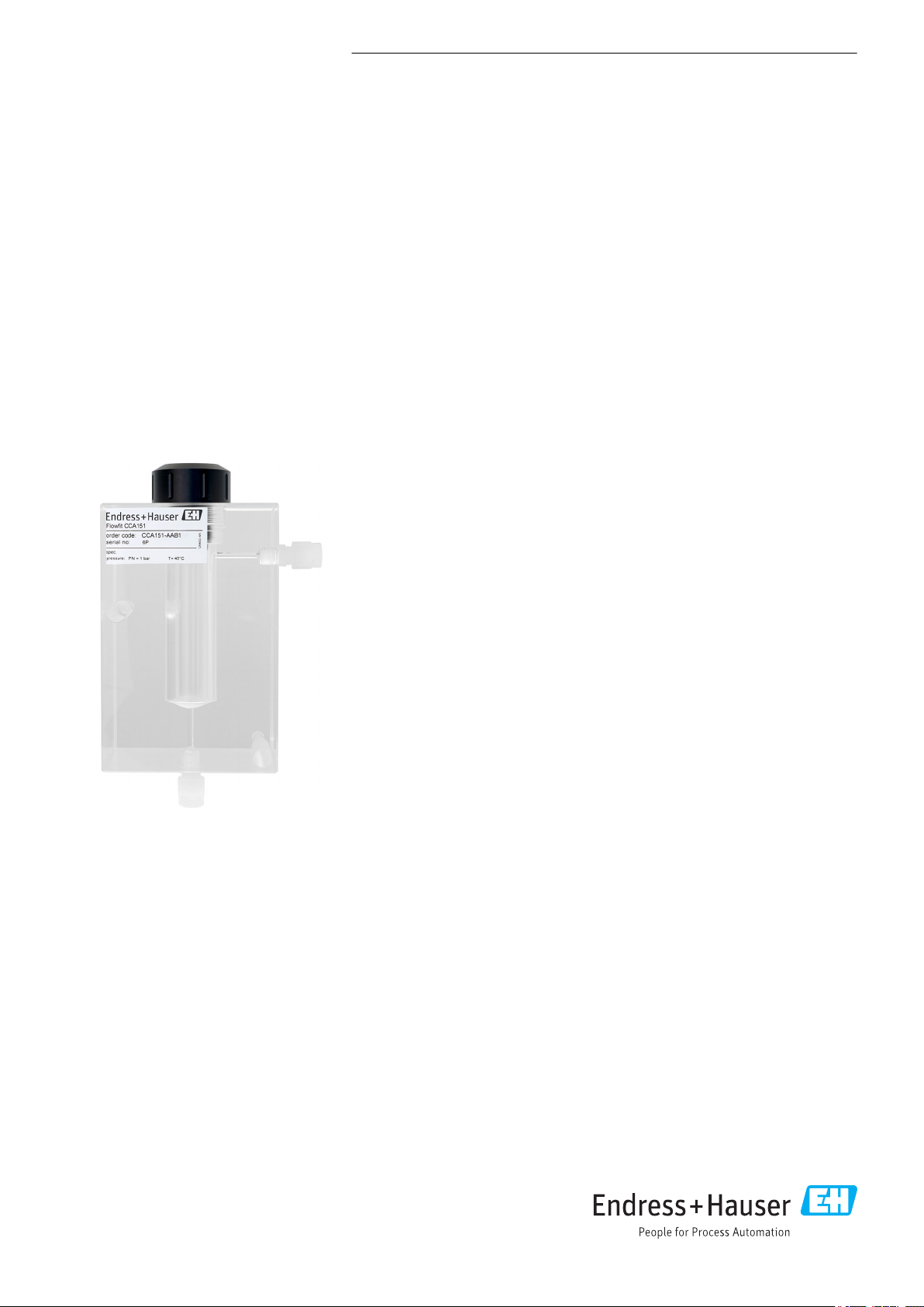
Flowfit CCA151
Flow assembly for disinfection sensors CCS5xD
Simple assembly for measuring disinfection in
drinking and process water
Application
• Drinking water
• Utilities in all sectors
• Applications with low sample volumes
Your benefits
• Suitable for all disinfection processes without pH compensation - chlorine dioxide
and others
• Requires only low sample flow: At least 5 l/h (1.32 gal/h)
• A new addition to the flow assembly range: Same form as and can be exchanged
for CCA250
Page 2
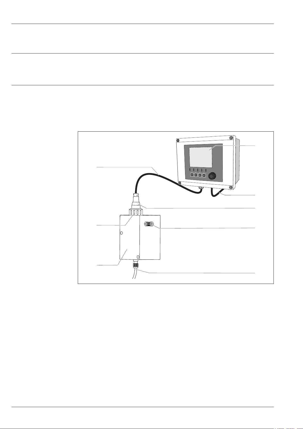
Function and system design
1
3
6
8
2
7
4
5
Flowfit CCA151
Mode of operation
Measuring system
You can carry out reliable chlorine dioxide measurements using suitable sensors with flow assembly
CCA151 . You can remove, clean, sterilize or calibrate/adjust the sensors without interrupting the
process.
The assembly can be installed in both vessels and pipes.
A complete measuring system comprises:
• Disinfection sensor CCS50D (membrane-covered, ⌀25 mm) with corresponding installation
adapter
• Flowfit CCA151 flow assembly
• Measuring cable CYK10
• Transmitter, e.g. Liquiline CM44x or CM44xR
• Optional: Extension cable CYK11
1 Example of a measuring system
1 Transmitter Liquiline CM44x
2 Power cable for transmitter
3 Disinfection sensor CCS5xD (membrane-covered, ⌀25 mm), e.g. CCS50D
4 Outlet from Flowfit CCA151 flow assembly
5 Inlet to Flowfit CCA151 flow assembly
6 Flowfit CCA151 flow assembly
7 Coupling nut for installing sensor CCS50D in Flowfit CCA151 flow assembly
8 Measuring cable CYK10
2 Endress+Hauser
A0034241
Page 3

Flowfit CCA151
Installation
Orientation
Installation instructions
The assembly is designed for installation on panels, walls or level surfaces. G 1/8" connections and a
hose connection with an external diameter of 6 mm and an internal diameter of 4 mm are provided
for this purpose.
The assembly is designed in such a way that it must be installed vertically.
The sensor that is used can restrict the orientation.
WARNING
L
Risk of injury from high pressure, high temperature or chemical hazards if process medium
escapes.
Wear protective gloves, protective goggles and protective clothing.
‣
Mount the assembly only if vessels or pipes are empty and unpressurized.
‣
Prior to installation, check the flange seal between the flanges.
1. Mount assembly on vertical surface.
2. Connect to the vessel or pipe via the process connection.
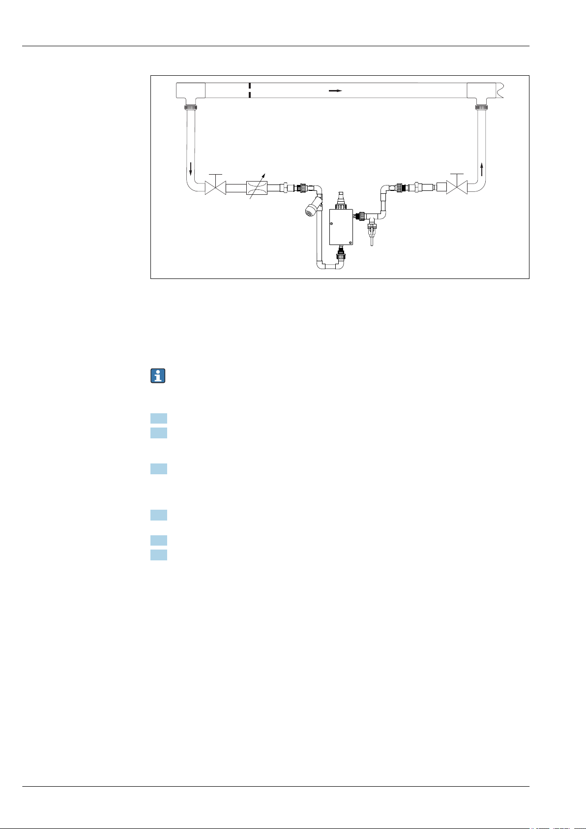
Bypass operation
To achieve flow through the assembly with a bypass, pressure p1 must be higher than pressure p2.
This requires the installation of an orifice plate or throttle valve in the main pipe.
p1 must not exceed the permitted operating pressure for the assembly of 4 bar (58 psi).
If the sensor is installed, the sensor's pressure specifications must also be observed.
1. Mount the assembly vertically.
2. Connect the medium using the usual commercial connection fittings. Depending on
requirements, use the usual sealing materials, e.g. PMMA-compatible thread adhesive, Teflon
tape or O-ring made of FKM.
3. Installing the assembly in the bypass is preferable to installing it directly in the process line.
The bypass line can be blocked off without interrupting the process (a shut-off valve is required
upstream and downstream). This allows, for example, the sensor to be cleaned without
restricting the process.
4. Install a dirt trap (filter) with a mesh size of 500 μm upstream from the assembly. If a
pressure-reducing valve is used, it usually includes a dirt trap.
5. Set flow value upstream from the assembly, e. g. by installation of a flow setting.
6. Install a DN5-8 tap downstream from the assembly outlet to allow samples to be taken for
reference measurements in accordance with the DPD method.
Endress+Hauser 3
Page 4
1 2 3
4
p1
p2
p1 > p2
2 Connection example with bypass and orifice plate in the main pipe
1 Shut-off valve (provided by customer)
2 Pressure-reducing valve (at p1 > 4 bar (58 psi)) (provided by customer)
3 Shut-off valve (provided by customer)
4 Orifice plate in process line (provided by customer)
Flowfit CCA151
A0034259
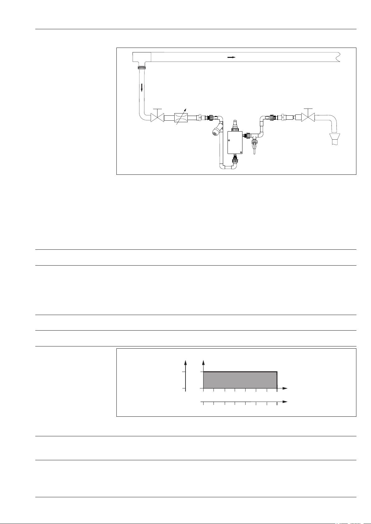
Open outlet operation
p must not exceed the permitted operating pressure for the assembly of 4 bar (58 psi).
If the sensor is installed, the sensor's pressure specifications must also be observed.
If the medium pressure is above 4 bar (58 psi), a pressure-reducing valve is required.
1. Mount the assembly vertically.
2. Connect the medium using the usual commercial connection fittings. Depending on
requirements, use the usual sealing materials, e.g. PMMA-compatible thread adhesive, Teflon
tape or O-ring made of FKM.
3. Installing the assembly in the bypass is preferable to installing it directly in the process line.
The bypass line can be blocked off without interrupting the process (a shut-off valve is required
upstream and downstream). This allows, for example, the sensor to be cleaned without
restricting the process.
4. Install a dirt trap (filter) with a mesh size of 500 μm upstream from the assembly. If a
pressure-reducing valve is used, it usually includes a dirt trap.
5. Set flow value upstream from the assembly, e. g. by installation of a flow setting.
6. Install a DN5-8 tap downstream from the assembly outlet to allow samples to be taken for
reference measurements in accordance with the DPD method.
4 Endress+Hauser
Page 5
Flowfit CCA151
1
2
3
p
p [bar]
T[°C]
20 60
40
T[°F]
p [psi]
0
32
0
0
68 104 140
4
58
A0034260
3 Connection example with open outlet
1 Shut-off valve (provided by customer)
2 Pressure-reducing valve (at p > 4 bar (58 psi)) (provided by customer)
3 Shut-off valve (provided by customer)
Environment
Ambient temperature
Storage temperature
-20 to +60 °C (-4 to 140 °F)
-20 to +60 °C (-4 to 140 °F)
Process
Process temperature range
Process pressure range
Pressure temperature load curve
0 to 60 °C (32 to 140 °F), non-freezing
0 to 4 bar (0 to 58 psi) relative
A0034376-EN
4 Pressure-temperature ratings
Process connections
G1/8"
Hose specification: External diameter 6 mm, internal diameter 4 mm
Flow
Endress+Hauser 5
remains stable for a minimum of 5 l/h (1.32 gal/hr) when using 25 mm (0.98 in) disinfection
sensors with approx. 77 mm (3.03 in) immersion depth
Page 6

Dimensions
110 (4.33)
85 (3.35)
!14.5
(0.57)
7.5 (0.3)
70 (2.76)
70 (2.76)
105 (4.13)
130 (5.12)
150 (5.91)
194.5 (7.66)
M5 60·
M5 60·
150 (5.91)
219.5 (8.64)
! 25
(0.98)
! 14.5
(0.57)
! 39.5
(1.56)
Flowfit CCA151
Mechanical construction
A0034258
5 Front view
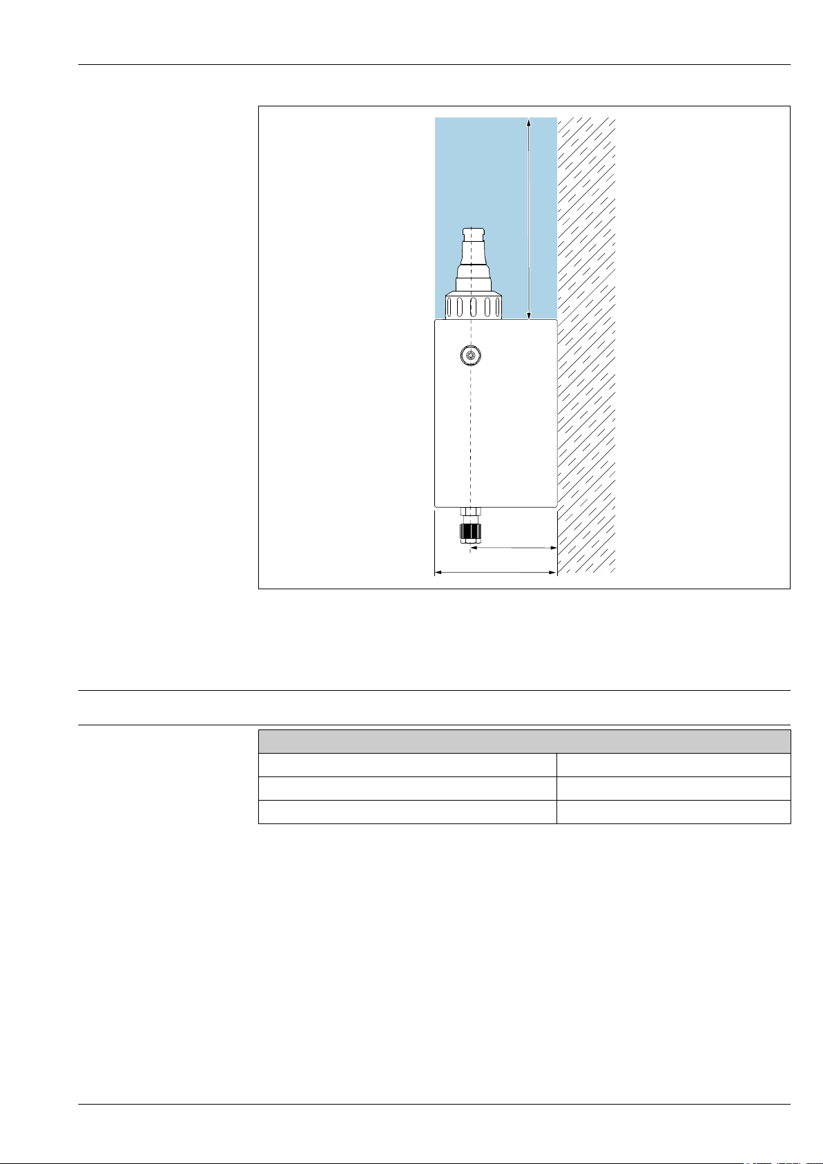
To allow the sensor to be removed and for operation with Memosens data cables, the spacing
required for mounting is 150 mm (5.91 in).
6 Endress+Hauser
Page 7
Flowfit CCA151
150 (5.91)
85 (3.35)
60 (2.36)
Weight
Materials
A0034398
6 Side view
To allow the sensor to be removed and for operation with Memosens data cables, the spacing
required for mounting is 150 mm (5.91 in).
1.077 kg (2.37 lbs)
In contact with medium
Assembly: PMMA
Seals: PVDF
Dummy plug: PVC, FKM
Certificates and approvals
RL 2014/34/EU (ATEX)
The assembly does not fall within the scope of the directive. However, if conditions for safe use are
adhered to, it may be deployed in the hazardous area.
RL 2014/68/EU PED
The assembly was manufactured in accordance with Article 3, paragraph 3, Pressure Equipment
Directive 97/23/EC in accordance with good engineering practice.
Endress+Hauser 7
Page 8

Ordering information
Flowfit CCA151
Product page
Product Configurator
Scope of delivery
www.endress.com/cca151
On the product page there is a "Configure" button to the right of the product image Configure.
1. Click this button.
The Configurator opens in a separate window.
2. Select all the options to configure the device in line with your requirements.
In this way, you receive a valid and complete order code for the device.
3. Export the order code as a PDF or Excel file. To do so, click the appropriate button on the right
above the selection window.
For many products you also have the option of downloading CAD or 2D drawings of the
selected product version. Click the tab for this CAD and select the desired file type using
picklists.
The scope of delivery comprises:
• Assembly in the version ordered
• Operating Instructions
Accessories
The following are the most important accessories available at the time this documentation was
issued.
For accessories not listed here, please contact your Service or Sales Center.
‣
Device-specific accessories Disinfection sensor
CCS50D
• Membrane-covered amperometric sensor for chlorine dioxide
• With Memosens technology
• Product Configurator on the product page: www.endress.com/ccs50d
Technical Information TI01353C
Wall mounting kit
Wall mounting kit for CCA151
Order No. 71372109
8 Endress+Hauser
Page 9

Page 10

Page 11

Page 12

www.addresses.endress.com
 Loading...