

Page 1
BA00459C/07/EN/15.19
71447513
2019-01-31
Products Solutions Services
Operating Instructions
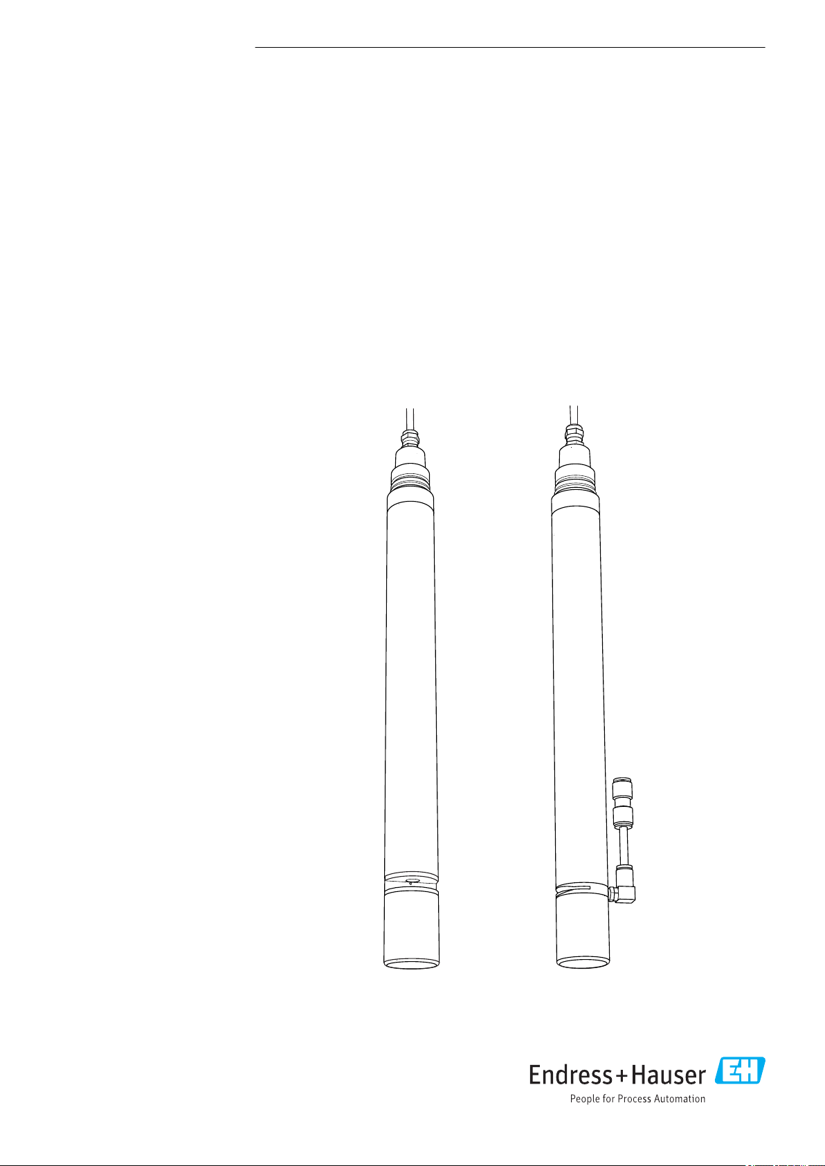
Viomax CAS51D
Photometric sensor for SAC or nitrate measurement
Page 2

Table of contents Viomax CAS51D
Table of contents
1 About this document ................ 3
1.1 Warnings ............................ 3
1.2 Symbols used .......................... 3
1.3 Symbols on the device ................... 3
2 Basic safety instructions ............ 4
2.1 Requirements for the personnel ............ 4
2.2 Designated use ........................ 4
2.3 Workplace safety ....................... 4
2.4 Operational safety ...................... 5
2.5 Product safety ......................... 5
3 Device description .................. 6
3.1 Sensor design ......................... 6
3.2 Dimensions ........................... 6
3.3 Operating principle ..................... 8
4 Incoming acceptance and product
identification ..................... 11
4.1 Incoming acceptance ................... 11
4.2 Product identification ................... 11
4.3 Scope of delivery ...................... 12
4.4 Certificates and approvals ............... 12
10 Repairs ........................... 37
10.1 Return .............................. 37
10.2 Disposal ............................ 37
11 Accessories ....................... 38
11.1 Assemblies .......................... 38
11.2 Holder .............................. 38
11.3 Compressed air cleaning ................ 38
11.4 Standard solutions ..................... 39
12 Technical data .................... 40
12.1 Input ............................... 40
12.2 Performance characteristics .............. 41
12.3 Environment ......................... 42
12.4 Process ............................. 42
12.5 Mechanical construction ................ 42
Index .................................. 43
5 Mounting ......................... 13
5.1 Installation conditions .................. 13
5.2 Mounting the sensor ................... 14
5.3 Immersion operation ................... 15
5.4 Flow operation ....................... 17
5.5 Mounting the cleaning unit .............. 22
5.6 Post-installation check .................. 23
6 Electrical connection .............. 24
6.1 Connecting to the transmitter ............ 24
6.2 Ensuring the degree of protection .......... 25
6.3 Post-connection check .................. 25
7 Operation ......................... 26
7.1 Calibration .......................... 26
7.2 Cyclic cleaning ........................ 35
8 Diagnostics and troubleshooting ... 35
9 Maintenance ...................... 36
9.1 Maintenance intervals .................. 36
9.2 Cleaning the sensor .................... 36
9.3 Maintenance of optical filters and strobe
lamp ............................... 37
2 Endress+Hauser
Page 3
Viomax CAS51D About this document
1 About this document
1.1 Warnings
Structure of information Meaning
DANGER
L
Causes (/consequences)
If necessary, Consequences of
non-compliance (if applicable)
Corrective action
‣
WARNING
L
Causes (/consequences)
If necessary, Consequences of
non-compliance (if applicable)
Corrective action
‣
CAUTION
L
Causes (/consequences)
If necessary, Consequences of
non-compliance (if applicable)
Corrective action
‣
NOTICE
Cause/situation
If necessary, Consequences of
non-compliance (if applicable)
Action/note
‣
This symbol alerts you to a dangerous situation.
Failure to avoid the dangerous situation will result in a fatal or serious
injury.
This symbol alerts you to a dangerous situation.
Failure to avoid the dangerous situation can result in a fatal or serious
injury.
This symbol alerts you to a dangerous situation.
Failure to avoid this situation can result in minor or more serious injuries.
This symbol alerts you to situations which may result in damage to
property.
1.2 Symbols used
Symbol Meaning
Additional information, tips
Permitted or recommended
Not permitted or not recommended
Reference to device documentation
Reference to page
Reference to graphic
Result of a step
1.3 Symbols on the device
Symbol Meaning
Reference to device documentation
Endress+Hauser 3
Page 4

Basic safety instructions Viomax CAS51D
2 Basic safety instructions
2.1 Requirements for the personnel
• Installation, commissioning, operation and maintenance of the measuring system may
be carried out only by specially trained technical personnel.
• The technical personnel must be authorized by the plant operator to carry out the
specified activities.
• The electrical connection may be performed only by an electrical technician.
• The technical personnel must have read and understood these Operating Instructions
and must follow the instructions contained therein.
• Faults at the measuring point may only be rectified by authorized and specially trained
personnel.
Repairs not described in the Operating Instructions provided must be carried out only
directly at the manufacturer's site or by the service organization.
2.2 Designated use
CAS51D is a photometric sensor for SAC or nitrate measurement in liquid media.
The sensor is particularly suited for use in the following applications:
• Monitoring and regulating water treatment plants
• Monitoring surface waters
SAC measurement
• Organic load in WWTP inlet
• Organic load WWTP outlet
• Discharger monitoring
• Organic load in drinking water
Nitrate measurement
• Nitrate measurement in natural bodies of water
• Monitoring nitrate content in WWTP outlet
• Monitoring nitrate content in aeration basins
• Monitoring and optimizing denitrification phases
Use of the device for any purpose other than that described, poses a threat to the safety of
people and of the entire measuring system and is therefore not permitted.
The manufacturer is not liable for damage caused by improper or non-designated use.
2.3 Workplace safety
CAUTION
L
UV light
UV light can damage the eyes!
Never look into the cuvette gap while the sensor is in operation.
‣
As the user, you are responsible for complying with the following safety conditions:
• Installation guidelines
• Local standards and regulations
Electromagnetic compatibility
• The product has been tested for electromagnetic compatibility in accordance with the
applicable international standards for industrial applications.
• The electromagnetic compatibility indicated applies only to a product that has been
connected in accordance with these Operating Instructions.
4 Endress+Hauser
Page 5

Viomax CAS51D Basic safety instructions
2.4 Operational safety
Before commissioning the entire measuring point:
1. Verify that all connections are correct.
2. Ensure that electrical cables and hose connections are undamaged.
3. Do not operate damaged products, and protect them against unintentional operation.
4. Label damaged products as defective.
During operation:
If faults cannot be rectified:
‣
products must be taken out of service and protected against unintentional operation.
2.5 Product safety
The product is designed to meet state-of-the-art safety requirements, has been tested, and
left the factory in a condition in which it is safe to operate. The relevant regulations and
international standards have been observed.
Endress+Hauser 5
Page 6
Device description Viomax CAS51D
50
(1.97)
40 (1.57)
388 (15.28)
78 (3.07)
NPT “¾
G1
2 (0.08)
8 (0.31)
12 (0.47)
20 (0.79)
14.5 (0.57)
NPT “¾
G1
78 (3.07)
394 (15.51)
8 (0.31)
40 (1.57)
14 (0.55)
20 (0.79)
12 (0.47)
14.5 (0.57)
3 Device description
3.1 Sensor design
The sensor has a diameter of 40 mm and can be operated directly and completely in the
process without the need for further sampling (in situ). One version of the sensor
measures the amount of nitrate in the medium while another version measures the SAC
value of the medium.
The sensor comprises the following assemblies:
• Power supply
• High-voltage generation for the strobe lamp,
• Cuvette
Central component in which the measuring light interacts with the medium.
• Receiver assembly
Detect the measuring signals, digitize them and process them to form a measured value.
• Controller
Responsible for controlling internal sensor processes and transmitting data.
All data - including the calibration data - are stored in the sensor. The sensor can be
precalibrated and used at a measuring point, calibrated externally, or used for several
measuring points with different calibrations.
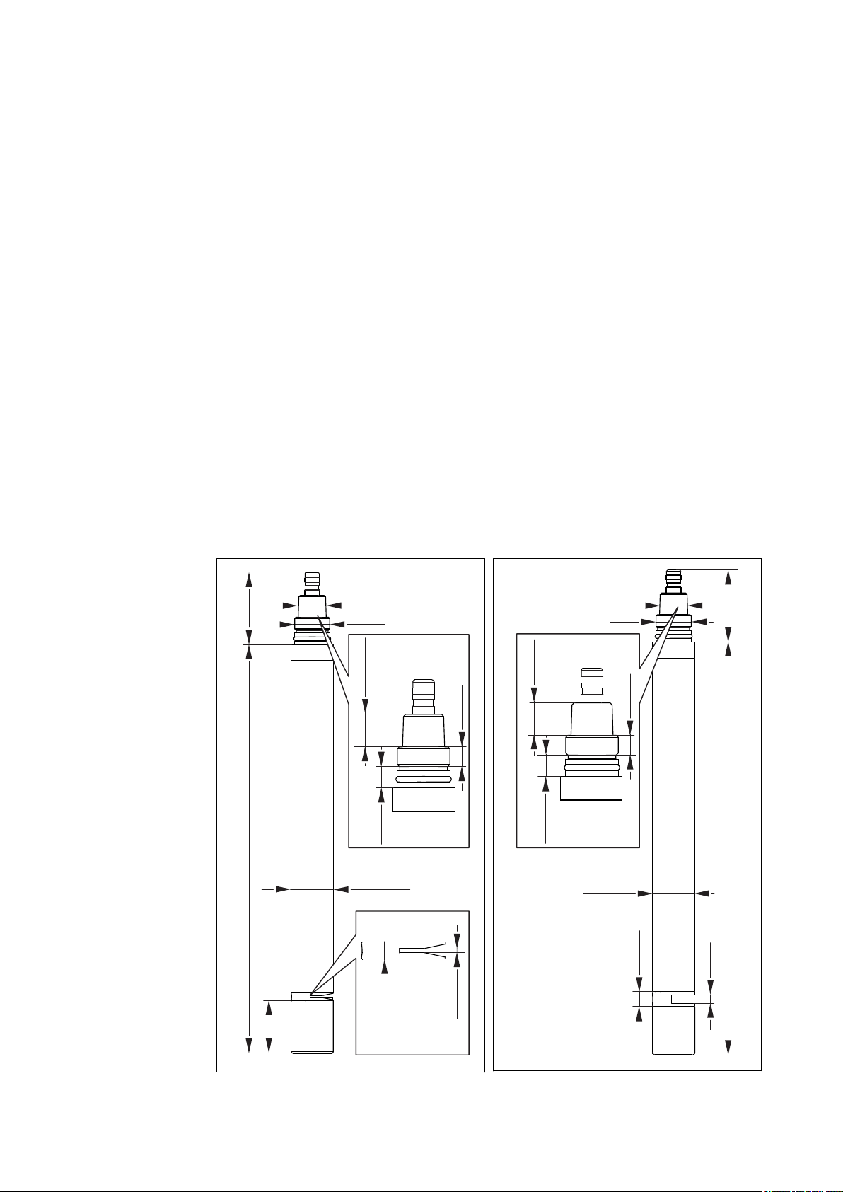
3.2 Dimensions
6 Endress+Hauser
1 Sensor with 2 mm gap width, dimensions in
mm (inch)
A0013193
2 Sensor with 8 mm gap width, dimensions in
mm (inch)
A0013208
Page 7

Viomax CAS51D Device description
20 (0.79)
12 (0.47)
14.5 (0.57)
40 (1.57)
NPT “¾
G1
69 (2.72)
40 (1.57)
46 (1.81)
426 (16.77)
A0031311
3 Sensor with 40 mm gap width, dimensions in
mm (inch)
Endress+Hauser 7
Page 8

Device description Viomax CAS51D
1
2
3
4
56
3.3 Operating principle
3.3.1 Measuring principle
The light from a pulsed, high-stability strobe lamp (item 3) passes through the measuring
1)
path
1 and 5). A filter upstream from the receivers only lets through light in the measuring
wavelength or reference wavelength.
(item 2). A beam splitter (item 6) directs the light beam to the two receivers (items
A0013213
4 Measuring principle of nitrate sensor
1 Measuring receiver with filter
2 Cuvette gap
3 Strobe lamp
4 Lens
5 Reference receiver with filter
6 Beam splitter
Within the measuring path, the medium in the cuvette (water, dissolved substances and
particles) absorbs light across the entire spectrum. In the measuring wavelength range, the
measured component
2)
takes an additional amount of energy from the light.
For the calculation of the measured value, the ratio of the light signal of the measuring
wavelength to the light signal of the reference wavelength is calculated in order to
minimize the effect of turbidity and lamp aging.
This change in the ratio can be converted to determine the nitrate concentration or the
SAC value. This dependency is non-linear.
Conclusion:
• Long measuring paths are required for low concentrations of the measured component.
For clear water measurements, this is achieved with the 8 mm cuvette for nitrate
measurement and the 40 mm cuvette for SAC measurement.
• For high turbidity values, longer measuring paths result in the total absorption of light the measured values are no longer valid.
The nitrate sensor with the 2 mm cuvette is recommended for media with high turbidity
values (activated sludge application).
The SAC sensor with the 2 mm cuvette is ideal for measuring the organic load in the
inlet of municipal wastewater treatment plants.
1) Measuring path = open path through cuvette
2) Nitrate or substances that contribute to the spectral absorption coefficient (SAC)
8 Endress+Hauser
Page 9

Viomax CAS51D Device description
3.3.2 Nitrate measurement
The sensor is designed for measuring nitrate. As nitrite is also measured, it could also be
regarded as an NOx sensor.
Nitrate ions absorb UV light in the range of approx. 190 to 230 nm. Nitrite ions have a
similar absorption rate in the same range.
The sensor measures the light intensity of the 214 nm wavelength (measuring channel).
At this wavelength, nitrate and nitrite ions absorb light in proportion to their
concentration, while the light intensity in the reference channel remains virtually
unchanged at 254 nm.
Interference factors, such as turbidity, fouling or organic hydrocarbons, are minimized.
The signal ratio between the reference wavelength and measurement wavelength
constitutes the measurement result. This ratio is converted to the concentration of nitrate
using the calibration curve programmed into the sensor.
3.3.3 Cross-interference when measuring with the nitrate version
The following have a direct impact on the measuring range:
• Total solids (TS) and turbidity
• Sludge properties
• Nitrite
Trends:
• A higher proportion of TS or greater turbidity reduces the upper end of the measuring
range, resulting in a smaller measuring range.
• High COD
measuring range.
• Nitrite is measured as nitrate, thus resulting in a higher measured value.
The following can be deduced from the interdependencies cited above:
• Sludge floc causes scattering in the medium, resulting in the attenuation of both the
measuring and reference signal to varying degrees. This in turn can bring about a
change in the nitrate value due to turbidity.
• High concentrations of oxidizable substances
in the measured value.
• Nitrite absorbs light in a similar wavelength range to nitrate and is measured along with
nitrate. The dependency is constant: 1.0 mg/l nitrite is displayed as 0.8 mg/l nitrate.
• An adjustment to the customer process is always worthwhile.
3)
levels reduce the upper end of the measuring range, resulting in a smaller
4)
in the medium may result in an increase
3.3.4 SAC measurement
Many organic substances absorb light in the range of 254 nm. In the SAC sensor,
absorption on the measuring wavelength (254 nm) is compared with the largely
unaffected reference measurement at 550 nm.
KHP (potassium hydrogen phthalate C8H5KO4) is the established organic reference in SAC
measurement operations. That is why the sensor is calibrated in the factory using KHP.
The SAC value can be regarded as a trend indicator of the organic load in a medium. For
this purpose, it is converted to COD, TOC, BOD and DOC
factors:
c (TOC) = 0.4705 * c (KHP)
c (COD) = 1.176 * c (KHP)
c (BOD) = 1.176 * c (KHP)
c (DOC) = 0.4705 * c (KHP)
3) COD = Chemical Oxygen Demand
4) Specified as COD. Corresponds to the quantity of oxygen that would be required to oxidize the substances if oxygen were the oxidizing agent.
5) Chemical Oxygen Demand (COD), Total Organic Carbon (TOC), Biochemical Oxygen Demand (BOD), Dissolved Organic Carbon (DOC)
Endress+Hauser 9
5)
using predefined, adjustable
Page 10

Device description Viomax CAS51D
The ratio to SAC (based on KHP) is calculated as follows:
1/m = 1.487 mg/l COD = 1.487 mg/l BOD = 0.595 mg/l TOC = 0.595 mg/l DOC
Many components that absorb light at 254 nm deviate significantly from KHP in terms of
their absorption behavior. For this reason, an adjustment to the customer process is
worthwhile.
3.3.5 Cross-interference when measuring with the SAC version
The following have a direct impact on the measuring range:
• Turbidity
• Color
Trends:
• Oxidizable substances, absorbing at 550 nm, corrupt the measurement result. In
instances of this nature, a comparison or calibration is necessary.
• Coloration that absorbs in the green spectral range increases the measured value.
• Oxidizable substances with spectral properties that differ to those of KHP (potassium
hydrogen phthalate) provide measurement results that can deviate from the factory
calibration. In instances of this nature, a comparison or adjustment is necessary.
• A higher proportion of TS or greater turbidity reduces the upper end of the measuring
range, resulting in a smaller measuring range.
• Sludge floc causes scattering in the medium, resulting in the attenuation of both the
measuring and reference signal to varying degrees. This in turn can bring about a
change in the measured value due to turbidity.
10 Endress+Hauser
Page 11

Viomax CAS51D Incoming acceptance and product identification
4 Incoming acceptance and product
identification
4.1 Incoming acceptance
1. Verify that the packaging is undamaged.
Notify the supplier of any damage to the packaging.
Keep the damaged packaging until the issue has been resolved.
2. Verify that the contents are undamaged.
Notify the supplier of any damage to the delivery contents.
Keep the damaged goods until the issue has been resolved.
3. Check that the delivery is complete and nothing is missing.
Compare the shipping documents with your order.
4. Pack the product for storage and transportation in such a way that it is protected
against impact and moisture.
The original packaging offers the best protection.
Make sure to comply with the permitted ambient conditions.
If you have any questions, please contact your supplier or your local Sales Center.
4.2 Product identification
4.2.1 Nameplate
The nameplate provides you with the following information on your device:
• Manufacturer identification
• Extended order code
• Serial number
• Safety information and warnings
Compare the information on the nameplate with the order.
‣
4.2.2 Product identification
Product page
www.endress.com/cas51d
Interpreting the order code
The order code and serial number of your product can be found in the following locations:
• On the nameplate
• In the delivery papers
Obtaining information on the product
1. Go to www.endress.com.
2. Call up the site search (magnifying glass).
3. Enter a valid serial number.
4. Search.
The product structure is displayed in a popup window.
Endress+Hauser 11
Page 12

Incoming acceptance and product identification Viomax CAS51D
5. Click on the product image in the popup window.
A new window (Device Viewer) opens. All of the information relating to your
device is displayed in this window as well as the product documentation.
Manufacturer's address
Endress+Hauser Conducta GmbH+Co. KG
Dieselstraße 24
D-70839 Gerlingen
4.3 Scope of delivery
The delivery comprises:
• Sensor in the version ordered
• Operating Instructions
4.4 Certificates and approvals
4.4.1
The product meets the requirements of the harmonized European standards. As such, it
complies with the legal specifications of the EU directives. The manufacturer confirms
successful testing of the product by affixing to it the mark.
4.4.2 EAC version
The product has been certified according to guidelines TP TC 004/2011 and TP TC
020/2011 which apply in the European Economic Area (EEA). The EAC conformity mark
is affixed to the product.
12 Endress+Hauser
Page 13

Viomax CAS51D Mounting
5 Mounting
5.1 Installation conditions
5.1.1 Mounting location
Choose a mounting location that can be easily accessed at a later stage.
‣
Ensure that upright posts and fittings are fully secured and vibration-free.
‣
Select an installation location that produces a typical nitrate concentration / a typical
‣
SAC value for the application in question.
Do not install the sensor above aeration discs. Oxygen bubbles may accumulate at the
‣
cuvette gap and distort the measured value.
5.1.2 Orientation
Align the sensor in such a way that the cuvette gap is
‣
rinsed with the flow of medium and air bubbles are
removed.
A0013268
5 Sensor orientation, arrow =
direction of flow
Flexdip CYA112 wastewater assembly and Flexdip CYH112 holder
A0013267
6 Horizontal, fixed installation
The installation angle is 90°.
Align the sensor in such a way that the
‣
cuvette gap is rinsed with the flow of
medium and air bubbles are removed.
7 Suspended vertically from a chain
The installation angle is 0°. Tried and tested
arrangement for operation in aerated zones.
Ensure that the sensor is adequately
‣
cleaned. There must be no buildup on the
optical windows.
A0013270
Endress+Hauser 13
Page 14
Mounting Viomax CAS51D
1
2
3
4
5
1 2
3
4
5
6
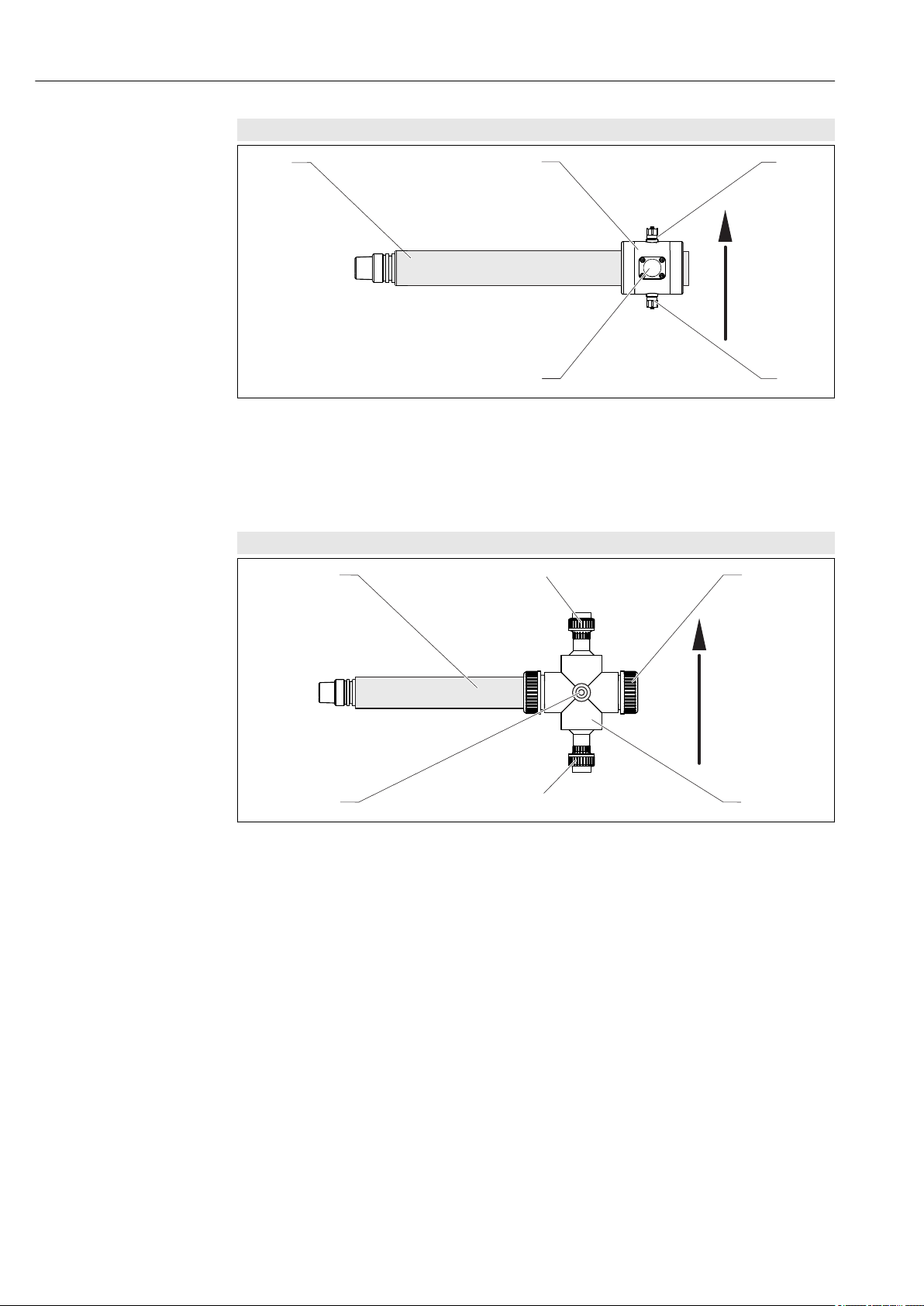
Flow assembly CAS51D 2-40 mm for small sample volumes
A0013266
8 Horizontally, in flow assembly, arrow points in the direction of flow
1 Sensor
2 Flow assembly
3 Medium outlet
4 Medium inflow
5 Window, required for aligning the sensor
Flowfit CYA251 flow assembly
9 Horizontally, in flow assembly CYA251, arrow points in the direction of flow
1 Sensor
2 Medium outlet
3 Cap
4 Flow assembly
5 Medium inflow
6 Rinse connection
A0032901
5.2 Mounting the sensor
5.2.1 Installation instructions
14 Endress+Hauser
To ensure correct measurement, the windows in the cuvette must be free from any
sedimentation. The best way to ensure this is through the use of a cleaning unit
(accessory) operated by compressed air.
For horizontal orientations:
‣
Mount the sensor in such a way that air bubbles can escape from the cuvette slot (do
not point it downwards).
Page 15

Viomax CAS51D Mounting
1
2
3
4
1
2
3
4
5
5.3 Immersion operation
5.3.1 Fixed installation with wastewater assembly
10 Installation secured on railing
1 Wastewater assembly Flexdip CYA112
2 Flexdip CYH112 holder
3 Rail
4 Viomax CAS51D
A0013347
11 Installation with upright post
1 Protective cover
2 Liquiline CM44x multi-channel transmitter
3 Wastewater assembly Flexdip CYA112
4 Viomax CAS51D
5 Flexdip CYH112 holder
A0013215
This type of installation is particularly suitable for strong or turbulent medium flow
(>0.5 m/s (1.6 ft/s)) in basins or channels. A cleaning unit (accessory) operated by
compressed air significantly extends the maintenance intervals for the sensor.
Endress+Hauser 15
Page 16

Mounting Viomax CAS51D
2
3
2
3
4
5.3.2 Installation with chain retainer
12 Chain retainer on railing
1 Wastewater assembly Flexdip CYA112
2 Flexdip CYH112 holder
3 Rail
4 Viomax CAS51D
A0013348
13 Chain retainer on upright post
1 Protective cover
2 Liquiline CM44x multi-channel transmitter
3 Wastewater assembly Flexdip CYA112
4 Viomax CAS51D
5 Flexdip CYH112 holder
A0013351
The chain retainer is particularly suitable for applications that require a sufficient distance
between the mounting location and the edge of the aeration basin. As the assembly is
freely suspended, any vibration of the upright post is practically ruled out.
The swinging movement of the chain retainer enhances the self-cleaning effect of the
optics. A cleaning unit (accessory) operated by compressed air significantly extends the
maintenance intervals for the sensor.
16 Endress+Hauser
Page 17

Viomax CAS51D Mounting
2
3
4
Ø 6.5 (0.26)
86
(3.39)
30 (1.18)
100 (3.94)
70 (2.76)
**
70 (2.76)
60 (2.36)
5.4 Flow operation
5.4.1 Flow assembly for clear water and small sample volumes
A0013352
14 Sensor with flow assembly
1 Transmitter
2 Viomax CAS51D
3 Flow assembly
4 Sensor holder
Securing the holder
15 Dimensions in mm (inch)
** Variable length
1. For the necessary installation dimensions, refer to the drawing. Mount the sensor in
a horizontal position (as shown in the drawing).
Drill holes for the mounting clamps into a wall or panel.
2. Secure the mounting clamps. The required fastening fixtures (screws, wall plugs) are
not included in the scope of delivery of the kit and must be provided by the customer.
3.
A0013290
Endress+Hauser 17
Release the hexagonal nuts of the mounting clamps and remove the top half.
Page 18

Mounting Viomax CAS51D
M5
4.
Position the sensor in the mounting clamps and screw on the top parts, tightening by
hand (it should still be possible to move the sensor).
Mount the flow assembly
A0033056
16 Sensor installed in flow assembly
1.
Release the threaded rings of the flow assembly and remove the two O-rings.
2. Check if the silicone grease provided with the kit is permitted for use in your
application. If not, use a grease that is suitable for your application
Grease the O-rings.
3.
First slide a threaded ring (thread in the direction of the assembly) onto the sensor,
followed by an O-ring.
4.
Now slide the assembly onto the sensor, followed by the second O-ring and the
second threaded ring.
18 Endress+Hauser
Page 19

Viomax CAS51D Mounting
5.
Open the cap on the viewing window.
6.
Position the assembly on the sensor in such a way that the cuvette gap is visible in
the center of the window.
7.
Tighten the two threaded rings. Ensure that you do not change the position of the
assembly.
8.
The cuvette gap must still be visible in the center of the viewing window:
Close the viewing window again with the cap.
To guard against loss:
Secure the viewing window to one of the hose connections (no diagram) using
the transparent cord.
Endress+Hauser 19
Page 20

Mounting Viomax CAS51D
1
3
56
2
7
2
2 4
2
Connection diagram
A0013361
1 Main pipe 5 Flow assembly
2 Manually actuated or solenoid valves 6 Medium inflow
3 Medium outlet 7 Medium sampling
4 Medium return
Connect the medium inflow and outlet to the assembly's hose connections as shown in
‣
the diagram.
This fills the assembly from below and ensures that the assembly is self-venting.
There must be a minimum flow rate of 100 ml/h (0.026 gal/h). Increased response times
must be taken into account.
As an alternative to bypass operation, you can also direct the sample flow from a filter unit
with an open outlet through the assembly:
A0013434
17 Flow assembly with open outlet
1 Pump
2 Open outlet
3 Filter unit
20 Endress+Hauser
Page 21

Viomax CAS51D Mounting
3
4
6
5
2
1
3
56
2
7
2
2 4
5.4.2 Flow assembly Flowfit CYA251
A0032917
18 Measuring system with CYA251
1 Transmitter
2 Flow assembly
3 Medium outlet
4 Cap
5 Medium inflow
6 Viomax CAS51D
A0032920
19 Connection diagram
1 Main pipe 5 Medium inflow
2 Manually actuated or solenoid valves 6 Flow assembly
3 Medium outlet 7 Medium removal
4 Medium return
Mount the sensor in the assembly in accordance with its Operating Instructions
(BA00495C).
There must be a minimum flow rate of 100 ml/h (0.026 gal/h). Increased response
times must be taken into account.
Endress+Hauser 21
Page 22

Mounting Viomax CAS51D
2
As an alternative to bypass operation, you can also direct the sample flow from a filter unit
with an open outlet through the assembly:
20 Flow assembly with open outlet
1 Pump
2 Open outlet
3 Filter unit
5.5 Mounting the cleaning unit
Sensors with gap width of 2 mm or 8 mm
Mount the compressed air cleaning unit prior to installing the sensor in the measuring
point, or remove the sensor from the medium. Clean the sensor if necessary.
1.
Screw the elbow plug from the accessory kit into the mounting hole behind the
sensor gap, and tighten by hand as far as it will go.
2.
A0032921
Connect the compressed air supply at the installation location. Use the hose piece
with hose coupling provided with the sensor if desired.
22 Endress+Hauser
Page 23

Viomax CAS51D Mounting
SAC sensors with a gap width of 40 mm
Mount the compressed air cleaning unit prior to installing the sensor in the measuring
point, or remove the sensor from the medium. Clean the sensor if necessary.
1.
Screw the air diffuser from the accessory kit into the mounting holes behind the
sensor gap, and tighten by hand as far as it will go.
2.
Connect the compressed air supply at the installation location. Use the hose piece
with hose coupling provided with the sensor if desired.
5.6 Post-installation check
Put the sensor into operation only if you can answer "yes" to the following questions:
• Are the sensor and cable undamaged?
• Is the orientation correct?
• Is the sensor installed in an assembly and not freely suspended from the cable?
• Is the cable routed so that it is completely dry (routed inside an assembly if necessary)?
Endress+Hauser 23
Page 24

Electrical connection Viomax CAS51D
1
2
3
4
6 Electrical connection
WARNING
L
Device is live!
Incorrect connection may result in injury or death!
The electrical connection may be performed only by an electrical technician.
‣
The electrical technician must have read and understood these Operating Instructions
‣
and must follow the instructions contained therein.
Prior to commencing connection work, ensure that no voltage is present on any cable.
‣
6.1 Connecting to the transmitter
6.1.1 Connecting the cable shield to the grounding rail of the transmitter
WARNING
L
Sensor not grounded
If maintenance work (lamp replacement) is not performed correctly, moisture or dirt may
penetrate the housing and cause an electric shock to anyone who touches it.
To guarantee safety in the workplace, always connect the sensor's cable shield to the
‣
grounding rail of the transmitter or control cabinet.
If possible, only use terminated original cables. The sensor cables must be shielded.
Cable sample (does not necessarily correspond to the original cable supplied)
21 Terminated cable
1 Outer shield (exposed)
2 Cable cores with ferrules
3 Cable sheath (insulation)
1) Please note the instructions in the "Ensuring the degree of protection" section.
22 Inserting the cable
4 Grounding clip
23 Tighten screw (2 Nm)
The cable shield is grounded using
the grounding clamp.
1)
1. Release a suitable cable gland on the bottom of the housing and remove the dummy
plug.
2. Making sure the gland is facing the right direction, thread the gland onto the cable
end and pull the cable through the entry and into the housing.
3. Route the cable in the housing in such a way that the exposed cable shield fits into
one of the cable clamps and the cable cores can be easily routed as far as the
connection plug on the electronics module.
4. Open the cable clamp and clamp the cable in place. Then tighten the screw of the
cable clamp again.
5. Connect cable cores as per the wiring diagram.
24 Endress+Hauser
Page 25

Viomax CAS51D Electrical connection
85 86
85
2DS
1
2
86
97 88 8798
97 88 8798
Sensor 1
Sensor 2
PK
GY
GN
YE
Sensor
85 86
85
1
2
86
97 88 8798
Sensor 1
PK
GY
GN
YE
BN
WH
Sensor
6. Tighten the cable gland from outside.
6.1.2 Connecting the sensor
The following connection options are available:
• via M12 connector (version: fixed cable, M12 connector)
• via sensor cable to the plug-in terminals of a sensor input on the transmitter (version:
fixed cable, end sleeves)
A0033092
24 Sensor connection to sensor input (left) or via M12 connector (right)
The maximum cable length is 100 m (328.1 ft).
6.2 Ensuring the degree of protection
Only the mechanical and electrical connections which are described in these instructions
and which are necessary for the required, designated use, may be carried out on the device
delivered.
Exercise care when carrying out the work.
‣
Otherwise, the individual types of protection (Ingress Protection (IP), electrical safety, EMC
interference immunity) agreed for this product can no longer be guaranteed due,
for example to covers being left off or cable (ends) that are loose or insufficiently secured.
6.3 Post-connection check
Put the sensor into operation only if you can answer yes to all of the following
‣
questions.
Device condition and specifications Notes
Is the outside of the sensor, assembly and cable undamaged? Visual inspection
Electrical connection Notes
Has cable shield been applied to grounding rail of transmitter? Cable shield is absolutely
Are the installed cables strain-relieved and not twisted?
essential
Endress+Hauser 25
Page 26

Operation Viomax CAS51D
Device condition and specifications Notes
Is a sufficient length of the cable cores stripped, and is it positioned in the
terminal correctly?
Are all the screws terminals properly tightened? Tighten
Check the fit (by pulling
gently)
7 Operation
Verify that a representative measured value is displayed on the transmitter.
‣
For solids that have a tendency to form deposits, ensure that the medium is mixed
‣
sufficiently.
7.1 Calibration
Calibration is performed in the process by comparing the values to an external standard
method, by calibrating with standard solutions or by using a combination of both (addition
of standard).
7.1.1 Factory calibration
Nitrate sensor
The sensor is precalibrated on leaving the factory.
As such, it can be used in a wide range of clear water measurements without the need for
additional calibration.
SAC sensor
The sensor is precalibrated on leaving the factory (calibrated with KHP).
Calibration to the customer process is nevertheless advantageous in the majority of cases.
Reason: Organic compounds other than KHP react differently in the spectrum.
The factory calibration is based on 20 calibration points and is adjusted at three points
during production. The factory calibration cannot be deleted and can be retrieved at any
time. Single-point and two-point calibrations - performed as customer calibrations - are
referenced to this factory calibration.
7.1.2 Types of calibration
In addition to the factory calibrations, which cannot be changed, the sensor contains six
additional data records for storing process calibrations or for adaptation to the relevant
measuring point (application). Each calibration data record can have up to five calibration
points.
The sensor offers a wide range of options for adapting the measurement to the application
in question:
• Calibration or adjustment (1 to 5 points)
• Entry of a factor (multiplication of measured values by a constant factor)
• Entry of an offset (addition/subtraction of a constant factor to/from the measured
values)
• Duplication of factory calibration data records
One-point or multiple point calibration
You do not have to remove the sensor from the medium for calibration. You can calibrate it
directly in the application.
1. For the calibration, ensure that the measuring gap is not soiled with deposit buildup:
Clean the measuring gap of the sensor (remove soiling and deposits).
26 Endress+Hauser
Page 27

Viomax CAS51D Operation
1 2 3 4 5 6 7 8 9
1
2
3
4
5
6
7
8
9
x
y
2. To perform the calibration, immerse the sensor in the medium in such a way that the
measuring gap is completely filled with the medium.
All air bubbles and air pockets must be cleaned out of the measuring gap during
immersion.
• In the calibration table, the actual values can be edited as well as the set points
(right and left columns).
• Additional pairs of calibration values (actual values and set points) can be added, if
required, even without measurement in a medium.
Lines interpolate between the calibration points.
Give your calibration data records meaningful and useful names.
‣
For example, the name could contain the name of the application on which your data
record was originally based. This makes it easier for you to distinguish between different
data records.
Principle of a 1-point calibration
The measured error between the measured value of the sensor and the laboratory
measured value is too large. This is corrected by a 1-point calibration.
25 Principle of a 1-point calibration
x Measured value
y Target sample value
Blue Factory calibration
Red Application calibration
A0039320
1. Select data record.
2. Set the calibration point in the medium and enter the target sample value (laboratory
value).
Endress+Hauser 27
Page 28

Operation Viomax CAS51D
1 2 3 4 5 6 7 8 9
1
2
3
4
5
6
7
8
9
x
y
Principle of a 2-point calibration
Measured value deviations are to be compensated for at 2 different points in an
application (e.g. the maximum and minimum value of the application). This aims to ensure
a maximum level of accuracy between these two extreme values.
A0039325
26 Principle of a 2-point calibration
x Measured value
y Target sample value
Blue Factory calibration
Red Application calibration
1. Select a data record.
2. Set 2 different calibration points in the medium and enter the corresponding set
points.
A linear extrapolation is performed outside the calibrated operational range (gray
line).
The calibration curve must be monotonically increasing.
28 Endress+Hauser
Page 29

Viomax CAS51D Operation
1 2 3 4 5 6 7 8 9
1
2
3
4
5
6
7
8
9
x
y
Principle of multiple point calibration
A0039322
27 Principle of multipoint calibration (3 points)
x Measured value
y Target sample value
Blue Factory calibration
Red Application calibration
1. Select data record.
2. Set 3 different calibration points in the medium and specify the corresponding set
points.
A linear extrapolation is performed outside the calibrated operational range (gray
line).
The calibration curve must be monotonically increasing.
Endress+Hauser 29
Page 30

Operation Viomax CAS51D
1 2 3 4 5 6 7 8 9
1
2
3
4
5
6
7
8
9
x
y
f = 1.1
Principle of entering a factor
With the "Factor" function, the measured values are multiplied by a constant factor. The
functionality corresponds to that of a 1-point calibration.
Example:
This type of adjustment can be selected if the measured values are compared to the
laboratory values over a longer period of time and all values are too low by a constant
factor, e.g. 10%, in relation to the laboratory value (target sample value).
In the example, the adjustment is made by entering the factor 1.1.
A0039329
28 Principle of factor calibration
x Measured value
y Target sample value
Blue Factory calibration
Red Factor calibration
30 Endress+Hauser
Page 31

Viomax CAS51D Operation
1 2 3 4 5 6 7 8 9
1
2
3
4
5
6
7
8
9
x
y
Principle of entering an offset
With the "Offset" function, the measured values are offset by a constant amount (added or
subtracted).
A0039330
29 Principle of an offset
x Measured value
y Target sample value
Blue Factory calibration
Red Offset calibration
7.1.3 Stability criterion
During the calibration process, the measured values are checked to ensure that they
remain constant.
You use the stability criterion to define maximum deviations during a calibration. Only a
measured value within the specified deviation is accepted.
The stability criterion includes:
• The maximum permitted deviation in temperature measurement
• The maximum permitted deviation in measured value as a %
• the minimum time frame in which these values must be maintained
If the measured value or temperature deviate more than is permitted in the specified time
frame, this calibration point becomes invalid and a warning is issued.
Endress+Hauser 31
Page 32

Operation Viomax CAS51D
The stability criteria are used to monitor the quality of the individual calibration points in
the course of the calibration process. The aim is to achieve the best possible calibration
quality in the shortest possible time frame while taking external conditions into account.
• For high-precision calibrations in the laboratory, the maximum deviation permitted in
the measured value can be kept as small as possible and the time frame selected can be
as long as possible..
• For calibrations in the field in adverse weather and environmental conditions, the
maximum deviation permitted in the measured value can be kept suitably large and the
time frame selected can be kept suitably short.
Operating Instructions Memosens inputs BA01245C
7.1.4 Determining the reference values in the laboratory
Nitrate sensor
1. Take a representative sample of the medium.
2. Take suitable measures to ensure that the process of nitrate reduction in the sample
does not progress any further, such as immediate filtration (0.45 µm) of the sample
as per DIN 38402.
3. Determine the concentration of nitrate in the sample using the laboratory method
(for example, by colorimetric means using a cuvette test ‐ the standard method as per
DIN 38405 Part 9).
SAC sensor
1. Take a representative sample of the medium.
2. Take suitable measures to ensure that the process of biological and chemical
reduction in the sample does not progress any further.
3. Determine the measured values of your sample array using the laboratory method
(for example, by colorimetric means using a cuvette test).
7.1.5 Nitrate sensor
Processes with nitrate values > 0.1 mg/l
1. Take sample and determine nitrate concentration in the laboratory.
2. Calibrate and adjust the sensor using the laboratory value.
Processes with very different nitrate values
1. At time A, take a sample with a high concentration, and measure and calibrate the
sample.
2. At time B - which can be a few days later - take a sample with a low concentration,
and measure and calibrate the second value.
Calibration with the addition of standard
If the sludge parameters tend to be constant, you can perform the calibration with a
sample with a low concentration of nitrate and then add standard to the sample.
1. Take a larger sample (bucket) and analyze some of it by colorimetric means.
2. Calibrate the value of the calorimetric measurement in the sensor.
3. Add standard to the sample and determine the laboratory value.
4. Calibrate the laboratory value of the sample with added standard in the sensor.
32 Endress+Hauser
Page 33

Viomax CAS51D Operation
Avoid incorrect measurements.
Drinking water may contain higher concentrations of nitrate and is not suitable as a
‣
blank value. Use fully deionized water as a blank value.
During calibration, make sure the sample is homogeneous.
‣
When calibrating, start with a low concentration and increase the concentrations
‣
gradually to prevent nitrate carryover.
Clean and dry the sensor after a calibration. Ensure that there is no medium residue in
‣
the cuvette gap. In this way, you avoid mixing the different samples and changing the
nitrate concentrations.
7.1.6 SAC sensor
The required data record is activated by selecting the application in question and can be
adapted to that application using the following options:
• Calibration (1 to 10 points)
• Entry of a factor (multiplication of measured values by a constant factor)
• Entry of an offset (addition/subtraction of a constant factor to/from the measured
values)
• Duplication of factory calibration data records
• Adjustment of the conversion factors
Further data records can be created in the sensor and adapted to the application by
means of calibration or by entering a factor or offset. Two free, unused data records
are available for this. The number of free data records can be increased if necessary by
deleting (sample) data records that are not required. The sample data records are
restored to factory status when the sensor is reset.
General calibration steps
1. Take a sample.
2. Determine the SAC value of the sample in the laboratory.
3. Calibrate and adjust the sensor using the laboratory value.
In the SAC sensor version, the calculated variables COD, TOC, BOD and DOC can also be
output if desired, in addition to the actual measured variable. These variables are based on
the following ratios:
1 mg/l KHP = ~1.176 mg/l COD
1 mg/l KHP = ~0.4705 mg/l TOC
1 mg/l KHP = ~1.176 mg/l BOD
1 mg/l KHP = ~0.4705 mg/l DOC
Using other conversion factors
Sometimes the conversion factors for COD, TOC, BOD or DOC are predetermined by control
bodies. In such instances, these factors can be adjusted as follows:
1. Copy the factory data record to a free data record of your choice in the SAC basic
setting.
A copy is necessary because the factory data record cannot be modified. If you already have
another data record, you can change its factors directly.
2. Activate the new data record. (In the Setupmenu)
3. Set the desired factor. (In the CALmenu)
4. Set the device to the desired measured variable. (In the Setupmenu)
Operating Instructions Memosens inputs BA01245C.
The SAC sensor can be calibrated for the measured variables SAC, COD, TOC, BOD and
DOC.
Endress+Hauser 33
Page 34

Operation Viomax CAS51D
If the sensor has been calibrated for the measured variable SAC, the conversion factors for
COD, TOC, BOD or DOC can be adjusted at a later stage. If calibrated for TOC, COD, BOD or
DOC, only the factor for the measured variable in use can be changed subsequently.
Avoid incorrect measurements.
Drinking water contains many organic elements. The use of fully deionized water as a
‣
blank is also recommended here.
During calibration, make sure the medium is homogeneous.
‣
Avoid any carryover of organic elements during calibration.
‣
Processes with widely varying SAC values
Record calibration points for different operating statuses. Example of a WWTP inlet:
• After a rainy spell
• In "normal conditions"
• After a dry spell
1. Save the points in a data record of your choice and add the associated laboratory
results.
2. Activate the calibration once you have set a sufficient number of points.
While this type of calibration can be more time-consuming, it allows the precise
adjustment of the measurement technology to the operating conditions of the plant.
7.1.7 Calibrating and adjusting the sensor
To calibrate the sensor, use the same medium sample or sample array that you used to
determine the laboratory measured values. The sample array can also be pure standard
solutions.
The general sequence of a calibration is as follows:
1. Select data record.
2. Place sensor in medium.
3. During calibration, ensure that the medium is well homogenized.
4. Start the calibration for the measuring point.
5. If you wish to calibrate just one point:
End the calibration by accepting the calibration data.
Otherwise continue with the next step.
6. Add parent solution to the sample for the second measuring point and determine its
measured value. The reference value is calculated from the laboratory measured
value plus the added concentration.
7. Repeat the previous step as often as needed until you have reached the desired
number of calibration points (max. 5).
To avoid incorrect calibration from carryover:
• Always go from a low concentration to a high concentration.
• Clean and dry the sensor after each measurement.
• Make sure to remove medium residue in the sensor gap and in the connection opening
for the compressed air (e.g. by rinsing with the next calibration solution).
34 Endress+Hauser
Page 35

Viomax CAS51D Diagnostics and troubleshooting
7.2 Cyclic cleaning
Compressed air is most suitable for automatic cyclic cleaning. There is a connection for
compressed air on every sensor. The cleaning unit, which is supplied with the device or can
be retrofitted, operates effectively at a rate of 20 l/min (5.4 US gal/min).
Type of soiling Cleaning interval Cleaning duration
Severe fouling with rapid buildup 5 min 10 s
Low risk of soiling 10 min 10 s
8 Diagnostics and troubleshooting
When troubleshooting, the entire measuring point must be taken into account:
• Transmitter
• Electrical connections and cables
• Assembly
• Sensor
The possible causes of error in the following table relate primarily to the sensor.
Problem Testing Solution
No display, no sensor
reaction
Display value too high
or too low
Display value
fluctuating greatly
• Power supplied to transmitter?
• Sensor connected correctly?
• Medium flow present?
• Buildup on optical windows?
• Buildup on optical windows?
• Gas bubbles present?
• Sensor calibrated?
Gas bubbles present? 1. Eliminate gas bubbles
1. Connect mains voltage
2. Connect sensor correctly
3. Ensure medium is flowing
4. Clean sensor
1. Cleaning
2. Eliminate gas bubbles
3. Calibration
4. Check data record and modify if necessary
5. Examine in workshop with test unit
2. Check mounting location and select a
different mounting location if necessary.
Please observe the troubleshooting instructions provided in the Operating Instructions
of the transmitter. Check the transmitter if necessary.
Endress+Hauser 35
Page 36

Maintenance Viomax CAS51D
9 Maintenance
You must perform maintenance tasks at regular intervals.
‣
We recommend setting the maintenance times in advance in an operations journal or log.
The maintenance cycle primarily depends on the following:
• The system
• The installation conditions
• The medium in which measurement takes place
CAUTION
L
Acid or medium
Risk of injury, damage to clothing and the system!
Wear protective goggles and safety gloves.
‣
Clean away splashes on clothes and other objects.
‣
9.1 Maintenance intervals
The sensor requires very little maintenance, particularly if a cleaning unit is connected.
Nevertheless, maintenance must be performed at regular intervals. Schedule maintenance
times in advance in an operations journal or log.
Monthly: Visual check, clean sensor if necessary.
Cleaning intervals depend on the medium.
Every 125 million flashes (= two years at 2 Hz) or at least
every four years:
Every 250 million flashes (= four years at 2 Hz) or at least
every eight years:
Replace optical filters (manufacturer service team)
Replace strobe lamp (manufacturer service team)
9.2 Cleaning the sensor
Sensor fouling can affect the measurement results and even cause a malfunction.
The sensor must be cleaned regularly to ensure reliable measurement results. The
frequency and intensity of the cleaning process depend on the medium.
Clean the sensor:
• As specified in the maintenance schedule
• Before every calibration
• Before returning it for repairs
Type of fouling Cleaning measure
Lime deposits
Dirt particles on the optics
Deposit buildup on the optics There may be deposit buildup in the non-visible range (UV). Therefore, always
After cleaning:
Rinse the sensor thoroughly with water.
‣
Immerse the sensor in 1 to 5% hydrochloric acid (for several minutes).
‣
Clean the optics with a cleaning cloth.
‣
clean the optics.
Wet a cotton bud with 5-10% phosphoric acid or 5-10% hydrochloric acid
‣
and use it to clean the optics.
36 Endress+Hauser
Page 37

Viomax CAS51D Repairs
9.3 Maintenance of optical filters and strobe lamp
This work must be performed only by the manufacturer service team. Contact your Sales
Center.→ 37
Replacing the optical filter and strobe lamp also entails recalibrating and readjusting
the sensor in the factory.
10 Repairs
10.1 Return
The product must be returned if repairs or a factory calibration are required, or if the
wrong product was ordered or delivered. As an ISO-certified company and also due to legal
regulations, Endress+Hauser is obliged to follow certain procedures when handling any
returned products that have been in contact with medium.
To ensure the swift, safe and professional return of the device:
Refer to the website www.endress.com/support/return-material for information on the
‣
procedure and conditions for returning devices.
10.2 Disposal
The device contains electronic components. The product must be disposed of as electronic
waste.
Observe the local regulations.
‣
Endress+Hauser 37
Page 38

Accessories Viomax CAS51D
11 Accessories
11.1 Assemblies
Flexdip CYA112
• Immersion assembly for water and wastewater
• Modular assembly system for sensors in open basins, channels and tanks
• Material: PVC or stainless steel
• Product Configurator on the product page: www.endress.com/cya112
Technical Information TI00432C
Flowfit CYA251
• Connection: See product structure
• Material: PVC-U
• Product Configurator on the product page: www.endress.com/cya251
Technical Information TI00495C
Flow assembly for CAS51D
• For small flow volumes
• Connection: hose, OD 6 mm
• Material: PVC-U
• Two brackets for CAS51D
• Order number: 71110000
11.2 Holder
Flexdip CYH112
• Modular holder system for sensors and assemblies in open basins, channels and tanks
• For Flexdip CYA112 water and wastewater assemblies
• Can be affixed anywhere: on the ground, on the capstone, on the wall or directly onto
railings.
• Plastic or stainless steel version
• Product Configurator on the product page: www.endress.com/cyh112
Technical Information TI00430C
11.3 Compressed air cleaning
Compressed air cleaning for CAS51D
• Connection: 6 or 8 mm (metric) or 6.35 mm (¼")
• Order numbers for sensor with 2 mm gap or 8 mm gap:
• 6 mm (with 300 mm hose and 8 mm adapter)
Order No.: 71110787
• 6.35 mm (¼")
Order No.: 71110788
• Order numbers for sensor with 40 mm gap:
• 6 mm (with 300 mm hose and 8 mm adapter)
Order No.: 71126757
• 6.35 mm (¼")
Order No.: 71126758
38 Endress+Hauser
Page 39

Viomax CAS51D Accessories
1
2
4
A
B
A0013263
30 Compressed air cleaning for CAS51D
A Cleaning for sensors with 2 mm and 8 mm gap
B Cleaning for sensors with 40 mm gap
1 Adapter, 8 mm
2 300 mm hose (Ø = 6 mm)
3 Coupling, 6 mm or 6.35 mm (¼") for 2 mm and 8 mm gap
4 Coupling, 6 mm or 6.35 mm (¼") for 40 mm gap
Compressor
• For compressed air cleaning
• 230 V AC order no. 71072583
• 115 V AC order no. 71194623
11.4 Standard solutions
Nitrate standard solutions, 1 liter
• 5 mg/l NO3-N, order number: CAY342-V10C05AAE
• 10 mg/l NO3-N, order number: CAY342-V10C10AAE
• 15 mg/l NO3-N, order number: CAY342-V10C15AAE
• 20 mg/l NO3-N, order number: CAY342-V20C10AAE
• 30 mg/l NO3-N, order number: CAY342-V20C30AAE
• 40 mg/l NO3-N, order number: CAY342-V20C40AAE
• 50 mg/l NO3-N, order number: CAY342-V20C50AAE
KHP standard solution
CAY451‐V10C01AAE, 1000 ml parent solution 5 000 mg/l TOC
Endress+Hauser 39
Page 40

Technical data Viomax CAS51D
12 Technical data
12.1 Input
Measured variables Nitrate
NO3-N [mg/l], NO3 [mg/l]
SAC
SAC [1/m], COD [mg/l], TOC [mg/l], BOD [mg/l], DOC [mg/l], transmission [%]
Measuring ranges
CAS51D-**A2 (2 mm gap) 0.1 to 50 mg/l NO3-N
0.4 to 200 mg/l NO
Clear water and sludge activation
CAS51D-**A1 (8 mm gap) 0.01 to 20 mg/l NO3-N
0.04 to 80 mg/l NO
Clear water (with a COD (KHP) content of up to 125 mg/l and up
to 50 FNU turbidity based on mineral kaolin)
CAS51D-**C1 (40 mm gap) SAC 0 to 50 1/m
CSB/BSB 0 to 75 mg/l
TOC/DOC 0 to 30 mg/l
Clear water, low measuring range, drinking water
CAS51D-**C2 (8 mm gap) SAC 0 to 250 1/m
COD/BOD 0 to 375 mg/l
TOC/DOC 0 to 150 mg/l
Clear water, medium measuring range, drinking water,
wastewater treatment plant outlet, monitoring of bodies of
water
CAS51D-**C3 (2 mm gap) SAC 0 to 1000 1/m
COD/BOD 0 to 1500 mg/l
TOC/DOC 0 to 600 mg/l
Organic load in the inlet, influent control, industrial processes
1) equivalent KHP
3
3
1)
1)
1)
1)
1)
1)
The possible measuring range depends greatly on the properties of the medium.
Empirical values for typical COD measuring ranges
Inlet of municipal wastewater treatment
plant
Influent from milk-processing industry 0 to 10 000 mg/l COD
Influent from chemical industry 0 to 10 000 mg/l COD
0 to 4000 mg/l COD
40 Endress+Hauser
Page 41

Viomax CAS51D Technical data
12.2 Performance characteristics
Reference operating
20 °C (68 °F), 1013 hPa (15 psi)
conditions
Measured error
Repeatability
6)
6)
Nitrate With 0.1 to 50 mg/l NO3-N (2 mm cuvette gap):
SAC 2 % of full scale value for standard measurement with potassium
Nitrate
At least ±0.2 mg/l NO3-N
SAC
0.5 % of end of measuring range (for homogeneous media)
Detection limits Nitrate
• CAS51D-AAA1
0.003 mg/l NO3-N
• CAS51D-AAA2
0.013 mg/l NO3-N
SAC
In relation to the standard potassium hydrogen phthalate (KHP):
• CAS51D-AAC1
0.045 mg/l COD
• CAS51D-AAC2
0.3 mg/l COD
• CAS51D-AAC3
1.5 mg/l COD
2 % of full scale value above 10 mg/l
0.4 % of full scale value below 10 mg/l
With 0.01 to 20 mg/l NO3-N (8 mm cuvette gap):
2 % of full scale value above 2 mg/l
0.2 % below 2 mg/l
hydrogen phthalate (KHP)
Determination limits Nitrate
• CAS51D-AAA1
0.01 mg/l NO3-N
• CAS51D-AAA2
0.043 mg/l NO3-N
SAC
In relation to the standard potassium hydrogen phthalate (KHP):
• CAS51D-AAC1
0.15 mg/l COD
• CAS51D-AAC2
1.0 mg/l COD
• CAS51D-AAC3
5.0 mg/l COD
Long-term drift Nitrate
Better than 0.1 mg/l NO3-N over one week
6) The measured error contains all the uncertainties of the sensor and transmitter (electrode system). It does not contain all the uncertainties
caused by the reference material and adjustments that may have been performed.
Endress+Hauser 41
Page 42

Technical data Viomax CAS51D
SAC
Better than 0.2 % of end of measuring range over one week
12.3 Environment
Ambient temperature range
Storage temperature –20 to 70 °C (–4 to 158 °F)
Degree of protection IP 68 (1 m (3.3 ft) water column, 60 days, 1 mol/l KCl)
–20 to 60 °C (–4 to 140 °F)
12.4 Process
Process temperature 5 to 50 °C (41 to 122 °F)
Process pressure (absolute) 0.5 to 10 bar (7.3 to 145 psi) (abs.)
Minimum flow No minimum flow required.
For solids which have a tendency to form deposits, ensure that sufficient mixing is
performed.
12.5 Mechanical construction
Dimensions → 6
Weight Approx. 1.6 kg (3.53 lbs) (without cable)
Materials Sensor Stainless steel 1.4404 (AISI 316 L)
Optical windows Sapphire
O-rings EPDM
Process connections G1 and NPT ¾''
42 Endress+Hauser
Page 43

Viomax CAS51D Index
Index
A
Accessories ................................ 38
Ambient temperature range ................... 42
Approvals ................................. 12
C
Cable shield ............................... 24
Calibration
Factory calibration ........................ 26
Certificates ................................ 12
Check
Connection ..............................25
Mounting ...............................23
Cleaning ............................... 35, 36
Cleaning unit .............................. 22
Cross-interference
Nitrate ..................................9
SAC ................................... 10
Cyclic cleaning ..............................35
D
Degree of protection ......................... 42
Designated use .............................. 4
Detection limits .............................41
Determination limits ......................... 41
Device description ............................ 6
Diagnostics ................................ 35
Dimensions .................................6
Disposal .................................. 37
E
Electrical connection ......................... 24
Ensuring the degree of protection ............... 25
F
Factor ....................................30
Factory calibration ...........................26
Flow operation ............................. 17
I
Immersion operation ......................... 15
Incoming acceptance ......................... 11
Input .....................................40
Installation instructions .......................14
Interpreting the order code .................... 11
L
Long-term drift ............................. 41
Measuring ranges ........................... 40
Mechanical construction ...................... 42
Minimum flow ............................. 42
Mounting ................................. 13
Mounting location ...........................13
Multiple point calibration ..................... 29
N
Nameplate ................................ 11
Nitrate .................................... 9
O
Offset .................................... 31
One-point calibration ........................ 27
Operating principle ........................... 8
Operation ................................. 26
Optical filters .............................. 37
Orientation ................................ 13
P
Performance characteristics ....................41
Post-connection check ........................25
Post-installation check ....................... 23
Process connections ..........................42
Process pressure (absolute) .................... 42
Process temperature ......................... 42
Product identification ........................ 11
Product page ...............................11
R
Reference operating conditions ................. 41
Repairs ................................... 37
Repeatability ...............................41
Return ................................... 37
S
SAC ...................................... 9
Safety instructions ............................4
Scope of delivery ............................ 12
Sensor ................................... 14
Cleaning ............................... 36
Connecting ..............................25
Design .................................. 6
Dimensions .............................. 6
Stability criterion ............................31
Storage temperature ......................... 42
Strobe lamp ............................... 37
Symbols ................................... 3
M
Maintenance ...............................36
Maintenance intervals ........................36
Manufacturer's address ....................... 12
Materials ................................. 42
Maximum measured error ..................... 41
Measured variables .......................... 40
Measuring principle ...........................8
Endress+Hauser 43
T
Technical data ..............................40
Troubleshooting ............................ 35
Two-point calibration ........................ 28
U
Use .......................................4
Page 44

Index Viomax CAS51D
W
Warnings .................................. 3
Weight ................................... 42
Wiring ................................... 24
44 Endress+Hauser
Page 45

Page 46

Page 47

Page 48

*71447513*
71447513
www.addresses.endress.com
 Loading...