

Page 1
TI01380D/06/EN/01.18
71409639
2018-08-01
Products Solutions Services
Technical Information
Proline Promass A 200
Coriolis flowmeter
Flowmeter with genuine two-wire technology for accurate measurement of
smallest flow quantities
Application
• Measuring principle operates independently of physical
fluid properties such as viscosity or density
• Suitable for applications with the smallest flow quantities in
the chemical industry
Device properties
• Nominal diameter: DN 1 to 4 (¹⁄₂₄ to ¹⁄₈")
• Process pressure: up to 430.9 bar (6 250 psi)
• Medium temperature up to +205 °C (+401 °F)
• Loop-powered technology
• Robust dual‐compartment housing
• Plant safety: worldwide approvals (SIL, Haz. area)
Your benefits
• Space-saving installation – compact, lightweight sensor
• Highest product quality – self-drainable measuring tube
design available in all line sizes
• Optimum process safety – resistant to corrosive ambient
conditions and internal clogging
• Convenient device wiring – separate connection
compartment
• Safe operation – no need to open the device due to display
with touch control, background lighting
• Integrated verification – Heartbeat Technology
Page 2

Table of contents
Proline Promass A 200
About this document ........................ 4
Symbols used ................................ 4
Function and system design ................... 5
Measuring principle ............................ 5
Measuring system ............................. 7
Safety ..................................... 7
Input ..................................... 9
Measured variable ............................. 9
Measuring range .............................. 9
Operable flow range ........................... 10
Input signal ................................ 10
Output .................................. 10
Output signal ............................... 10
Signal on alarm .............................. 12
Load ..................................... 13
Ex connection data ........................... 14
Low flow cut off ............................. 17
Galvanic isolation ............................ 18
Protocol-specific data .......................... 18
Power supply ............................. 19
Terminal assignment .......................... 19
Pin assignment, device plug ...................... 20
Supply voltage .............................. 20
Power consumption ........................... 21
Current consumption .......................... 21
Power supply failure .......................... 21
Electrical connection .......................... 22
Electrical connection .......................... 25
Potential equalization ......................... 28
Terminals ................................. 28
Cable entries ............................... 28
Cable specification ............................ 28
Overvoltage protection ......................... 28
Performance characteristics .................. 29
Reference operating conditions ................... 29
Maximum measured error ....................... 29
Repeatability ............................... 30
Response time .............................. 31
Influence of ambient temperature ................. 31
Influence of medium temperature .................. 31
Influence of medium pressure .................... 32
Design fundamentals .......................... 32
Installation ............................... 33
Mounting location ............................ 33
Orientation ................................ 34
Inlet and outlet runs .......................... 34
Special mounting instructions .................... 34
Environment .............................. 36
Ambient temperature range ..................... 36
Storage temperature .......................... 36
Climate class ............................... 36
Degree of protection .......................... 37
Vibration resistance ........................... 37
Shock resistance ............................. 37
Shock resistance ............................. 37
Interior cleaning ............................. 37
Electromagnetic compatibility (EMC) ............... 37
Process .................................. 37
Medium temperature range ...................... 37
Density ................................... 37
Pressure-temperature ratings .................... 37
Sensor housing .............................. 41
Rupture disk ................................ 42
Flow limit ................................. 42
Pressure loss ............................... 42
System pressure ............................. 42
Thermal insulation ........................... 42
Heating ................................... 43
Vibrations ................................. 43
Mechanical construction .................... 44
Dimensions in SI units ......................... 44
Dimensions in US units ......................... 54
Weight ................................... 61
Materials .................................. 61
Process connections ........................... 64
Surface roughness ........................... 64
Operability ............................... 64
Operating concept ............................ 64
Languages ................................. 65
Local operation .............................. 65
Remote operation ............................ 66
Service interface ............................. 68
Certificates and approvals ................... 68
CE mark ................................... 69
C-Tick symbol ............................... 69
Functional safety ............................. 69
Ex approval ................................ 69
Sanitary compatibility ......................... 70
Pharmaceutical compatibility ..................... 70
Functional safety ............................. 70
HART certification ............................ 70
FOUNDATION Fieldbus certification ................ 70
Certification PROFIBUS ......................... 70
Additional certification ......................... 70
Other standards and guidelines ................... 71
Ordering information ....................... 72
Application packages ....................... 72
Diagnostics functions .......................... 72
Heartbeat Technology ......................... 72
Special density .............................. 72
2 Endress+Hauser
Page 3

Proline Promass A 200
Accessories ............................... 73
Device-specific accessories ...................... 73
Communication-specific accessories ................ 74
Service-specific accessories ...................... 75
System components ........................... 75
Documentation ............................ 76
Standard documentation ........................ 76
Supplementary device-dependent documentation ....... 76
Registered trademarks ...................... 77
Endress+Hauser 3
Page 4

About this document
A
1.
Symbols used Electrical symbols
Symbol Meaning
Proline Promass A 200
Direct current
Alternating current
Direct current and alternating current
Ground connection
A grounded terminal which, as far as the operator is concerned, is grounded via a
grounding system.
Protective Earth (PE)
A terminal which must be connected to ground prior to establishing any other
connections.
The ground terminals are situated inside and outside the device:
• Inner ground terminal: Connects the protectiv earth to the mains supply.
• Outer ground terminal: Connects the device to the plant grounding system.
Communication symbols
Symbol Meaning
Wireless Local Area Network (WLAN)
Communication via a wireless, local network.
Symbols for certain types of information
Symbol Meaning
Permitted
Procedures, processes or actions that are permitted.
Preferred
Procedures, processes or actions that are preferred.
Forbidden
Procedures, processes or actions that are forbidden.
Tip
Indicates additional information.
Reference to documentation.
Reference to page.
Reference to graphic.
Visual inspection.
Symbols in graphics
Symbol Meaning
1, 2, 3, ... Item numbers
, 2., 3., … Series of steps
A, B, C, ... Views
A-A, B-B, C-C, ... Sections
4 Endress+Hauser
Page 5
Proline Promass A 200
-
.
2
1
3
Symbol Meaning
Hazardous area
Safe area (non-hazardous area)
Flow direction
Function and system design
Measuring principle
The measuring principle is based on the controlled generation of Coriolis forces. These forces are
always present in a system when both translational and rotational movements are superimposed.
Fc = 2 · ∆m (ν · ω)
Fc = Coriolis force
∆m = moving mass
ω = rotational velocity
ν = radial velocity in rotating or oscillating system
The amplitude of the Coriolis force depends on the moving mass ∆m, its velocity ν in the system and
thus on the mass flow. Instead of a constant rotational velocity ω, the sensor uses oscillation.
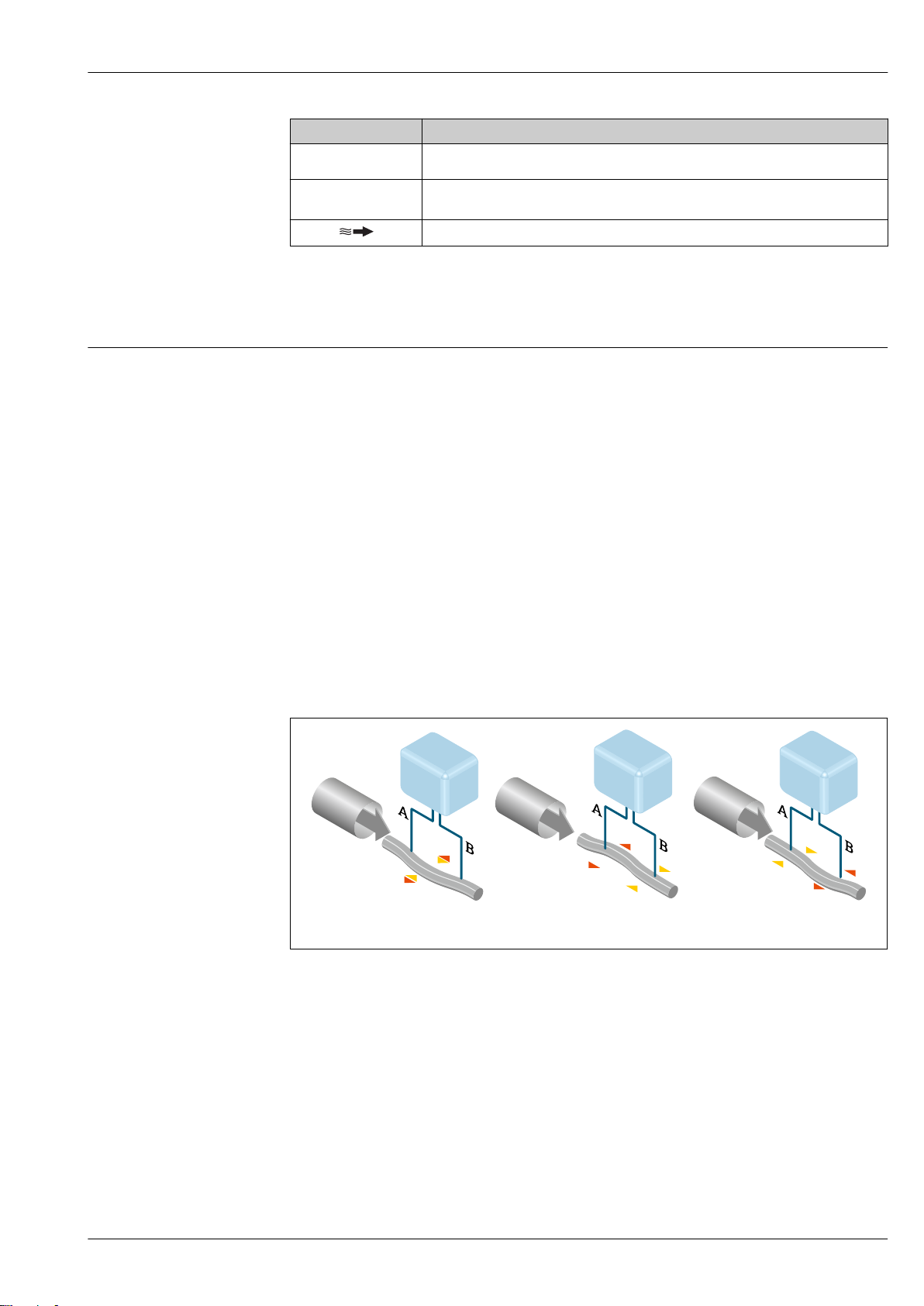
In the sensor, an oscillation is produced in the measuring tube. The Coriolis forces produced at the
measuring tube cause a phase shift in the tube oscillations (see illustration):
• If there is zero flow (i.e. when the fluid stands still), the oscillation measured at points A and B has
the same phase (no phase difference) (1).
• Mass flow causes deceleration of the oscillation at the inlet of the tubes (2) and acceleration at the
outlet (3).
A0029932
The phase difference (A-B) increases with increasing mass flow. Electrodynamic sensors register the
tube oscillations at the inlet and outlet. The measuring principle operates independently of
temperature, pressure, viscosity, conductivity and flow profile.
Density measurement
The measuring tube is continuously excited at its resonance frequency. A change in the mass and
thus the density of the oscillating system (comprising measuring tube and fluid) results in a
corresponding, automatic adjustment in the oscillation frequency. Resonance frequency is thus a
function of medium density. The microprocessor utilizes this relationship to obtain a density signal.
Volume measurement
Together with the measured mass flow, this is used to calculate the volume flow.
Endress+Hauser 5
Page 6

Proline Promass A 200
Temperature measurement
The temperature of the measuring tube is determined in order to calculate the compensation factor
due to temperature effects. This signal corresponds to the process temperature and is also available
as an output signal.
6 Endress+Hauser
Page 7
Proline Promass A 200
Measuring system
The device consists of a transmitter and a sensor.
The device is available as a compact version:
The transmitter and sensor form a mechanical unit.
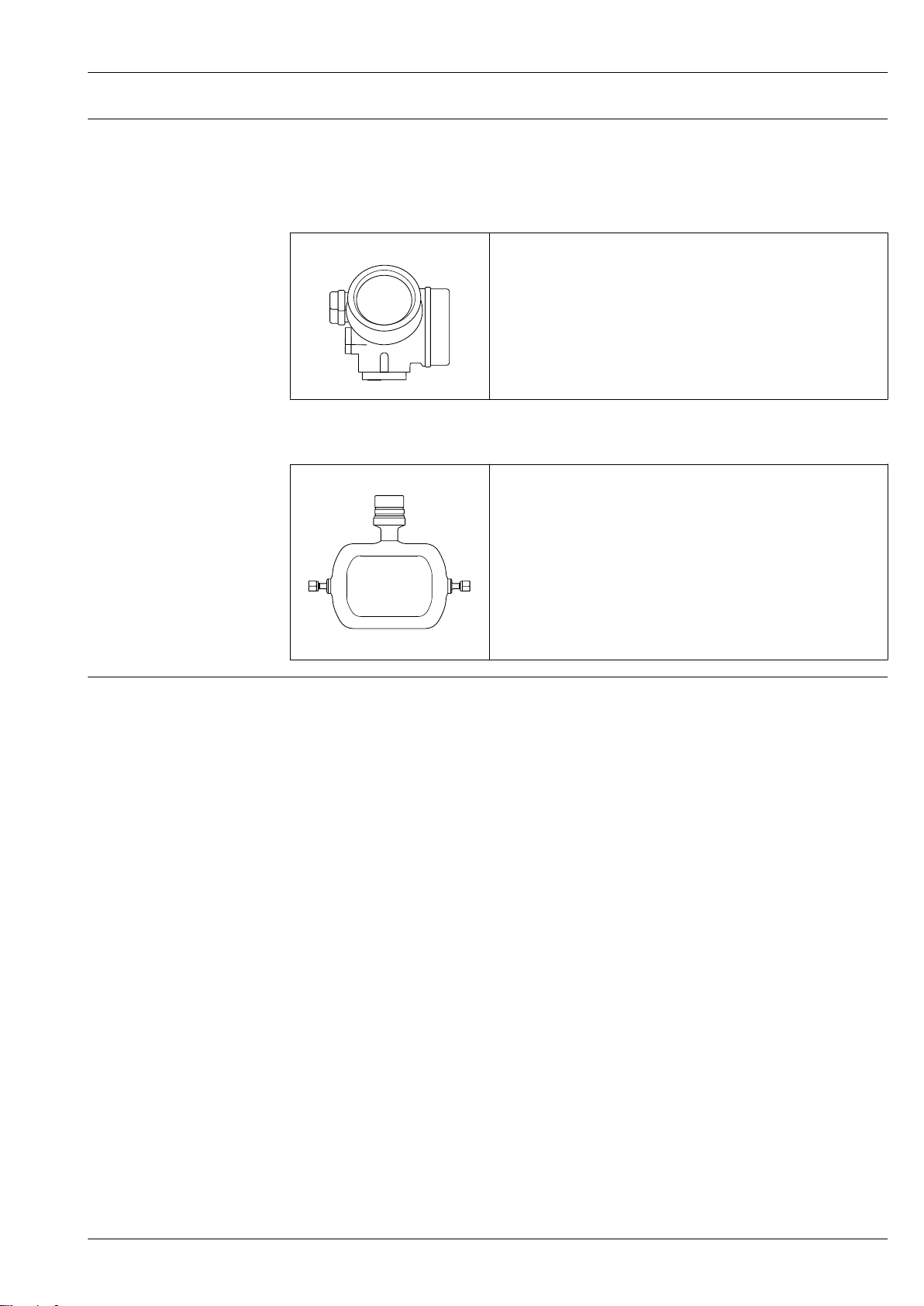
Transmitter
Promass 200 Device versions and materials:
• Compact, aluminum coated:
Aluminum, AlSi10Mg, coated
• Compact or remote version, stainless:
For maximum corrosion resistance: stainless steel CF3M
Configuration:
• External operation via four-line, illuminated local display with touch
control and guided menus ("Make-it-run" wizards) for applications
• Via operating tools (e.g. FieldCare)
A0013471
Sensor
Promass A • Single-tube system for high-precision measurement of minimum flow
rates
• Simultaneous measurement of flow, volume flow, density and
temperature (multivariable)
• Immune to process influences
• Nominal diameter range: DN 1 to 4 (¹⁄₂₄ to ¹⁄₈ ")
• Materials:
– Sensor: stainless steel, 1.4404 (316/316L)
– Measuring tube: stainless steel, 1.4435 (316/316L); Alloy C22,
2.4602 (UNS N06022)
A0036494
– Process connections: stainless steel, 1.4404 (316/316L); 1.4435
(316L); Alloy C22, 2.4602 (UNS N06022)
Safety IT security
Our warranty is valid only if the device is installed and used as described in the Operating
Instructions. The device is equipped with security mechanisms to protect it against any inadvertent
changes to the settings.
IT security measures, which provide additional protection for the device and associated data transfer,
must be implemented by the operators themselves in line with their security standards.
Device-specific IT security
The device offers a range of specific functions to support protective measures on the operator's side.
These functions can be configured by the user and guarantee greater in-operation safety if used
correctly. An overview of the most important functions is provided in the following section.
Protecting access via hardware write protection
Write access to the device parameters via the local display or operating tool (e.g. FieldCare,
DeviceCare) can be disabled via a write protection switch (DIP switch on the motherboard). When
hardware write protection is enabled, only read access to the parameters is possible.
Hardware write protection is disabled when the device is delivered.
Protecting access via a password
A password can be used to protect against write access to the device parameters.
This password locks write access to the device parameters via the local display or another operating
tool (e.g. FieldCare, DeviceCare) and, in terms of functionality, is equivalent to hardware write
protection. If the service interface CDI RJ-45 is used, read access is only possible if the password is
entered.
User-specific access code
Write access to the device parameters via the local display or operating tool (e.g. FieldCare,
DeviceCare) can be protected by the modifiable, user-specific access code.
Endress+Hauser 7
Page 8

Proline Promass A 200
Access via fieldbus
Cyclic fieldbus communication (read and write, e.g. measured value transmission) with a higherorder system is not affected by the restrictions mentioned above.
8 Endress+Hauser
Page 9
Proline Promass A 200
Input
Measured variable Direct measured variables
• Mass flow
• Density
• Temperature
Calculated measured variables
• Volume flow
• Corrected volume flow
• Reference density
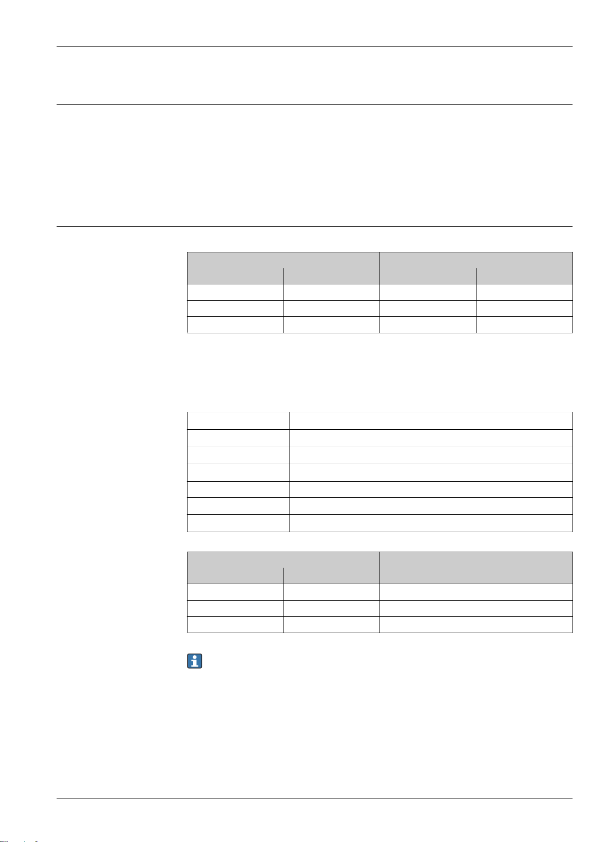
Measuring range Measuring ranges for liquids
DN Measuring range full scale values
[mm] [in] [kg/h] [lb/min]
1 ¹⁄₂₄ 0 to 20 0 to 0.735
2 ¹⁄₁₂ 0 to 100 0 to 3.675
4 ¹⁄₈ 0 to 450 0 to 16.54
min(F)
to
Measuring range for gases
The full scale value depends on the density and the sound velocity of the gas used and can be
calculated with the formula below:
= minimum (
max(G)
max(G)
max(F)
<
max(G)
ρ
G
x Constant dependent on nominal diameter
c
G
d
i
max(F)
· ρG : x ; ρG · cG · π/2 · (di)2 · 3600)
max(F)
Maximum full scale value for gas [kg/h]
Maximum full scale value for liquid [kg/h]
can never be greater than
max(G)
Gas density in [kg/m³] at operating conditions
Sound velocity (gas) [m/s]
Measuring tube internal diameter [m]
max(F)
max(F)
DN x
[mm] [in] [kg/m3]
1 ¹⁄₂₄ 32
2 ¹⁄₁₂ 32
4 ¹⁄₈ 32
To calculate the measuring range, use the Applicator sizing tool → 75
Calculation example for gas
• Sensor: Promass A, DN 2
• Gas: Air with a density of 11.9 kg/m³ (at 20 °C and 10 bar)
• Measuring range (liquid): 100 kg/h
• x = 32 kg/m³ (for Promass A DN 2)
Maximum possible full scale value:
max(G)
=
· ρG : x = 100 kg/h · 11.9 kg/m³ : 32 kg/m³ = 37.2 kg/h
max(F)
Endress+Hauser 9
Page 10

Recommended measuring range
"Flow limit" section → 42
Proline Promass A 200
Operable flow range
Over 1000 : 1.
Flow rates above the preset full scale value do not override the electronics unit, with the result that
the totalizer values are registered correctly.
Input signal External measured values
To increase the accuracy of certain measured variables or to calculate the corrected volume flow for
gases, the automation system can continuously write the operating pressure to the measuring
device. Endress+Hauser recommends the use of a pressure measuring device for absolute pressure,
e.g. Cerabar M or Cerabar S.
Various pressure transmitters and temperature measuring devices can be ordered from Endress
+Hauser: see "Accessories" section → 75
It is recommended to read in external measured values to calculate the following measured variables:
• Mass flow
• Corrected volume flow
HART protocol
The measured values are written from the automation system to the measuring device via the HART
protocol. The pressure transmitter must support the following protocol-specific functions:
• HART protocol
• Burst mode
Digital communication
The measured values can be written from the automation system to the measuring via:
• FOUNDATION Fieldbus
• PROFIBUS PA
Output
Output signal Current output
Current output 1 4-20 mA HART (passive)
Current output 2 4-20 mA (passive)
Resolution < 1 µA
Damping Adjustable: 0.0 to 999.9 s
Assignable measured
variables
Pulse/frequency/switch output
Function Can be set to pulse, frequency or switch output
Version Passive, open collector
Maximum input values • DC 35 V
• Mass flow
• Volume flow
• Corrected volume flow
• Density
• Reference density
• Temperature
• 50 mA
For information on the Ex connection values → 14
10 Endress+Hauser
Page 11

Proline Promass A 200
Voltage drop • For ≤ 2 mA: 2 V
• For 10 mA: 8 V
Residual current ≤ 0.05 mA
Pulse output
Pulse width Adjustable: 5 to 2 000 ms
Maximum pulse rate 100 Impulse/s
Pulse value Adjustable
Assignable measured
variables
Frequency output
Output frequency Adjustable: 0 to 1 000 Hz
Damping Adjustable: 0 to 999 s
Pulse/pause ratio 1:1
Assignable measured
variables
Switch output
Switching behavior Binary, conductive or non-conductive
Switching delay Adjustable: 0 to 100 s
Number of switching
cycles
Assignable functions • Off
• Mass flow
• Volume flow
• Corrected volume flow
• Mass flow
• Volume flow
• Corrected volume flow
• Density
• Reference density
• Temperature
Unlimited
• On
• Diagnostic behavior
• Limit value
– Mass flow
– Volume flow
– Corrected volume flow
– Density
– Reference density
– Temperature
– Totalizer 1-3
• Flow direction monitoring
• Status
– Partially filled pipe detection
– Low flow cut off
FOUNDATION Fieldbus
FOUNDATION Fieldbus H1, IEC 61158-2, galvanically isolated
Data transfer 31.25 kbit/s
Current consumption 18 mA
Permitted supply voltage 9 to 32 V
Bus connection With integrated reverse polarity protection
PROFIBUS PA
PROFIBUS PA In accordance with EN 50170 Volume 2, IEC 61158-2 (MBP), galvanically
isolated
Data transmission 31.25 kbit/s
Endress+Hauser 11
Page 12

Current consumption 16 mA
Permitted supply voltage 9 to 32 V
Bus connection With integrated reverse polarity protection
Proline Promass A 200
Signal on alarm
Depending on the interface, failure information is displayed as follows:
Current output 4 to 20 mA
4 to 20 mA
Failure mode Choose from:
• 4 to 20 mA in accordance with NAMUR recommendation NE 43
• 4 to 20 mA in accordance with US
• Min. value: 3.59 mA
• Max. value: 22.5 mA
• Freely definable value between: 3.59 to 22.5 mA
• Actual value
• Last valid value
Pulse/frequency/switch output
Pulse output
Failure mode Choose from:
• Actual value
• No pulses
Frequency output
Failure mode Choose from:
• Actual value
• 0 Hz
• Defined value: 0 to 1 250 Hz
Switch output
Failure mode Choose from:
• Current status
• Open
• Closed
FOUNDATION Fieldbus
Status and alarm
messages
Failure current FDE (Fault
Disconnection Electronic)
Diagnostics in accordance with FF-891
0 mA
PROFIBUS PA
Status and alarm
messages
Failure current FDE (Fault
Disconnection Electronic)
Diagnostics in accordance with PROFIBUS PA Profile 3.02
0 mA
12 Endress+Hauser
Page 13

Proline Promass A 200
0
100
200
300
400
500
16 18 20
22 24
26 28 30 32
U [V]
S
RB[Ω]
34 36
A B
Local display
Plain text display With information on cause and remedial measures
Backlight Additionally for device version with SD03 local display: red lighting indicates a
device error.
Status signal as per NAMUR recommendation NE 107
Interface/protocol
• Via digital communication:
– HART protocol
– FOUNDATION Fieldbus
– PROFIBUS PA
• Via service interface
CDI service interface
Plain text display With information on cause and remedial measures
Additional information on remote operation → 66
Load
Load for current output: 0 to 500 Ω, depending on the external supply voltage of the power supply
unit
Calculation of the maximum load
Depending on the supply voltage of the power supply unit (US), the maximum load (RB) including
line resistance must be observed to ensure adequate terminal voltage at the device. In doing so,
observe the minimum terminal voltage
• For US = 17.9 to 18.9 V: RB ≤ (US - 17.9 V): 0.0036 A
• For US = 18.9 to 24 V: RB ≤ (US - 13 V): 0.022 A
• For US = ≥ 24 V: RB ≤ 500 Ω
A0013563
A Operating range for order code for "Output", option A "4-20 mA HART"/option B "4-20 mA HART, pulse/
frequency/switch output" with Ex i and option C "4-20 mA HART + 4-20 mA analog"
B Operating range for order code for "Output", option A "4-20 mA HART"/option B "4-20 mA HART, pulse/
frequency/switch output" with non-Ex and Ex d
Sample calculation
Supply voltage of power supply unit: US =19 V
Maximum load: RB ≤ (19 V - 13 V): 0.022 A = 273 Ω
Endress+Hauser 13
Page 14

Ex connection data Safety-related values
Type of protection Ex d
Order code for "Output" Output type Safety-related values
Option A 4-20mA HART U
Option B 4-20mA HART U
Option C 4-20mA HART
Option E FOUNDATION Fieldbus U
Option G PROFIBUS PA U
Pulse/frequency/switch output U
4-20mA analog
Pulse/frequency/switch output U
Pulse/frequency/switch output U
Proline Promass A 200
= DC 35 V
nom
U
= 250 V
max
= DC 35 V
nom
U
= 250 V
max
= DC 35 V
nom
U
= 250 V
max
P
max
U
nom
U
max
nom
U
max
P
max
nom
U
max
P
max
nom
U
max
P
max
nom
U
max
P
max
1)
= 1 W
= DC 30 V
= 250 V
= DC 32 V
= 250 V
= 0.88 W
= DC 35 V
= 250 V
1)
= 1 W
= DC 32 V
= 250 V
= 0.88 W
= DC 35 V
= 250 V
1)
= 1 W
1) Internal circuit limited by Ri = 760.5 Ω
Type of protection Ex ec
Order code for "Output" Output type Safety-related values
Option A 4-20mA HART U
Option B 4-20mA HART U
Pulse/frequency/switch output U
Option C 4-20mA HART
4-20mA analog
Option E FOUNDATION Fieldbus U
Pulse/frequency/switch output U
Option G PROFIBUS PA U
Pulse/frequency/switch output U
nom
U
max
nom
U
max
nom
U
max
P
max
U
nom
U
max
nom
U
max
P
max
nom
U
max
P
max
nom
U
max
P
max
nom
U
max
P
max
= DC 35 V
= 250 V
= DC 35 V
= 250 V
= DC 35 V
= 250 V
1)
= 1 W
= DC 30 V
= 250 V
= DC 32 V
= 250 V
= 0.88 W
= DC 35 V
= 250 V
1)
= 1 W
= DC 32 V
= 250 V
= 0.88 W
= DC 35 V
= 250 V
1)
= 1 W
1) Internal circuit limited by Ri = 760.5 Ω
14 Endress+Hauser
Page 15

Proline Promass A 200
Type of protection XP
Order code for "Output" Output type Safety-related values
Option A 4-20mA HART U
Option B 4-20mA HART U
Pulse/frequency/switch output U
Option C 4-20mA HART
4-20mA analog
Option E FOUNDATION Fieldbus U
Pulse/frequency/switch output U
Option G PROFIBUS PA U
Pulse/frequency/switch output U
nom
U
max
nom
U
max
nom
U
max
P
max
U
nom
U
max
nom
U
max
P
max
nom
U
max
P
max
nom
U
max
P
max
nom
U
max
P
max
= DC 35 V
= 250 V
= DC 35 V
= 250 V
= DC 35 V
= 250 V
1)
= 1 W
= DC 30 V
= 250 V
= DC 32 V
= 250 V
= 0.88 W
= DC 35 V
= 250 V
1)
= 1 W
= DC 32 V
= 250 V
= 0.88 W
= DC 35 V
= 250 V
1)
= 1 W
1) Internal circuit limited by Ri = 760.5 Ω
Intrinsically safe values
Type of protection Ex ia
Order code for "Output" Output type Intrinsically safe values
Option A 4-20mA HART Ui = DC 30 V
Ii = 300 mA
Pi = 1 W
Li = 0 μH
Ci = 5 nF
Option B 4-20mA HART Ui = DC 30 V
Ii = 300 mA
Pi = 1 W
Li = 0 μH
Ci = 5 nF
Pulse/frequency/switch output Ui = DC 30 V
Ii = 300 mA
Pi = 1 W
Li = 0 μH
Ci = 6 nF
Option C 4-20mA HART Ui = DC 30 V
4-20mA analog
Option E FOUNDATION Fieldbus STANDARD
Ii = 300 mA
Pi = 1 W
Li = 0 μH
Ci = 30 nF
Ui = 30 V
li = 300 mA
Pi = 1.2 W
Li = 10 µH
Ci = 5 nF
FISCO
Ui = 17.5 V
li = 550 mA
Pi = 5.5 W
Li = 10 µH
Ci = 5 nF
Endress+Hauser 15
Page 16

Proline Promass A 200
Order code for "Output" Output type Intrinsically safe values
Pulse/frequency/switch output Ui = 30 V
li = 300 mA
Pi = 1 W
Li = 0 µH
Ci = 6 nF
Option G PROFIBUS PA STANDARD
Ui = 30 V
li = 300 mA
Pi = 1.2 W
Li = 10 µH
Ci = 5 nF
Pulse/frequency/switch output Ui = 30 V
li = 300 mA
Pi = 1 W
Li = 0 µH
Ci = 6 nF
Type of protection Ex ic
Order code for "Output" Output type Intrinsically safe values
Option A 4-20mA HART Ui = DC 35 V
Ii = n.a.
Pi = 1 W
Li = 0 μH
Ci = 5 nF
Option B 4-20mA HART Ui = DC 35 V
Ii = n.a.
Pi = 1 W
Li = 0 μH
Ci = 5 nF
Pulse/frequency/switch output Ui = DC 35 V
Ii = n.a.
Pi = 1 W
Li = 0 μH
Ci = 6 nF
Option C 4-20mA HART Ui = DC 30 V
4-20mA analog
Option E FOUNDATION Fieldbus STANDARD
Pulse/frequency/switch output Ui = 35 V
Ii = n.a.
Pi = 1 W
Li = 0 μH
Ci = 30 nF
Ui = 32 V
li = 300 mA
Pi = n.a.
Li = 10 µH
Ci = 5 nF
li = 300 mA
Pi = 1 W
Li = 0 µH
Ci = 6 nF
FISCO
Ui = 17.5 V
li = 550 mA
Pi = 5.5 W
Li = 10 µH
Ci = 5 nF
FISCO
Ui = 17.5 V
li = n.a.
Pi = n.a.
Li = 10 µH
Ci = 5 nF
16 Endress+Hauser
Page 17

Proline Promass A 200
Order code for "Output" Output type Intrinsically safe values
Option G PROFIBUS PA STANDARD
Ui = 32 V
li = 300 mA
Pi = n.a.
Li = 10 µH
Ci = 5 nF
Pulse/frequency/switch output Ui = 35 V
li = 300 mA
Pi = 1 W
Li = 0 µH
Ci = 6 nF
FISCO
Ui = 17.5 V
li = n.a.
Pi = n.a.
Li = 10 µH
Ci = 5 nF
Type of protection IS
Order code for "Output" Output type Intrinsically safe values
Option A 4-20mA HART Ui = DC 30 V
Ii = 300 mA
Pi = 1 W
Li = 0 μH
Ci = 5 nF
Option B 4-20mA HART Ui = DC 30 V
Ii = 300 mA
Pi = 1 W
Li = 0 μH
Ci = 5 nF
Pulse/frequency/switch output Ui = DC 30 V
Ii = 300 mA
Pi = 1 W
Li = 0 μH
Ci = 6 nF
Option C 4-20mA HART Ui = DC 30 V
4-20mA analog
Option E FOUNDATION Fieldbus STANDARD
Pulse/frequency/switch output Ui = 30 V
Option G PROFIBUS PA STANDARD
Pulse/frequency/switch output Ui = 30 V
Ii = 300 mA
Pi = 1 W
Li = 0 μH
Ci = 30 nF
Ui = 30 V
li = 300 mA
Pi = 1.2 W
Li = 10 µH
Ci = 5 nF
li = 300 mA
Pi = 1 W
Li = 0 µH
Ci = 6 nF
Ui = 30 V
li = 300 mA
Pi = 1.2 W
Li = 10 µH
Ci = 5 nF
li = 300 mA
Pi = 1 W
Li = 0 µH
Ci = 6 nF
FISCO
Ui = 17.5 V
li = 550 mA
Pi = 5.5 W
Li = 10 µH
Ci = 5 nF
FISCO
Ui = 17.5 V
li = 550 mA
Pi = 5.5 W
Li = 10 µH
Ci = 5 nF
Low flow cut off
The switch points for low flow cut off are user-selectable.
Endress+Hauser 17
Page 18

Proline Promass A 200
Galvanic isolation
All outputs are galvanically isolated from one another.
Protocol-specific data HART
Manufacturer ID 0x11
Device type ID 0x54
HART protocol revision 7
Device description files
(DTM, DD)
HART load • Min. 250 Ω
System integration For information on system integration, see Operating Instructions.
FOUNDATION Fieldbus
Manufacturer ID 0x452B48
Ident number 0x1054
Device revision 1
DD revision Information and files under:
CFF revision
Device Tester Version (ITK
version)
ITK Test Campaign Number IT094200
Link Master capability (LAS) Yes
Choice of "Link Master" and
"Basic Device"
Node address Factory setting: 247 (0xF7)
Supported functions The following methods are supported:
Virtual Communication Relationships (VCRs)
Number of VCRs 44
Number of link objects in VFD 50
Permanent entries 1
Client VCRs 0
Server VCRs 10
Source VCRs 43
Sink VCRs 0
Subscriber VCRs 43
Publisher VCRs 43
Device Link Capabilities
Slot time 4
Min. delay between PDU 8
Information and files under:
www.endress.com
• Max. 500 Ω
• Measured variables via HART protocol
• Burst Mode functionality
• www.endress.com
• www.fieldbus.org
6.1.1
Yes
Factory setting: Basic Device
• Restart
• ENP Restart
• Diagnostic
18 Endress+Hauser
Page 19

Proline Promass A 200
+
1
–
2
–
4
+
3
1
2
3
+
1
–
2
–
4
+
3
1
2
3
Max. response delay Min. 5
System integration For information on system integration, see Operating Instructions.
• Cyclic data transmission
• Description of the modules
• Execution times
• Methods
PROFIBUS PA
Manufacturer ID 0x11
Ident number 0x155F
Profile version 3.02
Device description files (GSD,
DTM, DD)
Supported functions • Identification & Maintenance
Configuration of the device
address
System integration For information on system integration, see Operating Instructions.
Information and files under:
• www.endress.com
• www.profibus.org
Simple device identification via control system and nameplate
• PROFIBUS upload/download
Reading and writing parameters is up to ten times faster with PROFIBUS
upload/download
• Condensed status
Simplest and self-explanatory diagnostic information by categorizing
diagnostic messages that occur
• DIP switches on the I/O electronics module
• Local display
• Via operating tools (e. g. FieldCare)
• Cyclic data transmission
• Block model
• Description of the modules
Power supply
Terminal assignment Transmitter
Connection versions
A0013570
Maximum number of terminals, without integrated
overvoltage protection
1
Output 1 (passive): supply voltage and signal transmission
2
Output 2 (passive): supply voltage and signal transmission
3
Ground terminal for cable shield
Maximum number of terminals, with integrated
overvoltage protection
A0018161
Endress+Hauser 19
Page 20
Order code for "Output" Terminal numbers
1
2
4
3
1
2
4
3
Option B
Option C
Option E
Option G
1) Output 1 must always be used; output 2 is optional.
2) FOUNDATION Fieldbus with integrated reverse polarity protection.
3) PROFIBUS PA with integrated reverse polarity protection.
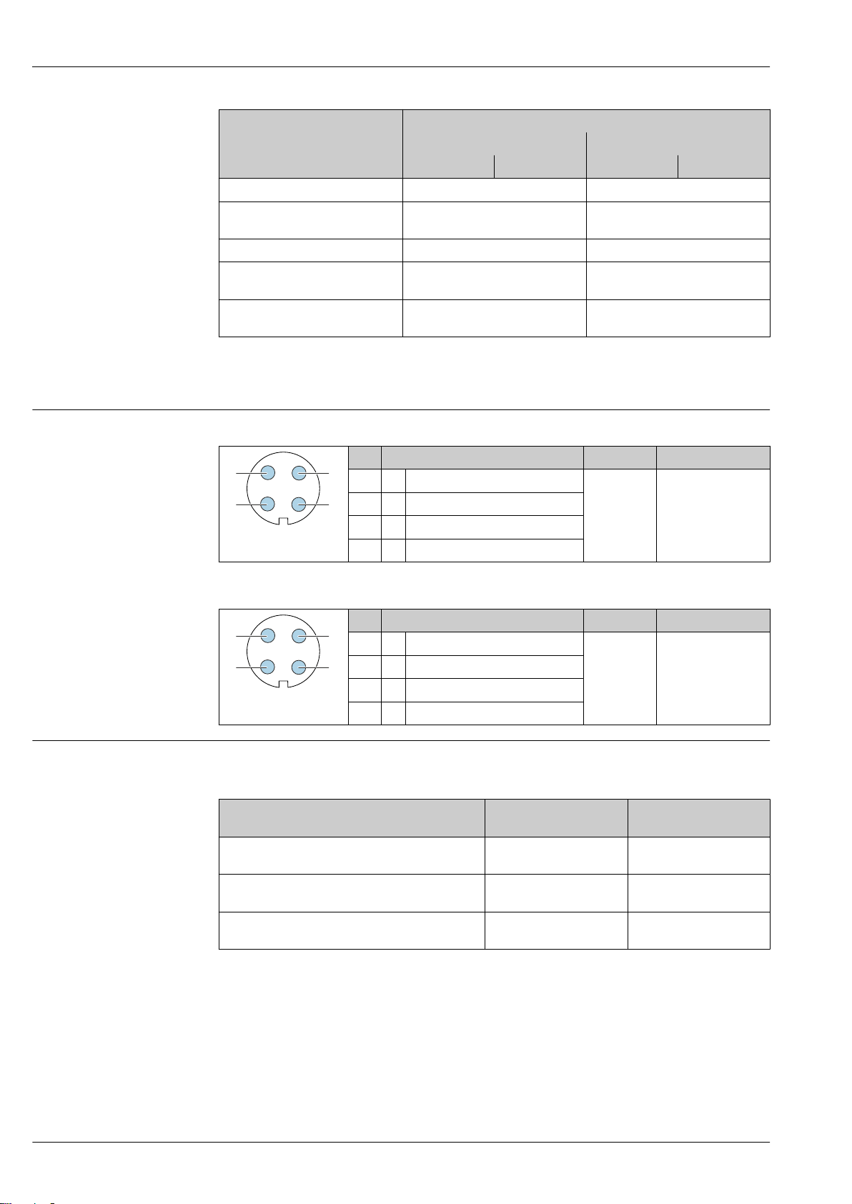
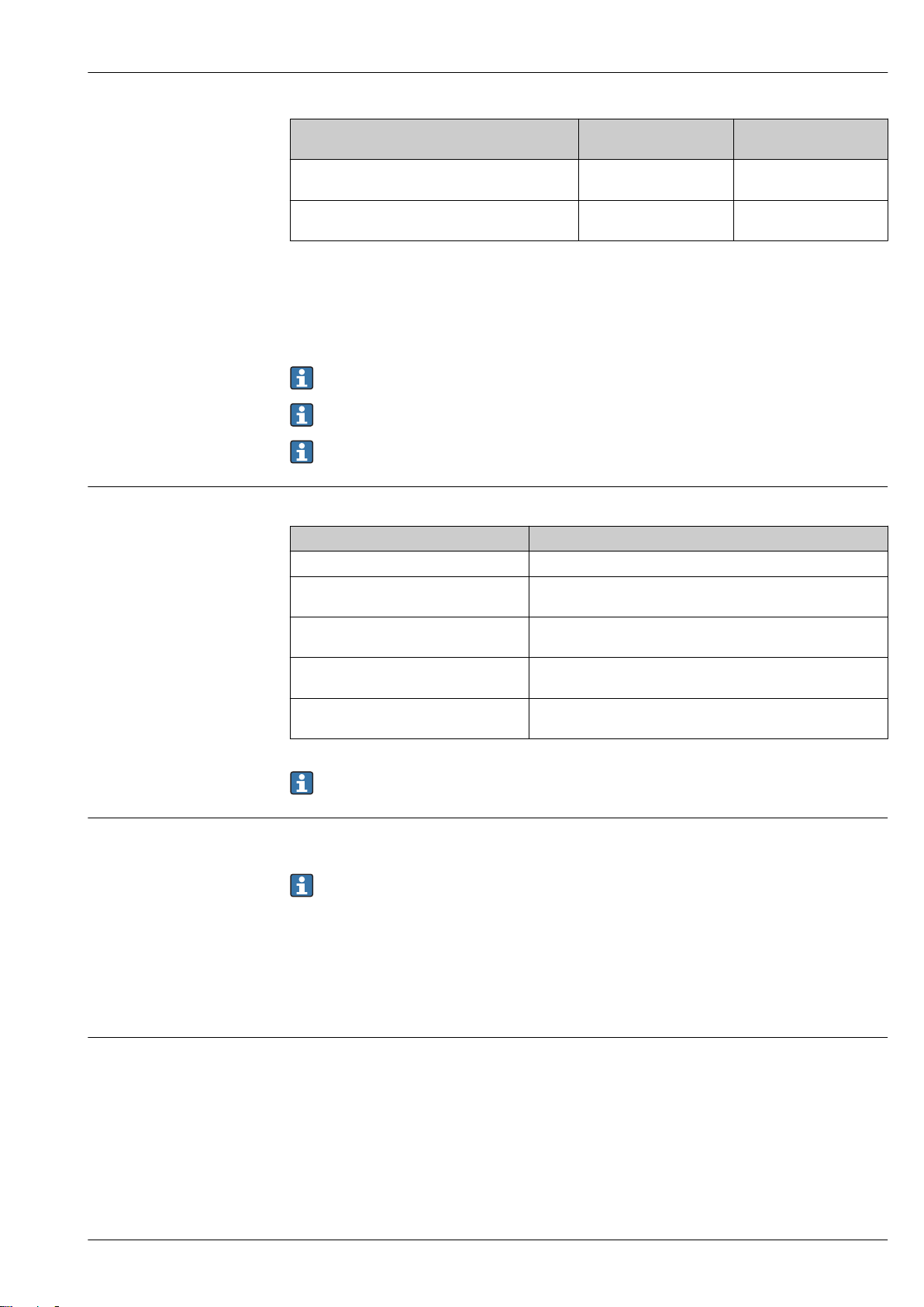
Pin assignment, device plug PROFIBUS PA
Proline Promass A 200
Output 1 Output 2
1 (+) 2 (-) 3 (+) 4 (-)
Option A 4-20 mA HART (passive) -
1)
1)
1) 2)
1) 3)
Pin Assignment Coding Plug/socket
1 + PROFIBUS PA + A Plug
2 Grounding
3 - PROFIBUS PA –
4 Not assigned
4-20 mA HART (passive) Pulse/frequency/switch output
(passive)
4-20 mA HART (passive) 4-20 mA analog (passive)
FOUNDATION Fieldbus
PROFIBUS PA
Pulse/frequency/switch output
(passive)
Pulse/frequency/switch output
(passive)
FOUNDATION Fieldbus
Supply voltage Transmitter
An external power supply is required for each output.
Order code for "Output"
Option A
Option B
switch output
Option C
1) 2)
1) 2)
1) 2)
Pin Assignment Coding Plug/socket
1 + Signal + A Plug
2 - Signal –
3 Grounding
4 Not assigned
Minimum
terminal voltage
: 4-20 mA HART • For 4 mA: ≥ DC 17.9 V
• For 20 mA: ≥ DC 13.5 V
: 4-20 mA HART, pulse/frequency/
• For 4 mA: ≥ DC 17.9 V
• For 20 mA: ≥ DC 13.5 V
: 4-20 mA HART + 4-20 mA analog • For 4 mA: ≥ DC 17.9 V
• For 20 mA: ≥ DC 13.5 V
Maximum
terminal voltage
DC 35 V
DC 35 V
DC 30 V
20 Endress+Hauser
Page 21
Proline Promass A 200
Order code for "Output"
Option E
frequency/switch output
Option G
output
1) External supply voltage of the power supply unit with load.
2) For device versions with SD03 local display: The terminal voltage must be increased by DC 2 V if
3) For device version with SD03 local display: The terminal voltage must be increased by DC 0.5 V if
3)
3)
: PROFIBUS PA, pulse/frequency/switch
backlighting is used.
backlighting is used.
For information about the load see → 13
Various power supply units can be ordered from Endress+Hauser: → 75
For information on the Ex connection values → 14
Power consumption Transmitter
Order code for "Output; input" Maximum power consumption
Option A: 4-20 mA HART 770 mW
Option B: 4-20 mA HART, pulse/
frequency/switch output
Option C: 4-20 mA HART + 4-20 mA
analog
Option E: FOUNDATION Fieldbus, pulse/
frequency/switch output
Option G: PROFIBUS PA, pulse/frequency/
switch output
: FOUNDATION Fieldbus, pulse/
Minimum
terminal voltage
≥ DC 9 V
≥ DC 9 V
• Operation with output 1: 770 mW
• Operation with output 1 and 2: 2 770 mW
• Operation with output 1: 660 mW
• Operation with output 1 and 2: 1 320 mW
• Operation with output 1: 576 mW
• Operation with output 1 and 2: 2 576 mW
• Operation with output 1: 512 mW
• Operation with output 1 and 2: 2 512 mW
Maximum
terminal voltage
DC 32 V
DC 32 V
For information on the Ex connection values → 14
Current consumption Current output
For every 4-20 mA or 4-20 mA HART current output: 3.6 to 22.5 mA
If the option Defined value is selected in the Failure mode parameter : 3.59 to 22.5 mA
FOUNDATION Fieldbus
18 mA
PROFIBUS PA
16 mA
Power supply failure
Depending on the device version, the configuration is retained in the device memoryor in the
pluggable data memory (HistoROM DAT).
Endress+Hauser 21
Page 22
Electrical connection Connecting the transmitter
1
2
2
3
4...20 mA
41
5
1
2
3
12345
1 Cable entry for output 1
2 Cable entry for output 2
Connection examples
Current output 4-20 mA HART
Proline Promass A 200
A0015510
A0028762
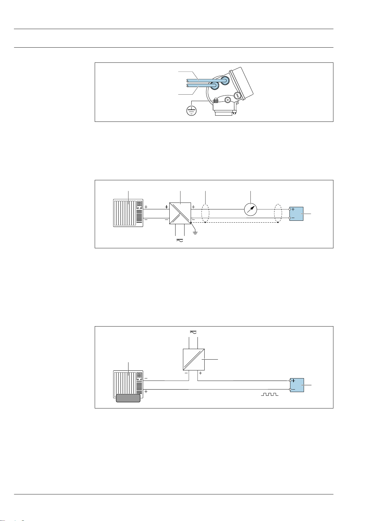
1 Connection example for 4 to 20 mA HART current output (passive)
1 Automation system with current input (e.g. PLC)
2 Power supply
3 Cable shield: the cable shield must be grounded at both ends to comply with EMC requirements; observe cable
specifications
4 Analog display unit: observe maximum load
5 Transmitter
Pulse/frequency output
A0028761
2 Connection example for pulse/frequency output (passive)
1 Automation system with pulse/frequency input (e.g. PLC)
2 Power supply
3 Transmitter: Observe input values
22 Endress+Hauser
Page 23
Proline Promass A 200
1
2
3
21 3 4
78
6 6
6
6
5
6
6
5
Switch output
A0028760
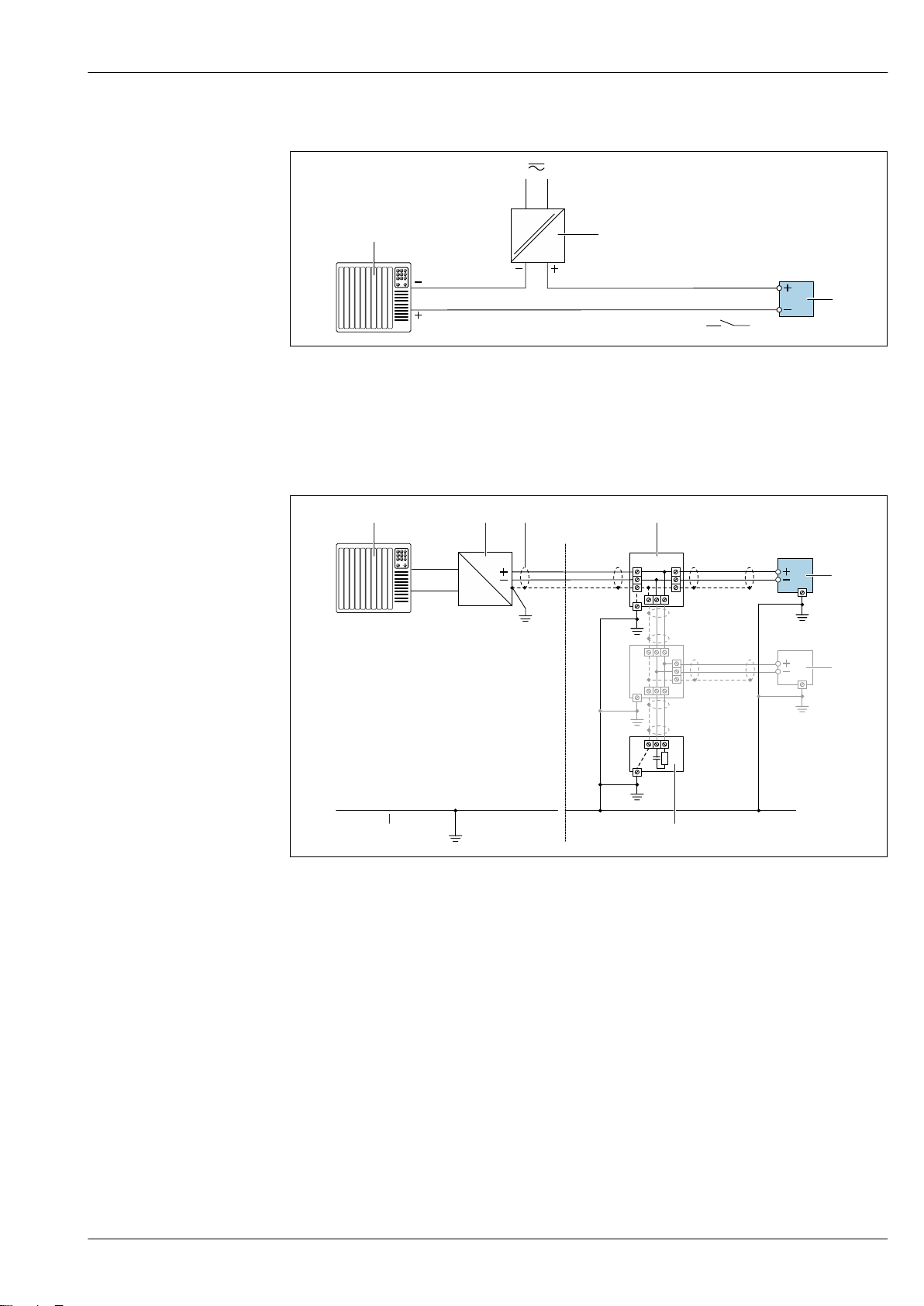
3 Connection example for switch output (passive)
1 Automation system with switch input (e.g. PLC)
2 Power supply
3 Transmitter: Observe input values
FOUNDATION Fieldbus
A0028768
4 Connection example for FOUNDATION Fieldbus
1 Control system (e.g. PLC)
2 Power Conditioner (FOUNDATION Fieldbus)
3 Cable shield: the cable shield must be grounded at both ends to comply with EMC requirements; observe cable
specifications
4 T-box
5 Measuring device
6 Local grounding
7 Bus terminator
8 Potential matching line
Endress+Hauser 23
Page 24

PROFIBUS PA
21 3 4
78
6 6
6
6
5
6
6
5
2
4...20 mA
4
1
2
3
3
6
5
Proline Promass A 200
A0028768
5 Connection example for PROFIBUS PA
1 Control system (e.g. PLC)
2 PROFIBUS PA segment coupler
3 Cable shield: the cable shield must be grounded at both ends to comply with EMC requirements; observe cable
specifications
4 T-box
5 Measuring device
6 Local grounding
7 Bus terminator
8 Potential matching line
HART input
24 Endress+Hauser
6 Connection example for HART input with a common negative (passive)
1 Automation system with HART output (e.g. PLC)
2 Active barrier for power supply (e.g. RN221N)
3 Cable shield: the cable shield must be grounded at both ends to comply with EMC requirements; observe cable
specifications
4 Analog display unit: observe maximum load
5 Pressure measuring device (e.g. Cerabar M, Cerabar S): see requirements
6 Transmitter
A0028763
Page 25

Proline Promass A 200
1
2
2
3
4...20 mA
41
5
1
2
3
12345
Electrical connection Connecting the transmitter
1 Cable entry for output 1
2 Cable entry for output 2
Connection examples
Current output 4-20 mA HART
A0015510
A0028762
7 Connection example for 4 to 20 mA HART current output (passive)
1 Automation system with current input (e.g. PLC)
2 Power supply
3 Cable shield: the cable shield must be grounded at both ends to comply with EMC requirements; observe cable
specifications
4 Analog display unit: observe maximum load
5 Transmitter
Pulse/frequency output
A0028761
8 Connection example for pulse/frequency output (passive)
1 Automation system with pulse/frequency input (e.g. PLC)
2 Power supply
3 Transmitter: Observe input values
Endress+Hauser 25
Page 26

Switch output
1
2
3
21 3 4
78
6 6
6
6
5
6
6
5
9 Connection example for switch output (passive)
1 Automation system with switch input (e.g. PLC)
2 Power supply
3 Transmitter: Observe input values
FOUNDATION Fieldbus
Proline Promass A 200
A0028760
A0028768
10 Connection example for FOUNDATION Fieldbus
1 Control system (e.g. PLC)
2 Power Conditioner (FOUNDATION Fieldbus)
3 Cable shield: the cable shield must be grounded at both ends to comply with EMC requirements; observe cable
specifications
4 T-box
5 Measuring device
6 Local grounding
7 Bus terminator
8 Potential matching line
26 Endress+Hauser
Page 27

Proline Promass A 200
21 3 4
78
6 6
6
6
5
6
6
5
2
4...20 mA
4
1
2
3
3
6
5
PROFIBUS PA
A0028768
11 Connection example for PROFIBUS PA
1 Control system (e.g. PLC)
2 PROFIBUS PA segment coupler
3 Cable shield: the cable shield must be grounded at both ends to comply with EMC requirements; observe cable
specifications
4 T-box
5 Measuring device
6 Local grounding
7 Bus terminator
8 Potential matching line
HART input
Endress+Hauser 27
12 Connection example for HART input with a common negative (passive)
1 Automation system with HART output (e.g. PLC)
2 Active barrier for power supply (e.g. RN221N)
3 Cable shield: the cable shield must be grounded at both ends to comply with EMC requirements; observe cable
4 Analog display unit: observe maximum load
5 Pressure measuring device (e.g. Cerabar M, Cerabar S): see requirements
6 Transmitter
specifications
A0028763
Page 28

Potential equalization Requirements
No special measures for potential equalization are required.
For devices intended for use in hazardous locations, please observe the guidelines in the
Ex documentation (XA).
Proline Promass A 200
Terminals
• For device version without integrated overvoltage protection: plug-in spring terminals for wire
cross-sections 0.5 to 2.5 mm2 (20 to 14 AWG)
• For device version with integrated overvoltage protection: screw terminals for wire cross-sections
0.2 to 2.5 mm2 (24 to 14 AWG)
Cable entries
• Cable gland (not for Ex d): M20 × 1.5 with cable ⌀ 6 to 12 mm (0.24 to 0.47 in)
• Thread for cable entry:
– For non-hazardous and hazardous areas: NPT ½"
– For non-hazardous and hazardous areas (not for XP): G ½"
– For Ex d: M20 × 1.5
Cable specification Permitted temperature range
• The installation guidelines that apply in the country of installation must be observed.
• The cables must be suitable for the minimum and maximum temperatures to be expected.
Signal cable
Current output 4 to 20 mA HART
A shielded cable is recommended. Observe grounding concept of the plant.
Current output 4 to 20 mA
Standard installation cable is sufficient.
Pulse/frequency/switch output
Standard installation cable is sufficient.
Overvoltage protection
FOUNDATION Fieldbus
Twisted, shielded two-wire cable.
For further information on planning and installing FOUNDATION Fieldbus networks see:
• Operating Instructions for "FOUNDATION Fieldbus Overview" (BA00013S)
• FOUNDATION Fieldbus Guideline
• IEC 61158-2 (MBP)
PROFIBUS PA
Twisted, shielded two-wire cable. Cable type A is recommended .
For further information on planning and installing PROFIBUS networks see:
• Operating Instructions "PROFIBUS DP/PA: Guidelines for planning and commissioning"
(BA00034S)
• PNO Directive 2.092 "PROFIBUS PA User and Installation Guideline"
• IEC 61158-2 (MBP)
The device can be ordered with integrated overvoltage protection for diverse approvals:
Order code for "Accessory mounted", option NA "Overvoltage protection"
Input voltage range Values correspond to supply voltage specifications → 20
Resistance per channel 2 ⋅ 0.5 Ω max.
DC sparkover voltage 400 to 700 V
Trip surge voltage < 800 V
Capacitance at 1 MHz < 1.5 pF
1)
28 Endress+Hauser
Page 29

Proline Promass A 200
Reference operating conditions
Maximum measured error
Nominal discharge current
(8/20 μs)
Temperature range –40 to +85 °C (–40 to +185 °F)
1) The voltage is reduced by the amount of the internal resistance I
10 kA
min
⋅ R
i
Depending on the temperature class, restrictions apply to the ambient temperature for device
versions with overvoltage protection .
For detailed information on the temperature tables, see the "Safety Instructions" (XA) for the
device.
Performance characteristics
• Error limits based on ISO 11631
• Water with +15 to +45 °C (+59 to +113 °F) at2 to 6 bar (29 to 87 psi)
• Specifications as per calibration protocol
• Accuracy based on accredited calibration rigs that are traced to ISO 17025.
To obtain measured errors, use the Applicator sizing tool → 75
o.r. = of reading; 1 g/cm³ = 1 kg/l; T = medium temperature
Base accuracy
Design fundamentals → 32
Mass flow and volume flow (liquids)
±0.10 % o.r.
Mass flow (gases)
±0.35 % o.r.
Density (liquids)
Under
reference operating conditions
[g/cm³] [g/cm³] [g/cm³]
±0.0005 ±0.02 ±0.002
1) Valid over the entire temperature and density range
2) Valid range for special density calibration: 0 to 2 g/cm³, +5 to +80 °C (+41 to +176 °F)
3) Order code for "Application package", option EE "Special density" only in combination with the order code
for "Measuring tube mat., wetted surface", option BB, BF, HA, SA
Standard density
calibration
1)
Wide-range
Density specification
2) 3)
Temperature
±0.5 °C ± 0.005 · T °C (±0.9 °F ± 0.003 · (T – 32) °F)
Endress+Hauser 29
Page 30

Proline Promass A 200
Zero point stability
Standard version: order code for "Measuring tube mat., wetted surface", option BB, BF, HA, SA
DN Zero point stability
[mm] [in] [kg/h] [lb/min]
1 ¹⁄₂₄ 0.0010 0.000036
2 ¹⁄₁₂ 0.0050 0.00018
4 ¹⁄₈ 0.0200 0.00072
High-pressure version: order code for "Measuring tube mat., wetted surface", option HB
DN Zero point stability
[mm] [in] [kg/h] [lb/min]
1 ¹⁄₂₄ 0.0016 0.0000576
2 ¹⁄₁₂ 0.0080 0.000288
4 ¹⁄₈ 0.0320 0.001152
Flow values
Flow values as turndown parameter depending on nominal diameter.
SI units
DN 1:1 1:10 1:20 1:50 1:100 1:500
[mm]
1 20 2 1 0.4 0.2 0.04
2 100 10 5 2 1 0.2
4 450 45 22.5 9 4.5 0.9
[kg/h] [kg/h] [kg/h] [kg/h] [kg/h] [kg/h]
US units
DN 1:1 1:10 1:20 1:50 1:100 1:500
[inch] [lb/min] [lb/min] [lb/min] [lb/min] [lb/min] [lb/min]
¹⁄₂₄ 0.735 0.074 0.037 0.015 0.007 0.001
¹⁄₁₂ 3.675 0.368 0.184 0.074 0.037 0.007
¹⁄₈ 16.54 1.654 0.827 0.331 0.165 0.033
Accuracy of outputs
The outputs have the following base accuracy specifications.
Current output
Accuracy ±10 µA
Pulse/frequency output
o.r. = of reading
Accuracy Max. ±100 ppm o.r.
Repeatability
o.r. = of reading; 1 g/cm3 = 1 kg/l; T = medium temperature
30 Endress+Hauser
Page 31

Proline Promass A 200
Base repeatability
Design fundamentals → 32
Mass flow and volume flow (liquids)
±0.05 % o.r.
Mass flow (gases)
±0.15 % o.r.
Density (liquids)
±0.00025 g/cm
3
Temperature
±0.25 °C ± 0.0025 · T °C (±0.45 °F ± 0.0015 · (T–32) °F)
Response time
Influence of ambient temperature
Influence of medium temperature
• The response time depends on the configuration (damping).
• Response time in the event of erratic changes in the measured variable: After 500 ms → 95 % of
full scale value
Current output
o.r. = of reading
Additional error, in relation to the span of 16 mA:
Temperature coefficient at
zero point (4 mA)
Temperature coefficient
with span (20 mA)
0.02 %/10 K
0.05 %/10 K
Pulse/frequency output
o.r. = of reading
Temperature coefficient Max. ±100 ppm o.r.
Mass flow and volume flow
o.f.s. = of full scale value
When there is a difference between the temperature for zero point adjustment and the process
temperature, the additional measured error of the sensor is typically ±0.0002 % o.f.s./°C (±0.0001 %
o. f.s./°F).
The effect is reduced if zero point adjustment is performed at process temperature.
Density
When there is a difference between the density calibration temperature and the process
temperature, the typical measured error of the sensor is
±0.00005 g/cm3 /°C (±0.000025 g/cm3 /°F). Field density calibration is possible.
Wide-range density specification (special density calibration)
If the process temperature is outside the valid range (→ 29) the measured error is
±0.00005 g/cm3 /°C (±0.000025 g/cm3 /°F)
Endress+Hauser 31
Page 32

2
1
[kg/m ]
3
[°C]
-40 0-80 40 80 120 160 200 240 280 320 360 400
[°F]
-50 0 50 100 150 200
0
2
4
6
8
10
1 Field density calibration, for example at +20 °C (+68 °F)
ZeroPoint
BaseAccu
⋅ 100
³
± BaseAccu
ZeroPoint
BaseAccu
⋅ 100
<
ZeroPoint
MeasValue
⋅ 100
±
⋅ ZeroPoint
BaseAccu
⋅ 100
³
⁄
4
3
± ½ ⋅ BaseAccu
⋅ ZeroPoint
BaseAccu
⋅ 100
⁄
4
3
<
ZeroPoint
MeasValue
⋅ 100
± ⋅
⁄
2
3
0 10 20 30 40 50 60
0
0.5
1.0
1.5
2.0
2.5
70 80 90 100
Q [%]
E [%]
2 Special density calibration
Proline Promass A 200
A0016616
Influence of medium pressure
Design fundamentals
A difference between the calibration pressure and process pressure does not affect accuracy.
o.r. = of reading, o.f.s. = of full scale value
BaseAccu = base accuracy in % o.r., BaseRepeat = base repeatability in % o.r.
MeasValue = measured value; ZeroPoint = zero point stability
Calculation of the maximum measured error as a function of the flow rate
Flow rate Maximum measured error in % o.r.
A0021332
A0021333
Calculation of the maximum repeatability as a function of the flow rate
Flow rate Maximum repeatability in % o.r.
A0021341
A0021339
A0021334
A0021343
A0021342
Example for maximum measured error
32 Endress+Hauser
E Maximum measured error in % o.r. (example)
Q Flow rate in % of maximum full scale value
A0021344
A0030378
Page 33

Proline Promass A 200
1
2
3
4
5
Mounting location
Installation
No special measures such as supports etc. are necessary. External forces are absorbed by the
construction of the device.
Use a sensor holder for additional stability in the process pipe and for non-flanged process
connections. → 35
A0028772
To prevent measuring errors arising from accumulation of gas bubbles in the measuring tube, avoid
the following mounting locations in the pipe:
• Highest point of a pipeline.
• Directly upstream of a free pipe outlet in a down pipe.
Installation in down pipes
However, the following installation suggestion allows for installation in an open vertical pipeline.
Pipe restrictions or the use of an orifice with a smaller cross-section than the nominal diameter
prevent the sensor running empty while measurement is in progress.
13 Installation in a down pipe (e.g. for batching applications)
1 Supply tank
2 Sensor
3 Orifice plate, pipe restriction
4 Valve
5 Batching tank
A0028773
[mm] [in] [mm] [in]
1 ¹⁄₂₄ 0.8 0.03
2 ¹⁄₁₂ 1.5 0.06
4 ¹⁄₈ 3.0 0.12
DN Ø orifice plate, pipe restriction
Endress+Hauser 33
Page 34

Proline Promass A 200
Orientation
The direction of the arrow on the sensor nameplate helps you to install the sensor according to the
flow direction (direction of medium flow through the piping).
Orientation Recommendation
A Vertical orientation
A0015591
B Horizontal orientation, transmitter at
top
A0015589
C Horizontal orientation, transmitter at
bottom
A0015590
D Horizontal orientation, transmitter at
side
1) This orientation is recommended to ensure self-draining.
2) Applications with low process temperatures may decrease the ambient temperature. To maintain the
minimum ambient temperature for the transmitter, this orientation is recommended.
3) Applications with high process temperatures may increase the ambient temperature. To maintain the
maximum ambient temperature for the transmitter, this orientation is recommended.
A0015592
1)
2)
3)
Inlet and outlet runs
Special mounting instructions
No special precautions need to be taken for fittings which create turbulence, such as valves, elbows
or T-pieces, as long as no cavitation occurs → 42.
Drainability
When the device is installed in a vertical position, the measuring tube can be drained completely and
protected against deposit buildup if the properties of the measured liquid allow this. Furthermore, as
only one measuring tube is used the flow is not impeded and the risk of product being retained in the
measuring device is reduced to a minimum. The larger internal diameter of the measuring tube
1)
also reduces the risk of particles getting trapped in the measuring system. Due to the larger crosssection of the individual measuring tube, the tube is also generally less susceptible to clogging.
Rupture disk
Information that is relevant to the process: → 42.
WARNING
L
Danger from medium escaping!
Medium escaping under pressure can cause injury or material damage.
Take precautions to prevent danger to persons and damage if the rupture disk is actuated.
‣
Observe information on the rupture disk sticker.
‣
Make sure that the function and operation of the rupture disk is not impeded through the
‣
installation of the device.
Do not remove or damage the rupture disk.
‣
The position of the rupture disk is indicated on a sticker applied over it. If the rupture disk is
triggered, the sticker is destroyed. The disk can therefore be visually monitored.
If the sensor holder is used with a measuring device fitted with a rupture disk, it is important to
ensure that the opening in the neck is not covered over and that the cover of the rupture disk is not
damaged.
1) Compared with the double-tube design with a similar flow capacity with measuring tubes and a smaller internal diameter
34 Endress+Hauser
Page 35

Proline Promass A 200
RUPTURE DISK
i
1
A
A
!20...70
(!0.79...2.75)
4 x
2 x
M8
1
2
4
5
3
M8
A A
A0032051
1 Rupture disk label
For information on the dimensions: see the "Mechanical construction" section (accessories)
Sensor holder
The sensor holder is used to secure the device to a wall, tabletop or pipe (order code for "Enclosed
accessories", option PR).
1 2 x Allen screw M8 x 50, washer and spring washer A4
2 1 x clamp (measuring device neck)
3 4 x securing screw for wall, tabletop or pipe mounting (not supplied)
4 1 x base profile
5 2 x clamp (pipe mounting)
A Measuring device central line
If the holder is used with a measuring device fitted with a rupture disk, it is important to ensure that
the rupture disk in the neck is not covered over and that the cover of the rupture disk is not
damaged.
Lubricate all threaded joints prior to mounting. The screws for wall, tabletop or pipe mounting
are not supplied with the device and must be chosen to suit the individual installation position.
A0036471
Endress+Hauser 35
Page 36

Proline Promass A 200
1
WARNING
L
Strain on pipes!
Excessive strain on unsupported pipes can cause the pipe to break.
Install the sensor in a pipe that is adequately supported.
‣
The following mounting versions are recommended for the installation:
Using the sensor holder.
A0036492
1 Sensor holder (order code for "Enclosed accessories", option PR)
Mounting on a wall
Screw the sensor holder to the wall with four screws. Two of the four holes to secure the holder are
designed to hook into the screws.
Ambient temperature range
Mounting on a table
Screw the sensor holder onto the tabletop with four screws.
Mounting on a pipe
Secure the sensor holder to the pipe with two clamps.
Zero point adjustment
All measuring devices are calibrated in accordance with state-of-the-art technology. Calibration
takes place under reference conditions→ 29. Therefore, a zero point adjustment in the field is
generally not required.
Experience shows that zero point adjustment is advisable only in special cases:
• To achieve maximum measuring accuracy even with low flow rates.
• Under extreme process or operating conditions (e.g. very high process temperatures or very high-
viscosity fluids).
Environment
Measuring device –40 to +60 °C (–40 to +140 °F)
Readability of the local
display
–20 to +60 °C (–4 to +140 °F)
The readability of the display may be impaired at temperatures outside the
temperature range.
If operating outdoors:
‣
Avoid direct sunlight, particularly in warm climatic regions.
You can order a weather protection cover from Endress+Hauser. → 73.
Storage temperature
Climate class
–40 to +80 °C (–40 to +176 °F), preferably at +20 °C (+68 °F)
DIN EN 60068-2-38 (test Z/AD)
36 Endress+Hauser
Page 37

Proline Promass A 200
Degree of protection
Vibration resistance
Shock resistance
Shock resistance
Interior cleaning
Transmitter
• As standard: IP66/67, type 4X enclosure
• When housing is open: IP20, type 1 enclosure
• Display module: IP20, type 1 enclosure
Sensor
IP66/67, type 4X enclosure
Connector
IP67, only in screwed situation
• Oscillation, sinusoidal, following IEC 60068-2-6
– 2 to 8.4 Hz, 3.5 mm peak
– 8.4 to 2 000 Hz, 1 g peak
• Oscillation, broadband noise following IEC 60068-2-64
– 10 to 200 Hz, 0.003 g2/Hz
– 200 to 2 000 Hz, 0.001 g2/Hz
– Total: 1.54 g rms
Shock, half-sine according to IEC 60068-2-27
6 ms 30 g
Shock due to rough handling following IEC 60068-2-31
• Cleaning in place (CIP)
• Sterilization in place (SIP)
Options
Oil- and grease-free version for wetted parts, without declaration
Order code for "Service", option HA
Electromagnetic compatibility (EMC)
Medium temperature range
Density
Pressure-temperature ratings
As per IEC/EN 61326 and NAMUR Recommendation 21 (NE 21)
Details are provided in the Declaration of Conformity.
Process
–50 to +205 °C (–58 to +401 °F)
0 to 2 000 kg/m3 (0 to 125 lb/cf)
The following pressure/temperature diagrams apply to all pressure-bearing parts of the device and
not just the process connection. The diagrams show the maximum permissible medium pressure
depending on the specific medium temperature.
Endress+Hauser 37
Page 38

Flange connection according to EN 1092-1 (DIN 2501)
PN40
-80
0 80 160
240
320 400
0
50
100
150
200
250
300
350
400
450
500
0
1000
2000
3000
4000
5000
6000
7000
[°C]
[°F]
[bar][psi]
20015010050
0
-50
PN 010
PN 040
PN40
-80
0 80 160
240
320 400
0
50
100
150
200
250
300
350
400
450
500
0
1000
2000
3000
4000
5000
6000
7000
[°C]
[°F]
[bar][psi]
20015010050
0
-50
PN 010
PN 040
-80
0 80 160
240
320 400
0
10
20
30
40
0
200
400
600
[°C]
[°F]
[bar][psi]
20015010050
0
-50
PN40
14 With flange material: 1.4404 (316/316L)
Proline Promass A 200
A0036181-EN
15 With flange material: Alloy C22, 2.4602 (UNS N06022)
16 Lap joint flange with flange material: 1.4301 (F304), wetted parts Alloy C22: 2.4602 (UNS N06022)
38 Endress+Hauser
A0036194-EN
A0036200-EN
Page 39

Proline Promass A 200
-80
0 80 160
240
320 400
0
50
100
150
200
250
300
350
400
450
500
0
1000
2000
3000
4000
5000
6000
7000
[°C]
[°F]
[bar][psi]
20015010050
0
-50
CL.150
CL.300
CL.600
CL.900
CL.2500
-80
0 80 160
240
320 400
0
50
100
150
200
250
300
350
400
450
500
0
1000
2000
3000
4000
5000
6000
7000
[°C]
[°F]
[bar][psi]
20015010050
0
-50
CL.150
CL.300
CL.600
CL.900
CL.2500
Flange connection according to ASME B16.5
A0036201-EN
17 With flange material: 1.4404 (316/316L)
A0036203-EN
18 With flange material: Alloy C22, 2.4602 (UNS N06022)
Endress+Hauser 39
Page 40

Proline Promass A 200
-80
0 80 160
240
320 400
0
10
20
30
40
50
60
70
80
90
100
0
200
400
600
800
1000
1200
1400
[°C]
[°F]
[bar][psi]
20015010050
0
-50
Cl.150
Cl.300
Cl.600
-80
0 80 160
240
320 400
0
20
40
60
80
0
400
800
1200
[°C]
[°F]
[bar][psi]
20015010050
0
-50
2 K0
4 K0
63K
-80
0 80 160
240
320 400
0
20
40
60
80
0
400
800
1200
[°C]
[°F]
[bar][psi]
20015010050
0
-50
2 K0
A0036202-EN
19 Lap joint flange with flange material: 1.4301 (F304), wetted parts Alloy C22: 2.4602 (UNS N06022)
Flange connection according to JIS B2220
20 With flange material: 1.4404 (316/316L) or Alloy C22, 2.4602 (UNS N06022)
A0036204-EN
21 Lap joint flange with flange material: 1.4301 (F304), wetted parts Alloy C22: 2.4602 (UNS N06022)
40 Endress+Hauser
Tri-Clamp process connection
The clamp connections are suitable up to a maximum pressure of 40 bar (580 psi). Please observe
the operating limits of the clamp and seal used as they could be under 40 bar (580 psi). The clamp
and seal are not included in the scope of supply.
A0036206-EN
Page 41

Proline Promass A 200
DN02,DN04
-80
0 80 160
240
320 400
80
100
120
140
160
1200
1600
2000
2400
[°C]
[°F]
[bar][psi]
20015010050
0
-50
DN01
DN01
-80
0 80 160
240
320 400
120
160
200
240
280
2400
3200
4000
[°C]
[°F]
[bar][psi]
20015010050
0
-50
DN02,DN04
-80
0 80 160
240
320 400
400
410
420
430
440
5800
6000
6200
6400
[°C]
[°F]
[bar][psi]
20015010050
0
-50
Process connection 4-VCO-4, NPT ¼", G ¼"
A0036209-EN
22 With flange material: 1.4404 (316/316L)
23 With flange material: Alloy C22, 2.4602 (UNS N06022)
Order code for "Measuring tube mat., wetted surface", option HB
24 With flange material: Alloy C22, 2.4602 (UNS N06022)
Sensor housing
The sensor housing is filled with dry nitrogen gas and protects the electronics and mechanics inside.
If a measuring tube fails (e.g. due to process characteristics like corrosive or abrasive fluids), the
fluid will initially be contained by the sensor housing.
In the event of a tube failure, the pressure level inside the sensor housing will rise according to the
operating process pressure. If the user judges that the sensor housing pressure rating/burst pressure
does not provide an adequate safety margin, the device can be fitted with a rupture disk. This
prevents excessively high pressure from forming inside the sensor housing. Therefore, the use of a
Endress+Hauser 41
rupture disk is strongly recommended in applications involving high gas pressures, and particularly
in applications in which the process pressure is greater than 2/3 of the sensor housing burst
pressure.
High-pressure devices are always fitted with a rupture disk: order code for "Measuring tube
mat., wetted surface", option HB
A0036210-EN
A0036211-EN
Page 42

Proline Promass A 200
Sensor housing nominal pressure rating and burst pressure
If the device is fitted with a rupture disk (order code for "Sensor option", option CA "Rupture disk"), the
rupture disk trigger pressure is decisive for the maximum nominal pressure .
The sensor housing burst pressure refers to a typical internal pressure which is reached prior to
mechanical failure of the sensor housing and which was determined during type testing. The
corresponding type test declaration can be ordered with the device (order code for "Additional
approval", option LN "Sensor housing burst pressure, type test").
Rupture disk
Flow limit
DN Sensor housing nominal
pressure
(designed with a safety factor
≥ 4)
[mm] [in] [bar] [psi] [bar] [psi]
1 ¹⁄₂₄ 25 362 100 1 450
2 ¹⁄₁₂ 25 362 100 1 450
4 ¹⁄₈ 25 362 100 1 450
Sensor housing burst pressure
To increase the level of safety, a device version with a rupture disk with a trigger pressure of
10 to 15 bar (145 to 217.5 psi)can be used (order code for "Sensor option", option CA "rupture disk").
High-pressure devices are always fitted with a rupture disk: order code for "Measuring tube
mat., wetted surface", option HB
Select the nominal diameter by optimizing between the required flow range and permissible pressure
loss.
For an overview of the full scale values for the measuring range, see the "Measuring range"
section → 9
• The minimum recommended full scale value is approx. 1/20 of the maximum full scale value
• In most applications, 20 to 50 % of the maximum full scale value can be considered ideal
• A low full scale value must be selected for abrasive media (such as liquids with entrained solids):
flow velocity < 1 m/s (< 3 ft/s).
• For gas measurement the following rules apply:
– The flow velocity in the measuring tubes should not exceed half the sound velocity (0.5 Mach).
– The maximum mass flow depends on the density of the gas: formula → 9
To calculate the flow limit, use the Applicator sizing tool → 75
Pressure loss
System pressure
To calculate the pressure loss, use the Applicator sizing tool → 75
It is important that cavitation does not occur, or that gases entrained in the liquids do not outgas.
This is prevented by means of a sufficiently high system pressure.
For this reason, the following mounting locations are recommended:
• At the lowest point in a vertical pipe
• Downstream from pumps (no danger of vacuum)
A0028777
Thermal insulation
In the case of some fluids, it is important to keep the heat radiated from the sensor to the
transmitter to a low level. A wide range of materials can be used for the required insulation.
42 Endress+Hauser
Page 43

Proline Promass A 200
NOTICE
Electronics overheating on account of thermal insulation!
Recommended orientation: horizontal orientation, transmitter housing pointing downwards.
‣
Do not insulate the transmitter housing .
‣
Maximum permissible temperature at the lower end of the transmitter housing: 80 °C (176 °F)
‣
Thermal insulation with extended neck free: the insulation is omitted around the extended neck.
‣
We recommend that you do not insulate the extended neck in order to ensure optimum
dissipation of heat.
25 Thermal insulation with extended neck free
A0034391
Heating
Vibrations
Some fluids require suitable measures to avoid loss of heat at the sensor.
Heating options
• Electrical heating, e.g. with electric band heaters
• Via pipes carrying hot water or steam
• Via heating jackets
Heating jackets for the sensors can be ordered as accessories from Endress+Hauser .→ 74
NOTICE
Danger of overheating when heating
Ensure that the temperature at the lower end of the transmitter housing does not exceed
‣
80 °C (176 °F).
Ensure that sufficient convection takes place at the transmitter neck.
‣
Ensure that a sufficiently large area of the transmitted neck remains exposed. The uncovered
‣
part serves as a radiator and protects the electronics from overheating and excessive cooling.
The high oscillation frequency of the measuring tubes ensures that the correct operation of the
measuring system is not influenced by plant vibrations.
Endress+Hauser 43
Page 44

Mechanical construction
A
B
C
L
E
F
K
M
D
G
H
I
Dimensions in SI units Compact version
Proline Promass A 200
A0033792
Dimensions for version without overvoltage protection
Order code for "Housing", options B "GT18 dual compartment, 316L", C "GT20 dual compartment
aluminum coated"
DN
[mm]
1 165 75 90 54 279 333 162 102 60 9.1
2 165 75 90 74 301 375 162 102 60 9.1
4 165 75 90 90 316 406 162 102 60 9.1
1) For versions with overvoltage protection (OVP): values + 8 mm
2) For version without local display: values - 3 mm
3) For version without local display: values - 7 mm
4) Dependent on the respective process connection
1)
A
[mm]B[mm]
1)
C
[mm]D[mm]
2)
E
[mm]
2)
F
[mm]
3)
G
[mm]
3)
H
[mm]I[mm]K[mm]L[mm]M[mm]
4)
4)
4)
34
48
51
44 Endress+Hauser
Page 45

Proline Promass A 200
L
A
B
L
A
B
C
Threaded glands
VCO coupling
Length tolerance for dimension L in mm:
+1.5 / –2.0
4-VCO-4
Order code for "Process connection", option HAW
1.4435 (316/316L): order code for "Measuring tube mat., wetted surface", option BB, BF, SA
Alloy C22: order code for "Measuring tube mat., wetted surface", option HA
Alloy C22, high pressure: order code for "Measuring tube mat., wetted surface", option HB
DN
[mm]
1 AF ¹¹⁄₁₆ 1.1 1 187
2 AF ¹¹⁄₁₆ 2.5 2.1 264
4 AF ¹¹⁄₁₆ 3.9 3.2 310
A
[in]
Option BB, BF, HA,
SA
B
[mm]
Option HB
A0015624
L
[mm]
A0036429
G ¹⁄₄ "
Order code for "Process connection", option G06
1.4404 (316L): order code for "Measuring tube mat., wetted surface", option SA
Alloy C22: order code for "Measuring tube mat., wetted surface", option HA
Alloy C22, high pressure: order code for "Measuring tube mat., wetted surface", option HB
DN
[mm]
Option HA, SA Option HB
1 22.5 25 G ¹⁄₄ " AF 21 257
2 22.5 25 G ¹⁄₄ " AF 21 334
4 22.5 25 G ¹⁄₄ " AF 21 380
A
[mm]
B
[in]
C
[mm]
L
[mm]
Endress+Hauser 45
Page 46

Proline Promass A 200
NPT ¹⁄₄ "
Order code for "Process connection", option P06
1.4404 (316L): order code for "Measuring tube mat., wetted surface", option SA
Alloy C22: order code for "Measuring tube mat., wetted surface", option HA
Alloy C22, high pressure: order code for "Measuring tube mat., wetted surface", option HB
DN
[mm]
Option HA, SA Option HB
1 22.5 25 NPT ¹⁄₄ " AF 19 257
2 22.5 25 NPT ¹⁄₄ " AF 19 334
4 22.5 25 NPT ¹⁄₄ " AF 19 380
A
[mm]
B
[in]
C
[mm]
L
[mm]
46 Endress+Hauser
Page 47

Proline Promass A 200
L
A
B
Clamp connections
Tri-Clamp
Length tolerance for dimension L in mm:
+1.5 / –2.0
½" Tri-Clamp
Order code for "Process connection", option FBW
1.4435 (316L): order code for "Measuring tube mat., wetted surface", option BB, BF, SA
DN
[mm]
1 25 9.5 193
2 25 9.5 270
4 25 9.5 316
3-A version (Ra ≤ 0.76 µm/30 µin, Ra ≤ 0.38 µm/15 µin) available:
Order code for "Measuring tube mat., wetted surface", option BB, BF in conjunction with order code for
"Additional approval" , option LP
A
[mm]
B
[mm]
[mm]
A0015625
L
Endress+Hauser 47
Page 48

Flange connections
C
D
A
B
E
L
Fixed flange EN 1092-1, ASME B16.5, JIS B2220
Length tolerance for dimension L in mm:
+1.5 / –2.0
Proline Promass A 200
A0015621
Flange according to EN 1092-1 (DIN 2501 / DIN 2512N), PN 40
1.4404 (F316/F316L): order code for "Process connection", option D2S
Alloy C22: order code for "Process connection", option D2C
Flange with groove according to EN 1092-1 Form D (DIN 2512N), PN 40
1.4404 (F316/F316L): order code for "Process connection", option D6S
Alloy C22: order code for "Process connection", option D6C
DN
[mm]
1 95 65 4 × Ø14 16 17.3 262
2 95 65 4 × Ø14 16 17.3 339
4 95 65 4 × Ø14 16 17.3 385
Surface roughness (flange): EN 1092-1 Form B1 (DIN 2526 Form C), Ra 3.2 to 12.5 µm
Flange according to EN 1092-1 (DIN 2501 / DIN 2512N), PN 100
1.4404 (F316/F316L): order code for "Process connection", option D4S
Alloy C22: order code for "Process connection", option D4C
Flange with groove according to EN 1092-1 Form D (DIN 2512N), PN 100
1.4404 (F316/F316L): order code for "Process connection", option D8S
Alloy C22: order code for "Process connection", option D8C
DN
[mm]
1 105 75 4 × Ø14 20 17.3 292
2 105 75 4 × Ø14 20 17.3 369
4 105 75 4 × Ø14 20 17.3 415
Surface roughness (flange): EN 1092-1 Form B1 (DIN 2526 Form C), Ra 3.2 to 12.5 µm
A
[mm]
A
[mm]
B
[mm]
B
[mm]
C
[mm]
C
[mm]
D
[mm]
D
[mm]
E
[mm]
E
[mm]
L
[mm]
L
[mm]
48 Endress+Hauser
Page 49

Proline Promass A 200
Flange according to EN 1092-1 (DIN 2501 / DIN 2512N), PN 400
1.4404 (F316/F316L): order code for "Process connection", option DNS
Alloy C22: order code for "Process connection", option DNC
Flange with groove according to EN 1092-1 Form D (DIN 2512N), PN 400
1.4404 (F316/F316L): order code for "Process connection", option DPS
Alloy C22: order code for "Process connection", option DPC
DN
[mm]
1 145 100 4 × Ø22 30 17.3 336
2 145 100 4 × Ø22 30 17.3 413
4 145 100 4 × Ø22 30 17.3 459
Surface roughness (flange): EN 1092-1 Form B1 (DIN 2526 Form C), Ra 3.2 to 12.5 µm
Flange according to ASME B16.5, Class 150 RF, Schedule 40
1.4404 (F316/F316L): order code for "Process connection", option AAS
Alloy C22: order code for "Process connection", option AAC
DN
[mm]
1 90 60.3 4 × Ø15.9 11.6 15.7 262
2 90 60.3 4 × Ø15.9 11.6 15.7 339
4 90 60.3 4 × Ø15.9 11.6 15.7 385
Surface roughness (flange): Ra 3.2 to 6.3 µm
A
[mm]
A
[mm]
B
[mm]
B
[mm]
C
[mm]
C
[mm]
D
[mm]
D
[mm]
E
[mm]
E
[mm]
L
[mm]
L
[mm]
Flange according to ASME B16.5, Class 300 RF, Schedule 40
1.4404 (F316/F316L): order code for "Process connection", option ABS
Alloy C22: order code for "Process connection", option ABC
DN
[mm]
1 95 66.7 4 × Ø15.9 14.7 15.7 262
2 95 66.7 4 × Ø15.9 14.7 15.7 339
4 95 66.7 4 × Ø15.9 14.7 15.7 385
Surface roughness (flange): Ra 3.2 to 6.3 µm
Flange according to ASME B16.5, Class 600 RF, Schedule 80
1.4404 (F316/F316L): order code for "Process connection", option ACS
Alloy C22: order code for "Process connection", option ACC
DN
[mm]
1 95 66.7 4 × Ø15.9 21.3 13.9 292
2 95 66.7 4 × Ø15.9 21.3 13.9 369
4 95 66.7 4 × Ø15.9 21.3 13.9 415
Surface roughness (flange): Ra 3.2 to 6.3 µm
A
[mm]
A
[mm]
B
[mm]
B
[mm]
C
[mm]
C
[mm]
D
[mm]
D
[mm]
E
[mm]
E
[mm]
L
[mm]
L
[mm]
Endress+Hauser 49
Page 50

Proline Promass A 200
Flange according to ASME B16.5, Class 900/1500 RF, Schedule 80
1.4404 (F316/F316L): order code for "Process connection", option ARS
Alloy C22: order code for "Process connection", option ARC
Flange according to ASME B16.5, Class 900/1500 RTJ, Schedule 80
1.4404 (F316/F316L): order code for "Process connection", option ASS
Alloy C22: order code for "Process connection", option ASC
DN
[mm]
1 120 82.6 4 × Ø22
2 120 82.6 4 × Ø22
4 120 82.6 4 × Ø22
Surface roughness (flange): Ra 3.2 to 6.3 µm
1) option ARC/ARS: 4 × Ø22.2
Flange according to ASME B16.5, Class 2500 RF, Schedule 80
1.4404 (F316/F316L): order code for "Process connection", option ATS
Alloy C22: order code for "Process connection", option ATC
Flange according to ASME B16.5, Class 2500 RTJ, Schedule 80
1.4404 (F316/F316L): order code for "Process connection", option AUS
Alloy C22: order code for "Process connection", option AUC
DN
[mm]
1 135 88.9 4 × Ø22.2 37.2 14 351
2 135 88.9 4 × Ø22.2 37.2 14 428
4 135 88.9 4 × Ø22.2 37.2 14 474
Surface roughness (flange): Ra 3.2 to 6.3 µm
A
[mm]
A
[mm]
B
[mm]
B
[mm]
C
[mm]
C
[mm]
D
[mm]
1)
1)
1)
29.3 14 324
29.3 14 401
29.3 14 447
D
[mm]
E
[mm]
E
[mm]
L
[mm]
L
[mm]
Flange JIS B2220, 20K
1.4404 (F316/F316L): order code for "Process connection", option NES
Alloy C22: order code for "Process connection", option NEC
DN
[mm]
A
[mm]
B
[mm]
C
[mm]
D
[mm]
E
[mm]
1 95 70 4 × Ø15 14 15 262
2 95 70 4 × Ø15 14 15 339
4 95 70 4 × Ø15 14 15 385
Surface roughness (flange): Ra 3.2 to 6.3 µm
Flange JIS B2220, 40K
1.4404 (F316/F316L): order code for "Process connection", option NGS
Alloy C22: order code for "Process connection", option NGC
DN
[mm]
A
[mm]
B
[mm]
C
[mm]
D
[mm]
E
[mm]
1 115 80 4 × Ø19 20 15 292
2 115 80 4 × Ø19 20 15 369
4 115 80 4 × Ø19 20 15 415
Surface roughness (flange): Ra 3.2 to 6.3 µm
L
[mm]
L
[mm]
50 Endress+Hauser
Page 51

Proline Promass A 200
Flange JIS B2220, 63K
1.4404 (F316/F316L): order code for "Process connection", option NHS
Alloy C22: order code for "Process connection", option NHC
DN
[mm]
1 120 85 4 × Ø19 23 12 312
2 120 85 4 × Ø19 23 12 389
4 120 85 4 × Ø19 23 12 435
Surface roughness (flange): Ra 3.2 to 6.3 µm
A
[mm]
B
[mm]
C
[mm]
D
[mm]
E
[mm]
L
[mm]
Endress+Hauser 51
Page 52

Proline Promass A 200
L
C
D
A
B
F
E
Lap joint flange EN 1092-1, ASME B16.5, JIS B2220
Length tolerance for dimension L in mm:
+1.5 / –2.0
Lap joint flange according to EN 1092-1 Form D: PN 40
1.4301 (F304), wetted parts Alloy C22: order code for "Process connection", option DAC
DN
[mm]
1 95 65 4 × Ø14 14.5 45 17.3 262
2 95 65 4 × Ø14 14.5 45 17.3 339
4 95 65 4 × Ø14 14.5 45 17.3 385
Surface roughness (flange): Ra 3.2 to 12.5 µm
A
[mm]
B
[mm]
C
[mm]
D
[mm]
E
[mm]
F
[mm]
A0022221
L
[mm]
Lap joint flange according to ASME B16.5: Class 150, Schedule 40
1.4301 (F304), wetted parts Alloy C22: order code for "Process connection", option ADC
DN
[mm]
1 90 60.3 4 × Ø15.9 15 35.1 15.7 262
2 90 60.3 4 × Ø15.9 15 35.1 15.7 339
4 90 60.3 4 × Ø15.9 15 35.1 15.7 385
Surface roughness (flange): Ra 3.2 to 12.5 µm
Lap joint flange according to ASME B16.5: Class 300, Schedule 40
1.4301 (F304), wetted parts Alloy C22: order code for "Process connection", option AEC
DN
[mm]A[mm]B[mm]
1 95 66.7 4 × Ø15.9 16.5 35.1 15.7 268 +6
2 95 66.7 4 × Ø15.9 16.5 35.1 15.7 245 +6
4 95 66.7 4 × Ø15.9 16.5 35.1 15.7 391 +6
Surface roughness (flange): Ra 3.2 to 12.5 µm
1) Difference to installation length of the welding neck flange (order code for "Process connection", option
AAC)
A
[mm]
B
[mm]
C
[mm]
C
[mm]
D
[mm]
D
[mm]E[mm]F[mm]L[mm]
E
[mm]
F
[mm]
L
[mm]
L
diff
[mm]
1)
52 Endress+Hauser
Page 53

Proline Promass A 200
F
A
B
D
C
K
G H G I
L
G
M
E D
N
O
C
E
D
Lap joint flange according to ASME B16.5: Class 600, Schedule 80
1.4301 (F304), wetted parts Alloy C22: order code for "Process connection", option AFC
DN
[mm]
1 95 66.7 4 × Ø15.9 17 35.1 13.9 292
2 95 66.7 4 × Ø15.9 17 35.1 13.9 369
4 95 66.7 4 × Ø15.9 17 35.1 13.9 415
Surface roughness (flange): Ra 3.2 to 12.5 µm
Lap joint flange JIS B2220: 20K
1.4301 (F304), wetted parts Alloy C22: order code for "Process connection", option NIC
DN
[mm]
1 95 70 4 × Ø15 14 51 15 262
2 95 70 4 × Ø15 14 51 15 339
4 95 70 4 × Ø15 14 51 15 385
Surface roughness (flange): Ra 3.2 to 12.5 µm
A
[mm]
A
[mm]
B
[mm]
B
[mm]
C
[mm]
C
[mm]
[mm]
D
[mm]
D
E
[mm]
E
[mm]
F
[mm]
F
[mm]
L
[mm]
L
[mm]
Accessories
Sensor holder
A
[mm]
106 117 18 70 23.5 21 23
B
[mm]
C
[mm]
D
[mm]
E
[mm]
F
[mm]
A0036633
G
[mm]
H
[mm]
62 12 90 120 92 9 15
I
[mm]
K
[mm]
L
[mm]
M
[mm]
N
[mm]
O
[mm]
Endress+Hauser 53
Page 54

Dimensions in US units Compact version
A
B
C
L
E
F
K
M
D
G
H
I
Dimensions for version without overvoltage protection
Proline Promass A 200
A0033792
Order code for "Housing", options B "GT18 dual compartment, 316L", C "GT20 dual compartment
aluminum coated"
DN
[in]
1)
A
[in]B[in]
¹⁄₂₄ 6.5 2.95 3.54 2.13 10.98 13.11 6.38 4.02 2.36 0.36
¹⁄₁₂ 6.5 2.95 3.54 2.91 11.85 14.76 6.38 4.02 2.36 0.36
¹⁄₈ 6.5 2.95 3.54 3.54 12.44 15.98 6.38 4.02 2.36 0.36
1) For versions with overvoltage protection (OVP): values + 0.31 in
2) For version without local display: values - 0.11 in
3) For version without local display: values - 0.28 in
4) Dependent on the respective process connection
1)
C
[in]D[in]
E
[in]
2)
2)
F
[mm]
3)
G
[in]
3)
H
[in]I[in]K[in]L[in]M[in]
4)
4)
4)
1.34
1.89
2.01
54 Endress+Hauser
Page 55

Proline Promass A 200
L
A
B
L
A
B
C
Threaded glands
VCO coupling
Length tolerance for dimension L in inch:
+0.06 / –0.08
4-VCO-4
Order code for "Process connection", option HAW
1.4435 (316/316L): order code for "Measuring tube mat., wetted surface", option BB, BF, SA
Alloy C22: order code for "Measuring tube mat., wetted surface", option HA
Alloy C22, high pressure: order code for "Measuring tube mat., wetted surface", option HB
DN
[in]
¹⁄₂₄ AF ¹¹⁄₁₆ 0.04 0.04 7.36
¹⁄₁₂ AF ¹¹⁄₁₆ 0.1 0.08 10.39
¹⁄₈ AF ¹¹⁄₁₆ 0.15 0.13 12.2
A
[in]
Option BB, BF, HA,
SA
B
[in]
Option HB
A0015624
L
[in]
A0036429
G ¹⁄₄ "
Order code for "Process connection", option G06
1.4404 (316L): order code for "Measuring tube mat., wetted surface", option SA
Alloy C22: order code for "Measuring tube mat., wetted surface", option HA
Alloy C22, high pressure: order code for "Measuring tube mat., wetted surface", option HB
DN
[in]
Option HA, SA Option HB
¹⁄₂₄ 0.89 0.98 G ¹⁄₄ " AF ¹³⁄₁₆ " 10.12
¹⁄₁₂ 0.89 0.98 G ¹⁄₄ " AF ¹³⁄₁₆ " 13.15
¹⁄₈ 0.89 0.98 G ¹⁄₄ " AF ¹³⁄₁₆ " 14.96
A
[in]
B
[in]
C
[in]
L
[in]
Endress+Hauser 55
Page 56

Proline Promass A 200
NPT ¹⁄₄ "
Order code for "Process connection", option P06
1.4404 (316L): order code for "Measuring tube mat., wetted surface", option SA
Alloy C22: order code for "Measuring tube mat., wetted surface", option HA
Alloy C22, high pressure: order code for "Measuring tube mat., wetted surface", option HB
DN
[in]
Option HA, SA Option HB
¹⁄₂₄ 0.89 0.98 NPT ¹⁄₄ " AF ³⁄₄ " 10.12
¹⁄₁₂ 0.89 0.98 NPT ¹⁄₄ " AF ³⁄₄ " 13.15
¹⁄₈ 0.89 0.98 NPT ¹⁄₄ " AF ³⁄₄ " 14.96
A
[in]
B
[in]
C
[in]
L
[in]
56 Endress+Hauser
Page 57

Proline Promass A 200
L
A
B
Clamp connections
Tri-Clamp
Length tolerance for dimension L in inch:
+0.06 / –0.08
½" Tri-Clamp
Order code for "Process connection", option FBW
1.4435 (316L): order code for "Measuring tube mat., wetted surface", option BB, BF, SA
DN
[in]
¹⁄₂₄ 0.98 0.37 7.6
¹⁄₁₂ 0.98 0.37 10.63
¹⁄₈ 0.98 0.37 12.44
3-A version (Ra ≤ 0.76 µm/30 µin, Ra ≤ 0.38 µm/15 µin) available:
Order code for "Measuring tube mat., wetted surface", option BB, BF in conjunction with order code for
"Additional approval" , option LP
A
[in]
B
[in]
[in]
A0015625
L
Endress+Hauser 57
Page 58

Flange connections
C
D
A
B
E
L
Fixed flange ASME B16.5
Length tolerance for dimension L in inch:
+0.06 / –0.08
Proline Promass A 200
A0015621
Flange according to ASME B16.5, Class 150 RF, Schedule 40
1.4404 (F316/F316L): order code for "Process connection", option AAS
Alloy C22: order code for "Process connection", option AAC
DN
[in]
¹⁄₂₄ 3.54 2.37 4 × Ø0.63 0.46 0.62 10.31
¹⁄₁₂ 3.54 2.37 4 × Ø0.63 0.46 0.62 13.35
¹⁄₈ 3.54 2.37 4 × Ø0.63 0.46 0.62 15.16
Surface roughness (flange): Ra 3.2 to 6.3 µm
Flange according to ASME B16.5, Class 300 RF, Schedule 40
1.4404 (F316/F316L): order code for "Process connection", option ABS
Alloy C22: order code for "Process connection", option ABC
DN
[in]
¹⁄₂₄ 3.74 2.63 4 × Ø0.63 0.58 0.62 10.31
¹⁄₁₂ 3.74 2.63 4 × Ø0.63 0.58 0.62 13.35
¹⁄₈ 3.74 2.63 4 × Ø0.63 0.58 0.62 15.16
Surface roughness (flange): Ra 3.2 to 6.3 µm
A
[in]
A
[in]
B
[in]
B
[in]
C
[in]
C
[in]
D
[in]
D
[in]
E
[in]
E
[in]
L
[in]
L
[in]
Flange according to ASME B16.5, Class 600 RF, Schedule 80
1.4404 (F316/F316L): order code for "Process connection", option ACS
Alloy C22: order code for "Process connection", option ACC
DN
[in]
¹⁄₂₄ 3.74 2.63 4 × Ø0.63 0.84 0.55 11.5
¹⁄₁₂ 3.74 2.63 4 × Ø0.63 0.84 0.55 14.53
¹⁄₈ 3.74 2.63 4 × Ø0.63 0.84 0.55 16.34
Surface roughness (flange): Ra 3.2 to 6.3 µm
58 Endress+Hauser
A
[in]
B
[in]
C
[in]
D
[in]
E
[in]
L
[in]
Page 59

Proline Promass A 200
Flange according to ASME B16.5, Class 900/1500 RF, Schedule 80
1.4404 (F316/F316L): order code for "Process connection", option ARS
Alloy C22: order code for "Process connection", option ARC
Flange according to ASME B16.5, Class 900/1500 RTJ, Schedule 80
1.4404 (F316/F316L): order code for "Process connection", option ASS
Alloy C22: order code for "Process connection", option ASC
DN
[in]
¹⁄₂₄ 4.72 3.25 4 × Ø0.87 1.15 0.55 12.76
¹⁄₁₂ 4.72 3.25 4 × Ø0.87 1.15 0.55 15.79
¹⁄₈ 4.72 3.25 4 × Ø0.87 1.15 0.55 17.6
Surface roughness (flange): Ra 3.2 to 6.3 µm
Flange according to ASME B16.5, Class 2500 RF, Schedule 80
1.4404 (F316/F316L): order code for "Process connection", option ATS
Alloy C22: order code for "Process connection", option ATC
Flange according to ASME B16.5, Class 2500 RTJ, Schedule 80
1.4404 (F316/F316L): order code for "Process connection", option AUS
Alloy C22: order code for "Process connection", option AUC
DN
[in]
¹⁄₂₄ 5.31 3.5 4 × Ø0.87 1.46 0.55 13.82
¹⁄₁₂ 5.31 3.5 4 × Ø0.87 1.46 0.55 16.85
¹⁄₈ 5.31 3.5 4 × Ø0.87 1.46 0.55 18.66
Surface roughness (flange): Ra 3.2 to 6.3 µm
A
[in]
A
[in]
B
[in]
B
[in]
[in]
C
[in]
C
[in]
D
[in]
D
E
[in]
E
[in]
L
[in]
L
[in]
Endress+Hauser 59
Page 60

Proline Promass A 200
L
C
D
A
B
F
E
Lap joint flange ASME B16.5
Length tolerance for dimension L in mm:
+1.5 / –2.0
Lap joint flange according to ASME B16.5: Class 150, Schedule 40
1.4301 (F304), wetted parts Alloy C22: order code for "Process connection", option ADC
DN
[in]
¹⁄₂₄ 3.54 2.37 4 × Ø0.63 0.59 1.65 0.62 10.31
¹⁄₁₂ 3.54 2.37 4 × Ø0.63 0.59 1.65 0.62 13.35
¹⁄₈ 3.54 2.37 4 × Ø0.63 0.59 1.65 0.62 15.16
Surface roughness (flange): Ra 3.2 to 12.5 µm
A
[in]
B
[in]
C
[in]
D
[in]
E
[in]
F
[in]
A0022221
L
[in]
Lap joint flange according to ASME B16.5: Class 300, Schedule 40
1.4301 (F304), wetted parts Alloy C22: order code for "Process connection", option AEC
DN
[in]
¹⁄₂₄ 3.74 2.63 4 × Ø0.63 0.65 1.77 0.62 10.55 0.24
¹⁄₁₂ 3.74 2.63 4 × Ø0.63 0.65 1.77 0.62 9.65 0.24
¹⁄₈ 3.74 2.63 4 × Ø0.63 0.65 1.77 0.62 15.39 0.24
Surface roughness (flange): Ra 3.2 to 12.5 µm
1) Difference to installation length of the welding neck flange (order code for "Process connection", option
AAC)
Lap joint flange according to ASME B16.5: Class 600, Schedule 80
1.4301 (F304), wetted parts Alloy C22: order code for "Process connection", option AFC
DN
[in]
¹⁄₂₄ 3.74 2.63 4 × Ø15.9 0.67 1.89 0.55 11.5
¹⁄₁₂ 3.74 2.63 4 × Ø15.9 0.67 1.89 0.55 14.53
¹⁄₈ 3.74 2.63 4 × Ø15.9 0.67 1.89 0.55 16.34
Surface roughness (flange): Ra 3.2 to 12.5 µm
A
[in]
A
[in]
B
[in]
B
[in]
C
[in]
C
[in]
D
[in]
D
[in]
E
[in]
E
[in]
F
[in]
L
[in]
F
[in]
L
diff
[in]
L
[in]
1)
60 Endress+Hauser
Page 61

Proline Promass A 200
F
A
B
D
C
K
G H G I
L
G
M
E D
N
O
C
E
D
Accessories
Sensor holder
A0036633
Weight
A
[in]
4.17 4.6 0.7 2.4 0.9 0.83 0.9
H
[in]
2.4 0.5 3.54 4.7 3.6 0.35 0.6
[in]
B
[in]
I
[in]
K
[in]
C
D
[in]
L
[in]
E
[in]
M
[in]
F
[in]
N
[in]
[in]
[in]
All values (weight exclusive of packaging material) refer to devices with EN/DIN PN 40 flanges.
Weight in SI units
DN
[mm]
"GT20 dual compartment, aluminum, coated, compact"
1 5.5 8.2
2 7.1 9.8
4 9 11.7
Order code for "Housing", option C
Weight [kg]
Order code for "Housing", option B
"GT18 dual compartment, 316L, compact"
Weight in US units
G
O
DN
[in]
"GT20 dual compartment, aluminum, coated, compact"
1/24 12 18
1/12 16 22
1/8 20 26
Order code for "Housing", option C
Weight [lbs]
Order code for "Housing", option B
"GT18 dual compartment, 316L, compact"
Materials Transmitter housing
• Order code for "Housing", option B "Compact, stainless":
Stainless steel CF-3M (316L, 1.4404)
• Order code for "Housing", option C "Compact, aluminum coated":
Aluminum, AlSi10Mg, coated
• Window material: glass
Endress+Hauser 61
Page 62

Cable entries/cable glands
1
2
3
4
26 Possible cable entries/cable glands
1 Female thread M20 × 1.5
2 Cable gland M20 × 1.5
3 Adapter for cable entry with internal thread G ½" or NPT ½"
4 Device plugs
Proline Promass A 200
A0028352
Order code for "Housing", option B "GT18 dual compartment, 316L"
Cable entry/cable gland Type of protection Material
Cable gland M20 × 1.5 • Non-Ex
• Ex ia
• Ex ic
• Ex nA
• Ex tb
Adapter for cable entry with
internal thread G ½"
Adapter for cable entry with
internal thread NPT ½"
For non-Ex and Ex
(except for CSA Ex d/XP)
For non-Ex and Ex
Stainless steel ,1.4404
Stainless steel, 1.4404 (316L)
Order code for "Housing", option C "GT20 dual compartment, aluminum coated"
Cable entry/cable gland Type of protection Material
Cable gland M20 × 1.5 • Non-Ex
• Ex ia
• Ex ic
Adapter for cable entry with
internal thread G ½"
Adapter for cable entry with
internal thread NPT ½"
Thread NPT ½"
via adapter
For non-Ex and Ex
(except for CSA Ex d/XP)
For non-Ex and Ex
Plastic
Nickel-plated brass
Nickel-plated brass
Device plug
Electrical connection Material
Plug M12x1 • Socket: stainless steel, 1.4401/316
• Contact housing: plastic, PUR, black
• Contacts: metal, CuZn, gold-plated
• Threaded connection seal: NBR
62 Endress+Hauser
Page 63

Proline Promass A 200
Sensor housing
• Acid and alkali-resistant outer surface
• Stainless steel, 1.4404 (316L)
Measuring tubes
Order code for "Measuring tube mat., wetted surface", option BB, BF, SA
Stainless steel, 1.4435 (316/316L)
Order code for "Measuring tube mat., wetted surface", option HA, HB
Alloy C22, 2.4602 (UNS N06022)
Process connections
Order code for "Measuring tube mat., wetted surface", option SA
VCO coupling Stainless steel, 1.4404 (316/316L)
G¼" internal thread Stainless steel, 1.4404 (316/316L)
NPT¼" internal thread Stainless steel, 1.4404 (316/316L)
Tri-Clamp½" Stainless steel, 1.4435 (316L)
Fixed flange EN 1092-1,
ASME B16.5, JIS B2220
Stainless steel, 1.4404 (316/316L)
Order code for "Measuring tube mat., wetted surface", option BB, BF
Tri-Clamp½" Stainless steel, 1.4435 (316L)
Order code for "Measuring tube mat., wetted surface", option HA
VCO coupling Alloy C22, 2.4602 (UNS N06022)
G¼" internal thread Alloy C22, 2.4602 (UNS N06022)
NPT¼" internal thread Alloy C22, 2.4602 (UNS N06022)
Fixed flange EN 1092-1,
ASME B16.5, JIS B2220
Lap joint flange EN
1092-1, ASME B16.5, JIS
B2220
Alloy C22, 2.4602 (UNS N06022)
Stainless steel, 1.4301 (F304), wetted parts Alloy C22, 2.4602 (UNS N06022)
Order code for "Measuring tube mat., wetted surface", option HB (high-pressure option)
VCO coupling Alloy C22, 2.4602 (UNS N06022)
G¼" internal thread Alloy C22, 2.4602 (UNS N06022)
NPT¼" internal thread Alloy C22, 2.4602 (UNS N06022)
Fixed flange EN 1092-1,
ASME B16.5, JIS B2220
Stainless steel, 1.4404 (316/316L); Alloy C22, 2.4602 (UNS N06022)
Available process connections→ 64
Seals
Welded process connections without internal seals
Endress+Hauser 63
Page 64

Accessories
Sensor holder
Stainless steel, 1.4404 (316L)
Heating jacket
• Heating jacket housing: stainless steel, 1.4571 (316Ti)
• NPT adapter ½": stainless steel, 1.4404 (316)
• G½" adapter: stainless steel, 1.4404
Protective cover
Stainless steel, 1.4404 (316L)
Remote display FHX50
Housing material:
• Plastic PBT
• Stainless steel CF-3M (316L, 1.4404)
Proline Promass A 200
Process connections
Surface roughness
• Fixed flange connections:
– EN 1092-1 (DIN 2501) flange
– EN 1092-1 (DIN 2512N) flange
– ASME B16.5 flange
– JIS B2220 flange
• Clamp connections:
Tri-Clamp (OD tubes), DIN 11866 series C
• VCO connections:
4-VCO-4
• Internal thread:
– Cylindrical internal thread BSPP (G) in accordance with ISO 228-1 with sealing surfaces in
accordance with DIN 3852-2/ISO 1179-1
– NPT
Process connection materials → 63
All data relate to parts in contact with fluid. The following surface roughness quality can be ordered.
• Not polished
• Ra
= 0.76 µm (30 µin) mechanically polished
max
• Ra
= 0.38 µm (15 µin) mechanically polished
max
Operability
Operating concept
Operator-oriented menu structure for user-specific tasks
• Commissioning
• Operation
• Diagnostics
• Expert level
Quick and safe commissioning
• Guided menus ("Make-it-run" wizards) for applications
• Menu guidance with brief explanations of the individual parameter functions
64 Endress+Hauser
Page 65

Proline Promass A 200
Reliable operation
• Operation in the following languages:
– Via local display:
English, German, French, Spanish, Italian, Dutch, Portuguese, Polish, Russian, Swedish, Turkish,
Chinese, Japanese, Bahasa (Indonesian), Vietnamese, Czech
– Via "FieldCare" operating tool:
English, German, French, Spanish, Italian, Chinese, Japanese
• Uniform operating philosophy applied to device and operating tools
• If replacing the electronic module, transfer the device configuration via the integrated memory
(integrated HistoROM) which contains the process and measuring device data and the event
logbook. No need to reconfigure.
Efficient diagnostics increase measurement availability
• Troubleshooting measures can be called up via the device and in the operating tools
• Diverse simulation options, logbook for events that occur and optional line recorder functions
Languages
Can be operated in the following languages:
• Via local display:
English, German, French, Spanish, Italian, Dutch, Portuguese, Polish, Russian, Swedish, Turkish,
Chinese, Japanese, Bahasa (Indonesian), Vietnamese, Czech
• Via "FieldCare" operating tool:
English, German, French, Spanish, Italian, Chinese, Japanese
Local operation Via display module
Two display modules are available:
Order code for "Display; Operation", option C "SD02" Order code for "Display; Operation", option E "SD03"
1 Operation with pushbuttons 1 Operation with touch control
A0032219 A0032221
Display elements
• 4-line, illuminated, graphic display
• White background lighting; switches to red in event of device errors
• Format for displaying measured variables and status variables can be individually configured
• Permitted ambient temperature for the display: –20 to +60 °C (–4 to +140 °F)
The readability of the display may be impaired at temperatures outside the temperature range.
Operating elements
• Operation with 3 push buttons with open housing: , ,
or
• External operation via touch control (3 optical keys) without opening the housing: , ,
• Operating elements also accessible in the various zones of the hazardous area
Endress+Hauser 65
Page 66

Proline Promass A 200
1 2
Additional functionality
• Data backup function
The device configuration can be saved in the display module.
• Data comparison function
The device configuration saved in the display module can be compared to the current device
configuration.
• Data transfer function
The transmitter configuration can be transmitted to another device using the display module.
Via remote display FHX50
The remote display FHX50 can be ordered as an optional extra→ 73.
27 FHX50 operating options
1 SD02 display and operating module, push buttons: cover must be opened for operation
2 SD03 display and operating module, optical buttons: operation possible through cover glass
Display and operating elements
The display and operating elements correspond to those of the display module .
Remote operation Via HART protocol
This communication interface is available in device versions with a HART output.
A0032215
66 Endress+Hauser
Page 67

Proline Promass A 200
1
10
2
3
4 5 7
6 9
8
2
3
1
76
5
4
A0028746
28 Options for remote operation via HART protocol (passive)
1 Control system (e.g. PLC)
2 Transmitter power supply unit, e.g. RN221N (with communication resistor)
3 Connection for Commubox FXA195 and Field Communicator 475
4 Field Communicator 475
5 Computer with web browser (e.g. Internet Explorer) for accessing computers with operating tool (e.g.
FieldCare, DeviceCare, AMS Device Manager, SIMATIC PDM) with COM DTM "CDI Communication TCP/IP"
6 Commubox FXA195 (USB)
7 Field Xpert SFX350 or SFX370
8 VIATOR Bluetooth modem with connecting cable
9 Transmitter
Via PROFIBUS PA network
This communication interface is available in device versions with PROFIBUS PA.
A0028838
29 Options for remote operation via PROFIBUS PA network
1 Automation system
2 Computer with PROFIBUS network card
3 PROFIBUS DP network
4 Segment coupler PROFIBUS DP/PA
5 PROFIBUS PA network
6 T-box
7 Measuring device
This communication interface is available in device versions with FOUNDATION Fieldbus.
Via FOUNDATION Fieldbus network
Endress+Hauser 67
Page 68

1 2
3
1
98 98
4
6 6
5
30 Options for remote operation via FOUNDATION Fieldbus network
+
E
–
12
3
1 Automation system
2 Computer with FOUNDATION Fieldbus network card
3 Industry network
4 High Speed Ethernet FF-HSE network
5 Segment coupler FF-HSE/FF-H1
6 FOUNDATION Fieldbus FF-H1 network
7 Power supply FF-H1 network
8 T-box
9 Measuring device
Proline Promass A 200
A0028837
Service interface Via service interface (CDI)
1 Service interface (CDI = Endress+Hauser Common Data Interface) of the measuring device
2 Commubox FXA291
3 Computer with FieldCare operating tool with COM DTM CDI Communication FXA291
A0014019
Currently available certificates and approvals can be called up via the product configurator.
Certificates and approvals
68 Endress+Hauser
Page 69

Proline Promass A 200
CE mark
C-Tick symbol
Functional safety
Ex approval
The device meets the legal requirements of the applicable EU Directives. These are listed in the
corresponding EU Declaration of Conformity along with the standards applied.
Endress+Hauser confirms successful testing of the device by affixing to it the CE mark.
The measuring system meets the EMC requirements of the "Australian Communications and Media
Authority (ACMA)".
The measuring device can be used for flow monitoring systems (min., max., range) up to SIL 2
(single-channel architecture; order code for "Additional approval", option LA) and SIL 3
(multichannel architecture with homogeneous redundancy) and is independently evaluated and
certified by the TÜV in accordance with IEC 61508.
The following types of monitoring in safety equipment are possible:
• Mass flow
• Volume flow
• Density
Functional Safety Manual with information on the SIL device → 76
The measuring device is certified for use in hazardous areas and the relevant safety instructions are
provided in the separate "Safety Instructions" (XA) document. Reference is made to this document on
the nameplate.
The separate Ex documentation (XA) containing all the relevant explosion protection data is
available from your Endress+Hauser sales center.
ATEX/IECEx
Currently, the following versions for use in hazardous areas are available:
Ex d
Category (ATEX) Type of protection
II2G Ex d[ia] IIC T6…T1 Gb
II1/2G Ex d[ia] IIC T6…T1 Ga/Gb
II1/2G, II2D Ex d[ia] IIC T6…T1 Ga/Gb
Ex tb IIIC Txx °C Db
1) The following applies for sensors with nominal diameter DN 01: Ex db eb ia IIC T6…T1 Gb
1)
1)
Ex ia
Category (ATEX) Type of protection
II2G Ex ia IIC T6…T1 Gb
II1/2G Ex ia IIC T6…T1 Ga/Gb
II1/2G, II2D Ex ia IIC T6…T1 Ga/Gb
Ex tb IIIC Txx °C Db
1) The following applies for sensors with nominal diameter DN 01: Ex db eb ia IIC T6…T1 Gb
1)
1)
Ex nA
Category (ATEX) Type of protection
II3G Ex nA IIC T6…T1 Gc
Endress+Hauser 69
Page 70

Ex ic
Category (ATEX) Type of protection
II3G Ex ic IIC T6…T1 Gc
II1/3G Ex ic[ia] IIC T6…T1 Ga/Gc
CSA
C
US
Currently, the following versions for use in hazardous areas are available:
IS (Ex i) and XP (Ex d)
Class I, II, III Division 1 Groups ABCDEFG
NI (Ex nA, Ex nL)
• Class I Division 2 Groups ABCD
• Class II, III Division 1 Groups EFG
Proline Promass A 200
Sanitary compatibility
• 3-A approval
Only devices with the order code for "Additional approval", option LP "3A" have 3-A approval.
• FDA
• Food Contact Materials Regulation (EC) 1935/2004
Pharmaceutical compatibility
• FDA
• USP Class VI
• TSE/BSE Certificate of Suitability
Functional safety
The measuring device can be used for flow monitoring systems (min., max., range) up to SIL 2
(single-channel architecture; order code for "Additional approval", option LA) and SIL 3
(multichannel architecture with homogeneous redundancy) and is independently evaluated and
certified by the TÜV in accordance with IEC 61508.
The following types of monitoring in safety equipment are possible:
• Mass flow
• Volume flow
• Density
Functional Safety Manual with information on the SIL device → 76
HART certification HART interface
The measuring device is certified and registered by the FieldComm Group. The measuring system
meets all the requirements of the following specifications:
• Certified according to HART 7
• The device can also be operated with certified devices of other manufacturers (interoperability)
FOUNDATION Fieldbus certification
FOUNDATION Fieldbus interface
The measuring device is certified and registered by the FieldComm Group. The measuring system
meets all the requirements of the following specifications:
• Certified in accordance with FOUNDATION Fieldbus H1
• Interoperability Test Kit (ITK), revision version 6.1.1 (certificate available on request)
• Physical Layer Conformance Test
• The device can also be operated with certified devices of other manufacturers (interoperability)
Certification PROFIBUS PROFIBUS interface
The measuring device is certified and registered by the PNO (PROFIBUS User Organization
Organization). The measuring system meets all the requirements of the following specifications:
• Certified in accordance with PROFIBUS PA Profile 3.02
• The device can also be operated with certified devices of other manufacturers (interoperability)
Additional certification CRN approval
Some device versions have CRN approval. A CRN-approved process connection with a CSA approval
must be ordered for a CRN-approved device.
70 Endress+Hauser
Page 71

Proline Promass A 200
Tests and certificates
• Pressure test, internal procedure, inspection certificate
• EN10204-3.1 material certificate, wetted parts and sensor housing
• PMI test (XRF), internal procedure, wetted parts, test report
• NACE MR0175 / ISO 15156
• NACE MR0103 / ISO 17945
Testing of welded connections
Option Test standard Process
ISO 10675-1 AL1 ASME
B31.3 NFS
KE x RT
KI x RT
KN x RT
KS x RT
K5 x DR
K6 x DR
K7 x DR
K8 x DR
RT = Radiographic testing, DR = Digital radiography
All options with test report
ASME
VIII Div.1
NORSOK
M-601
connection
Other standards and guidelines
• EN 60529
Degrees of protection provided by enclosures (IP code)
• IEC/EN 60068-2-6
Environmental influences: Test procedure - Test Fc: vibrate (sinusoidal).
• IEC/EN 60068-2-31
Environmental influences: Test procedure - Test Ec: shocks due to rough handling, primarily for
devices.
• EN 61010-1
Safety requirements for electrical equipment for measurement, control and laboratory use general requirements
• IEC/EN 61326
Emission in accordance with Class A requirements. Electromagnetic compatibility (EMC
requirements).
• IEC 61508
Functional safety of electrical/electronic/programmable electronic safety-related systems
• NAMUR NE 21
Electromagnetic compatibility (EMC) of industrial process and laboratory control equipment
• NAMUR NE 32
Data retention in the event of a power failure in field and control instruments with
microprocessors
• NAMUR NE 43
Standardization of the signal level for the breakdown information of digital transmitters with
analog output signal.
• NAMUR NE 53
Software of field devices and signal-processing devices with digital electronics
• NAMUR NE 105
Specifications for integrating fieldbus devices in engineering tools for field devices
• NAMUR NE 107
Self-monitoring and diagnosis of field devices
• NAMUR NE 131
Requirements for field devices for standard applications
• NAMUR NE 132
Coriolis mass meter
Endress+Hauser 71
Page 72

Proline Promass A 200
Ordering information
Detailed ordering information is available from the following sources:
• In the Product Configurator on the Endress+Hauser website: www.endress.com -> Click "Corporate"
-> Select your country -> Click "Products" -> Select the product using the filters and search field ->
Open product page -> The "Configure" button to the right of the product image opens the Product
Configurator.
• From your Endress+Hauser Sales Center: www.addresses.endress.com
Product Configurator - the tool for individual product configuration
• Up-to-the-minute configuration data
• Depending on the device: Direct input of measuring point-specific information such as
measuring range or operating language
• Automatic verification of exclusion criteria
• Automatic creation of the order code and its breakdown in PDF or Excel output format
• Ability to order directly in the Endress+Hauser Online Shop
Application packages
Many different application packages are available to enhance the functionality of the device. Such
packages might be needed to address safety aspects or specific application requirements.
The application packages can be ordered with the device or subsequently from Endress+Hauser.
Detailed information on the order code in question is available from your local Endress+Hauser sales
center or on the product page of the Endress+Hauser website: www.endress.com.
Detailed information on the application packages:
Special Documentation for the device → 76
Diagnostics functions
Heartbeat Technology
Special density
Package Description
Extended HistoROM Comprises extended functions concerning the event log and the activation of the
measured value memory.
Event log:
Memory volume is extended from 20 message entries (standard version) to up to
100 entries.
Data logging (line recorder):
• Memory capacity for up to 1000 measured values is activated.
• 250 measured values can be output via each of the 4 memory channels. The
recording interval can be defined and configured by the user.
• Measured value logs can be accessed via the local display or operating tool e.g.
FieldCare, DeviceCare or Web server.
Package Description
Heartbeat Verification Heartbeat Verification
Meets the requirement for traceable verification to DIN ISO 9001:2008 Chapter
7.6 a) "Control of monitoring and measuring equipment".
• Functional testing in the installed state without interrupting the process.
• Traceable verification results on request, including a report.
• Simple testing process via local operation or other operating interfaces.
• Clear measuring point assessment (pass/fail) with high test coverage within the
framework of manufacturer specifications.
• Extension of calibration intervals according to operator's risk assessment.
Package Description
Special density Many applications use density as a key measured value for monitoring quality or
controlling processes. The device measures the density of the fluid as standard and
makes this value available to the control system.
The "Special Density" application package offers high-precision density
measurement over a wide density and temperature range particularly for
applications subject to varying process conditions.
72 Endress+Hauser
Page 73

Proline Promass A 200
Accessories
Various accessories, which can be ordered with the device or subsequently from Endress+Hauser, are
available for the device. Detailed information on the order code in question is available from your
local Endress+Hauser sales center or on the product page of the Endress+Hauser website:
www.endress.com.
Device-specific accessories For the transmitter
Accessories Description
Promass 200 transmitter Transmitter for replacement or storage. Use the order code to define the following
specifications:
• Approvals
• Output
• Display/operation
• Housing
• Software
Installation Instructions EA00104D
(Order number: 8X2CXX)
Remote display
FHX50
Overvoltage protection for
2-wire devices
Protective cover Is used to protect the measuring device from the effects of the weather: e.g.
FHX50 housing for accommodating a display module .
• FHX50 housing suitable for:
– SD02 display module (push buttons)
– SD03 display module (touch control)
• Length of connecting cable: up to max. 60 m (196 ft)
(cable lengths available for order: 5 m (16 ft), 10 m (32 ft), 20 m (65 ft),
30 m (98 ft))
The measuring device can be ordered with the FHX50 housing and a display
module. The following options must be selected in the separate order codes:
• Order code for measuring device, feature 030:
Option L or M "Prepared for FHX50 display"
• Order code for FHX50 housing, feature 050 (device version):
Option A "Prepared for FHX50 display"
• Order code for FHX50 housing, depends on the desired display module in feature
020 (display, operation):
– Option C: for an SD02 display module (push buttons)
– Option E: for an SD03 display module (touch control)
The FHX50 housing can also be ordered as a retrofit kit. The measuring device
display module is used in the FHX50 housing. The following options must be
selected in the order code for the FHX50 housing:
• Feature 050 (measuring device version): option B "Not prepared for FHX50
display"
• Feature 020 (display, operation): option A "None, existing displayed used"
Special Documentation SD01007F
(Order number: FHX50)
Ideally, the overvoltage protection module should be ordered directly with the
device. See product structure, feature 610 "Accessory mounted", option NA
"Overvoltage protection". Separate order necessary only if retrofitting.
• OVP10: For 1-channel devices (feature 020, option A):
• OVP20: For 2-channel devices (feature 020, options B, C, E or G)
Special Documentation SD01090F
(Order number OVP10: 71128617)
(Order number OVP20: 71128619)
rainwater, excess heating from direct sunlight or extreme cold in winter.
Special Documentation SD00333F
(Order number: 71162242)
Endress+Hauser 73
Page 74

Proline Promass A 200
For the sensor
Accessories Description
Heating jacket Is used to stabilize the temperature of the fluids in the sensor. Water, water vapor
and other non-corrosive liquids are permitted for use as fluids.
If using oil as a heating medium, please consult with Endress+Hauser.
• If ordered together with the measuring device:
order code for "Enclosed accessories"
– Option RB "heating jacket, G 1/2" internal thread"
– Option RD "Heating jacket, NPT 1/2" internal thread"
• If ordered subsequently:
Use the order code with the product root DK8003.
Special Documentation SD02173D
Sensor holder For wall, tabletop and pipe mounting.
Order number: 71392563
Communication-specific accessories
Accessories Description
Commubox FXA195
HART
Commubox FXA291 Connects Endress+Hauser field devices with a CDI interface (= Endress+Hauser
HART Loop Converter
HMX50
Wireless HART adapter
SWA70
Fieldgate FXA320 Gateway for the remote monitoring of connected 4-20 mA measuring devices via a
Fieldgate FXA520 Gateway for the remote diagnostics and remote configuration of connected HART
Field Xpert SFX350 Field Xpert SFX350 is a mobile computer for commissioning and maintenance. It
For intrinsically safe HART communication with FieldCare via the USB interface.
Technical Information TI00404F
Common Data Interface) and the USB port of a computer or laptop.
Technical Information TI405C/07
Is used to evaluate and convert dynamic HART process variables to analog current
signals or limit values.
• Technical Information TI00429F
• Operating Instructions BA00371F
Is used for the wireless connection of field devices.
The WirelessHART adapter can be easily integrated into field devices and existing
infrastructures, offers data protection and transmission safety and can be operated
in parallel with other wireless networks with minimum cabling complexity.
Operating Instructions BA00061S
Web browser.
Technical Information TI00025S
Operating Instructions BA00053S
measuring devices via a Web browser.
Technical Information TI00025S
Operating Instructions BA00051S
enables efficient device configuration and diagnostics for HART and FOUNDATION
Fieldbus devices and can be used in non-hazardous areas.
Operating Instructions BA01202S
Field Xpert SFX370 Field Xpert SFX370 is a mobile computer for commissioning and maintenance. It
enables efficient device configuration and diagnostics for HART and FOUNDATION
Fieldbus devices and can be used in the non-hazardous area and in the hazardous
area.
Operating Instructions BA01202S
74 Endress+Hauser
Page 75

Proline Promass A 200
Service-specific accessories
Accessories Description
Applicator Software for selecting and sizing Endress+Hauser measuring devices:
• Choice of measuring devices for industrial requirements
• Calculation of all the necessary data for identifying the optimum flowmeter: e.g.
nominal diameter, pressure loss, flow velocity and accuracy.
• Graphic illustration of the calculation results
• Determination of the partial order code, administration, documentation and
access to all project-related data and parameters over the entire life cycle of a
project.
Applicator is available:
• Via the Internet: https://portal.endress.com/webapp/applicator
• As a downloadable DVD for local PC installation.
W@M W@M Life Cycle Management
Improved productivity with information at your fingertips. Data relevant to a plant
and its components is generated from the first stages of planning and during the
asset’s complete life cycle.
W@M Life Cycle Management is an open and flexible information platform with
online and on-site tools. Instant access for your staff to current, in-depth data
shortens your plant’s engineering time, speeds up procurement processes and
increases plant uptime.
Combined with the right services, W@M Life Cycle Management boosts
productivity in every phase. For more information, visit
www.endress.com/lifecyclemanagement
FieldCare FDT-based plant asset management tool from Endress+Hauser.
It can configure all smart field units in your system and helps you manage them. By
using the status information, it is also a simple but effective way of checking their
status and condition.
Operating Instructions BA00027S and BA00059S
System components
DeviceCare Tool to connect and configure Endress+Hauser field devices.
Innovation brochure IN01047S
Accessories Description
Memograph M graphic
data manager
RN221N Active barrier with power supply for safe separation of 4-20 mA standard signal
RNS221 Supply unit for powering two 2-wire measuring devices solely in the non-
Cerabar M The pressure transmitter for measuring the absolute and gauge pressure of gases,
Cerabar S The pressure transmitter for measuring the absolute and gauge pressure of gases,
The Memograph M graphic data manager provides information on all the relevant
measured variables. Measured values are recorded correctly, limit values are
monitored and measuring points analyzed. The data are stored in the 256 MB
internal memory and also on a SD card or USB stick.
• Technical Information TI00133R
• Operating Instructions BA00247R
circuits. Offers bidirectional HART transmission.
• Technical Information TI00073R
• Operating Instructions BA00202R
hazardous area. Bidirectional communication is possible via the HART
communication jacks.
• Technical Information TI00081R
• Brief Operating Instructions KA00110R
steam and liquids. It can be used to read in the operating pressure value.
• Technical Information TI00426P and TI00436P
• Operating Instructions BA00200P and BA00382P
steam and liquids. It can be used to read in the operating pressure value.
• Technical Information TI00383P
• Operating Instructions BA00271P
Endress+Hauser 75
Page 76

Proline Promass A 200
Documentation
For an overview of the scope of the associated Technical Documentation, refer to the following:
• The W@M Device Viewer (www.endress.com/deviceviewer): Enter serial number from
nameplate
• The Endress+Hauser Operations App: Enter the serial number from the nameplate or scan the
2-D matrix code (QR code) on the nameplate.
Standard documentation Brief Operating Instructions
Brief Operating Instructions for the sensor
Measuring device Documentation code
Proline Promass A KA01282D
Brief Operating Instructions for transmitter
Documentation code
Measuring device
Proline Promass 200 KA012268 KA01267D KA01269D
HART FOUNDATION Fieldbus PROFIBUS PA
Operating Instructions
Documentation code
Measuring device
Proline Promass A
200
HART FOUNDATION Fieldbus PROFIBUS PA
BA01821D BA01827D BA01828D
Description of Device Parameters
Documentation code
Measuring device
Proline Promass 200 GP01010D GP01030D GP01029D
Supplementary device-
Safety instructions
HART FOUNDATION Fieldbus PROFIBUS PA
dependent documentation
Contents Documentation code
ATEX/IECEx Ex i XA00144D
ATEX/IECEx Ex d XA00143D
ATEX/IECEx Ex nA XA00145D
cCSAus IS XA00151D
cCSAus XP XA00152D
INMETRO Ex i XA01300D
INMETRO Ex d XA01305D
INMETRO Ex nA XA01306D
NEPSI Ex i XA00156D
NEPSI Ex d XA00155D
NEPSI Ex nA XA00157D
76 Endress+Hauser
Page 77

Proline Promass A 200
Special Documentation
Contents Documentation code
Information on the Pressure Equipment Directive SD01614D
Functional Safety Manual SD00147D
Display and operating module FHX50 SD01007F
Contents Documentation
HART FOUNDATION Fieldbus PROFIBUS PA
Heartbeat Technology SD01849D SD01848D SD01850D
Installation Instructions
Contents Comment
Installation instructions for spare part sets and accessories Documentation code: specified for each individual accessory .
Registered trademarks
HART®
Registered trademark of the FieldComm Group, Austin, Texas, USA
PROFIBUS®
Registered trademark of the PROFIBUS User Organization, Karlsruhe, Germany
FOUNDATION™ Fieldbus
Registration-pending trademark of the FieldComm Group, Austin, Texas, USA
TRI-CLAMP®
Registered trademark of Ladish & Co., Inc., Kenosha, USA
SWAGELOK®
Registered trademark of Swagelok & Co., Solon, USA
Endress+Hauser 77
Page 78

Page 79

Page 80

www.addresses.endress.com
 Loading...