

Endress ESE 1104 DBG ES FS DIN, ESE 904 DBG ES DIN, ESE 1104 DBG ES DIN, ESE 1304 DBG ES FS DIN, ESE 904 DBG DIN Operating Instructions Manual
...
OPERATING INSTRUCTIONS
ESE 904 DBG DIN Article No. 151003
ESE 904 DBG ES DIN Article No. 151013
ESE 904 DBG ES FS DIN Article No. 151023
ESE 1104 DBG ES DIN Article No. 151015
ESE 1104 DBG ES FS DIN Article No. 151025
ESE 1304 DBG ES DIN Article No. 151016
ESE 1304 DBG ES FS DIN Article No. 151026

Table of Contents
Manufacturer and
Document number
Publication date
Copyright
publisher
ENDRESS
Elektrogerätebau GmbH
Neckartenzlinger Str. 39
D-72658 Bempflingen
Tel.: + 49 (0) 71 23 / 9737-0
Fax: + 49 (0) 71 23 / 9737 – 50
E-mail: info@endress-stromerzeuger.de
www: http://www.endress-stromerzeuger.de
E131099
January 2013
© 2013, ENDRESS Elektrogerätebau GmbH
This documentation and parts thereof are subject to copy-
right. Any use or modification beyond the restrictions of the
Copyright Act is forbidden and subject to penalty without the
consent of ENDRESS Elektrogerätebau GmbH.
2
This applies in particular to copies, translations, microfilming,
as well as storage and processing in electronic systems.
ESE 904 - 1304 DBG DIN
Status: at January 2013

Table of Contents
Table of Contents
1
General information .......................................................................................... 7
1.1 Documentation and accessories ........................................................................ 8
1.2 Safety symbols .................................................................................................. 9
2
General Safety Regulations............................................................................ 11
2.1 Important safety warning .................................................................................. 11
2.2 Intended use .................................................................................................... 12
2.2.1
Residual risks .....................................................................................................13
2.3 Operating personnel – qualifications and obligations ....................................... 16
2.4 Personal protective equipment ......................................................................... 16
2.5 Danger zones and work areas ......................................................................... 17
2.6 Labels on the generator ................................................................................... 18
2.7 General safety instructions ............................................................................... 20
3
Operating generator ESE 904 - 1304 DBG DIN ............................................. 25
3.1 Components of generator ESE 904 - 1304 DBG DIN ....................................... 25
3.1.1
Components of the operating and alternator side ..............................................26
3.1.2
Exhaust and engine side components ...............................................................27
3.1.3
Control panel components ..................................................................................28
3.1.4
Accessory components ......................................................................................29
3.2 Function and mode of operation ....................................................................... 30
4
Operating generator ESE 904 - 1304 DBG DIN ............................................. 32
4.1 Transporting the generator ............................................................................... 32
4.2 Setting up the generator................................................................................... 32
4.3 Refuelling the alternator ................................................................................... 33
4.4 Starting the generator ...................................................................................... 34
4.5 Switching the generator off .............................................................................. 38
4.6 Connecting up consumers/appliances .............................................................. 38
4.7 Check the protective conductor ........................................................................ 40
4.8 Monitoring the operating condition using the multifunctional display ................ 42
4.9 Putting the generator out of service ................................................................. 46
Status at: January 2013
ESE 904 - 1304 DBG DIN
3

Table of Contents
4.10 Disposal ........................................................................................................... 46
5
Special fittings / using accessories ............................................................... 48
5.1 FI protection switch .......................................................................................... 48
5.2 Insulation monitoring with E-MCS 4.0 .............................................................. 50
5.2.1
Insulation monitoring without switching off .........................................................50
5.2.2
Insulation monitoring with switch off ...................................................................51
5.3 Speed lowering in idle ...................................................................................... 53
5.4 Remote start device ......................................................................................... 54
5.5 External start device ........................................................................................ 56
5.6 Battery charge conservation ............................................................................ 57
5.7 3-way fuel tap / fuelling device ......................................................................... 60
5.8 Exhaust hose ................................................................................................... 63
6
Maintenance .................................................................................................... 65
6.1 Maintenance plan............................................................................................. 65
6.2 Maintenance work ............................................................................................ 66
6.2.1
Charge battery ....................................................................................................66
6.2.2
Replacing the starter battery ..............................................................................66
6.2.3
Motor oil ..............................................................................................................67
6.2.4
Replacing fuses ..................................................................................................70
6.3 Checking the electrical safety .......................................................................... 71
7
Troubleshooting .............................................................................................. 72
8
Technical specifications ................................................................................. 76
9
Replacement parts .......................................................................................... 80
9.1 Frame with covers, tank and engine ................................................................ 80
9.2 Engine with exhaust and fuel system ............................................................... 83
9.3 Generator and electronics ................................................................................ 84
9.4 Fuses ............................................................................................................... 86
9.5 Accessories and markings ............................................................................... 87
4
ESE 904 - 1304 DBG DIN
Status: at January 2013

List of illustrations
Table of Contents
Fig. 2-1: Labels on the generator ........................................18
Fig. 3-1: Views of the generator ..........................................25
Fig. 3-2: Components of the operating and alternator side .26
Fig. 3-3: Exhaust and engine side components ..................27
Fig. 3-4: Control panel components ....................................28
Fig. 3-5: Components of the standard accessories .............29
Fig. 3-6: Components of the special accessories ................29
Fig. 4-1: Actuate manual choke ..........................................36
Fig. 4-2: Standard design of operating panel ......................36
Fig. 4-3: Emergency starting the pump ...............................36
Fig. 4-4: Connecting up consumers/appliances ..................39
Fig. 4-5: Check the protective conductor ............................40
Fig. 4-6: Multi-functional display .........................................42
Fig. 5-1: FI protection switch...............................................49
Fig. 5-2: Insulation monitoring with E-MCS 4.0 ...................50
Fig. 5-3: Switching the idle down on pressure switch ..........53
Fig. 5-4: Remote start device with Harting plug ..................54
Fig. 5-5: Remote start device with CAN plug ......................55
Fig. 5-6: Connecting up an external start device .................56
Fig. 5-7: Connecting up the battery charge conservation
device ..........................................................................57
Fig. 5-8: Connecting up the battery charge conservation
device ..........................................................................58
Fig. 5-9: Connecting up the battery charge conservation
device ..........................................................................59
Fig. 5-10: 3-way fuel tap .....................................................60
Fig. 5-11: Connect up fuelling device ..................................61
Fig. 5-12 Connecting the exhaust hose ..............................63
Fig. 6-1: Replacing the battery ............................................66
Fig. 6-2: Oil dipstick ............................................................68
Fig. 6-3: Change the oil ......................................................69
Fig. 6-4: Replacing a fuse ...................................................70
Fig. 8-1: Generator dimensions ..........................................76
Fig. 9-1: Operating and alternator side replacement parts ..80
Fig. 9-2: Engine and exhaust side replacement parts .........81
Fig. 9-3: Replacement parts for an engine with an exhaust
and fuel system ...........................................................83
Fig. 9-4: Replacement parts Generator and electronics ......84
Fig. 9-5: Replacement parts for fuses .................................86
Fig. 9-6: Replacement parts for accessories .......................87
Fig. 9-7: Replacement parts forspecial accessories ............88
Status at: January 2013
ESE 904 - 1304 DBG DIN
5

Table of Contents
List of charts
Table 2.1: Danger zones and work areas on the generator 17
Table 2.2: Labels on the generator .....................................20
Table 4.1: Protective conductor test lamp ...........................41
Table 5.1: FI protection switch test .....................................49
Table 5.2: Insulation monitoring without switching off .........50
Table 5.3: Insulation monitoring whilst running without
switching off ................................................................51
Table 5.4: Insulation monitoring plus switching off ..............52
Table 5.5: Insulation monitoring whilst running without
switching off ................................................................52
Table 5.6: Switchingpositions of the 3-way fuel tap ............60
Table 6.1: Generator maintenance plan .............................65
Table 6.2: Location of the fuses .........................................70
Table 7.1: Problems arising during generator operation .....74
Table 8.1: Generator technical data ....................................77
Table 8.2: Ambient conditions for the generator .................78
Table 8.3: Generator performance reduction dependent on
the ambient conditions.................................................78
Table 8.4: Maximum line length of the distribution network as
a function of the cable cross-section............................78
Table 9.1: Replacement parts for the frame with covers .....82
Table 9.2: Replacement parts for an engine with an exhaust
and fuel system ...........................................................83
Table 9.3: Alternator with electrical junction box replacement
parts ............................................................................85
Table 9.4: Replacement parts for fuses ..............................86
Table 9.5: Replacement parts for accessories / special
accessories .................................................................87
General note:
We reserve the right to make modifications in terms of
These instructions do not include technical modifications that
6
The illustrations in these operating instructions do not always
comply completely with the actual design, in particular with
regard to the colour, and are to be considered a representation of basic principles.
ongoing technical development.
occurred after printing.
ESE 904 - 1304 DBG DIN
Status: at January 2013

1 General information
These operating instructions must be read carefully and understood before using the generator.
These operating instructions are intended to familiarise you
with the basic operation of the generator.
These operating instructions contain important information
on using the generator safely and appropriately.
Complying with this information helps to:
General information
• avoid hazards
• reduce repair costs and downtime
• increase the reliability and service life of the generator.
However, not only these operating instructions but also the
laws, regulations, guidelines, and standards applicable in the
country of use and at the site of operation must be observed.
These operating instructions only describe the generator
operation.
A copy of these operating instructions must be available to
the operating personnel at all times.
Status at: January 2013
ESE 904 - 1304 DBG DIN
7

General information
1.1 Documentation and accessories
In addition to these operating instructions, the following documents are relevant for the generator:
• Operating instructions and maintenance instructions for
the engine (Briggs & Stratton Corporation)
• Briggs & Stratton Service Germany (Briggs & Stratton
Corporation)
• Circuit diagram for the generator
• Regulations for handling the battery
The operating manual and the maintenance instructions
from the engine manufacturer are integral components of
these instructions and must be observed.
8
ESE 904 - 1304 DBG DIN
Status: at January 2013
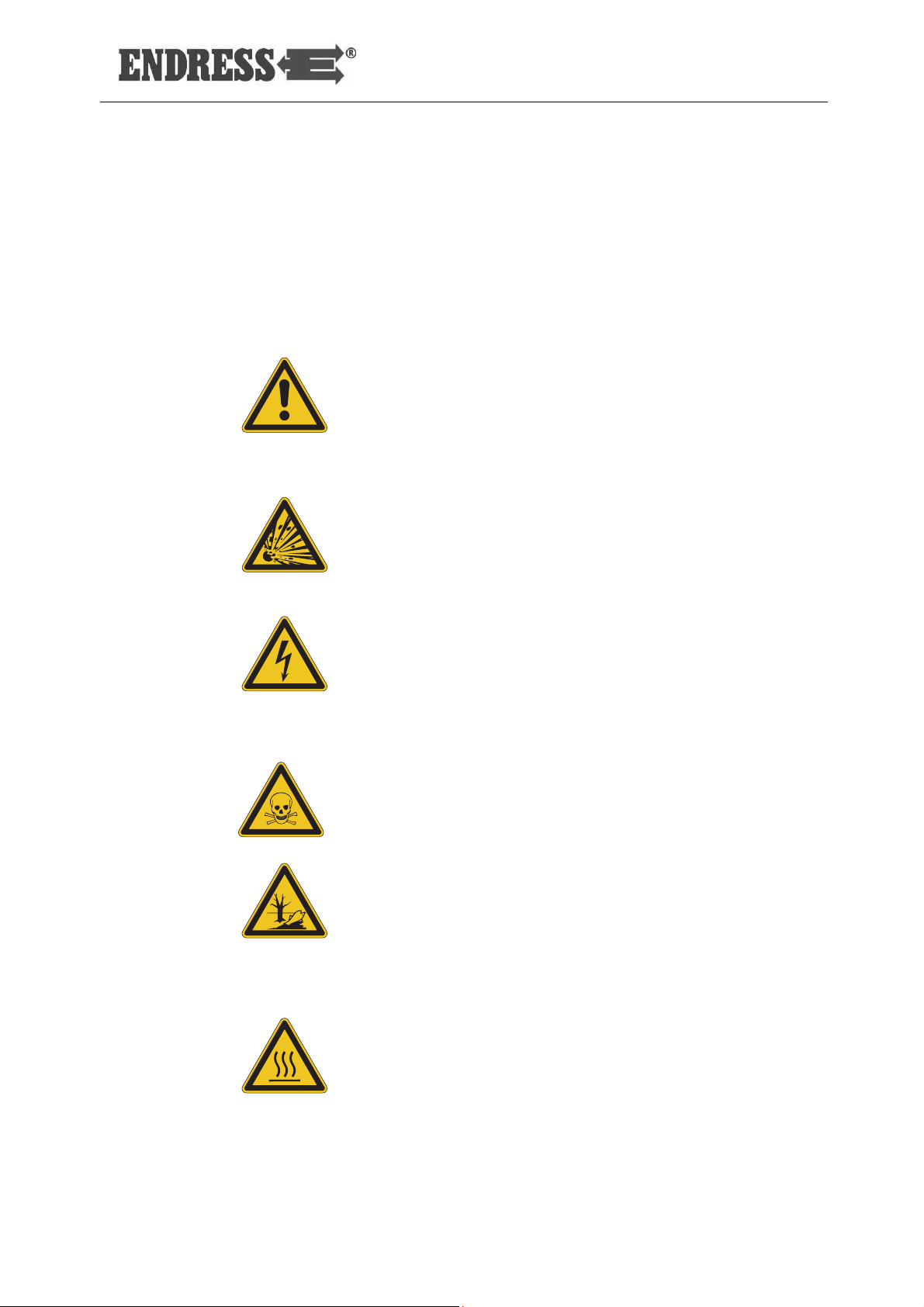
1.2 Safety symbols
General information
The safety symbol illustrates a source of danger. The safety
symbols in the work area of the machine/plant and the entire
technical documentation correspond to the Council Directive
92/58/EEC - Minimum requirements for the provision of safety and/or health signs at work.
General hazard
This warning sign indicates activities where several causes
can lead to risks.
Potentially explosive materials
This warning symbol indicates activities during which there is
an explosive hazard, possibly with lethal consequences.
Dangerous electrical voltage
This warning symbol indicates activities during which there is
the danger of an electric shock, possibly with lethal consequences.
Poisonous substances
This warning symbol indicates activities during which there is
the danger of poisoning, possibly with lethal consequences.
Environmentally damaging substances
This warning sign indicates activities during which the environment could be endangered, possibly with catastrophic
consequences.
Hot surfaces
This warning symbol indicates activities during which there is
the danger of burns, possibly with lasting consequences.
Status at: January 2013
ESE 904 - 1304 DBG DIN
9

General information
Notes
10
ESE 904 - 1304 DBG DIN
Status: at January 2013

2 General Safety Regulations
This section describes the basic safety regulations for operating the generator.
Whoever operates the generator or works with it must read
this chapter and comply with its regulations in practice.
2.1 Important safety warning
ENDRESS generators are designed to operate electrical
equipment with appropriate power output requirements. Other applications can lead to injury to the operating personnel
and to damage to the generator as well as other damage to
equipment.
The majority of injuries and damage to equipment can be
avoided if all instructions given in this manual and all instructions attached to the generator are followed.
The generator must not be modified in any way. This can
lead to an accident occurring and damage to the generator
as well as devices.
WARNING!
Status at: January 2013
ESE 904 - 1304 DBG DIN
11

•
The following actions are not permitted.
Operation in explosion-prone environments
• Operation in fire-prone environments
• Operation in confined areas
• Operation from a vehicle platform that has not been
swung out
• Operation without the necessary safety redundancies
• Operation in existing power supply networks
• Refuelling when hot
• Refuelling during operation
• Spraying with high-pressure cleaners or fire-
extinguishing equipment
• Safety equipment removal
• Incorrect vehicle installation
• Non-compliance with maintenance intervals
• Failure to measure and test for early damage identifica-
tion
• Failure to replace wearing parts
• Incorrectly performed maintenance or repair work
• Defectively performed maintenance or repair work
• Unintended use
2.2 Intended use
The generator produces electricity in place of the power grid,
in order to supply a mobile distribution system.
The generator may only be used outdoors within the indicated voltage, output, and nominal rpm ranges (see model
plate).
You are also permitted to use it on a vehicle extension or
swivelling platform in both extended and swung out states,
providing that the air circulation is uninterrupted on all sides
of the alternator and that the exhaust gases are dispersed
correctly. This is especially relevant as access to the side
with the instrument panel and the side with the exhaust gas
connection must be unrestricted.
The methods that will be used to install the generator on these surfaces of a vehicle require written approval from the
distributor that supplied the generator.
12
ESE 904 - 1304 DBG DIN
Status: at January 2013

The generator may not be connected to other energy distribution systems (e.g. public power supply) or to other energy
generation systems (e.g. other generators).
The generator may not be used in explosion-prone environments.
The generator may not be used in fire-prone environments.
The generator must be operated according to the specifica-
tions in the technical documentation.
Any non-intended use or any activity on the generator not
described in these operating instructions is considered forbidden incorrect use outside the legal limits of the manufacturer's liability.
2.2.1 Residual risks
The points analysed and evaluated before beginning the
design and planning of the
ESE 804 / 1104 / 1304 DBG DIN
generator were the residual risks identified using a risk analysis tool.
Structurally unavoidable residual risks during the entire service life of the
ESE 804 / 1104 / 1304 DBG DIN
generator in-
clude:
• Risk of death
• Risk of injury
• Environmental hazards
• Material damage to the generator
• Material damage to other property
• Limited performance or functionality
You can avoid existing residual risks by observing and following these guidelines:
• the special warning notices on the generator
• the general safety instructions given in these operating
instructions
• the specific warnings given in these operating instruc-
tions
• The specific standing instructions (the relevant opera-
tional conditions) issued by fire-brigades, civil defence
and other relief organisations
Status at: January 2013
ESE 904 - 1304 DBG DIN
13

Risk of death
Risk of injury
Environmental hazards
Material damage to the
Material damage to other
Risk of death to persons at the generator can be caused by:
• Incorrect use
• Inappropriate handling
• Missing protective equipment
• Defective or damaged electrical components
• Fuel vapours
• Engine exhaust
• Too large a distribution network configuration
Risk of injury to persons at the generator can be caused by:
• Inappropriate handling
• Transport
• Hot components
• Recoiling starter rope on the engine
generator
Environmental hazards involving the generator may be
caused by:
• Inappropriate handling
• Operating fluids (fuel, lubricants, engine oil, etc.)
• Exhaust gas emission
• Noise emission
• Fire hazard
• Leaking battery acid
Material damage to the generator can occur through:
• Inappropriate handling
• Overloading
• Overheating
• Too low/high oil level of the engine
• Non-compliance with the operating and maintenance
specifications
• Unsuitable operating fluids
• Unsuitable hoisting gear
14
property
Material damage to other property in the operating range of
the generator can occur through:
• Inappropriate handling
• An over and/or an undervoltage
ESE 904 - 1304 DBG DIN
Status: at January 2013

Limits to performance or
• Incorrect installation in a vehicle
The generator's performance or functionality can be limited
functionality
by:
• Inappropriate handling
• Inappropriate maintenance or repair work
• Unsuitable operating fluids
• An installation altitude greater than 100 metres above
sea level
• An ambient temperature exceeding 25°C
• Too large a distribution network configuration
Status at: January 2013
ESE 904 - 1304 DBG DIN
15

2.3 Operating personnel – qualifications and obligations
Only appropriately authorised personnel may work with or on
the alternator.
The authorised operating personnel must:
• be at least 18 years old.
• be trained in first aid and able to provide it.
• be familiar with the accident prevention regulations and
generator safety instructions and be able to apply them.
• have read the chapter "General Safety Regulations".
• has understand the content of the chapter "General Safe-
ty Regulations".
• be able to use and implement the content of the chapter
"General Safety Regulations" in practice.
• be trained and instructed according to the rules of con-
duct in the event of malfunctions occurring.
• have the physical and mental abilities to carry out his
responsibilities, tasks, and activities on the generator.
• be trained and instructed in his responsibilities, tasks and
activities on the alternator.
• have understood the technical documentation concerning
his responsibilities, tasks and activities on the alternator
and be able to implement these in practice.
2.4 Personal protective equipment
This personal protection equipment must be worn during all
activities at the generator described in these operating instructions:
• hearing protection
• protective gloves
• hard hat
• protective shoes
• fireproof protective clothing (in areas where the danger of
fire is high)
16
ESE 904 - 1304 DBG DIN
Status: at January 2013
Life cycle
Activity
Danger zone
Work area
2.5 Danger zones and work areas
The danger zones work places (work areas) on the generator are determined by the activities to be performed within
the individual life cycles:
Transport in the vehicle Radius of 1.0 m none
by the operating per-
sonnel
Operation Setting up
Operating Radius of 5.0 m
Refuelling Radius of 2.0 m
Service and
maintenance
Cleaning Radius of 1.0 m
Shutting down
Maintenance
Table 2.1: Danger zones and work areas on the generator
Radius of 1.0 m
Status at: January 2013
ESE 904 - 1304 DBG DIN
17
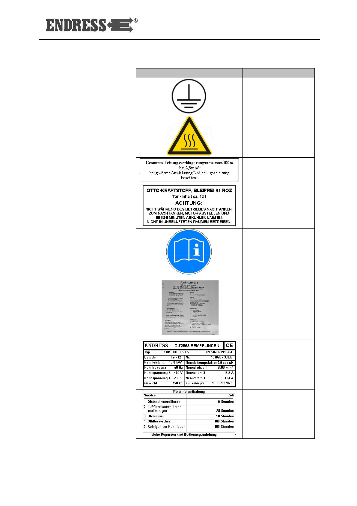
2.6 Labels on the generator
These labels must be attached to the generator and be kept
in a clearly legible condition:
Fig. 2-1: Labels on the generator
1 Potential equalization (earthing for FI) 6 Reference note - "read operating in-
structions"
2 Motor model plate 7 Short operating instructions (interior)/
Reference note regarding short oper-
ating instructions (exterior)
3 Reference note - "hot surface" 8 Model plate
4 Reference note - "cable extension"
9 Reference note - "maintenance"
(under the flap)
5 Reference note - "fuel note" 10 Reference note - "open flame"
11 Reference note - “noise emission”
18
ESE 904 - 1304 DBG DIN
Status: at January 2013
Label
Designation
Potential equalization
(earthing for FI)
Reference note - "hot
surface"
Reference note - "ca-
ble extension"
Reference note - "fuel
note"
Reference note - "read
operating instructions"
Short operating in-
structions (inner side
flap)
Generator model plate
Status at: January 2013
Reference note - "en-
gine
maintenance"
ESE 904 - 1304 DBG DIN
19

Label
Designation
Reference note - "no
naked flames"
Note
Noise emission
Table 2.2: Labels on the generator
2.7 General safety instructions
The generator's construction may not be modified in any
way.
The engine's nominal rpm has been set in the factory and
may not be changed.
All protective covers must be at hand and functional.
All labels on the generator must be in place and in a clearly
legible condition.
The operational reliability and functionality must be checked
before and after each use/operation.
The generator must only be used outdoors with sufficient
ventilation.
Do not use any open flame, light or spark-generating devices
within the generator's danger zone.
20
Protect the alternator against moisture and precipitation
(rain, snow) during operation.
Protect the alternator against dirt and foreign matter during
operation.
The authorised personnel are responsible for the operational
reliability of the alternator.
ESE 904 - 1304 DBG DIN
Status: at January 2013

Transport
Setting up
The authorised personnel are responsible for safeguarding
the alternator against unauthorised operation.
The authorised personnel are obligated to observe the applicable accident prevention regulations.
The authorised personnel are obligated to obey the safety
and work instructions of superiors and/or safety officers.
The authorised personnel are obligated to wear personal
protective equipment.
Only authorised personnel may remain in the generator's
danger zone.
Smoking is absolutely prohibited in the generator's danger
zone.
Open flames and light are prohibited in the generator's danger zone.
Consumption of alcohol, drugs, medications, or other mindaltering substances is prohibited.
The authorised personnel must be familiar with the alternator
components and their function and know how to use them.
The generator may only be transported after it has cooled
down.
The generator may only be transported in a vehicle after being fastened in place correctly (on the transport device).
The generator may only be lifted by the carrying handles
provided.
The generator must be carried by at least as many persons
as there are handles provided.
Status at: January 2013
The generator may only be set up on sufficiently firm ground.
The generator may only be set up on even ground.
ESE 904 - 1304 DBG DIN
21

Generating electricity
Refuelling
Cleaning
The electrical safety must be checked before each start-up.
Do not cover the equipment during use.
Do not obstruct or block the air supply.
Do not use starting aids.
Devices must not be connected during start-up.
Only tested and authorised cables may be used for the pow-
er network.
It is prohibited to establish a connection between existing
neutral conductors, potential equalisation conductors and/or
equipment components (safety-separated circuit).
The entire drawn output must not exceed the maximum nominal output of the generator.
Do not operate the generator without a sound damper.
It is prohibited to operate the generator without air filters and
with an opened air filter cover.
It is prohibited to refill the fuel tank on the generator during
operation.
It is prohibited to refill the fuel tank on the generator when it
is still hot.
Use filling aids for refuelling.
It is prohibited to clean the generator during operation.
It is prohibited to clean the generator when it is still hot.
22
ESE 904 - 1304 DBG DIN
Status: at January 2013

Mai
ntenance and repair
Decommissioning
Do
cumentation
Environmental protection
Operating personnel may only carry out the maintenance or
work
repair work described in these operating instructions.
All other maintenance or repair tasks may only be carried out
by specially trained and authorised specialists.
Always remove the spark plug socket before beginning
maintenance and/or repair work.
The maintenance intervals specified in these operating in-
structions must be observed.
It is prohibited to service the generator during operation.
It is prohibited to service the generator when it is still hot.
The generator should be put out of service if it is not required
for more than 30 days.
Store the generator in a dry and locked room.
Use a petrol additive to prevent resinous residues in the fuel
system.
One copy of these operating instructions must always be
kept in the generator’s manual compartment.
The operating instructions and the maintenance instructions
for the engine (Briggs & Stratton Corporation) are integral
parts of this instruction manual.
The packaging material must be recycled according to the
environmental protection regulations applicable at the place
of use.
The workplace must be protected against contamination by
leaking operating fluids.
Status at: January 2013
Used or leftover fuels and lubricants must be recycled according to the environmental regulations applicable at the
place of use.
ESE 904 - 1304 DBG DIN
23

Notes
24
ESE 904 - 1304 DBG DIN
Status: at January 2013
3 Operating generator ESE 904 - 1304 DBG DIN
The components and functionality of the generator are described in this section.
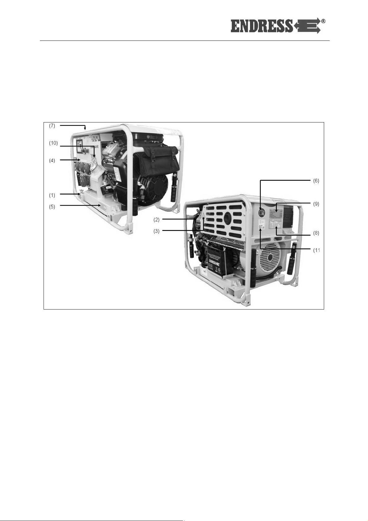
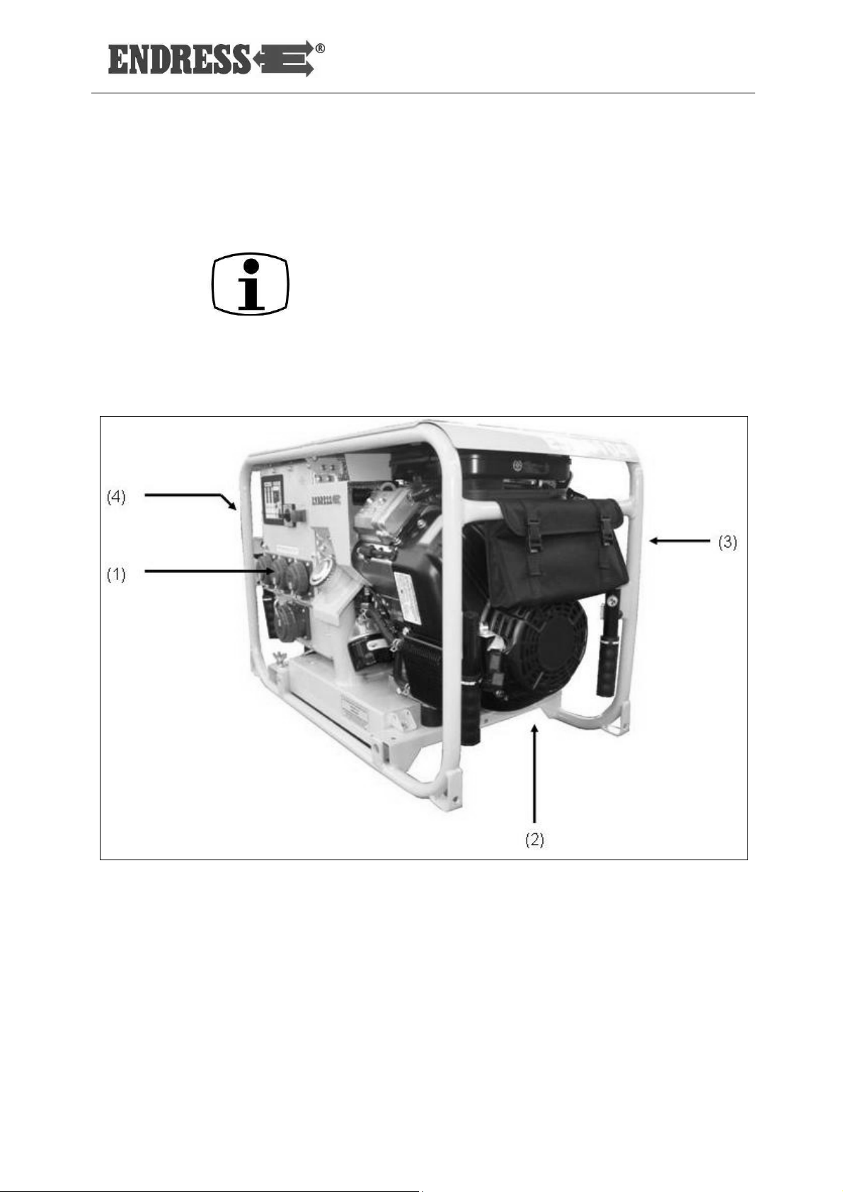
3.1 Components of generator ESE 904 - 1304 DBG DIN
The generator components are distributed on all four sides.
Fig. 3-1: Views of the generator
1 Control side 3 Exhaust gas side
2 Engine side 4 Alternator side
Status at: January 2013
ESE 904 - 1304 DBG DIN
25
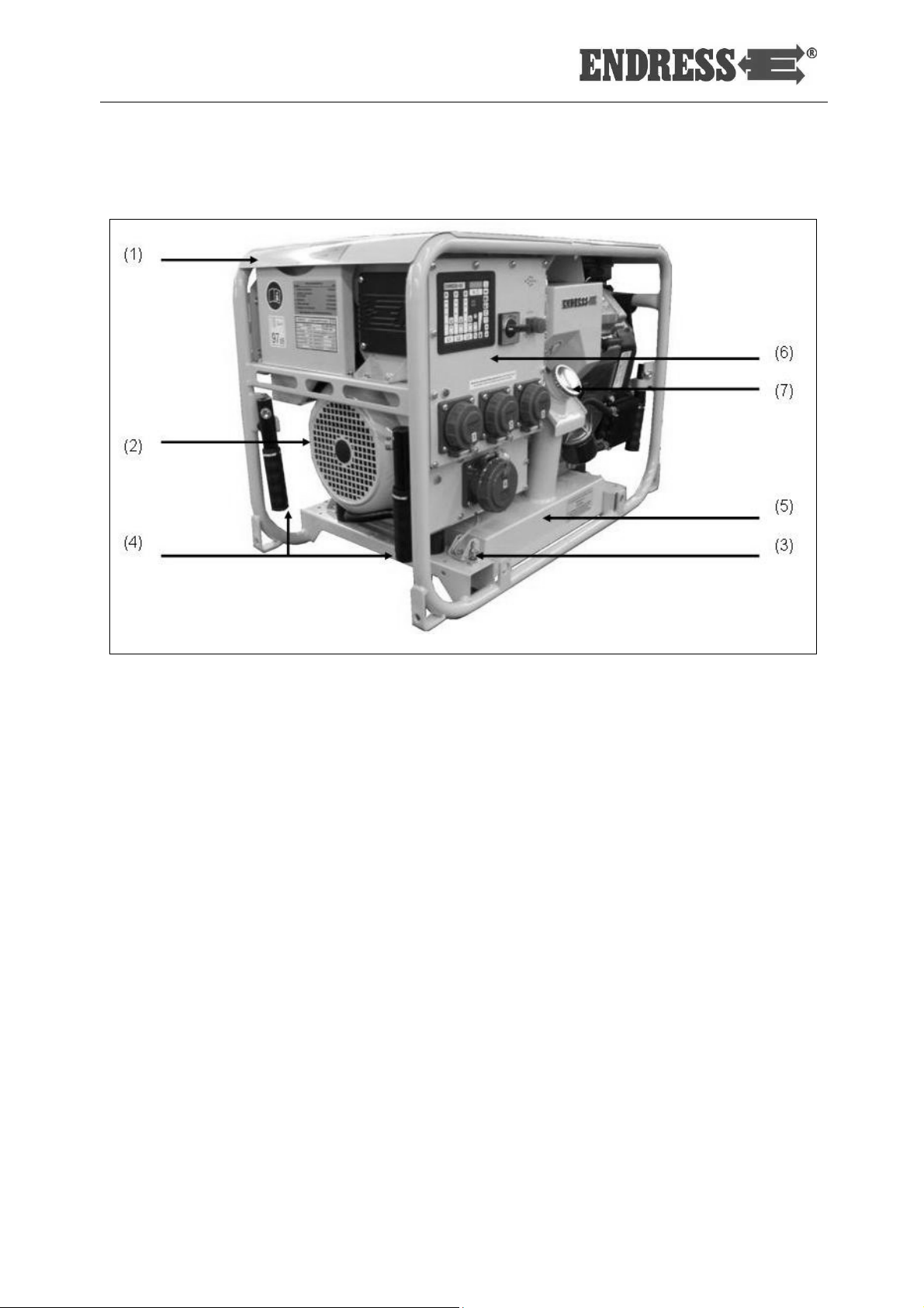
3.1.1 Components of the operating and alternator side
Fig. 3-2: Components of the operating and alternator side
1 Generator lid 5 Tank
2 Generator 6 Electrical compartment
3 Potential equalisation screw (for an
7 Tank cover
optional FI earthing connection)
4 Carrying handle
26
ESE 904 - 1304 DBG DIN
Status: at January 2013
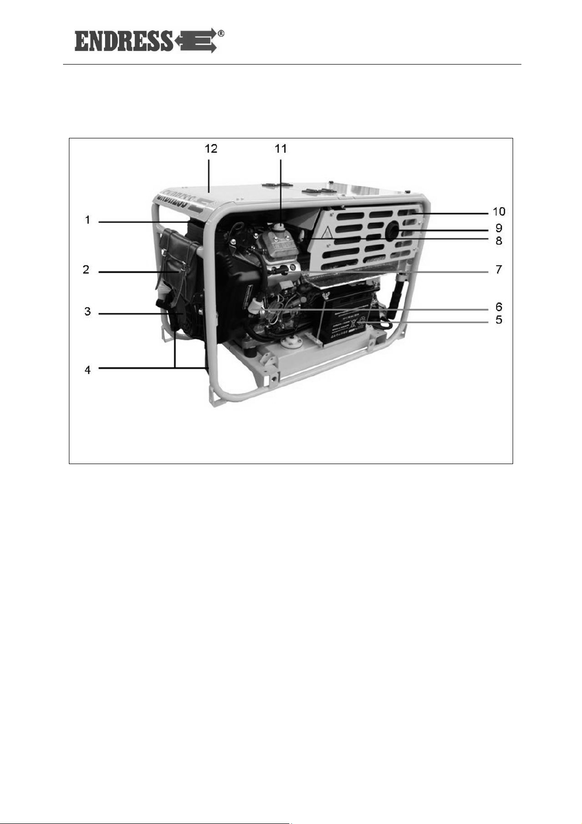
3.1.2 Exhaust and engine side components
Fig. 3-3: Exhaust and engine side components
1 Air filter 7 Spark plug connector
2 Tool pouch 8 Oil dipstick
3 Briggs & Stratton engine 9 Exhaust
4 Carrying handle 10 Exhaust heat shield plate
5 Starter battery 11 Oil filler neck
6 Fuel filter 12 Motor flap
Status at: January 2013
ESE 904 - 1304 DBG DIN
27
 Loading...