

Page 1
TDS-2 Module TDS-6 Unit User Manual
2.5.5r1
EDM05.05-01r1
Page 2

Endace Measurement Systems® Ltd
http://www.endace.com
EDM05.05-01r1 TDS-2 Module TDS-6 Unit User Manual
Leading Network Intelligence
Copyright © 2005.
Published by:
Endace Measurement Systems® Ltd
Building 7
17 Lambie Drive
PO Box 76802
Manukau City 1702
New Zealand
Phone: +64 9 262 7260
Fax: +64 9 262 7261
[email protected]
www.endace.com
International Locations
New Zealand Americas Europe, Middle East & Africa
Endace Technology® Ltd
Level 9
85 Alexandra Street
PO Box 19246
Hamilton 2001
New Zealand
Phone: +64 7 839 0540
Fax: +64 7 839 0543
[email protected]
www.endace.com
All rights reserved. No part of this publication may be reproduced, stored in a retrieval system, or transmitted, in
any form or by any means electronic, mechanical, photocopying, recording, or otherwise, without the prior
written permission of the publisher. Prepared in Hamilton, New Zealand.
Endace USA® Ltd
Suite 220
11495 Sunset Hill Road
Reston
Virginia 20190
United States of America
Phone: ++1 703 382 0155
Fax: ++1 703 382 0155
[email protected]
www.endace.com
Endace Europe® Ltd
Sheraton House
Castle Park
Cambridge CB3 0AX
United Kingdom
Phone: ++44 1223 370 176
Fax: ++44 1223 370 040
[email protected]
www.endace.com
Copyright© All rights reserved
Version 2. 22 September 2005.
Page 3

Endace Measurement Systems® Ltd
http://www.endace.com
EDM05.05-01r1 TDS-2 Module TDS-6 Unit User Manual
USE THIS SPACE FOR NOTES
Copyright© All rights reserved
Version 2. 22 September 2005.
Page 4

Endace Measurement Systems® Ltd
http://www.endace.com
EDM05.05-01r1 TDS-2 Module TDS-6 Unit User Manual
Table of Contents
1.0 OVERVIEW.......................................................................................................................1
1.1 User Manual Purpose......................................................................................................1
1.2 Time Distribution Server System....................................................................................1
2.0 INSTALLING TDS-2 TIME DISTRIBUTION SERVER MODULE..........................3
2.1 TDS-2 Time Distribution Server Module Overview ......................................................3
2.1.1 TDS-2 Time Distribution Server Module Architecture............................................3
2.1.2 TDS-2 Time Distribution Server Module System Requirements.............................5
2.1.3 TDS-2 Time Distribution Server Module Accessories.............................................6
2.2 TDS-2 Time Distribution Server Module Connection to Power Sources.......................6
2.2.1 Connect TDS-2 Module to Electrical Mains Power Source.....................................7
2.2.2 Connect TDS-2 Module to 12V DC Power Source..................................................7
2.3 Connect TDS-2 Module to Code Division Multiple Access Source...............................7
2.4 Connect TDS-2 Module to Global Positioning System Time Signal Source .................8
2.5 Connection to TDS-2 Time Distribution Server Module Applications..........................9
2.5.1 DAG Card Signals Output Connection.....................................................................9
2.5.2 PC Connection to TDS-2 Time Distribution Server Module..................................10
3.0 CONNECTING TDS-6 TIME DISTRIBUTION SERVER EXTENSION UNIT.....11
3.1 Install TDS-6 Time Distribution Server Extension Unit...............................................12
3.2 Connect Additional TDS-6 Time Distribution Server Extension Units........................13
APPENDIX A – TDS-2 MODULE, CONNECTOR SPECIFICATIONS........................15
RS422 RJ45 Timing DB2J to DB9 Signal Output..............................................................15
RS232 DB9 CDMA Input...................................................................................................16
RS422 DB9 GPS Input........................................................................................................16
RS232 Host PC Connection................................................................................................16
RS422 Chain Output...........................................................................................................17
DB25 to DB9 GPS Adapter Plug........................................................................................17
APPENDIX B – TDS-6 EXTENSION UNIT, CONNECTOR SPECIFICATIONS .......18
RS422 RJ45 Timing Signal Output.....................................................................................18
RS422 Chain Connection....................................................................................................19
Copyright© All rights reserved
i
Version 2. 22 September 2005.
Page 5

Endace Measurement Systems® Ltd
http://www.endace.com
EDM05.05-01r1 TDS-2 Module TDS-6 Unit User Manual
USE THIS SPACE FOR NOTES
Copyright© All rights reserved
ii
Version 2. 22 September 2005.
Page 6

Endace Measurement Systems® Ltd
http://www.endace.com
EDM05.05-01r1 TDS-2 Module TDS-6 Unit User Manual
1.0 OVERVIEW
Introduction
The Endace time distribution servers provide accurate synchronized
timing signals to DAG cards for packet timestamping through use of
global positioning system time signals.
The process involves a global positioning system [GPS] or code division
multiple access system [CDMA], time distribution server components, and
DAG cards.
In this chapter
This chapter covers the following sections of information.
• User Manual Purpose
• Time Distribution Server System
1.1 User Manual Purpose
Description
The purpose of this TDS 2 installation manual is to identify and explain:
• Installing TDS-2 Time Distribution Server Module
• Connecting TDS-6 Time Distribution Server Extension Unit
• Appendix A – TDS-2 Module, Connector Specifications
• Appendix B – TDS-6 Extension Unit, Connector Specifications
1.2 Time Distribution Server System
Description
The time distribution server system involves TDS-2 Time Distribution
Server modules [TDS-2 module] receiving time signals either directly
from a GPS receiver or a CDMA time receiver.
Accurate time synchronization information constantly transmitted by GPS
satellites orbiting Earth is collated on the ground by GPS receivers.
Receiver units can be mounted on building exteriors or elsewhere with an
unobstructed sky view. A GPS receiver unit is connected to a TDS-2
module by fitting a DB25 cable to a DB25-toDB9 adapter on the module.
In many situations it is not possible or economic to run cable to a GPS
receiving unit mounted externally on buildings. In this case, a CDMA
cellular telephone network is used, where available. A CDMA system
base station has a GPS receiver to collate the accurate timing transmitted
by satellites.
Timing information is retransmitted from CDMA base stations to all
CDMA receivers. Being of a lower frequency these transmissions can
often be received within buildings without an external antenna.
Continued on next page
Copyright© All rights reserved
1
Version 2. 22 September 2005.
Page 7

Endace Measurement Systems® Ltd
http://www.endace.com
EDM05.05-01r1 TDS-2 Module TDS-6 Unit User Manual
1.2 Time Distribution Server System, continued
Description, continued
Figure
Time Distribution Server TDS-2 modules and TDS 6 units are connected
by cable to a DAG card timing connector. The precise time reference
signals are fed from receivers to TDS-2 Time Distribution Servers, which
relay them to DAG cards, PC’s or TDS 6 expander units.
The capacity of a TDS-2 module can be expanded six outputs at a time by
chaining up to four TDS 6 expansion units without compromising timing
accuracy.
The power source for TDS-2 modules is 12V DC through an adapter
connected to an electrical mains source, or directly from a 12V DC source.
Diagram 1-1 shows the typical time server distribution system.
Copyright© All rights reserved
Figure 1-1. Typical Time Server Distribution System.
2
Version 2. 22 September 2005.
Page 8

Endace Measurement Systems® Ltd
http://www.endace.com
EDM05.05-01r1 TDS-2 Module TDS-6 Unit User Manual
2.0 INSTALLING TDS-2 TIME DISTRIBUTION SERVER MODULE
Introduction
Installation of the TDS-2 module involves connecting to an AC mains
power source or 12V DC source and then connecting to a suitable timing
single source. A 2.5mm plug fits to a 12V DC power source jack marked
on the TDS-2 module rear panel.
In this chapter
This chapter covers the following sections of information.
• TDS-2 Time Distribution Server Module Overview
• TDS-2 Time Distribution Server Module Connection to Power
Sources
• Connect TDS-2 Module to Code Division Multiple Access Source
• Connect TDS-2 Module to Global Positioning System Time Signal
Source
• Connection to TDS-2 Time Distribution Server Module
Applications
2.1 TDS-2 Time Distribution Server Module Overview
Description
In this section
The TDS-2 Time Distribution Server module has a distinct architecture
relative to its purpose with specific system requirements. The module also
has accessories available that expand its function.
This section covers the following topics of information.
• Connect TDS-2 Module to Electrical Mains Power Source
• Connect TDS-2 Module to 12V DC Power Source
• TDS-2 Time Distribution Server Module Accessories
2.1.1 TDS-2 Time Distribution Server Module Architecture
Description
Copyright© All rights reserved
The TDS-2 module is fitted with cable ports and connectors to receive
precise time signal inputs, replicate them, and distribute directly to one or
two DAG cards. The TDS-2 architecture features include:
• GPS input from Trimble Acutime 2000 GPS time receiver, Type
RS422.
• CDMA input from Endrun Technologies Praecis Ct CDMA time
receiver, Type RS232.
• Connection to a PC to monitor timing information and provide
network time services via NTP.
• Two outputs enabling connection of up to two DAG cards.
• Chain Out - enables daisy-chaining of TDS-6 modules through
connection to a single external time reference.
• Status LED indicators
• Accepts 12V DC power from an external source.
• Supplies DC power to GPS receiver.
Continued on next page
3
Version 2. 22 September 2005.
Page 9
Endace Measurement Systems® Ltd
http://www.endace.com
EDM05.05-01r1 TDS-2 Module TDS-6 Unit User Manual
2.1.1 TDS-2 Time Distribution Server Module Architecture, continued
CAUTION
TDS-2 module
face-plate
Figure
The standard Ethernet cables and patch equipment do not carry Ethernet
signals and must never be connected to Ethernet equipment such as hubs,
routers, or NICs.
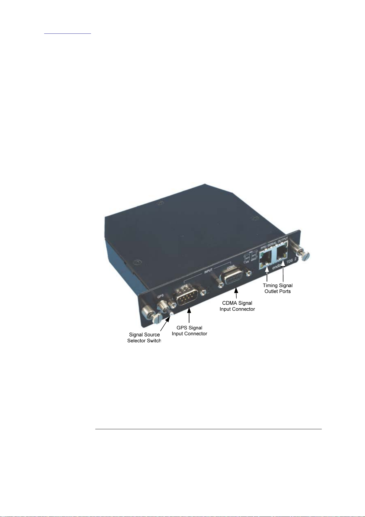
The TDS-2 module face-plate is fitted with:
• Signal source selector switch
• CDMA signal input connector
• GPS signal input connector
• LED’s for power source, PPS and SERIAL signal status
• Timing signal outlet ports
Figure 2-1 shows the TDS-2 module face-plate architecture.
The timing signal outputs are provided through RJ45 connectors, and may
be connected to DAG cards with standard Ethernet cables and patch
equipment.
When DC power is provided to the module, the power LEDs display.
Copyright© All rights reserved
Figure 2-1. TDS-2 Module Face-plate Architecture.
Continued on next page
4
Version 2. 22 September 2005.
Page 10
Endace Measurement Systems® Ltd
http://www.endace.com
EDM05.05-01r1 TDS-2 Module TDS-6 Unit User Manual
2.1.1 TDS-2 Time Distribution Server Module Architecture, continued
TDS-2 backplate
Figure
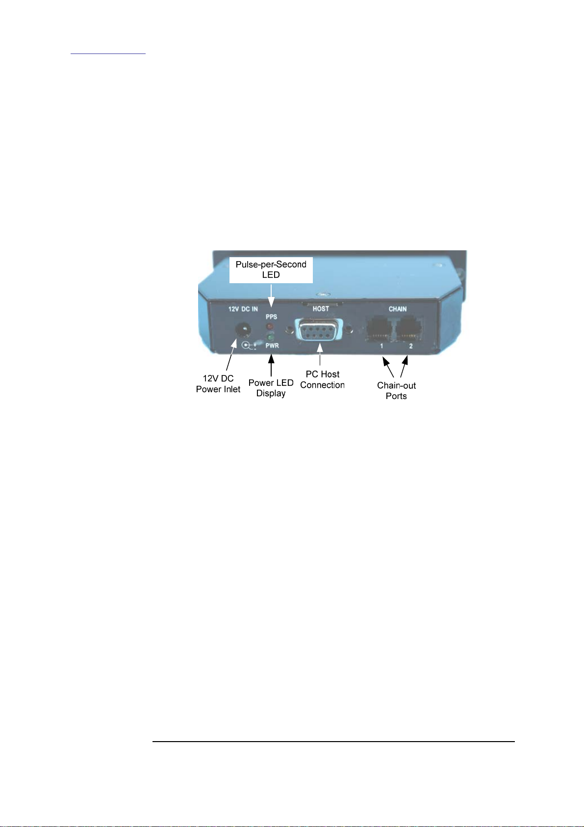
The TDS-2 module rear-plate contains:
• 12V DC power inlet
• Power status LED
• PPS status LED
• Host connector for connection to a PC
• Chain out port for optional connection to Endace TDS-6 signal
expansion units
Figure 2-2 shows the TDS-2 module rear-plate architecture.
Figure 2-2. TDS-2 Module Rear-plate Architecture.
TDS-6 module
When additional time synchronization outputs are required, the capacity of
a TDS-2 module is expanded six outputs at a time without compromising
timing accuracy by attaching up to four Endace TDS6 units.
One TDS-2 module with the maximum number of TDS-6 expansion
modules provides 24 time synchronization outputs derived from a single
external time standard. The TDS-6 unit outputs are connected to up to 24
DAG cards using conventional Ethernet style patch cables.
2.1.2 TDS-2 Time Distribution Server Module System Requirements
Description
The TDS-2 Time Distribution Server module minimum operating system
requirements are:
• 12V DC power to rear panel, typical power consumption is 2 watts
• An external time reference source:
o GPS input from Trimble Acutime 2000 GPS time receiver,
Type RS422
o CDMA input from Endrun Technologies Praecis Ct CDMA
time receiver, Type RS232
• Standard Ethernet type RJ45-RJ45 cabling for connecting to DAG
cards
Continued on next page
Copyright© All rights reserved
5
Version 2. 22 September 2005.
Page 11

Endace Measurement Systems® Ltd
http://www.endace.com
EDM05.05-01r1 TDS-2 Module TDS-6 Unit User Manual
2.1.2 TDS-2 Time Distribution Server Module System Requirements,
continued
Timing signal
ports
The timing signal ports use RJ45 connectors. Connections to DAG cards
are made with normal Ethernet style Cat-5/6 cables and infrastructure,
using straight-through type only.
Trimble
Acutime 2000
GPS Kit
The Trimble Acutime 2000 GPS receiver can be purchased as part of the
Acutime 2000 Synchronisation Kit, including integrated antenna/receiver,
100 foot cable, power supply, and signal converter, Trimble part number
40986-00. Only the antenna/receiver and cable are needed for use with the
TDS-2.
The antenna/receiver can be purchased separately [39091-00], with
matching cables in 50, 100, 200, and 400 foot lengths [23098, 23099,
24017, 24260].
Praecis Ct
CDMA time
receiver
The Praecis Ct CDMA time receiver is available directly from Endrun
Technologies Ltd. There must be a CDMA network available with good
signal at the intended installation site. This may be checked with a CDMA
cellular phone in digital mode.
CAUTION
The TDS-2 must never be connected directly to active Ethernet
equipment.
2.1.3 TDS-2 Time Distribution Server Module Accessories
Description
The accessories included with the TDS-2 Time Distribution Server
include:
• One DB9-to-DB25 Adapter, enabling connection of Trimble
Acutime 2000 to TDS-2 module
NOTE: Only the adapter supplied is used for this connection.
Optional extras
• 12V DC power adapter
• 19" rack-mount kit available - 1U (1.75") standard size
• Endace TDS-6 Time Distribution Expansion Unit
2.2 TDS-2 Time Distribution Server Module Connection to Power Sources
Introduction
In this section
The TDS-2 module can function with alternative power sources. The
module can be connected either to an electrical mains power source using
an AC-to-DC adapter, or directly to a DC power source.
This section covers the following topics of information.
Copyright© All rights reserved
• Connect TDS-2 Module to Electrical Mains Power Source
• Connect TDS-2 Module to 12V DC Power Source
6
Version 2. 22 September 2005.
Page 12
Endace Measurement Systems® Ltd
http://www.endace.com
EDM05.05-01r1 TDS-2 Module TDS-6 Unit User Manual
2.2.1 Connect TDS-2 Module to Electrical Mains Power Source
Description
The TDS-2 module accepts electrical mains power using an optional
AC/DC adapter.
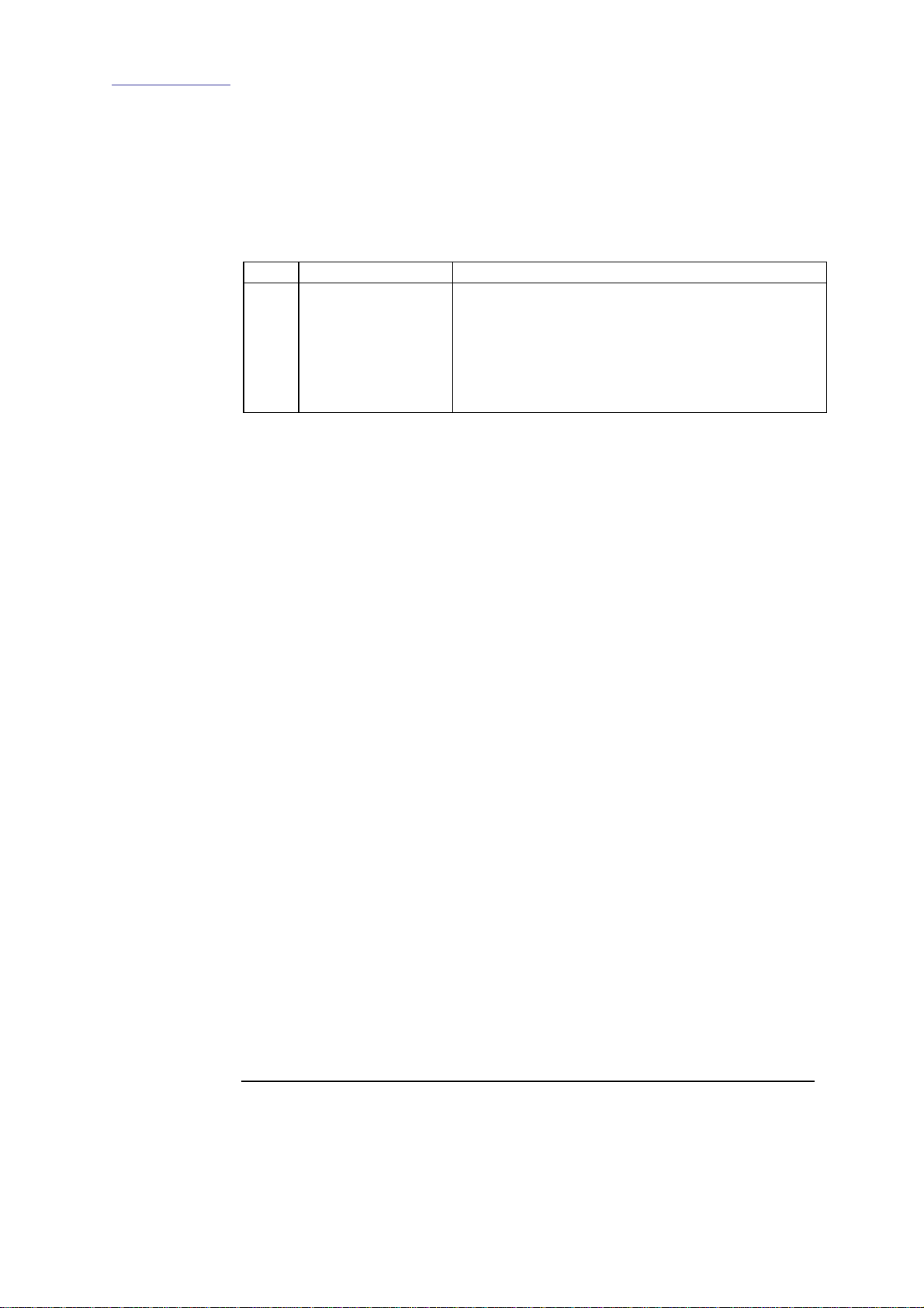
Procedure
Follow this step to connect the TDS-2 module to mains power source.
No. Step Key Points
1. Connect to mains
power.
Connect TR36A12 AC/DC adapter to a mains
power source via a suitable IEC 32/C8 cable.
Connect the TR36A12 2.5mm DC plug to the
receptable on TDS-2 module back-plate.
2.2.2 Connect TDS-2 Module to 12V DC Power Source
Description
Procedure
Step 1 Connect DC Power Source
For connection of the TDS-2 module directly to a 12V DC power source
the polarity is indicated on the rear face of the module, directly below the
12V DC power receptable.
The TDS-2 module has an internal reverse polarity protection diode but no
fuse protection.
Follow this step to connect the TDS-2 unit to the 12 volt DC power
source.
Run a suitable lead from the 12V power source to TDS-2 module and fit
a 2.5mm DC coaxial plug.
CAUTION: If the module is being fitted to an unprotected power source,
an external fuse of 2 amps value is required.
2.3 Connect TDS-2 Module to Code Division Multiple Access Source
Description
An RJ45 cable is used to connect a TDS-2 module to a CDMA source via
an adapter supplied with the CDMA receiver.
The module signal source selection switch is set to CDMA and the LED
flashes indicate processes are occurring in relation to timing signal and
SERIAL packet activity.
Continued on next page
Copyright© All rights reserved
7
Version 2. 22 September 2005.
Page 13

Endace Measurement Systems® Ltd
http://www.endace.com
EDM05.05-01r1 TDS-2 Module TDS-6 Unit User Manual
2.3 Connect TDS-2 Module to Code Division Multiple Access
Source
, continued
Procedure
Follow these steps to connect the code division multiple access source.
Step 1 Connect CDMA Receiver
Connect RJ45 cable from CDMA receiver to DB9-to-RJ45 adapter supplied
with CDMA kit.
Set signal source selection switch to CDMA.
CAUTION: Only use the DB9-to-RJ45 adapter supplied with CDMA
receiver otherwise damage will occur to the equipment.
Step 2
Check Timing Signal.
When CDMA unit locks onto the network, the CDMA receiver’s LEDs
activate, with the PPS LED flashing once per second indicating the timing
signal is being received.
The PPS LED on the TDS-2 front faceplate should now be flashing.
2.4 Connect TDS-2 Module to Global Positioning System Time Signal Source
Description
Procedure
Step 1 Connect GPS Receiver
The TDS-2 module is connected by cable to the GPS receiver signal
source and the signal source selection switch is set to GPS.
After 5-15 minutes the GPS antenna locks onto the GPS satellites and the
activity LEDs start flashing.
Follow these steps to connect TDS-2 module to global positioning time
signal source.
Connect GPS receiver to the TDS-2 module GPS signal input using the
cable and Endace supplied adapter.
The TDS-2 automatically supplies DC power through this cable to the
antenna.
Continued on next page
Copyright© All rights reserved
8
Version 2. 22 September 2005.
Page 14

Endace Measurement Systems® Ltd
http://www.endace.com
EDM05.05-01r1 TDS-2 Module TDS-6 Unit User Manual
2.4 Connect TDS-2 Module to Global Positioning System
Time Signal Source
Procedure (continued)
Step 2 Set Module to Receive GPS Signal
Set input signal selection switch to GPS position. This sets the GPS as the
active signal source.
NOTE: The TDS-2 module LEDs will indicate the GPS receiver status after
a 5 to 15 minute delay during which the system correlates orbiting signal
sources.
Step 3 Check Module Operating Status
The PPS LED flashes once per second indicating the timing signal is
present.
The SERIAL LED flashes to indicate time information packets are present.
Step 4 Change GPS Settings
, continued
If a change is required to GPS settings, connect a PC directly to GPS
receiver via the Trimble Synchronization Interface Module.
2.5 Connection to TDS-2 Time Distribution Server Module Applications
Introduction
In this chapter
A PC can be connected to the ‘Host’ DB-9 connector using a ‘straight
through’ or ‘modem’ SERIAL cable.
This connection can be used to provide a reference clock to the PC in
order to operate a NTP server.
This chapter covers the following sections of information.
• DAG Card Signals Output Connection
• PC Connection to TDS-2 Time Distribution Server Module
2.5.1 DAG Card Signals Output Connection
Description
Once the TDS-2 module is fully functioning, a DAG card can be
connected via a standard Ethernet patch cable connected to the timing
signal output ports.
Copyright© All rights reserved
9
Version 2. 22 September 2005.
Page 15

Endace Measurement Systems® Ltd
http://www.endace.com
EDM05.05-01r1 TDS-2 Module TDS-6 Unit User Manual
2.5.2 PC Connection to TDS-2 Time Distribution Server Module
Description
Procedure
Step 1 Connect TDS-2 Module to PC
Step 2 Check Signal Source Switch
Once the TDS-2 module is fully functioning, a PC can be connected via
the module’s host connection.
The PPS signal and SERIAL data packet is then received by the PC. If the
timing signal is being generated by a CDMA receiver, the packet can be
read on a PC via a standard terminal package.
If the timing signal is being generated by a GPS, a decoding software
program, such as supplied with the Trimble Acutime 2000 Kit, needs to be
installed for on-screen display of the packet-read.
This connection can also be used to provide a reference clock to the PC in
order to operate a NTP server.
Follow these steps to connect a PC directly to a TDS-2 module.
Use a straight-through DB9M-to-DB9F SERIAL cable.
Ensure TDS-2 module switch is set to correct timing signal source position.
Copyright© All rights reserved
10
Version 2. 22 September 2005.
Page 16
Endace Measurement Systems® Ltd
http://www.endace.com
EDM05.05-01r1 TDS-2 Module TDS-6 Unit User Manual
3.0 CONNECTING TDS-6 TIME DISTRIBUTION SERVER EXTENSION UNIT
Introduction
Figure
Connecting a TDS-2 module to a TDS-6 Time Distribution Server unit
expands distribution of global time synchronization signals to multiple
destinations.
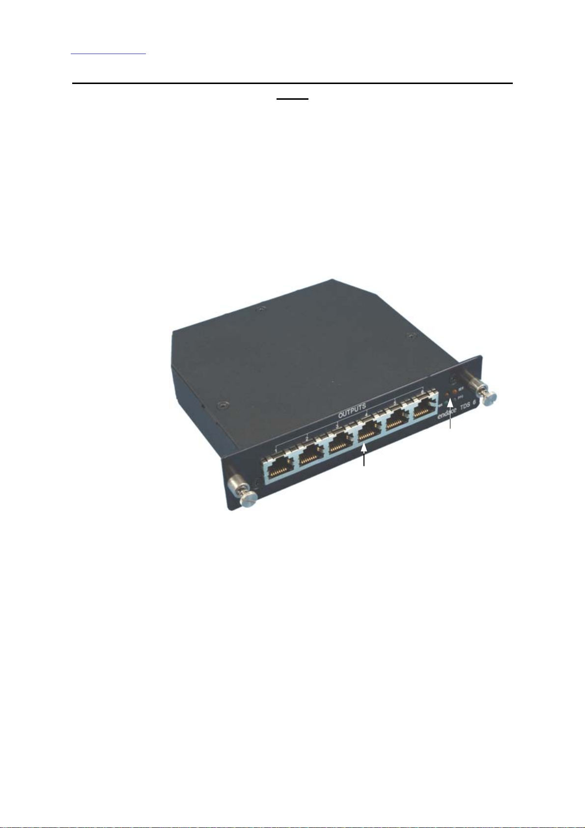
The TDS-6 expansion unit provides 6 time signal synchronization outputs
derived from a single TDS-2 module connection.
Each time-synchronization output is independently driven with power
derived from a TDS-2 module through the chain cables.
Figure 3-1 shows the TDS-6 Time Distribution Server extension unit.
In this chapter
Status LED’s
Time Signal
Synchronization Outputs
Figure 3-1. TDS-6 Time Distribution Server Extension Unit.
This chapter covers the following sections of information.
• DAG Card Signals Output Connection
• Connect Additional TDS-6 Time Distribution Server Extension
Units
Copyright© All rights reserved
11
Version 2. 22 September 2005.
Page 17
Endace Measurement Systems® Ltd
http://www.endace.com
EDM05.05-01r1 TDS-2 Module TDS-6 Unit User Manual
3.1 Install TDS-6 Time Distribution Server Extension Unit
Description
Figure
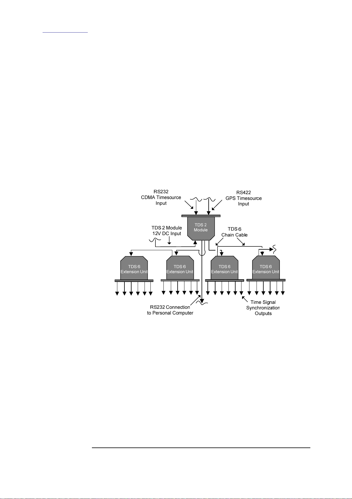
Installing a TDS-6 unit involves connecting to an RS422 GPS time source
output from a TDS-2 module. The synchronized time signals travel from
the TDS-2 CHAIN port to TDS-6 extension unit through chain cables.
The signals travel to DAG cards through the TDS-6 unit synchronization
outputs.
A TDS-6 Time Distribution Server extension unit is firmly fixed in a
position where cables are readily accessed without obstruction.
Connecting the TDS-6 unit involves inserting the supplied chain cable to
the TDS-6 CHAIN 1 port and inserting the other end into a vacant TDS-2
module CHAIN port.
Figure 3-2 shows the typical TDS-2 module and TDS-6 unit connection
configuration.
Procedure
Follow these steps to install a TDS-6 Time Distribution Server extension
unit to a TDS-2 module.
Step 1 Position TDS-6 Unit
Fix unit firmly in a position where the chain cable reaches to TDS-2 module
CHAIN outlet port without strain or obstruction.
Check cable run to DAG card to ensure sufficient length between unit and
card location.
Copyright© All rights reserved
Figure 3-2. Typical TDS-2 Module and TDS-6 Unit Connection
Configuration.
Continued on next page
12
Version 2. 22 September 2005.
Page 18

Endace Measurement Systems® Ltd
http://www.endace.com
EDM05.05-01r1 TDS-2 Module TDS-6 Unit User Manual
3.1 Install TDS-6 Time Distribution Server Extension Unit, continued
Procedure, continued
Step 2
Fit chain cable.
Plug chain cable into TDS-6 CHAIN 1 inlet port.
Plug the other end of cable into a vacant TDS-2 module CHAIN output.
Step 3 Connect TDS-6 Unit to DAG Card
On front plate of TDS-6 unit, plug cable into a vacant outlet and insert other
end into DAG card.
Step 4 Inspect TDS Unit Operating Status
On the front of TDS-6 unit, check power LED is ON and status LED’s are
flashing for:
• PPS
• SERIAL
On the back of the unit, check PPS LED is flashing.
NOTE: If the LED’s are not flashing check the TDS-2 module is powered,
and check connections. In event of a function failure, contact Endace
support; [email protected]
3.2 Connect Additional TDS-6 Time Distribution Server Extension Units
Description
A number of TDS-6 units can be coupled together like a daisy-chain to
enable extension of time-synchronization output to more DAG cards or
PC’s.
If the two TDS-2 module chain outputs are in use, with two TDS-6 units
already being connected, additional TDS-6 units can be chained to the first
TDS-6 units.
Copyright© All rights reserved
13
Continued on next page
Version 2. 22 September 2005.
Page 19

Endace Measurement Systems® Ltd
http://www.endace.com
EDM05.05-01r1 TDS-2 Module TDS-6 Unit User Manual
3.2 Connect Additional TDS-6 Time Distribution Server Extension
Units
, continued
Procedure
Step 1. Position TDS-6 unit
Step 2. Chain to Functioning TDS-6 Unit
Step 3. Inspect TDS-6 unit operating status
Follow these steps to chain additional TDS-6 Time Distribution Server
extension units.
Fix unit firmly in a position where chain cable will reach a functioning TDS6 unit CHAIN outlet without strain or obstruction.
Check cable run to intended destination to ensure sufficient length to
chained TDS-6 unit.
Connect supplied cable to functioning TDS-6 unit CHAIN 2 outlet and
connect other end to CHAIN 1 input on the new TDS-6 unit.
On front of new unit, check the power LED is ON and status LED’s are
flashing for:
• PPS
• SERIAL
On the back of the unit, check the PPS LED is flashing constantly.
NOTE: If the LED’s are not flashing check the TDS-2 module is powered
and operating, or check connections. In the event of a function failure
contact Endace support; [email protected]
Copyright© All rights reserved
14
Version 2. 22 September 2005.
Page 20
Endace Measurement Systems® Ltd
http://www.endace.com
EDM05.05-01r1 TDS-2 Module TDS-6 Unit User Manual
APPENDIX A – TDS-2 MODULE, CONNECTOR SPECIFICATIONS
Introduction
The specifications for the TDS-2 module connector pin-outs include:
• RS422 RJ45 Timing DB2J to DB9 Signal Output
• RS232 DB9 CDMA Input
• RS422 DB9 GPS Input
• RS232 Host PC Connection
• RS422 RJ45 Timing Signal Output
• DB25 to DB9 GPS Adapter
RS422 RJ45 Timing DB2J to DB9 Signal Output
Description
Figure
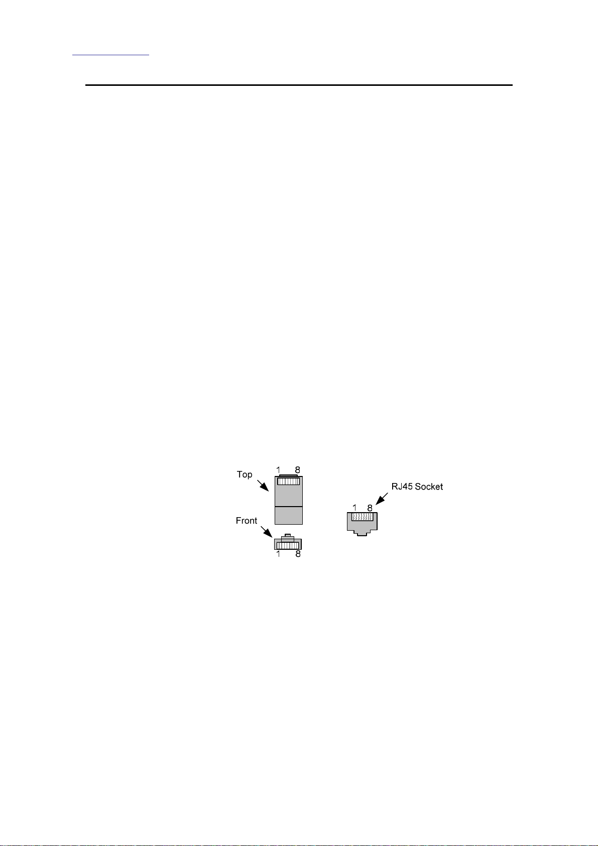
The TDS-2 module has two RJ45 socket outputs for connecting to DAG
card RS422 synchronisation input port. The socket consists of 8 pins.
The pin-out configuration is shown below.
1: NC
2: NC
3: PPS Out+
4: SERIAL Out+
5: SERIAL Out6: PPS Out7: NC
8: NC
Figure 5-1 shows the DAG RJ45 plug and socket pin-out configuration..
Copyright© All rights reserved
Figure 5-1. DAG RS45 Plug and Socket Pin-out Configuration.
15
Version 2. 22 September 2005.
Page 21

Endace Measurement Systems® Ltd
http://www.endace.com
RS232 DB9 CDMA Input
EDM05.05-01r1 TDS-2 Module TDS-6 Unit User Manual
Description
The TDS-2 module has one DB9 input for connecting the Endrun
Technologies Praecis Ct CDMA time receiver using standard Ethernet
type cables. The pin-out configuration is shown below.
1: PPS In
2: SERIAL In
3: Ext-SERIAL out
4: NC
5: Ground
6: NC
7: CTS Out
8: NC
9: NC
NOTE: “In” and “Out” destinations relate to TDS modules and TDS-6
units.
RS422 DB9 GPS Input
Description
The one DB9 input is used for connecting a Trimble Acutime global
positioning system receiver. The pin-out configuration is shown below.
1: Event Out + [optional]
2: Event Out – [optional]
3: PPS In +
4: SERIAL In +
5: SERIAL In 6: PPS In 7: N/C
8: Ground
9: Power Out [12V DC]
RS232 Host PC Connection
Description
A standard female DB9 on the TDS-2 module enables connection to a host
PC. The pin-out configuration is shown below.
1. PPS Out
2. SERIAL Out
3. Ext-SERIAL In
4. CDMA port, pin 4
5. GND
6. CDMA port, pin 6
7. CTS IN
8. CDMA port, pin 8
9. CDMA port, pin 9
Copyright© All rights reserved
16
Version 2. 22 September 2005.
Page 22
Endace Measurement Systems® Ltd
http://www.endace.com
RS422 Chain Output
EDM05.05-01r1 TDS-2 Module TDS-6 Unit User Manual
Description
Figure
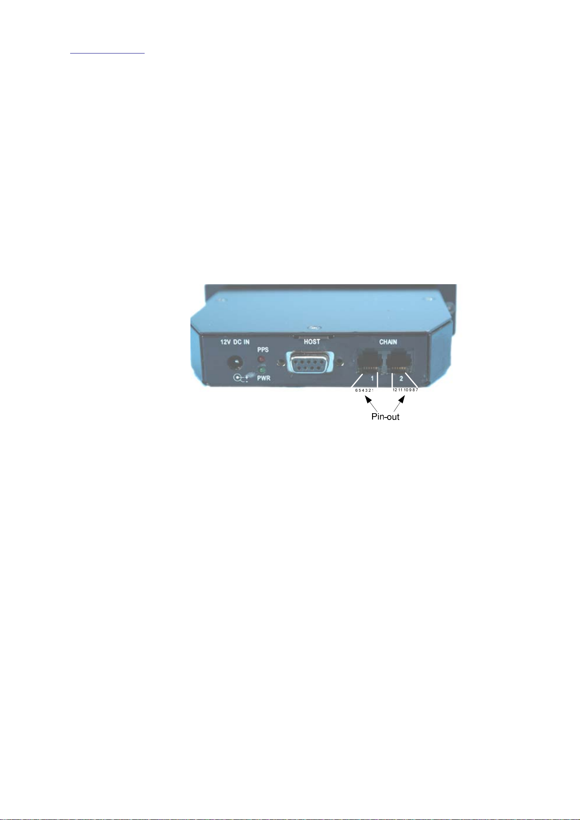
A two-port six-position, six-contact modular jack provides direct
connection for up to two TDS-6 modules. The pin-out configuration is
shown below.
1: GND
2: PPS Out +
3: SERIAL Out +
4: SERIAL Out 5: PPS Out 6: Power Out [12V DC]
7: GND
8: PPS Out +
9: SERIAL Out +
10: SERIAL Out 11: PPS Out 12: Power Out [12V DC]
Figure 5-2 shows the TDS-2 module chain output pin-out configuration.
Figure 5-2. TDS-2 Module Chain Output Pin-out Configuration.
DB25 to DB9 GPS Adapter Plug
Description
The Endace supplied DB25 to DB9 GPS adaptor plug housed in a single
body enables connection of the Trimble Acutime receiver to a TDS-2
module.
DB9 Male Signal Name DB25 Female
Shell Shield Drain Shell
1: Event + 12
2: Event - 24
3: PPS+ 21
4: SERIAL+ 22
5: SERIAL- 10
6: PPS- 9
7. N/C -
8. GND 7
9. 12VGPS 1
Copyright© All rights reserved
17
Version 2. 22 September 2005.
Page 23
Endace Measurement Systems® Ltd
http://www.endace.com
APPENDIX B – TDS-6 EXTENSION UNIT, CONNECTOR
SPECIFICATIONS
RS422 RJ45 Timing Signal Output
EDM05.05-01r1 TDS-2 Module TDS-6 Unit User Manual
Description
Figure
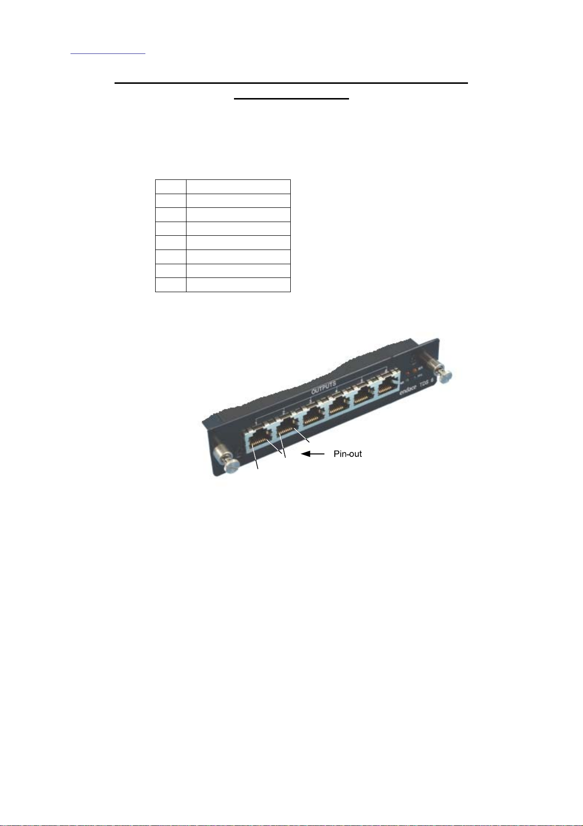
There are six RS422 ports on the TDS-6 unit on a RJ45 modular jack that
provides synchronized timing signals to DAG card RSS422 input ports.
1. N/C
2. N/C
3. PPS Out +
4. SERIAL Out +
5. SERIAL Out -
6. PPS Out -
7. N/C
8. N/C
Figure 5-3 shows the TDS-6 timing signal outputs pin-out configuration.
1
2
3
4
5
6
7
1
8
2
3
4
5
6
7
8
Figure 5-3. TDS-6 Timing Signal Outputs Pin-out Configuration.
Copyright© All rights reserved
18
Version 2. 22 September 2005.
Page 24
Endace Measurement Systems® Ltd
http://www.endace.com
RS422 Chain Connection
EDM05.05-01r1 TDS-2 Module TDS-6 Unit User Manual
Description
Figure
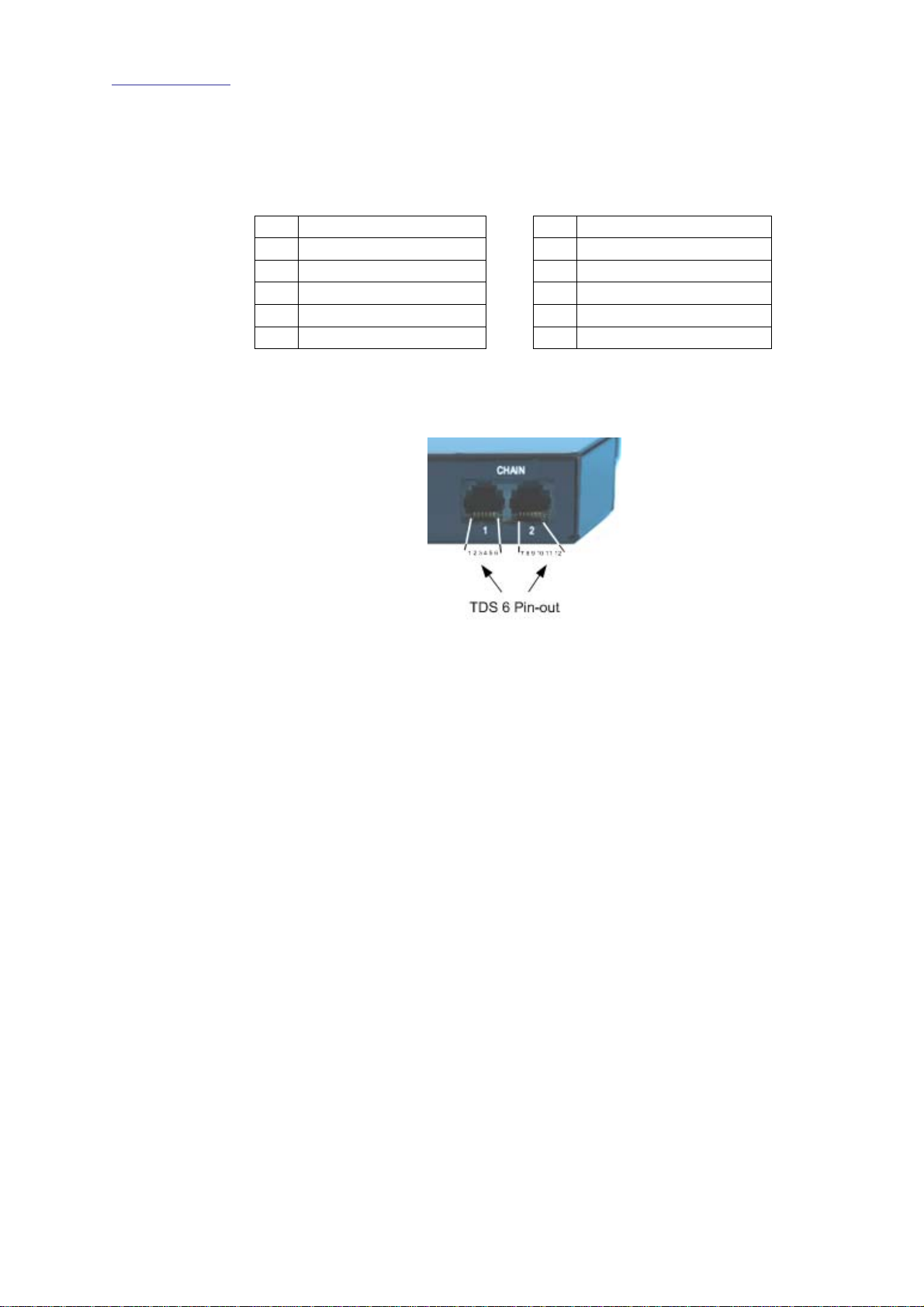
A two-port, six-position, six-contact modular jack on a TDS-6 facilitates
chaining of additional TDS-6 units.
1: GND
2: PPS In +
3: SERIAL In +
4: SERIAL In 5: PPS In 6: 12V DC Power in
7: GND
8: PPS Out +
9: SERIAL Out +
10: SERIAL Out 11: PPS Out 12: 12V DC Power out
Figure 5-4 shows the TDS-6 module chain connector pin-out
configuration.
Figure 5-4. TDS-6 Module Chain Connector Pin-out Configuration.
Copyright© All rights reserved
19
Version 2. 22 September 2005.
 Loading...