

Page 1

DAG 9.2X2 Card User Guide
EDM01-36
Page 2

EDM01-36v10 DAG_9.2X2_Card_User_Guide
Protection Against Harmful Interference
When present on equipment this document pertains
to, the statement "This device complies with part 15
of the FCC rules" specifies the equipment has been
tested and found to comply with the limits for a Class
A digital device, pursuant to Part 15 of the Federal
Communications Commission [FCC] Rules.
These limits are designed to provide reasonable
protection against harmful interference when the
equipment is operated in a commercial environment.
This equipment generates, uses, and can radiate
radio frequency energy and, if not installed and used
in accordance with the instruction document, may
cause harmful interference to radio communications.
Operation of this equipment in a residential area is
likely to cause harmful interference in which case the
user will be required to correct the interference at
their own expense.
Extra Components and Materials
The product that this manual pertains to may include
extra components and materials that are not essential
to its basic operation, but are necessary to ensure
compliance to the product standards required by the
United States Federal Communications Commission,
and the European EMC Directive. Modification or
removal of these components and/or materials, is
liable to cause non compliance to these standards,
and in doing so invalidate the user’s right to operate
this equipment in a Class A industrial environment.
Disclaimer
Website
http://www.endace.com
Copyright 2010 - 2012 Endace Technology Ltd. All Rights reserved.
No part of this publication may be reproduced, stored
in a retrieval system, or transmitted, in any form or
by any means electronic, mechanical, photocopying,
recording, or otherwise, without the prior written
permission of Endace Technology Limited.
Endace, the Endace logos, and DAG, are trademarks
or registered trademarks in New Zealand, or other
countries, of Endace Technology Limited. All other
product or service names are the property of their
respective owners. Product and company names used
are for identification purposes only and such use does
not imply any agreement between Endace and any
named company, or any sponsorship or endorsement
by any named company.
Use of the Endace products described in this
document is subject to the Endace Terms of Trade
and the Endace End User License Agreement (EULA).
Whilst every effort has been made to ensure
accuracy, neither Endace Technology Limited nor any
employee of the company, shall be liable on any
ground whatsoever to any party in respect of
decisions or actions they may make as a result of
using this information.
Endace Technology Limited has taken great effort to
verify the accuracy of this document, but nothing
herein should be construed as a warranty and Endace
shall not be liable for technical or editorial errors or
omissions contained herein.
In accordance with the Endace Technology Limited
policy of continuing development, the information
contained herein is subject to change without notice.
©2010 - 2012 Endace Technology Ltd. Confidential - Version 10 - May 2012
Page 3

EDM01-36v10 DAG_9.2X2_Card_User_Guide
Contents
Introduction 1
The Purpose of this User Guide ................................................................................................................ 1
Overview ................................................................................................................................................ 2
Card features .......................................................................................................................................... 2
System requirements............................................................................................................................... 3
General ............................................................................................................................................... 3
Operating system ................................................................................................................................. 3
Warning - thermal trip ............................................................................................................................. 3
Card description ...................................................................................................................................... 4
DO NOT REMOVE THE BATTERY ........................................................................................................... 4
Card architecture .................................................................................................................................... 5
Line types ............................................................................................................................................... 5
Supported Line Types ........................................................................................................................... 5
Extended functions .................................................................................................................................. 6
Enhanced Packet Processing v2 ............................................................................................................. 6
Inline forwarding .................................................................................................................................. 7
Timed Release TERF (TR-TERF) ............................................................................................................ 7
Triggered Timed Release TERF (TR-TERF) ............................................................................................. 7
Installation 9
DAG software package ............................................................................................................................ 9
PCIe Gen 2.0 Slot .................................................................................................................................... 9
Inserting the DAG card .......................................................................................................................... 10
Ports and Status LEDs ........................................................................................................................... 11
Boot jumper settings ............................................................................................................................. 11
Boot LEDs ............................................................................................................................................. 12
Pluggable optical transceivers ................................................................................................................ 13
Overview ........................................................................................................................................... 13
Optical modules ................................................................................................................................. 13
Power input ....................................................................................................................................... 14
Splitter losses ..................................................................................................................................... 14
Pluggable copper transceivers ................................................................................................................ 14
Configuring the DAG card 15
Introduction .......................................................................................................................................... 15
Firmware images ................................................................................................................................ 15
Resetting DAG card to Operational Settings ......................................................................................... 15
Differences between Windows and Linux installs .................................................................................. 16
Accessing DAG tools in Windows ......................................................................................................... 16
Before configuring the DAG card ......................................................................................................... 17
daginf ................................................................................................................................................ 18
dagdetect .......................................................................................................................................... 18
Setting up the FPGA .............................................................................................................................. 19
Selecting the firmware image to load at power up ................................................................................ 20
Loading new firmware images onto a DAG Card ................................................................................... 20
Programming the FPGA ...................................................................................................................... 20
dagrom .............................................................................................................................................. 21
Preparing the DAG card for use .............................................................................................................. 22
DAG card Configuration and Status ........................................................................................................ 23
Display Current Configuration ............................................................................................................. 23
dagconfig tokens explained ................................................................................................................. 25
dagconfig options ............................................................................................................................... 33
Viewing the DAG card status .................................................................................................................. 34
Interface Status ................................................................................................................................. 34
Universal counters .............................................................................................................................. 35
©2010 - 2012 Endace Technology Ltd. Confidential - Version 10 - May 2012 i
Page 4

EDM01-36v10 DAG_9.2X2_Card_User_Guide
Using your DAG card 37
Introduction .......................................................................................................................................... 37
Basic data capture ................................................................................................................................. 37
Starting a capture session ................................................................................................................... 37
dagsnap ............................................................................................................................................. 38
Capturing data at high speed ............................................................................................................... 39
Viewing captured data ........................................................................................................................... 40
dagbits ............................................................................................................................................... 40
dagbits tests ....................................................................................................................................... 42
Converting captured data ....................................................................................................................... 43
dagconvert ......................................................................................................................................... 43
Using third party applications ................................................................................................................. 47
Transmitting captured data .................................................................................................................... 47
Configuration ...................................................................................................................................... 47
Explicit packet transmission ................................................................................................................. 47
Trace files .......................................................................................................................................... 48
TR TERF ............................................................................................................................................. 48
Synchronizing clock time 51
Overview ............................................................................................................................................... 51
DUCK configuration ................................................................................................................................ 51
Common synchronization ....................................................................................................................... 51
IRIG-B ................................................................................................................................................ 51
Network Time Protocol ........................................................................................................................... 52
Timestamps ........................................................................................................................................... 53
Example ............................................................................................................................................. 53
Readable DUCK ..................................................................................................................................... 54
Reading the current DAG time ............................................................................................................. 54
Performance ....................................................................................................................................... 54
Dagclock ............................................................................................................................................... 55
Card with timing reference ..................................................................................................................... 59
Overview ............................................................................................................................................ 59
Pulse signal from external source ......................................................................................................... 59
Testing the signal ............................................................................................................................... 59
Single card no reference......................................................................................................................... 60
Two cards no reference .......................................................................................................................... 61
Overview ............................................................................................................................................ 61
Synchronizing with each other ............................................................................................................. 61
Synchronizing with host ....................................................................................................................... 61
Connector ............................................................................................................................................. 62
Overview ............................................................................................................................................ 62
Pin assignments .................................................................................................................................. 62
Data formats 65
Overview ............................................................................................................................................... 65
Generic ERF header ............................................................................................................................... 66
ERF 2. TYPE_ETH .................................................................................................................................. 68
Extension Headers (EH) ......................................................................................................................... 69
Introduction........................................................................................................................................ 69
Guidance for stream buffer sizing 71
Selecting stream buffer size .................................................................................................................... 71
Burst duration ..................................................................................................................................... 71
Latency .............................................................................................................................................. 72
Multiple streams .................................................................................................................................... 72
Calculating the stream buffer size ........................................................................................................... 72
Example 1 .......................................................................................................................................... 73
ii ©2010 - 2012 Endace Technology Ltd. Confidential - Version 10 - May 2012
Page 5

EDM01-36v10 DAG_9.2X2_Card_User_Guide
Support 75
Requesting assistance ........................................................................................................................... 76
Support script .................................................................................................................................... 76
Required Information ......................................................................................................................... 76
Severity Levels Described ................................................................................................................... 77
Support request form ......................................................................................................................... 77
Contact details ................................................................................................................................... 77
Version History 79
©2010 - 2012 Endace Technology Ltd. Confidential - Version 10 - May 2012 iii
Page 6

Page 7

EDM01-36v10 DAG_9.2X2_Card_User_Guide - Introduction
Introduction
The Purpose of this User Guide
The purpose of this user guide is to provide you with an understanding of the Endace DAG 9.2X2 card
architecture, functionality and to guide you through the following:
• Installing the card software.
• Installing the firmware.
• Installing the physical card.
• Configuring the card for your specific network requirements.
• Running a data capture session.
• Synchronizing clock time.
• Data formats.
You can also find additional information relating to functions and features of the DAG 9.2X2 card in the
following documents which are available from the Support section of the Endace website at
http://www.endace.com:
•
EDM04-01 DAG Software Installation Guide
EDM04-03 dagflood User Manual
•
EDM04-04 dagfwddemo User Guide
•
EDM04-06 Daggen User Guide
•
EDM04-19 DAG Programming Guide
•
EDM04-21 Libpcap and Third party applications
•
EDM04-25 Counters and Statistics API
•
EDM04-30 dagfilter-loader Software Guide
•
EDM04-31 Enhanced Packet Processing v2
•
EDM04-32 dagmem Software Guide
•
EDM04-33 dag_irigb Software Guide
•
EDM04-34 Configuration & Status API Overview
•
EDM04-37 Windows DAG Software Installation Guide
•
EDM05-01 Time Distribution Server User Guide
•
EDM05-02 TDS 24 Installation Guide
•
EDM11-01 ERF Types
•
PN01-13 DAG Card Quick Start Guide
•
This user guide and the following installation guides are also available in PDF format on the installation
CD shipped with your DAG 9.2X2 card.
•
EDM04-01 DAG Software Installation Guide
EDM04-37 Windows DAG Software Installation Guide
•
©2010 - 2012 Endace Technology Ltd. Confidential - Version 10 - May 2012 1
Page 8

EDM01-36v10 DAG_9.2X2_Card_User_Guide - Introduction
Note:
Overview
The Endace DAG 9.2X2 is a two port, PCIe Gen 2.0 card designed for capture and transmission of
network traffic.
It transfers data at the full speed of the network into the memory of the host computer, with zero packet
loss in even worst-case conditions. Unlike a NIC (Network Interface Card), it actively manages the
movement of network data into memory while consuming a minimal amount of the host computer's
resources. The full attention of the CPU remains focused on the analysis of incoming data without a
constant stream of interruptions as new packets arrive from the network. For a busy network link, this
feature has a turbo-charging effect similar to that of adding a second CPU to the system.
The Endace DAG 9.2X2 is designed for use with optical interfaces. The DAG 9.2X2 provides full line rate
capture of 1 Gigabits per second and 10 Gigabits per second Ethernet per port.
Card features
The following features are available on this DAG card.
Different firmware images may be required. Not all features are available on each firmware image. For
further information on which feature is available in what firmware image, see Firmware images (page
15).
• 100% capture into host memory at full line rate for IP packets from 48 to 9600 bytes.
• 1GE, 10GE LAN and 10GE WAN.
• Timed Release TERF (TR-TERF) & Triggered Timed Release TERF (TR-TERF).
• Enhanced Packet Processing v2 with 32 Stream buffers.
• IRIG-B (Inter Range Instrumentation Group mod B) decoding.
• Conditioned clock with PPS input and local synchronization capability.
• Two SFP+ ports for 1, 10 Gigabit Ethernet.
• PCIe Gen 2.0 bus, 8 lanes.
2 ©2010 - 2012 Endace Technology Ltd. Confidential - Version 10 - May 2012
Page 9

EDM01-36v10 DAG_9.2X2_Card_User_Guide - Introduction
System requirements
General
The minimum system requirements for the DAG 9.2X2 card are:
• A computer, with at least a Intel Xeon or AMD Opteron 1.8GHz or faster and a minimum of 1GB
RAM.
• At least one free PCIe Gen 2.0 slot supporting 8-lane operation.
• Ensure good airflow across the DAG 9.2X2 card heatsink, at least 200 meters per minute (656 linear
feet per minute). Also see Warning - Thermal trip (page 3
• Software distribution requires 60MB free space.
• For details of the supported operating systems, refer either of the following documents.
•
EDM04-01 DAG Software Installation Guide
•
EDM04-37 Windows DAG Software Installation Guide
• The current Release Notes, available on the Endace Documentation and Software CD or the
Endace support website at https://support.endace.com/.
.
Operating system
This document assumes you are installing the DAG 9.2X2 card in a computer which already has an
operating system installed.
).
.
For any queries regarding operating systems, contact Endace Customer Support: [email protected].
Other operating systems
For advice on using an operating system that is substantially different from any of those specified above,
please contact Endace Customer Support at [email protected].
Warning - thermal trip
In order to prevent damage to the DAG 9.2X2 card, the DAG 9.2X2 card has an emergency thermal
response function (thermal trip). Should the internal temperature of the DAG 9.2X2 card exceed 85 ºC
(185 ºF) or fall below 0 ºC (32 ºF), the FPGA will be unloaded, causing the power utilization of the DAG
card to drop. This action may cause the host system to crash and the system requires a power cycle to
recover.
To display the internal temperature of the DAG card, use the dagconfig -m command, see dagconfig
(page 33).
©2010 - 2012 Endace Technology Ltd. Confidential - Version 10 - May 2012 3
Page 10
EDM01-36v10 DAG_9.2X2_Card_User_Guide - Introduction
Note:
Note:
Caution:
Risk of explosion if the battery is replaced by an incorrect type.
Dispose of used batteries carefully.
Card description
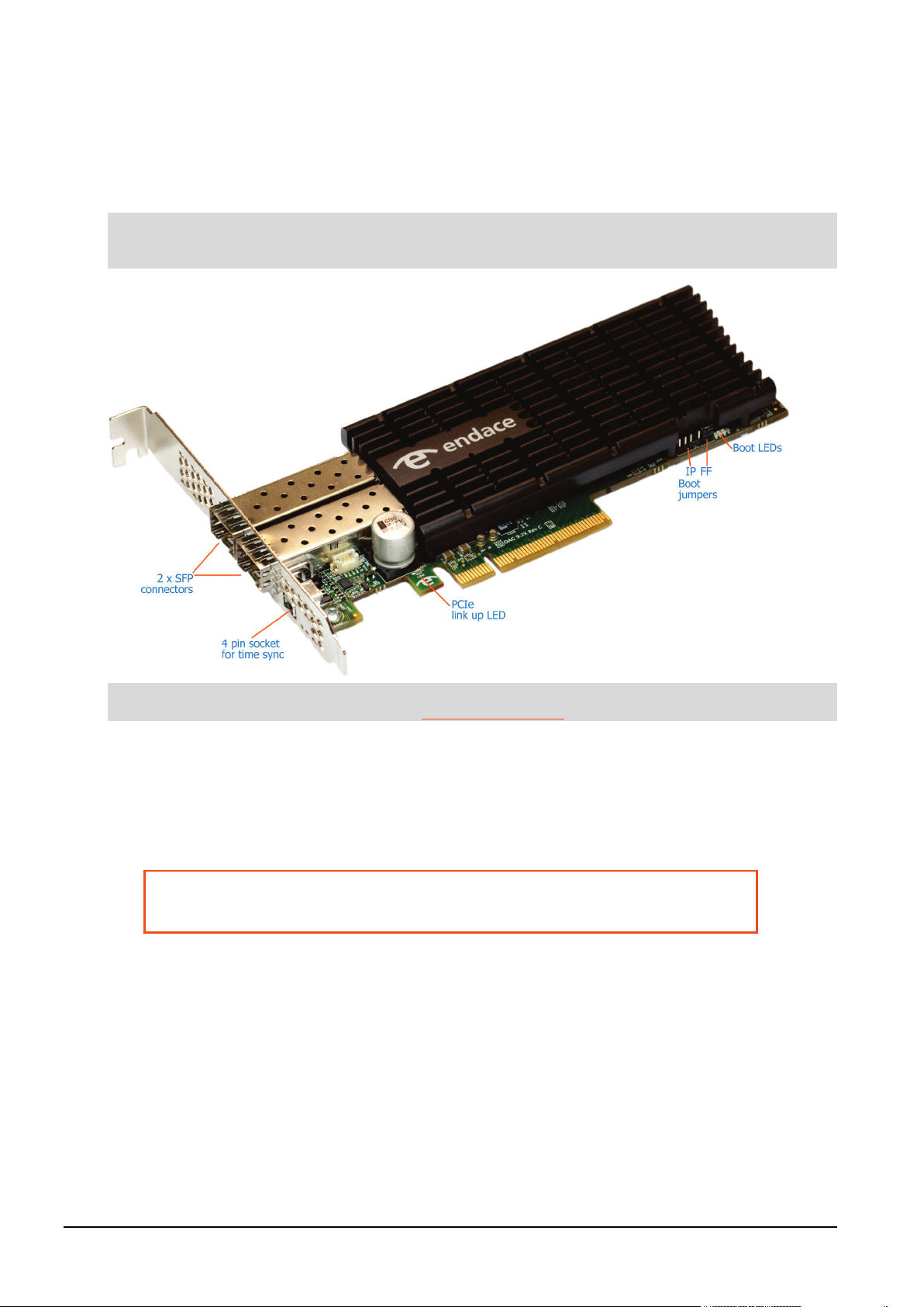
The DAG 9.2X2 has two optical 10 Gigabit Small Form Factor Pluggable (SFP+) interfaces. The two
transceivers can be operated simultaneously allowing a single card to monitor one or both directions of a
full-duplex link. SFP+ transceivers are also backwards compatible with standard SFP interfaces in 1GE
mode.
Performance will be reduced if the DAG 9.2X2 card is inserted in a PCIe Gen 1.0 slot, or if the 8 lane bus
has less than 8 lanes connected. Please check the host computer motherboard specifications.
For further information on Boot jumpers, see Boot jumper settings (page 11).
DO NOT REMOVE THE BATTERY
Removing the battery from a DAG card voids the DAG card warranty.
If battery is removed then the DAG card must be returned to Endace for servicing.
The battery in this product is expected to last a minimum of 10 years.
4 ©2010 - 2012 Endace Technology Ltd. Confidential - Version 10 - May 2012
Page 11
EDM01-36v10 DAG_9.2X2_Card_User_Guide - Introduction
Note:
Note:
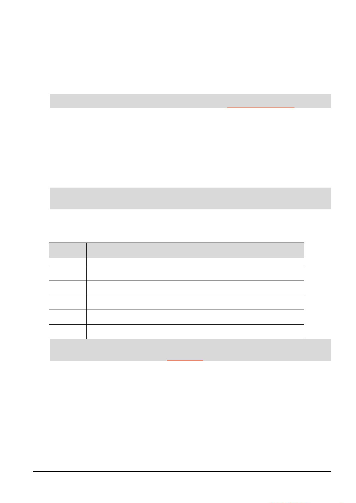
1000Base-T
1000Mbps over four pairs of balanced Cat5 or Cat6 copper cable.
1000Base-SX
1000Mbps over single mode or multi mode fiber optic cable with short wavelength laser
1000Base-LX
1000Mbps over single mode or multi mode fiber optic cable with long wavelength laser
10GBase-SR
10 Gigabit per second over Ethernet multi mode fiber optic cable with short wavelength
10GBase-LR
10 Gigabit per second over Ethernet single mode fiber optic cable with long wavelength
10GBase-ER
10 Gigabit per second over Ethernet single mode fiber optic cable with extended
Note:
Card architecture
Serial optical data received by the SFP+ optical interfaces flows in to the Field Programmable Gate Array
(FPGA).
The FPGA contains the packet processor and the DAG Universal Clock Kit (DUCK) timestamp engine. The
DUCK provides high resolution per-packet timestamps which can be accurately synchronized to an
external Pulse Per Second (PPS) source.
For further information on the DUCK and time synchronization see Synchronizing Clock Time (page 51).
Line types
It is important that you understand the physical characteristics of the network to which you want to
connect. If your configuration settings do not match your network, the DAG 9.2X2 card will not function
as expected.
There are various Ethernet line speeds and corresponding protocols which are identified using the IEEE
naming convention. Each line speed has a set of requirements associated with it relating to the type of
cable, maximum allowable distance, etc.
If you are unsure about which of the following options listed to apply to your network, contact your
Network Administrator for further information.
Supported Line Types
The line types supported by the DAG 9.2X2 card are described below.
Type Description
driver (850nm).
driver (1310nm).
laser driver (850nm).
laser driver (1310nm).
wavelength laser driver (1550nm).
For more detailed information regarding Ethernet line types and speeds, please refer to IEEE Standard
802.3AE available from the IEEE website at www.ieee.org.
©2010 - 2012 Endace Technology Ltd. Confidential - Version 10 - May 2012 5
Page 12

EDM01-36v10 DAG_9.2X2_Card_User_Guide - Introduction
Extended functions
Enhanced Packet Processing v2
With the Enhanced Packet Processing v2 capability the following types of enhanced capabilities can be
achieved:
1. Filtering: Filtering compares the fields in the packet's protocol headers to a list of user defined filter
rules. As a result, the packets matching the filter are tagged with a user defined color value. This
color value is subsequently used to steer the packet to specific stream buffer(s) or to drop the
packet.
2. Hash Load Balancing (HLB): The HLB module takes the packets and applies one of a number of
user selectable load balancing algorithms. This results in each packet being tagged with a bin
number. The bin number is used to help determine the stream the packets are sent to. The user can
choose the number of bins used in the packet tagging.
HLB is typically used to optimize the parallel processing done by multi-core servers, since each core
will only see a subset of the full traffic load. The user normally wants to distribute traffic equally (or
roughly equally) across the stream buffers while preserving "flow coherence", meaning, all packets
associated with a single TCP/IP session must always go to the same stream buffer. Hashing is the
tool used to classify the flow coherent streams and mathematically assign a "bin number" to each
packet. Bin numbers are then associated with specific stream buffers to achieve the desired load
balancing. The hashing algorithms are "flow coherent" so all packets that are a part of a particular
session will be tagged with the same bin number.
3. Steering: This is where the results of the previous steps are used to determine which stream the
packet should be steered to. Optionally, the interface / port number the packet originated from can
also be used in the steering process. The rules that determine how the packet steering is
accomplished are defined by the user. This gives a large amount of flexibility in the packet steering
process. The user can choose to use some, all or none of the color, HLB bin value and interface /
port numbers in the steering process.
4. Duplication: One of the unique benefits of the Steering feature is the ability to steer the same
packet to multiple streams. Packet duplication can simplify software architectures where different
applications need to process the same packet. For example, all traffic can be sent to stream buffer 0
for use by a capture to disk application, while only a subset of traffic is sent to stream buffer 2 for
handling by a traffic analysis application. For this document, packet duplication is defined as writing
a single packet into more than one stream buffer. It does not mean writing the packet twice into the
same stream buffer.
For further details refer to the following documents:
•
EDM04-30 dagfilter-loader Software Guide
EDM04-31 Enhanced Packet Processing v2
•
EDM04-35 dagcat-setup Software Guide v2
•
6 ©2010 - 2012 Endace Technology Ltd. Confidential - Version 10 - May 2012
Page 13

EDM01-36v10 DAG_9.2X2_Card_User_Guide - Introduction
Inline forwarding
The DAG 9.2X2 card supports inline forwarding which enables the card to receive and transmit packets
directly from a single memory buffer. This allows you to forward packets from the DAG card receive
interface(s) to the DAG cards transmit interface(s) without the requirement to copy them. Using inline
forwarding you can receive, inspect, filter and forward packets between ports.
dagfwddemo which is a tool supplied with your DAG card demonstrates how you can apply a user-defined
Packet Filter (BPF) to the traffic forwarded by the DAG card. Packets which match the filter are
forwarded, while packets that do not match are dropped.
For more detailed information on inline forwarding and using dagfwddemo please refer to the
dagfwddemo User Guide
available from the support section of the Endace website at
EDM04-04
http://www.endace.com.
Timed Release TERF (TR-TERF)
The Timed Release TERF (TR-TERF) module is an option that enables you to retransmit an ERF packet
trace while reproducing the time intervals of the packets within that stream. It is able to transmit on all
channels.
TR-TERF has two modes of operation.
• No Delay Mode.
• Relative Timed Release Mode.
Triggered Timed Release TERF (TR-TERF)
The Triggered Timed Release TERF (TR-TERF) module extends the functionality of TR-TERF by setting an
absolute time at which to start the transmission is to start. This enables synchronization of multiple
replay sessions across multiple DAG cards and even systems, provided that the DAG card clocks are
synchronized.
©2010 - 2012 Endace Technology Ltd. Confidential - Version 10 - May 2012 7
Page 14

Page 15

EDM01-36v10 DAG_9.2X2_Card_User_Guide - Installation
Caution:
The DAG 9.2X2 card software must be installed before the card itself is
physically installed into the computer.
Installation
DAG software package
The latest DAG Software package must be installed before you install the DAG 9.2X2 card itself. For
details on installing the latest DAG Software package, refer to the following:
•
EDM04-01 DAG Software Installation Guide
EDM04-37 Windows DAG Software Installation Guide
•
PCIe Gen 2.0 Slot
The DAG 9.2X2 card operates on an 8 lane PCIe Gen 2.0 bus and can be installed in any free 8 lane PCIe
Gen 2.0 slot.
The PCIe Gen 2.0 bus architecture allows multiple DAG cards to be installed without affecting the
bandwidth used by each DAG 9.2X2 card.
©2010 - 2012 Endace Technology Ltd. Confidential - Version 10 - May 2012 9
Page 16
EDM01-36v10 DAG_9.2X2_Card_User_Guide - Installation
Warnings:
Electro-Static Discharge (ESD): It is very important to protect both the
computer and the DAG 9.2X2 card from damage by ESD. Failure to do so
could cause damage to components and subsequently cause the card to
partially or completely fail.
DO NOT hold the DAG 9.2X2 card by the battery cage. The battery cage can
be easily damaged and can cause your DAG 9.2X2 to need reprogramming.
DO NOT REMOVE THE BATTERY (page 4).
Caution:
Ensure good airflow across the DAG 9.2X2 card heatsink, at least 200
meters per minute (656 linear feet per minute).
Inserting the DAG card
1. Turn power to the computer OFF.
2. Remove the PCIe Gen 2.0 bus slot screw and cover.
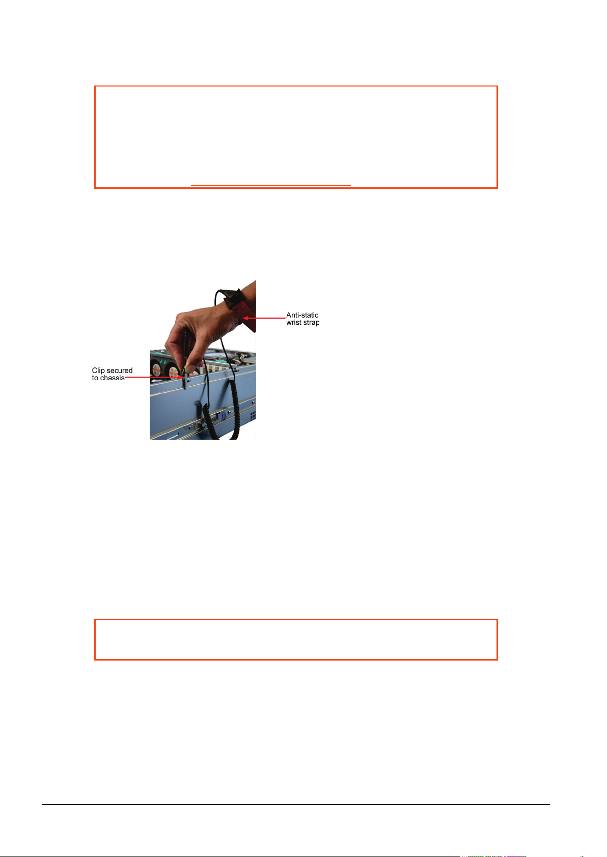
3. Using an approved ESD protection device attach the end with the strap to your wrist and pull or clip
firmly so there is firm contact with your wrist.
4. Securely attach the clip on the other end of the strap to a solid metal area on the computer chassis
as shown below.
5. Hold the DAG 9.2X2 card with one hand on the front bracket and two or three fingers on the card
edge. This ensures damage does not occur to the card or its components.
6. Insert the DAG 9.2X2 card into PCIe Gen 2.0 bus slot ensuring it is firmly seated.
7. If this DAG card requires an external power supply, complete the following steps:
a. Connect the supplied (or equivalent) power cable to the external power connector on the DAG
card.
b. Connect the cable to the appropriate power connector on your server's power supply unit.
8. Check the free end of the card fits securely into the card-end bracket that supports the weight of the
card.
9. Secure the card with the bus slot cover screw.
10. Turn power to the computer ON.
11. Ensure the blue (FPGA successfully programmed) LED on the DAG card illuminates.
10 ©2010 - 2012 Endace Technology Ltd. Confidential - Version 10 - May 2012
Page 17
EDM01-36v10 DAG_9.2X2_Card_User_Guide - Installation
Warning:
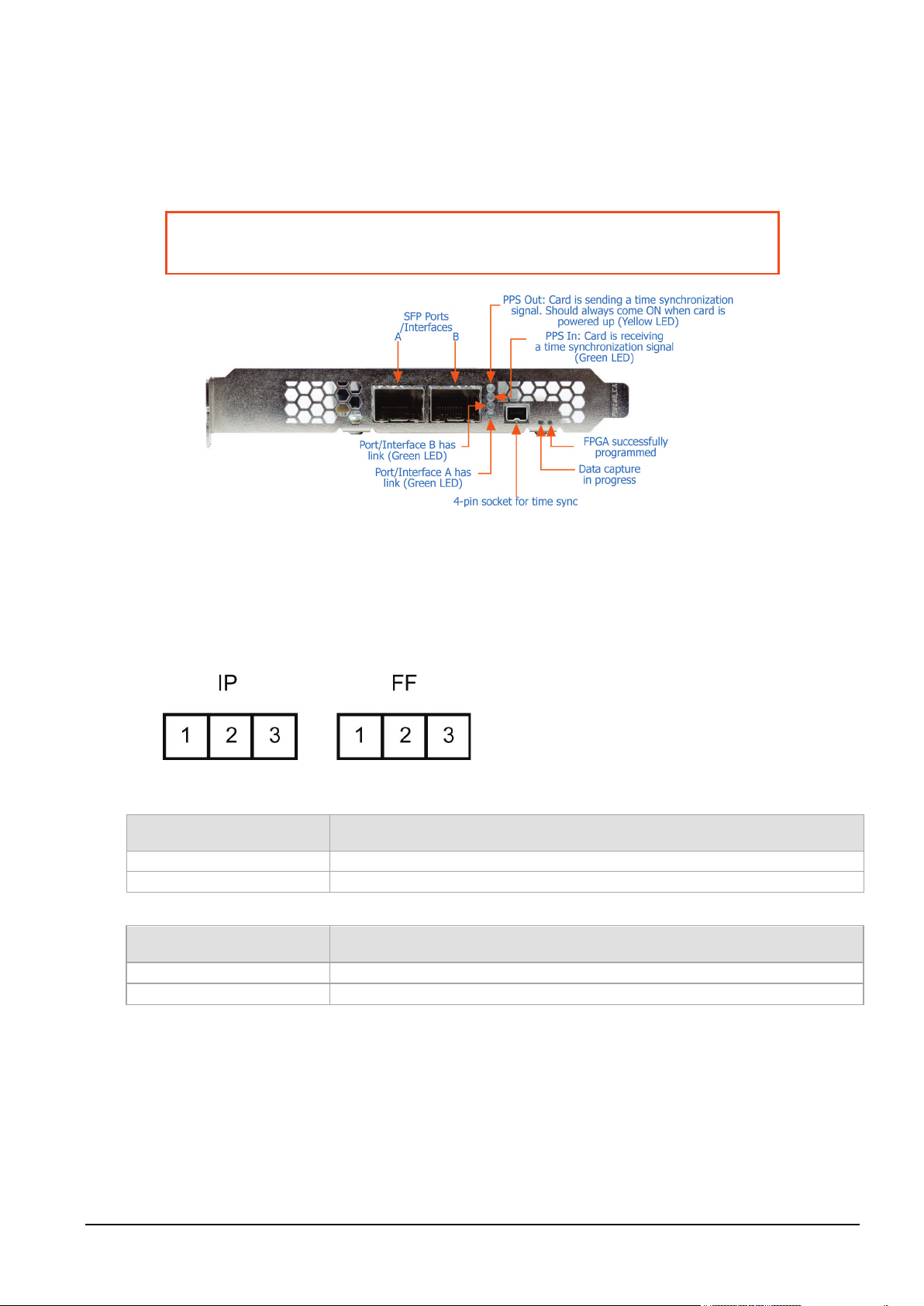
Connect only a PPS input to the 4 pin time synchronization socket.
Connecting anything else to this socket may damage the DAG card.
IP Jumper settings
1 & 2
Used in development. Do not use.
2 & 3 or jumper not fitted
Normal operation of the DAG card.
FF jumper settings
1 & 2
Loads the factory image into the FPGA at power on.
2 & 3 (or jumper not fitted)
Loads the user defined image into the FPGA at power on.
Ports and Status LEDs
The DAG 9.2X2 card has two industry standard port connectors for network connections.
In addition there is a 4-pin socket located beside the port connectors for connection to an external time
synchronization source.
Boot jumper settings
The DAG 9.2X2 has two sets of jumpers mounted on the DAG card which control the card's boot
behavior:
• IP (Inhibit Program)
• FF (Force Factory)
Jumper set between Definition
Jumper set between Definition
©2010 - 2012 Endace Technology Ltd. Confidential - Version 10 - May 2012 11
Page 18
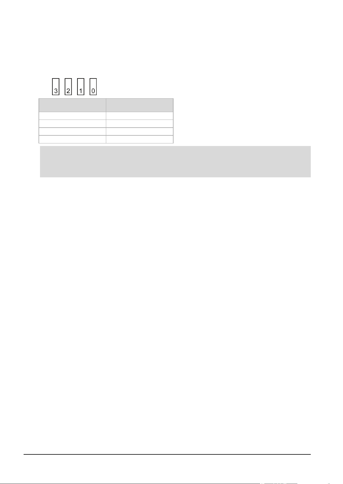
EDM01-36v10 DAG_9.2X2_Card_User_Guide - Installation
3
Green
2
Green
1
Green
0
Red
Notes:
Boot LEDs
The following tables describe the Boot LED configurations of the DAG 9.2X2. The Boot LED's are to the
right of the Boot Jumpers.
Boot LED numbering:
LED Color
•
If the blue 'FPGA programmed' LED (on the front of the DAG card) is off or flashing - contact Endace
Support.
•
If the red Boot LED is flashing, contact Endace Support.
12 ©2010 - 2012 Endace Technology Ltd. Confidential - Version 10 - May 2012
Page 19
EDM01-36v10 DAG_9.2X2_Card_User_Guide - Installation
Caution:
To prevent damage to the DAG card, ensure you select the correct
transceiver type for the optical parameters of the network to which you
want to connect.
Note:
TXR-1000SX
1000BASE-SX
770
860
-20 0 830
860
-9
-3.5
TXR-1000LX
1000BASE-LX
1270
1600
-22 0 1270
1360
-9.5
-3
TXR-10G 850 MM
10GBASE-SR
840
860
-11.1
0.5
840
860
-5
-1
TXR-10G 1310
10GBASE-LR/LW
1260
1600
-12.6
1260
1355
-5.2
0.5
TXR-1G/10G 850
1G/10G BASE-SR
840
860
-17
0.5
840
860
-9.5
-1
TXR-1G/10G
1G/10G BASE-LR
1260
1600
-19 1260
1355
-11
-3
TXR-10G 1550
10GBASE-ER
1260
1600
-15.8
-1
1530
1565
-4.7
4
Pluggable optical transceivers
Overview
The DAG card's SFP+ optical transceivers consist of the following two parts.
• Mechanical chassis attached to the circuit board.
• Transceiver unit which may be inserted into the chassis.
You can connect the transceiver to the network via LC-style optical connectors. For further information on
pluggable optical transceivers please refer to the Endace website at http://www.endace.com.
Optical modules
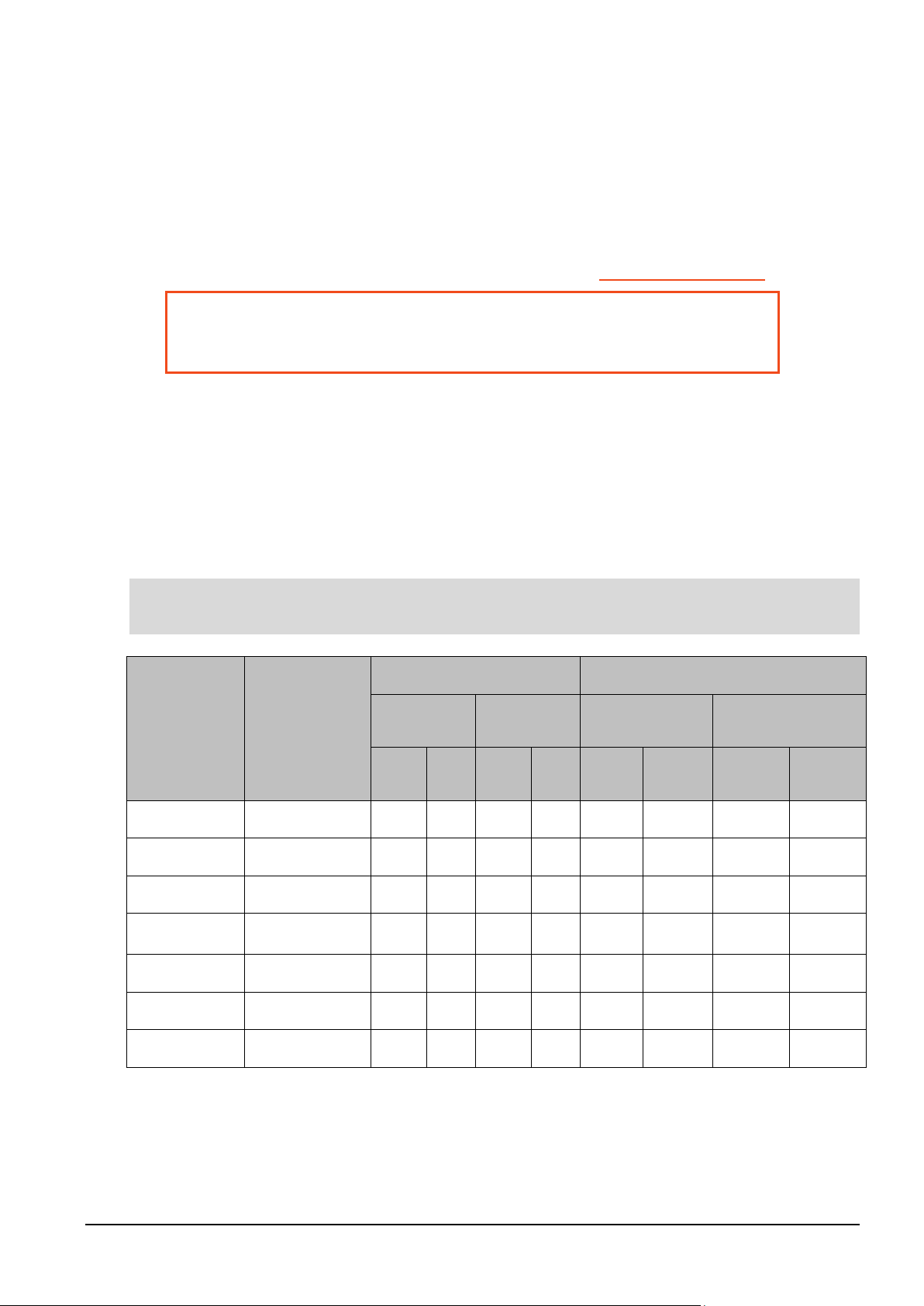
The optical power range depends on the particular SFP+ module that is fitted to the DAG card. Optics
modules are supplied in either Single or Multi mode. See the following table for details.
Optical power is measured in dBm, decibels relative to 1 mW where 10 dB is equivalent to a factor of 10
in power. A negative optical power value indicates power that is less than 1 mW. The most sensitive
devices can work at power levels down as low as -30dBm or 1µW.
To confirm card port light levels, use an optical power meter.
Covering the card ports with LC-style plugs when they are not in use is highly recommended, to prevent
dust and mechanical hazards affecting optics.
Receive Characteristics Transmit Characteristics
Product
Number
SFP+
SM SFP+
MM SFP+
Network
Support
Multi mode
Single mode
Multi mode
Single mode
Multi mode
Wavelength
(nm)
Min Max Min Max Min Max Min Max
Sensitivity
dBm (OMA)
Wavelength
(nm)
Tx Power dBm
(OMA)
©2010 - 2012 Endace Technology Ltd. Confidential - Version 10 - May 2012 13
1310 SM SFP+
SM SFP+
Single mode
Single mode
Transmit power and the receive sensitivity is specified as OMA - Optical Modulation Amplitude.
Page 20
EDM01-36v10 DAG_9.2X2_Card_User_Guide - Installation
Note:
Note:
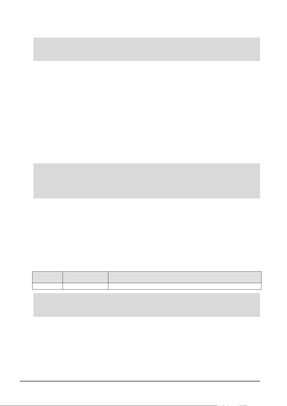
TXR-1000TX
1000 Base-T
less than 1.25 Gbps (RJ-45 IEEE 802.3)
Note:
Power input
The optical power input to the DAG card must be within the receiver’s dynamic range. See the previous
table for details. If it is slightly outside of this range it will cause an increased bit error rate. If it is
significantly outside of this range the system will not be able to lock onto the signal.
When power is above the upper limit the optical receiver saturates and fails to function. When power is
below the lower limit the bit error rate increases until the device is unable to obtain lock and fails. In
extreme cases, excess power can damage the receiver.
When you set up the DAG card you should measure the optical power at the receiver and ensure that it is
within the specified power range. If it is not, adjust the input power as follows:
• Insert an optical attenuator if power is too high, or
• Change the splitter ratio if power is too high or too low.
Splitter losses
Splitters have the insertion losses either marked on their packaging or described in their accompanying
documentation. General guidelines are as follows:
• A 50:50 splitter will have an insertion loss of between 3 dB and 4 dB on each output.
• 90:10 splitter will have losses of about 10 dB in the high loss output, and <2 dB in the low loss
output.
Endace recommends that you do not use a combination of single-mode and multi-mode fibers and optics
modules on the same link, as the quality of the received signal cannot be guaranteed.
If you have no choice but to mix single-mode and multi-mode, please be aware that a single mode input
connected to a multi-mode fiber will have some attenuation but may still be acceptable. However a multimode input connected to a single-mode fiber will likely have large and unpredictable losses.
Pluggable copper transceivers
The DAG card supports industry standard Small Form-factor pluggable (SFP) copper transceivers.
The transceivers consist of two parts:
• Mechanical chassis attached to the circuit board
• Transceiver unit which may be inserted into the chassis
Endace recommends that you use Cat6 copper cable. The DAG card copper module specification is shown
below:
Part Type Data Rate
If a copper transceiver is unplugged and then plugged in again you must run
initialize the transceiver for the link configuration. It also checks the compatibility of all the modules with
the DAG card, and will not power on mismatched modules.
dagconfig default
to
14 ©2010 - 2012 Endace Technology Ltd. Confidential - Version 10 - May 2012
Page 21
EDM01-36v10 DAG_9.2X2_Card_User_Guide - Configuring the DAG card
dag92x2pci-bfs-eth.efb
(dag92x2pci-bfs-eth...)
Note:
Configuring the DAG card
Introduction
Configuring the DAG 9.2X2 card requires the following steps:
• Setting up the FPGA (page 19
).
• Preparing the DAG card for use (page 22).
• Configuring the DAG Card (page 23).
• Viewing the DAG card statistics (page 34).
Once the DAG 9.2X2 is configured, you can begin using it.
See Using your DAG card (page 37
) for details on capturing data.
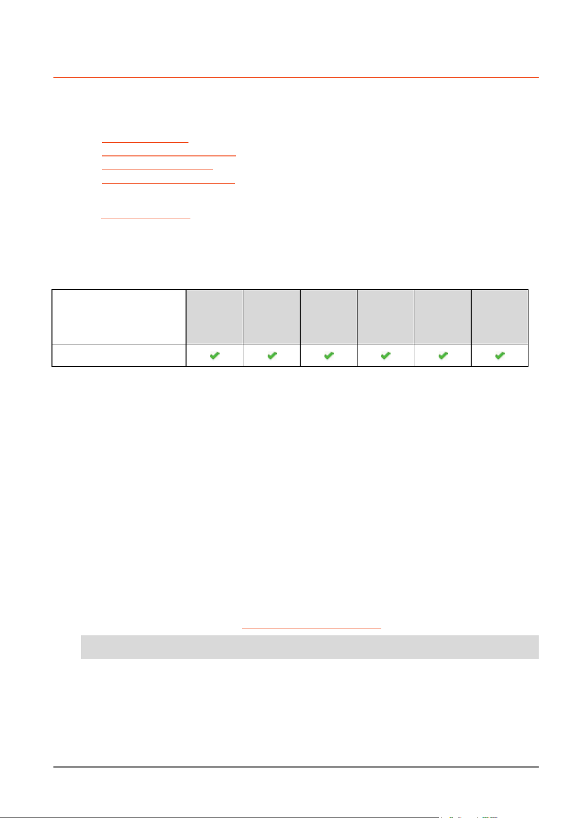
Firmware images
The following lists the features available on each firmware image available on this DAG card.
FPGA image
(Software version string)
1 Gigabit
Ethernet
10 Gigabit
Ethernet
LAN
10 Gigabit
Ethernet
WAN
Enhanced
Packet
Processing
v2
TR-TERF TTR-TERF
The software version strings are displayed in the dagconfig output and when using the dagrom -x
command. They include a version number and creation date.
Resetting DAG card to Operational Settings
To ensure a DAG card has the correct operational settings, the dagconfig -dX default command must
be run after any of the following operations. (Where X is the device number of the DAG card you want to
configure).
• booting the host system,
• installing or updating the DAG drivers,
• disabling and re-enabling the DAG driver,
• programming the DAG card firmware (i.e. dagrom -p), or
• resetting the DAG card (dagreset).
• after inserting a new XFP/SFP/SFP+ transceiver module.
This command resets the specified DAG card to operational settings for the DAG cards default network
mode.
Once this command is run, the DAG card is ready to capture and transmit using the default network
mode settings (i.e. 10 G, Ethernet, SONET etc).
For further details on DAG tools, see Accessing DAG tools in Windows (page 16
).
Depending on your current network's mode, you may need to change the network mode settings.
©2010 - 2012 Endace Technology Ltd. Confidential - Version 10 - May 2012 15
Page 22

EDM01-36v10 DAG_9.2X2_Card_User_Guide - Configuring the DAG card
Note:
•
•
•
•
Notes:
Note:
Differences between Windows and Linux installs
With the following few exceptions, everything about using the DAG software and API in the Linux and
Windows environments are the same:
• The registry editing capabilities of DAG Devices replaces the functionality of Linux’s dagmem and
dagload.
• winpcap replaces libpcap.
• Only DAG tools applicable to the supported DAG cards are available in this release. For a list of
supported tools see the following list.
Not all DAG software releases support MS Windows, refer to the applicable release notes for specific
details.
Supported DAG tools in Windows
The following is a list of the DAG tools supported under the Windows operating system.
dagbits
• dagcat-setup
• dagclock #
• dagconfig
• dagconvert
•
•
# - These DAG tools operate differently from the Unix equivalent.
dagdetect runs automatically each time the WinDAG Command Prompt window opens.
dagdetect
• dagfilter-loader
• dagflood
• daggen
• daginf
dag_irigb
• dagpps
• dagreset
• dagrom
• dagsnap
dagsnapbis
• dagsort
• dsm_loader
Windows only DAG tools
The following DAG tools are available only within the Windows environment:
• DAG Devices - replaces the functionality of dagmem and dagload.
• dagsrat - an information tools that allows the user to view the ACPI Static Resource Affinity Table if it
exists on the system where the tool is run.
• daguninstall - Correctly uninstalls the dag software (forcing it if necessary).
• dagwpcap - Updates WinPcap with DAG enabled components which allow WinPcap to see live traffic
from a DAG card.
For further details refer to
EDM04-37 Windows DAG Software Installation Guide
.
Accessing DAG tools in Windows
Once the DAG software is installed you can start to use the DAG tools via a command prompt.
To access a command prompt in the Windows Server operating system(2003 or 2008), use the WinDAG
Command Prompt tool. This tool opens a command window in the appropriate directory. The window is
configured to display a wider than normal command window with orange text.
WinDAG Command Prompt
The WinDAG Command Prompt tool opens a custom command window which enables you access to the
supported DAG tools. It opens in the directory containing the DAG tools.
When the WinDAG Command Prompt tool opens it:
• provides a wider command window in order to see the DAG tool outputs.
• automatically displays details about the installed DAG cards.
The DAG tools use the Unix style operands, i.e. they use "-" instead of "/".
16 ©2010 - 2012 Endace Technology Ltd. Confidential - Version 10 - May 2012
Page 23

EDM01-36v10 DAG_9.2X2_Card_User_Guide - Configuring the DAG card
Note:
Note:
Before configuring the DAG card
Before configuring the FPGA, ensure the following actions have been completed on each installed DAG
card:
• memory allocated to each DAG card.
• DAG drivers installed for each DAG card.
Before using the DAG card to capture or transmit traffic remember to run
(Where X is the device number of the DAG card you want to configure).
For further details, see Resetting DAG card Operational Settings (page 15).
Linux operating systems
In Linux operating systems, use the following applications:
•
dagmem has been run and memory allocated to each installed DAG card.
dagload has been run so that all DAG drivers have been installed.
•
dagmem
dagmem
For further details, refer to the
01 DAG Software Installation Guide
controls the amount of memory assigned to each DAG card. To change the memory assignments
must be reloaded, which may require a reboot. Refer to
Installing the drivers
section for the required operating system in
EDM04-32 dagmem Software Guide
.
dagconfig -dX default
.
EDM04-
Windows Server operating systems
In Windows Server operating systems, use the DAG Devices tool to allocate memory to each installed
DAG card, and install DAG drivers for each installed DAG card.
For further details, refer to the
Software Installation Guide
Configuring DAG card parameters
.
section in
EDM04-37 Windows DAG
©2010 - 2012 Endace Technology Ltd. Confidential - Version 10 - May 2012 17
Page 24
EDM01-36v10 DAG_9.2X2_Card_User_Guide - Configuring the DAG card
-d,--device <device>
The DAG device to use. Default is d0.
-h,--help
Displays the MAN pages help for this tool.
-v,--verbose
Sets the verbosity level of the displayed information. 0 (basic) to 3 (full).
-V,--version
Display version number of daginf and of the installed DAG software.
id 1
txstreams 1
id 1
Note:
-c,--count
Displays the number of installed DAG cards in the system.
-d,--device
<device>
DAG device to use.
-h,--help, ?,--usage
Displays the help associated with this software.
-i,--ifaces
Displays the number of physical interfaces on the specified DAG card.
-n,--name
Displays the name of a specified DAG card.
-p,--path
Displays the name of a specified DAG card in a form suitable for use as a filesystem path
-v,--verbose
Increase verbosity.
-V,--version
Display version information.
Note:
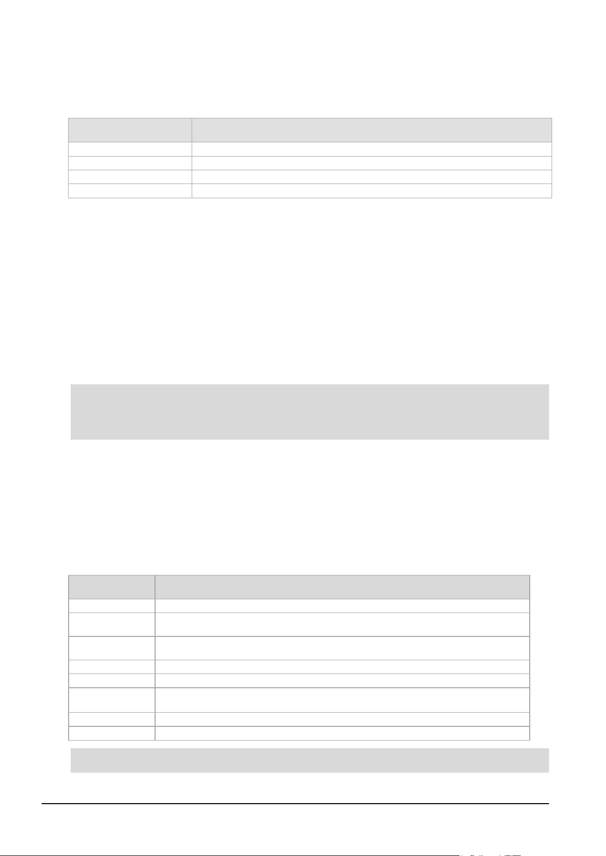
daginf
daginf is the information utility for DAG cards. By default daginf displays summary information about
all DAG cards installed in the system. The available options in
Option Description
The following is an example daginf output for the DAG 9.2X2:
Linux Windows
daginf are as follows:
model DAG 9.2X2
device 0x920e
board rev 2
phy addr 0xbd400000
buf size 33554432 (32MB)
iom size 65536 (64kB)
bus addr 0000:07:00.0
Memory at node 0: 8192 pages (32MB)
copro Built-in
rxstreams 32
model DAG 9.2X2
device 0x920e
board rev 3
bus addr 0x00000005205d9000
buf size 1073741824 (1024MB)
iom size 65536 (64kB)
mem NUMA node 1
copro Built-in
rxstreams 32
txstreams 1
•
Depending on the installed operating system, some options do not display.
•
The "mem NUMA node" will be displayed if the system is able to determine the NUMA node for the
stream buffer.
dagdetect
dagdetect displays the currently installed DAG cards and associated details.
This includes the following details:
• current device number on this system.
• the number of ports on this DAG card.
• the card code specific to this DAG card.
• the DAG card type and specific board revision.
Option Description
(i.e. no whitespace). Implies '--name'.
Dagdetect runs automatically each time the WinDAG Command Prompt window opens.
18 ©2010 - 2012 Endace Technology Ltd. Confidential - Version 10 - May 2012
Page 25

EDM01-36v10 DAG_9.2X2_Card_User_Guide - Configuring the DAG card
Setting up the FPGA
All DAG cards have at least one Field-Programmable Gate Array (FPGA). The FPGA contains the firmware
for the installed DAG card. The firmware defines how the DAG card operates when capturing data and
contains the specific configuration.
For the FPGA on the DAG 9.2X2 there are up to four firmware images stored in ROM:
• The factory image - contains fixed basic functionality for operating the DAG card. It cannot be
overwritten by the user.
• The user images in slots 1 to 3 - User image #1 is programmed at the factory. Other user images
may or may not be pre-programmed. User images can be updated by the user either to update to a
new release, or to load an user image with different functionality than that originally shipped from
the factory.
By default, the DAG 9.2X2 card boots using the user image in slot 1, unless the Force Factory jumper
is fitted. For more details on the Force Factory jumper, see Boot jumper settings (page 11
Booting from the factory image is only required if the DAG card cannot boot from any of the user images
as a result of a ROM programming error.
).
©2010 - 2012 Endace Technology Ltd. Confidential - Version 10 - May 2012 19
Page 26
EDM01-36v10 DAG_9.2X2_Card_User_Guide - Configuring the DAG card
Note:
0
Factory image
1
User image 1
2
User image 2
3
User image 3
Note:
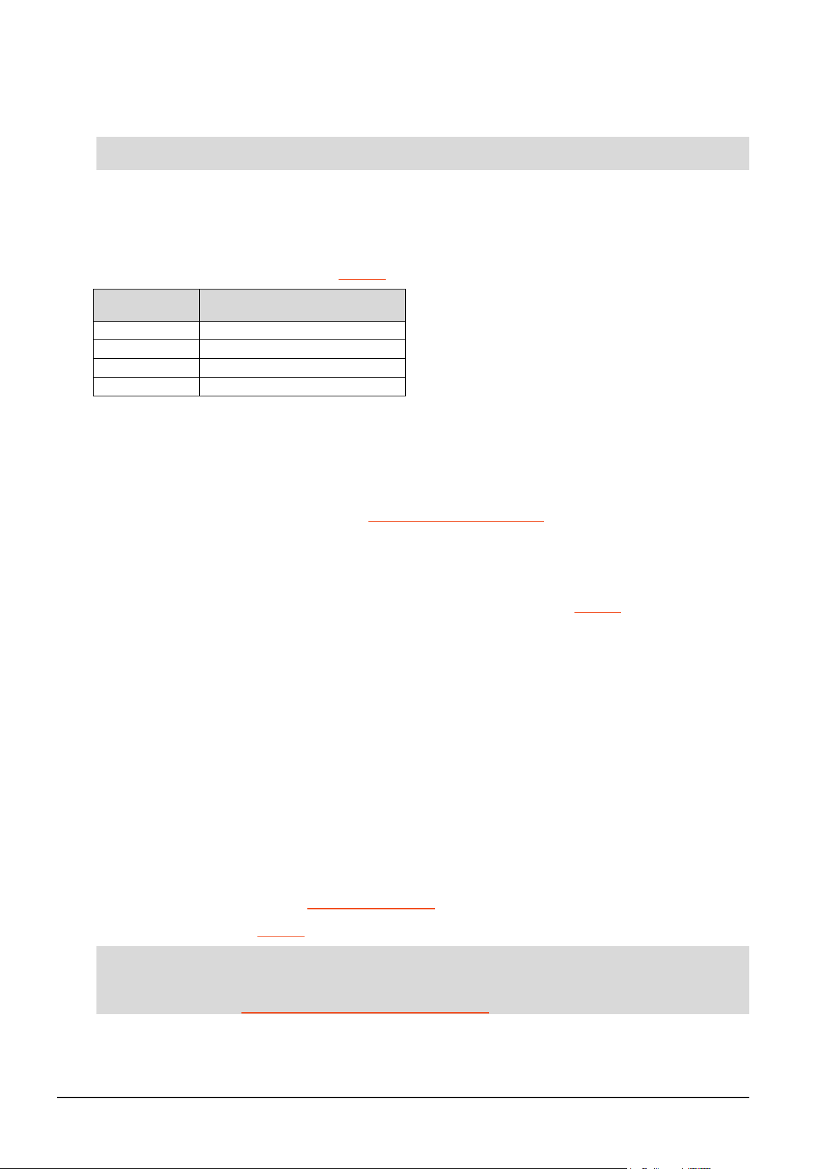
Selecting the firmware image to load at power up
By default, the DAG 9.2X2 card loads user image from slot 1 at power up.
This setting is overridden if the Force Factory jumper is set.
To change the power up user image slot number, use the following command:
dagrom -dX -qY
• Where X is the device number of the DAG card you want to configure.
• Where Y is the number of the new default power up user image.
For details on the dagrom options, see dagrom (page 21
Slot (Y) Image loaded
For example, to set the user image in slot 3 as the power up image, type:
dagrom -d0 -q3
).
Loading new firmware images onto a DAG Card
New DAG card firmware images are released regularly by Endace as part of software releases. They can
be downloaded from the Endace website at https://support.endace.com/.
Endace recommends you use the dagrom -ryv command when loading images from the computer to
the FPGA on the DAG card.
The
-r option invokes a comparison of images on the computer and in the DAG card. Newer versions are
automatically loaded onto the DAG card and programmed into the FPGA: see dagrom (page 21
). This
eliminates unnecessary reprogramming of the FPGA and extends its life.
Programming the FPGA
If required you can program new user images into any of the three user image slots on the FPGA.
For example, for the DAG 9.2X2 card use:
1. Type the following command:
dagrom -dX -rv -y -qY -f dag92x2pci-bfs-eth.efb
• Where X is the device number of the DAG card you want to configure
• Where Y is the user image slot number in which to load the new user image. This image is
marked
The filename of the firmware image may differ from the above depending on the version required.
2. Power cycle the chassis.
On power cycle the user image marked to be loaded becomes active - provided the boot jumpers are
not set to Force Factory (FF), see Boot jumper settings (page 11
to be loaded.
).
For more information see dagrom (page 21).
Before using the DAG card to capture or transmit traffic remember to run
dagconfig -dX default
(Where X is the device number of the DAG card you want to configure).
For further details, see Resetting DAG card Operational Settings (page 15).
20 ©2010 - 2012 Endace Technology Ltd. Confidential - Version 10 - May 2012
Page 27
EDM01-36v10 DAG_9.2X2_Card_User_Guide - Configuring the DAG card
-a,--alternate-half
Use alternate (stable) half. [Default is current half.] Factory / User.
Note:
-A,--entire-rom
Entire ROM. [Default is current half only.]
Note:
-b,--swid-rom-check
Check if there is a SWID on the ROM.
-c,--cpu-region
<region>
Access CPU region: c=copro, b=boot, k=kernel, f=filesystem, a=all.
--continue
Continue on erase error.
-d,--device <device>
DAG device to use.
-e,--erase
Erase ROM. [Default is read.]
-F,--disable-cfi-fast
Disable fast program option for CFI mode. Use only on the advice of Endace.
-f,--file <filename>
File to be read when programming ROM. There are multiple FGPA images per DAG
--force
Force loading firmware. Not recommended unless absolutely necessary - use only
Caution:
-g,--rom-number <rom>
Access specified ROM controller. [Default is 0.]
-h,--help -?,--usage
This page.
-i,--halt-ixp
Halt the embedded IXP Processor (DAG 7.1S only).
-I,--incr
Increment ROM. [Default is read.] Use only on the advice of Endace.
-j,--swid-rom-check-key
<key>
Check the ROM SWID key with the one supplied.
-l,--hold-bus
Hold PBI bus from XScale (DAG 3.7T only).
-m,--swid-key <key>
Hexadecimal key for writing the Software ID (aka SWID).
-n,--fpga-number <FPGA
number>
Specify which FPGA to load the specified image into on next power cycle. Default
-o,--swid-rom-read
Read SWID from ROM.
-p,--program-current
Program current User 1 Xilinx image into FPGA.
Caution:
-q,--image-number
Specify the image number for operations (-w, -r, -y, -e).
Note:
-r,--reprogram
Reprogram ROM (may imply erase and write).
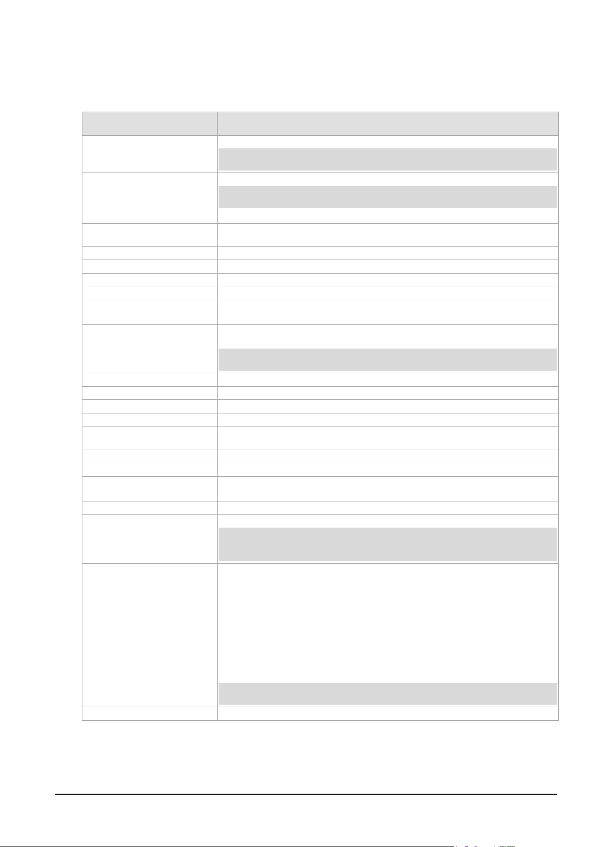
dagrom
dagrom is a software utility to configure the FPGA on Endace DAG cards. The following table lists dagrom
options.
Option Description
Not applicable to DAG 7.4S, 7.5G2/G4, 9.2X2 or 9.2SX2 .
Not applicable to DAG 7.4S, 7.5G2/G4, 9.2X2 or 9.2SX2 .
card, covering the different versions, ERF, BFS, DAM etc.
with extreme caution.
May prevent DAG card operation or even damage the DAG card.
FPGA number is 0.
Do not use with DAG 7.4S, 7.5G2/G4, 9.2X2, 9.2SX2 DAG 9.2X2, 9.2SX2, see -q
below.
<image number>
• 0.factory image
• 1. user image 1,
• 2. user image 2
• 3. user image 3
When used with the -r or -w options, -q changes into which slot the image is
loaded.
When used without the -r or -w options, -q does not change the image itself,
rather it sets the "boot next" flag.
Use with DAG 7.4S, 7.5G2/G4, 9.2X2, 9.2SX2 only.
©2010 - 2012 Endace Technology Ltd. Confidential - Version 10 - May 2012 21
Page 28
EDM01-36v10 DAG_9.2X2_Card_User_Guide - Configuring the DAG card
--reset-method
Specify the method to reprogram the card.
Caution:
-s,--swid-rom-write
<swid>
Write given SWID to ROM. The key must be supplied with the -m option.
--swid-write <swid>
Write given SWID. The key must be supplied with the -m option, requires a valid
-t,--swid-read-bytes
<bytes>
Read <bytes> of SWID, requires a valid running XScale ROM image (3.7T only)
-u,--swid-erase
Erase SWID from ROM.
--unknown
Force loading firmware. Not recommended unless absolutely necessary - use only
Caution:
-v,--verbose
Increase verbosity.
-V,--version
Display version information.
-w,--write
Write ROM (implies erase). [Default is read.]
--write-out <filename>
Write the contents of the ROM to a file.
-x,--list-revisions
Display Xilinx revision strings (the default if no arguments are given).
-y,--verify
Verify write to ROM.
-z,--zero
Zero ROM. [Default is read.]
Note:
Note:
<reprogram method>
• 1.Immediate / Rude Reprogram
• 2.Negotiated Link Disable, Reprogram, Retrain
• 3.Negotiated Bus Hot Reset, Reprogram (default)].
Do not use with DAG 7.4S, 7.5G2/G4, 9.2X2 or 9.2SX2
running XScale ROM Image. (3.7T, 3.7D, 3.8S and 7.1S only)
with extreme caution.
May prevent DAG card operation or even damage the DAG card.
Not all commands are supported by all DAG cards.
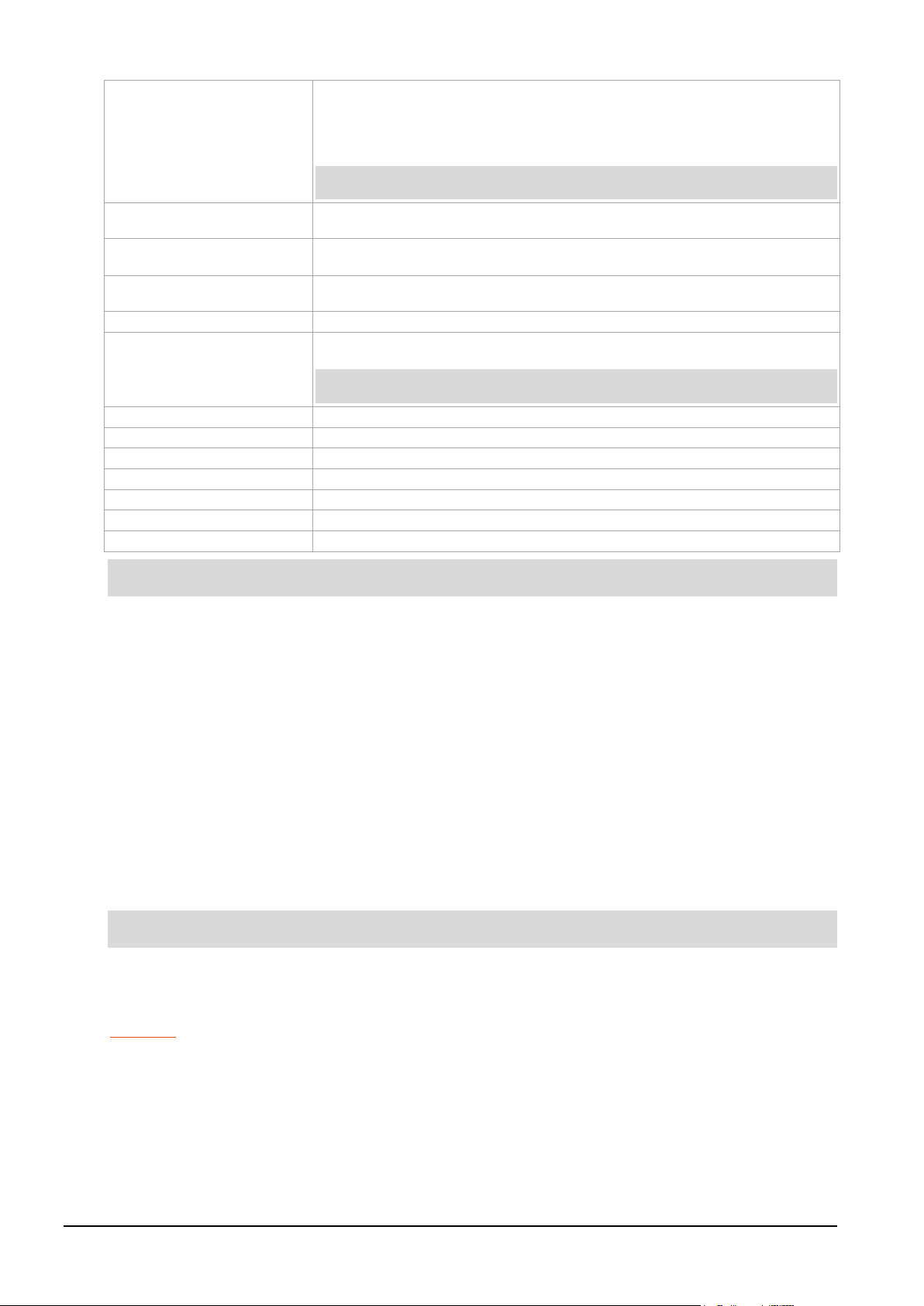
To view the FPGA image revision strings, type the following:
dagrom -dX -x
Where X is the device number of the DAG card you want to configure
factory: d92x2pci_bfs-eth ...
user 1: d92x2pci_bfs-eth...
user 2: d92x2pci_bfs-eth ... (active)
user 3: d92x2pci_bfs-eth ...
User Image 1 will load on power up cycle
Card Serial: 922
Preparing the DAG card for use
Before configuring the DAG card you must run the appropriate dagconfig command to set the default
parameters in the DAG card. This ensures the DAG card functions correctly once you begin capturing
data.
Ensure you do this each time the FPGA is reprogrammed.
dagconfig -dX default
(Where X is the device number of the DAG card you want to configure).
The current DAG 9.2X2 configuration displays and the firmware is verified as correctly loaded. See
dagconfig (page 33
) for more information.
22 ©2010 - 2012 Endace Technology Ltd. Confidential - Version 10 - May 2012
Page 29

EDM01-36v10 DAG_9.2X2_Card_User_Guide - Configuring the DAG card
Note:
DAG card Configuration and Status
Display Current Configuration
Once you have loaded the firmware image you should run the dagconfig tool without arguments to
display the current card configuration and verify the firmware has been loaded correctly.
To display the default configuration for the first card, use:
dagconfig –dX
Where X is the device number of the DAG card you want to configure.
A description of applicable dagconfig tokens follows.
Not all commands are displayed in the following outputs.
Ethernet LAN
Card Information:
Firmware: d92xpci_bfs-eth ... (user 2)
Serial : 8002434
MAC Address A : 00:00:00:00:00:00
MAC Address B : 00:00:00:00:00:00
Port A:
laser tx_crc nic enablea nofcl noeql master 10G lan
Port B:
laser tx_crc nic enableb nofcl noeql master 10G lan
Stream 0: stream_drop_count = 765746
Stream 2: stream_drop_count = 0
...
(output truncated)
Stream 60: stream_drop_count = 0
Stream 62: stream_drop_count = 0
PCI Burst Manager:
PCI-e 2.0 x8 (32Gbs)
buffer_size=1024 rx_streams=32 tx_streams=1 drop nooverlap
Memory Streams:
mem=48:512:48:0:48:0:48:0:48:0:48:0:48:0:48:0:48:0:48:0:0:0:0:0:0:0:0:0:0:0:0:0:0:
0:0:0:0:0:0:0:0:0:0:0:0:0:0:0:0:0:0:0:0:0:0:0:0:0:0:0:0:0:0:0
TERF:
terf_strip32
rx_error_a: off
rx_error_b: off
time_mode: no_time_mode
Hash Load Balancer:
hat=0.0-100.0
©2010 - 2012 Endace Technology Ltd. Confidential - Version 10 - May 2012 23
Page 30

EDM01-36v10 DAG_9.2X2_Card_User_Guide - Configuring the DAG card
Ethernet WAN
Card Information:
Firmware: d92xpci_bfs-eth ... (user 2)
Serial : 8002434
MAC Address A : 00:00:00:00:00:00
MAC Address B : 00:00:00:00:00:00
Port A:
laser tx_crc nic enablea nofcl noeql master 10G wan
Port B:
laser tx_crc nic enableb nofcl noeql master 10G wan
Stream 0: stream_drop_count = 765746
Stream 2: stream_drop_count = 0
...
(output truncated)
Stream 60: stream_drop_count = 0
Stream 62: stream_drop_count = 0
PCI Burst Manager:
PCI-e 2.0 x8 (32Gbs)
buffer_size=1024 rx_streams=32 tx_streams=1 drop nooverlap
Memory Streams:
mem=48:512:48:0:48:0:48:0:48:0:48:0:48:0:48:0:48:0:48:0:0:0:0:0:0:0:0:0:0:0:0:0:0:
0:0:0:0:0:0:0:0:0:0:0:0:0:0:0:0:0:0:0:0:0:0:0:0:0:0:0:0:0:0:0
TERF:
terf_strip32
rx_error_a: off
rx_error_b: off
time_mode: no_time_mode
Hash Load Balancer:
hat=0.0-100.0
24 ©2010 - 2012 Endace Technology Ltd. Confidential - Version 10 - May 2012
Page 31

EDM01-36v10 DAG_9.2X2_Card_User_Guide - Configuring the DAG card
dagconfig tokens
Version information ..................................................................................... 32
Example
Example
Note:
dagconfig tokens explained
1000 .......................................................................................................... 25
10G ............................................................................................................ 25
auto_neg / noauto_neg ............................................................................... 26
buffer_size .................................................................................................. 26
crc32 / nocrc............................................................................................... 26
default ........................................................................................................ 26
drop/nodrop ............................................................................................... 27
enable/disable ............................................................................................. 27
eql/noeql .................................................................................................... 27
eth ............................................................................................................. 27
fcl/nofcl ...................................................................................................... 27
Hash Load Balancer ..................................................................................... 28
lan ............................................................................................................. 28
laser/nolaser ............................................................................................... 28
lock/nolock ................................................................................................. 28
master/slave ............................................................................................... 28
mem .......................................................................................................... 29
nic/nonic .................................................................................................... 29
nodelay ...................................................................................................... 29
overlap/nooverlap ....................................................................................... 30
PCI ............................................................................................................. 30
relative ....................................................................................................... 30
reset .......................................................................................................... 31
rx and tx Streams ........................................................................................ 31
......................................................................................................... 31
rxonly
rxtx ............................................................................................................ 31
stream_drop_count ..................................................................................... 31
terf_strip16/terf_strip32/noterf_strip ............................................................ 31
time_mode ................................................................................................. 32
tx_crc/notx_crc ........................................................................................... 32
txonly ......................................................................................................... 32
txrxerror/notxrxerror ................................................................................... 32
wan ............................................................................................................ 32
1000
Sets the DAG card into 1000BaseTX (1GE) mode.
dagconfig 1000
10G
Sets the DAG card into the 10G receive mode.
dagconfig 10G
10G and lan may be used interchangeably.
©2010 - 2012 Endace Technology Ltd. Confidential - Version 10 - May 2012 25
Page 32

EDM01-36v10 DAG_9.2X2_Card_User_Guide - Configuring the DAG card
Note:
Example
In Linux operating systems
In Window s operating systems
Example
Note:
Note:
Example
auto_neg / noauto_neg
From DAG software 3.1.0 onwards
valid and still can be used.
auto_neg/noauto_neg
nic/nonic
is replaced by
auto_neg/noauto_neg
is not supported by some older cards.
. Both options are
For 1G Ethernet only. The DAG card operates in either “auto_neg” or “noauto_neg” mode.
In
auto_neg mode you must connect the DAG card directly to a Ethernet switch or card with a full-duplex
cable, in which case the DAG card will perform Ethernet auto-negotiation.
The
noauto_neg mode is intended for use with optical fiber splitters. In this mode you must connect the
receive socket of the DAG port to the output of an optical splitter inserted into a network link between
two other devices. The transmit socket of the DAG should be unconnected.
noauto_neg mode, Ethernet auto-negotiation is not performed. This allows you to use one splitter on
In
each DAG receive port to monitor each direction of a full-duplex Ethernet link.
dagconfig auto_neg
dagconfig noauto_neg
buffer_size
The buffer size=nMB indicates the total amount of memory allocated to the DAG card. Memory allocation
occurs at boot time.
dagmem is used to allocate the memory to each installed DAG card. For details on how to allocate
memory, refer to
EDM04-32 dagmem Software Guide
.
Memory is allocated using the DAG Devices tool For details on how to allocate memory, refer to
37 Windows DAG Software Installation Guide
.
EDM04-
For information on calculating the required stream buffer size, see Guidance for stream buffer sizing
(page 71).
crc32 / nocrc
Enables CRC checking on the DAG card which allows detection of corrupted data within the entire frame.
Sets the checking to None or 32 bits.
dagconfig nocrc
dagconfig crc32
Only applicable to 1G Ethernet - Not applicable to 10G Ethernet LAN or WAN.
default
The default command initializes the DAG card configuration and sets all operational settings to the
default network mode values. The command also undoes any user customizations and resets the DAG
card configuration back to its default state.
When you run dagconfig -dX default the
(Where X is the device number of the DAG card you want to configure).
dagclock inputs and outputs are also reset to defaults.
dagconfig -d0 default
26 ©2010 - 2012 Endace Technology Ltd. Confidential - Version 10 - May 2012
Page 33

EDM01-36v10 DAG_9.2X2_Card_User_Guide - Configuring the DAG card
Example
Example
Notes:
Example
Example
Example
drop/nodrop
Determines if the DAG card's memory holes are de-coupled.
In
drop mode, the memory holes are de-coupled. If the data rate on one memory hole slows, the data
rate on any other memory holes is not affected. The dropping of packets occurs at the individual
stream's burst manager.
In
nodrop mode, the memory holes are coupled. The speed of the slowest memory hole determines the
overall speed of the data rate. The dropping of packets occurs at the port.
dagconfig drop
dagconfig nodrop
enable/disable
Sets whether this DAG card captures data on the defined port (a or b).
dagconfig -d0 enablea
dagconfig -d0 disablea
dagconfig -d0 enableb
dagconfig -d0 disableb
•
DAG card ports are enabled by default. You do not need to use
dagconfig
to enable the card in
order to begin capture unless you have previously disabled it.
•
On some firmware images changes to this option may not be applicable.
eql/noeql
Sets or unsets equipment loopback. For testing set to eql mode and normal operation set to noeql
mode.
eql mode loops transmit data from the host back to the PCIe Gen 2.0 bus.
dagconfig eql
dagconfig noeql
eth
Sets framer into ETH receive mode. Image dependent - only operates in Ethernet images
dagconfig eth
fcl/nofcl
Sets or unsets Facility loop back. For testing set to fcl mode and normal operation set to nofcl mode.
FCL retransmits the data received and also send it to the host.
dagconfig fcl
dagconfig nofcl
©2010 - 2012 Endace Technology Ltd. Confidential - Version 10 - May 2012 27
Page 34

EDM01-36v10 DAG_9.2X2_Card_User_Guide - Configuring the DAG card
Example
Note:
Example
Note:
Example
Hash Load Balancer
Hash Load Balancing configuration. Each stream is allocated a percentage of incoming traffic.
hat=x1-x2:x3-x4:..
For further details, refer to
EDM04-31 Enhanced Packet Processing v2
.
lan
Set the DAG card into LAN receive mode.
dagconfig lan
10G and lan may be used interchangeably.
laser/nolaser
Enables/disables the transmit laser for the optical transceivers.
dagconfig laser
dagconfig nolaser
lock/nolock
Read only. Indicates that the card is receiving a signal at the appropriate frequency (lock), or there is no
signal being received (
nolock).
master/slave
Defines whether the data transmitted is clocked with the recovered clock from the input (Slave) or if it
uses the synthesized reference clock on the card (Master).
28 ©2010 - 2012 Endace Technology Ltd. Confidential - Version 10 - May 2012
Page 35

EDM01-36v10 DAG_9.2X2_Card_User_Guide - Configuring the DAG card
Example
Note:
Note:
Examples
Note:
Example
mem
It is possible to split the DAG card's allocated memory between the receive and transmit stream buffers
to suit specific requirements. Where a DAG card does not support transmit, set the transmit stream
buffers to 0 (zero). The split is displayed as a ratio as shown below:
mem=X:Y
where:
X is the memory allocated in MB to the rx stream
Y is the memory allocated in MB to the tx stream. Only applicable if the DAG card supports
transmit.
If there are multiple
mem=X:Y:X:Y:X:Y
rx or tx streams memory can be allocated to each stream:
Buffer_size (page 26) and rx and tx Streams (page 31) are related to mem.
You can split 128MB of memory evenly between the tx and rx streams using:
dagconfig –d0 mem=64:64
You cannot change the stream memory allocations while packet capture or transmission is in progress.
For information on calculating the required stream buffer size, see Guidance for stream buffer sizing
(page 71).
nic/nonic
Modes: 10G Ethernet only.
This token operates very differently from the previous nic/nonic token.
In nic mode, the DAG card must have a receive signal present to transmit packets. The DAG card
transmits the ‘Remote Fault’ ordered set when no signal is present on its receiver (compliant mode).
In
nonic mode this behavior is disabled, allowing the DAG card to transmit packets without having a
receive signal present (non compliant mode).
dagconfig nic
dagconfig nonic
For 1G Ethernet use auto_neg / noauto_neg (page 26)
nodelay
Applicable to TR-TERF. Disables Relative Timed Release mode (No Delay Mode).
In
No Delay Mode
only minimum gaps between packets.
all packets are transmitted at the maximum rate permitted by the line interface, using
See also relative (page 30), time_mode (page 32
).
dagconfig nodelay
©2010 - 2012 Endace Technology Ltd. Confidential - Version 10 - May 2012 29
Page 36

EDM01-36v10 DAG_9.2X2_Card_User_Guide - Configuring the DAG card
Example
Note:
Example
Example
Notes:
overlap/nooverlap
Configures the rx and tx memory hole to be overlapped. This enables in-line forwarding without
copying the data between the stream buffers.
dagconfig overlap
dagconfig nooverlap
This option is only applicable on firmware images containing TX.
For further details refer to
EDM04-04 dagfwddemo User Guide
.
PCI
Describes the following information about the DAG card.
• Bus speed - 1.0, 2.0 or 3.0.
• Number of lanes - x1, x2, x4 or x8.
• Data throughput - dependent on the bus speed and number of lanes.
PCI Burst Manager:
PCI-e 2.0 x8 (32Gbs)
relative
Applicable to TR-TERF - set to Relative Timed Release mode.
In Relative Timed Release Mode, each packet is transmitted according to its timestamp, relative to the
first packet in the transmit stream. This is shown in the following example where Packet A will be
transmitted immediately, Packet B will be transmitted one second later and Packet C will be transmitted
one second after that:
Packet A: Timestamp = 2006-07-24 03:45:55.9720326 UTC
Packet B: Timestamp = 2006-07-24 03:45:56.9720326 UTC
Packet C: Timestamp = 2006-07-24 03:45:57.9720326 UTC
If for any reason the transmission of Packet B is delayed, the module will still attempt to transmit Packet
C two seconds after Packet A. It will do this even if it means reducing the gap between Packet B and
Packet C.
When using multiple output ports in this mode the timing for both ports is maintained. This is shown in
the following example where on port A Packet 4 is transmitted three second after Packet 1 and on port B
Packet 3 is transmitted one second after Packet 2. The Packet 2 is transmitted one second after Packet 1
even when they are send out on independent ports.
Packet 1 (Port A): Timestamp = 2006-07-24 03:45:55.9720326 UTC
Packet 2 (Port B): Timestamp = 2006-07-24 03:45:56.9720326 UTC
Packet 3 (Port B): Timestamp = 2006-07-24 03:45:57.9720326 UTC
Packet 4 (Port A): Timestamp = 2006-07-24 03:45:58.9720326 UTC
See also time_mode (page 32), nodelay (page 29).
dagconfig relative
•
The previous version of Relative Mode was port independent and you will see a different release
pattern transferring old files.
•
The relative placement of the packets is accurate to ± 100ns.
30 ©2010 - 2012 Endace Technology Ltd. Confidential - Version 10 - May 2012
Page 37

EDM01-36v10 DAG_9.2X2_Card_User_Guide - Configuring the DAG card
Example
Example
Example
Note:
Example
Note:
Example
reset
Resets the ethernet framers, set auto mode.
dagconfig -d0 reset
rx and tx Streams
Indicates the number of rx and tx streams are available on the DAG card. Not configurable.
Stream information relates to the setting of mem (page 29
).
rxonly
Configures the memory hole to receive only.
dagconfig rxonly
rxtx
Enables both transmit and receive, and splits the memory hole for rx and tx.
This allocates 16MB of memory to each transmit stream, and divides the remaining memory between the
receive streams.
dagconfig rxtx
This option is only applicable on firmware images containing TX.
stream_drop_count
Details the number of packets dropped during current capture session on this stream.
Stream 0: stream_drop_count = 0
Stream 2: stream_drop_count = 0
...
terf_strip16/terf_strip32/noterf_strip
Strips the CRC value (32 bits) from the packet or sends packet “as is” (noterf_strip). The TERF line in
the current configuration indicates the current TERF option.
Only displayed if the DAG card supports transmit (i.e. has a TERF image).
dagconfig terf_strip32
dagconfig noterf_strip
©2010 - 2012 Endace Technology Ltd. Confidential - Version 10 - May 2012 31
Page 38

EDM01-36v10 DAG_9.2X2_Card_User_Guide - Configuring the DAG card
Example
Example
Example
Notes:
Note:
Example
Example
time_mode
Applicable to TR-TERF.
Sets the time release mode.
nodelay sends packets out with no delay. Shows as no_time_mode.
relative mode sends out packets in the same time spacing as they were received.
See also relative (page 30), nodelay (page 29
).
dagconfig nodelay
dagconfig relative
tx_crc/notx_crc
Modes: Ethernet, WAN only.
Enables the crc(fcs) in the transmitted packets CRC(FCS).
dagconfig tx_crc
dagconfig notx_crc
txonly
Configures the memory hole to transmit only.
dagconfig txonly
•
Only displayed if the DAG card supports transmit (i.e. has a TERF image).
•
This option is only applicable on firmware images containing TX.
txrxerror/notxrxerror
Indicates how to process packets that are transmitted with an RX error flag. Packets are either
discarded
(notxrxerror) on or transmitted (txrxerror).
Only displayed if the DAG card supports transmit (i.e. has a terf image).
dagconfig txrxerror
dagconfig notxrxerror
wan
Set the DAG card into WAN receive mode.
dagconfig wan
Version information
Details the following information about the connected DAG card:
• Firmware image programmed in the FPGA.
• The DAG card serial number.
• The MAC address(s) of the DAG card's ports (Ethernet cards only).
32 ©2010 - 2012 Endace Technology Ltd. Confidential - Version 10 - May 2012
Page 39
EDM01-36v10 DAG_9.2X2_Card_User_Guide - Configuring the DAG card
Notes:
*Warning:
Accessing the -m and -n options simultaneously on the same DAG card may
result in inaccurate results.
-1,--porta
Port A only (default all). Multi-port cards only.
-2,--portb
Port B only (default all). Multi-port cards only.
-3,--portc
Port C only (default all). Four-port cards only.
-4,--portd
Port D only (default all). Four-port cards only.
--porte to --portp
As above, for extra ports on the 3.7T DAG card.
-I, --attribute-index <n>
Gets or sets the attribute for the nth instance of a component with multiple
-G
-c,--concfg <conncfg>
Connection configuration. Used by the DAG 7.1S only.
-C,--counters
Outputs the counters. Verbosity levels from 0=(basic / default) to 3=(full).
-d,--device <device>
DAG device to use. Default is d0.
-e,--extended
Displays the current extended statistics (non boolean and image dependant).
Note:
--framerfirmware <framerfirmware>
DAG 9.2X2 only. Specifies the path to the framer firmware image. Allows
-G,--getattribute
<getattribute>
Gets individual attributes by attribute name. Use in conjunction with the --
-h,--help
Displays the MAN pages. The information displayed is dynamically based on
Note:
-i,--interval <seconds>
Interval to repeat in seconds.
-m,--hmon *
Outputs the hardware monitor information.
-n,--voltages *
Outputs the DAG card voltage monitor information.
--no-default
Do not run default automatically after reset.
-S,--setattribute
<setattribute>=<value>
Sets individual attributes by attribute name. Use in conjunction with the --
-s,--statistics
Outputs the statistics for the DAG card. Verbosity levels from 0=(basic /
-T,--tree
Outputs the supported Configuration and Status attributes and components
-t,--txstats
Outputs the transmit statistics for the DAG card. Where applicable.
-u, --ucounters
Outputs the universal counters for the DAG card. Where applicable.
-v,--verbose <level>
Sets the verbosity level, from 0 (basic) to 3 (full).
-V,--version
Display the DAG card version information.
dagconfig options
dagconfig is a software utility used to configure and display statistics. By default all commands, unless
otherwise defined, run on device 0 (
lists
dagconfig options.
-d0). Commands only apply to one DAG card. The following table
•
•
For DAG cards with more than 2 ports, you can select the required port using: -
port<letter>
.
Not all options listed are applicable to all DAG cards.
Options: Description
instances. Index n starts from 0. Cannot be used in conjunction with --port
options. Used with
or -S options.
port<number>
or --
Verbosity levels from 0=(basic / default) to 3=(full).
Some images may not contain extended statistics.
you to override the default path to the framer firmware.
porta or --portb options to get individual only multi-port cards.
the DAG card and does not work correctly when there is no DAG card in the
system.
There are a few commands that display even though they are not applicable.
porta or --portb options to get individual only multi-port cards.
default) to 3=(full).
with the description and name. Using the -v2 verbosity level also outputs all
components and attribute codes. Verbosity levels from 0=(basic / default) to
3=(full).
©2010 - 2012 Endace Technology Ltd. Confidential - Version 10 - May 2012 33
Page 40
EDM01-36v10 DAG_9.2X2_Card_User_Guide - Configuring the DAG card
Notes:
Port
Indicates the port the status conditions apply to.
Lock
Card is locked to the incoming signal and can capture data.
Link
The link is fully validated.
Loss of Pointer
Loss of pointer. WAN mode only.
Loss of Frame
Indicates oof has been asserted for more than 3ms. WAN mode only.
Lof
Indicates loss of frame. 1GE mode only.
Auto neg complete
Auto negotiation process has completed, Only applicable when using copper transceivers.
Viewing the DAG card status
Interface Status
When you have configured the card according to your specific requirements you can view the interface
statistics to check the status of each of the links using:
dagconfig –dX –s
(Where X is the device number of the DAG card you want to configure).
For more information see dagconfig (page 33
There are multiple printout levels. The statistics displayed below are printout level 0.
).
• 1:
• 0:
• -
condition is present on the link.
condition is not present on the link.
: condition is not applicable.
Condition Definition
1GE only.
34 ©2010 - 2012 Endace Technology Ltd. Confidential - Version 10 - May 2012
Page 41
EDM01-36v10 DAG_9.2X2_Card_User_Guide - Configuring the DAG card
RX_Bytes
Number of payload bytes received from the line.
RX_Frames
Number of packets received from the line.
RX_FCS
Number of packets received from the line with errors (typically FCS errors).
RX_Protocol_Errors
Number of packets received from the line with errors. Errors can be:
type, fsame code, or fsame invalid errors
Port_Drop
Number or packets dropped on the port.
Tx_Bytes
Number of payload bytes transmitted to the line.
Tx_Frames
Number of packets transmitted to the line.
Tx_IF_Drop
(Port 0 or 1). A count of all packets released but not sent on the line.
Tx_ERF_Type_Drop
A count of all Packets in the transferred ERF stream that do not match the
Universal counters
The counters contain details of the number of frames and any errors. The counters are latch and clear
so values indicate the amount of data since the last time the counters were read.
dagconfig –dX –u
(Where X is the device number of the DAG card you want to configure).
For more information see dagconfig
Example outputs are shown:
Ethernet
(page 33).
Counter Definition
FCS, short packet, truncated packet, length field, length
.
The packet is discarded when the DAG card is set to NIC mode and no link has
been established.
target protocol.
Example:
When the transmit ERF stream contains 10 ETH and 10 POS packets and sends
that on a Ethernet Link only the Ethernet packets will be transmitted. The POS
packets are discarded and counted.
©2010 - 2012 Endace Technology Ltd. Confidential - Version 10 - May 2012 35
Page 42
EDM01-36v10 DAG_9.2X2_Card_User_Guide - Configuring the DAG card
Tx_ERF_Interface_Drop
A count of all Packets addressed to a interface that is not supported by the DAG
Tx_ERF_RXError_Drop
A count of packets discarded with an RX_Error flag.
RX_Error
Tx_ERF_MinLen_Drop
Packets in the transferred ERF stream what are either to short or to long are
Tx_IF_Late_Release
When operating in Time-Release mode each packet is transmitted according to
card.
Example:
When transmitting an existing capture file from a four interface DAG card to a
two interface DAG card, all packets for interface 2 and 3 are discarded.
When the DAG card is configured in notxrxerror mode all packets marked
with an
flag are discarded.
Tx_ERF_MaxLen_Drop
discarded before they are released. The amount of discarded packets is shown
in the ERF_minLen and the ERF_MaxLen drop counter.
Example:
For Ethernet the allowed packet size is between 32 and 9616 bytes.
its timestamp. When consecutive packets shall be released at the same time
they have the same timestamp. However, because of the sequential nature of
the stream the second packet is send out after the first packet. This "late"
release is noted by the DAG card and each event increments the late release
counter.
36 ©2010 - 2012 Endace Technology Ltd. Confidential - Version 10 - May 2012
Page 43

EDM01-36v10 DAG_9.2X2_Card_User_Guide - Using your DAG card
Note:
Using your DAG card
Introduction
This chapter describes how to complete the following operations for a DAG card:
• Basic data capture (page 37
Packet Processing v2
.
) - For Enhanced Packet Processing v2 refer to
EDM04-31 Enhanced
• Viewing captured data (page 40)
• Converting captured data (page 43)
• Using third party applications (page 47)
• Transmitting captured data (page 47)
Basic data capture
dagsnap is a software utility used to write to disk the data captured from a DAG card.
Data is collected in Extensible Record Format (ERF) which can then be viewed using
converted to other formats using
dagconvert.
When capturing high speed data Endace recommends you use dagsnap, see Capturing data at high
speed (page 39).
For further information on the software utilities see:
• dagsnap (page 38
)
• dagbits (page 40)
• dagconvert (page 43)
Starting a capture session
dagbits, or
To start the capture session, type the following at the prompt:
dagsnap -dX –v -o tracefile.erf
(Where X is the device number of the DAG card you want to configure).
You can use the -v option to provide user information during a capture session although you may want
to omit it for automated trace runs.
By default, dagsnap runs indefinitely. To stop, use
CTRL+C
. You can also configure dagsnap to run for
a fixed time period then exit.
©2010 - 2012 Endace Technology Ltd. Confidential - Version 10 - May 2012 37
Page 44

EDM01-36v10 DAG_9.2X2_Card_User_Guide - Using your DAG card
Note:
-D, --delay <n>
Delay processing by an extra n milliseconds on each burst.
-d <device >,
Use the DAG device referred to by DEVICE. Supported syntax includes 0, dag1, and
-D <n>, --delay <n>
Delay processing by an extra <n> milliseconds on each burst.
-h, -?,
--help, --usage
Display usage (help) information.
-j,
--maxwrite
Maximize disk writing performance by only writing data to disk in chunks. This option
-m <mebibytes>,
--maxdata <mebibytes>
Write at most <mebibytes > megabytes of data per call to the DAG API (default is 4
-o <filename>
--fname <filename>
Write the captured packets to <filename>, in ERF format (default is standard output).
-s <seconds>
--runtime <seconds>
Run for <seconds>, then exit.
-v
Increase output verbosity. When dagsnap is run with this command three columns of
-V, --version
Display version information.
-w,--wait
<waitseconds>
Delay(wait) in seconds before capture and after the stream is initialized
dagsnap
dagsnap is a data capture software utility.
The following table lists all available options in
dagsnap.
Not all options listed are applicable to all DAG cards.
Option Description
--device <device >
--verbose
/dev/dag3 to refer to DAG cards, and 0:2, dag1:0, and /dev/dag2:0 to refer to specific
streams on cards.
may not be available on all operating systems. Supported in Linux only.
MiB).
data are reported every second. These columns contain:
1. The cumulative total of data written out from the DAG card.
2. The buffer occupancy. Small values indicate no packet loss.
3. The rate at which data is currently being written.
38 ©2010 - 2012 Endace Technology Ltd. Confidential - Version 10 - May 2012
Page 45

EDM01-36v10 DAG_9.2X2_Card_User_Guide - Using your DAG card
Capturing data at high speed
As the DAG card captures packets from the network link, it writes a record for each packet into a buffer
in the host computer’s main memory.
To avoid packet loss, the user application reading the record, such as
dagsnap, must be able to read
records out of the buffer as fast or faster than they arrive. If not the buffer will eventually fill and packet
records will be dropped by the DAG card.
If the user process is writing records to hard disk, it may be necessary to use a faster disk or disk array.
If records are being processed in real-time, a faster host CPU may be required.
When the computer buffer fills the “Data Capture” LED on the card will flash or flicker, or may go OFF
completely.
In Windows no screen message displays to indicate when the buffer is full. Please contact Endace
Customer Support at [email protected] for further information on detecting buffer overflow and
packet loss in Windows.
Detecting packet drops
Once the buffer fills, any new packets arriving will be discarded by the DAG 9.2X2 card until some data is
read out of the buffer to create free space.
You can detect any such losses by observing the Loss Counter (
Format (ERF), or examining the stream drop counters. See Stream drop count (page 31
lctr field) of the Extensible Record
) and Data
Formats (page 65) for more information.
Increasing buffer size
You can increase the size of the host computer buffer to enable it to cope with bursts of high traffic load
on the network link.
For information on increasing the buffer size, see buffer_size (page 26
).
For information on calculating the required stream buffer size, see Guidance for stream buffer sizing
(page 71).
Capturing packets using Enhanced Packet Processing v2
For information on capturing packets using Enhanced Packet Processing v2, refer to
Packet Processing v2
.
EDM04-31 Enhanced
Filtering data
This DAG card uses the dagfilter-loader software with Enhanced Packet Processing v2. For details on
dagfilter-loader, refer to
EDM04-30 dagfilter-loader Software Guide
.
©2010 - 2012 Endace Technology Ltd. Confidential - Version 10 - May 2012 39
Page 46
EDM01-36v10 DAG_9.2X2_Card_User_Guide - Using your DAG card
Notes:
Examples
-0, --stripcrc
ERF records contain no Link-Layer CRCs.
-1, --crc16
ERF records contain 16 bit Link-Layer CRCs (PoS).
-3, --crc32
ERF records contain 32 bit Link-Layer CRCs (PoS and Ethernet).
-a, --atmformat
Set legacy format to ATM (this is the default).
-A, --align <n>
Check the ERF record lengths are multiples of n-bits. To be used with align test
-b, --bigendian
Treat ERF timestamps as big-endian.
-c, --count
Print real-time progress reports as dagbits captures traffic. This is a useful indicator that a
-C
--crcfactor <n>
Sets CRC correction factor for BTX test (0, 16 or 32 bits).
-d
Use the DAG device referred to by <device>. Supported syntax includes 0, dag1, and
-D,
--delay <n>
Introduces a <n> nanosecond delay between processing each record.
-e, --ethformat
Set legacy format to Ethernet (default: ATM).
-E,
Halt operation after a maximum of <n> errors. This option prevents dagbits from creating
-f,
--fname <fname>
Read captured data from <fname>.
-g, --global
Global, causes mono to test for globally increasing rather than per-port timestamps
-H, --steer <n>
Steering control number for steering test, DAG 4.3 and DAG 4.3GE:
-h, -?
--help, --usage
Display usage (help) information.
Viewing captured data
Data captured in ERF format can be viewed with dagbits.
• dagbits
decodes and displays ERF header fields and packet contents are displayed as a Hex dump
only. To decode higher level protocols, Endace recommends using a third party application, see
Using third party applications (page 47).
• dagbits
is also able to run a number of tests, including monotonic time-stamp increment and frame
checksum (FCS, aka CRC) validation.
Test live traffic on dag0, stream 0 for 60 seconds running the lctr, flags and fcs tests:
dagbits -vvc -d0:0 -s60 lctr flags fcs
To read a trace log file using dagbits:
dagbits -vvc print -f logname.log | less
To check for errors in the trace:
dagbits -vvc ltcr flags fcs -f logname.log
For simple decoding of packets:
dagbits -vvc -d0:0 decode | less
If
dagbits reaches the end of the traffic and prints its report then the ERF records were valid.
dagbits
The following table lists all available options in dagbits.
Options Description
test is running correctly.
--device <device>
--haltmax <n>
/dev/dag3 to refer to DAG cards, and 0:2, dag1:1, and /dev/dag2:0 to refer to specific
streams on DAG cards.
extremely large output files when being redirected to a file.
• 0: stream0 force
• 1: test parity
• 2: test CRC
•
3: iface
40 ©2010 - 2012 Endace Technology Ltd. Confidential - Version 10 - May 2012
Page 47

EDM01-36v10 DAG_9.2X2_Card_User_Guide - Using your DAG card
-i
Use "API" interface for live DAG API capture. Possible options are:
-I, --ipf
Assume the ERF contains color information in the pad and offset bytes (for Ethernet ERFs) or
-j,
--jthresh <t>
Set the threshold for the jitter test to <t> microseconds.
-l, --maal <m>
Check for the specified MAAL error code.
-L,
--idle_int <n>
For test idle, interval to detect data is <n>.
-m,
--prnmaxerr <n>
Print the first <n> errored records only, and then continue to count errors silently for the
-n,
--numpkts <n>
Expected number of packets to receive. Returns an error if the actual number is different.
-p, --posformat
Set legacy format to PoS (default: ATM).
-P,
--params <params>
DAG 3.5S capture parameters.
-q, --quiet
Quiet. This instructs dagbits to suppress summary information when terminating. Error
-r, --reclen <n>
Set legacy format record lengths to <n>.
-R, --rlen <n>
When used in conjunction with the rlen test, indicates the RLEN of ERF records to match
-s, --strict
Check for strictly monotonic (increasing) timestamps, rather than monotonic (non-
-S, --stop <n>
Terminate dagbits after <n> seconds of capture. This option only makes sense when
-t,
--haltany <n>
Terminate dagbits if any ERF record type does not match <n>.
-T,
Pause stream for testing purposes where
-u, --count_pad
Count pad records and strictly check -t option.
-U, --maxrec <n>
Process at most <n> records in one pass. This option enables the user to reduce the
dagbits
-v,
Increase verbosity of dagbits. This option increase the amount of data displayed when
-V, --version
Display version information.
-w, --warnings
Instruct dagbits to treat all warnings as errors.
-W, --wlen <n>
When used in conjunction with the wlen test, the wire length of ERF records must be exactly
-X, --wait <n>
Wait before first packet capture from the stream extra n microseconds
-y
--delay_test <n>
Start testing after <n> records have been received
-z, --idlestop
Stop when no traffic is received for one second.
--delta-min
<sec.ms.us.ns>
Delta test minimum timestamp difference - any timestamp difference smaller than the value
--delta-max
<sec.ms.us.ns>
Delta test maximum timestamp difference - any timestamp difference larger than the value
--erase_pad
Erase padding bytes from print function.
--hlb-range <minmax>
Steer hlb (hash load balance) range test range, for example: 15.0-50.0
--no_pad
Turn off pad record flushing.
--api <api>
• 0 DAG 2.4 legacy API interface [dag_offset(3)].
• 1 DAG 2.5 API interface [dag_advance_stream(3)].
• 2 DAG 2.5 API interface [dag_rx_stream_next_record(3)].
HDLC header bytes (for PoS ERFs) and display this information as a packet classification and
destination memory buffer.
duration of the session.
messages are not affected by this option.
against. <n>.
--pause_timing
<x:y:z>
--verbose
decreasing). Affects the behavior of the mono test. With strict checking it is an error for
consecutive timestamps to be equal; they must always increase.
capturing packets from a DAG card (i.e. when used in conjunction with the -d flag).
• x is the delay to start
• y is the period of pause repetition, and
• z is the length of the pause
performance of
printing an ERF record due to the print test or errors in other tests. -v will print payload
contents, -vv will print payload contents and an accompanying ASCII dump of the packet
payload.
NUM bytes.
for various purposes. For live DAG API capture only. See also -D.
will be reported as a failure.
will be reported as a failure.
©2010 - 2012 Endace Technology Ltd. Confidential - Version 10 - May 2012 41
Page 48
EDM01-36v10 DAG_9.2X2_Card_User_Guide - Using your DAG card
--plugin
p2 ... -pn">
Plug-in test to be loaded, including test parameters (p1, p2, etc)
--rxstreams <n>
Number of streams in capture file (for steer -H2).
--stream <n>
Stream number file was captured from (for steer -H2).
--nni
Set ATM network interface to NNI (default UNI).
--tcp_ip_counter
Print TCP Flow and IP Address Counter ERF records.
decode
Decode and print IP, TCP, UDP and ICMP headers.
delta
Print timestamp differences, if used with --delta-min --delta-max, this tests
fcs
Test Frame Check Sum on each ERF frame.
flags
Check and accumulate in-band packet error indications (these are considered to be errors
ipsum
Verify IP checksum.
jitter
Check if timestamp difference variation between consecutive rec pairs is smaller than
lctr
Check and accumulate in-band packet loss indications (not considered an error -- will
mono
Check for monotonically increasing timestamps.
print
Print rec timestamp, CRC, ATM header and payload.
<testname:"-p1 -
See list of tests (page 42) below.
dagbits tests
The following dagbits tests are available for use. Tests not listed in the following table are for Endace
use only.
Test Description
timestamp differences with the provided min/max value.
and return 1).
t/2^32 sec.
return 0).
42 ©2010 - 2012 Endace Technology Ltd. Confidential - Version 10 - May 2012
Page 49

EDM01-36v10 DAG_9.2X2_Card_User_Guide - Using your DAG card
Examples
dag
Read ERF records directly from DAG card (input only).
erf
ERF (Extensible Record Format) file (input and output).
atm
Legacy ATM files (input only).
eth
Legacy Ethernet files (input only).
pos
Legacy PoS files (input only).
null
Produces no input or output.
pcap
pcap(3) format file (input or output).
prt
ASCII text packet dump (output only).
Converting captured data
dagconvert is the software utility that converts captured data from ERF format to PCAP (and other
formats). Once in non ERF format the data can be read using third party applications (page 47
dagconvert can also be used to capture data directly into PCAP format.
To read from DAG card 0 and save to a file in ERF format:
dagconvert -d0 -o outfile.erf
To read from DAG card 0 and save to a file in PCAP format:
dagconvert -d0 -T dag:pcap -o outfile.pcap
To convert a file from ERF format to pcap format:
dagconvert -T erf:pcap -i infile.erf -o outfile.pcap
To convert a file from pcap format to ERF format, ensuring the ERF records are 64-bit aligned (and
therefore suitable for transmission using dagflood):
dagconvert -T pcap:erf -A 8 -i infile.pcap -o outfile64.erf
To capture from DAG card 0 using a BPF filter:
dagconvert -d0 -o outfile.erf -b "host 192.168.0.1 and tcp port 80"
To capture from DAG card 0 using ERF filtering:
dagconvert -d0 -o outfile.erf -f "rx,a"
To capture from DAG card 0 to a series of files of size 128 MB:
dagconvert -d0 -o outfile.erf -r 128m
The first file created is labeled
created. The second is labeled
outfile0000.erf, once the file size reaches 128MB, a second file is
outfile0001.erf etc.
).
dagconvert
dagconvert software utility converts data to various file formats.
Data can be input from a file or captured from a DAG card.
captured from a DAG card to pcap format. This allows the trace file to be used with tools that support
the pcap file format. Also the reverse is possible, where data can be converted to ERF format for use in
other dag utilities.
dagconvert supported input and output formats
dagconvert supports the following input and output formats:
File format Description
dagconvert can be used for converting data
©2010 - 2012 Endace Technology Ltd. Confidential - Version 10 - May 2012 43
Page 50
EDM01-36v10 DAG_9.2X2_Card_User_Guide - Using your DAG card
rx
filter out rx errors (link layer)
ds
filter out ds errors (framing)
trunk
filter out truncated packets
a,b,c,d
filter on indicated interface(s)
pos
(eth -> pos)
ipv4/ipv6
(eth -> ipv4/ipv6)
eth
(ipv4/ipv6 -> eth)
EN10MB
Ethernet
DOCSIS
Ethernet
CHDLC
HDLC
PPP_SERIAL
HDLC
FRELAY
HDLC
MTP2
HDLC
ATM_RFC1483
ATM, AAL5
SUNATM
ATM, AAL5
RAW
IPV4, IPV6
dagconvert supported filters
dagconvert supports the following filters:
Filter Description
dagconvert supported conversion ERF types
dagconvert supports the following conversion EFT types:
ERF Types Description
dagconvert supported DLT types
dagconvert supports the following DLT types (case insensitive):
DLT type Description
44 ©2010 - 2012 Endace Technology Ltd. Confidential - Version 10 - May 2012
Page 51
EDM01-36v10 DAG_9.2X2_Card_User_Guide - Using your DAG card
Note:
-a <api>
Specify which API to use when capturing from DAG cards.
-A <int>
Set the record alignment of the ERF to NUM bytes (ERF only).
-b <BPF>
Specify a tcpdump(1) style BPF (Berkeley Packet Filter) expression to be applied to the
-c 0|16|32
Specify the size (in bits) of the frame checksum (FCS) (pcap(3) only).
-D
Perform defragmentation if possible.
-d <device>
Use the DAG device referred to by DEVICE. Supported syntax includes 0, dag1, and
-E
Strip any extension headers if they exists.
-e <type>
Select the conversion erf type (ERF only).
ETH
-F
Select fixed length output (ERF only).
-f <list>
A comma-delimited list of filters to be applied to the data. Supported filters are:
a,b,c,d
--fnum
Maximum Files before the counter overlaps.
-g,
--sonet-align
Sonet frame alignment for Bit-Level capture files.
-G
Set the GMT offset to NUM seconds (pcap(3) only).
-h, -?, --help,
--usage
Display usage (help) information.
-I
Ignore the first incomplete assemble (in defragmentation).
-i <filename>
Name(s) of the input file(s). If more than one filename is given, the ERF records from the
-o <filename>
Name of the output file.
-p 0|1|2|3
Specifies the interface ID to write into output ERF records
-R
Rename defragmented ERF types, if possible (eg, POS/ATM).
-r N[k|m|g|t]
Rotate the output file after N bytes. Add k (kilobytes), m (megabytes), g (gigabytes) and t
-s <snaplength>
Set the snap length to NUM bytes.
-T <input format>
: <output format>
Input and output types. See the section above for more information about the input and
-t <seconds>
Capture from the DAG card for the defined number of seconds.
-U
Use temporary extension name to indicate current output file. Used with the -r command.
.erf
-u 4|6
Specify the output ERF type IPv4/IPv6 for DLT_RAW when converting pcap DLT_RAW to
dagconvert options
The following is a list of options available in dagconvert.
Not all options are applicable to all DAG cards.
Options Description
• 0: DAG 2.4 legacy API [dag_offset()]
• 1: DAG 2.5 API [dag_advance_stream()](default value)
• 2: DAG 2.5 API [dag_rx_stream_next_record()]
packets.
/dev/dag3 to refer to DAG cards, and 0:2, dag1:1, and /dev/dag2:0 to refer to specific
streams on cards.
• POS (ETH -> POS)
• ipv4/ipv6 (ETH -> ipv4/ipv6)
•
(ipv4/ipv6-> ETH)
• rx Filter out rx errors (link layer).
• ds Filter out ds errors (framing).
• trunc Filter out truncated packets.
•
files will be merged in timestamp order to the output.
To select multiple input files, use this option repeatedly.
The redirection operator '<' can also be used for single file input, provided the input is not of
PCAP format.
Filter on indicated port/interface(s).
(terabytes) suffixes.
output types.
Once a new current outfile is created change the file name extension name to
©2010 - 2012 Endace Technology Ltd. Confidential - Version 10 - May 2012 45
ERF..
.
Page 52

EDM01-36v10 DAG_9.2X2_Card_User_Guide - Using your DAG card
-V
Select variable length output (ERF only)
--version
Display version information.
-v, --verbose
Increase output verbosity.
-y <DLT>
This sets the pcap data link type to be used for BPF filtering (-b) and for pcap output.
Previously only one DLT was mapped to each ERF type.
See above table (page 44) for a list of supported DLT types (case insensitive).
46 ©2010 - 2012 Endace Technology Ltd. Confidential - Version 10 - May 2012
Page 53

EDM01-36v10 DAG_9.2X2_Card_User_Guide - Using your DAG card
Note:
Note:
Using third party applications
Once the captured data is in Pcap format you can use third party applications to examine and process the
data. The third party applications include:
• Wireshark /Tshark (formerly Ethereal /Tethereal)
• TCPDump
• Libpcap
• SNORT
• Winpcap, etc.
For further details refer to
EDM04-21 Libpcap and Third party applications
.
Wireshark/Tshark can also read ERF formatted data directly. This provides more information than
converting to pcap format.
Transmitting captured data
To transmit data out of the DAG 9.2X2 you can used either the DAG API or dagflood.
Configuration
To configure the DAG 9.2X2 card for transmission, you must allocate some memory to a transmit stream.
For details on how to allocate memory see the dagconfig mem (page 29
dagflood User Manual
.
) token and refer to
EDM04-03
You can capture packets at the same time as transmitting packets, using DAG capture tools such as
dagsnap, dagconvert, and dagbits.
You cannot change the stream memory allocations while packet capture or transmission is in progress.
Explicit packet transmission
The operating system does not recognize the DAG 9.2X2 card as a network interface and will not respond
to ARP, ping, or router discovery protocols.
The DAG 9.2X2 card will only transmit packets that are explicitly provided by the user. This allows you to
use the DAG 9.2X2 card as a simple traffic load generator.
You can also use it to retransmit previously recorded packet traces. The packet trace can be either
• transmitted as fast as possible.
• transmitted with the original time intervals between packets (Timed Release TERF (TR-TERF))
• transmitted with the original time intervals between packets and with a specific start time (Triggered
Timed Release TERF (TR-TERF)).
For further details, refer to
EDM04-03 dagflood User Manual
.
©2010 - 2012 Endace Technology Ltd. Confidential - Version 10 - May 2012 47
Page 54

EDM01-36v10 DAG_9.2X2_Card_User_Guide - Using your DAG card
Situation 1 (Ethernet)
Example
Trace files
You can use dagflood to transmit ERF format trace files, providing the files contain only ERF records of
the type matching the current link configuration.
For detailed information on using
dagflood, refer the
EDM04-03 dagflood User Manual
.
When you use DAG cards with multiple ports, ensure all ports referred to by the trace file are active.
This ensures the
dagflood traffic is not blocked when trying to delivering data to an inactive port.
Check the interface status output for the DAG card and ensure the link status for all required destination
ports is active. See Viewing the DAG card statistics. (page 34
For further information on using dagflood please refer to the
)
EDM04-03 dagflood User Manual
available
from Endace Customer Support at https://support.endace.com/.
In addition the length of the ERF records to be transmitted must be a multiple of 64-bits. You can
configure this when capturing packets for later transmission by setting 64-bit alignment using the
dagconfig align64 command.
If packets have been captured without using the
they can be transmitted by using dagconvert (page 43
dagconvert -v -i tracefile.erf -o tracefile.erf -A8
align64 option you can convert the trace files so that
) as shown below:
Alternatively if you are unsure if a trace file is 64-bit aligned you can test the file using dagbits (page 40
as shown below:
dagbits -v align64 -f tracefile.erf
If you do not have any ERF trace files available, you can use
daggen to generate trace files containing
simple traffic patterns. This allows the DAG 9.2X2 card to be used as a test traffic generator.
For further information on using daggen please refer to the
EDM04-06 Daggen User Guide
available from
Endace Customer Support at https://support.endace.com/.
)
TR TERF
For a description, see Timed Release TERF (TR-TERF) (page 7).
Selectable CRC length
TR-TERF can be optionally configured to strip the CRC of an incoming ERF stream, to allow the
retransmitted stream to calculate and add a CRC. There are some situations where this option may be
useful.
The ERF stream was generated without a CRC.
In this case, you should configure TR-TERF not to strip the last 32 bits of the packet as there is no CRC
in place, and configure the MAC to add a hardware-calculated CRC. This has the effect of reducing the
burden of calculating a CRC in the software.
dagconfig noterf_strip tx_crc
48 ©2010 - 2012 Endace Technology Ltd. Confidential - Version 10 - May 2012
Page 55

EDM01-36v10 DAG_9.2X2_Card_User_Guide - Using your DAG card
Situation 2 (Ethernet)
Example
Situation 3 (Ethernet)
Example
The ERF stream was generated with a CRC but the CRC must be corrected on the retransmitted packet.
In this case you should configure TR-TERF to strip the original 32-bit CRC and configure the MAC to add
a hardware calculated CRC as in Situation 1 above to replace it. This means even if the CRC is incorrect
in the received ERF stream, a correct CRC will be generated when the packet is retransmitted.
dagconfig terf_strip32 tx_crc
The ERF stream was generated with a CRC, and the CRC must be retransmitted exactly even if it is
incorrect.
In this case you should configure TR-TERF not to strip the CRC, and configure the MAC not to add a
hardware-calculated CRC, so that the original CRC is retained. This allows received packets with bad
CRCs to be retransmitted which may be a useful tool for testing or diagnostic purposes.
dagconfig noterf_strip notx_crc
Retransmitting errored packets
In some circumstances it may not be desirable to retransmit packets which have been incorrectly
received for any reason. To allow for this, TR-TERF can be optionally configured not to retransmit any
packets marked with the
For further details, refer to
rxerror (receive error) flag.
EDM04-03 dagflood User Manual
.
Usage notes
The following points should be noted when using TR-TERF:
• When using
dagflood to transmit an ERF stream to the card you should set the "-1" flag (maximum
data burst length) to a value greater than the default of 1MB to achieve the highest transmit data
rate. During testing Endace found a value of 16MB (16777216) to be effective. This reduces the
possibility of a buffer under-run occurring if insufficient data is committed in a burst and the
dagflood process is not scheduled by the OS to run in a timely manner.
• For best accuracy when testing, you should ensure both the sending and receiving cards are
synchronized to the same time source.
TR TERF known issues
TR-TERF is less accurate when using multiple interfaces. If a large packet is transmitted to the card on a
particular interface, the transmit buffers for the other interfaces may experience a buffer under-run. This
is because data is only transferred to one interface at any one time, record by record as the input ERF
stream is interleaved between interfaces.
This may be especially noticeable where very small packets are transmitted on one interface and very
large packets transmitted on another interface.
©2010 - 2012 Endace Technology Ltd. Confidential - Version 10 - May 2012 49
Page 56

Page 57

EDM01-36v10 DAG_9.2X2_Card_User_Guide - Synchronizing clock time
Synchronizing clock time
Overview
The core of the DAG synchronization capability is known as the DAG Universal Clock Kit (DUCK).
DAG cards have sophisticated time synchronization capabilities. This allows for high quality timestamps
and optional synchronization to an external time standard.
A clock in each DAG card runs independently from the computer clock. The DAG card’s clock is initialized
using the computer clock, and then free-runs using a crystal oscillator.
Each DAG card's clock can vary relative to a computer clock, or other DAG cards.
DUCK configuration
The DUCK (DAG Universal Clock Kit) is designed to reduce time variance between sets of DAG cards or
between DAG cards and coordinated universal time [UTC].
You can obtain an accurate time reference by connecting an external clock to the DAG card using the
time synchronization connector. Alternatively you can use the host computer's clock in software as a
reference source without any additional hardware.
Each DAG card can also output a clock signal for use by other DAG cards.
Common synchronization
The DAG card time synchronization connector supports a Pulse-Per-Second (PPS) input signal, using RS422 signaling levels.
Common synchronization sources include GPS or CDMA (cellular telephone) or a single DAG card as a
Time Reference Source.
Endace also provides several Time Distribution Servers that provide timing synchronization over multiple
DAG cards. Currently the available Time Distribution Servers include:
• TDS 2 - for further information, refer to
• TDS 6 - for further information, refer to
• TDS 24 - for further information, refer to
For more information on the Time Distribution Server, refer to the
http://www.endace.com.
IRIG-B
For information on synchronizing the DAG 9.2X2 with an IRIG-B device, please refer to
dag_irigb Software Guide
.
EDM05-01 Time Distribution Server User Guide
EDM05-01 Time Distribution Server User Guide
EDM05-02 TDS 24 Installation Guide
Accessories
.
section at
EDM04-33
.
.
©2010 - 2012 Endace Technology Ltd. Confidential - Version 10 - May 2012 51
Page 58

EDM01-36v10 DAG_9.2X2_Card_User_Guide - Synchronizing clock time
Network Time Protocol
NTP (Network Time Protocol) can be used to synchronize a computer clock to a network based reference.
When the NTP daemon starts, it exchanges packets with network time servers to establish the correct
time. If the computer clock is significantly different, the NTP can adjust the computer clock in a single
large 'step'. Over time, NTP adjusts the rate of computer clock to minimize the offset from its reference.
It can take several days for NTP to fully synchronize the computer clock.
The DAG card clock is initialized from the computer's clock rather than from the NTP. Using NTP to
synchronize the computer's clock ensures the DAG card clock remains accurate.
DAG cards can also be synchronized to external references such as GPS or to the computer clock directly.
In both cases the computer clock time is loaded onto the DAG clock when the DAG card is started
dagload, dagreset, dagrom -p).
(
When clock synchronization is enabled, the DAG card time is compared to the computer time once per
second, regardless of the synchronization source. If the times differ by more than 1 second, the DAG
card clock is reloaded from the computer clock and synchronization is restarted. For this reason, the
computer clock should be maintained with better than 1 second accuracy.
If the DAG card clock is synchronized to the computer clock, then small 'step' adjustments of the
computer clock by the NTP daemon can cause the DAG driver to emit warning messages to the console
and system log files if the adjustment exceeds the warning threshold. These messages are intended to
allow the user to monitor the quality of the clock synchronization over time.
The best synchronization is achieved when the DAG card is synchronized to an external GPS reference
clock, and the computer clock is synchronized to a local NTP server.
52 ©2010 - 2012 Endace Technology Ltd. Confidential - Version 10 - May 2012
Page 59

EDM01-36v10 DAG_9.2X2_Card_User_Guide - Synchronizing clock time
Timestamps
ERF files contain a hardware generated timestamp of each packet’s arrival.
The format of this timestamp is a single little-endian 64-bit fixed point number, representing the number
of seconds since midnight on the 1
The high 32-bits contain the integer number of seconds, while the lower 32-bits contain the binary
fraction of the second. This allows an ultimate resolution of 2
st
January 1970.
-32
seconds, or approximately 233
picoseconds.
Different DAG cards have different actual resolutions. This is accommodated by the lower most bits that
are not active being set to zero. In this way the interpretation of the timestamp does not need to change
when higher resolution clock hardware is available. The DAG 9.2X2 implements the 28 most significant
bits which provides a time resolution of 7.5 nanoseconds.
The ERF timestamp allows you to find the difference between two timestamps using a single 64-bit
subtraction. You do not need to check for overflows between the two halves of the structure as you
would need to do when comparing Unix time structures.
Example
Below is example code showing how a 64-bit ERF timestamp (erfts) can be converted into a struct
timeval representation (tv):
unsigned long long lts;
struct timeval tv;
lts = erfts;
tv.tv_sec = lts >> 32;
lts = ((lts & 0xffffffffULL) * 1000 * 1000);
lts += (lts & 0x80000000ULL) << 1; /* rounding */
tv.tv_usec = lts >> 32;
if(tv.tv_usec >= 1000000) {
tv.tv_usec -= 1000000;
tv.tv_sec += 1;
}
©2010 - 2012 Endace Technology Ltd. Confidential - Version 10 - May 2012 53
Page 60

EDM01-36v10 DAG_9.2X2_Card_User_Guide - Synchronizing clock time
Note:
Readable DUCK
The DAG 9.2X2 firmware images allow the user to read the current time directly from the DUCK clock.
This can be useful for verifying clock synchronization.
To check if a firmware image supports reading the DAG clock time, check if the output from the following
command includes the information about the
The factory firmware may not support the DUCK Reader. Please ensure you load the current release
firmware onto the DAG card first, see Configuring the DAG card (page 15).
Command:
daginf -d0 -v
Reading the current DAG time
You can read the current DAG time using dagconfig, using the following command:
Command:
dagconfig -G duck_timestamp
Output:
DUCK Reader version.
duck_timestamp = 2009-07-07 1:33:31.657349680 UTC
The current time is also available programmatically via the DAG Configuration and Status API.
The time-stamp format that the DUCK provides represents time as a single 64-bit fixed point number,
representing seconds since midnight on January 1, 1970. The returned value can also be converted into
a struct timeval representation. For more information refer to
Overview
.
EDM04-34 Configuration & Status API
Performance
Reading the current DAG time requires reading hardware registers on the DAG card over the PCIe Gen
2.0 bus. This operation can take several microseconds to complete.
The DAG clock should not be read at high rates, for example after receiving or sending each packet. The
additional PCIe Gen 2.0 bus accesses from reading the current time may affect packet
capture/transmission performance if performed more than 1000 times per second.
54 ©2010 - 2012 Endace Technology Ltd. Confidential - Version 10 - May 2012
Page 61
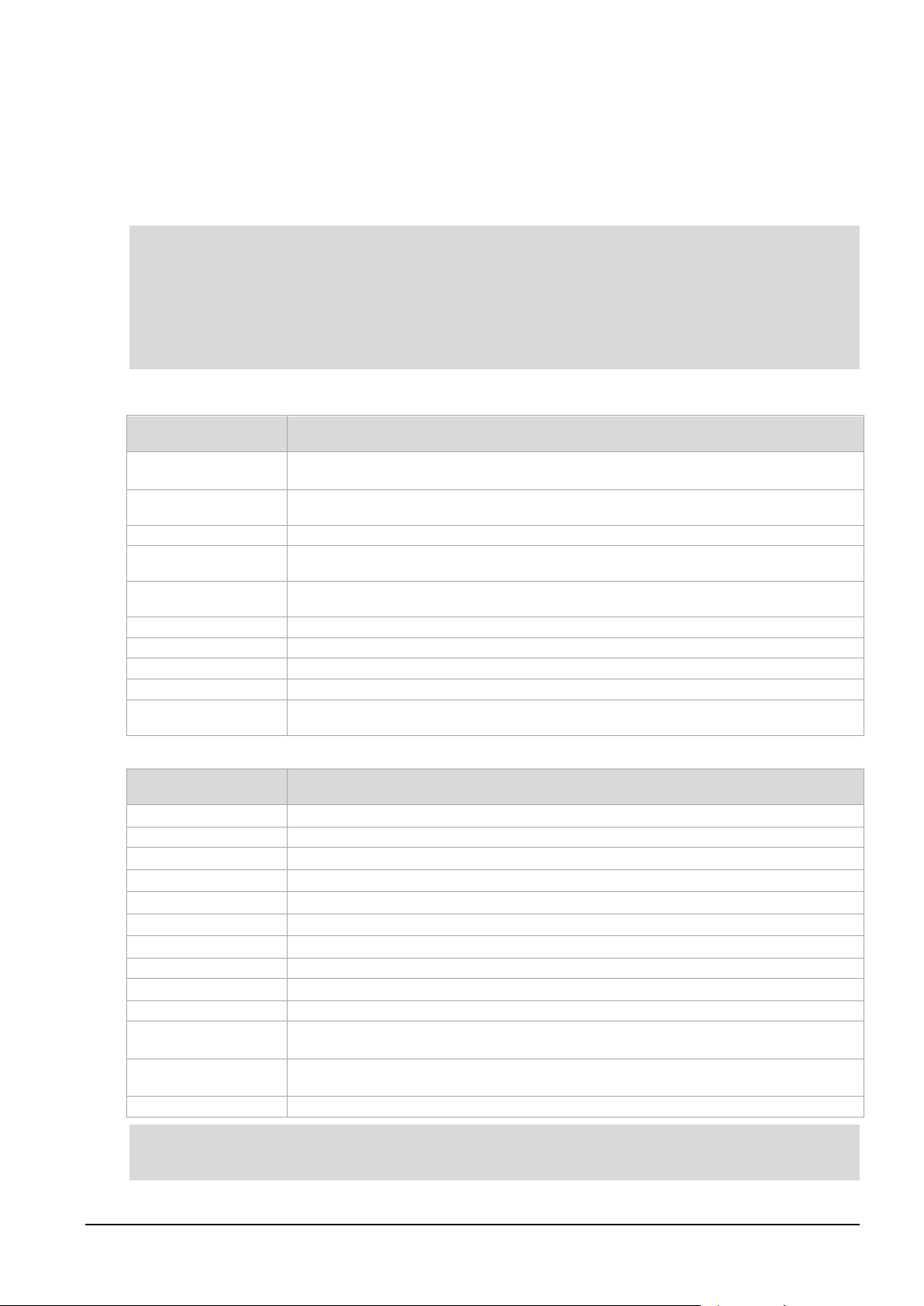
EDM01-36v10 DAG_9.2X2_Card_User_Guide - Synchronizing clock time
Notes:
-d,
--device <device>
Use the DAG device referred to by DEVICE. Supported syntax includes 0, dag1, and
-?,--usage
-h,--help
Display the information on this page
-k,--sync
Wait for DUCK synchronization before exiting
-K,--timeout
<timeout>
Set the synchronization timeout in seconds (default is 60 seconds)
-l,--threshold
<threshold>
Set the Health threshold in nanoseconds. (default is 596ns)
-m,--monitor
Monitors the dagclock's health and displays results each second.
-p,--phase <phase>
Sets the phase correction in ns. The default is 0ns.
-v, --verbose
Increase output verbosity
-V, --version
Display version information
-x
--clearstats
Clears the dagclock statistics.
Options
default
Set the dagclock input and output to RS422 in and none out.
none
Clears the input and output settings.
rs422in
Sets the dagclock input to RS422.
hostin
Sets the dagclock input to Host (unused)
overin
Sets the dagclock input to Internal input (i.e. synchronise to host clock)
auxin
Sets the dagclock input to Auxiliary input (unused)
rs422out
Sets the dagclock output to repeat the RS422 input signal
loop
Output the selected input
hostout
Sets the dagclock output to host (unused)
overout
Internal output (master card)
set
Sets the DAG card's clock to computer clock time and clears clock statistics. The DAG card
reset
Full clock reset. Load time from computer, set RS422in, none out. Clears clock statistics.
sync
Wait for duck to sync before exiting.
Note:
Dagclock
The DUCK is very flexible and can be used with or without an external time reference. It can accept
synchronization from one of several input sources and also be made to drive its synchronization output
from one of several sources.
Synchronization settings are controlled by the
•
You should only run
dagclock
after you have loaded the appropriate FPGA images. If at any stage
you reload the FPGA images you must rerun
•
When you run
dagconfig -d0 default
dagclock utility.
dagclock
the
dagclock
to restore the configuration.
inputs and outputs are also reset to
defaults.
•
By default, all DAG cards listen for synchronization signals on their RS-422 port, and do not output
any signal to that port.
A description of each argument is shown below:
Option Description
/dev/dag3 to refer to DAG cards.
Command Description
takes approximately 20 to 30 seconds to re-synchronize.
The DAG card takes approximately 20 to 30 seconds to re-synchronize.
By default, all DAG cards listen for synchronization signals on their RS-422 port, and do not output any
signals to that port.
©2010 - 2012 Endace Technology Ltd. Confidential - Version 10 - May 2012 55
Page 62

EDM01-36v10 DAG_9.2X2_Card_User_Guide - Synchronizing clock time
Example
Note:
Note:
Dagclock statistics reset
Statistics are reset to zero when the following occur:
• Loading a DAG driver
• Loading firmware
dagclock with a -x option
•
dagclock with a set or reset command.
•
To view the default dagclock configuration:
dagclock –dX
(Where X is the device number of the DAG card you want to configure).
The following is the output from DAG card that has its clock reference connected. The clock statistics
have been reset since the card was last synchronized.
Values differ for each DAG card type.
muxin rs422
muxout none
status Synchronised Threshold 596ns Failures 0 Resyncs 0
error Freq -30ppb Phase -60ns Worst Freq 75ppb Worst Phase 104ns
crystal Actual 100000028Hz Synthesized 67108864Hz
input Total 3765 Bad 0 Singles Missed 5 Longest Sequence Missed 1
start Thu Apr 28 13:32:45 2007
host Thu Apr 28 14:35:35 2007
dag Thu Apr 28 14:35:35 2007
For a description of the
dagclock
output see Dagclock output explained (page 57).
56 ©2010 - 2012 Endace Technology Ltd. Confidential - Version 10 - May 2012
Page 63

EDM01-36v10 DAG_9.2X2_Card_User_Guide - Synchronizing clock time
Muxin
Example
Muxout
Example
Status
Synchronised /
This indicates whether this DAG card is synchronized to the time source listed (Muxin).
Threshold
This is the value above which the DAG card port is considered Not Synchronised.
dagclock -l
Failures
This is a count of the number of times the DAG card has become Not Synchronised.
Resyncs
This is a count of the number of times the DAG card Phase error has exceeded 1 second. See
Example
Error
Freq
An estimate of the synthesized frequency error over the last second in parts per billion.
Phase
The difference between the DAG card's clock and the reference clock at the last time pulse.
Worst Freq
Highest absolute value of the Frequency error since statistic collection began. Reset to zero
Worst Phase
Highest absolute value of the Phase error since statistic collection began. Reset to zero when
Example
Dagclock output explained
Lists the dagclock time input source for this DAG card. The options are RS422in, Hostin, Overin or
Auxin.
muxin rs422
Lists the dagclock time output source for this DAG card. The options are RS422out, Hostout,
Overout or Loop.
muxout none
This line reports on the status of the DAG card.
Output Description
Not
synchronised
The DAG card becomes Synchronised when the absolute Phase error (page 57) is within
the Threshold value for 10 consecutive seconds.
The DAG card becomes Not Synchronised when the absolute Phase error (page 57) is
above the Threshold value for 10 consecutive seconds.
The Threshold value changes depending on the type of input time synchronization. The
defaults are:
• 596 for RS422 synchronization
• 12000 for host synchronization (Unix)
• 50000 for host synchronization (Windows)
This value can be adjusted using the
Error (page 57).
If the DAG card is Not Synchronised for more than 10 seconds the DAG card automatically
runs the following command to update the time on the DAG card:
dagclock -dX set
(Where X is the device number of the DAG card you want to configure).
status Synchronised Threshold 596ns Failures 0 Resyncs 0
This line reports on the synthesized frequency of the DAG card.
option.
Output Description
when statistics are reset, see Dagclock Statistics reset (page 56).
statistics are reset, see Dagclock Statistics reset. (page 56)
©2010 - 2012 Endace Technology Ltd. Confidential - Version 10 - May 2012 57
error Freq -30ppb Phase -60ns Worst Freq 75ppb Worst Phase 104ns
Page 64
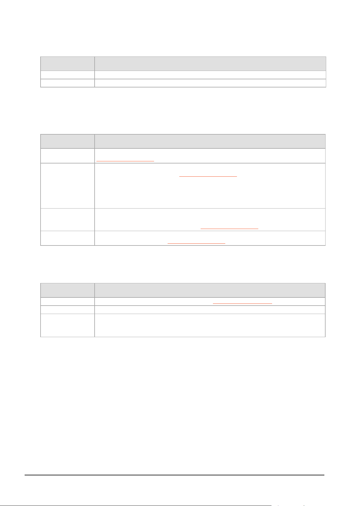
EDM01-36v10 DAG_9.2X2_Card_User_Guide - Synchronizing clock time
Crystal
Actual
The DAG card's crystal frequency calculated based on the reference clock.
Synthesized
The target time stamping frequency. Different for each DAG card type.
Example
Input
Total
The total number of time pulses received. Reset to zero when statistics are reset, see
Bad
The number of time pulses that were rejected (considered Bad) by the DAG card. Reset to
Singles missed
The number of times a single time pulse failed to be received by the DAG card (i.e. a two
Longest
Sequence Missed
This displays the longest time gap (in seconds) between a pair of time pulses. Reset to zero
Example
Start / Host / DAG
Start
This is the time statistics collection started. See Dagclock Statistics reset. (page 56)
Host
Current Host (computer) time.
DAG
The DAG card time at the last time pulse. If the DAG card has never been synchronized, the
No active input - free running.
Example
This line reports on the DAG card crystal oscillator.
Output Description
crystal Actual 100000028Hz Synthesized 67108864Hz
This line reports on the time pulses received by the DAG card.
Output Description
Dagclock Statistics reset (page 56).
zero when statistics are reset, see Dagclock Statistics reset (page 56).
When the DAG card is Synchronised a time pulse is considered Bad if it exceeds the
Threshold.
Time pulses are considered Bad if they were not received 1 second (approximately) after the
last time pulse. This may be caused by noise.
second gap).
Reset to zero when statistics are reset, see Dagclock Statistics reset (page 56).
when statistics are reset, see Dagclock Statistics reset (page 56).
input Total 3765 Bad 0 Singles Missed 5 Longest Sequence Missed 1
Output Description
following displays:
start Thu Apr 28 13:32:45 2007
host Thu Apr 28 14:35:35 2007
dag Thu Apr 28 14:35:35 2007
58 ©2010 - 2012 Endace Technology Ltd. Confidential - Version 10 - May 2012
Page 65

EDM01-36v10 DAG_9.2X2_Card_User_Guide - Synchronizing clock time
Warning:
Never connect a DAG card or the Time Distribution Server to active Ethernet
equipment or telephone equipment.
Card with timing reference
Overview
To obtain the best timestamp accuracy you should connect the DAG card to an external clock reference,
such as a GPS or CDMA time receiver.
To use an external clock reference source, the host computer’s clock must be accurate to UTC to within
one second. This is used to initialize the DUCK.
When the external time reference source is connected to the DAG card time synchronization connector,
the DAG card automatically synchronizes to a valid signal.
Pulse signal from external source
The time synchronization connector supports both RS-422 (PPS) and IRIG-B (only some DAG cards)
signals from an external source. This is derived directly from an external reference source or distributed
through the Endace Time Distribution Server which allows two or more DAG cards to use a single Time
Reference Source. For details on the available Time Distribution Server see Common Synchronization
(page 51).
Synchronize to an external source as follows:
dagclock –dX
(Where X is the device number of the DAG card you want to configure).
Output:
muxin rs422
muxout none
status Synchronised Threshold 596ns Failures 0 Resyncs 0
error Freq 30ppb Phase -15ns Worst Freq 238ppb Worst Phase 326ns
crystal Actual 100000023Hz Synthesized 67108864Hz
input Total 225 Bad 0 Singles Missed 1 Longest Sequence Missed 1
start Thu Apr 28 14:55:20 2007
host Thu Apr 28 14:59:06 2007
dag Thu Apr 28 14:59:06 2007
Testing the signal
For Linux and FreeBSD, when a synchronization source is connected the driver outputs messages to the
console log file
To test the signal is being received correctly and has the correct polarity use the
dagpps –dX
(Where X is the device number of the DAG card you want to configure).
dagpps measures the input state many times over several seconds, displaying the polarity and length of
input pulse.
/var/log/messages.
dagpps tool as follows:
©2010 - 2012 Endace Technology Ltd. Confidential - Version 10 - May 2012 59
Page 66

EDM01-36v10 DAG_9.2X2_Card_User_Guide - Synchronizing clock time
Single card no reference
When a single DAG card is used with no external reference, the DAG card can be synchronized to the
host computer clock. Most computer clocks are not very accurate by themselves, but the DUCK drifts
smoothly at the same rate as the computer clock.
The synchronization achieved with this method is not as accurate as using an external reference source
such as GPS.
The DUCK clock is synchronized to a computer clock by setting input synchronization selector to overflow
as follows:
dagclock –dX none overin
(Where X is the device number of the DAG card you want to configure).
Output:
muxin overin
muxout none
status Synchronised Threshold 11921ns Failures 0 Resyncs 0
error Freq 1836ppb Phase 605ns Worst Freq 147ppb Worst Phase 324ns
crystal Actual 49999347Hz Synthesized 16777216Hz
input Total 87039 Bad 0 Singles Missed 0 Longest Sequence Missed 0
start Wed Apr 27 14:27:41 2007
host Thu Apr 28 14:38:20 2007
dag Thu Apr 28 14:38:20 2007
60 ©2010 - 2012 Endace Technology Ltd. Confidential - Version 10 - May 2012
Page 67

EDM01-36v10 DAG_9.2X2_Card_User_Guide - Synchronizing clock time
Note:
Note:
Two cards no reference
Overview
If you are using two DAG cards in a single host computer with no reference clock, you must synchronize
the DAG cards using the same method if you wish to compare the timestamps between the two DAG
cards. You may wish to do this for example if the two DAG cards monitor different directions of a single
full-duplex link. You can synchronize the DAG cards in two ways:
• One DAG card can be a clock master for the second. This is useful if you want both DAG cards to be
accurately synchronized with each other, but not so for absolute time of packet time-stamps, or
• One DAG card can synchronize to the host and also act as a master for the second DAG card.
Synchronizing with each other
Although the master DAG card’s clock drifts against UTC, the DAG cards will be locked together. This is
achieved by connecting the time synchronization connectors of both DAG cards using a DUCK crossover
cable (page 62) - a 4-pin to RJ45 Adapter may be required.
Configure one of the DAG cards as the master so that the other defaults to being a slave as follows:
dagclock –dX none overout
(Where X is the device number of the DAG card you want to configure).
Output:
muxin none
muxout over
status Not Synchronised Threshold 596ns Failures 0 Resyncs 0
error Freq 0ppb Phase 0ns Worst Freq 213ppb Worst Phase 251ns
crystal Actual 100000000Hz Synthesized 67108864Hz
input Total 0 Bad 0 Singles Missed 0 Longest Sequence Missed 0
start Thu Apr 28 14:48:34 2007
host Thu Apr 28 14:48:34 2007
dag No active input - Free running
The slave DAG card configuration is not shown as the default configuration will work.
Synchronizing with host
To prevent the DAG card clock time-stamps drifting against UTC, the master DAG card can be
synchronized to the host computer’s clock which in turn utilizes NTP. This provides a master signal to the
slave DAG card.
Configure one DAG card to synchronize to the computer clock and output a RS-422 synchronization signal
to the second DAG card as follows:
dagclock –dX none overin overout
(Where X is the device number of the DAG card you want to configure).
Output:
muxin over
muxout over
status Synchronised Threshold 11921ns Failures 0 Resyncs 0
error Freq -691ppb Phase -394ns Worst Freq 147ppb Worst Phase 424ns
crystal Actual 49999354Hz Synthesized 16777216Hz
input Total 87464 Bad 0 Singles Missed 0 Longest Sequence Missed 0
start Wed Apr 27 14:27:41 2007
host Thu Apr 28 14:59:14 2007
dag Thu Apr 28 14:59:14 2007
The slave DAG card configuration is not shown, the default configuration is sufficient.
©2010 - 2012 Endace Technology Ltd. Confidential - Version 10 - May 2012 61
Page 68

EDM01-36v10 DAG_9.2X2_Card_User_Guide - Synchronizing clock time
1.
PPS- Out
2.
PPS+ Out
3.
PPS- In
4.
PPS+ In
Note:
TX PPS+
1 3 RX PPS+
TX PPS-
2 6 RX PPS-
RX PPS+
3 1 TX PPS+
RX SERIAL+
4 7 TX SERIAL+
RX SERIAL-
5 8 TX SERIAL-
RX PPS-
6 2 TX PPS-
TX SERIAL+
7 4 RX SERIAL+
TX SERIAL-
8 5 RX SERIAL-
Note:
Connector
Overview
DAG cards have a 4-pin connector for time synchronization. The connector has one bi-directional RS422
differential circuit, A. The Pulse Per Second (PPS) signal is carried on circuit A.
Pin assignments
The 4-pin connector pin assignments and plugs and sockets are shown below:
Normally, you connect the GPS input to the PPS (A) channel input (pins 3 and 4).
The DAG card can also output a synchronization pulse for use when synchronizing two DAG cards, (i.e.
without a GPS input). The synchronization pulse is output on the Out PPS channel (pins 1 and 2).
To connect two DAG cards, use a DUCK crossover cable (page 62
) to connect the two time
synchronization sockets.
The DAG card is supplied with a 4-pin to RJ45 adapter.
DUCK crossover cable
To synchronize two DAG cards together use a cable with RJ45 plugs and the following wiring.
This wiring is the same as an Ethernet crossover cable (Gigabit crossover, All four pairs crossed).
62 ©2010 - 2012 Endace Technology Ltd. Confidential - Version 10 - May 2012
Page 69
EDM01-36v10 DAG_9.2X2_Card_User_Guide - Synchronizing clock time
1
PPS Out+
2
2
PPS Out-
1
3
PPS In+
4
6
PPS In-
3
4-pin to RJ45 adapter
A 4-pin (plug) to RJ45 (socket) adapter is supplied with your DAG card. This adapter allows you to plug a
standard Ethernet RJ45 PPS signal cable into your DAG card. The 4-pin to RJ45 adaptor pin assignments
are shown below:
RJ45 socket Signal name 4 Pin plug
©2010 - 2012 Endace Technology Ltd. Confidential - Version 10 - May 2012 63
Page 70

Page 71

EDM01-36v10 DAG_9.2X2_Card_User_Guide - Data formats
TYPE_ETH
Data formats
Overview
The DAG Card produces trace files in its own native format called ERF (Extensible Record Format). The
ERF type depends upon the type of connection you are using to capture data.
The DAG 9.2X2 supports the following ERF Types:
ERF Type Description
2
An ERF file contains a series of ERF records, with each record describing one packet. An ERF file consists
only of ERF records, and has no file header or trailer. This allows for simple concatenation and splitting of
files to be performed on ERF record boundaries.
ERF records have generic headers, and optional extension headers. The DAG 9.2X2 does not by default
provide extension headers to the user.
For information on other ERF types, please refer to
Ethernet Variable Length Record
EDM11-01 ERF Types
.
©2010 - 2012 Endace Technology Ltd. Confidential - Version 10 - May 2012 65
Page 72
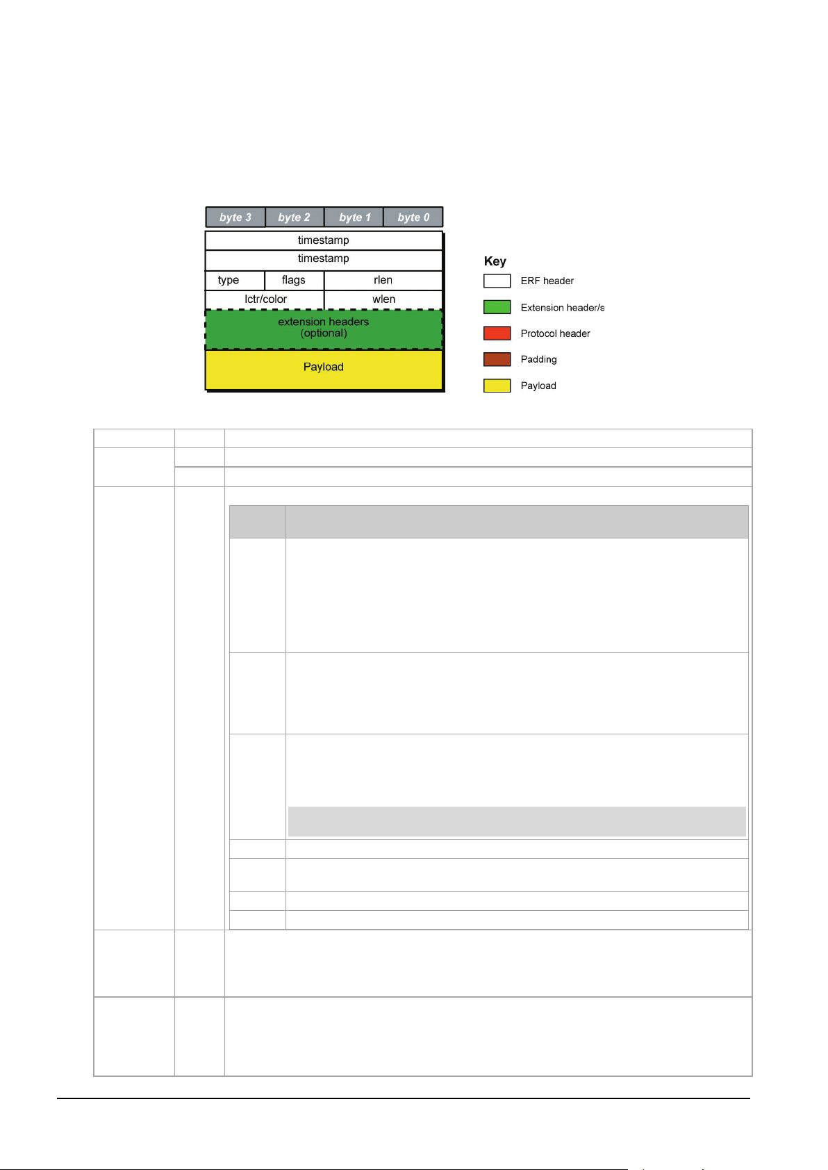
EDM01-36v10 DAG_9.2X2_Card_User_Guide - Data formats
timestamp
The time of arrival of the cell, an ERF 64-bit timestamp.
type
Bit 7
Extension header present.
Bit 6:0
ERF type. See table below:
flags
This byte is divided into several fields as follows:
1-0:
Binary enumeration of capture interface:
2:
Varying length record (vlen). When set, packets shorter than the snap length are
3:
Truncated record - insufficient buffer space.
Note:
4:
RX error. An error in the received data. Present on the wire
5:
DS error. An internal error generated inside the card annotator. Not present on
6:
Reserved
7:
Reserved
rlen Record length in bytes. Total length of the record transferred over the PCIe Gen 2.0 bus to
lctr / Colour
Depending upon the ERF type this 16 bit field is either a loss counter or color field. The
loss
Generic ERF header
All ERF records share some common fields. Timestamps are in little-endian (Pentium® native) byte order.
All other fields are in big-endian (network) byte order. All payload data is captured as a byte stream in
network order, no byte or re-ordering is applied.
The generic ERF header is shown below:
The fields are described below:
Bits Description
11 Interface 3 or D 10 Interface
2 or C
01 Interface 1 or B 00 Interface
0 or A
Cards with more than four interfaces typically use Multichannel ERF types (type 5
to 9, 12 and 17) which provide a separate larger interface field.
not padded and rlen resembles wlen.
When clear, longer packets are snapped off at snap length and shorter packets
are padded up to the snap length. rlen resembles snap length. Setting novarlen
and slen greater than 256 bytes is wasteful of bandwidth
• wlen is still correct for the packet on the wire.
• rlen is still correct for the resulting record. But, rlen is shorter than expected
from snap length or wlen values.
Truncation is depreciated and this bit is unlikely to be set in an ERF record.
the wire.
storage.
The timestamp of the next ERF record starts exactly rlen bytes after the start of the
timestamp of the current ERF record.
counter
records the number of packets lost between the DAG card and the stream buffer due
to overloading on the PCIe Gen 2.0 bus. The loss is recorded between the current record and
the previous record captured on the same stream/interface. The
66 ©2010 - 2012 Endace Technology Ltd. Confidential - Version 10 - May 2012
the appropriate ERF type details.
color field
is explained under
Page 73
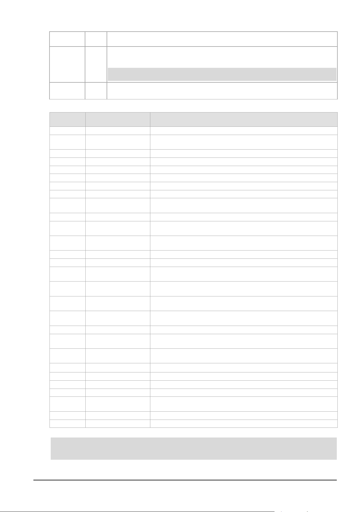
EDM01-36v10 DAG_9.2X2_Card_User_Guide - Data formats
wlen
Wire length. Packet length "on the wire" including some protocol overhead. The exact
extension
Extension headers in an ERF record allow extra data relating to each packet to be transported
Note:
Payload
Payload is the actual data in the record. It can be calculated by either :
ERF header types
0:
TYPE_LEGACY
Old style record
1:
TYPE_HDLC_POS
Packet over SONET / SDH frames, using either PPP or CISCO HDLC
2:
TYPE_ETH
Ethernet
3:
TYPE_ATM
ATM cell
4:
TYPE_AAL5
reassembled AAL5 frame
5:
TYPE_MC_HDLC
Multi-channel HDLC frame
6:
TYPE_MC_RAW
Multi-channel Raw time slot link data
7:
TYPE_MC_ATM
Multi-channel ATM Cell
8:
TYPE_MC_RAW_
Multi-channel Raw link data. Legacy ERF type - for DAG 3.7T and 7.1S
9:
TYPE_MC_AAL5
Multi-channel AAL5 frame
10:
TYPE_COLOR_HDLC_
HDLC format like TYPE_HDLC_POS, but with the LCNTR field reassigned as
11:
TYPE_COLOR_ETH
Ethernet format like TYPE_ETH, but with the LCNTR field reassigned as
12:
TYPE_MC_AAL2
Multi-channel AAL2 frame
13:
TYPE_IP_COUNTER
IP Counter ERF Record
14:
TYPE_TCP_FLOW_
TCP Flow Counter ERF Record
15:
TYPE_DSM_COLOR_
HDLC format like TYPE_HDLC_POS, but with the LCNTR field reassigned as
16:
TYPE_DSM_COLOR_
Ethernet format like TYPE_ETH, but with the LCNTR field reassigned as
17:
TYPE_COLOR_MC_
Multi-channel HDLC like TYPE_MC_HDLC, but with the LCNTR field
18:
TYPE_AAL2
Reassembled AAL2 Frame Record
19:
TYPE_COLOR_HASH_
Colored PoS HDLC record with Hash load balancing
20:
TYPE_COLOR_HASH_
Colored Ethernet variable length record with Hash load balancing
21:
TYPE_INFINIBAND
Infiniband Variable Length Record
22:
TYPE_IPV4
IPV4 Variable Length Record
23:
TYPE_IPV6
IPV6 Variable Length Record
24
TYPE_RAW_LINK
Raw link data, typically SONET or SDH Frame
25:
TYPE_INFINIBAND_
Infiniband link data.
32-47:
-
Reserved for Co Processor Development Kit (CDK) Users and Internal use
48:
TYPE_PAD
Pad Record type
Note:
interpretation of this quantity depends on physical medium. This may contain padding.
headers
to the host. Extension header/s are present if bit 7 of the type field is '1'. If bit 7 is '0', no
extension headers are present (ensures backwards compatibility).
There can be more than one Extension header attached to a ERF record.
• Payload = rlen - ERF header - Extension headers (optional) - Protocol header - Padding
Number Type Description
framing.
CHANNEL
POS
only.
COLOR
COUNTER
HDLC_POS
ETH
HDLC_POS
POS
ETH
LINK
COLOR
DSM COLOR
DSM COLOR
reassigned as COLOUR
The Ethernet frame begins immediately after the pad byte so that the layer 3 (IP) header is 32-bit
aligned.
©2010 - 2012 Endace Technology Ltd. Confidential - Version 10 - May 2012 67
Page 74
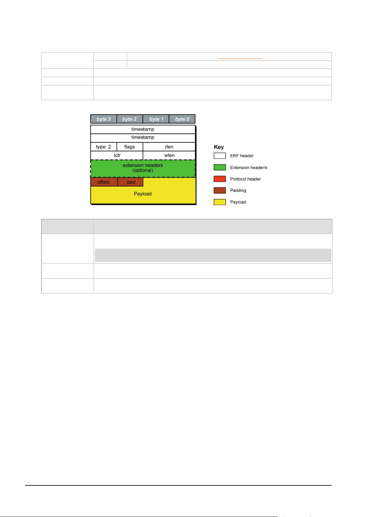
EDM01-36v10 DAG_9.2X2_Card_User_Guide - Data formats
Type
Bit 7
1 = Extension header present. See Extension Headers (page 69).
Bits 6:0
Type 2
Short description
TYPE_ETH
Long description
Type 2 Ethernet Record
Use
This record format is for Ethernet [802.3] data links. May be used with EH 12. Channelisation
Offset
Number of bytes not captured from start of frame. Typically used to skip link layer headers
Note:
Pad
The Ethernet frame begins immediately after the pad byte so that the layer 3 [IP] header is 32-
Payload
Payload = rlen - ERF header (16 bytes) - Extension headers (optional) - Padding (2 bytes)
ERF 2. TYPE_ETH
when created by software.
The TYPE_ETH record is shown below:
The following is a description of the TYPE_ETH record format:
Field Description
(1 byte)
when not required in order to save bandwidth and space.
This field is currently not implemented, contents should be disregarded.
(1 byte)
bit aligned.
(bytes of record)
68 ©2010 - 2012 Endace Technology Ltd. Confidential - Version 10 - May 2012
Page 75
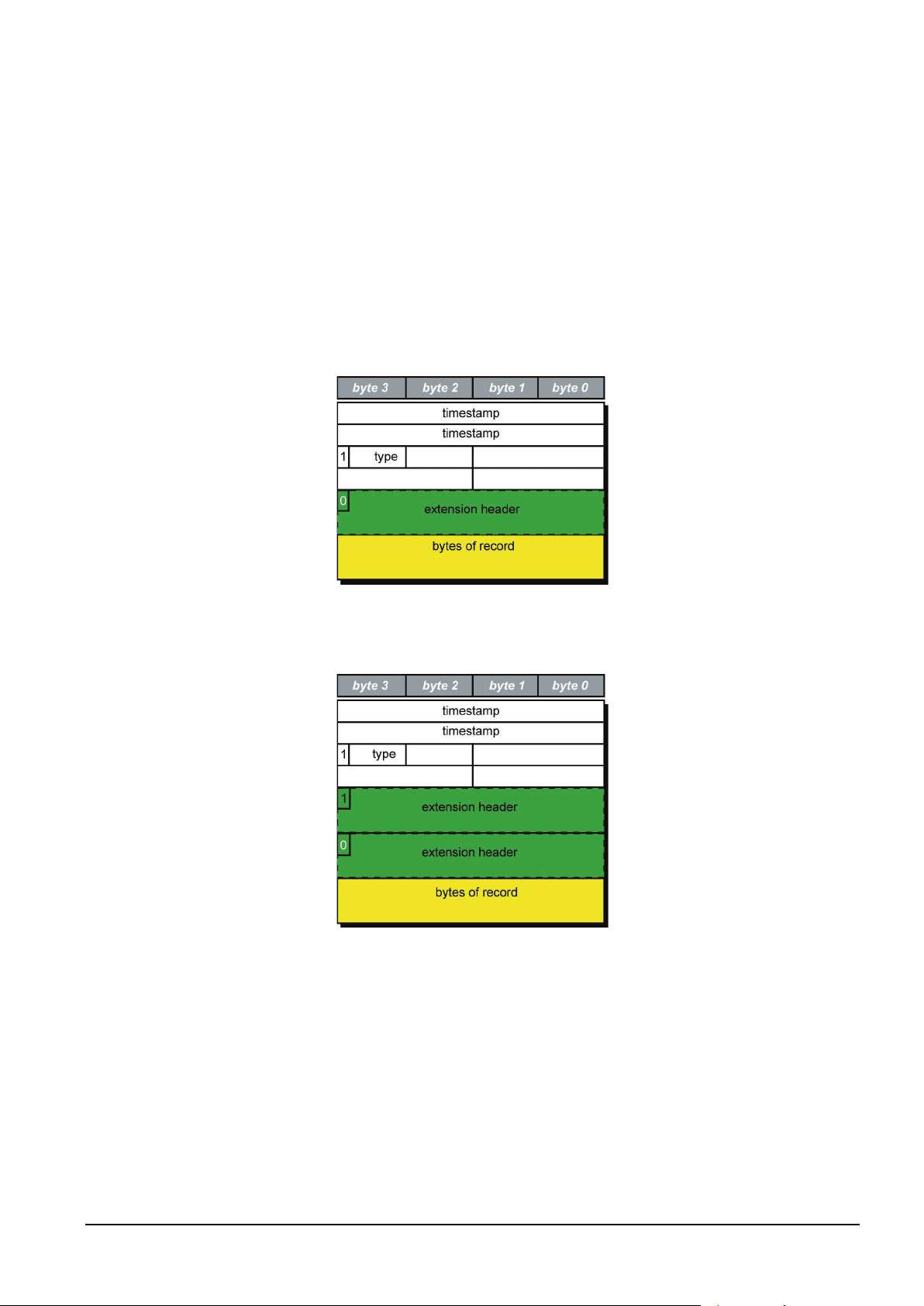
EDM01-36v10 DAG_9.2X2_Card_User_Guide - Data formats
Extension Headers (EH)
Introduction
The addition of an Extension Header into the ERF record allows extra data relating to the packet to be
transported to the host. The extension header allows certain features to be added independently of ERF
types, for example, features shared by different ERF records do not have to be implemented separately.
This results in automatic support across ERF types.
Bit 7 of the ERF type field is used to indicate that Extension Headers are present. If set to '1' Extension
Headers are present. The Extension Header type field indicates the type and format of the Extension
Header. It also indicates whether further Extension Headers are present. If bit 7 of the Extension Header
is set to '1' further Extension Headers exist in the record. The Extension Headers are 8 bytes in length.
The following diagram shows presence of an Extension Header in addition to the ERF record.
The following diagram shows presence of two Extension Headers with Bit 7 of the first Extension Header
set to '1'.
©2010 - 2012 Endace Technology Ltd. Confidential - Version 10 - May 2012 69
Page 76

Page 77
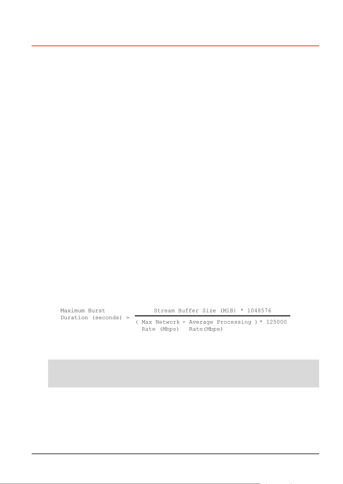
EDM01-36v10 DAG_9.2X2_Card_User_Guide - Guidance for stream buffer sizing
Note:
Guidance for stream buffer sizing
This section describes how to calculate the required stream buffer size for each DAG card on a particular
network. Once you have calculated the stream buffer requirements you need to ensure the memory
allocated to the DAG card is adequate, and update if required.
How the DAG card handles bursts of traffic depends on:
• the application processing rate - when the application processing rate slows, the stream buffer starts
to fill.
• the size of the stream buffer – how many packets can be held in the stream buffer before packet
loss occurs.
• the data arrival rate - Data rates above the application processing rate cause the stream buffer to fill.
Selecting stream buffer size
The DAG card writes the incoming traffic into the associated stream buffer. Applications, using DAG
APIs, read the data from the stream buffer.
Packet dropping occurs if the application cannot process the data fast enough and the stream buffer fills
up.
The required maximum size of the stream buffer is related to the following:
• Burst duration
• Latency
Burst duration
The incoming traffic does not arrive at a constant rate. It fluctuates between maximum and minimum
rates.
IF the incoming traffic rate exceeds the rate at which the application processes data, the buffer will start
to fill. In many cases the maximum burst rate will be equal to the link data rate (line rate). If there is
not enough room to accommodate the burst traffic, packets will be dropped.
The maximum burst duration can be defined as the maximum duration the stream buffer can receive
packets before dropping packets. It can be calculated as the time required to fill the stream buffer at
that maximum burst rate, with the application trying to empty the stream buffer at its processing speed.
To calculate the maximum burst duration, use the following formula:
Where the multipliers:
• 1048576 converts MiB to bytes.
• 125000 converts Megabits per second to bytes per second.
Applications writing data to disk can experience large delays when waiting for disk writes to complete. A
good rule of thumb is to size the stream buffer to accommodate a Maximum Burst Duration of at least
one second for such applications.
©2010 - 2012 Endace Technology Ltd. Confidential - Version 10 - May 2012 71
Page 78
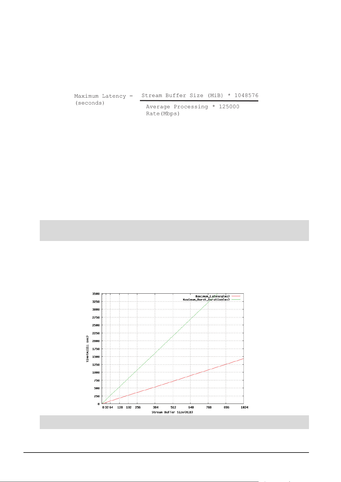
EDM01-36v10 DAG_9.2X2_Card_User_Guide - Guidance for stream buffer sizing
Note:
Note:
Latency
The latency is the time delay between:
• the packet being written to the stream buffer and
• the application reading the packet from the stream buffer.
The maximum latency is the time needed to empty an almost full stream buffer. To calculate the
maximum latency, use the following formula:
Where the multipliers:
• 1048576 converts MiB to bytes.
• 125000 converts Megabits per second to bytes per second.
Multiple streams
With multi-stream DAG cards, the incoming traffic can be spread across multiple streams for processing.
This allows you to take advantage of multi-core processors when processing large amounts of incoming
traffic.
This changes how you calculate the stream buffer size - you need to calculate the required stream buffer
size on a per stream basis. For example, in an 8 stream situation (assuming equal distribution of
incoming traffic over all streams) the effective incoming traffic rate to each stream is 1/8 of the original
rate. Use this value when calculating the values for the Network graph similar to the one above.
This works best when the incoming data is spread evenly across all streams. Where incoming traffic
cannot be spread evenly across stream you will need to adjust the stream buffer sizes for each stream.
Calculating the stream buffer size
Using the above two formulas you can calculate the Maximum Burst Duration and Maximum Latency for
any network and create a Network graph similar to the following. If plotted, you get a graph similar to
the following. See example 1 for the parameters for this graph.
We recommend that the stream buffers are a multiple of 4 MiB in size.
72 ©2010 - 2012 Endace Technology Ltd. Confidential - Version 10 - May 2012
Page 79
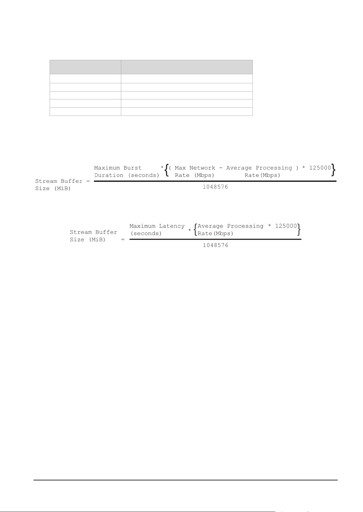
EDM01-36v10 DAG_9.2X2_Card_User_Guide - Guidance for stream buffer sizing
Network speed
10 Gigabits per second
Stream Buffer Size
To calculate
Max Network Rate
8 Gigabits per second per stream
Average Processing Rate
6 Gigabits per second per stream
Number of streams
1
Stream buffer burst duration
Stream buffer Latency
Example 1
Example network parameters:
Field Value
To calculate the stream buffer size range for a network with the above parameters, calculate the stream
buffer size using the maximum burst duration and the maximum latency formulas as shown below.
This formula calculates the minimum stream buffer size required to handle a particular burst duration.
This formula calculates the maximum stream buffer size guaranteeing a particular latency.
For traffic with one second maximum burst duration and 0.4 second maximum latency:
• Stream buffer based on burst duration = 244 MiB
• Stream buffer based on latency = 292 MiB
Therefore a stream buffer size between 244 and 292 MiB is required (in a multiple of 4 MiB).
©2010 - 2012 Endace Technology Ltd. Confidential - Version 10 - May 2012 73
Page 80

Page 81

EDM01-36v10 DAG_9.2X2_Card_User_Guide - Support
Existing support documentation
Updates
Further support
Support
This section describes how to access Endace Support for your Endace product.
To start, we recommend you visit the Endace Support website at https://support.endace.com/.
If you have a support contract with Endace you can login using your support username and password
which provides access to the secure area of the website. The website contains the latest versions of
software, user manuals, and release notes.
For more information about the Endace Support Package, or how to obtain (or change) your secure
support website login details, please contact [email protected].
Endace Support is available 24 hours, 7 days.
Many problems can be resolved by updating your software or firmware. Updates are also available on a
regular basis from the Endace Support website at https://support.endace.com/.
If your query is not answered by the existing documentation, or if the issue is not resolved by an update,
feel free to raise a Support Case via the Endace Support website https://support.endace.com/.
If you have a critical issue, please call. See Contact Details (page 77).
©2010 - 2012 Endace Technology Ltd. Confidential - Version 10 - May 2012 75
Page 82

EDM01-36v10 DAG_9.2X2_Card_User_Guide - Support
Note:
Requesting assistance
To request assistance from Endace support, complete one of the following:
• If you have successfully installed the DAG software on a Linux based system (except FreeBSD):
c. Run the Support Script (page 76
d. Attach the output file to an email containing the Required information (page 76) and a Severity
level (page 77).
e. Send the email to [email protected].
• If you have an alternative operating system or your DAG software has not been installed
successfully:
a. Fill out the Support Request Form (page 77
b. Submit the form.
Support script
To help gather important information on your system and DAG Card configuration, a tool is included in
your DAG software. This tool can only be used on Linux based systems (except FreeBSD) and collects the
following information:
• Installed DAG card(s)
• DAG card configuration(s)
• Operating system/kernel version
• Motherboard/RAM
To run this tool, use this command from the install location:
) to gather system and DAG Card setting information.
).
sh dag-stats.sh
This tool outputs a file called dag-test.log to the current directory.
Please check the contents of
dag-test.log
and remove any information which you feel is sensitive.
Required Information
The following information is always required by Endace Support when creating a Support Case:
1. Product description and serial number.
2. Your name.
3. Your email address.
4. Your phone number(s).
5. Your organization.
6. Your organization's full address, including physical and postal information, courier delivery
information, region and country.
7. Detailed description of the query / issue.
8. Detailed description of your product environment.
9. System dump or logfile.
10. Severity level.
76 ©2010 - 2012 Endace Technology Ltd. Confidential - Version 10 - May 2012
Page 83

EDM01-36v10 DAG_9.2X2_Card_User_Guide - Support
Note:
closing
Endace contact details:
Email:
USA (Toll Free):
+1 866 501 3356
UK (Toll Free):
+44 0800 051 3887
Australia (Toll Free):
+61 1800 144 708
New Zealand:
+64 7 959 2630
Support Website:
https://support.endace.com/
Severity Levels Described
A severity level is always required by Endace Support when submitting a Support Request. Please
remember to add a severity level to every Support Request. The following list describes each of the
severity levels.
Severity 1: Critical
Short Description: Service completely unavailable (production networks only).
Full Description: The Endace product is completely unavailable and there is no workaround. Service
needs to be restored immediately.
Severity 2: High
Short Description: Severely degraded service.
Full Description: The Endace product is severely degraded and there is no workaround, the product
performance is at unacceptable levels.
Severity 3: Medium
Short Description: Performance impaired.
Full Description: System performance is degraded, with a workaround in place. Operational performance
of the product is impaired but acceptable.
Severity 4: Low
Short Description: General assistance.
Full Description: The customer requires assistance on the use of the Endace product, but the issue does
not affect service.
This severity level is appropriate if the customer requires assistance on installation, configuration, feature
requests, general capability and product questions.
Endace Support will endeavor to resolve the problem as quickly as possible. If a workaround can be
achieved in a short time, it will be applied, and the priority of the case lowered while Endace Support
works on implementing a more permanent solution.
Reports subsequently made available about the case will reflect the priority of the case at the time of
, and not the priority of the case when it was raised.
Support request form
Endace has an on-line form that assists in gathering information for your support request.
The URL is: https://support.endace.com/RequestAssistance.aspx
Contact details
©2010 - 2012 Endace Technology Ltd. Confidential - Version 10 - May 2012 77
Page 84

Page 85
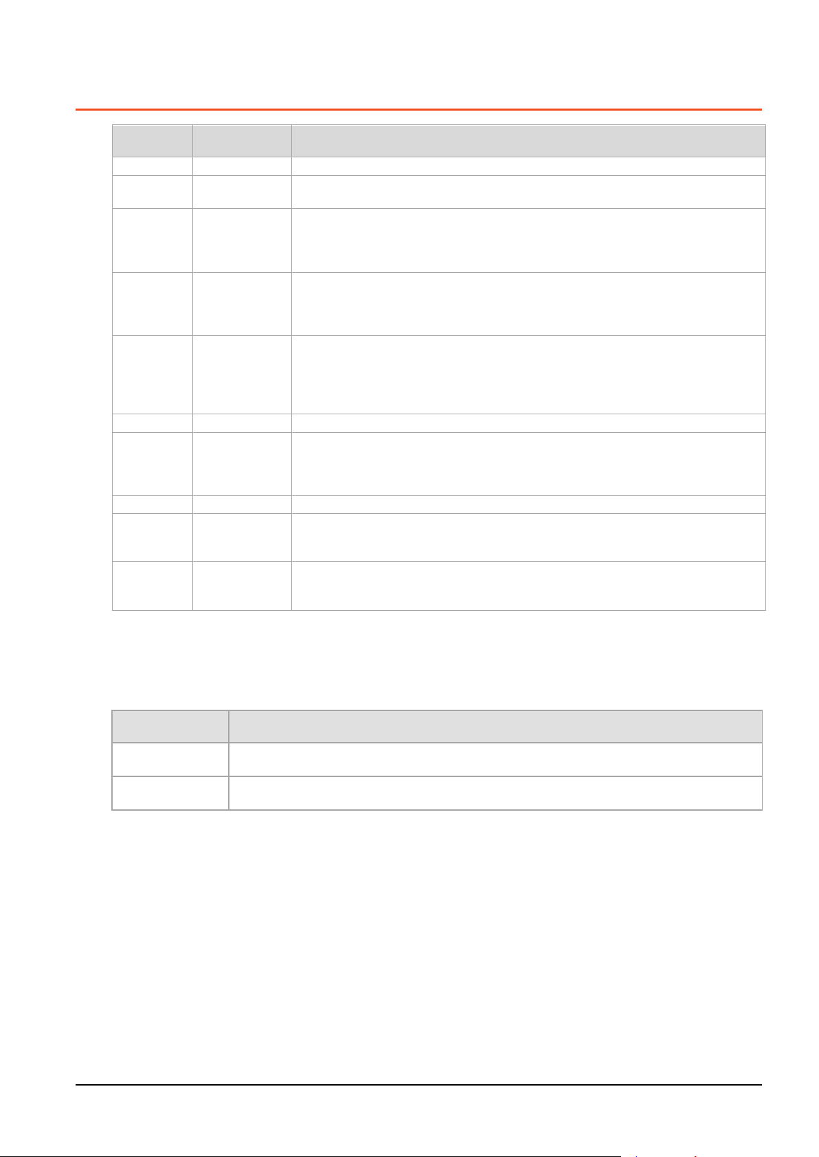
EDM01-36v10 DAG_9.2X2_Card_User_Guide - Version History
1
March 2010
First release. DAG 3.4.3 release.
2
March 2010
Removed IRIG-B - not in this release. Updated TDS info in time sync chapter.
3
July 2010
Preliminary release. Added new photo of slotted PCI bracket. Added BFS support
4
September 2010
4.0.1 release. Removed card architecture diagram. Added dagmem info. Changed
5
April 2011
DAG 4.2 release. Added 1G Ethernet and WAN support. Some restructuring of
6
November 2011
Updated interface status tables.
7
December 2011
DAG 4.7.0 - Windows support. Added reference to EDM04-37. Added details of the
8
February 2012
Corrected typo in the Warning - Thermal Trip section.
9
May 2012
DAG 4.7.1 - Updated Windows support information. Added dagconfig default
10
May 2012
DAG 4.2.2 release. Added TTR-TERF info, 10GBASE-ER line type, Pluggable copper
Preliminary
The products described in this technical document are in development and have yet to
Released
The products described in this technical document have completed development and final
Version History
Version Date Reason
Updated Dag card photo.
(TR TERF, EPP v2, IRIG-B). New firmware image. Updated dagconfig tokens,
Statistics Eth and WAN, universal counters. Added transmit information. Added new
dagconvert section. Readable DUCK 9.2X2 example. New support section.
image name. Added daginf sections. Updated Setting up the FPGA section. Updated
dagconfig output. Updated dagrom options. Updated dagconfig tokens list. Updated
dagconfig options. Updated Universal counters.
introductory sections. Updated Link Types, firmware images, transceiver types,
dagconfig outputs, dagconfig token list, dagconfig interface status printouts.
Updated TR-TERF CRC stripping topics. Updated DUCK output. Corrected Dagclock
output tables.
new Windows Server tools DAG Device and WinDAG Command Prompt. Added
details on allocating memory and updating drivers for Windows. Updated details for
the following DAG tools: dagconfig, dagsnap, dagbits, dagconvert, dagclock.
information. Updated Optical modules information. Updated Optical Modules.
Updated copper transceiver information.
transceivers change to 1000 only, dagdetect options. Updated dagrom options,
dagconfig tokens list, dagconfig options, transmit description, dagclock options,
b
Status Description
complete final production quality assurance.
production quality assurance.
©2010 - 2012 Endace Technology Ltd. Confidential - Version 10 - May 2012 79
Page 86

 Loading...