

Enda EPV242-R-230VAC-RS, EPV242-230VAC-RS, EPV242-R-110VAC-RS, EPV242-110VAC-RS, EPV242-R-24VAC-RS User manual [ml]
...Page 1

Read this document carefully before using this device. The guarantee will be expired by damaging of the device if you don't
attend to the directions in the user manual. Also we don't accept any compensations for personal injury, material damage or
capital disadvantages.
ENDA EPA242 PROGRAMMABLE AC/DC AMMETER
Thank you for choosing rogrammable AC/DC mmeterENDA EPA242 P A
77 x 35mm sized
4 digits display
Easy to use with front panel keypad
5A or 60mV, CT20/30 Current Transformer or 60mV input (Specify at Order)
Programmable scale between 5A and 9999A
Multifunctional alarm output (NO+NC) for upper and lower limits
Communication feature over isolated RS485, using ModBus RTU protocol ( )
Measuring type can be selected as AC, DC or true RMS
Key lock feature
0-20mA, 4-20mA, 0-10V or 1-5V Output selection (For only “A” type output devices)
CE marked according to European Norms
CT20/30 Current Transformer must be ordered separately.
Order Code : EPA242 - - - -
1 3 4
2
1 - Input
CT.......CT20/30 Current
Transformer Input or 60mV
Blank....5A or 60mV
2 - Output
R..........Relay
A...........Analog Output
Blank....No Output
(Optional)
Optional
3 - Supply Voltage
230VAC...230V AC
110VAC...110V AC
24VAC.....24V AC
SM...........9-30V DC / 7-24V AC
OUT AC DC ACDC
0.000
ENDA
4 Isolated ModBus -
RS ...... ModBus
I Isolated
Specify at Order .
( )
english
A
SET
EPA242
TECHNICAL SPECIFICATIONS
ENVIRONMENTAL CONDITIONS
Ambient/stroge temperature
Max. Relative humidity
Rated pollution degree
Height
Do not use the device in locations subject to corrosive and flammable gases.
ELECTRICAL CHARACTERISTICS
Supply
Power consumption
Wiring
Scale
Sensitivity
Accuracy
Input Range
Input Impedance
Frequency Range
EMC
Safety equirementsR
or CT20/30 input devices 0....150mA-5A...5A
-60mV...60mV
OUTPUTS
outputAnalog
Alarm output
Life expectancy for relay
HOUSING
Housing type
Dimensions
Weight
Enclosure material
0 ... +50°C/-25 ... 70°C
80 up to 31Relative humidity for temperatures% °C decreasing linearly 50% at 40°C., to
According to EN 60529 Front panel : IP6 , Rear5 panel : IP20
Max. 2000m
230V AC +10% -20%, 50/60Hz or 24V AC 10% , 50/60Hz or optional 9-30V DC / 7-24V AC 10% SMPS± ±
Max. VA5
2.5mm² screw-terminal connections
AC and RMS
DC
0.002A x ( e.g ; For , sensitivity is )c.tr.r 5 = 0.01Ac.tr.r
AC
DC
RMS
10
and
9
and
10
and
1
9
and
40k
DC , 10Hz - 200Hz ( For square wave form)10Hz - 70Hz
EN 61326-1: 2013
EN 61010-1: 20 (Pollution degree 2, overvoltage category II)10
0-20mA DC, 4-20mA DC, 0-10V DC 1-5V DC . ( Ω)or selection Load resistance for current outputs are max. 500
Relay: 250V AC, 8A (for resistive load), NO+NC
Mechanical 30.000.000 ; Electrical 100.000 operation.
Suitable for flush-panel mounting. (According to DIN 43 700)
W7 xH xD mm7 35 61
Approx. 50g (after packing)2
Self extinguishing plastics.
While input type in 5A / 60mv ; = 0A...5A 0A...9999A ( Determined by parameter. e.g ; If , scale is )c.tr.r c.tr.r 5
While input type in CT20/30 / 60mV ;
= 0A...300A = 0A...300A
If , input range is ( Determined by parameter. e.g ; If , scale is )
ityp Ct20 turn turn 1
= 0A...120A = 0A...120A
If , input range is ( Determined by parameter. e.g ; If , scale is )
ityp Ct30 turn turn 1
= 0A..9999A = 0A...5A
If , input range is (Determined by parameter. e.g ; If , scale is )
ityp 5Hnt c.tr.r c.tr.r 5
While input type in 5A / 60mv ; = -5A...5A -999A...9999A ( Determined by parameter. e.g ; If , scale is )c.tr.r c.tr.r 5
While input type in CT20/30 / 60mV ;
DC Measurement can not be performed by using current transformer.
= 0A..9999A = -5A...5A
If , input range is (Determined by parameter. e.g ; If , scale is )ityp 5Hnt c.tr.r c.tr.r 5
±
±
±
11
12
11
12
%1
%1
%1
2mΩ
Ω
(full scale) ( For square wave form)± 2%
(full scale)
(full scale) ( For square wave form)± 2%
( Device 10A current )
( Device 50V voltage )
may be damaged at and above s
may be damaged at and above s
While cleaning the device, solvents (thinner, , acid etc.) or corrosive materials must not be used.gasoline
SURAN Industrieelektronik
Dettinger Str. 9 / D-72160 Horb a.N
Tel.: +49 (0)7451 / 625 617
Fax: +49 (0)7451 / 625 0650
E-mail : info@suran-elektronik.de
Internet : www.suran-elektronik.de
EPA242-E-290319
1. / 4
Page 2
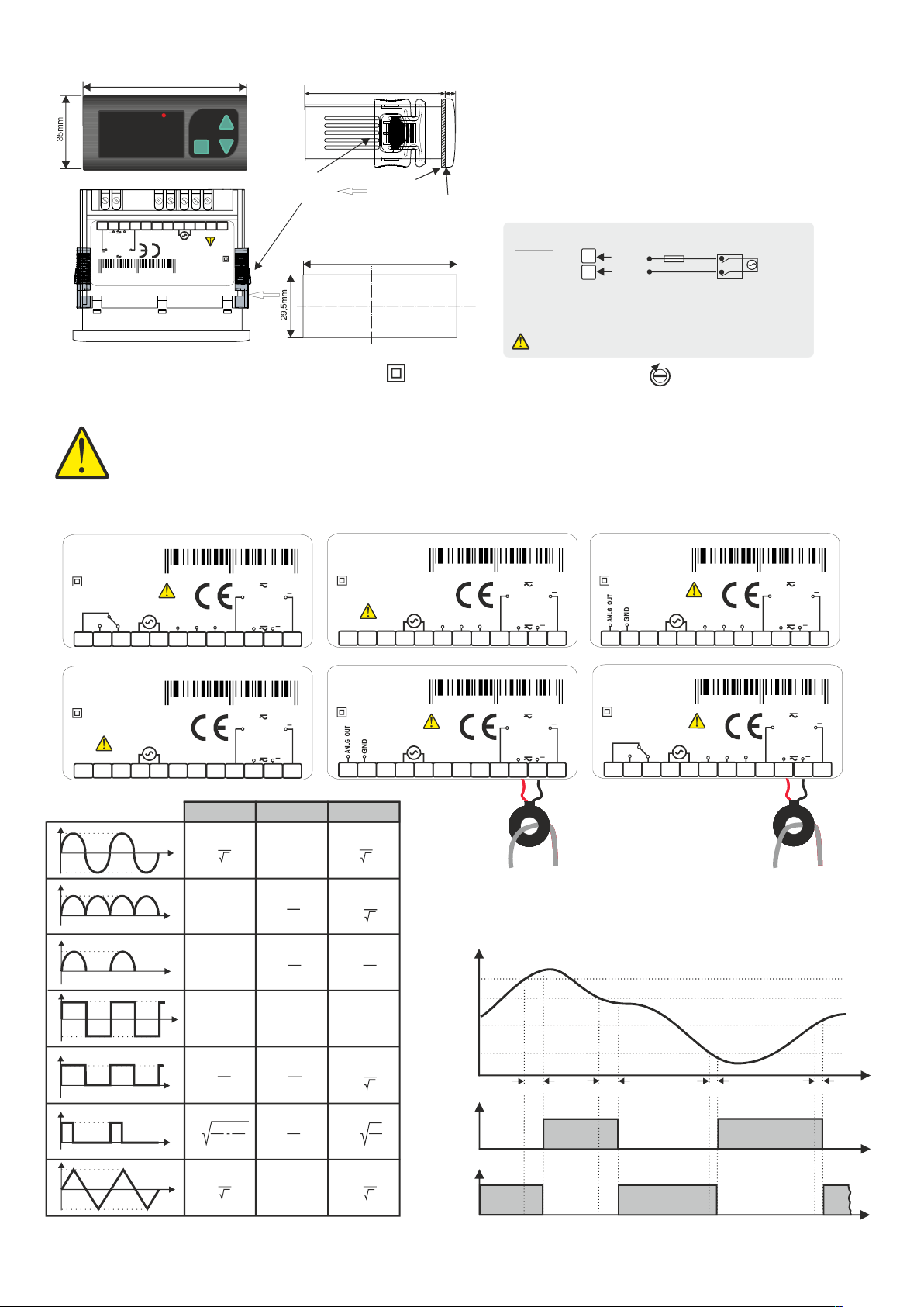
DIMENSIONS
8680407704309
8 68 04 07 704309
8 68 04 07 704316
8 68 04 07 704323
8 68 04 07 704330
8 68 04 07 704323
8 68 04 07 704330
77mm
OUT AC DC ACDC
A
0.000
ENDA
12
10
11
+
AC / DC
5AMax.
AC / DC
+
Max.
60mV
SN: XXXXXXXXX
SETSET
EPA242
7 8 9
1 2 3 4 5 6
50/60Hz 5VA
230V AC +10% -20%
CAT II
Made in Turkey
CONNECTION DIAGRAM
ENDAEPA242 is intended for installation in control panels. Make sure that the device is used only for intended purpose.The electrical
connections must be carried on by a qualified staff and must be according to the relevant locally applicable regulations. During an
installation, all of the cables that are connected to the device must be free of electrical power. The device must be protected against
inadmissible humidity, vibrations and severe soiling. Make sure that the operation temperature isnot exceeded. The cables should not
be close to the power cables or components.
CAUTION :
If 5A / CT20-30 and 60mV inputs are connected at the same time, the measurement will be incorrect.
AC/DC AMMETER
PROGRAMMABLE
EPA242-230VAC
ENDAIND USTRIAL ELECTRONICS
1
Flush mounting
clamp
Depth
61mm
2
Panel
Panel cut-out
71,5mm
For removing mounting clamps :
Push the flush-mounting
5mm
-
clamp in direction as
shown in the figure left.
Then, pull out the clamp in
-
direction
2.
:Note
1)2)Panel thickness should be maximum mm.
There must be at least 60
behind the device otherwise
Rubber packing
to remove it from the panel.
NOTE :
SUPPLY:
184-253V AC
50/60Hz 7VA
1) Mains supply cords shall meet the requirements of IEC 60227
or IEC 60245.
2) In accordance with the safety regulations, the power supply
switch shall bring the identification of the relevant instrument
and it should be easily accessible by the operator.
Fuse should be connected.
Equipment is protected throughout by DOUBLE
INSULATION
4
5
1
, it would be difficult
mm free space
F 100mA
250V AC
Line
Neutral
7
Fuse
Switch
Cable size: 1,5mm²
Holding screw 0.4-0.5Nm.
230V AC
Supply
ENDAINDUSTRIAL ELECTRONICS
EPA242-R-230VAC-RSI
PROGRAMMABLE
AC/DC AMMETER
Made in Turkey
CAT II
OUTPUT
250V AC 8A
RESISTIVE LOAD
230V AC +10% -20%
50/60Hz 5VA
COM.
B
1 2 3 4 5 6
ENDAINDUSTRIAL ELECTRONICS
EPA242-230VAC
PROGRAMMABLE
AC/DC AMMETER
Made in Turkey
CAT II
230V AC +10% -20%
50/60Hz 5VA
1 2 3 4 5 6
A
0
-A
A
0
A
0
A
0
-A
A
0
T
T/2
T
T/2
T/2
T
T
T/2
T
T/2
3T/2
3T/2
3T/2
3T/2
3T/2
2T
2T
2T
2T
A
7 8 9
7 8 9
ac
1
A
2
0.308 A
0.386 A
A
1
A
2
SN: XXXXXXXXX
Max.
+
AC / DC
Max. 5A
AC / DC
+
10
SN: XXXXXXXXX
Max.
+
AC / DC
Max.
AC / DC
+
10
60mV
11
60mV
5A
11
12
12
dc
0.000
2
A
π
1
A
π
0.000
1
A
ENDAINDUSTRIAL ELECTRONICS
EPA242-230VAC-RSI
PROGRAMMABLE
AC/DC AMMETER
Made in Turkey
CAT II
230V AC +10% -20%
50/60Hz 5VA
1 2 3 4 5 6
ENDAINDUSTRIAL ELECTRONICS
EPA242-CT-A-230VAC
PROGRAMMABLE
AC/DC AMMETER
Made in Turkey
CAT II
230V AC +10% -20%
50/60Hz 5VA
1 2 3 4 5 6
(rms)
Ac.dc
1
A
2
1
A
2
1
A
2
A
1
2
A
2
B
COM.
A
7 8 9
7 8 9
CT20
SN: XXXXXXXXX
Max.
+
AC / DC
Max. 5A
AC / DC
+
10
SN: XXXXXXXXX
Max.
+
AC / DC
CT20/30
AC / DC
+
10
Ct20
Ct20
60mV
60mV
TC 20TC 20
TC 20
11
12
11
12
ENDAINDUSTRIAL ELECTRONICS
EPA242-A-230VAC-RSI
PROGRAMMABLE
AC/DC AMMETER
Made in Turkey
CAT II
230V AC +10% -20%
50/60Hz 5VA
1 2 3 4 5 6
ENDAINDUSTRIAL ELECTRONICS
EPA242-CT-R-230VAC-RSI
PROGRAMMABLE
AC/DC AMMETER
Made in Turkey
CAT II
OUTPUT
250V AC 8A
RESISTIVE LOAD
230V AC +10% -20%
50/60Hz 5VA
1 2 3 4 5 6
B
B
COM.
COM.
B
A
7 8 9
A
7 8 9
CT30
Max.
+
AC / DC
+
+
Measurement input 0-300A Measurement input 0-120A
OUTPUT CHART
dly.U
UP.l1 HYS.U +
LO.l1 HYS.L +
Input
UP.l1
LO.l1
OUT1
dly.U
SN: XXXXXXXXX
60mV
Max. 5A
AC / DC
11
10
SN: XXXXXXXXX
Max.
60mV
AC / DC
CT20/30
AC / DC
+
11
10
TC 20TC 20
TC 30
Ct20
Ct20
dly.ldly.l
12
12
t
A
d
0
A
0
-A
SURAN Industrieelektronik
SURAN Industrieelektronik
Dettinger Str. 9 / D-72160 Horb a.N
Dettinger Str. 9 / D-72160 Horb a.N
d
T
T
3T/2
T/2
A
2T
2
T
T
2
d
d
d
A
T
d
A
T
A.out n.o. =
t
OUT1
1
2T
A
3
0.000
1
A
3
A.out n.c. =
t
Tel.: +49 (0)7451 / 625 617
Tel.: +49 (0)7451 / 625 617
Fax: +49 (0)7451 / 625 0650
Fax: +49 (0)7451 / 625 0650
E-mail : info@suran-elektronik.de
E-mail : info@suran-elektronik.de
Internet : www.suran-elektronik.de
Internet : www.suran-elektronik.de
EPA242-E-290319
2. / 4
Page 3

OUT AC DC ACDC
A
0.000
ENDA
If these keys are pressed and held for 3 seconds, “Programming Mode” is entered or it returns to “Running Mode”. If and keys are pressed
&
while parameter names are displayed, than it returns to measured value.
SETSET
EPA242
PROGRAMMING DIAGRAM
Increment
key
Decrement
key
Programming
key
SET
Used for increasing the setpoint value and changing parameters.
When held down for a few seconds, configured numeric value increases faster.
Used for decreasing the setpoint value and changing parameters.
When held down for a few seconds, configured numeric value increases faster.
Used for displaying and configuring the selected parameter value.
PROGRAMMING MODE
SET
ConF
& &
Current Conversion Ratio
tYpE
d.pnt
Opnt
Adr5
It can be adjusted between and (/5). If this parameter
changes, upper limit value is set to maximum scale ,minimum limit value is
set to minimum scale and hysteresis values are set to .
Measuring Method
It can be adjusted , ortoac dc acdc.LEDs on the top of the display
indicates the adjusted measurement method.
Decimal Indicator
If measured value is lower than 10, it can be shown
0
( ) , ( ) , ( ) or ( ).
0.0 0 0.00 0.0 0
measured value between 10 and 100 it can be shown as
If ,
( ) ,( ) or ( ).
0.00 0.0 0
If measured value between 100 and 1000, it can be shown as
( ) or ( ) .
0.0 0
Decimal point moves automatically according to displayed value on
the screen.
Samping Time
If 1 ( ) is selected ; sampling time of the measurement is 250ms,
1
If 2 ( ) is selected, it is 500ms. If 3 ( ) is selected, it is 750ms.
2 3
If 4 ( ) is selected, it is 1 second.
4
Device Address
It can be adjusted between - .1 247
5.00(/5)
9999
0.1
as
Out1
OtYp
UPLL
HYSU
dLYU
LOLL
i
Includes in R extension devices.
Out1 Output
It can be adjusted as or If is selected, incase of
alarm, out relay is activated.
Upper Limit Value
It can be adjusted between minimum and maximum scale that is
specified with parameter. This parameter can’t be lower than
( )
l0ll - HY5U - HY5L
Hysteresis Value for Upper Limit
It can be adjusted between and parameter. This
parameter can’t be higher than ( ).
When changed, gets the value of .
ctrr HY5U 0.1
Delay Time for Upper Limit Alarm
It can be adjusted between and .0 900
Lower Limit Value
It can be adjusted between lower scale and upper scale that is specified with
parameter.
c.tr.r
This parameter can’t be higher than ( ) value.
n.o. N.c. n.o
c.tr.r
SET
0 ctrr /5
- - HY5L
Upll l0ll
UPLL - HY5U - HY5L
B Rateaud
bAUd
ityP
turn
AtyP
It can be adjusted as , , , , , ,
38400 57600 115200 .
Input Type ( In devices with input type "CT" )
Can be adjusted to , and values.Ct20 CT30 5HNt
5HntIf is selected, 60mV input terminal must be used.
Number of Windings ( In devices with input type "CT" )
Number of windings of the current cable getting through the CT20/30
current transformer.
Please see "CT20/30 Current Transformer & Windings" chart on
the right of this page.
Analog Output Status ( In devices with output type "Analog" )
Can be adjusted to , , and values.0 - 20 4 -20 0 -10 1 - 5
OFF 1200 2400 4800 9600 19200
, and
LOCKING & UNLOCKING KEYPAD
Measured Value
L0C
In “Running Mode” , by pressing to key for 3 seconds, keypad locked or unlocked.
0.00
UL0C
Measured Value
0.00
0.00
QUICK MENU
SET
By pressing to key for 3 seconds, quick menu is entered.
UPLL
SET
LOLL
Measured Value
+
0.00
REVISION NUMBER
SET
&
&
SET
&
&
While revision information displayed and if one of the pressed key
is released, measured value is displayed again.
Day.Month
01.01
If these keys are pressed and held together, revision
date appears as day, month and year.
Year
2015
Measured Value
0.00
ERROR MESSAGES
Measured current value is
higher than maximum scale.
Measured current value is
lower than minimum scale.
HYSL
dLyL
5dly
It can be adjusted between and . This parameter can’t be
higher than ( ) value. When is
changed, gets the value of .
Delay Time for Lower Limit Alarm
It can be adjusted between and seconds.0 900
Delay Time for Initial Upper Limit Alarm
It can be adjusted between and seconds.0 900
- - ctrr
UPLL L0LL HY5U
HY5U 0.1
0 Ctrr /5
Hysteresis Value for Lower Limit
DEFAULT SETTINGS
Powered on device by pressing key. message appears
dPAr
on display and device reset to default settings.
CT20/30 Current Transformer & Windings Chart
C 20T
CT30
turn
I max(A)in
I max(A)in
1 2 3 4 5
300
150 100
120
60 40 30 24 20
75
60
50
6
7 8
42,8
17,1
37,5
15
9 10
33,3 30
12
13,3
Note :
If = , parameter is not appears.
ityp 5hnt turn
If = or , parameter is not appears.
ityp Ct20 Ct30 ctrr
Note :
Before setting the relay parameters, the operating scale must be
determined from parameter.
If , and parameters are changed, ,
dpnt typE Ityp Upll
, and values must be checked.
loll Hy5U Hy5l
SET
tYPE
SET
If key is pressed, the current value of the parameter appears by flashing on the display.
By using “UP” or “DOWN” navigation keys, selected parameter can be adjusted to
the desired value.
SET
After the setting up the parameters, if set key is pressed again, adjusted parameter
name appears on display.
dpnt
SETTING UP THE PARAMETERS
dC
ACdC
SET
SURAN Industrieelektronik
SURAN Industrieelektronik
Dettinger Str. 9 / D-72160 Horb a.N
Dettinger Str. 9 / D-72160 Horb a.N
Tel.: +49 (0)7451 / 625 617
Tel.: +49 (0)7451 / 625 617
Fax: +49 (0)7451 / 625 0650
Fax: +49 (0)7451 / 625 0650
E-mail : info@suran-elektronik.de
E-mail : info@suran-elektronik.de
Internet : www.suran-elektronik.de
Internet : www.suran-elektronik.de
EPA242-E-290319
3. / 4
Page 4

ENDA EPA242 DIGITAL AMPERMETER MODBUS PROTOCOL ADDRESS MAP
HOLDING REGISTERS FOR R EXTENSION DEVICES
Holding Register
Addresses
Decimal
0000d
0001d
0002d
0003d
0004d
0005d
0006d
0007d
0008d
0009d
0010d
0011d
0012d
0013d
* 0014d
* 0015d
* 14 and 15 Addresses are used only in devices with input type CT20/30.
0x0000
0x0001
0x0002
0x0003
0x0004
0x0005
0x0006
0x0007
0x0008
0x0009
0x000A
0x000B
0x000C
0x000D
0x000E
0x000F
Hex
Data
Type
word
OUT1 output status
word
Current conversion ratio
word
The upper limit of the setpoint
word
The upper limit of the hysteresis value
word
Delay time for the upper limit alarm
The lower limit of the setpoint
word
word
The lower limit of the hysteresis value
Delay time for the lower limit alarm
word
word
Measurement method ( =0 AC 1 DC 2 ACDC, = , = )
Decimal point. (0 = , 1 = , 2 = , 3 = )0 0.0 0.00 0.000
word
Sampling time of the measurement value. If 1 is selected, it is
word
250ms. If 2 is selected, it is 500ms. If 3 is selected, it is 750ms.
If 4 is selected, it is 1 second.
Device address for RS485 network connection.
word
Adjustable between 1-247.
Baudrate (0=Off;1=1200;2=2400; 3=4800; 4=9600; 5=19200
word
6= 38400; 7= 57600; 8= 115200)
word
Delay Time for Initial Upper Limit Alarm
Input type ( , ,0=Ct20 1=Ct30 2 5Hnt= )
word
word
Number of windings for transformer
Data Content
Parameter
Name
0tyP
ctrr
UPLL
HY5U
dlyU
L0Ll
HY5L
dLyl
typE
dpnt
OPTN
aDr5
BAUD
5dly
ityp
turn
Holding Register Parameter Table (For devices with “No Relay” and “A” type output models)
0000d
0001d
0002d
0003d
0004d
0005d
* 0006d
* 0007d
** 0008d
* 6 and 7 Addresses are used only in devices with input type CT20/30.
** 8 Address is used only in devices with output type “A”.
In devices with input type CT20/30, following parameter settings will change automatically if the parameter is changed.ityp
If = ; = , = , = , =
If = ; = , = , = , =
0x0000
0x0001
0x0002
0x0003
0x0004
0x0005
0x0006
0x0007
0x0008
ityp Ct20 UpLL 300.0 LoLL 0 Hy5U 0.10 Hy5L 0.10
ityp Ct30 UpLL 120.0 LoLL 0 Hy5U 0.10 Hy5L 0.10
Current conversion ratio
word
Measurement method ( =0 AC 1 DC 2 ACDC, = , = )
word
Decimal point. (0 = , 1 = , 2 = , 3 = )0 0.0 0.00 0.000
word
Sampling time of the measurement value
word
Device address for RS485 network connection.
word
Adjustable between 1-247.
Baudrate (0=Off;1=1200;2=2400; 3=4800; 4=9600; 5=19200
word
6= 38400; 7= 57600; 8= 115200)
Input type ( , ,0=Ct20 1=Ct30 2 5Hnt= )
word
word
Number of windings for transformer
Analog output type (0= , 1= , 2= ,3= )0-20 4-20 0-10 1-5
word
ctrr
typE
dpnt
0PTN
aDr5
BAUD
ityp
turn
Atyp
Read/Write
Permission
Read / Write
Read / Write
Read / Write
Read / Write
Read / Write
Read / Write
Read / Write
Read / Write
Read / Write
Read / Write
Read / Write
Read / Write
Read / Write
Read / Write
Read / Write
Read / Write
Read / Write
Read / Write
Read / Write
Read / Write
Read / Write
Read / Write
Read / Write
Read / Write
Read / Write
INPUT REGISTERS FOR R EXTENSION DEVICES
Input Register
Addresses
Decimal
0000d
0001d
0x0000
0x0001
Hex
Data
Type
word
Measured current value
word
Decimal point of measured current value
Data Content
Parameter
Name
--
--
Read/Write Permission
Read Only
Read Only
DISCRETE INPUTS FOR R EXTENSION DEVICES
Discrete Input
Addresses
Decimal
00d
Hex
0x00
Data
Type
Bit
Relay output state (0= ; 1= )OFF ON
Data Content
Parameter
Name
--
Read/Write Permission
Read Only
COILS FOR R EXTENSION DEVICES
Status
Value
no
5
5.00
0.10
0
0.00
0.10
0
aCdC
0.00
4
1
oFF
0
ct20
1
5
aCdC
0.00
4
1
9600
ct20
1
0 - 20
Coil Addresses
Decimal
00d
Hex
0x00
Note 1 : Coil and Discrete input parameters are not available in the devices those have no relay
Note 2 : menu parameters can be used as “Holding Register” or “Coil.0tyP
Note 3 : Value read in 0th address of input register gives the measured value. Also, the 1st address of the input register
specifies the decimal part of the measured current value.
For example ;
Value read in 0th address of input register is 2842, if value read in 1st address from input register as 1, it is 284.2
Value read in 0th address of input register is 2842, if value read in 1st address from input register as 2, it is 28.42
Value read in 0th address of input register is 2842, if value read in 1st address from input register as 3, it is 2.842
SURAN Industrieelektronik
SURAN Industrieelektronik
Dettinger Str. 9 / D-72160 Horb a.N
Dettinger Str. 9 / D-72160 Horb a.N
Data
Type
Bit
Output state (0= ; 1= )no nc
Tel.: +49 (0)7451 / 625 617
Tel.: +49 (0)7451 / 625 617
Fax: +49 (0)7451 / 625 0650
Fax: +49 (0)7451 / 625 0650
Data Content
E-mail : info@suran-elektronik.de
E-mail : info@suran-elektronik.de
Internet : www.suran-elektronik.de
Internet : www.suran-elektronik.de
Parameter
Name
0typ
Read/Write
Permission
Read / Write
Status
Value
4. / 4
EPA242-E-290319
 Loading...