

Page 1

Orbit V2
OPERATION MANUAL
E-mu Systems, Inc.
Page 2

Operation Manual
© 1996 E-mu Systems, Inc.
All Rights Reserved
• FI560 Rev. A
E-mu World Headquarters
E-mu Systems, Inc. U.S.A.
P.O. Box 660015
Scotts Valley, CA USA
95067–0015
Telephone: 408-438-1921
Fax: 408-438-8612
Important Notice:
In order to obtain warranty service on your Orbit unit, the serial number sticker
must be intact and you must have a sales receipt or other proof of purchase. If there
is no serial number sticker on your Orbit, please contact E-mu Systems at once.
This product is covered under one or more of the following U.S. patents:
4,404,529; 4,506,579; 4,699,038; 4,987,600; 5,013,105; 5,072,645;
5,111,727; 5,144,676; 5,170,367; 5,248,845; 5,303,309; 5,317,104; 5,342,990;
5,430,244 and foreign patents and/or pending patents. Orbit is a registered
trademark of E-mu Systems, Inc.
Europe, Africa, Middle East
E-mu Systems, Ltd.
Suite 6, Adam Ferguson House
Eskmills Industrial Park
Musselburgh, East Lothian
Scotland, EH21 7PQ
Telephone: +44 (0) 131-653-6556
Fax: +44 (0) 131-665-0473
PRINTED AND MADE IN THE USA
Page 3
WARNING: READ THIS FIRST!
IMPORTANT SAFETY INSTRUCTIONS
Use in countries other than the U.S.A. may require the use of a different line
cord or attachment plug, or both. To reduce the risk of fire or electric shock,
refer servicing to qualified service personnel. To reduce risk of fire or electric
shock do not expose this product to rain or moisture.
GROUNDING INSTRUCTIONS
This product must be grounded. If it should malfunction or break down,
grounding provides a path of least resistance for electric current, reducing the
risk of electric shock. This product is equipped with a cord having an
equipment-grounding conductor and a grounding plug. The plug must be
plugged into an appropriate outlet properly installed and grounded in
accordance with all local codes and ordinances.
DANGER
Improper connection of equipment grounding conductor can result in the
risk of electric shock. Check with a qualified electrician or service personnel
if you are in doubt as to whether the product is properly grounded. Do not
modify the plug provided with this product — if it will not fit the outlet,
have a proper outlet installed by a qualified technician.
CAUTION
If the 9090, Orbit V2 is rack mounted, a standard 19-inch open frame rack
must be used.
USER-MAINTENANCE INSTRUCTIONS
1. Orbit should be kept clean and dust free. Periodically wipe the unit with a
clean, lint free cloth. Do not use solvents or cleaners.
2. There are no user lubrication or adjustment requirements.
3. Refer all other servicing to qualified service personnel.
INSTRUCTIONS PERTAINING TO A RISK OF FIRE,
ELECTRIC SHOCK, OR INJURY TO PERSONS
WARNING; When using electric products, basic precautions should
always be followed, including the following:
1. Read all instructions before using Orbit.
2. To reduce the risk of injury, close supervision is necessary when Orbit is
used near children.
3. Do not use Orbit near water — for example near a bathtub, washbowl,
kitchen sink, in a wet basement, on a wet bar, or near or in a swimming
pool.
This symbol is intended to alert
the user to the presence of
important operating and
maintenance (servicing)
instructions in the literature
accompanying the appliance.
This symbol is intended to alert
the user to the presence of
uninsulated dangerous voltage
within the product's enclosure
that may be of sufficient
magnitude to constitute a risk of
electric shock to persons.
Page 4

SAVE THESE INSTRUCTIONS
4. Orbit should be situated so that its location or position does not interfere
with its proper ventilation.
5. Orbit should be located away from heat sources such as radiators, heat
registers, fireplaces, stoves, or ovens.
6. Orbit should only be connected to a power supply of the type described in
the operating instructions and as marked on the product.
7. This product, in combination with an amplifier, headphones, and
speakers, may be capable of producing sound levels that could cause full or
partial hearing loss or damaged equipment. Do not operate for long
periods of time at high volume levels or at a level that is uncomfortable.
Additionally, care must be taken when programming any of the filters
contained herein using extreme operating parameters. This action could
also produce signals which result in unacceptable high sound levels as
noted previously. If you experience any hearing loss or ringing of the ears
consult your physician.
8. Orbit may be equipped with a polarized line plug (one blade wider that the
other). This is a safety feature. If you are unable to insert this plug into the
outlet, do not defeat the safety purpose of the plug. Contact an electrician
to replace your obsolete outlet.
9. The power supply cord of Orbit should be unplugged from the outlet when
left unused for a long period of time.
10. Care should be taken so that objects do not fall and liquids are not spilled
into the enclosure of Orbit through openings.
11. The product should be serviced by qualified service personnel when:
A. The power supply cord has been damaged; or
B. Objects have fallen, or liquid has been spilled into the product; or
C. The product has been exposed to rain; or
D. The product does not appear to operate normally or exhibits a
marked change in performance; or
E. The product has been dropped or the enclosure damaged.
12. All servicing should be referred to qualified service personnel.
SAVE THESE INSTRUCTIONS
Page 5

INTRODUCTION & BASIC SETUP 1
CONTENTS
Introduction
............................................................................................... 3
Orbit Architecture..................................................................................... 4
Connection Instructions.......................................................................... 5
BASIC OPERATION 9
Main Controls
......................................................................................... 11
Selecting MIDI Channels ...................................................................... 12
Selecting Presets...................................................................................... 12
Adjusting Volume & Pan Position...................................................... 12
Beats/Song Mode ................................................................................... 13
Multi-Timbral Operation...................................................................... 17
About Orbit ..............................................................................................18
MASTER MENU 19
Enabling the Master Menu
.................................................................. 21
Master Tune ............................................................................................. 21
Transpose ................................................................................................. 22
Global Bend ............................................................................................. 22
Global Velocity Curve ............................................................................ 22
Mix Output............................................................................................... 24
MIDI Mode .............................................................................24
MIDI Mode Change ................................................................25
MIDI Overflow ........................................................................25
MIDI Enable ...........................................................................25
MIDI Bank Select ....................................................................25
MIDI Program ➔ Preset ........................................................................ 26
Preset Change ........................................................................27
MIDI Controller Assign.......................................................................... 27
X Factor Control .....................................................................................27
Tempo Control ........................................................................................28
Retrigger ...................................................................................................28
MIDI Footswitch Assign ........................................................................29
Send MIDI Data ...................................................................................... 30
Beats MIDI Out ....................................................................................... 31
User Key Tuning ...................................................................................... 31
Song Start/Stop ...................................................................................... 31
Global Tempo.........................................................................32
Beats Control..........................................................................32
Page 6

CONTENTS
MASTER MENU (continued)
Beats Mode ............................................................................33
Demo Sequence ......................................................................33
Viewing Angle
....................................................................................... 34
PROGRAMMING BASICS 35
Modulation
.............................................................................................. 38
Modulation Sources ...............................................................39
Envelope Generators.............................................................................. 40
Low Frequency Oscillators ................................................................... 41
MIDI Patch ...............................................................................................42
Filter Modulation....................................................................43
What is a Filter? .....................................................................43
Parametric Filters....................................................................46
The Z-Plane Filter ...................................................................46
Orbit Signal Flow....................................................................48
Keyboard & Velocity Modulation ............................................49
Key Number............................................................................50
Velocity Curves .......................................................................50
Realtime Modulation ..............................................................51
MIDI Realtime Controls...........................................................52
Stereo Mix Outputs .................................................................54
EDIT MENU 55
Enabling the Edit Menu
........................................................................ 57
Preset Name ............................................................................................. 58
Primary Instrument ................................................................................ 59
Secondary Instrument ........................................................................... 59
Key Range ................................................................................................. 59
Primary Key Range................................................................................. 60
Secondary Key Range ............................................................................ 60
Coarse Tuning ......................................................................................... 61
Fine Tuning .............................................................................................. 61
Volume ...................................................................................................... 61
Pan ............................................................................................................. 61
Alternate Envelope On/Off ................................................................... 62
Primary Alternate Envelope Parameters........................................... 62
Secondary Alternate Envelope Parameters ...................................... 62
Delay.......................................................................................................... 63
Sound Start .............................................................................................. 63
Reverse Sound.......................................................................................... 63
Page 7

EDIT MENU (continued)
CONTENTS
Solo Mode
................................................................................................. 64
Portamento Rate .................................................................................... 64
Chorus .......................................................................................................64
Crossfade Mode ...................................................................................... 65
Crossfade Direction ................................................................................ 66
Crossfade Balance ..................................................................66
Crossfade Amount ..................................................................67
Cross-switch Point ..................................................................................67
Primary Filter Type ................................................................................. 67
Primary Filter Cutoff & Q ..................................................................... 69
Secondary Filter Type ............................................................................69
Secondary Filter Cutoff & Q................................................................. 69
Auxiliary Envelope .................................................................................. 70
LFO 1 - Shape & Amount ..................................................................... 71
LFO 1 - Rate, Delay & Variation ..............................................71
LFO 2 - Shape & Amount ........................................................72
LFO 2 - Rate, Delay & Variation ..............................................72
Keyboard & Velocity Modulation Control ................................73
Realtime Modulation Control..................................................74
Footswitch Control................................................................................. 75
Pitch Bend Range....................................................................75
Pressure Amount .....................................................................................75
MIDI Controller Amount....................................................................... 75
Velocity Curve.......................................................................................... 76
Keyboard Center ..................................................................................... 77
Keyboard Tuning ....................................................................77
Mix Output Assign ................................................................................. 78
Preset Links............................................................................................... 78
Save Preset ............................................................................................... 79
STEP-BY-STEP 81
Linking Presets ........................................................................83
Editing Presets
......................................................................................... 84
Changing the Tuning of an Instrument ........................................... 84
Chorus....................................................................................85
Reversing the Instrument ........................................................85
Alternate Volume Envelope.................................................................. 86
Working with the Filter ......................................................................... 87
Using Orbit with a Sequencer ............................................................. 92
More Advanced Sequencing ................................................................92
Page 8

CONTENTS
REFERENCE SECTION 95
Preset Listing ..........................................................................96
Instrument Listing.................................................................101
Beat Maps ............................................................................105
Technical Specifications ........................................................108
MIDI Specifications ...............................................................109
Warranty..............................................................................125
Index ....................................................................................126
Page 9
INTRODUCTION
& BASIC SETUP
1Chapter 1: Basic Setup
Page 10

Orbit V2 Operation Manual2
Page 11
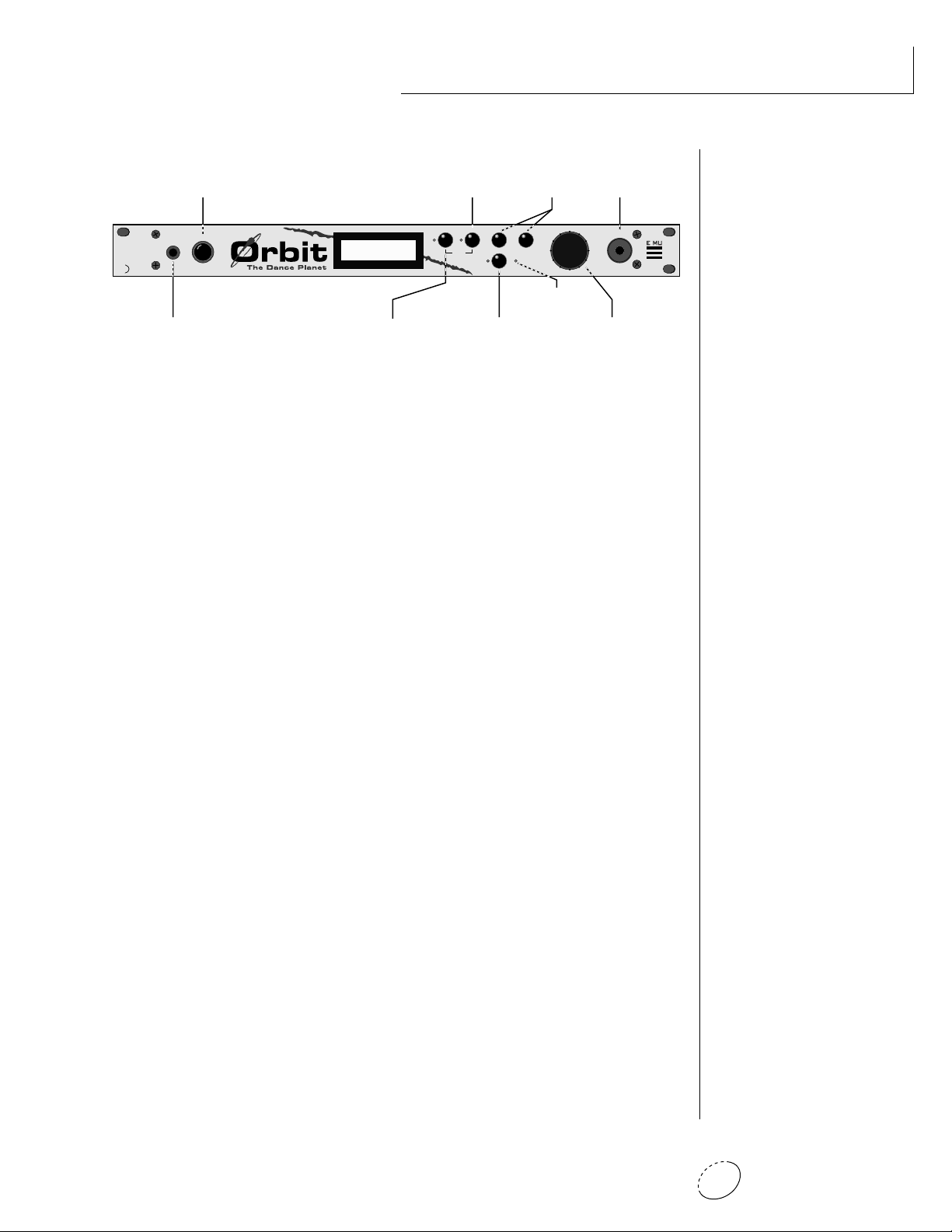
PHONES
VOLUME
C01 Vol127 Pan=P
1
068 vox:Jaxvox
BEATS
HOME/ENTER
CURSOR
MIDI
POWER
DATA
<>
EDITMASTER
ORBITING THE DANCE PLANET - V2
The Dance Planet is a cool place to be. With over 600 of the earth’s
most cutting edge samples and the introduction of new rhythmic
features, Orbit V2 blasts its way to the forefront as the dance music
machine.
Orbit features 32 voices of polyphony, 640 presets (384 ROM, 256
RAM), and is 16 part multi-timbral. Edit and tweak Orbit’s sounds the
way you like them by using its powerful filters, MIDI synced LFO’s,
and MIDIpatch modulation system. If that’s not enough, Orbit is
equipped with plenty of user-editable “beats”. These drum loops aren’t
going to sound like everybody else, Orbit gives you the flexibility to
alter them to fit your style.
INTRODUCTION
Orbit also gives you the ability to literally take these sounds apart and
reassemble them into a limitless number of entirely new sounds,
combining parts of one sound with another or with any of a selection
of digital waveforms also stored in ROM. The dynamic multimode and
morphing filters allow you to shape and mold your sound into new
dimensions. And creating your own sounds is easy, thanks to Orbit's
logical user interface.
Other features include 3 stereo outputs for individually processing
sounds (also configurable as 6 polyphonic submixes with fully programmable dynamic panning), integral sends and returns to allow the
addition of external effects units without the need for a separate
mixer, user definable alternate tuning, and of course, an extensive
MIDI implementation.
In addition, when coupled with E-mu's Launchpad Performance Control-
ler, Orbit becomes a self-contained interactive groove machine for the
stage or studio. Check it out.
All of us at E-mu hope you have as much fun making music with Orbit
as we had making it. And we can't wait to hear the music YOU make
using it.
3Chapter 1: Basic Setup
Page 12
ORBIT ARCHITECTURE
Bank Contents
128 RAM Presets
0
128 RAM Presets
1
128 ROM Presets
2
128 ROM Presets
3
128 ROM Presets
4
Orbit is organized as shown in the diagram below.
INSTRUMENT
PRIMARY
PRESET
SECONDARY
INSTRUMENT
The Preset is a complete set of all program parameters for a complete
Orbit sound. The fully programmable user presets and the unalterable
ROM presets are organized into five banks of 128 presets each.
BANKS 0 & 1 USER PRESETS
BANKS 2 - 4 ROM PRESETS
• User Presets can be
moved, erased or modified as
desired.
• ROM Presets cannot be
moved or altered unless they
are first copied to a user
location.
Each preset consists of one or more instruments. An instrument is a
complete set of samples or a digital waveform which covers the entire
keyboard range. An instrument can be assigned to each of the Primary
and Secondary layers of the preset.
The primary and secondary layers are essentially two complete sounds
stacked or placed adjacent to each other, which can be switched or
crossfaded together in various ways.
Up to four presets can be Linked in order to have more than one preset
on the keyboard at a time. The linked presets may overlap each other
for layered sounds or be adjacent to each other to create keyboard
“splits”.
PRIMARY
PRESET
SECONDARY
PRIMARY
PRESET
SECONDARY
PRIMARY
PRESET
SECONDARY
PRIMARY
SECONDARY
Orbit V2 Operation Manual4
PRESET
Page 13
100-250VAC 50/60 Hz ~
Aux. or
Tape In
MIDI Controller
(MIDI Keyboard, Sequencer, etc.)
Control
Pedal
E-MU SYSTEMS, INC.
Scotts Valley, California U.S.A.
WARNING: TO REDUCE THE RISK OF FIRE
OR ELECTRIC SHOCK, DO NOT EXPOSE
THIS PRODUCT TO RAIN OR MOISTURE.
Male RCA plug
to
Male Phono Plug
MIDI Out
MIDI
To
Main Outs
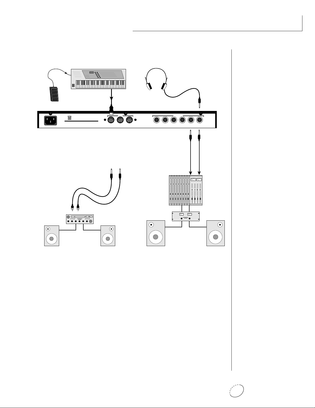
CONNECTION INSTRUCTIONS
SETUP #1 BASIC SETUP
The Headphone
Output is located
on the Front Panel
OUTPUTS
THRUOUTIN
R - SUB2 - L R - SUB1 - L R - MAIN - L
Mixer
Amp
MONO STEREO
Main Outs to Mixer In
▼ The headphone output
monitors the main outputs
only.
The submix outputs do NOT
feed into the headphone
output.
• • • If Orbit does not seem
to be responding correctly,
make sure that both Orbit
and your MIDI controller are
set to the same MIDI channel.
Speakers
Home Stereo
System
Home Studio
System
MIDI In
Orbit is controlled by MIDI messages received at the MIDI In
connector. Connect the MIDI In of the Orbit to the MIDI Out
connector of a MIDI controller such as a MIDI keyboard or MIDI
percussion controller.
Outputs
Orbit is a high quality, stereo audio device. In order to reproduce
its wide dynamic range and frequency response, use a high quality amplification and speaker system such as a keyboard amplifier
or home stereo system. A stereo setup is highly desirable because
of the added realism of stereophonic sound. Headphones can be
used if an amplifier and speaker system is not available. Plug
stereo headphones into the headphone jack located on the left
side of the front panel. The Right Main output jack serves as a
mono output when the Left Main plug is not plugged in.
5Chapter 1: Basic Setup
Page 14
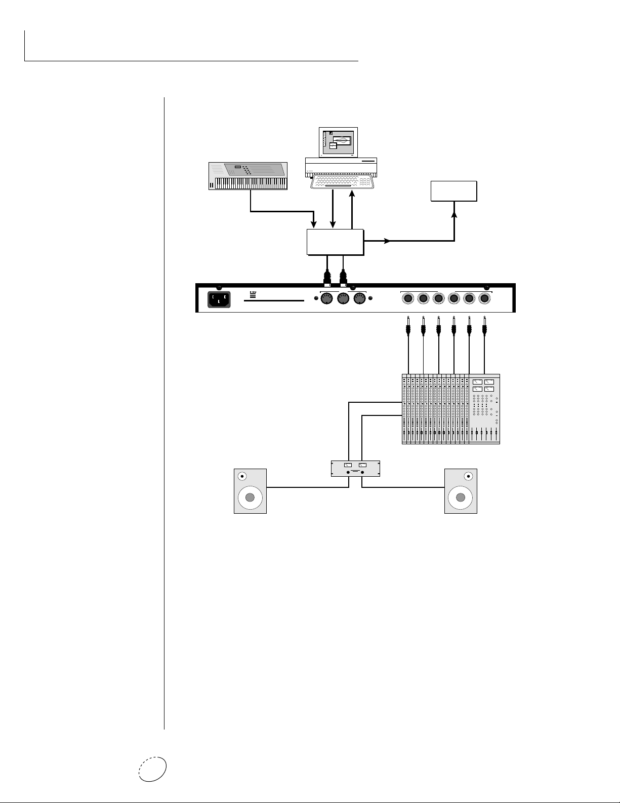
CONNECTION INSTRUCTIONS
SETUP #2 STUDIO SETUP
MIDI Controller
(MIDI Keyboard, Sequencer, etc.)
MIDI Out
Computer
MIDI
Out
MIDI
OutInIn
Additional
MIDI
In
Devices
MIDI In
100-250VAC 50/60 Hz ~
E-MU SYSTEMS, INC.
Scotts Valley, California U.S.A.
WARNING: TO REDUCE THE RISK OF FIRE
OR ELECTRIC SHOCK, DO NOT EXPOSE
THIS PRODUCT TO RAIN OR MOISTURE.
MIDI Switcher
Out In
Out
MIDI
THRUOUTIN
R - SUB2 - L R - SUB1 - L R - MAIN - L
OUTPUTS
Sub 2 Outputs
Sub 1 Outputs
MONO STEREO
Main Outputs
MIDI In
In this setup, Orbit is controlled by MIDI messages received at the
MIDI In connector which have been routed by a MIDI switcher.
The MIDI switcher allows any MIDI controller such as a MIDI
keyboard, MIDI wind controller or a computer to be easily
connected.
MIDI Out
The MIDI Out jack is normally used to transmit program data to a
computer or other device.
Outputs
Orbit has three sets of programmable stereo outputs; Main, Sub 1,
and Sub 2. Specific Orbit presets (or MIDI channels) can be routed
to one of these stereo pairs in order to be further processed or
mixed separately.
Orbit V2 Operation Manual6
Page 15
MIDI Controller
(Launchpad, MIDI Keyboard, Sequencer)
CONTROLLERS
EDIT PARAMETERS TRANSPOSE
C
OFF
C#
-OCT
+OCT
B
INC
SAVESELECT CONTROL
-2OCT
+2OCT
A#
D
D#
A
-3OCT
+3OCT
E
G#
F
G
DEC
F#
PITCH
LAUNCH PAD
PERFORMANCE CONTROLLER
PERFORMANCE SELECT
SONG BANK PRESET
MIDI CLOCK
TRIGGERS
TRANSPORT
MODULATION
13 6810
TRIGGERS/TRANSPORT
RTZMODE
MIDI CHANNEL
1
16
2
15
3
14
4
5
13
6
12
11
7
8
10
9
PLAY
REC
STOPFFWDREW
11975421
MIDI Out
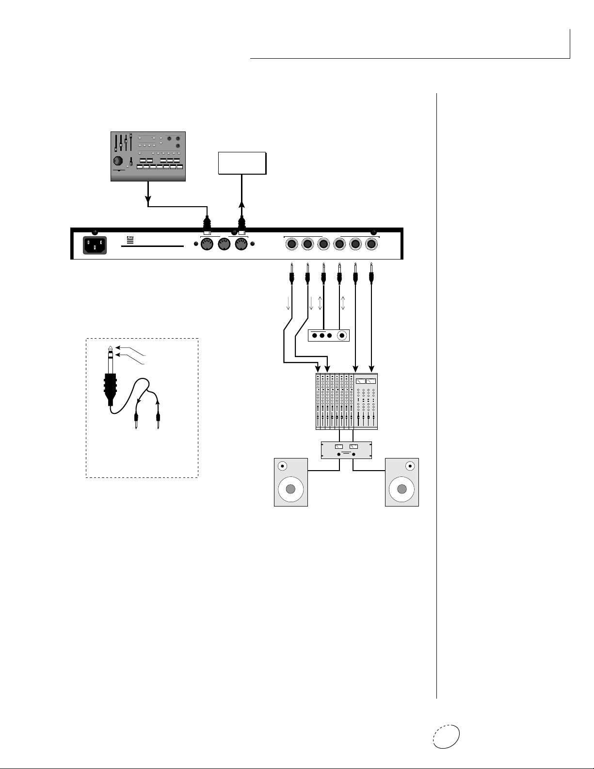
CONNECTION INSTRUCTIONS
SETUP #3 PERFORMANCE SETUP
Additional
MIDI
Devices
MIDI In
E-MU SYSTEMS, INC.
Scotts Valley, California U.S.A.
WARNING: TO REDUCE THE RISK OF FIRE
100-250VAC 50/60 Hz ~
OR ELECTRIC SHOCK, DO NOT EXPOSE
THIS PRODUCT TO RAIN OR MOISTURE.
Sub Output
Return
(To Main Output)
Tip Ring
To Effect From Effect
SEND/RETURN CABLE
Signal is sent out on tip of plug and
returned to main outputs via ring of plug.
MIDI
THRUOUTIN
R - SUB2 - L R - SUB1 - L R - MAIN - L
OUTPUTS
MONO STEREO
Send
Send/Return
Effect Device
Main Outs to Mixer In
MIDI In
Orbit is controlled by MIDI messages received at the MIDI In
connector. Connect the MIDI In of Orbit to the MIDI Out connector of a MIDI controller such as E-mu's Launchpad, a MIDI
keyboard, MIDI drum pads or a MIDI sequencer.
MIDI Thru
The MIDI Thru jack is used to connect additional MIDI devices
onto the MIDI chain. MIDI Thru transmits an exact copy of the
messages received at the MIDI In jack.
Outputs
The Sub 1 and Sub 2 output jacks on Orbit are stereo jacks. The
tip of each jack (accessed when a standard phone plug is inserted)
connects to the left or right output of that group.
7Chapter 1: Basic Setup
Page 16
CONNECTIONS
If a stereo plug is inserted, the Ring of the stereo plug serves as a signal
Return which sums into the Main outputs.
Therefore, the Sub 1 and Sub 2 jacks can serve as effect sends and
returns in order to further process selected instruments and then
return them to the main mix.
••• Inserting a standard
mono phone plug halfway
into the jack allows you to
sum into the main outputs
without a special cable.
The diagram shows the Sub 1 and Sub 2 jacks being used as send/
returns in order to further process selected Orbit presets without using
the effects bus on the mixing board. In a pinch, the effect returns
could also be used to sum additional instruments into the main
outputs.
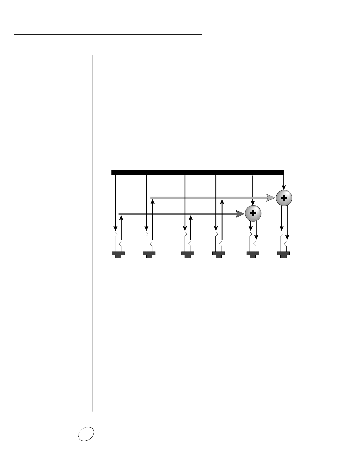
Output Section
L Bus
R Bus
Tip
Tip
Ring
Tip
Ring
RL
SUB 2
Tip
Ring
Ring
RL
SUB 1
RL
MAINS
The Sub 1 and Sub 2 jacks can be used as effect returns to the Main Outputs.
POWER UP!
The power switch is located on the right side of the front panel. Orbit
and its MIDI controller may be turned on in any order. When power is
applied, the liquid crystal display will light, indicating that Orbit is
operating. You may have noticed that there is no 110/220 Volt power
selector switch on Orbit.
ORBIT AUTOMATICALLY SWITCHES ITSELF TO THE
PROPER LINE VOLTAGE.
Orbit V2 Operation Manual8
Page 17
BASIC
OPERATION
Chapter 2: Basic Operation 9
Page 18

BASIC OPERATION
Orbit V2 Operation Manual10
Page 19
MAIN CONTROLS
BASIC OPERATION
VOLUME
CONTROL
VOLUME
PHONES
HEADPHONE
JACK
DISPLAY
C01 Vol127 Pan=P
1
068 vox:Jaxvox
MASTER MENU
SELECT
EDIT MENU
SELECT
EDITMASTER
HOME/ENTER
BEATS
HOME/ENTER
BUTTON
CURSOR
CONTROLS
<>
CURSOR
MIDI
MIDI
ACTIVITY
DATA
DATA ENTRY
CONTROL
Power Switch
Switches AC power to Orbit On and Off.
MIDI Activity LED
Indicates that MIDI data is being received.
Master Menu Select Button
The Master menu contains parameters that affect the entire
machine, not just certain presets. An illuminated LED to the left
of the button indicates that you are in the Master menu.
Edit Menu Select Button
The Edit menu is used when you want to change parameters of a
preset. An illuminated LED to the left of the button indicates that
you are in the Edit menu.
POWER
SWITCH
POWER
Home/Enter Button
The Home/Enter button is used to initiate a particular operation.
The red LED to the left of the enter button flashes to let you know
that Orbit is waiting for your response.
Cursor Controls
These buttons move the cursor to the next parameter on the
display. (The cursor is a little flashing line underneath one of the
parameters in the display.) Press either cursor control repeatedly
until the cursor is underneath the desired parameter. The cursor
can also be moved bi-directionally using the data entry control
while the right cursor select button is being held down (i.e. Press
and hold the right cursor button and turn the data entry knob).
Data Entry Control
The data entry control is a stepped, variable control which is used
to change parameter values. The control increments or decrements the current value one unit with each click. This control
incorporates acceleration (values advance faster if the control is
turned quickly).
Volume Control
This is the master volume control for all audio outputs. Note: For
maximum dynamic range, set this control to full level.
Chapter 2: Basic Operation 11
Page 20
BASIC OPERATION
MIDI CHANNEL SELECTION
Press the cursor key repeatedly untiil the cursor is underneath the
channel number. (The cursor is a little flashing line underneath one of
the parameters in the display.) Rotate the data entry control to select
MIDI channel 01-16. As the channel is changed, the display will
change to show the preset, volume and pan associated with the
displayed channel.
Volume
• • • If Orbit is not respond-
ing properly or plays the
wrong preset, make sure that
both Orbit and your MIDI
controller are set to the same
MIDI channel and that the
MIDI Volume is turned up.
For more information about
MIDI, see MIDI Realtime
Controls on page 52.
Bank Contents
128 RAM Presets
0
128 RAM Presets
1
128 ROM Presets
2
128 ROM Presets
3
128 ROM Presets
4
MIDI Channel
Program No.
C01 Vol127 Pan=P
0
000 Preset Name
Bank No.
Stereo Position
Program Name
PRESET SELECTION
Press the cursor key repeatedly until the cursor is underneath the
program number. (The cursor is a little flashing line underneath one
of the parameters in the display.) As the data entry control is rotated,
the preset number and name will change. The displayed preset will be
assigned to the displayed MIDI channel. Programs are arranged into 5
banks of 128, as shown in the diagram at left. Banks can be selected
independently of the of the program number by pressing the the
Home/Enter button while turning the data entry knob.
C01 Vol127 Pan=P
0 Preset Name
00
MIDI Channel Parameters
Preset Information
••• Channel Pan should
normally be set to “P” unless
realtime control of panning is
desired. This will allow the
programmed pan setting for
each preset to be used.
CHANNEL VOLUME
Press the cursor key repeatedly until the cursor is underneath the
volume value. Rotate the data entry control to select volume 000-127.
(This is the same parameter as MIDI volume control #7, and changes
made over MIDI will be shown in the display.)
CHANNEL PAN
Press the cursor key repeatedly until the cursor is underneath the pan
value. Rotate the data entry control to select pan values -7 to +7 or
“P”. When “P” is selected, the pan value specified in the preset is
selected. Any other value will override the pan parameter in the preset. (This is the same parameter as MIDI pan control #10, and changes
made over MIDI will be shown in the display.)
Orbit V2 Operation Manual12
Page 21

BASIC OPERATION
BEATS MODE
Orbit contains a “Beat Sequencer” which can play any of 100 preprogrammed drum sequences called Beats. Any of Orbit's 640 presets
can be used with any beat. The X-Factor control further multiplies the
number of possible beat combinations by changing which instrument
is assigned to each individual drum hit.
Beats can be also linked together to form Songs. Each song can have up
to 10 steps and each step can be programmed to loop up to 64 times
or loop indefinitely. Each step of a song can select a certain beat
pattern, jump to another step in the song, or jump to the beginning of
another song. Because of this jumping capability, songs can be made
as complex as you like. Orbit holds a maximum of 28 songs which can
be quickly and easily transferred to a MIDI sequencer for backup.
To Enter Beats or Song Mode
1. Press and hold both the Master button and the Edit button. The
Beats menu shown below will appear and the Enter LED will be
flashing.
2. Press the Enter button to Start the beat or song. The Enter LED
will be solidly on and the Master and Edit LEDs will flash once
each time the Beat pattern loops.
3. Press either cursor button and use the data entry control to select
a new beat or song, change the tempo, transpose the sequence
(X-Factor) or change the preset. Song numbers are located
immediately after beat 99.
• • • The Beat number can
be selected remotely by using
a MIDI Song Select command. Beats mode can also
be started and stopped via a
MIDI Song Start and Stop
command when the Beats
screen is displayed.
• • • There are four different
Beats modes: Factory,
1:Constant Tempo,
2:Constant T, X, P
3:User Settings
See page 33 for details.
4. Press the Enter button again to Stop the beat or song.
5. Press and hold both the Master button and the Edit button again
to return to the main screen. The song or beat will continue
playing unless you stopped it using the Enter button. The Master
and Edit LEDs will continue to flash, indicating Beats mode is On.
• To Turn Beats Off - Return to the Beats menu and press Enter.
Beats mode plays the preset assigned to MIDI channel 16. If you are in
Multi-mode, you can play along with beats mode on any of the MIDI
channels.
B:03 T:120 X:+00
492 bts:Danzin
Chapter 2: Basic Operation 13
Page 22
BASIC OPERATION
• • • MIDI Song numbers
(0-127) can select either
Beats (0-99) or Songs
(100-127).
• Beats Mode Parameters
B: Selects the beat number. There are 100 different beats to choose
from.Unless the Master menu Beats mode is set to option 2:Constant T, X, P, the preset will change when you change the beat.
T: Sets the Tempo of the sequence. The tempo is variable from 1 beat-
per-minute to 255 bpm. Turning the tempo all the way down
selects External Clock mode (Ext). In external clock mode, the
tempo is derived from incoming MIDI clock pulses.
X: Selects the “X Factor” or transposition interval. Rather than change
the pitch of the instruments, transposition shifts the keyboard
position up and down. On “Beats” presets this has the effect of
changing the instruments on each beat. By combining the various
beats, presets and transpositions, you can create literally hundreds
of thousands of different grooves. On presets where there is one
sound stretched across the entire keyboard, transpose will
transpose the pitch.
808 Kick
Snare
Chord
Scratch
1 324 1 324
Beat Same Beat
Lawn Mower
Synth Pad
Noise Burst
Deep Kick
Transpose +24
Transposing a “beats” preset shifts the keyboard and changes the sounds assigned to each beat.
SONG MODE
Song mode allows you to link beats together to form more complex
and repeatable song structures. Orbit can record up to 28 songs of up
to 10 events each, numbered E0 through E9.
Tempo
Beat/Song Select
Event No.
S:03 T:120 X:+00
E1 do B23 [01]
X-Factor
No. of Times Played
Event Type
Orbit V2 Operation Manual14
Page 23
• Song Mode Parameters
S: Selects the Song number from S00 to S27. Moving the data entry
control one increment past B99 selects the first Song (S00).
BASIC OPERATION
T & X: The Tempo and X-Factor can be edited for each event, but will
only be saved and recalled if the Beats Mode in the Master
menu is set to 3:User Settings.
E: Selects the Event number. An Event can do one of the following
things:
• Play a particular Beat, a specified number of times.
S:00 T:120 X:+00
E1: do B:05 [10]
• GoTo a Previous Event, a specified number of times.
➜ plays Beat 05, 10 times
S:00 T:120 X:+00
E2: to E1 [04]
• GoTo a particular new Song.
➜ go back to event E1, play 4 times
S:00 T:120 X:+00
E2: to S05 [--]
• Stop the Song.
➜ go to Song S05 NO REPEATS!
• • • See Beats Mode in the
Master Menu for additional
information.
• • • Note: The first Event
in a Song is always a
“Play Beat” Event.
• Song Beats do not have to
begin at event 00. If you
select Event 05 and press
Enter, the Song will begin
playing from event 5.
If the cursor is underneath
the Song number, the Song
will always begin at Event 0.
S:00 T:120 X:+00
E2: Stop [--]
[ ]: Number of times played from 1 to 64. Repeats are not allowed on
GoTo Song or Stop events. Moving the data entry control one
increment past 64 selects Infinite Repeat [<>].
➜ end of Song NO REPEATS!
Chapter 2: Basic Operation 15
Page 24
BASIC OPERATION
Beat 21
Play [01]
E0
Beat 30
Play [01]
E1
Beat 62
Play [01]
E2
GoTo E0
Play [<>]
E3
Infinite Repeat
S22
• Song Examples
Because of the Repeat and Jump functions, Songs can be made as
complex as you like. Remember to set Beats mode (in the Master
menu) to “3:User Settings” if you want the Song to play back your
own Tempo, X-Factor and Preset settings.
The diagrams below show a few examples of how songs can be
constructed.
S21
E0
Beat 07
Play [01]
E1
Beat 18
Play [01]
16 times
E2
GoTo E1
Play [16]
E3
Beat 48
Play [01]
E4
Beat 23
Play [01]
E5
Stop
Play [--]
In the above example, beat 7 plays once, and then beat 18 plays once.
At event E2, the song jumps back and repeats E0 and E1. When events
E0 and E1 have looped 16 times, the song moves on to step E3, E4,
and E5, which stops the song.
In the above example, beats 21, 30 and 62 are simply repeated
indefinitely until you turn off Beat/Song mode.
S23
E0
Beat 02
Play [01]
E1
Beat 51
Play [01]
E2
Beat 40
Play [01]
E3
GoTo S20
Play [--]
E0
S20
Beat 7
Play [01]
etc.
Jump to Song 20
Instead of jumping to a previous step, song 23 jumps to song 20 in the
example above. This technique might be used to add a “lead in” to a
previously stored song.
Orbit V2 Operation Manual16
Page 25
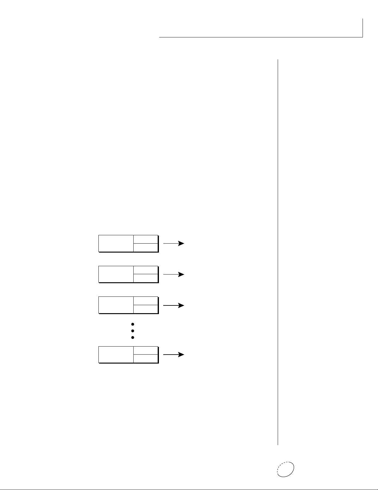
MULTI-TIMBRAL OPERATION
Multi-timbral operation means that Orbit can play more than one
sound at the same time. To access multiple presets on different MIDI
channels simultaneously, follow these instructions:
1. Set the MIDI mode to MULTI-Mode, using the MIDI mode
function in the Master menu (page 24).
2. Decide which MIDI channels you wish the Orbit to receive, and
turn all other channels OFF using the MIDI Enable function in
the Master menu (page 25). Up to 16 channels can be selected
simultaneously!
3. Select the desired preset for each of the MIDI channels you wish
the Orbit to receive using the MIDI Channel/Preset selection
screen (see previous instructions).
4. Orbit will now respond multi-timbrally on the MIDI channels you
have specified. The volume and pan position parameters can be
adjusted over MIDI (for each MIDI channel) or using the Cursor
and Data Entry control in the MIDI Channel/Preset selection
screen.
BASIC OPERATION
Channel 01
Channel 02
Channel 03
Channel 16
Each of the 16 MIDI channels can be assigned to play a specific Orbit preset.
Volume
Pan
Volume
Pan
Volume
Pan
Volume
Pan
PRESET
PRESET
PRESET
PRESET
Chapter 2: Basic Operation 17
Page 26
BASIC OPERATION
ABOUT ORBIT
Orbit utilizes digital recordings of real instruments for the basis of its
sound. This is similar to a tape recorder except that inside the Orbit,
the sounds are permanently recorded on digital memory chips.
To perform this modern miracle, sounds and instrument waveforms
are first digitally recordered or “sampled”. After the sounds and
waveforms have been truncated, looped and processed, they are
“masked” into the Orbit ROM (Read Only Memory) chips.
Conceptually, the sampling process is very simple, as shown in the
Basic Sampling System diagram. As a sound wave strikes the
diaphragm of a microphone, a corresponding voltage is generated. To
sample the sound, the voltage level is repeatedly measured at a very
high rate and the voltage measurements are stored in memory. To play
the sound back, the numbers are read back out of memory, converted
back into voltages, then amplified and fed to a speaker which converts
the voltage back into sound waves. Of course, playing back 32
channels at different pitches tends to complicate matters, but this is
basically how it works. In Orbit, we have left out the Analog/Digital
converter stage since the sounds are already sampled for you.
Analog/Digital
Converter
1011001
1011001
Basic Sampling System
Orbit
Memory
10100101001
01010010100
10101010100
10101001010
Z-Plane Filter Amplifier
3V
0V
-3V
Digital/Analog
Converter
1011001
-1V -2V3V-1V-2V3V1V
Orbit V2 Operation Manual18
Page 27
MASTER
MENU
Chapter 3: Master Menu 19
Page 28

MASTER MENU
Orbit V2 Operation Manual20
Page 29

The Master menu contains functions that affect the overall operation
of Orbit. For example, changing the Master Tune will change the
tuning of all the presets, not just the one currently displayed.
To enable the Master menu
Press the Master key, lighting the LED. The current screen will be
the one most recently selected since powering up Orbit. The
cursor will appear underneath the first character of the screen
heading on line one.
To select a new screen
Press the cursor key repeatedly (or hold the right cursor key while
turning the data entry control) until the cursor is underneath the
screen title heading. Rotate the data entry control to select an-
other screen.
To modify a parameter
Press the cursor key repeatedly (or hold the right cursor key while
turning the data entry control) until the cursor is underneath the
parameter value. Rotate the data entry control to change the
value.
MASTER MENU
To return to Preset Select mode
Press the Master key, turning off the LED.
MASTER MENU FUNCTIONS
• Master Tune
Master Tune adjusts the overall tuning of all presets so that Orbit can
be tuned to other instruments. The master tuning range is ± 1
semitone in 1/64th semitone increments. A master tune setting of
“00” would indicate that the Orbit is perfectly tuned to concert pitch
(A=440 Hz).
MASTER TUNE
+63
Chapter 3: Master Menu 21
Page 30
MASTER MENU
• Transpose
This function transposes the key of Orbit in half-step intervals by
shifting the keyboard position relative to middle C.. The transpose
range is ± 12 semitones or one octave.
TRANSPOSE
+12 semitones
• Global Bend
This function sets the range of the pitch wheel only when it is routed
to control pitch. The maximum pitch bend range is ± 12 semitones.
This function only affects presets which have their individual pitch
bend range set to global.
GLOBAL BEND
+/- 12 semitones
• Global Velocity Curve
Incoming velocity data can be modified by a velocity curve in order to
provide different types of dynamics in response to your playing or to
better adapt to a MIDI controller. This function allows you to select
one of eight global velocity curves or leave the velocity data unaltered
(off). Global velocity curve only affects presets which have their
individual velocity curve set to global.
GLOBAL VEL CURVE
8
Orbit V2 Operation Manual22
Page 31

GLOBAL VELOCITY CURVES
MASTER MENU
120
100
80
60
40
20
Result Velocity
Curve 1
0
20
0
40
Played Velocity
120
100
80
60
40
20
Result Velocity
0
20
0
40
Played Velocity
60
60
100
80
Curve 3
100
80
120
120
120
100
80
60
Curve 2
40
20
Result Velocity
0
20
0
40
Played Velocity
120
100
80
60
40
20
Result Velocity
0
20
0
40
Played Velocity
60
60
100
80
Curve 4
100
80
120
120
120
100
80
60
40
20
Result Velocity
0
20
0
40
Played Velocity
120
100
80
60
40
20
Result Velocity
0
20
0
40
Played Velocity
60
60
Curve 5
100
80
Curve 7
100
80
120
120
120
100
80
60
40
20
Result Velocity
0
20
0
40
Played Velocity
120
100
80
60
40
20
Result Velocity
0
20
0
40
Played Velocity
60
60
Curve 6
100
80
Curve 8
100
80
120
120
Chapter 3: Master Menu 23
Page 32

MASTER MENU
••• This function is useful
when sequencing because it
allows you route specific
MIDI channels to the Submix
outputs. From there they can
be externally processed with
reverb or other effects.
• Mix Output
This function allows you to override the output assignments made in
each preset and instead assign the outputs according to MIDI channel.
This also allows you to change the output assignment of the factory
presets. For each of the 16 MIDI channels, you can select the Main,
Sub 1, or Sub 2 outputs, or “P”. When “P” is selected, the output
assignment selected in the preset is used. If no plugs are inserted into
the sub outputs, the audio will be automatically directed to the main
outputs.
MIX OUTPUT
channel 01:P
• MIDI Mode
This function selects one of the four MIDI modes and the MIDI system
exclusive ID number.
▼ Warning: Presets can not
be transferred between two
Orbit units unless the ID
numbers of both units
match.
Omni mode
Orbit responds to note information on all MIDI channels and
plays the preset currently displayed in the main screen.
Poly mode
Orbit only responds to note information received on the currently selected MIDI channel (on the preset selection screen) and
plays that channel’s associated preset.
Multi mode
Orbit responds to data on any combination of MIDI channels and
plays the specific preset associated with each of the MIDI channels.
Mono mode
Orbit responds to data on any combination of MIDI channels but
plays each channel monophonically. If a new note on a channel
is played before the last note is released, the envelopes will not be
retriggered (legato).
ID number
This function allows an external programming unit to distinguish
between multiple Orbit units. In this case, each unit should have
a different ID number.
MIDI MODE ID
Omni 00
Orbit V2 Operation Manual24
Page 33

• MIDI Mode Change
This function selects whether or not MIDI mode change commands
are accepted or ignored when received over MIDI (see MIDI Mode).
MIDI MODE CHANGE
Disabled
• MIDI Overflow
When on, if you play more notes than Orbit has channels (32), the
additional note data will be directed out the MIDI Out port to a second Orbit, thus doubling the number of available channels. MIDI
Overflow can be turned On or Off.
MIDI OVERFLOW
Off
MASTER MENU
• MIDI Enable
When in MIDI Multi mode, this function lets you turn each MIDI
channel On or Off. This is useful when you have other MIDI devices
connected and do not want the Orbit to respond to the MIDI channels
reserved for the other devices. MIDI Enable only operates in Multi
Mode.
MIDI ENABLE
channel 01: On
• MIDI Bank Select
The MIDI specification only allows for 128 presets per MIDI channel.
This function selects which bank of 128 presets will be used for
incoming MIDI program change commands. Banks can be set for each
MIDI channel. This function allows you to access all 640 presets in
Orbit without using a MIDI bank select command.
MIDI BANK
channel 01:1
MIDI Preset Bank
MIDI Channel
Chapter 3: Master Menu 25
Page 34

MASTER MENU
• MIDI Program ➔ Preset
Incoming MIDI program changes can be “mapped” to call a different
numbered preset. This is a handy feature when you want a specific
preset number sent from the master synth to be linked with a specific
preset on Orbit. For example, the Program ➔ Preset Map could be set
to call up preset 12 whenever Orbit receives program change number
26. Any of the presets in Orbit can be mapped to any incoming MIDI
program change number. This feature also allows you to select presets
in banks 1-4, which are not normally accessible over MIDI without
sending bank change commands.
Note: The MIDI Program->Preset Map only works when you are in
Bank 0.
Selected
Program
MIDI PROG>PRESET
026 –> 012
0 1 2 3 4 5 6 7 8 9
0000000000
00 01 02 03 04 05 06 07 08 09
201000 0 0
44 91 50 01 15 88 99 78 32 88
10
10002000 02
34 73 106 55 43 75 120 121 100
20
0000000000
30 31 32 33 34 35 36 37 38 39
30
0000000000
40 41 42 43 44 45 46 47 48 49
40
0000000000
50 51 52 53 54 55 56 57 58 59
50
0000000000
60 61 62 63 64 65 66 67 68 69
60
0000000000
70 71 72 73 74 75 76 77 78 79
70
0000000000
80 81 82 83 84 85 86 87 88 89
80
0000000000
90 91 92 93 94 95 96 97 98 99
90
0000000000
100 101 102 103 104 105 106 107 108 109
100
110
120
0000000000
110 111 112 113 114 115 116 117 118 119
00000000
120 121 122 123 124 125 126 127
12
0
41
Mapped
Program
This chart shows how MIDI preset changes can be re-mapped. In this example, program
changes 10-29 have been re-mapped. All other programs will be selected normally.
Orbit V2 Operation Manual26
Page 35

• Preset Change
This function lets the Orbit utilize or ignore incoming MIDI preset
change or Bank Select commands for each channel. Note that a MIDI
program change command can only select presets in bank 0. The
presets in banks 1-4 can be selected manually, by changing the MIDI
bank, by using a MIDI bank select command, or by using the mapping
function “MIDI PROGRAM ➙ PRESET”.
PRESET CHANGE
channel 01: On
• MIDI Controller Assign
Orbit allows you to assign up to four realtime control sources from
your MIDI controller. These control sources could be modulation
wheels, data sliders or whatever. In this screen, you set up which
controllers will be received by Orbit. What effect the controller will
have is programmed separately for each preset. The Orbit MIDI controllers are each assigned a letter, A-D. Each controller letter can be
assigned to a MIDI realtime controller from 00-31. Note: If controller
numbers 7 or 10 are selected, they will override the standard MIDI
volume and pan control routings.
CONTROLLER# ABCD
01 02 03 04
MASTER MENU
••• A few of the standardized MIDI Controller
numbers are listed below.
1 - Modulation Wheel
2 - Breath Controller
3 - Aftertouch
4 - Foot Pedal
5 - Portamento Time
6 - Data Entry
7 - Volume
8 - Balance
9 - Undefined
10 - Pan
11 - Expression
••• For more information on
controller assignments, see
MIDI Realtime Controls in the
Programming Basics section.
• X Factor Control
This function allows any MIDI controller number from 0-31, mono
pressure, or the pitch wheel to change the X Factor (transpose) of
Beats mode. Two controllers can be assigned to move the X Factor
both up and down from its initial position. With a wheel assigned to
the up control, moving the wheel up adds a positive offset to the X
Factor setting. Moving the wheel back down returns the X Factor to its
original setting. The maximum controller offset is ±36, which is added
to the initial setting. The pitch wheel (pwh) can be assigned to both
up and down settings to allow bidirectional control. When “Off” is
selected, external control of X Factor is disabled. This controller is
only recognized on MIDI channel 16, unless Orbit is in Omni mode,
in which case all channels are accepted.
X FACTOR CONTROL
up:14 down:15
Chapter 3: Master Menu 27
••• The X Factor, Tempo
Control and Scratch settings
are sent and received with
the Master Settings.
See Send MIDI Data.
••• When X Factor Control is
being used, the last setting of
the MIDI controller remains
in effect when a new Beat is
selected.
Page 36

MASTER MENU
••• When Tempo Control is
being used, the last setting of
the MIDI controller remains
in effect when a new Beat is
selected.
▼ When the Global Tempo is
set to “External” , the Tempo
Control parameter will not
have any effect.
• Tempo Control
This function allows MIDI controllers to change the Global Tempo
which is used for Beats mode, Retrigger, and the synced LFOs. Any
controller number from 0-31, mono pressure, or the pitch wheel can be
assigned to change the Global Tempo. A different controller can be
used to change the tempo up or down. The Pitch Wheel can be
assigned to both the up and down parameters to vary the tempo up
and down from a single controller. MIDI Controller values are added to
the Global Tempo with an offset range of ±64. When the controller is
set to zero (off) the tempo returns to its original setting. This controller
is only recognized on MIDI channel 16, unless Orbit is in Omni mode,
in which case all channels are accepted. This control has no effect
when external clock is being used.
TEMPO CONTROL
up:pwh down:pwh
••• When a MIDI controller
is used to control Retrigger,
the last setting of the MIDI
controller remains in effect
when a new Preset or Beat is
selected.
▼ When the Global Tempo is
set to “External” , the 1/64th
note divisor is not possible.
1/64 T will be substituted,
even though the display
reads 1/64.
• Retrigger
The Retrigger function creates a “stuttering” effect by resetting the
sample start point and envelope generators to their starting point every
time a trigger is received. The rate of retriggering is based on the Global
Tempo which is divided down by the Retrigger Rate parameter. A MIDI
continuous controller (0-31 or Mono Pressure) can also be assigned to
control the Global Tempo divisor. Set the rate parameter to “Off” to
disable retriggering.
RETRIGGER
ch:01 rate:1/16
The following Retrigger divisors are available:
Dbl - Double Whole Notes
Dbl T - Double Whole Note Triplets
Whole - Whole Notes
Whl T - Whole Note Triplets
Half - Half Notes
Half T - Half Note Triplets
1/4 - Quarter Notes
1/4 T - Quarter Note Triplets
1/8 - Eighth Notes
1/8 T - Eighth Note Triplets
1/16 - Sixteenth Notes
1/16 T - Sixteenth Note Triplets
1/32 - Thirty-second Notes
1/32 T - Thirty-second Note Triplets
1/64 - Sixty-fourth Notes
1/64 T - Sixty-fourth Note Triplets
Orbit V2 Operation Manual28
Page 37

• Pitch Wheel -> Scratch
This function allows the pitch wheel to simulate record scratching.
When this function is On, the speed that you move the pitch wheel
back and forth determines the pitch of the keys being played. Therefore the faster you move the wheel back and forth, the faster the
sound plays through. The amount of control the wheel has is adjustable from 1 to 100. Adjust the amount depending on the type of
sound being scratched and to suit your personal preference. Scratch
can be assigned to any MIDI channel from 1-16 or to “All” channels.
Setting the channel to “None” turns scratch mode off.
PITCH WH->SCRATCH
ch:01 amt:50
MASTER MENU
• MIDI Footswitch Assign
Like the MIDI Controllers, 3 MIDI footswitches can be assigned to
MIDI footswitch numbers. Footswitches can be assigned numbers from
64-79. Destinations for the footswitch controllers are programmed in
the Edit menu.
FOOTSWITCH #
1:64 2:65 3:66
••• A few of the standardized MIDI switch numbers
are listed below.
64 - Sustain Switch (on/off)
65 - Portamento (on/off)
66 - Sostenuto (on/off)
67 - Soft Pedal (on/off)
69 - Hold Pedal 2 (on/off)
Chapter 3: Master Menu 29
Page 38

MASTER MENU
• Send MIDI Data
This function will send MIDI System Exclusive data to the MIDI Out
port of Orbit. The MIDI data can either be sent to a computer,
sequencer or to another Orbit. Using the cursor key and the data entry
control, select the type of MIDI data you wish to transmit.
User Beat Data
Transmits all User Beat data (tempos, X factor, preset) and all user
Song Beat data (events, repeats, jumps).
••• The Preset, Volume, and
Pan information for all 16
channels is included when
the Master settings are
transmitted or received.
▼ Warning: When transfer-
ring SysEx data from one
Orbit to another, the ID
numbers of both units must
match.
Master Settings
Transmits all parameters in the Master menu except tuning table,
program/preset map and viewing angle.
Program/ Preset Map
Transmits only the program/preset map.
Tuning Table
Transmits only the user tuning table.
Factory Presets
Transmits all the factory ROM presets.
User Presets
Transmits all the user presets.
Any Individual Preset
Transmits only the selected preset.
The Enter LED will be flashing. Press the Enter button to confirm the
operation. To receive MIDI data, simply send the MIDI data into Orbit
from another Orbit or your sequencer.
SEND MIDI DATA
000 Stereo Piano
To Record MIDI Data into a Sequencer:
1. Setup sequencer to receive system exclusive data.
2. Place sequencer into record mode, then Send Preset Data.
To Receive MIDI Data from a Sequencer:
1. Simply play back the sequence into Orbit.
▼ Warning: Send data as you would a regular sequence. Sending data
in one huge chunk may clog the MIDI input buffer on Orbit.
Orbit V2 Operation Manual30
Page 39

• Beats MIDI Out
This function allows Beat note and controller data to be sent out
MIDI as the Beats are playing. Selecting “Transmit” sends the MIDI
data as the beats play. Selecting “Transmit & Mute” sends the data
over MIDI data but does not play internal voices.
BEATS MIDI OUT
Transmit
• User Key Tuning
In addition to standard twelve tone equal temperament, Orbit contains four additional preset tuning tables (Just C, Vallotti, 19 tone, and
Gamelan) and one user definable tuning. User Key Tuning allows you
to alter the parameters of the user definable tuning. The pitch of every
key can be individually tuned, facilitating the creation of alternate
scales. Using the cursor key and the data entry control, select the key
name, the MIDI key number and the fine tuning. The key name is
variable from C-2 to G8. MIDI key number is variable from 0 to 127.
The fine tuning is variable from 00 to 63 in increments of 1/64 of a
semitone (approx. 1.56 cents). For each preset, the specific tuning
table is selected in the Edit menu.
MASTER MENU
••• The Beats MIDI Out
settings are sent and received
with the Master Settings.
See Send MIDI Data.
USER KEY TUNING
Key Name
Key:C1 036-00
Fine Tuning
Coarse Tuning
• Song Start/Stop
This function enables or disables MIDI Song Start/Stop for Beats mode.
In some cases you may want to start Beats mode along with an
external sequencer. In other cases you may want to start Beats mode
independently. This control allows you either option. Song Select or
MIDI clocks are not affected by this function. You can also use the
Beats Control number (see the following page) to control Song Start/Stop
even when this function is disabled.
SONG START/STOP
Enabled
••• Application: The user
key tuning can be used to
tune individual percussion
instruments.
Chapter 3: Master Menu 31
Page 40

MASTER MENU
▼ When the Global Tempo is
set to “External” , the Tempo
Control parameter will not
have any effect.
• Global Tempo
This function sets the tempo for Beats mode, Synced LFOs and the
Retrigger features. This tempo setting is the same as shown in Beats
mode and any changes you make will be shown in either window. The
global tempo is variable from 1 beat-per-minute (bpm) to 255 bpm.
Turning the tempo down below 1 bpm sets the tempo to “External”
mode. In external mode, the tempo is determined by incoming MIDI
clocks. Note that in external clock mode, the Beat will not start if
there is no incoming MIDI clock to set the tempo.
GLOBAL TEMPO
120 bpm
• Beats Control
This function allows you to control Beats mode using standard MIDI
Note-on messages. The selectable options are: “Mute Key”, “Start Key”,
and “Stop Key”. The Mute Key, while pressed, silences the beat or song
without stopping it and also silences MIDI transmission of beats. Any
MIDI key number can be assigned to the three controls, but they must
be received on MIDI channel 16 to be recognized unless Orbit is in
Omni mode, in which case all channels are accepted. These keys only
work when the beats screen is displayed.
BEATS CONTROL
Mute Key: C6
Start Key
Stop Key
C-2 C-1 C0 C1 C2 C3 C4 C5 C6 C7 C8
= Standard 5 Octave Keyboard Range
Control keys can be placed out of the way at the ends of the keyboard or anywhere you prefer.
Mute Key
Orbit V2 Operation Manual32
Page 41

• Beats Mode
There are four options when in Beats mode: Factory Settings, Constant
Tempo, Constant T, X, P and User Settings. These modes affect the
way Orbit responds to parameter changes in Beats Mode. The
characteristics of each mode are detailed below.
Factory Settings........ The Tempo, X Factor (transpose) and Preset are
preset at the factory. These can be changed, but
any changes are lost when the beat number is
changed.
1:Constant Tempo .... The Factory settings of Preset and X Factor will
be used whenever a new beat is selected, but the
Tempo can be user-adjusted and will remain
constant when new beats are selected.
2:Constant T, X, P..... Tempo, X Factor and Preset are user-adjustable
and will remain constant when new beats are
selected.
MASTER MENU
3:User Settings ......... All Beat parameters (Tempo, X-Factor, Preset) are
user-adjustable and are immediately saved to
non-volatile RAM. These user settings remain
stored in RAM even if another Beats mode (such
as factory settings) has been selected.
BEATS MODE
Factory Settings
• Demo Sequence
Orbit contains a play-only demo sequencer to give you an idea of
what is possible using this fantastic machine. Press either cursor key to
move the cursor to the lower line of the display and press Enter. The
Demo Select screen will appear and the first sequence will begin playing. The two sequences play one after the other and will continue to
repeat. Use the cursor keys to select a particular sequence. Pressing the
Enter button again will stop the sequence and return you to the first
Demo screen.
DEMO SEQUENCE DEMO 1 2
Start ENTER=Stop >=Next
Chapter 3: Master Menu 33
Page 42

MASTER MENU
• Viewing Angle
This function allows you to change the viewing angle of the display so
that it may be easily read from either above or below. The angle is
adjustable from +7 to -8. Positive values will make the display easier to
read when viewed from above. Negative values make the display easier
to read from below.
VIEWING ANGLE
+7
Orbit V2 Operation Manual34
Page 43

PROGRAMMING
BASICS
Chapter 4: Programming Basics 35
Page 44

PROGRAMMING BASICS
Orbit V2 Operation Manual36
Page 45

PROGRAMMING BASICS
This chapter explains how Orbit sounds are constructed and contains
important background information on how to create your own custom presets.
Your initial involvement with Orbit will most likely consist of using
the existing presets and selecting MIDI channels. While the factory
presets are very good, there are probably some things you would like
to change, perhaps the LFO speed, the filter cutoff or the attack time.
You may also want to make your own custom presets using complex
modulation routings. There are 256 user locations (Banks 0 & 1)
available to store your own creations or edited factory presets. Best of
all, it’s easy to edit or create new presets using the edit menu.
Presets can be made up of both a primary and secondary instrument.
Presets can also be “linked” with up to 3 additional presets to create
layering or splits.
One way to create a keyboard split is assign an instrument to a specific
range and then link it to other presets which fill in the empty keys.
Using a combination of 4 linked presets and the primary and secondary instrument ranges, up to 8 keyboard splits can be produced. If
linked presets overlap on the same keyboard range, the presets will be
doubled or stacked.
LINK
Key Range
Key Range
CREATING A SPLIT KEYBOARD
Key Range
Zone 1
Zone 2
Preset #1
Preset #2
LAYERING TWO PRESETS
These diagrams show how keyboard splits and layers can be created by linking presets.
Remember that each preset can consist of both a primary and secondary instrument.
Chapter 4: Programming Basics 37
Page 46

PROGRAMMING BASICS
Orbit has an extensive modulation implementation using two multiwave LFO’s (Low Frequency Oscillators), two envelope generators and
the ability to respond to multiple MIDI controllers. You can simultaneously route any combination of these control sources to multiple
destinations.
MODULATION
Modulation means to dynamically change a parameter, whether it be
the volume (amplitude modulation), the pitch (frequency modulation), or whatever. Turning the volume control on your home stereo
rapidly back and forth would be an example of amplitude modulation.
To modulate something we need a modulation source and a modulation destination. The source is your hand turning the knob, and the
destination is the volume control. If we had a device that would
automatically turn the volume control, we would also call that device
a modulation source. Orbit is designed so that for each of the variable
parameters, such as the volume, there is an initial setting which can
be changed by a modulation source. Therefore in the case of volume,
we have an initial volume and we can change or modulate that
volume with a modulation source. Two main types of modulation
sources on Orbit are Envelope Generators and Low Frequency Oscillators.
In the example above, an envelope generator could be routed to
automatically turn the volume control as programmed by the envelope. Or, a low frequency oscillator could be routed to automatically
turn the volume control up and down in a repeating fashion.
Turning the volume control back and forth on your home stereo is an example of
Amplitude Modulation.
Orbit V2 Operation Manual38
Page 47

PROGRAMMING BASICS
MODULATION SOURCES
Orbit uses three kinds of modulation sources.
• KEYBOARD AND VELOCITY MODULATION
Values which are generated at the start of a note and do not change
during the note.
Keyboard Key
Which key is pressed.
Key Velocity
How hard the key is pressed.
• REALTIME MODULATION
Values which can be continuously changed during the entire duration
of the sound.
Pitch Wheel
A synthesizer pitch bend wheel.
Miscellaneous Controllers (4)
Any type of MIDI controller data.
Keyboard Pressure (mono aftertouch)
Key pressure applied after the key is initially pressed.
Polyphonic Key Pressure
Pressure from a controller capable of generating polyphonic
pressure data.
Low Frequency Oscillators (2)
Generate repeating waves.
Envelope Generators (3)
Generate a programmable “contour” which changes over time
when a key is pressed.
• FOOTSWITCH MODULATION
Changes a parameter when one of the three footswitches are pressed.
The footswitches can be programmed to switch: Sustain (pri/sec/both),
Alternate Volume Envelope (pri/sec/both), Alternate Volume Release
(pri/sec/both), or Cross-Switch between the primary and secondary
instruments.
Chapter 4: Programming Basics 39
Page 48

PROGRAMMING BASICS
ENVELOPE GENERATORS
An envelope can be described as a “contour” which can be used to
shape the sound in some way over time. Each channel of the Orbit
contains two envelope generators. One of the envelope generators, the
Alternate Volume Envelope, controls the volume of the primary or
secondary instrument over time and has 5 stages, Attack, Hold, Decay,
Sustain, and Release. The other envelope, the Auxiliary Envelope, can
be routed to any realtime control destination and is a general purpose
envelope. The Auxiliary Envelope has 6 stages: Delay, Attack, Hold,
Decay, Sustain, and Release. The time of each stage can be adjusted to
create myriad envelope shapes, which in turn shape the sound. The
Envelope parameters can be described as follows:
Percussion
Organ
String
Plucked
••• The generalized envelope
shapes of a few types of
sounds are shown above.
• Delay
The time between when a key is played and when the attack
phase begins.
• Attack
The time it takes to go from zero to the peak (full) level.
• Hold
The time the envelope will stay at the peak level before starting
the decay phase.
• Decay
The time it takes the envelope to go from the peak level to the
sustain level.
• Sustain
The level at which the envelope remains as long as a key is held
down.
• Release
The time it takes the envelope to fall to the zero level after the
key is released.
level
Orbit V2 Operation Manual40
time
D
e
a
y
key
down
Sustain
A
t
l
t
a
c
k
H
o
l
d
D
e
c
a
y
key
released
R
e
l
e
a
s
e
Page 49

level
PROGRAMMING BASICS
time
AHR
key
down
If the key is released during the Hold (H) phase, the Release phase begins.
key
released
LOW FREQUENCY OSCILLATORS (LFOS)
A Low Frequency Oscillator is simply a wave which repeats at a slow
rate. The Orbit has two multi-wave LFOs for each of its 32 channels.
The LFO waveforms are: Triangle, Sine, Square, Sawtooth, and Random, which is a random “sample and hold” type of wave. Other LFO
waves are “Synced” which means that their rates will follow the tempo
as set in Beats mode.
By examining the diagram of the LFO waveforms, you can see how the
LFO will affect a modulation destination. Suppose we are modulating
the pitch of an instrument. The sine wave looks smooth, and will
smoothly change the pitch. The square wave changes abruptly, and
will abruptly change the pitch from one pitch to another. The
sawtooth wave smoothly decreases, then abruptly changes back up.
The sound’s pitch will follow the same course. Controlling the pitch
of an instrument is an easy way to hear the effects of the LFO waves.
Triangle
Sine
Square
Sawtooth
Random
Chapter 4: Programming Basics 41
Page 50

PROGRAMMING BASICS
When the amount of an LFO is a negative value, the LFO shape will be
inverted. For example, inverting the sawtooth wave produces a wave
that smoothly increases, then instantly resets down.
Negative Amount
+-
Sawtooth
Inverted Sawtooth
The LFO can also be Synced the tempo programmed in the beats
menu. When synced, the LFO rate will increase or decrease to follow
the beats/global tempo.
MIDIPATCH
Connecting a modulation source to a destination is called a patch.
Orbit lets you connect the modulation sources in almost any possible
way to the modulation destinations. You can even modulate other
modulators. Each patch also has an amount parameter which determines “how much” modulation is applied to the destination. The
modulation amount can be positive or negative and will either add or
subtract from the initial value. Keyboard and velocity sources can be
simultaneously patched to any 6 of the 42 destinations for each preset.
Realtime modulation sources can be simultaneously patched to any 8
of the 33 destinations for each preset.
Amount +/-
Modulation
Source
+-
Destination
LFO 1
Sources
LFO 1
LFO 2
Aux Env
Wheel
Pressure
MIDI
etc.
Orbit V2 Operation Manual42
Primary
Volume
Destinations
Pitch
X-Fade
Volume
LFO Amt.
Filter Fc
Attack
etc.
Page 51

FILTER MODULATION
Orbit contains a Z-plane filter for each of its 32 channels. The block
diagram of a single channel is shown below.
PROGRAMMING BASICS
Instrument
Sample
Pitch
Start
Tone
Morph Q
Aux.
DAHDSR
Z-Plane
Filter
Velocity
DCA
Volume
Volume
AHDSR
Pan
R
L
The Tone filter is a simple tone control and can be used to brighten
or darken the tone of an instrument. Each of the 17 Z-plane filters is a
powerful synthesizer filter which can dramatically alter the sound of
an instrument.
WHAT IS A FILTER?
To understand how a filter works we need to understand what makes
up a sound wave. A sine wave is the simplest form of sound wave. Any
waveform except a sine wave can be analyzed as a mix of sine waves at
specific frequencies and amplitudes.
One way to represent complex waveforms is to use a chart with frequency on one axis and amplitude on the other. Each vertical line of
the chart represents one sine wave at a specific amplitude.
Amplitude
40 80 160 360 720 1440 2880
Frequency
Chapter 4: Programming Basics 43
Page 52

PROGRAMMING BASICS
20
40
60
80
100
40 80 160 360 720 14402880
Frequency
...
Amplitude
Output of Filter
Cutoff Frequency
••• The initial filter Fc and
all Fc modulators ADD
algebraically to determine
the actual Fc. If you are not
getting sound, adjust the
initial Fc or reduce the
amount of modulation.
Careful adjustment of all the
filter parameters is the secret
to getting great sounds.
Most of the instruments in Orbit are complex waves containing many
sine waves of various amplitudes and frequencies. A filter is a device
which allows us to remove certain components of a sound
depending on its frequency. For example, a Low Pass Filter, one of
the Z-plane filters in Orbit, lets the low frequencies pass and removes
only the high frequencies.
The point at which the frequencies begin to be cut is called the Cutoff
Frequency (or Fc for short). A filter that let only the high frequencies
pass would be called a High Pass filter. Using a filter, we now have a
way to control the harmonic content of a sampled sound. As it turns
out, a low pass filter can simulate the response of many natural
sounds.
For example, when a piano string is struck by its hammer, there are
initially a lot of high frequencies present. If the same note is played
softer, there will be fewer of the high frequencies generated by the
string. We can simulate this effect by routing the velocity of the
keyboard to control the amount of high frequencies that the low pass
filter lets through. The result is expressive, natural control over the
sound.
The auxiliary envelope generator is commonly used to control the
cutoff frequency of the Z-plane filter. This allows the frequency
content to be varied dynamically over the course of the note.
Dynamic filtering coupled with all the different instruments available,
makes for almost endless possibilities in the final sound. Any modulation source can be used to modulate the filter.
Orbit V2 Operation Manual44
Page 53

PROGRAMMING BASICS
Another control on the filter is called Q or resonance. On a lowpass or
highpass filter, turning up the Q of the filter emphasizes the frequencies around the cutoff frequency. The chart below shows how different
amounts of Q affect the lowpass filter response. In terms of sound,
frequencies around the cutoff will tend to “ring” with high Q settings.
If the filter is swept back and forth slowly with a high Q, various
overtones will be “picked out” of the sound and amplified as the
resonant peak sweeps over them. Bells and gongs are real world
examples of sounds which have a high Q.
Low Q Med Q High Q
Amplitude
Frequency
Turning up the “Q” will emphasize the frequencies around the cutoff point.
Another important feature of a filter is the number of poles it contains. The lowpass filters on Orbit can be either 2-pole, 4-pole or
6-pole filters. The highpass and bandpass filters can be either 2nd or
4th order filters another way to describe the number of filter sections
they contain. The number of poles in a filter describes the steepness of
its slope and the more poles the steeper the slope, which in turn
affects the sound. In general, the 2-pole filter will have a buzzier
sound and a 4-pole filter has the classic low pass resonant filter sound.
Orbit's 6-pole low pass filters have a tight, modern sound.
Amplitude
4-pole
2-pole6-pole
Frequency
Chapter 4: Programming Basics 45
Page 54

PROGRAMMING BASICS
PARAMETRIC FILTERS
A more complex type of filter is called a parametric filter or Swept EQ.
A parametric filter allows control over three basic parameters of the
filter. The three parameters are: Frequency, Bandwidth, and Boost/Cut.
The Frequency parameter (Fc on Orbit filters) allows you to select a
range of frequencies to be boosted or cut, the Bandwidth parameter
allows you to select the width of the range, and the Boost/Cut parameter (Q on Orbit filters) either boosts or cuts the frequencies within the
selected band by a specified amount. Frequencies not included in the
selected band are left unaltered. This is different from a band pass
filter which attenuates (reduces) frequencies outside the selected band.
The parametric filter is quite flexible. Any range of frequencies can be
either amplified or attenuated. Often times, several parametric
sections are cascaded (placed one after another) in order to create
complex filter response curves.
THE Z-PLANE FILTER
The Z-plane filter can change its function over time. In a simple
Z-plane filter, we start with two complex filter types and interpolate
between them using a single parameter. Refer to the diagram on the
following page.
Filters A and B represent two different complex filters. By changing a
single parameter, the Morph, many complex filter parameters can now
be changed simultaneously. Following along the Morph axis you can
see that the filter response smoothly interpolates between the two
filters.
Morph
B Filter
Amplitude
A Filter
Morph
Frequency
The Z-plane filter has the unique ability to change its function over time.
Orbit V2 Operation Manual46
Page 55

PROGRAMMING BASICS
This is the essence of the Z-plane filter. Through the use of
interpolation, many complex parameters are condensed down into
one manageable entity.
Consider, as an example, the human vocal tract, which is a type of
complex filter or resonator. There are dozens of different muscles
controlling the shape of the vocal tract. When speaking, however, we
don't think of the muscles, we just remember how it feels to form the
vowels. A vowel is really a configuration of many muscles, but we
consider it a single object. In changing from one vowel to another, we
don't need to consider the frequencies of the resonant peaks! You
remember the shape of your mouth for each sound and interpolate
between them.
Filter morphing can be controlled by an envelope generator, an LFO,
modulation wheels or pedals, keyboard velocity, key pressure, etc. The
filter Fc parameter controls morphing on certain Orbit filters. The Q
parameter on the Orbit filters can only be changed at note-on time but
can control various parameters such as boost/cut and mouth cavity
size and of course, resonance or Q.
Chapter 4: Programming Basics 47
Page 56

PROGRAMMING BASICS
ORBIT SIGNAL FLOW
Going back to the block diagram for a single channel we can
re-examine the complete signal path.
Morph Q
Aux.
Z-Plane
Filter
Velocity
DCA
Volume
Volume
AHDSR
Pan
Instrument
Sample
Pitch
Start
Tone
DAHDSR
Instrument
This is the sampled sound wave. The pitch of the instrument can
be modulated by any modulation source. The sample start point
can only be modulated by a velocity or key source (see the next
page).
Tone
Tone is a simple tone control which can be used to brighten or
mute the sound. Tone can only be modulated by a velocity or key
source (see the next page). Key velocity is commonly used to modu-
late the tone so that the harder you play, the brighter the sound
becomes.
R
L
Morphing Filter
The Morphing Filter is used to shape the harmonic content of an
instrument. The Fc can be modulated by any source. The auxiliary
envelope is commonly used to dynamically shape the harmonic
content over time. The Q parameter can only be modulated by a
velocity or key source. There are 17 types of filters available. See
page 61 for complete descriptions of each filter type.
DCA
Digitally Controlled Amplifier. Together with the Volume
AHDSR, the DCA is used to shape the volume contour of a sound.
The DCA can be controlled by any modulation source. Key
Velocity is often used as a modulation source for the DCA so that
the harder you play, the louder the sound becomes.
Pan
Adjusts the balance of sound to the left and right channels. Pan
can be modulated by any realtime or note-on modulation source.
Orbit V2 Operation Manual48
Page 57

LFO 1
Amount Rate
LFO 2
Amount Rate
Auxiliary
DAHDSR
AmtAtk Dec Rel
Primary
Instrument
Sample
Pitch
Portamento
Rate
Secondary
Instrument
Sample
Pitch
KEY NUMBER
Start
Start
KEYBOARD
CENTER
Tone
Tone
Z-Plane
Filter
QFc
Z-Plane
Filter
QFc
VELOCITY
CURVE
VELOCITY
Volume
AHDSR
Atk Dec Rel
Volume
AHDSR
Atk Dec Rel
Keyboard and Velocity Modulation Sources
DCA
Volume
DCA
Volume
X-Fade
Pan
Pan
PROGRAMMING BASICS
Keyboard
R
Modulation Sources
Key Number, Key Velocity
L
Destinations
Off, Pitch, Primary Pitch,
Secondary Pitch,
Volume, Primary Volume,
Secondary Volume,
Attack, Primary Attack,
Secondary Attack,
Decay, Primary Decay,
R
Secondary Decay,
Release, Primary Release,
Secondary Release,
L
Crossfade,
LFO 1 Amount, LFO 1 Rate,
LFO 2 Amount, LFO 2 Rate,
Auxiliary Envelope Amount,
Auxiliary Envelope Attack,
Auxiliary Envelope Decay,
Auxiliary Envelope Release,
Portamento Rate,
Primary Portamento Rate,
Secondary Portamento Rate,
Filter Fc, Primary Filter Fc,
Secondary Filter Fc,
Filter Q, Primary Filter Q,
Secondary Filter Q,
Sample Start,
Primary Sample Start,
Secondary Sample Start,
Pan, Primary Pan,
Secondary Pan,
Tone, Primary Tone,
Secondary Tone
KEYBOARD AND VELOCITY MODULATION
The Keyboard and Velocity Modulation diagram shows the possible
routing of Key Number (which key is pressed), and Velocity (how hard
the key is pressed). These modulation sources can control any of the
destinations indicated by the small arrows. Up to six key and velocity
modulation routings can be programmed for each preset. Keyboard
and velocity modulation routings are completely flexible as shown in
the example above.
Chapter 4: Programming Basics 49
Page 58

PROGRAMMING BASICS
Curve 1
0
20
40
60
80
100
120
0
20
40
60
80
100
Played Velocity
120
Resulting Velocity
Curve 2
0
20
40
60
80
100
120
0
20
40
60
80
100
Played Velocity
120
Resulting Velocity
Curve 3
0
20
40
60
80
100
120
0
20
40
60
80
100
Played Velocity
120
Resulting Velocity
0
20
40
60
80
100
120
0
20
40
60
80
100
Played Velocity
120
Resulting Velocity
Curve 4
KEY NUMBER
The Key Number is affected by the Keyboard Center parameter which
can be set to any key from A-2 to G8. The keyboard center establishes
a reference point for keyboard modulation; keys above this point will
have a positive value, while keys below it will be negative. For example, if we wished to change the volume of an instrument using key
number and the key center were set to middle C, the instrument
would get progressively louder above middle C and progressively
softer below middle C.
KEY CENTER
+
-
+
0
-
VELOCITY CURVES
Incoming velocity values can be scaled by one of the velocity curves in
order to match your playing style or better adapt to the MIDI controller. Experiment with the curves to find the one that works best for
your style and MIDI controller.
Orbit V2 Operation Manual50
Page 59

PROGRAMMING BASICS
LFO 1
Amount Rate
LFO 2
Amount Rate
Auxiliary
DAHDSR
AmtAtk Dec Rel
MIDI
CONTROLLER
A/B/C/D
Primary
Instrument
Pitch
Portamento
Rate
Secondary
Instrument
Pitch
MONO
PRESSURE
Tone
Tone
POLY
PRESSURE
Z-Plane
Filter
Fc
Z-Plane
Filter
Fc
LFO 1PITCH WHEEL
DCA
Volume
Volume
AHDSR
Atk Dec Rel
DCA
Volume
AHDSR
Atk Dec Rel
Volume
LFO 2
X-Fade
Pan
Pan
AUXILIARY
ENVELOPE
Realtime Modulation Sources
REALTIME MODULATION
In addition to keyboard and velocity modulation, Orbit has multiple
realtime modulation sources. Realtime modulation sources are parameters which can be continuously varied over time. The velocity and
keyboard modulations, in comparison, are set at the key depression.
The realtime modulation sources can control any of the destinations
except sample start, Q, and tone, as indicated by the small arrows. Up
to eight modulation routings can be programmed for each preset. The
realtime modulation routings are completely flexible as shown in the
example above.
R
Realtime
L
Modulation Sources
Pitch Wheel,
MIDI Control A,
MIDI Control B,
MIDI Control C,
MIDI Control D,
Mono Pressure,
Polyphonic Pressure,
R
LFO 1, LFO 2,
Auxiliary Envelope
L
Destinations
Off,
Pitch, Primary Pitch,
Secondary Pitch,
Volume, Primary Volume,
Secondary Volume,
Attack, Primary Attack,
Secondary Attack,
Decay, Primary Decay,
Secondary Decay,
Release, Primary Release,
Secondary Release,
Crossfade,
LFO 1 Amount, LFO 1 Rate,
LFO 2 Amount, LFO 2 Rate,
Auxiliary Envelope Amount,
Auxiliary Envelope Attack,
Auxiliary Envelope Decay,
Auxiliary Envelope Release,
Portamento Rate,
Primary Portamento Rate,
Secondary Portamento Rate,
Filter Fc, Primary Filter Fc,
Secondary Filter Fc,
Pan, Primary Pan,
Secondary Pan
Chapter 4: Programming Basics 51
Page 60

PROGRAMMING BASICS
••• MIDI wind controllers
may work better if you assign
one of the MIDI A, B, C, D
controllers to control volume.
This will allow the MIDI
volume to be added to the
current volume.
MIDI REALTIME CONTROLS
The MIDI realtime controllers may seem confusing at first, but they
are really very simple to understand. You probably already know that
there are 16 MIDI channels that can be used. Each of the 16 MIDI
channels uses basically 3 types of messages; note on/off, program
changes, and continuous controller messages. Your MIDI keyboard, in
addition to telling Orbit which note was played, may also send real-
time control information, which simply means occurring in real time or
live. (You may be using a MIDI device other than a keyboard, but for
simplicity's sake we'll presume that you're using a keyboard.) Realtime
control sources include such things as pitch wheels or levers, modulation wheels or levers, control pedals, aftertouch, etc. and are used to
add more expression or control. Your MIDI keyboard sends out
realtime controller information on separate continuous controllers.
There is a set of 32 continuous controllers for each of the 16 MIDI
channels. Some of the controllers, such as the modulation wheel (or
mod wheel), volume, and pan have been standardized. For example,
volume is usually sent on continuous controller #7.
MIDI
Channel 1
Note
On/Off
Program
Change
Continuous
Controllers
MIDI
Channel 2
Note
On/Off
Program
Change
Continuous
Controllers
MIDI
Channel 3
Note
On/Off
Program
Change
Continuous
Controllers
MIDI
Channel 16
Note
On/Off
Program
Change
Continuous
Controllers
Common realtime controllers such as the modulation wheel, volume,
pan and pressure are pre-programmed to their proper destinations.
Your keyboard may have other realtime controls such as a control
pedal or data slider which can also be programmed to control most of
the parameters on Orbit.
Orbit is equipped with a sophisticated MidiPatch™ system, which
allows you to route any continuous controller to any realtime modulation destination. The MidiPatch system is also very easy to use. First,
you must know which controller numbers your keyboard can transmit.
Orbit V2 Operation Manual52
Page 61

PROGRAMMING BASICS
Let's say for example, that you are using a Yamaha DX7 as your master
keyboard. The DX7 has pitch and mod wheels, a breath controller, a
data slider and a foot pedal, all of which transmit their values over
MIDI. The standard MIDI controller numbers for the controls are
listed below (the pitch wheel has a dedicated controller, PWH). First,
we would go to the Master menu, MIDI Controller Assign and define
the 4 MIDI controllers that we wish to use. Assign each controller
number to one of the letters A-B-C-D.
01 - Modulation Wheel A
02 - Breath Controller B
04 - Foot Pedal C
06 - Data Entry D
To complete the connections for a particular preset, go to the Edit
menu, Realtime Control, and route the MIDI A, B, C, D to the desired
destinations. These could be patched to any 4 destinations or even to
the same destination. The MIDI Controller Amount menu, (in the Edit
menu) allows you to scale the amounts of each of the controllers by a
positive or negative value. The signal flow is shown in the diagram
below.
Standard MIDI
Controller Numbers
1 Modulation Wheel
2 Breath Controller
3 Pressure Rev 1 DX7
4 Foot Pedal
5 Portamento Time
6 Data Entry
7 Volume
8 Balance
9 Undefined
10 Pan
Control Destinations
Pitch
Primary Pitch only
Secondary Pitch only
Volume
Primary Volume only
Secondary Volume only
Attack
Primary Attack only
Secondary Attack only
Decay
Primary Decay only
Secondary Decay only
Release
Primary Release only
Secondary Release only
Crossfade
LFO 1 Rate
LFO 1 Amount
LFO 2 Rate
LFO 2 Amount
Auxiliary Envelope Amount
Auxiliary Envelope Attack
Auxiliary Envelope Decay
Auxiliary Envelope Release
Portamento Rate
Primary Portamento Rate
Secondary Portamento Rate
Filter Morph
Primary Filter Morph
Secondary Filter Morph
Pan
Primary Pan
Secondary Pan
MIDI
Master
Menu
0
1
MIDI
2
3
Controller
A
31
0
1
MIDI
2
3
Controller
B
31
0
1
MIDI
2
3
Controller
C
31
0
1
MIDI
2
3
Controller
D
31
Edit
Menu
A
+-
B
+-
C
+-
D
+-
Amount
The MIDI controllers A-B-C-D must have both a source (0-31), and a destination
assigned.
Chapter 4: Programming Basics 53
Page 62

PROGRAMMING BASICS
STEREO MIX OUTPUTS
Orbit has three sets of polyphonic stereo outputs (Main, Sub 1, Sub 2).
The channels used by a particular preset may be directed to appear at
any one of these three stereo outputs. This feature is useful for signal
processing (EQ, reverb, etc.) of individual sounds prior to final
mixdown. By panning a preset completely left or right, it can be
routed to a single output jack.
Note: All presets will be automatically routed to the Main outputs
unless plugs are inserted into the Sub 1 or Sub 2 outputs.
MIX
OUTPUT
Preset
01
Preset
22
Preset
12
Preset
127
Preset
18
Preset
120
etc.
Each preset can be routed to one (and only one) set of stereo outputs.
L
Main
R
L
Sub 1
R
L
Sub 2
R
Orbit V2 Operation Manual54
Page 63

EDIT
MENU
Chapter 5: Edit Menu 55
Page 64

Orbit V2 Operation Manual56
Page 65

The Edit menu contains functions that can be modified by the user
and then saved as preset information in one of the user presets. For
example, the LFO speed or other parameter can be edited, then the
preset can be saved to a user location (0-255).
WARNING
Changes made in the Edit menu will be forever lost unless
the preset is “saved” using the Save Preset function
(page 79) before changing the preset.
EDIT MENU
To enable the Edit menu
Press the Edit key, lighting the LED. The current screen will be the
one most recently selected since powering up the machine. The
cursor will appear underneath the first character of the screen
heading on line one.
To select a new screen
Press either cursor key repeatedly (or hold the right cursor key
while turning the data entry control) until the cursor is underneath the parameter name. Rotate the data entry control to select
the screen.
To modify a parameter
Press either cursor key repeatedly (or hold the right cursor key
while turning the data entry control) until the cursor is underneath the parameter value. Rotate the data entry control to
change the value.
To return to Preset Select mode
Press the Edit button, turning off the LED.
••• While the Edit menu is
activated, incoming MIDI
preset changes are ignored.
This is a quick and easy way
to temporarily turn MIDI
Preset Change OFF.
Chapter 5: Edit Menu 57
Page 66

EDIT MENU
EDIT MENU FUNCTIONS
• Preset Name
Preset Name allows you to name each of the user presets with a name
of up to 12 characters. Position the cursor under the character location
and use the data entry control to change the character. The keyboard
can also be used to select characters. The charts below show the keyboard character assignment.
PRESET NAME
000 Untitled
%
*
#
(
!
&
b
l
"
a
$
n
k
-
+
,
'
)
6
1
4
/
0
.
9
5
2
7
3
8
;=@
:
<
>
B
E
?
D
A
C
GIL
J
F
H
N
Q
O
K
P
M
SUX
T
R
Z
]
Y
V
[
W
¥
_ad
^
`
f
i
c
h
e
b
g
kmp
n
j
l
r
u
s
o
t
q
wy|
x
z
v
->
}
<-
{
C C# D D# E F F# G G# A A# B Pitch
-2
-1
' ( ) *+ , - . /012
0
3456789: ;< >=
1
?@ABCDEFGHI J
2
KLMNOPQRSTUV
blank
"!#$%&
3
WX Y Z [ ¥ ]^_`ab
4
cdefghijklmn
opqr s tuvwxyz
5
{|}
6
Octave
No.
Orbit V2 Operation Manual58
Page 67

• Primary Instrument
This function allows you to select which of the available instrument
sounds (or none) will be placed on the primary layer of the current
user preset.
INSTRUMENT pri
I002 Below Sub
• Secondary Instrument
This function allows you to select which of the available instrument
sounds (or none) will be placed on the secondary layer of the current
user preset.
INSTRUMENT sec
I001 Super Sub
EDIT MENU
••• Simply changing the
instrument creates a new
sound while retaining all
other parameters of the
preset.
• Key Range
Key range sets the keyboard range of both primary and secondary
instruments. This sets the keyboard range for the entire preset and will
further limit the primary and secondary keyboard ranges. The key
range can be set anywhere from C-2 to G8.
KEY RANGE
C-2 -> G8
Orbit Keyboard Range
MIDI
Key #
Key
Name
0 1224364860728496108120127
C-2 C-1 C0 C1 C2 C3 C4 C5 C6 C7 C8
= Standard 5 Octave Keyboard Range
Chapter 5: Edit Menu 59
Page 68

EDIT MENU
Primary Instrument
Key Range
Key Range
SPLIT KEYBOARD
Secondary Instrument
• Primary Key Range
Key range sets the keyboard range of the primary instrument. This is
useful for creating positional crossfades and keyboard splits between
the primary and secondary layers. The key range can be set anywhere
from C-2 to G8.
KEY RANGE pri
C-2 -> G4
• Secondary Key Range
Key range sets the keyboard range of the secondary instrument. The
key range can be set anywhere from C-2 to G8.
KEY RANGE sec
G#4 -> G8
••• Entire presets can also be
Linked to form split or layered
keyboards.
This diagram shows how a “split” keyboard can be programmed using the primary
and secondary instruments.
LAYERING TWO INSTRUMENTS
This diagram shows how instruments can be layered or “stacked” using the primary
and secondary instruments.
Orbit V2 Operation Manual60
Key Range
Pri Instr.
Sec Instr.
Page 69

• Coarse Tuning
This function allows you to change the tuning of the primary and
secondary instruments in semitone intervals. The coarse tuning range
is -36 to +36 semitones. A coarse tuning setting of “00” would indicate
that the instrument is tuned to concert pitch (A=440 Hz).
TUNING coarse
pri:+00 sec:+00
• Fine Tuning
This function allows you to change the tuning of the primary and
secondary instruments in 1/64 semitone intervals (approx. 1.56 cents).
The fine tuning range is ± 1 semitone.
EDIT MENU
TUNING fine
pri:+00 sec:+00
• Volume
Volume sets the amplitude of the primary and secondary instruments.
This function also allows you to compensate for the relative volume
differences between instruments.
VOLUME
pri:127 sec:64
• Pan
Pan allows you to independently set the initial pan position of the
primary and secondary instruments. A value of -7 pans the instrument
hard left and a value of +7 pans the instrument hard right. This pan
setting is only valid if “P”, for preset pan, is selected in the main
display.
PAN
pri:-7 sec:+7
Chapter 5: Edit Menu 61
Page 70

EDIT MENU
• Alternate Volume Envelope On/Off
Each instrument has its own factory preset AHDSR volume envelope
which is normally employed. If a programmable volume envelope is
desired, the alternate envelope is used.
ALT VOL ENVELOPE
pri:Off sec:On
DCA
Normal
Envelope
Atk Dec Rel
Alternate
Envelope
Atk Dec Rel
• Primary Alternate Envelope Parameters
This function allows you to adjust the alternate volume envelope
parameters for the primary instrument. The parameters are Attack
time, Hold time, Decay time, Sustain level, and Release time and are
adjustable from 00 to 99.
P: A H D S R
00 00 00 99 16
• Secondary Alternate Envelope Parameters
This function allows you to adjust the alternate volume envelope
parameters for the secondary instrument. The parameters are Attack
time, Hold time, Decay time, Sustain level, and Release time and are
adjustable from 00 to 99.
S: A H D S R
00 00 00 99 16
Orbit V2 Operation Manual62
Page 71

• Delay
Delay varies the time between when a MIDI Note On message is received and the onset of a note. The delay time is adjustable from 0 to
13 seconds (000-127).
DELAY
pri:000 sec:000
• Sound Start
This function allows you to set where a sample begins playing when
you hit a key. A setting of 000 plays a sound from the beginning,
higher values move the sample start point toward the end of the
sound.
EDIT MENU
SOUND START
pri:000 sec:000
Sound
Start
The Sound Start parameter allows you to cut off the beginning of the sound. Higher
values move the start point toward the end of the sound.
• Reverse Sound
When reverse sound is turned On, the instrument will be played
backwards. When an instrument is reversed, any loops in the sound
will be ignored, which means that the sound will not sustain indefi-
nitely.
REVERSE SOUND
pri:Off sec:On
Chapter 5: Edit Menu 63
Page 72

EDIT MENU
• Solo Mode
Solo mode provides the playing action of a monophonic instrument.
This mode does not allow you to play a chord. Two types of solo mode
are provided: wind controller mode and synth mode. Both modes
have single triggering and last-note priority. In either solo mode, if a
new note is played while another is being held, the envelope generators will not retrigger. This allows a legato playing technique to be
used. Wind controller mode, as its name suggests, provides more
realistic effects when working with wind controllers.
Wind mode
The envelope generator attack always begins at the start of the
attack phase.
Synth mode
The envelope generator attack begins at whatever point the
envelope is in when a new key is pressed.
SOLO MODE pri
Off
• Portamento Rate
Portamento is a smooth gliding between notes instead of the normal
instantaneous change in pitch when a new key is pressed. The portamento rate is the time it takes to glide to the new pitch. The larger the
value, the slower the glide rate. The rate is adjustable from 1-127 or it
can be turned Off. Portamento glides at a linear rate between notes
and can be set separately for the primary and secondary layers.
Portamento works both in and out of Solo Mode.
PORTAMENTO RATE
pri:127 sec:Off
• Chorus
Chorus “thickens” the sound by doubling the sound and then
detuning it. The chorus amount is variable over a range of 1 to 15.
When Chorus is on, the number of channels used by an instrument
will be doubled.
CHORUS
pri:Off sec:07
Orbit V2 Operation Manual64
Page 73

• Crossfade Mode
This function determines which of the following crossfade modes will
be selected: Off, Crossfade, or Cross-Switch.
Off
When “Off” is selected, none of the crossfade parameters will
have any effect.
Crossfade
When “Xfade” is selected, a control input is used to fade between
the primary and secondary. Any modulation source may be used
as an input (velocity, wheel, etc.).
Cross-switch
When “Xswitch” is selected, the switched layer is selected if the
input crosses a certain threshold or if a footswitch controlling
cross-switch is activated. The switch occurs only at the start of the
note; no further switching takes place while the key is held down.
EDIT MENU
If key position or velocity is routed to cross-switch, the threshold
is the switch point. Realtime controllers do not have any effect
when routed to cross-switch. For more information, see CrossSwitch Point on page 67.
XFADE MODE
Off
Primary
Instrument
Key Range
Secondary
Instrument
Key Range
••• To use the keyboard for
crossfade, set the Crossfade
Balance to 64 and the Key
Center to the split point.
Crossfade Range
By overlapping the primary and secondary instruments, you can crossfade or crossswitch between the layers.
Chapter 5: Edit Menu 65
Page 74

EDIT MENU
• Crossfade Direction
This function determines the polarity of the crossfade or cross-switch.
The direction is either primary ➝ secondary, or secondary ➝ primary.
XFADE DIRECTION
Pri -> Sec
••• A Crossfade Balance
setting of 000 would be
appropriate with a source
such as a modulation wheel
or footpedal, either of which
can only change the value in
a positive direction.
• Crossfade Balance
The crossfade balance parameter determines the initial balance
between the primary and secondary layers. Higher values shift the
balance to the secondary instrument. When the Crossfade Direction is
Pri->Sec, modulation subtracts from the primary volume and adds to
the secondary volume. When crossfade modulation and balance equal
64, the two instruments are at equal volume.
XFADE BALANCE
064
0 255
Pri Sec
Balance + Mod
0 255
Large Crossfade Amount
▼ Crossfade must be
assigned to a modulation
source in the Realtime or
Key/Velocity modulation
screens.
Pri Sec Medium Crossfade Amount
Balance + Mod
0 255
Pri Sec
Balance + Mod
Modulation and Crossfade Balance are added together to determine the mixture of
primary and secondary instruments. Higher values increase the secondary volume.
Orbit V2 Operation Manual66
Small Crossfade Amount
Page 75

• Crossfade Amount
The crossfade amount parameter determines the range over which
crossfading will occur. Crossfade amount is variable from 000 to 255.
The larger the value, the more modulation will be required to effect a
complete crossfade.
XFADE AMOUNT
128
• Cross-switch Point
The cross-switch point determines the point at which cross-switching
will occur when key position or velocity is controlling cross-switch.
SWITCH POINT
Velocity
064 (E3)
Key
EDIT MENU
▼ To enable the cross-switch
function, you must assign
Crossfade to a modulation
source in the Realtime or
Key/Velocity Modulation
screen.
• Primary Filter Type
This function selects the type of filter for the primary layer. 17 different filter types are provided. If no filtering is desired, you can bypass
the filter by turning it Off.
FILTER TYPE pri
2 Pole Lowpass
FILTER TYPES
2-pole Lowpass
Lowpass filter with 12dB/octave rolloff and Q control.
4-pole Lowpass
Lowpass filter with 24dB/octave rolloff and Q control.
6-pole Lowpass
Lowpass filter with 36dB/octave rolloff and Q control.
2nd Order Highpass
Highpass filter with 12dB/octave rolloff and Q control.
4th Order Highpass
Highpass filter with 24dB/octave rolloff and Q control.
Chapter 5: Edit Menu 67
Page 76

EDIT MENU
2nd Order Bandpass
Bandpass filter with 6dB/octave rolloff on either side of the
passband and Q control.
4th Order Bandpass
Bandpass filter with 12dB/octave rolloff on either side of the
passband and Q control.
Swept EQ, 1-octave
Parametric filter with 24 dB of boost or cut and a one octave
bandwidth. Fc controls center frequency and Q controls boost or
cut.
Swept EQ, 2->1-octave
Parametric filter with 24 dB of boost or cut. The bandwidth of the
filter is two octaves wide at the low end of the audio spectrum,
gradually changing to one octave wide at the upper end of the
spectrum. Fc controls center frequency and Q controls boost or
cut.
Swept EQ, 3->1-octave
Parametric filter with 24 dB of boost or cut. The bandwidth of the
filter is three octaves wide at the low end of the audio spectrum,
gradually changing to one octave wide at the upper end of the
spectrum. Fc controls center frequency and Q controls boost or
cut.
Phaser 1
Creates a comb filter effect, typical of phase shifters. Filter Fc
moves the position of the notches. Q varies the depth of the
notches.
Phaser 2
Comb filter with slightly different notch spacing than Phaser 1.
Filter Fc moves the position of the notches. Q varies the depth of
the notches.
Bat-Phaser
Phase shifter with peaks as well as notches.
Flanger Lite
Contains three notches. Filter Fc moves frequency and spacing of
the notches. Q increases flanging depth.
Vocal Ah-Ay-Ee
Vowel formant filter which sweeps from the “Ah” sound, through
“Ay” sound to “Ee” sound at maximum Fc. Q varies the apparent
size of the mouth cavity.
Orbit V2 Operation Manual68
Page 77

Vocal Oo-Ah
Vowel formant filter which sweeps from the “Oo” sound, through
“Oh” sound to “Ah” sound at maximum Fc. Q varies the apparent
size of the mouth cavity.
Bottom Feeder
This is a specialized distortion filter, useful for adding punch and
drive to low frequency sounds such as bass and drums. Set the Fc
low (less than 45) for best effect. Q has no effect on this filter.
• Primary Filter Cutoff & Q
This function allows you to set the cutoff frequency (the frequency at
which filtering begins) and the Q or resonance for the lowpass and
highpass filters. On a lowpass or highpass filter, turning up the Q
causes the frequencies near the cutoff to be emphasized. On the other
filter types, Fc and Q control various other parameters. See the filter
descriptions of these functions.
EDIT MENU
FILTER pri
Fc:255 Q:05
• Secondary Filter Type
Selects the filter type for the secondary instrument or the filter can be
turned Off. See Primary Filter Type.
FILTER TYPE sec
Vocal Ah-Ay-Ee
• Secondary Filter Cutoff & Q
This is the same as the Primary Cutoff and Q for the secondary filter.
FILTER sec
Fc:255 Q:05
Chapter 5: Edit Menu 69
Page 78

EDIT MENU
• Auxiliary Envelope
This is a supplementary, utility envelope that can be routed to any
realtime control destination including the filter. The auxiliary envelope parameters are: Envelope Amount, Delay, Attack Time, Hold
Time, Decay Time, Sustain Level, and Release Time. The delay time is
variable from 0 to 13 seconds (000-127). The envelope amount is
variable from -128 to +127. Negative values will produce inverted
envelopes.
AUX ENV AMT DLY
+127 000
A: A H D S R
00 00 00 99 20
level
time
Orbit V2 Operation Manual70
Sustain
D
e
l
a
y
key
down
This diagram shows the six stages of the Auxiliary Envelope Generator.
A
t
t
a
c
k
H
o
l
d
D
e
c
a
y
key
released
R
e
l
e
a
s
e
Page 79

• LFO 1 - Shape & Amount
This screen controls the waveshape and amount of Low Frequency
Oscillator 1. The LFO can be used to produce vibrato (when routed to
pitch), or tremolo (when routed to volume). The five LFO waveshapes
are: Triangle, Sine, Square, Sawtooth, and Random. The amount can
be varied from -128 to +127. Negative values will produce inverted
waveshapes.
LFO1 SHAPE AMT
SynSaw +127
EDIT MENU
Triangle
Sine
Square
Sawtooth
Random
The Triangle, Sine, Sawtooth and Square LFO shapes can also be
Synced to the Beats tempo or to external MIDI clock. The LFO
waveforms preceded by “Syn” are synced LFO's. With the LFO synced
to the beats tempo, the LFO rate will follow any changes in the beats
tempo.
• LFO 1 - Rate, Delay & Variation
This screen controls the rate, delay and variation of LFO 1.
LFO Rate
Varies the LFO speed from 0.052 Hz to 25 Hz (000-127).
• Certain LFO rates are marked on Synced LFOs to show you that
they correspond to various note values when synced to the Beats
tempo.
LFO Delay
Sets the amount of time between hitting a key and the onset of
modulation. This can be used to simulate an effect often used by
acoustic instrument players, where the vibrato is brought in only
after the initial note pitch has been established. The delay range
is variable from 0 to 13 seconds (000-127).
••• LFO Rates to Beats:
004 ..... Double Whole Note
006 ..... Double Whole Trip.
013 ..... Whole Note Triplet
017 ..... Half Note
024 ..... Half Note Triplet
030 ..... Quarter Note
042 ..... Quarter Note Triplet
051 ..... Eighth Note
066 ..... Eighth Note Triplet
077 ..... 16th Note
095 ..... 16th Note Triplet
109 ..... 32nd Note
Chapter 5: Edit Menu 71
Page 80

EDIT MENU
LFO Variation
Sets the amount of random variation of an LFO each time a key is
pressed. This function is useful for ensemble effects, where each
note played has a slightly different modulation rate. The higher
the number, the greater the note to note variation in LFO rate.
LFO variation is variable from 000-127.
LFO1 RT DLY VAR
000 000 000
time
Delay
key
down
The LFO wave begins after the specified delay time has elapsed.
• LFO 2 - Shape & Amount
LFO 2 is functionally identical to LFO 1.
• LFO 2 - Rate, Delay & Variation
LFO 2 is functionally identical to LFO 1.
Orbit V2 Operation Manual72
Page 81

• Keyboard & Velocity Modulation Control
These functions allow you to route keyboard and velocity information
to any of the modulation destinations. Up to 6 simultaneous paths or
“patches” may be programmed. For each modulation patch, there is a
source (keyboard or velocity), and a corresponding amount parameter
which is variable from -128 to +127. Place the cursor under the
appropriate parameter and change the patch number, modulation
source, modulation destination, or the amount using the data
entry control. If a parameter is not labeled either primary or
secondary, it affects both.
KEY/VELOCITY CTL
1 V>Attack -064
Source
Modulation
Destination
Tone
Tone
Modulation
Amount
Z-Plane
Filter
QFc
Z-Plane
Filter
QFc
DCA
Volume
Volume
AHDSR
Atk Dec Rel
DCA
Volume
AHDSR
Atk Dec Rel
Pan
X-Fade
Pan
Volume
Patch
Number
Modulation
Primary
LFO 1
Amount Rate
LFO 2
Amount Rate
Auxiliary
DAHDSR
AmtAtk Dec Rel
Instrument
Sample
Pitch
Portamento
Rate
Secondary
Instrument
Sample
Pitch
Start
Start
Modulation Destinations
EDIT MENU
Keyboard Modulation
Sources
Key Number, Key Velocity
Destinations
Off,
Pitch, Primary Pitch,
Secondary Pitch,
Volume, Primary Volume,
Secondary Volume,
Attack, Primary Attack,
Secondary Attack,
Decay, Primary Decay,
Secondary Decay,
Release, Primary Release,
Secondary Release,
Crossfade,
LFO 1 Amount, LFO 1 Rate,
LFO 2 Amount, LFO 2 Rate,
Auxiliary Envelope Amount,
R
L
R
L
Auxiliary Envelope Attack,
Auxiliary Envelope Decay,
Auxiliary Envelope Release,
Sample Start,
Primary Sample Start,
Secondary Sample Start,
Portamento Rate,
Primary Portamento Rate,
Secondary Portamento Rate,
Filter Fc, Primary Filter Fc,
Secondary Filter Fc,
Filter Q, Primary Filter Q,
Secondary Filter Q,
Pan, Primary Pan,
Secondary Pan,
Tone, Primary Tone,
Secondary Tone
KEYBOARD
CENTER
KEY NUMBER
VELOCITY
CURVE
VELOCITY
Keyboard and Velocity Modulation Sources
Chapter 5: Edit Menu 73
When Modulating Envelope
Attack, Decay or Release
Times:
Positive amounts of modulation increase the time.
Negative amounts of
modulation decrease the
time.
Page 82

EDIT MENU
Realtime
Modulation Sources
Pitch Wheel,
MIDI Control A,
MIDI Control B,
MIDI Control C,
MIDI Control D,
Mono Pressure,
Polyphonic Pressure,
LFO 1, LFO 2,
Auxiliary Envelope
Destinations
Off,
Pitch, Primary Pitch,
Secondary Pitch,
Volume, Primary Volume,
Secondary Volume,
Attack, Primary Attack,
Secondary Attack,
Decay, Primary Decay,
Secondary Decay,
Release, Primary Release,
Secondary Release,
Crossfade,
LFO 1 Amount, LFO 1 Rate,
LFO 2 Amount, LFO 2 Rate,
Auxiliary Envelope Amount,
Auxiliary Envelope Attack,
Auxiliary Envelope Decay,
Auxiliary Envelope Release,
Filter Fc, Primary Filter Fc,
Secondary Filter Fc,
Portamento Rate,
Primary Portamento Rate,
Secondary Portamento Rate,
Pan, Primary Pan,
Secondary Pan
• Realtime Modulation Control
These functions allow you to route realtime controllers to any of the
modulation destinations on except Tone, Sample Start, Q and Pan. Up
to 8 simultaneous patches may be programmed. For each modulation
patch, there is a source and a destination parameter. Place the cursor
under the appropriate parameter and change the patch number,
modulation source or modulation destination using the data entry
control. If a parameter is not labeled either primary or secondary, it
affects both.
REALTIME CTL
1 LFO1 ->Pitch
Tone
Tone
Modulation
Destination
Z-Plane
Filter
Z-Plane
Filter
Fc
Fc
DCA
Volume
Volume
AHDSR
Atk Dec Rel
DCA
Volume
AHDSR
Atk Dec Rel
Pan
X-Fade
Pan
Volume
Patch
Number
Modulation
Source
LFO 1
Amount Rate
LFO 2
Amount Rate
Auxiliary
DAHDSR
AmtAtk Dec Rel
Primary
Instrument
Pitch
Portamento
Rate
Secondary
Instrument
Pitch
Modulation Destinations
R
L
R
L
MIDI
CONTROLLER
A/B/C/D
MONO
PRESSURE
POLY
PRESSURE
LFO 1PITCH WHEEL
LFO 2
AUXILIARY
ENVELOPE
Realtime Modulation Sources
Orbit V2 Operation Manual74
Page 83

• Footswitch Control
This function allows you route the 3 footswitch controllers (1, 2 or 3)
to any of the footswitch destinations. The footswitches can be routed
to switch: Sustain (pri/sec/both), alternate volume envelope (pri/sec/
both), alternate volume release (pri/sec/both), or cross-switch between
the primary and secondary instruments.
FOOTSWITCH CTL
1 -> Sustain
• Pitch Bend Range
This function allows you to specify the pitch wheel range for the
current preset or it can be set to be controlled globally (set in the
Master menu). Pitch bend range is only applied when the pitch wheel
is used to control pitch.
EDIT MENU
PITCH BEND RANGE
+/- 12 semitones
• Pressure Amount
This function allows you to specify an amount parameter for mono or
poly keyboard pressure data. The pressure amount is variable from
-128 to +127.
PRESSURE AMOUNT
+127
• MIDI Controller Amount
This function allows you to specify an amount parameter (variable
from -128 to +127) for each of the MIDI controllers.
CONTROLLER AMT CONTROLLER AMT
A:+127 B:-090 C:+030 D:+060
Chapter 5: Edit Menu 75
Page 84

EDIT MENU
• Velocity Curve
Incoming velocity data can be modified by a velocity curve in order to
provide different types of dynamics in response to your playing or
better adapt to the MIDI controller. This function allows you to select
one of the four velocity curves or leave the velocity data unaltered
(Off). In addition, the velocity curve can be set to “Global”, which
means that the global velocity curve (programmed in the Master
menu) is used.
VELOCITY CURVE
Global
120
100
80
60
0
Curve 1
20
40
60
80
40
20
Resulting Velocity
0
Played Velocity
120
100
80
60
40
20
Resulting Velocity
0
20
0
40
60
80
100
120
Curve 3
100
120
120
100
80
60
0
Curve 2
20
40
60
40
20
Resulting Velocity
0
Played Velocity
120
100
80
60
40
20
Resulting Velocity
0
20
0
40
60
80
100
80
Curve 4
100
120
120
Played Velocity
Played Velocity
Orbit V2 Operation Manual76
Page 85

• Keyboard Center
The Keyboard Center parameter establishes a reference point for
keyboard modulation. Keys above this point will have a positive value
and keys below it will be negative. The keyboard center can be set to
any key within the range C-2 to G8.
KEYBOARD CENTER
C#3
KEY CENTER
+
-
+
EDIT MENU
0
-
• Keyboard Tuning
In addition to the standard equally divided octave tuning, Orbit contains three other types of scale tuning and one user-definable tuning.
This function selects which tuning will be used in the current preset.
The choices of keyboard tunings are:
Equal tuning (12 tone equal temperament)
Standard Western tuning.
Just C tuning (just intonation)
Based on small interval ratios. Sweet and pure, non-beating intervals.
Vallotti tuning (Vallotti & Young non-equal temperament)
Similar to 12 tone equal temperament. For a given scale, each key
has a different character
19 Tone tuning (19 tone equal temperament)
19 notes per octave. Difficult to play, but works well with a
sequencer.
Gamelan (Javanese) tuning (5 tone Slendro and 7 tone Pelog)
Pelog-white keys, Slendro-black keys. Exotic tunings of Gamelan
flavor.
User Tuning
Defined in the Master menu.
Chapter 5: Edit Menu 77
Page 86

EDIT MENU
Key Range
Key Range
CREATING A SPLIT KEYBOARD
LINK
• Mix Output
This function allows you to direct the channels used by a particular
preset to appear at one of these three stereo outputs (Main, Sub 1,
Sub 2).
MIX OUTPUT
Main
• Preset Links
Presets may be linked to other presets in order to create layering or
keyboard splits. The current preset can be linked with up to three
other presets. Each linked preset can be assigned to a specific range in
order to easily create keyboard splits. The modulation parameters
specified in each preset remain in effect for each preset in the link.
LINK 1 C#1->F#4 LINK 2 C#1->F#4
000 Preset Name 122 Preset Name
2
LINK 3 C-2 ->G8
Off
Key Range
Zone 1
Zone 2
Orbit V2 Operation Manual78
Preset #1
Preset #2
LAYERING TWO PRESETS
Page 87

• Save Preset
Changes made to a preset in the Edit menu are not made permanent
until the preset is Saved. To save a preset, move the cursor to the
bottom line and select the location for the new preset with the data
entry control. The Enter LED will be flashing. Pressing the Enter
switch will confirm the operation. Any user preset (Bank 0 & 1) may
be selected using the data entry control. Writing to a user preset erases
the existing preset in that location. Make sure that the destination
preset does not contain information that you want to keep.
EDIT MENU
SAVE PRESET to
0
064 Preset Name
To Save a Preset
1. Select the new location.
2. Press Enter.
Chapter 5: Edit Menu 79
Page 88

EDIT MENU
Orbit V2 Operation Manual80
Page 89

STEP-BY-STEP
Chapter 6: Step-By-Step 81
Page 90

Orbit V2 Operation Manual82
Page 91

This section contains step-by-step instructions on how to get started in
programming your own custom sounds. It is recommended that you
actually try each example on the Orbit unit, rather than just reading
through. The best way to learn something is by actually doing it.
STEP-BY-STEP
LINKING PRESETS
Linking presets is a quick and easy way to create new sounds by “layering” presets and also to “split” a keyboard into sections containing
different sounds.
• Layering Two Presets
1) Select the first preset you wish to layer.
2) Press the Edit button.
3) Use the data entry control to move through the screens until you
find one of the “LINK” screens.
4) Move the cursor to the second line of the display, then select the
preset that you want to be linked with this preset. You may want
to play the keyboard as you scroll through the various presets in
order to hear the results.
5) If you want the link to be a permanent part of the preset, be sure
to “SAVE PRESET”. Otherwise, simply change the preset to erase
your work.
• Create a Split Keyboard Using Links
1) Follow steps 1 through 4 above.
••• To get the most out of
this section, please read
Chapter 4, Programming
Basics first.
2) Now set the range of the linked preset while still in the LINK
menu.
3) Save the preset.
4) Now go back to the first preset, press the Edit button and use the
data entry control to move through the screens to KEY RANGE.
5) Set the range of this preset so that it fills the remaining range of
your keyboard.
6) Save the preset.
LINK
Key Range
Key Range
CREATING A SPLIT KEYBOARD
Chapter 6: Step-By-Step 83
Page 92

STEP-BY-STEP
EDITING PRESETS
The easiest way to make a new preset is to edit an existing preset. This
is also an excellent way of becoming familiar with Orbit. If you don’t
like what you hear, simply change the preset and Orbit reverts back to
the original sound. Changes are not made permanent until you Save
them using the “SAVE PRESET” function, which is the last screen in
the Edit menu. Let’s experiment and modify a few parameters of an
existing preset. We’ll start with functions that have an obvious effect
on the sound: Instrument Select, Coarse Tuning, Chorus and Reverse
Sound. First, choose any cool preset and press the Edit button.
• Changing the Instrument
This is probably the easiest and most dramatic way to modify an
existing preset. Scroll through the Edit menu functions until you come
to:
INSTRUMENT pri
IXXX Instr Name
Move the cursor down to the bottom line (using the cursor button)
and change the primary instrument with the data entry control. Play
the keyboard as you scroll through the various instruments. When
you find an interesting instrument, move the cursor back up to the
first line and select:
INSTRUMENT sec
IXXX Instr Name
Repeat the process for the secondary instrument. Find an instrument
that sounds good when combined with the first one you selected. You
can probably see that with all these great instruments to work with,
you really can’t go wrong. Now let’s play with the tuning.
CHANGING THE TUNING OF AN INSTRUMENT
Scroll through the Edit menu functions until you come to:
TUNING coarse
pri:+00 sec:+00
Orbit V2 Operation Manual84
Page 93

If the numbers are “00” as in the previous screen, it means that the
instruments are tuned to concert pitch (A=440 Hz). Each whole number in coarse tuning represents a semitone interval. To tune one or
both of the instruments up an octave, move the cursor to the number
(using the cursor button) and set the number to +12 using the data
entry control. Try tuning one of the instruments to a perfect fifth
above the other. Simply set the coarse tuning to +7.
Tuning an instrument far out of its normal range will completely
change the character of the sound. For example, if you tune a bass
guitar up 2 octaves, it's going to sound rather petite. On the other
hand, if you tune it down 2 octaves, you can probably rattle plaster off
the walls! Experiment with radical pitch shifting. You'll be surprised at
the results.
CHORUS
This is an easy one. With the cursor on the top line of the display,
turn the data control until you find CHORUS. Various amounts of
chorusing can be selected for each of the primary and secondary
instruments. Chorus works by doubling the instruments, detuning
and panning them slightly. The larger the number, the more detuning
will occur. Warning: Since it works by doubling the instruments, chorus
halves the number of notes you can play on Orbit. Chorus is useful when
you want to “fatten up” a part quickly and easily. Just turn chorus on!
(The single cycle waves love chorus.)
STEP-BY-STEP
CHORUS
pri:07 sec:Off
REVERSING THE INSTRUMENT
A simple concept. The instrument sounds can be played in reverse.
This will normally make an instrument sound quite a bit different. It
also virtually doubles the number of raw instruments you have to
work with, and it’s fun.
REVERSE SOUND
pri:Off sec:Off
Chapter 6: Step-By-Step 85
Page 94

STEP-BY-STEP
Percussion
Organ
String
ALTERNATE VOLUME ENVELOPE
Every sound you hear, be it a piano note, a drum, a bell or whatever,
has a characteristic volume curve or envelope, which grows louder or
softer in various ways during the course of the sound. The volume
envelope of a sound is one of the clues that our brain uses to
determine what type of sound is being produced.
Every instrument in Orbit has it's own volume envelope which is used
when the Alternate Envelope parameter is turned Off. By turning the
Alternate Envelope On, we can re-shape the instrument's natural
volume envelope any way we want. By reshaping the volume envelope
of a instrument, you can dramatically change the way the sound is
perceived. For example, by adjusting the envelope parameters, you can
make “bowed” pianos or backwards gongs. The diagrams at the left
show the volume envelopes of a few common sounds.
In preparation for this experiment choose a fairly “normal” preset (like
an organ or synth) which continues to sustain when the key is held
down. Go to the Secondary Instrument screen and set it to “None”.
Plucked
••• The generalized volume
envelope shapes of a few
types of sounds are shown
above.
Next go to the Alt. Volume Envelope screen and turn the Primary
Volume Envelope On.
ALT VOL ENVELOPE
pri:On sec:Off
Now move on to the next screen:
P: A H D S R
00 00 10 99 10
Increase the Attack time and play a note. The attack controls the time
it takes for the sound to reach full volume when a key is pressed and
held.
Now increase the Release time and note the effect as you release the
note. The Release time controls the time it takes for the sound to die
away when a note is released.
• Anatomy of an Envelope
When a key is pressed, the envelope generator starts increasing at the
Attack rate. When it reaches full level, it Holds at that level for the
Hold time. After the Hold time has elapsed, the envelope begins to
Decay back down at the specified Decay rate until it reaches the
Sustain Level. Note that all the other parameters are Times, but the
Sustain is a Level.
Orbit V2 Operation Manual86
Page 95

The envelope will stay at the Sustain level for as long as the key is
held. When the key is released, the envelope falls back down to zero at
the Release rate.
STEP-BY-STEP
level
S
time
AH
key
down
D
R
key
released
WORKING WITH THE FILTER
The low pass filter makes it possible to remove certain components of
the sound. A low pass filter removes the high frequency components
or put another way, it “lets the lows pass”. In preparation for this
experiment choose a fairly “normal” preset (like an organ or synth).
Go to the Secondary Instrument screen and set it to “None”, then set
the Primary Instrument to one which is rich in harmonics, such as
Instrument #140 - Pad Classic. (Since filters work by removing or
accentuating certain frequencies, we want to make sure that we have a
lot of frequencies to start with.) Set
the parameters as listed in the chart
below in order to “clean the slate” for
your filter investigation.
Instrument: 140 Pad Classic
Primary
Go to the primary filter cutoff and Q
screen shown on the following page
and position the cursor below the Fc
value.
FILTER pri
255 Q:00
Fc:
Tuning course: +00
Volume: +127
Alt. Vol. Envelope: Off
Realtime CTL: 1-8 -> All Off
Filter Type Pri: 4 Pole Lowpass
Filter Fc: 255
Filter Q: 00
Aux Envelope Amt: +100
Aux Env: A H D S R
28 00 33 00 16
Chapter 6: Step-By-Step 87
Page 96

STEP-BY-STEP
Playing the keyboard now, you should hear the raw Pad Classic sound.
Slowly decrease the filter Fc as you play the keyboard. The sound will
get duller and duller as more and more high frequencies are filtered
out until at some point the sound will completely disappear. (You
have filtered out everything.) The chart below illustrates what you just
did. You moved the cutoff frequency down.
100
80
60
40
Amplitude
20
Output of Filter
40 80 160 360 720 14402880
Cutoff Frequency
...
Frequency
Open the filter back up to 255, then move the cursor underneath the
Q. Set the Q to 10, then move the cursor back under the Fc. As you
change the Fc, notice that the sound now has a sharp, nasal quality.
With a high Q, frequencies at the cutoff frequency (Fc) are being
boosted or amplified.
Now let's modulate the filter Fc with the Auxiliary envelope generator.
The envelope generator is a device that can automatically change the
filter Fc during the course of the note. Set the Fc way down until you
can just hear the sound (about 60), then press Enter and go to the
REALTIME CTL screen.
REALTIME CTL
PWhl -> Off
1
Move the cursor down underneath the source and set it to Aux (for
Auxiliary Envelope). Next move the cursor underneath the destination
and set it to Filter Fc. The screen should look like this:
REALTIME CTL
1 Aux -> FiltFc
Orbit V2 Operation Manual88
Page 97

You have just connected the Auxiliary Envelope Generator to the
Filter Cutoff as shown in the diagram below.
STEP-BY-STEP
Instrument
Tone
Filter
Fc Q
Aux. AHDSR
DCA
Pan
Now go back to the Aux Envelope screen.
AUX ENV AMT DLY
+
Move the cursor underneath the envelope amount and change the
value to about +100. Now when you press a key the filter will slowly
sweep up. Because the filter Q is set high, you can hear the different
harmonics of the sound being accentuated as the filter cutoff sweeps
past.
100 000
R
L
Now, scroll back to the Auxiliary Envelope parameter screen.
A: A H D S R
15 00 00 99 50
Change the attack rate and note the change in the sound. The diagram
below shows approximately how the envelope looks when the parameters are set as shown above.
Release Time
Sustain Level
Attack Time
time
••• Note that all the envelope parameters are Rates
except for Sustain, which is
a Level.
Chapter 6: Step-By-Step 89
Page 98

STEP-BY-STEP
Because the Sustain level is set to maximum, the decay parameter has
no effect. Set the parameters as shown below.
A: A H D S R
03 06 24 36 12
Now the filter sweeps up, Holds there for a bit, then Decays back
down to the Sustain Level until you release the key. Then it sweeps
down at the Release rate. Play with the envelope parameters for
awhile to get a feel for their function. (If you're having trouble understanding the Envelope Generators, please refer to the Programming
Basics section in this manual.)
Hold
Time
Decay Time
Release
Attack Time
time
Go back to the Primary Filter Type screen shown below and move the
cursor down the lower line of the display. Change the filter type while
playing the keyboard.
Sustain
Level
FILTER TYPE pri
2nd Ord Hipass
These filters are extremely powerful and have been carefully crafted to
offer maximum flexibility and musical control. You may want to
change the Envelope Amount, Q and/or the Filter Cutoff to get the
right sound for each filter and instrument. These three controls,
coupled with the Aux. Envelope, are perhaps the most important
controls on Orbit. Take the time to learn how they interact with each
other and you will be able to create just about any type of sound you
can imagine.
Orbit V2 Operation Manual90
Page 99

• Troubleshooting
A common source of confusion when working with the filter envelope
is that the Attack or Release parameter might not seem to be working
correctly. Referring to the diagram below which shows the Orbit signal
flow, you will notice that the DCA comes after the Filter. The DCA
controls the final volume of the sound, so if the filter's release is
longer than the release for the DCA, you won't hear it, because the
DCA has already shut off the sound.
R
Instrument
This is just an example of why troubleshooting is important. If you are
not getting the expected result, try to analyze the situation. There will
be many times when you will have to stop for a minute and think,
“What am I trying to do and why isn't it working?” When this happens (and it will), don't panic. Troubleshooting is a normal part of the
synthesis process. Simply examine the various parameters and try to
be as analytical as possible as you solve the problem. Usually the
solution will be simple. (The filter is already wide open and can't open
any more.) Learning to play an instrument takes… Practice.
Tone
Z-Plane
Filter
DCA
Pan
L
STEP-BY-STEP
You’re probably getting the general idea by now. Remember not to
change presets or the preset will return to normal. If you want to save
your creation, select the last screen in the Edit menu and select a
destination preset location for your masterpiece, then press Enter.
Practice Modulating
• Try modulating the pitch with the Aux. Envelope generator
• Use velocity to modulate the Aux Envelope Amount or the filter
Fc. (Key/Vel. screen). This will brighten the sound as you play
harder.
• Program the LFO to modulate filter Fc and volume (Realtime
modulation screen).
• Modulate the LFO with the other LFO, with velocity, and with the
modulation wheel.
• Think of ten different modulation routings, then try them out. The
key to learning about Orbit is to experiment.
••• Presets can be stored in
any of the non-volatile RAM
locations (Banks 0 & 1).
Chapter 6: Step-By-Step 91
Page 100

STEP-BY-STEP
USING ORBIT WITH A SEQUENCER
We thought you’d never ask. Orbit was designed from its conception
with multi-timbral sequencing in mind. Just take a look at the main
screen.
C01 Vol127 Pan=P
0 Preset Name
00
The preset for each MIDI channel is selected from the main screen.
Press the cursor button to move the cursor up so that it is underneath
the channel number.
C01 Vol127 Pan=P
000 Preset Name
Turn the data entry control and you will see that every MIDI channel
has a preset assigned to it. Just select a preset for each of the MIDI
channels. It’s simple! In order to respond to multiple MIDI channels,
Orbit must be in Multi-Mode. Multi-Mode is selected in the Master
menu. Press the Master menu button and use the data entry control to
scroll through the screens until you find MIDI MODE.
MIDI MODE ID
Multi 00
Move the cursor down to the second line and change the mode to
Multi as shown. Orbit will now respond to multiple MIDI channels.
MORE ADVANCED SEQUENCING
• Pre-Sequence Setup
Suppose that you want to have your sequencer set up everything for
you before the start of the song. Good idea. This will make the Orbit
setup procedure automatic and prevent the wrong presets from playing.
The basic idea of a pre-sequence setup is to send out MIDI information
just before the start of the song. This MIDI information will select all
the proper presets, adjust the mix, and pan positions of each preset.
Orbit V2 Operation Manual92
 Loading...