

Page 1

SCSIport Miniport Driver
Version 5.20a9
for Windows Server 2003 and Windows 2000 Server
User Manual
Page 2

Copyright© 2005 Emulex Corporation. All rights reserved worldwide. No part of this document may be reproduced
by any means nor translated to any electronic medium without the written consent of Emulex Corporation.
Information furnished by Emulex Corporation is believed to be accurate and reliable. However, no responsibility is
assumed by Emulex Corporation for its use; or for any infringements of patents or other rights of third parties which
may result from its use. No license is granted by implication or otherwise under any patent or patent rights of Emulex
Corporation.
Emulex and LightPulse are registered trademarks, and AutoPilot Installer, AutoPilot Manager, BlockGuard,
FibreSpy, HBAnyware, InSpeed, MultiPulse and SBOD are trademarks, of Emulex Corporation. All other brand or
product names referenced herein are trademarks or registered trademarks of their respective companies or
organizations.
Emulex provides this manual "as is" without any warranty of any kind, either expressed or implied, including but not
limited to the implied warranties of merchantability or fitness for a particular purpose. Emulex Corporatio n may
make improvements and changes to the product described in this manual at any time and without any notice. Emulex
Corporation assumes no responsibility for its use, nor for any infringements of patents or other rights of third parties
that may result. Periodic changes are made to information contained herein; although these changes will be
incorporated into new editions of this manual, Emulex Corporation disclaims any undertaking to give notice of such
changes.
SCSIport Miniport Driver User Manual Page ii
Page 3

Table of Contents
Installation.................................................................................................................. 1
Introduction.............................................................................................................. 1
Important Considerations.........................................................................................2
Changing Driver Types...................................................................................... 2
Updating the SCSIport Miniport Driver Using AutoPilot Installer........................ 2
Upgrading from Windows 2000 Server to Windows Server 2003 ...................... 2
Using or Upgrading to Windows Server 2003 Service Pack 1 ...........................2
Definitions................................................................................................................2
SCSIport Miniport Driver Information.......................................................................3
Prerequisites .....................................................................................................3
Compatibility......................................................................................................3
Known Issues.................................................................................................... 3
Things to Know..................................................................................................3
Files Included in this AutoPilot Installer.............................................................4
Distribution Executable File Overview ..................................................................... 5
Distribution Executable File Procedure..............................................................5
AutoPilot Installer.....................................................................................................6
Introduction ....................................................................................................... 6
Prerequisites...............................................................................................6
Configuration Questions.............................................................................. 6
Installation Planning.......................................................................................... 6
AutoPilot Installation Procedures.............................................................................7
Hardware-First Installation.................................................................................7
Prerequisites...............................................................................................7
Procedure ...................................................................................................7
If the Installation Fails .................................................................................8
Software-First Installation.................................................................................. 8
Prerequisites...............................................................................................8
Procedure ...................................................................................................8
HBAnyware Security Configurator Installation .......................................................10
Prerequisites.............................................................................................10
Procedure ................................................................................................. 10
Unattended Installation.......................................................................................... 10
Prerequisites.............................................................................................10
AutoPilot Configuration File Format ................................................................. 11
Mandatory Configuration File Changes ........................................................... 11
Delete Questions in the APInstall.cfg File........................................................ 12
Optional Configuration File Changes............................................................... 12
Set Up Existing Driver Parameters Retention or Override......................... 13
Set Up Driver Parameters ............................................................................... 14
Set Up System Parameters............................................................................. 14
Error Codes..................................................................................................... 14
Invoke AutoPilot Installer................................................................................. 15
Batch File Example ......................................................................................... 15
Manual Installation................................................................................................. 17
Overview .........................................................................................................17
Manually Install the SCSIport Miniport Driver.................................................. 17
Prerequisites.............................................................................................17
Procedure ................................................................................................. 17
SCSIport Miniport Driver User Manual Page iii
Page 4

Table of Contents
To verify that the driver is present and active:...........................................18
Install the Driver Utilities .................................................................................. 18
Prerequisites.............................................................................................18
Procedure ................................................................................................. 18
Uninstall the Utility Package............................................................................ 19
Uninstall the Driver.......................................................................................... 20
The driver is uninstalled.Install the Emulex Simulate Device........................... 21
Configuration ...........................................................................................................22
Introduction............................................................................................................ 22
Start HBAnyware.............................................................................................23
Start HBAnyware in Remote Manager Mode ............................................. 23
Start HBAnyware in Local Element Manager Mode................................... 24
HBAnyware Window Element Definitions ........................................................25
The Menu Bar ...........................................................................................25
The Toolbar............................................................................................... 25
Toolbar Icon Definitions............................................................................. 25
Sort and Display Icons.............................................................................. 26
Discovery Tree.......................................................................................... 26
Property Tabs............................................................................................ 27
Status Bar................................................................................................. 27
Use HBAnyware Command-Line Interface...................................................... 27
Start the LightPulse Utility (lputilnt)..................................................................29
lputilnt Category Summaries ........................................................................... 29
HBA Tasks.............................................................................................................30
Discover HBAs................................................................................................ 30
Discover HBAs Using HBAnyware............................................................30
Discover HBAs Using lputilnt.....................................................................31
Reset the HBA.................................................................................................31
Reset the HBA Using HBAnyware............................................................. 31
Reset the HBA Using lputilnt..................................................................... 31
Download PCI Configuration Files Using lputilnt ............................................. 32
Sort HBA Information ...................................................................................... 32
Sort HBAs Using HBAnyware ...................................................................32
Sort Local HBAs Only Using HBAnyware .................................................. 33
Sort Local HBAs Using lputilnt .................................................................. 33
View HBA Information Using HBAnyware........................................................ 33
View Discovered Elements........................................................................33
View Host Attributes .................................................................................. 34
View Target Attributes...............................................................................34
View LUN Attributes..................................................................................35
View Fabric Attributes............................................................................... 36
View General HBA Attributes.................................................................... 37
View Detailed HBA Attributes....................................................................38
View Port Attributes...................................................................................39
View Port Statistics....................................................................................40
View Firmware Information........................................................................42
View Target Mapping.................................................................................43
View Driver Parameters ............................................................................44
Setting Driver Parameters ..................................................................................... 46
Unattended Installation Scripts.................................................................. 46
Activation Requirements ...........................................................................46
SCSIport Miniport Driver User Manual Page iv
Page 5

Table of Contents
Set Host Parameters Using HBAnyware ......................................................... 46
Change Host Parameters..........................................................................46
Reset Host Parameters............................................................................. 47
Set HBA Driver Parameters Using HBAnyware............................................... 47
Set Parameters Using lputilnt..........................................................................50
Reset HBA Values..................................................................................... 51
Driver Parameter Reference Table..................................................................52
EmulexOption Detail........................................................................................ 62
SCSI Address Map................................................................................................ 63
I/O Coalescing.......................................................................................................68
Topology................................................................................................................ 68
Set Topology Using HBAnyware...................................................................... 69
Set Topology Using lputilnt.............................................................................. 70
Mapping and Masking Tasks..................................................................................70
Automap SCSI Devices...................................................................................70
Automap SCSI Devices Using HBAnyware............................................... 70
Automap SCSI Devices Using lputilnt ....................................................... 71
Target and LUN Mapping and Masking Tasks Using lputilnt............................ 71
Overviews.................................................................................................71
Mapping and Masking Window Defaults.......................................................... 72
Mapping and Masking ..................................................................................... 72
Prerequisites.............................................................................................72
Procedures................................................................................................ 72
Persistent Binding Introduction........................................................................74
Perform Binding Using HBAnyware........................................................... 75
Perform Binding Using lputilnt................................................................... 76
Update Firmware................................................................................................... 78
Update Firmware Using HBAnyware............................................................... 78
Prerequisites.............................................................................................78
Procedures................................................................................................ 78
Update Firmware Using lputilnt ....................................................................... 80
Prerequisites.............................................................................................80
Procedure ................................................................................................. 81
Update x86 BootBIOS ........................................................................................... 81
Update x86 BootBIOS Using HBAnyware ....................................................... 81
Prerequisites.............................................................................................81
Procedures................................................................................................ 81
Update x86 BootBIOS Using lputilnt................................................................84
Prerequisites.............................................................................................84
Procedure ................................................................................................. 84
Enable x86 BootBIOS on HBAs Using the BIOS Utility ...................................85
Prerequisites.............................................................................................85
Procedure ................................................................................................. 85
Update EFIBoot.....................................................................................................86
Update EFIBoot Using HBAnyware................................................................. 86
Prerequisites.............................................................................................86
Procedure ................................................................................................. 86
Update EFIBoot Using lputilnt ......................................................................... 87
Prerequisites.............................................................................................87
Procedure ................................................................................................. 87
SCSIport Miniport Driver User Manual Page v
Page 6

Table of Contents
HBAnyware Security.............................................................................................. 88
Introduction ..................................................................................................... 88
Start the Security Configurator........................................................................ 88
Prerequisites.............................................................................................88
Procedure ................................................................................................. 89
Run the Security Configurator for the First Time/
Create the Access Control Group.........................................................................90
Designate an Master Security Client ............................................................... 91
Access Control Groups..........................................................................................92
Access Control Group Tab on a Non-MSC ...................................................... 92
Access Control Group Tab on the MSC........................................................... 92
ACG Icons................................................................................................. 93
Access Control Group Tasks ........................................................................... 94
Add a Server to the ACG ..........................................................................94
Delete a Server from the ACG .................................................................. 94
Remove Security from all Servers in the ACG ..........................................94
Generate New Security Keys....................................................................95
Restore the ACG to Its Last Saved Configuration..................................... 95
Access a Switch........................................................................................ 95
Access Sub-Groups...............................................................................................96
ASG Icons.................................................................................................96
Access Sub-Group Tasks ................................................................................ 97
Create an ASG.......................................................................................... 97
Reserved Indices - Examples.................................................................... 98
Add a Server to an ASG............................................................................ 98
Delete an ASG.......................................................................................... 98
Restore an ASG to Its Last Saved Configuration ...................................... 99
Edit an ASG..............................................................................................99
About Offline ASGs................................................................................. 100
Backup Masters................................................................................................... 100
Backup Master Eligible Systems ................................................................... 101
Backup Master Tab and Controls .................................................................. 101
Backup Master Tasks .................................................................................... 101
Create a Backup Master .........................................................................102
Reassign a Backup Master as the New MSC from the Old MSC ............102
Reassign a Backup Master as the New MSC from the Backup Master ... 103
Troubleshooting.....................................................................................................104
Introduction.......................................................................................................... 104
Event Tracing (Windows Server 2003, SP1 only).......................................... 104
Error Log ............................................................................................................. 104
Viewing the Error Log.................................................................................... 104
Event Log Tables........................................................................................... 105
Troubleshooting Topics........................................................................................ 108
General Situations......................................................................................... 108
Security Configurator Situations - Access Control Group (ACG)................... 109
Security Configurator Situations - Access Sub-Groups (ASG)....................... 110
Security Configurator Situations - Backup Masters ........................................111
Security Configurator Situations - Error Messages........................................ 112
Security Configurator Situations - Master Security Client (MSC)................... 113
Non-Hierarchical and Hierarchical ASG ........................................................ 114
SCSIport Miniport Driver User Manual Page vi
Page 7

Installation
Introduction
AutoPilot Installer™ for Emulex® drivers provides new installation options that range from a simple
installation with a few mouse clicks to custom unattended installations using predefined script files.
AutoPilot Installer is included with Emulex drivers and utilities in Windows executable files that can be
downloaded from the Emulex Web site. Run the distribution executable file to extract all of the software
needed for an installation, then complete the installation using AutoPilot Installer. AutoPilot Installer
allows you to install a driver using any of the following methods:
Hardware-first installation. The host bus adapter (HBA) is installed before the downloaded Emulex
drivers and utilities are installed.
Software-first installation. This installation method allows drivers and utilities to be downloaded from
the Emulex Web site and installed using AutoPilot Installer prior to the installation of any HBAs. You do
not need to specify the model of the HBA to be installed. The drivers and utilities are automatically used
when HBAs are installed at a later time.
Unattended installation. This installation method allows you to set up AutoPilot Installer to run
unattended using customized scripts. Unattended installation can be used for both hardware-first and
software-first installations. An unattended installation:
• Enables you to set up one location that contains the distribution executable file. All of the
servers install or update the driver and utilities from that location.
• Operates from the command line.
• Operates in silent mode.
• Creates an extensive report file.
• Reports any errors.
Replicated installation. This new installation method allows drivers and utilities to be preloaded on a
system. Possible applications include installing a driver and utilities on systems so they can be
automatically used when HBAs are added, and performing system installations that execute AutoPilot
Installer in unattended mode.
SCSIport Miniport Driver Installation Section Page 1
Page 8

Important Considerations
Changing Driver Types
• If you currently use a driver type different from the one you will install with AutoPilot Installer™,
you will lose your customized driver parameters, persistent bindings, LUN masking and LUN
mapping when you change driver types. The AutoPilot Installer™ default parameters will usually
be the best options for the new driver type. You may want to note your current settings before
you install the new driver type. After you have installed the new driver type, you can then update
your customized driver parameters.
Updating the SCSIport Miniport Driver Using AutoPilot Installer
• If you are currently running an older version of the SCSIport Miniport driver, use the Hardwarefirst installation method to update your driver. Steps 1 and 2 involve installing a new HBA,
therefore begin at step 3 to update the driver.
• You ca n also update th e SCSIport Miniport driver following the manual in stallation method.
Upgrading from Windows 2000 Server to Windows Server 2003
• If you are upgrading from Windows 2000 Server to Windows Server 2003 and are currently
running an Emulex SCSIport Miniport driver, you must uninstall the driver before upgrading the
operating system. Reinstall the Emulex SCSIport Miniport driver after you upgrade the operating
system.
Using or Upgrading to Windows Server 2003 Service Pack 1
• Windows Server 2003 Service Pack 1 (SP1) replaces the HBA API (hbaapi.dll) in the Windows
system directory (SYSTEM32 or SYSWOW64). Third-party applications that have used the
Emulex HBA API should continue to work with the Microsoft HBA API. If necessary, the Emulex
HBA API can be used by an application by copying the Emulex HBA API from the Emulex
utilities directory to the application's home directory.
Definitions
Driver. A host computer software component whose function is to control the operation of peripheral
controllers or HBAs attached to the host computer. Drivers manage communication and data transfer
between applications and I/O devices, using HBAs as agents.
The HBAnyware™utility (HBAnyware). This utility allows you to perform installation and configuration
tasks on remote and local HBAs.
Security Configurator. The HBAnyware security package allows you to control which HBAnyware
systems can remotely access and manage HBAs on other systems in a Fibre Channel (FC) network.
See page 10 for the installation procedure.
LightPulse® utility (lputilnt). This driver-specific utility for the Storport Miniport and SCSIport Miniport
drivers provides a user-friendly interface that allows you to examine, manage and configu re installed
HBAs. lputilnt is automatically installed when you install the HBAnyware utility.
SCSIport Miniport Driver Installation Section Page 2
Page 9

SCSIport Miniport Driver Information
Prerequisites
• Windows Server 2003 running on an x86, x64 or Itanium 64-bit platform.
• Windows 2000 Server (Service Pack 4 is recommended).
Note: If you are running Windows 2000 Server with Service Pack 2, the
NO_STOPREQ parameter in the EmulexOption must be disabled (it is enabled
by default). Perform this task after you have installed the SCSIport Miniport
driver and the driver utilities.
Compatibility
The Emulex SCSIport Miniport driver is compatible with the following FC HBAs:
• LPe11002, LPe11000 and LPe1150 (minimum firmware version 2.50a2).
• LP11002, LP11000 and LP1150 (minimum firmware version 2.10a5).
• LP10000ExDC and LP1050Ex (minimum firmware version 1.90a4).
• LP10000DC and LP10000 (minimum firmware version 1.80a2).
• LP1005DC-CM2 (minimum firmware 1.90a5 ).
• LP1050 and LP1050DC (minimum firmware version 1.8 0a3).
• LP9802DC, LP9802 and LP982 (minimum firm ware versio n 1.00a4).
• LP9402DC, LP9002DC, LP9002L, LP9000 & LP952L (recommende d firmware version 3 .90a7).
• LP8000, LP8000DC and LP850
• If your HBA has a Drago nfly chip version 2.00 or g reater, use firmware version 3.90a7.
• If your HBA has a Drago nfly chip below version 2.00, u se firmware version 3.30a.
Note: Refer to LP8000 and LP8000DC Firmware Downloads page on the Emulex Web site
to determine the Dragonfly chip version in use.
• All x86 BootBIOS versions, however we recommend 1.60 or higher.
• EFIBoot Version 3.00a9 or higher (64-bit only).
Known Issues
• If there are multiple HBAs in one system, a reboot is required if a new driver is installed on one
or more of the HBAs. A Windows 2000 Server issue will cause the driver to appear as if it has
updated successfully, but the old version of the driver will still be running until the system is
rebooted.
Things to Know
• Windows Server 2003, Windows 2000 Server and Windows NT sup port co nfiguring the n umb er
of outstanding SCSI requests per SCSI bus. The default setting is 150 SCSI requests per SCSI
bus. You ca n use regedt32 to change th e number of requests.
• Windows Server 2003, Windows 2000 Server and Windows NT SCSI subsystems allow the disk
I/O time-out value to be increased in case of frequent device I/O time-outs. The default setting is
60 seconds.
SCSIport Miniport Driver Installation Section Page 3
Page 10

Files Included in this AutoPilot Installer
The Distribution File copies the AutoPilot Installer Files to your system. By default, these files are copies
to c:\\Program Files\.Emulex\AutoPilot Installer.
Table 1: AutoPilot Installer Files
Folder Description
AutoPilot Installer This folder contains files necessary to run the AutoPilot Installer.
Files include:
• APInstall.exe - Executable file for the AutoPilot Installer
• APInstall.cfg - Configuration file for the AutoPilot Installer
• FriendlyName.exe - Provides display names for installed HBAs
APInstaller_IA64 Folder
APInstaller_x64 Folder
APInstaller_x86 Folder
Drivers Folder This folder contains the folder . The folder cont ains files necessary
Utilities
These folders contain files necessary to run the AutoPilot
Installer. Files include:
• APInstall.exe - Executable file for the AutoPilot Installer
• APInstall.cfg - Configuration file for the AutoPilot Installer
• SilentApInstalllExampleText.txt - Information and example
script for silent installations
to install the driver. Separate folders for each architecture (x86,
x64 and Itanium 64-bit) contain these files:
• txtsetup.oem - Driver installation script for boot-time setup
program (BootBIOS must be installed)
• lpscsi - File used for F6 installation
• lpxftr.sys - Adjunct driver supporting persistent binding
• lpxnds.dll - co-installer
• lpsimdev.inf - Installation script of Emulex Simulate Device
• lpxnds.cat - Miniport driver catalog file
• lpsimdev - Emulex Simulate Device Catalog file
This folder contains files necessary for installing HBAnyware
and the driver utility. These files include:
• setupapps.exe
• setup.exe
• LightPulse® utility (lputilnt)
• HBAnyware
• HBAnyware Discovery Server
• hbaapi.dll (for 32-bit and 64-bit applications)
• emulexhbaapi.dll (for 32-bit and 64-bit applications)
™
Reports If the system generates reports, this folder is generated and the
reports are placed here.
SCSIport Miniport Driver Installation Section Page 4
Page 11

Distribution Executable File Overview
The distribution executable file is a self-extracting file that copies the following onto your system:
• AutoPilot Installer
• SCSIport Miniport driver
• HBAnyware utility
• HBAnyware Security Configurator
• LightPulse utility (lputilnt)
• HBA API libraries
After the distribution executable file is run and the files are extracted, you have two options:
• Run AutoPilot Installer immediately.
• Run AutoPilot Installer later.
Distribution Executable File Procedure
To run the distribution executable file:
1. Download the distribution executable file from the Emulex Web site to your system.
2. Double-click the distribution executable file. A window is displayed with driver version
information and Emulex contact information.
3. Click Next to access the Location window or click Cancel to close the window.
4. The default installation location is displayed. Browse to a different location, if desired. Click
Install to continue the installation.
5. The Progress window is displayed. As each task is completed, the corresponding checkbox is
automatically selected.
6. After all tasks are completed, a confirmation window is displayed. The Start AutoPilot Installer
checkbox is automatically selected. To start AutoPilot Installer later, clear this checkbox.
7. Click Finish to close the distribution executable file.
SCSIport Miniport Driver Installation Section Page 5
Page 12

AutoPilot Installer
Introduction
The Emulex AutoPilot Installer is an FC HBA installation wizard for Windows. The AutoPilot Installer
installs (or updates) Emulex drivers and utilities and configures HBAs, drivers and utilities.
Prerequisites
• Win dows Server 200 3 runnin g on an x86 , x64 or Itanium 64 -bit platform.
•
AutoPilot Installer Features
AutoPilot Installer has the following features:
• Command line functionality - invoke AutoPilot Installer from the command line using customized
installation scripts.
• Driver and utility updates - install and update drivers and utilities.
• Multiple HBA installation capability - install drivers on multiple HBAs, alleviating the need to
manually install the same driver on all HBAs in the system.
• Driver diagnostics - determine whether the driver is operating properly.
• Silent installation mode - suppress all screen output. Necessary for unattended installation.
Configuration Questions
Vendor-specific versions of the Emulex driver installation program may include one or more windows
with questions that you must answer before continuing the installation process.
Installation Planning
Table 2 describes the types of installations that can be performed unde r certain conditions. Use this
information to determine which method to use for your situation.
Table 2: Types of Installati ons
Attended Installations Unattended Installations
Hardware-
Condition
No HBA in a single system X X X
New HBA in a single system X X X
Existing HBAs and drivers installed,
updated driver available
Multiple systems, no HBAs installed X X X
Multiple systems, new HBAs
installed
First
Installation
XXX
XXX
Software-
First
Installation
Unattended
Installation
Replicated
Installation
SCSIport Miniport Driver Installation Section Page 6
Page 13

AutoPilot Installation Procedures
Hardware-First Installation
Prerequisites
• Distribution executable file downloaded from the Emulex Web site.
Note: To update the SCSIport Miniport driver, begin the following procedure at Step 2.
Procedure
To perform a hardware- first installation:
1. Install a new Emulex HBA and power-on the system. If the Windows Found New Hardware
wizard is displayed, click Cancel to exit. AutoPilot Installer performs this function.
Note: If there are multiple HBAs in the system, the Windows Found New Hardware
wizard is displayed for eac h HB A. Cl ick Cancel to exit the wizard for each HBA.
2. If you have already extracted the driver and utility files, run the APInstaller.exe file.
If you have not extracted the driver and utility files, run the distribution executable file (page 5)
and leave the Start AutoPilot Installer checkbox selected. Click Finish.
3. Click Next. Installation automatically completes, except in the following situations:
• If you are chan ging drive r types, the Available Drivers window is displayed. This windo w
allows you to select a new driver type. Select the driver type from the drop-down list and
click Next.
• If you are installing an older driver version, the Available Drivers window is displayed. Select
the existing driver version from the drop-down list and click Next.
• If you are installing a vendor-specific version of th e Emulex drive r installation program, this
program may include one or more windows with questions that you must answer before
continuing the installation process. If this is the case, answer each question and click Next
on each window to continue.
4. View the progress of the installation. Once the installation is successful, a congratulations
window is displayed.
5. View or print a report, if desired.
• View Installation Report - your text editor (typically Notepad) displays a report with cu rrent
HBA inventory and configuration information and task results. The text file is named in the
following format: report_MM-DD-YY-#.txt
• MM = month
• DD = day
• YY = year
• # = report number
• Prin t Installation Report - your de fault print window is displayed .
6. Click Finish to close AutoPilot Installer. If your system requires a reboot for this change to take
effect, you are prompted to do so when you click Finish.
SCSIport Miniport Driver Installation Section Page 7
Page 14
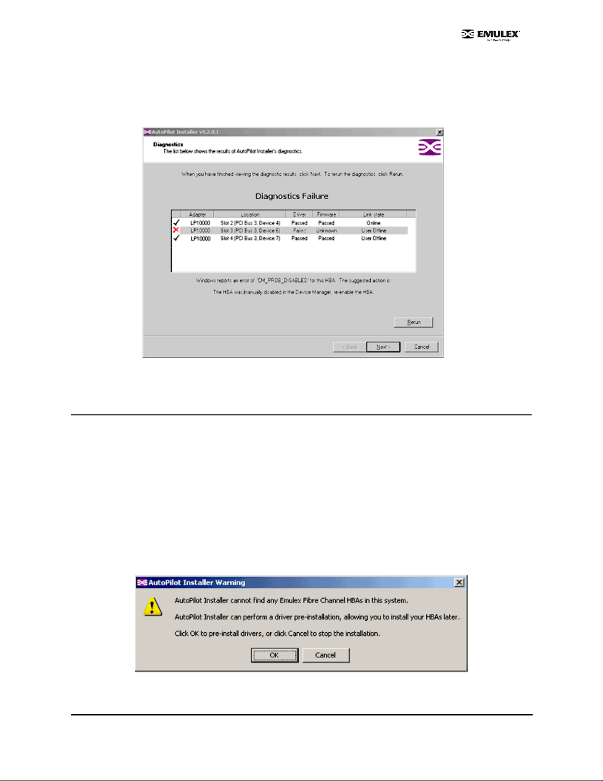
If the Installation Fails
If the installation fails, the Diagnostics window is displayed. To view the reason an HBA failed,
select the HBA row. The reason and suggested corrective action are displayed below the list.
Figure 1: Diagnostics Window
Perform the suggested corrective action and run APInstaller.exe again.
Software-First Installation
Prerequisites
• Distribution executable file downloaded from the Emulex Web site.
Procedure
To perform a software-first installation:
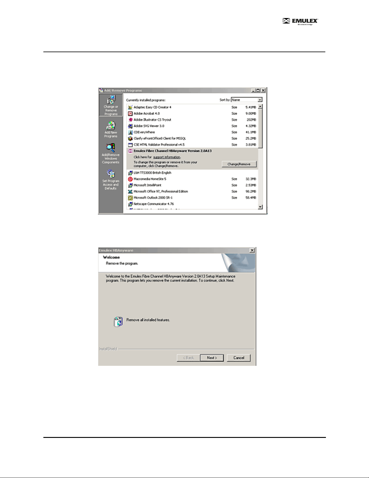
1. If you have already extracted the driver and utility files, run the APInstaller.exe file.
If you have not extracted the driver and utility files, run the distribution executable file (page 5),
and leave the Start AutoPilot Installer checkbox selected. Click Finish.
The following message is displayed:
Figure 2: Message (Software-First Installation)
SCSIport Miniport Driver Installation Section Page 8
Page 15

2. Click OK.
3. The Welcome window is displayed.
4. Click Next. Installation automatically completes.
5. View the progress of the installation. Once the installation is successful, a congratulations
window is displayed.
6. View or print a report, if desired.
View Installation Report - your text editor (typically Notepad) displays a report with task results.
The text file is named in the following format: report_MM-DD-YY-#.txt
• MM = month
• DD = day
• YY = year
• # = report number
Print Installation Report - your default print window is displayed.
7. Click Finish to close AutoPilot Installer. If the system requires a reboot for this change to take
effect, you are prompted to do so when you click Finish.
SCSIport Miniport Driver Installation Section Page 9
Page 16

HBAnyware Security Configurator Installation
After the HBAnyware utility and remote server are installed on a group of systems, HBAnyware can
remotely access and manage the HBAs on any systems in the group. This may not be desirable
because any system with remote access can perform actions such as resetting boards or downloading
firmware.
The HBAnyware Security Configurator controls which HBAnyware systems can remotely access and
manage HBAs on other systems in an FC network. HBAnyware security is system-based, not userbased. As a result, anyone with access to a system that has been granted HBAnyware client access to
remote HBAs can manage those HBAs.
Prerequisites
• SCSIport Miniport driver is installed.
• HBAnyware and lputilnt are installed.
Procedure
To install the HBAnyware Security Configurator:
1. Locate the SSCsetup.exe file. The default path for this file is:
C:\Program Files\HBAnyware
2. Double-click the SSCsetup.exe file. A welcome window is displayed. Click Next.
3. The Setup Status window is displayed. After setup is completed, the Emulex HBAnyware
Security Setup Completed window is displayed.
4. Click Finish.
Unattended Installation
Unattended installation is invoked from the command line. The apinstall command uses installation and
driver settings that are stored in a configuration file (APInstall.cfg). The default APInstall.cfg file is in the
AutoPilot Installer folder located in the Emulex folder in the Program Files directory.
Make a copy of the APInstall.cfg file before you make modifications. The APInstall.cfg file should be
used as a starting point for scripting an unattended installation.
The APInstall.cfg file must be modified to enable silent mode, specify a driver location and specify
allowable driver types. The Installation report name and location may be chang ed from the default, an d
optional parameters may be enabled.
Prerequisites
• Distribution executable file is downloaded from the Emulex Web site.
• It is highly recommended that you make a copy of the APInstall.cfg file and rename it for your
customization.
SCSIport Miniport Driver Installation Section Page 10
Page 17

AutoPilot Configuration File Format
The APInstall.cfg file is organized into commented sections, grouped according to related commands.
• Lines that begin with a semicolon are comments. Enable sample comment lines by removing the
semicolon.
• There are four main sections. Two are required and two are optional. Driver parameters must be
set up in the [SCSIPORT.PARAMS] section. Each section begins with a heading.
• [AUTOPILOT.CONFIG] - this required section contains settings that control and configure
the AutoPilot Installer’s operation.
• [SCSIPORT.CONFIGURATION] - this optional section may contain questions that must
answered during the installation process. This section is applicable to attended in stallations
only.
• [SCSIPORT.PARAMS] - this required section can specify driver parameters. Parameters are
read exactly as they are entered and are written to the registry.
• [SYSTEM.PARAMS] - this section may be created to specify system parameters.
Mandatory Configuration File Changes
Locate the Mandatory Configuration File Changes heading in the [AUTOPILOT.CONFIG] section of the
APInstall.cfg file.
Enable Silent Mode
Silent mode must be enabled to run an unattended installation. Enable silent mode by removing the
semicolon before:
;SilentInstallEnable = "TRUE"
Set Up Allowable Driver Types
Four configuration file settings determine what driver types the AutoPilot Installer is allowed to install.
Remove the semicolon before:
;win2000DriverPreference = "SCSIPORT"
;win2003DriverPreference = "SCSIPORT"
;win2000AllowableDrivers = "SCSIPORT"
;win2003AllowableDrivers = "SCSIPORT"
Note: All four of these settings must specify the same driver type.
Set Up Driver Location
When in silent mode, the location of the AutoPilot Installer must be specified. Locate the following line in
the APInstall.cfg file:
;LocalDriverLocation = "C:\autopilot\SCSIPortDriver\Package"
Remove the semicolon before this line and modify this path to reflect the location of the driver. The driver
location can be a local disk or a network shared drive.
SCSIport Miniport Driver Installation Section Page 11
Page 18

Delete Questions in the APInstall.cfg File
Locate the [SCSIPORT.CONFIGURATION] section in the APInstall.cfg file.
The [SCSIPORT.CONFIGURATION] section may contain a [QUESTIONS] section with vendor-specific
installation questions. The entire [SCSIPORT.CONFIGURATION] section must be removed or
commented for a silent installation.
Optional Configuration File Changes
Locate the Optional Configuration File Changes heading in the [AUTOPILOT.CONFIG] section of the
APInstall.cfg file. This heading follows Mandatory Configuration File Changes.
Change Utility Installation Location
AutoPilot Installer normally installs utilities from a Utilities subdirectory located in the same directory as
AutoPilot Installer.
To modify the location, locate the following line in the APInstall.cfg file:
;UtilitiesLocation = "C:\Autopilot\ScsiportDriver\Utilities"
Modify this directory path to specify an alternate location, such as a network shared drive.
Set Up an Automatic System Restart During an Unattended Installation
AutoPilot Installer does not automatically perform system restarts for the following reasons:
• Restarts often require a login as part of Windows start-up process. If the system is rest arted, the
installation process stops until a login is performed.
• AutoPilot Installer does not know if it is safe to restart the system. Restarts while applications are
active can result in the loss of data.
To configure Windows to start up without requiring a login, rem ove the semicolon from th is line:
;SilentRebootEnable = "FALSE"
Change this parameter to true:
SilentRebootEnable = "TRUE"
Set Up Installation Report Title and Location
You can change the Installation report name and the location to which it is written. This information must
be specified in one command. In the following example s is the system drive. Remove the semicolon
before:
;s\Program Files\Emulex\AutoPilot Installer\reports\report_mm-dd-yy.txt
Default File Name
This default file name is ”report_mm-dd-yy.txt” and uses the following format to generate the name of
this .txt file:
report_mm-dd-yy.txt
where ‘mm’ is the month, ‘dd’ is the date, and ‘yy’ is the year.
SCSIport Miniport Driver Installation Section Page 12
Page 19

Default Report Location
By default, the report is written to the system driver. In the following example s is the system drive. Your
system driver may be different.
"s:\Program Files\Emulex\AutoPilot Installer\reports\report_mm-dd-yy.txt"
Note: Both the report location and file name must be specified.
Set Up Existing Driver Parameters Retention or Override
The ForceRegUpdate driver parameter setting determines if existing driver parameters are retained or
changed when updating the driver. Setting the ForceRegUpdate parameter to True causes all existing
driver parameters to be removed from the registry and replaced with the parameters specified in the
APInstall.cfg file. Setting the ForceRegUpdate parameter to False causes all existing driver parameters
to be retained, ignoring any parameter settings in the APInstall.cfg file. The ForceRegUpdate parameter
does not affect any existing persistent bindings.
The following example will retain existing driver parameters:
ForceRegUpdate = "FALSE"
Note: This setting can be also used for attended installations with the AutoPilot
Installer wizard by modifying the APInstall.cfg file in the AutoPilot Installer folder.
Set Up Re-Installation of an Existing Driver Version
By default, AutoPilot Installer will only do update a driver if the new driver version is different than the
installed driver version. If necessary, the ForceDriverUpdate setting can be used to re-install the same
driver version. To force a re-installation of the same driver type and version, remove the semicolon from
this line:
; ForceDriverUpdate = "FALSE"
Change this parameter to true:
ForceDriverUpdate = "TRUE"
Note: This setting can only be used for unattended installations.
Set Up a Driver Type to be Forced
By default the ForceDriverTypeChange parameter is set to ‘FALSE’. When set to the default, AutoPilot
Installer will install drivers on HBAs that have no other driver installed, or whose current driver type
matches that of the driver being installed.
If this parameter is changed to ‘TRUE’, AutoPilot Installer will cause silent installations to update or
install the current driver on each HBA in the system, without any regard to driver type. For example, you
would want this option to be left on or set to “TRUE’ to silently install the Storport Miniport driver on any
HBAs that are currently running SCSIport Miniport or FC Port drivers.
Remove the semicolon from this line:
;ForceDriverTypeChange = "FALSE"
To change this parameter to true:
ForceDriverTypeChange = "TRUE"
SCSIport Miniport Driver Installation Section Page 13
Page 20

Set Up Driver Parameters
The SCSIport Miniport driver parameter defaults may be changed by modifying this section of the
APInstall.cfg file. Locate the [SCSIPORT.PARAMS] section in the APInstall.cfg file. This mandatory
section follows Optional Configuration File Changes. Under the [SCSIPORT.PARAMS] heading, list the
parameters and new values for the driver to use.
For example: LinkTimeout = 45
See the Configuration section for a listing of driver parameters and their defaults and valid values.
Set Up System Parameters
To change the system parameters, create a [SYSTEM.PARAMS] section in the APInstall.cfg file. Create
this section in the Optional Configuration File Changes heading in the [AUTOPILOT.CONFIG] section of
the APInstall.cfg file.
Error Codes
AutoPilot Installer sets an exit code to indicate whether an installation was successful or an error
occurred. These error codes allow AutoPilot Installer to be used in scripts with error handling. AutoPilot
Installer’s silent mode specifically returns the following values:
Table 3: Unattended Installation Error Codes
Error Code Hex Description
0
2
87
110
1248
2001
0x00000000
0x00000002
0x00000087
0x0000006E
0x000004E0
0x000007D1
2399141889 0x8F000001
No errors.
No appropriate driver found.
Invalid configuration file parameters.
Could not open installation report file.
No HBA found.
Driver found is the same type as the existing driver and has the same, or
older, version number.
Unsupported operating system detected.
2399141890 0x8F000002 AutoPilot could not locate the configuration file.
2399141891 0x8F000003 One or more HBAs is disabled.
2399141892 0x8F000004 The selected driver is 64-bit and this system is 32-bit.
2399141893 0x8F000005 The selected driver is 32-bit and this system is 64-bit.
2399141894 0x8F000006 Other hardware installation activity is pending.
2399141895 0x8F000007 The user does not wish to perform a 'software-first' install.
2399141896 0x8F000008
Silent installation did not find any appropriate drivers.
2399141897 0x8F000009 A Silent reboot was attempted, but returned an error code instead.
SCSIport Miniport Driver Installation Section Page 14
Page 21

Invoke AutoPilot Installer
If the configuration file has been modified and saved with its original name (APInstall.cfg), at the
command line, type:
apinstall
If the configuration file has been modified and saved with a different name and/or the configuration file
location has changed, you must specify the entire path location (using the standard drive:\directory
path\filename format) and the entire name of the configuration file. In the following example, the
configuration file has been renamed and relocated:
Example:
ApInstall g:\autopilot\mysetup\cs_apinstall.cfg
Batch File Example
Modifying the configuration file enables you to script the installation of a system's driver. The following
example batch file assumes that you have made mandatory changes to the APInstall.cfg file (page 11),
as well as any optional changes (page 12).
If your systems have been set up with a service supporting remote execution, then you can create a
batch file to remotely update drivers for all of the systems on the storage net. If Microsoft's RCMD
service was installed, a batch file similar to the following could also be used for remote execution.
rcmd \\server1 g:\autopilot\ApInstall g:\autopilot\mysetup\apinstall.cfg
if errorlevel 1 goto server1ok
echo AutoPilot reported an error upgrading Server 1.
if not errorlevel 2147483650 goto unsupported
echo Configuration file missing.
goto server1ok
:unsupported
if not errorlevel 2147483649 goto older
echo Unsupported operating system detected.
:older
if not errorlevel 2001 goto none
echo The driver found is the same or older than the existing driver.
goto server1ok
:none
if not errorlevel 1248 goto noreport
echo No HBA found.
goto server1ok
:noreport
if not errorlevel 110 goto nocfg
echo Could not open installation report file.
goto server1ok
:nocfg
if not errorlevel 87 goto badcfg
echo Invalid configuration file parameters.
goto server1ok
:badcfg
if not errorlevel 2 goto server1ok
echo No appropriate driver found.
server1ok
SCSIport Miniport Driver Installation Section Page 15
Page 22

rcmd \\server2 g:\autopilot\ApInstall g:\autopilot\mysetup\apinstall.cfg
if errorlevel 1 goto server2ok
echo AutoPilot reported an error upgrading Server 2.
if not errorlevel 2147483650 goto unsupported
echo Configuration file missing.
goto server2ok
:unsupported
if not errorlevel 2147483649 goto older
echo Unsupported operating system detected.
:older2
if not errorlevel 2001 goto none2
echo The driver found is the same or older than the existing driver.
goto server2ok
:none2
if not errorlevel 1248 goto noreport2
echo No HBA found.
goto server2ok
:noreport
if not errorlevel 110 goto nocfg2
echo Could not open installation report file.
goto server2ok
:nocfg2
if not errorlevel 87 goto badcfg2
echo Invalid configuration file parameters.
goto server2ok
:badcfg2
if not errorlevel 2 goto server2ok
echo No appropriate driver found.
server2ok
SCSIport Miniport Driver Installation Section Page 16
Page 23

Manual Installation
Overview
If desired, the SCSIport Miniport driver and utilities can be installed manually without using AutoPilot
Installer. This is accomplished by following the same steps used before AutoPilot Installer was available.
The driver was extracted when you ran the Distribution Executable File and includes a file for the driver
and files for the driver utilities (lputilnt, HBAnyware and HBA API files). Perform the following steps:
1. Manually install the SCSIport Miniport driver.
2. If you are updating an earlier version of the driver, reboot the computer.
3. Manually install the driver utilities.
Caution: If you manually install the driver utilities before manually installing the
SCSIport Miniport driver and attempt to run HBAnyware, an operating system
error may occur (often referred to as a “blue screen”). The computer may
freeze and require restarting to make the computer operational.
Manually Install the SCSIport Miniport Driver
Prerequisites
• Downloaded and extracted contents of the Distribution Executable.
Procedure
To update the SCSIport Miniport driver from the d esktop:
1. Select Start, Control Panel and System.
2. Select the Hardware tab.
3. Click Device Manager.
4. Open the "SCSI and RAID Controllers" item.
5. Double-click the desired Emulex HBA.
Note: The driver will affect only the selected HBA. If there are other HBAs in the system,
you will need to repeat this process for each HBA. All DC models will be displayed
in Device Manager as two HBAs, therefore each HBA must be updated.
6. Select the Driver tab. Click Update Driver. The Update Driver wizard starts.
7. Select "Install from a list or specific location (Advanced)". Click Next.
8. Select "Don't search. I will choose the driver to install". Click Next.
9. Click Have Disk. Direct the Device Wizard to the location of OEMSETUP.INF. If you have
downloaded the SCSIport files to the default directory, the path will be:
• C\Progra m Files\Emulex\AutoPilot Installer\Drivers\SCSIport\x86 fo r the 32-bit driver
version
or
• C\Progra m Files\Emulex\AutoPilot Installer\Drivers\SCSIport\x64 fo r the x64 driver versio n
or
• C\Program Files\Emulex\AutoPilot Installer\Drivers\SCSIport\IA64 for the Itanium 64-bit
driver version.
SCSIport Miniport Driver Installation Section Page 17
Page 24

10. Click OK.
11. Select "Emulex LPX000 Fibre Channel SCSIport Driver" (your HBA model will be displayed
here).
12. Click Next.
13. Click Finish.
The driver installation is complete. The driver should start up automatically. If the HBA is con-
nected to a Fibre Channel switch, hub or data storage device, a blinking yellow light on the back
of the HBA will indicate a link up condition.
To verify that the driver is present and active:
1. Click Driver Details in the Emulex LPXXXXX Fibre Channel SCSIport Miniport Driver window.
2. Select
information.
lpxftr.sys to display the driver's provider, file version, copyright and digital signer
Install the Driver Utilities
The utility installation installs lputilnt, HBAnyware and the HBA API files.
Prerequisites
• SCSIport Miniport driver is installed.
• Extracted setupapps.exe (extracted when you ran the Distribution Executable file). If you have
downloaded the SCSIport Miniport files to the default directory, the path will be: C\\Program
Files\Emulex\AutoPilot Installer\Utilities\.
Procedure
To install the utility:
1. Run setupapps.exe.
2. Follow the instructions on the setup windows.
3. Click Finish in the last dialog box to exit Setup. The utility installation is complete.The
HBAnyware utility automatically starts running.
SCSIport Miniport Driver Installation Section Page 18
Page 25
Uninstall the Utility Package
To uninstall the HBAnyware utility package:
1. Click Start, Settings, and Control Panel. The Add/Re move Programs window is displayed.
Select the Install/Uninstall tab. A window similar to Figure 3 will be displayed.
Figure 3: Add Remove Programs Windo w
2. Select the Emulex Fibre Channel item and click Change/Remove. A window similar to Figure 4
will be displayed.
Figure 4: Emulex HBAnyware Welcome Window
SCSIport Miniport Driver Installation Section Page 19
Page 26

3. Click Next. The utilities are removed from the system.
Figure 5: Emulex HBAnyware Completion Window
4. Click Finish. Uninstallation is complete.
Uninstall the Driver
To uninstall the driver:
1. From the Windows desktop, click Start and Control Panel.
2. Double-click the System item. The System Properties dialog box is displayed. Click the
Hardware tab.
Figure 6: System Properties Window
SCSIport Miniport Driver Installation Section Page 20
Page 27

3. Click Device Manager. Device Manager is displayed. Double-click SCSI and RAID controllers.
Figure 7: Device Manage
4. Double-click the HBA from which you want to remove the driver. A device-specific dialog box is
displayed. Click the Driver tab.
5. Click Uninstall.
6. Click OK to Uninstall.
The driver is uninstalled.Install the Emulex Simulate Device
Installing the Emulex Simulate Device creates a dummy disk to force the driver to load if no disk devices
are present at boot time. The Emulex Simulate Device is enabled by setting the SimulateDevice
parameter to 1 (it is disabled by default). You can enable this setting using the lputilnt.
Note: Microsoft provides simulate device (CreateInitiatorLU) functionality on Windows
Server 2003 and it is enabled by default during installation of the Emulex SCSIport
Miniport driver. If you have a Windows Server 2003 system, use the simulate device
provided by Microsoft.
1. Restart the computer. A window displays "Found New Hardware Wizard". Click Next.
2. Select "Display a list of known drivers for this device so that I can choose a specific driver", and
click Next.
3. Select "System Devices" and click Next.
4. Select "Emulex" in the Manufacturers window. Select "Emulex Simulate Device" in the Models
window. Click Next.
5. Follow the instructions to finish installing this device.
SCSIport Miniport Driver Installation Section Page 21
Page 28

Configuration
Introduction
The Emulex® SCSIport Miniport driver has many options that you can modify to provide for different
behavior. You can change these options in one of two ways:
• The HBAnyware™ utility (HBAnyware) allows you to set driver parameters on remote and local
host bus adapters (HBAs). Use HBAnyware to do any of these tasks:
• Discover HBAs
• Reset HBAs
•Sort HBAs
• Set up p ersistent bindin g
• Set topo logy option s
• Set driver parameters
• Update firmware on the local HBA or on remote HBAs
• Upda te x86 BootBIO S
• Enable th e BootBIOS message
• Upda te EFIBoot (64-b it only)
Note: HBAnyware must be running on all remote hosts that are to be discovered and
managed.
Remote capabilities of HBAnyware are subjec t to fabric zoning configuration. Remote
hosts to be discovered and managed by HBAnyware must be in the same zone.
• The LightPulse™ utility (lputilnt) allows you to set driver parameters on local HBAs only. Use the
lputilnt to do any of these tasks:
• Downloa d Peripheral Co mponen t Intercon nect (PCI) config uration data files
• Assign an Arbitrated Loop Physical Ad dress (AL_PA)
• Perform global a nd target mapping an d maskin g
• Globally auto map all logical un it numbe rs (LUNs)
• Globally unm ask all LUNs
• Set up p ersistent bindin g
• Hot swap a device
• Set topo logy option s
• Map device iden tifiers (IDs)
• Break SCSI reser vations
• Set driver parameters
• Update firmware on the local HBA
• Upda te x86 BootBIO S
• Enable th e BootBIOS message
SCSIport Miniport Driver Configuration Section Page 22
Page 29

Start HBAnyware
Start HBAnyware in Remote Manager Mode
After the HBAnyware server has been installed as an NT service, you can access this utility from the
desktop Start menu. On your desktop :
• Click Start, Programs and HBAnyware. HBAnyware is displayed.
Figure 8: HBAnyware Utility Window, General Tab
Note: Illustrations in this document are examples; model and version numbers on your
screens will reflect your system’s configuration.
The HBAnyware Utility window contains five basic elements: the menu bar, the toolbar, the discovery
tree, the property tabs and the status bar.
Note: The element that you select in the discovery tree determines whether a menu item or
toolbar icon is active. For example, if you select the local host or other system host,
the Reset Adapter item on the Adapter menu becomes unavailable. The Reset
Adapter toolbar button becomes unavailable as well.
SCSIport Miniport Driver Configuration Section Page 23
Page 30

Start HBAnyware in Local Element Manager Mode
HBAnyware can also launch with a command line call for both Windows and UNIX systems.
To launch HBAnyware from the comm and line:
1. Type “HBAnyware” and press <ENTER>. This starts HBAnyware running in-band access. You
can also start the utility running in out-of-band access by adding an argument in the form
“h=<host>”. The <host> argument may be either the internet protocol (IP) address of the host or
its system name. The call will use a default IP port of 23333, but you can override this by
optionally appending a colon (:) and the IP port.
Note: Remember that not all HBAs for a specific host can be run in-band. Therefore,
running out-of-band for that host may display HBAs that do not appear on that host
when running in-band.
Examples of Modifications
• HBAnyware h=138.239.82.2
HBAnyware will show HBAs in the host with the IP address 138.239.82.2.
• HBAnyware h=Util01
HBAnyware will show HBAs in the host named Util01.
• HBAnyware h=138.239.82.2:4295
HBAnyware will show HBAs in the host with the IP address 138.239.82.2 using IP Port 4295.
• HBAnyware h=Util01:4295
HBAnyware will show HBAs in the host named Util01 using IP port 4295.
Run this modified command line to launch HBAnyware for a single, rem ote host in loca l mode .
SCSIport Miniport Driver Configuration Section Page 24
Page 31

HBAnyware Window Element Definitions
Figure 9: HBAnyware Window with Element C all Ou ts
The Menu Bar
The menu bar contains command menus that enable you to perform a variety of tasks such as exiting
HBAnyware, resetting HBAs and sorting items in the discovery tree view. Many of the menu bar
commands are also available from the toolbar.
The Toolbar
The toolbar contains buttons that enable you to refresh the discovery tree view, reset the selected HBA
and sort the discovery tree view. The toolbar is visible by default. Use the Toolbar item in the View
menu to hide the toolbar. If the item is checked, the toolbar is visible.
Toolbar Icon Definitions
Click the Rediscover button to refresh the discovery tree display.
Click the Reset button to reset the selected HBA.
SCSIport Miniport Driver Configuration Section Page 25
Page 32

Sort and Display Icons
You can so rt discovered HBAs can be sor ted by host nam e or fabric add resses.You can also choose to
display only local or remote HBAs. See page 32 for details on sorting icons.
Group HBAs by host name (default)
Group HBAs by fabric address
Local HBAs only
Online help
Discovery Tree
The discovery tree (left pane) shows icons that represent discovered network storage area network
(SAN) elements (local host name, system host names and all HBAs active on each host). Targets and
LUNs, when present, are also displayed.
Figure 10: HBAnyware Discovery Tree
Discovery Tree Icons
Discovery tree icons represent the following:
The local host.
Other hosts connected to the system.
SCSIport Miniport Driver Configuration Section Page 26
Page 33

A green HBA icon with black descriptive text represents an online HBA.
A gray HBA icon with red descriptive text represents an offline HBA or an HBA that is otherwise
inaccessible. Several situations could cause the HBA to be offline or inaccessible:
• The HBA on a local host is not connected to the network but is still available for local access.
• The HBA on a local host has malfunctioned and is inaccessible to the local host as well as to
the network.
• The HBA o n a local host is busy p erforming a loca l download and therefo re tempora rily
inaccessible to the local host as well as to the network.
The Target icon represents connections to individual storage d evices.
The LUN icon represents connections to individual LUNs.
Property Tabs
The property tabs display configuration, statistical and status information for network elements. The set
of available tabs is context-sensitive, depending on the type of network element or HBA currently
selected in the discovery tree.
Status B a r
As you navigate through the menu bar or the toolbar, help messages appear on the status bar near the
bottom of the HBAnyware window.
The status bar is visible by default. Use the Status Bar item in the View menu to hide the status bar. If
the item is checked, the status bar is visible.
Use HBAnyware Command-Line Interface
The CLI (command-line interface) Client component of HBAnyware provides access to the capabilities of
the Remote Management library from a console command prompt. This component is inte nded for use
in scripted operations from within shell scripts, batch files, or the specific platform equivalent.
HbaCmd can be run in out-of-band mode by making the first argument 'h=<host>'. For exam ple:
c:\>hbacmd h=cp-hp5670 listhbas
c:\>hbacmd h=138.239.91.121 listhbas
The CLI Client
The CLI Client is a console application named HBACMD.EXE. Each time you run this application from
the command line, a single operation is performed.
The first parameter of this command is the requested operation. When the specified op eration is
completed, the command prompt is displayed. Most operations retrie ve information ab out an entity on
the SAN and show that information on the console.
Most of the CLI Client commands require one or more additional parameters that specify the nature of
the command. A parameter used by many HBACMD commands specifies the World Wide Port Name
(WWPN) of the HBA target of the command. For example, the following command displays the po rt
attributes for the HBA with the specified WWPN:
c:\>hbacmd portattrib 10:00:00:00:c9:20:20:20
SCSIport Miniport Driver Configuration Section Page 27
Page 34

CLI Client Command Reference
Version
Syntax: HBACMD VERSION
Description: The current version of the HBAnyware CLI Client application.
Parameters: N/A
List HBAs
Syntax: HBACMD LISTHBAS
Description: A list of the discovered manageable Emulex HBAs and their World Wide Node Name (Wanness.
Parameters: N/A
Display HBA Attributes
Syntax: HBACMD HBAAttrib <wwpn>
Description: A list of attributes for the HBA with the specified World Wide Port Name (WWPN).
Parameters: wwpn The WWPN of the HBA. The HBA can be either local or remote.
Port Attributes
Syntax: HBACMD PortAttrib <wwpn>
Description: A list of attributes for the port with the specified WWPN.
Parameters: wwpn The WWPN of the port. This port can be either local or remote.
Port Statistics
Syntax: HBACMD PortStat <wwpn>
Description: A list of statistics for the port with the specified WWPN.
Parameters: wwpn The WWPN of the port. The port can be either local or remote.
Server Attributes
Syntax: HBACMD ServerAttrib <wwpn>
Description: A list of attributes for the specified server.
Parameters: wwpn The WWPN of the port. The port can be either local or remote.
Download
Syntax: HBACMD DOWNLOAD <wwpn> <filename>
Description: Loads the specified firmware image to the (HBA) with the specified WWPN.
Parameters: wwpn The WWPN of the HBA that is the target of the firmware download.
The HBA can be either local or remote.
Filename: The pathname of the firmware image that is to be loaded. This can be any file that
is accessible to the CLI client application, but we recommend that you keep image files in
the Emulex Repository folder or directory.
Reset Adapter
Syntax: HBACMD RESET <wwpn>
Description: Resets the HBA with the specified WWPN.
Parameters: wwpn The WWPN of the port. The port can be either local or remote.
Target Mapping
Syntax: HBACMD TargetMapping <wwpn>
Description: List of mapped targets for the port with the specified WWPN.
Parameters: wwpn The WWPN of the port. The port can be either local or remote.
SCSIport Miniport Driver Configuration Section Page 28
Page 35
Start the LightPulse Utility (lputilnt)
To start lputilnt, do one of the following:
• Click Start, Programs, Emulex and lputilnt.
• Browse to lputilnt.exe and run this command.
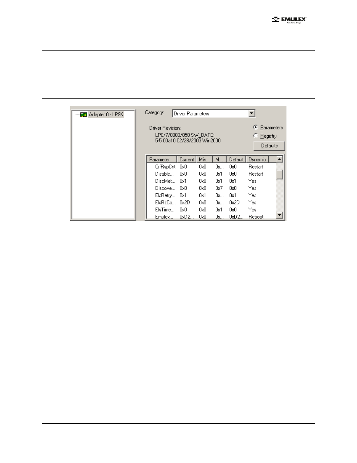
lputilnt Category Summaries
Figure 11: lputilnt Driver ParametersView
Eight categories are available:
• Adapter Revision Levels - View information about the chipset and firmware revision levels of
the selected HBA.
• Firmware Maintenance - View details about the firmware in the flash read-only memory (ROM)
of the selected HBA. Update HBA firmware and boot code, manage existing firmware and
enable or disable the BootBIOS bootup message.
• Loop Map - View a list of the members of the selected HBA.
• PCI Registers - View the values of the PCI configuration registers for the selected HBA.
• Configuration Data - View information about the data in each of the configuration regions in the
flash ROM of the selected HBA. Download PCI configuration files (CFL).
• Driver Parameters - View and change device driver parameters.
• Persistent Binding - View and manage persistent binding for the HBA, and LUN mapping and
masking for devices in your SAN.
• Link Statistics - View statistics about the arbitrated loop of the selected HBA.
• Status and Counters - View status and counters for bytes, frames, sequences, exchanges, and
so on.
SCSIport Miniport Driver Configuration Section Page 29
Page 36

HBA Tasks
Discover HBAs
Discover HBAs using either HBAnyware or lputilnt.
• HBAnyware allows you to discover both local and remote HBAs.
• lputilnt allows you to discover local HBAs only.
Discover HBAs Using HBAnyware
Local and remote HBAs are discovered automatically when you launch HBAnyware. Initially, both local
and remote HBAs are displayed.
Note: HBAnyware must be running on all remote hosts that are to be discovered and
managed. Remote capabilities of HBAnyware are subject to fabric zoning
configuration. Remote hosts to be discovered and managed by HBAnyware must be
in the same zone.
Figure 12: HBAnyware, Discovered Elements Tab
SCSIport Miniport Driver Configuration Section Page 30
Page 37

Discover HBAs Using lputilnt
Local HBAs are discovered automatically when you launch lputilnt.
Figure 13: lputilnt HBA Information
Reset the HBA
Reset the HBA Using HBAnyware
To reset a local or remote HBA:
1. Start HBAnyware.
2. In the directory tree, click the HBA you want to reset.
3. Do one of the following:
• From the menu bar, click Adapter, and then Reset Adapter.
• Click the Reset Toolbar button.
The reset may require several seconds to complete. While the HBA is resetting, “Reset in progress” is
displayed in the status bar. “Ready” is displayed in the status bar when reset has finished.
Reset the HBA Using lputilnt
To reset the local HBA:
1. Start lputint.
2. In the left pane, click the HBA you want to reset.
3. Do one of the following:
• From the menu bar:
Click Adapter, and then click Reset Adapter.
or
• From the toolbar:
Click the Reset Adapter button.
SCSIport Miniport Driver Configuration Section Page 31
Page 38

Download PCI Configuration Files Using lputilnt
lputilnt provides information about the data in each of the configuration regions in the flas h read-on ly
memory (ROM) of the selected HBA. Select a region in the drop-down Region list, and the data
contained in that region is displayed. Regions 5, 6 and 7 allow you to download PCI configuration data
files to the selected region to change the PCI configuration (PCI device ID).
Note: Downloading PCI configuration files is not applicable to the following Emulex HBAs: LP982, LP952L and
LP850.
Caution: Download PCI configuration files only with the assistance of Emulex technical support.
Sort HBA Information
Sort HBAs Using HBAnyware
Use HBAnyware to sort the way discovered HBAs are displayed. Sort HBAs by host name, fabric name,
HBA name, target name and LUN name. By default, both local and remote HBAs are displayed by host
name/fabric name.
• Switch between host name or fabric ID in one of two ways:
• From the menu bar :
Click View, then Sort by Host Name, Sor t by Fabric ID . The current HBA display mode
is checked.
or
• From the toolbar:
Sort by host name (default).
or
Sort by fabric ID.
• HBAnyware sorts in ascending order. The sort recognizes letters, numbers, spaces and
punctuation marks.
Sort By Host Name
• Initially sorts by host name. Host names cannot be changed using HBAnyware; names must be
changed locally.
• Within each host system, sorts by HBA model.
• If multiple HBAs have the same model number, sorts models by WWNN.
• If targets are present, sorts by WWPN. Multiple HBAs may refer to the same target.
• If LUNs are present, sorts by LUN name.
Sort by Fabric Address
• Initially sorts by fabric ID.
• Within each fabric ID, sorts by HBA model.
• If multiple HBAs have the same model number, sorts models by WWNN.
• If targets are present, sorts by WWPN. Multiple HBAs may refer to the same target.
• If LUNs are present, sorts by LUN name.
SCSIport Miniport Driver Configuration Section Page 32
Page 39

• If the fabric ID is all zeros, no fabric attachment is present.
Sort Local HBAs Only Using HBAnyware
Shows the local HBA name or fabric address.
• To view local HBAs only:
• From the menu bar :
Click View, then Local HBAs Only. Th e current HBA d isplay mode is checked.
or
• From the toolbar:
Click .
Sort Local HBAs Using lputilnt
Local HBAs are automatically displayed in the left pane of the main window.
View HBA Information Using HBAnyware
View Discovered Elements
This tab contains a general summary of the discovered elements. The Discovered Elements node is
the root of the discovery tree, but it does not represent a specific network element. Expanding it will
reveal all hosts, LUNs, targets and HBAs that are visible on the SAN.
To view the discovered elements, click Discovered Elements in the discovery tree.
Figure 14: HBAnyware, Discovered Elements Tab
Field Definitions
• Number of Fabrics - the total number of fabrics discovered ("Unavailable" if Sort by Host is
active).
• Number of Hosts - the total number of host computers discovered. This includes servers,
workstations, personal computers, multiprocessors and clustered computer complexes
("Unavailable" if Sort by Fabric is active).
• Number of Adapters - the total number of HBAs discovered.
• Number of Targets - the total number of unique targets discovered on the SAN. In the discovery
tree, the same target can appear under more than one HBA.
SCSIport Miniport Driver Configuration Section Page 33
Page 40

View Host Attributes
The Host Attributes tab contains information specific to the selected host.
1. To view the host attributes:
• From the menu bar :
Click View, then Sort by Host Name.
or
• From the toolbar:
Click the button.
2. Click a host name in the discovery tree.
Figure 15: HBAnyware, Host Attributes Tab
General Area Field Definitions
• Name - the name of the host.
• HBAnyware Server Version - the version of the HBAnyware server that is running on that host. If
different versions of HBAnyware are installed on different hosts in the SAN, those differences
appear in this field.
Resource Location Field Definitions
• Firmware - the directory path where the firmware image files are moved prior to being
downloaded to the HBAs on that host.
View Target Attributes
The Target Attributes tab contains information specific to the selected target.
1. To view target attributes:
• From the menu bar :
Click View, then Sort by Host Name.
or
• From the toolbar:
Click the button.
SCSIport Miniport Driver Configuration Section Page 34
Page 41

2. Click a target in the discovery tree.
Figure 16: HBAnyware, Target Attributes Tab
Target Attributes Field Definitions
• Vendor/Product Information
• FC ID - the Fibre Channel (FC) ID for the target; assigned automatically in the firmware.
• SCSI Bus Nu mber - defines the SCSI b us to which the target is mapped.
• SCSI Target Number - the target's identifier on the SCSI bus.
• Node WWN - the uniq ue 64-bit num ber, in hexadecimal, for the target (N_PORT or
NL_PORT).
• Port WWN - the u nique 64-bit numbe r, in hexadecimal, for the fabric (F_PORT or
FL_PORT).
• OS Device Name - operating system device name.
View LUN Attributes
The LUN Attributes tab contains information specific to the selected logical unit number (LUN).
1. To view the LUN attributes:
• From the menu bar :
Click View, then Sort by Host Name.
or
• From the toolbar:
Click the button.
SCSIport Miniport Driver Configuration Section Page 35
Page 42

2. Click a LUN in the discovery tree.
Figure 17: HBAnyware, LUN Attributes Tab
LUN Attributes Field Definitions
• Vendor Product Information
• Vendor ID - the name of the vendor of the logical unit.
• Produ ct ID - the ven dor-specific ID for the logical unit.
• Revisio n - the vendo r-specific revision num ber for the logical unit.
• Mapping Information
• FCP LUN - the FC Protocol identifier used by the HBA to map to the SCSI OS LUN.
• SCSI O S LUN - SCSI identifier used by the ope rating system to ma p to a specific LUN.
• LUN Capacity
• Capacity - the capacity of the logical unit, in megabyte s.
• Blo ck Leng th - the length of a logical u nit block in bytes.
View Fabric Attributes
The Fabric Attributes tab contains information specific to the selected fabric.
Figure 18: HBAnyware, Fabrics Attributes Tab
SCSIport Miniport Driver Configuration Section Page 36
Page 43

1. To view the fabric attribu tes:
• From the menu bar :
Click View, then Sort by Fabric ID.
or
• From the toolbar:
Click the button.
2. Click on a fabric address in the discovery tree.
General Area Field Definitions
• Name - a 64-bit unique identifier assigned to each FC fabric.
View General HBA Attributes
The General tab contains general attributes associated with the selected HBA.
Figure 19: HBAnyware, General Tab
Adapter Summary Field Definitions
Model - the Emulex HBA model number.
Description - a formal description of the HBA, including model number, bus type and link speed. This
field is recessed, indicating that the information in this field m ay exceed the visible length of the field.
Use the arrow keys on your keyboard to scroll and view additional information.
Node WWN - a 64-bit worldwide unique identifier assigned to the node.
Driver Version - the driver version number and the HBA application programming interface (HBA API)
version number.
Firmware Version - the version of Emulex firmware currently active on the HBA.
Driver Name - the executable file image name for the driver as it appears in the Emulex driver.
Status Area
This field reflects the current state of the HBA. There are several possible link states:
• The operational state indicates if the HBA is connected to the network and operating normally.
• All other states indicate that the HBA is not connected to the network. Gray HBA icons with red
descriptive text indicate that the HBA is offline. These offline states are:
SCSIport Miniport Driver Configuration Section Page 37
Page 44
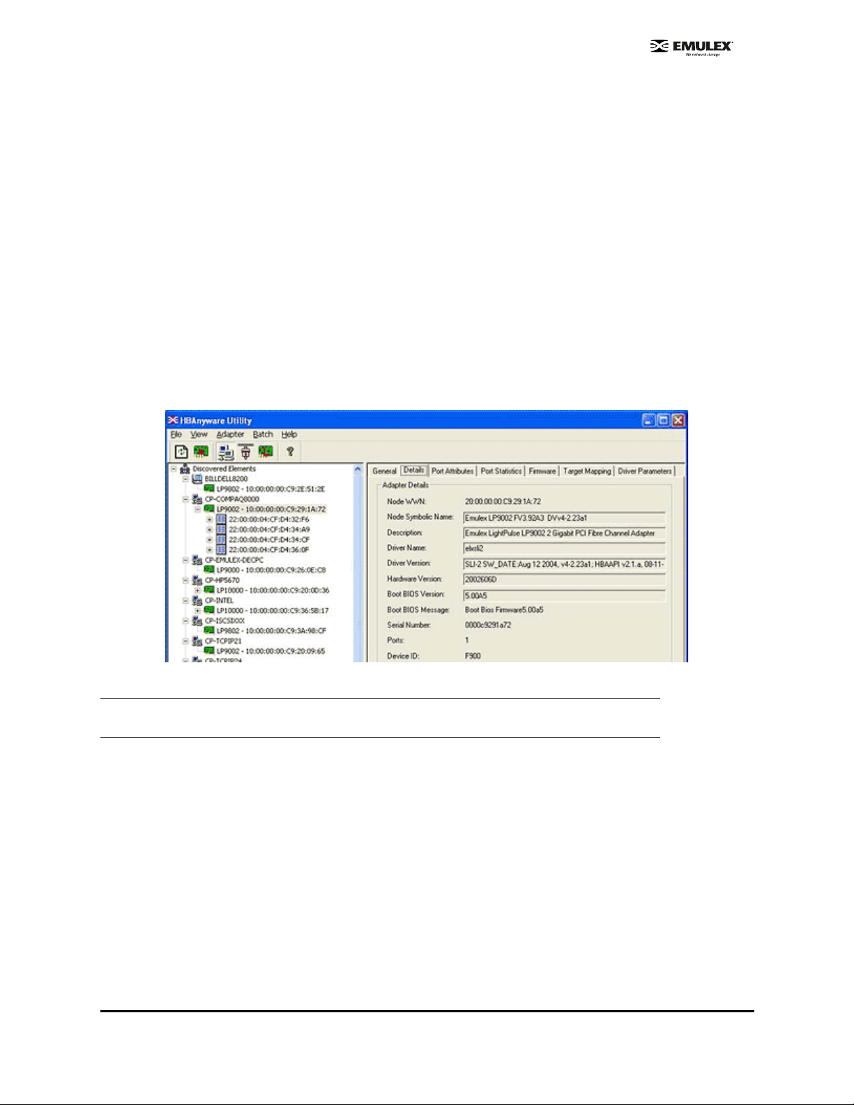
• User offline - the HBA is down or not connected to th e network.
• Bypassed - the HBA is in FC discovery mode.
• Dia gnostic M ode - the HBA is con trolled by a d iagnostic program .
• Link Down - there is no access to the network.
• Port Error - the HBA is in an unkno wn state; try resetting it.
• Loopba ck - an F C-1 mode in which inform ation passed to the FC-1 transm itter is
shunted directly to the FC-1 receiver. When a FC interface is in loopback mode, the
loopback signal overrides any external signal detected by the receiver.
• Unkno wn - the HBA is offline for an unknown reason.
• Resetting - the HBA is in the process of rebo oting.
• Downloa ding - a firm ware or other im age is bein g downloaded to the HBA.
View Detailed HBA Attributes
Once you have sorted the discovered HBAs, the Details tab contains detailed attributes associated with
the selected HBA.
Figure 20: HBAnyware, Detailed HBA Attributes
Note: Recessed fields indicate that the in formation in that field may exceed the text display area
of the field. Use the arrow keys on your keyboard to scroll and view additional information.
Adapter Details Field Definitions
• Node WWN - a 64-bit worldwide unique identifier assigned to the node.
• Node Symbolic Name - in a fabric, the name registered with the name server.
• Description - a formal description of the HBA, including model nu mber, bus type and link speed.
• Driver Name - an executable file image name for the driver as it appears in the Emulex driver
download package.
• Driver Version - the driver version number and the HBA application programming interface (HBA
API) version number.
• Hardware Version - the board version number, represented by the Joint Electronic Device
Engineering Council identifier (JEDEC ID), which is machine-readable from the Emulex
Application Specific Integrated Circuit (ASIC).
SCSIport Miniport Driver Configuration Section Page 38
Page 45
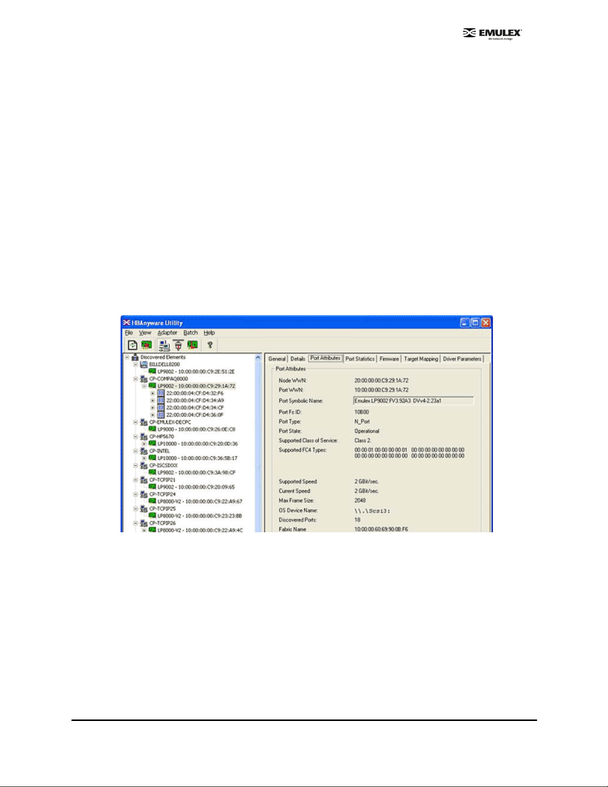
• Boot Bios Version - an optional read-only memory version number; displayed if the BootBIOS
bootup message is enabled on the HBA.
• Boot Bios Message - the enabled/disabled status of the BootBIOS message on the HBA. This
message is updated automatically if the status of the BootBIOS message changes (caused by
downloading a different firmware image). Possible messages are Not Present, Disabled, or the
FCode firmware version.
• Serial Number - the serial number assigned to the HBA when it was manufactured. Typically,
this is a Binary Coded Decimal (BCD) string of the 48-bit Institute of Electrical and Electronics
Engineers (IEEE) address for the HBA.
• Ports - the number of ports on the HBA. Currently, this is always one. The two ports of dualchannel HBAs are displayed in the discovery tree as two HBAs.
• Device ID - the HBA's default device ID.
• IEEE Address - the Media Access Control (MAC) address is in conformance with the FC Link
Encapsulation (FC-LE) standard. This address is a 48-bit number that is unique to every HBA in
existence. The IEEE Address is printed on a label affixed to one end of the HBA.
View Port Attributes
The Port Attributes tab contains information about the port on the selected HBA.
Figure 21: HBAnyware Port Attributes Tab
Port Attributes Field Definitions
• Node World Wide Name (WWN) - a 64-bit worldwide unique identifier assigned to the node. The
Node WWN is communicated during the login and port discovery processes. This identifier stays
with the entity for its lifetime.
• Port WWN - a 64-bit worldwide unique identifier assigned to the port. The identifier is
communicated during the login and port discovery processes and stays with the entity for its
lifetime.
• Port Symbolic Name - the name registered by the HBA with a name server. This field is
recessed, indicating that the information in this field may exceed the visible length of the field. If
necessary, use the arrow keys on your keyboard to scroll and view additional information.
• Port FC ID - FC ID for the port.
SCSIport Miniport Driver Configuration Section Page 39
Page 46

• Port Type - describes the current operational mode of the port.
• Port State - current status of the port: operational or link down.
• Supported Class of Service - a frame delivery scheme exhibiting a set of delivery characteristics
and attributes. There are three classes of service:
• Cla ss-1 provid es a dedicated co nnection betwee n a pair of ports with confirmed delivery or
notification of nondelivery.
• Cla ss-2 provid es a frame switched service with confirme d delivery or notification of
nondelivery.
• Class-3 provides a frame switched service similar to Class-2 but without notification of frame
delivery or non-delivery.
• Supported FC4 Types - a 256-bit (8-word) map of the FC-4 protocol types supported by the port.
Each bit in the map corresponds to a type value as defined by the FC standards and contained
in the Type field of the frame header.
• Supported Speed - maximum link speed supported by the HBA.
• Current Speed - link speed for the current session.
• Max Frame Size - maximum frame size.
• OS Device Name - a platform-specific name by which the HBA is known to the operating
system.
• Discovered Ports - number of facilities that provide FC interface attachment.
• Fabric Name or Host Name - the fabric name appears if you selected "Sort by Host Name". A
fabric name is a 64-bit worldwide unique identifier assigned to the fabric. Host Name a ppears if
you selected "Sort by Fabric ID". Host Name is the name of the host containing the HBA.
View Port Statistics
The Port Statistics tab provides cumulative totals for various error events and statistics on the port.
Statistics are cleared when the HBA is reset. Information fields that did not receive statistics data are
grey.
Figure 22: HBAnyware Port Statistics Tab
SCSIport Miniport Driver Configuration Section Page 40
Page 47

Port Statistics Field Definitions
• Tx Frames - FC frames transmitted by this HBA port.
• Tx Words - FC words transmitted by this HBA port.
• Tx KB Count - FC kilobytes transmitted by this HBA port.
• Tx Sequences - FC sequences transmitted by this HBA port.
• Link Failures - the number of times the link failed. A link failure is a possible cause of a timeo ut.
• Loss of Signal - the number of times the signal was lost.
• Invalid Tx Words - the total number of invalid words transmitted by this HBA port.
• Ex Count Orig - the number of FC exchanges originating on this port.
• LIP count - the number of loop initialization primitive (LIP) events that have occurred for the port.
This field is supported only if the topology is arbitrated loop. Loop initialization consists of the
following:
• Temporarily suspend loop operations.
• Determ ine whether loop capable ports are connected to the loop.
• Assign AL_PA IDs.
• Provide no tification of configur ation chan ges and loop failures.
• Pla ce loop p orts in the "monito ring" state.
• Network Operating System (NOS) count - this statistic is currently not supported for the
SCSIport Miniport and Storport Miniport drivers, nor is it supported for arbitrated loop.
• Rx Frames - the number of FC frames received by this HBA port.
• Rx Words - the number of FC words received by this HBA port.
• Rx KB Count - the received kilobyte count by this HBA port.
• Rx Sequences - the number of FC sequences received by this HBA port.
• Loss of Sync - the number of times loss of synchronization has occurred.
• Prim Seq Prot Errs - the primitive sequence protocol error count. This counter is in creme nted
whenever there is any type of protocol error.
• Invalid CRCs - the number of frames received that contain CRC failures.
• Ex Count Resp - the number of FC exchange responses made by this port.
• Error Frames - the number of frames received with cyclic redundancy check (CRC) errors.
• Dumped Frames - this statistic is not currently supported for the SCSIport Miniport driver, the
Storport Miniport driver or the driver for Solaris.
• Seconds Since Last Reset - the number of seconds since the HBA was last reset.
SCSIport Miniport Driver Configuration Section Page 41
Page 48

View Firmware Information
Use the Firmware tab to view current firmware versions and update firmware on remote and local HBAs.
The update procedure is on page 78.
Figure 23: HBAnyware Firmware Tab
Firmware Tab Field Definitions
• Firmware Version - the Emulex firmware version number for this model of HBA.
• Operational Firmware Name - if visible, the name of the firmware that is operat ional.
• SLI-1 Firmware Name - the name of the SLI-1 firmware overlay.
• SLI-2 Firmware Name - the name of the SLI-2 firmware overlay.
• Boot BIOS Message - the enabled/disabled status of the BootBIOS message on the HBA. This
message is updated automatically if the status of the BootBIOS message changes (caused by
downloading a different firmware image). Possible messages are Not Present, Disabled, or the
FCode firmware version.
Firmware File Maintenance
• Firmware File Name - the name of the firmware file to be download ed.
• Download in progress - this field appears as the firmware is being download.
Firmware Tab Buttons
• Enable/Disable - click to enable or disable the BootBIOS message for the HBA. Defaults to
disabled. If there is no BootBIOS present, this button is not available.
Note: If the state of the boot code message on the board has changed, this change will be
reflected immediately on the Details tab.
• Browse - click to browse through your files and locate the new firmware version to download.
• Download - click to update the HBA with the new firmware version.
SCSIport Miniport Driver Configuration Section Page 42
Page 49

View Target Mapping
Use this tab to perform mapping and persistent binding tasks. Procedures begin on page 70.
Figure 24: HBAnyware, Target Mapping Tab
Target Mapping Field Definitions
Current Settings Area
• Active Bind Type - WWPN, WWNN, or a destination identifier (D_ID).
• Automapping - current state of SCSI device automapping: enabled (default) or disabled.
Current Mappings
• This table lists current mapping information for the selected HBA.
Persistent Binding Configuration
• This table lists persistent binding information for the selected HBA.
Display Mode Radio Buttons
• Show WWPN
• Show WWNN
• Show D_ID
Target Mapping Buttons
• Change Settings - click to change the active bind type (the mode used to persistently bind
target mappings), LUN automapping or LUN unmasking settings. The Mapped Target Setting
window is displayed. Select the active bind type (WWPN, WWNN, D_ID or AL_PA), set LUN
automapping to enabled or disabled, and/or set LUN unmasking to enabled or disabled.
• Add Binding - click to add a persistent binding.
SCSIport Miniport Driver Configuration Section Page 43
Page 50

• Bind New - click to add a target that does not appear in the Persistent Binding table.
• Remove - click to remove the selected binding.
• Remove All - click to remove all persistent bindings that are displayed.
View Driver Parameters
The Driver Parameters tab allows you to view and modify driver parameters for the host or for an
individual HBA. For each parameter the tab displays the current value, the range of acceptable values,
the default value, and whether the parameter is dynamic (a dynamic parameter allows the change to
take effect without restarting the HBA or rebooting the system).
For information on specific parameter functionality, see page 52. For information on how to change
driver parameter values for the host, see page 46. For information on how to change driver parameter
values for an HBA, see page 47.
View Driver Parameters for an HBA
To view the driver parameters for an HBA:
• From the menu bar :
Click View, then Sort by Host Name.
or
• From the toolbar:
Click the button.
3. In the discovery tree, click the HBA. The General tab is displayed.
4. Click the Driver Parameters tab (Figure 25). The Installed Driver Types field shows the driver
version that is installed on the HBA.
Figure 25: HBAnyware, HBA Selected, Driver Parameters Tab
View Driver Parameters for a Host
To display the driver parameters for a host:
• From the menu bar :
• Click View, then Sort by Host Name.
or
• From the toolbar:
Click the button.
5. In the discovery tree, click the host. The Host Attributes tab is displayed.
6. Click the Host Driver Parameters tab (Figure 26). The Installed Driver Types drop-down box
shows a list of all driver types and driver versions currently installed on the HBAs in the host.
Figure 26: HBAnyware, Host Driver Pa rame ter s Tab
Driver Parameter Tab and Host Driver Parameter Tab Field Definitions
• Installed Driver Type - current driver and version installed.
• Adapter Parameter table - a list of parameters and their current values.
• Parameter-specific information - details about the parameter appear on the right side of the tab.
SCSIport Miniport Driver Configuration Section Page 44
Page 51

Driver Parameter Tab and Host Driver Parameter Tab Buttons
• Restore - click to restore parameters to this last saved value, if you have made changes to
parameters and have not saved them by clicking Apply.
• Use Defaults - click to set all parameter values to their default (out-of-box) values.
• Use Globals - click to set the selected parameter values to the last saved host parameter value.
• Apply - click to apply any driver parameter changes. The change may require a reboot or restart
of the system.
SCSIport Miniport Driver Configuration Section Page 45
Page 52

Setting Driver Parameters
Unattended Installation Scripts
If you are creating custom unattended installation scripts, any driver parameter can be modified and
included in the script.
Activation Requirements
The Driver Parameters tab in HBAnyware and the Driver Parameters category in lputilnt both contain
information for each parameter, including current, minimum, maximum, default parameter settings and
activation requirements.
• Dynamic - parameter can be changed and the change is effective while the system is running.
• Reset (HBAnyware)/Restart (lputilnt)- parameter change requires that the HBA be reset from the
utility before the change is effective.
• Reboot - parameter change requires that the entire machine be rebooted before the ch ange is
effective. If a parameter change requires a reboot, you are prompted to do so when you exit the
utility.
The Driver Parameter table on page 52 provides information for parameters that can be changed, and
includes allowable range of values and factory defaults. Parameters can be entered in decim al or
hexadecimal format.
Set Host Parameters Using HBAnyware
At the host level you can specify values for specific parameters. You can also set all parameters back to
the default value (out-of-box value).
Figure 27: HBAnyware, Host Driver Pa rame ter s Tab
Change Host Parameters
To change the host driver parameters:
1. Start HBAnyware.
2. In the discovery tree, select the host.
3. Click the Host Driver Parameters tab (Figure 27).
4. Click the driver parameter that you want to change. A description about the parameter appears
on the right side of the tab.
5. Change the parameter’s value. Some parameters allow you to enter a new value in decimal or
hexadecimal format, depending on how the current value is presented. If the va lue is in
hexadecimal format, it is prefaced by "0x", for example 0x2d, and if you change the valu e you
must enter it in hexadecimal format. Other parameters are enabled or disabled by radio buttons.
Still others offer pull down options.
6. If you want the change to be temporary (causing the parameter to revert to its last permanent
setting when the system is rebooted), check the "Make change temporary" box. This option is
available only for dynamic parameters.
7. If you are making changes to multiple parameters, and you want all the changes to be
temporary, check the "Make all changes temporary" box. This setting overrides the setting of the
"Make change temporary" box. Only dynamic parameters can be made temporary.
8. To apply your changes, click Apply.
SCSIport Miniport Driver Configuration Section Page 46
Page 53
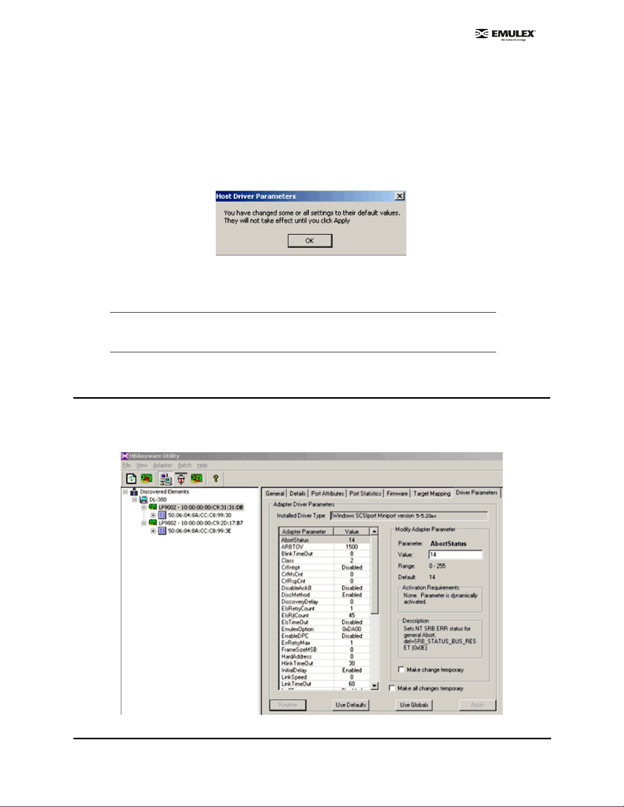
Reset Host Parameters
To reset all host driver parameters back to their default (out-of-box) va lues:
1. Start HBAnyware.
2. In the discovery tree, select the host.
3. Click the Host Driver Parameters tab.
4. Click Use Defaults. Parameters to be reset are displa yed in re d te xt. Th e Use Defaults button
is inactive and the following window is displayed:
Figure 28: Host Driver Parameters Response Win dow (fo r defa ults)
5. Click OK on the Host Driver Parameters tab. Parameters to be reset are still displayed in red
text. The value fields display the default values in red text as well.
Note: If you want to set all host driver parameters back to their value before you
clicked Use Defaults, click Restore. Restore will only work if you have not yet
clicked Apply.
6. On the Host Driver Parameters tab, click Apply.
Set HBA Driver Parameters Using HBAnyware
At the HBA level you can specify values for specific parameters. You can also set all parameters back to
the default value (out-of-box value). Additionally, you can set all parameters to the those values last
saved for the host.
Figure 29: HBAnyware, HBA Driver Parameters
SCSIport Miniport Driver Configuration Section Page 47
Page 54

To change an HBA’s parameter value:
1. In the discovery tree, click the HBA or the host.
2. Click the Driver Parameters tab.
3. Click the driver parameter that you want to change. A description about the parameter appears
on the right side of the tab.
4. Change the parameter’s value. Some parameters allow you to enter a new value in decimal or
hexadecimal format, depending on how the current value is presented. If the va lue is in
hexadecimal format, it is prefaced by "0x", for example 0x2d, and if you change the valu e you
must enter it in hexadecimal format. Other parameters are enabled or disabled by radio buttons.
Still others offer pull down options.
5. If you want the change to be temporary (causing the parameter to revert to its last permanent
setting when the system is rebooted), check the "Make change temporary" box. This option is
available only for dynamic parameters.
6. If you are making changes to multiple parameters, and you want all the changes to be
temporary, check the "Make all changes temporary" box. This setting overrides the setting of the
"Make change temporary" box. Only dynamic parameters can be made temporary.
7. To apply your changes, click Apply.
To reset all HBA driver parameters back to their default (out-of-box) valu es:
1. Start HBAnyware.
2. In the discovery tree, select the host.
3. Click the Driver Parameters tab.
4. Click Use Defaults. Parameters to be reset are displayed in red text. The Use Defaults button
is inactive and the following window is displayed:
Figure 30: HBA Driver Parameters Respo nse Wind ow ( fo r def au lts)
5. Click OK on the Driver Parameters tab. Parameters to be reset are still displayed in red text.
The value fields display the default values in red text as well.
Note: If you want to set all host driver parameters back to their value before you
clicked Use Defaults, click Restore. Restore will only work if you have not yet
clicked Apply.
6. On the Host Driver Parameters tab, click Apply.
To set an HBA parameter value(s) to the corresponding host parameter value(s):
1. Start HBAnyware.
2. In the discovery tree, select the HBA.
3. Click the Driver Parameters tab.
SCSIport Miniport Driver Configuration Section Page 48
Page 55

4. Click Use Globals. All displayed values are the same as the corresponding global, or host,
values. The Use Globals button is made inactive and the following window is displayed:
Figure 31: HBA Driver Parameters Response Window (for global values)
5. If you want the change to be temporary (causing the parameter to revert to its last permanent
setting when the system is rebooted), check the "Make change temporary" box. This option is
available only for dynamic parameters.
6. If you are making changes to multiple parameters, and you want all the changes to be
temporary, check the "Make all changes temporary" box. This setting overrides the setting of the
"Make change temporary" box. Only dynamic parameters can be made temporary.
7. To apply your changes, click Apply.
SCSIport Miniport Driver Configuration Section Page 49
Page 56

Set Parameters Using lputilnt
You can use lputilnt to change parameter values for the local HBA. You can also set all parameters back
to the default value (out-of-box value) for the local HBA.
To change a driver parameter using lputilnt:
1. Start lputilnt.
2. Select an HBA.
3. Select Driver Parameters from the category list.
Figure 32: lputilnt, Driver Parameter View
4. Double-click the parameter to edit. The Modify Driver Parameter window is displayed.
Figure 33: lputilnt, Modify Driver Parameter Window
5. In the New Value field, enter the new value. You can enter numbers in decimal or hexadecimal
format. Numbers in hexadecimal format must be prefaced by "0x", fo r example, 0x2 d.
6. If desired and available, make the change permanent or global.
SCSIport Miniport Driver Configuration Section Page 50
Page 57
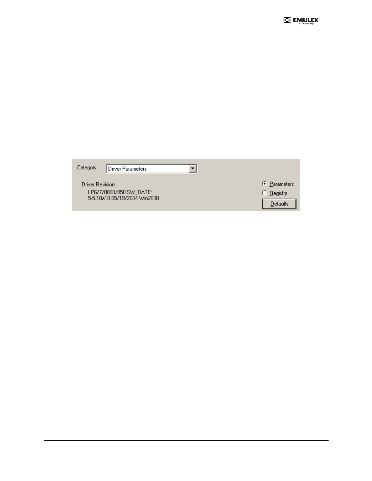
• Select the Perm anent che ck box to write the new value to the system registry. If the
Permanent check box is not selected, the parameter reverts to its last permanent setting
when the host is rebooted.
• Select the G lobal check box to chan ge the global re gistry entry. Otherwise, the change
affects the selected HBA only (Windows 2000 Server, Service Pack 3 or higher only).
7. Click OK.
Reset HBA Values
To reset all the local HBA driver parameters back to their default (ou t-of-box) values:
1. Start lputilnt.
2. Select an HBA.
3. Select Driver Parameters from the category list.
4. Make sure that the Parameters radio button is selected and click Defaults.
Figure 34: lputilnt, Defaults Button
5. A confirmation window is displayed. Click OK on the confirmation window to set all parameters
back to their defaults.
SCSIport Miniport Driver Configuration Section Page 51
Page 58

Driver Parameter Reference Table
Table 4: Driver Parameter Table
Parameter Definition
AbortStatus = 0xn AbortStatus controls the operating system SCSI request block (SRB)
error status when the Emulex driver must return a command to the
operating system for a general error condition. The default setting
causes completed commands to go up to the Microsoft class driver
level in Windows.
Value: 0x00 to 0xFF (hex)
Default = SRB_STATUS_BUS_RESET (0x0E)
Note: Unpredictable results may occur if this value is changed.
ARBTOV=n ARBTOV represents FC-AL arbitration timeout prior to LIP.
Value: 500 - 20000 milliseconds
Default = 1500
Note: Unpredictable results may occur if this value is changed.
BlinkTimeOut=n BlinkTimeOut controls the waiting time, in seconds, for the link to
come up during boot. This timer is only in effect at boot time.
Value: 1 - 30 seconds
Default = 8
Activation
Requirement
Dynamic
Restart
Reboot
Class=n Class is used to select the class of service on FCP commands.
If set to 1, class = 2.
If set to 2, class = 3.
Value: 1 - 2
Default = 2
CrfIntrpt=n This Coalesce Response Feature must be used in conjunction with
CrfMsCnt and CrfRspCnt. This feature allows the host bus adapter to
hold off from interrupting the host as long as the host has made
progress on the outstanding response queue during the last CrfMsCnt
period.
Value: 0 - 1
Default = 0
CrfMsCnt and CrfRspCnt work together to allow better CPU utilization
by processing multiple I/O responses per interrupt. Each time a
response is posted the host adapter compares the current response
count and, if it is greater than or equal to CoalesceRspCnt, an
interrupt posts. An interrupt also posts if, after CoalesceMsCnt
milliseconds, a response interrupt has not yet been posted. Zero
specifies immediate response notification.
Dynamic
Restart
SCSIport Miniport Driver Configuration Section Page 52
Page 59

Table 4: Driver Parameter Table (Continued)
Parameter Definition
CrfMsCnt=n This parameter specifies the time in milliseconds after which an
interrupt response is generated if CoalesceRspCnt has not been
satisfied. Zero specifies an immediate interrupt response notification.
A non-zero value enables response coalescing at the specified
interval in milliseconds.
Value: 0 - 63 (decimal) or 0x0 - 0x3F (hex) Default = 0
CrfRspCnt=n This parameter specifies the number of response entries after which
an Interrupt response is generated.
Value: 0 - 255 (decimal) or 0x0 - 0xFF (hex)
Default = 0
DisableAck0=n DisableAck0 determines Class 2 ACK_0 functionality.
If set to 0 = enabled.
If set to 1 = disabled (ACK_1 is used).
Value: 0 -1
Default = 0
DiscoveryDelay=n DiscoveryDelay controls whether the driver waits for ‘n’ seconds to
start port discovery after link up.
Activation
Requirement
Restart
Restart
Restart
Dynamic
If set to 0 = immediate discovery after link up.
If set to 1 or 2 = the number of seconds to wait after link-up before
starting port discovery.
Value: 0 - 7 seconds (decimal)
Default = 0 Setting this parameter >= 2 seconds helps device
availability with certain target vendors.
Note: Any target that enters PDISC pending state upon receipt of a
Fabric RSCN requires this parameter to be set >=2 seconds. Check
with your target vendor to determine if this is required.
DiscMethod=n If set to 0 = issues ADISC to check existence of nodes previously
logged in, before issuing PLOGI in discovery. Setting this parameter
to 0 may increase compatibility to tape drives.
If set to 1 = uses PLOGI only in discovery.
Value: 0 -1
Default = 1
ElsRetryCount = n ElsRetryCount controls how many retries are attempted when an
ELS_REQUEST (such as PLOGI, PRLI, etc.) fails.
Value:1 - 255
Default = 1
Dynamic
Dynamic
SCSIport Miniport Driver Configuration Section Page 53
Page 60

Table 4: Driver Parameter Table (Continued)
Parameter Definition
ElsRjtCount=n ElsRjtCount controls how to treat LINK_SERVICE_REJECTs with
either LOGICAL_BUSY/INVALID_NODE_NAME or
UNABLE_PROCESS/CMO_IN_PROCESS explanations. A non-zero
count allows these responses to be retried on a fixed 2-second
interval for up to the value specified.
Value: 0 - 255
Default = 45
ElsTimeOut=n ElsTimeOut controls whether the driver reinitializes the link when two
consecutive extended link service requests (such as PLOGI or PRLI)
time out.
If set to 1 = reinitialize link when two consecutive ELSs time out.
If set to 0 = no recovery action takes place. Device discovery will
continue.
Value: 0 -1
Default = 0
EmulexOption=n The EmulexOption hexadecimal value can be from 0x0 to
0x7FFFFFFF. n is a bit vector, one bit per option.
Windows Server 2003 and Windows 2000 Server
default=0x0000D200
Activation
Requirement
Dynamic
Dynamic
Reboot
See page 62 for more information on EmulexOption.
Note: Changing the Emulex Option default value is not
recommended unless you are running Windows 2000 Server
with Service Pack 3 or above.
EnableDPC=n If set to 0 = process I/O completion at interrupt level.
If set to 1 = process at DPC level.
Value: 0 - 1
Default = 0
ErrRetryMax=n ErrRetryMax specifies the number of retries while receiving an I/O
error (error attention 0x10000000 [SERR or PERR]). This value may
be 0 - 0xFFFFFFE.
If set to 0 = retry indefinitely.
If set to 1 = no retry.
If set to 2 = 0xFFFFFFE : number of retries + 1.
Value: 0 - 2
Default = 0x00000001
Dynamic
Dynamic
SCSIport Miniport Driver Configuration Section Page 54
Page 61

Table 4: Driver Parameter Table (Continued)
Parameter Definition
FrameSizeMSB=n FrameSizeMSB controls the upper byte of receive FrameSize if
issued in PLOGI. This allows the FrameSize to be constrained on
256-byte increments from 256 (1) to 2048 (8).
Value: 0 - 8
Default = 0
HardAddress=n HardAddress controls whether the driver maps addresses based on
WWPN or uses the target device's D_ID.
If set to 0 = map bus/target addresses to a WWPN.
If set to 1 = map bus/target addresses to fixed FC-AL hard address or
fabric D_ID, some hot swap applications can require HardAddress=1;.
Value: 0 - 1
Default = 0
HlinkTimeOut=0xn HlinkTimeOut measures how long the physical link is down.
HlinkTimeOut is a parameter that is nested inside of LinkTimeOut.
HlinkTimeOut measures the timeout from hardware link-down to
hardware link-up. If this timeout is exceeded, then the driver stops
issuing busy status for requests and starts to issue selection_timeout
error status. This value may be set smaller than LinkTimeOut as it
does not include port discovery. Setting this value to 0 causes the
timeout to occur after 0 seconds.
Activation
Requirement
Restart
Reboot
Dynamic
Value: 0 - 255
Default = 30
HostName=“name” This parameter is user-defined and may be used to specify the
Symbolic Node Name to be registered to the name server. The
Symbolic Node Name needs to be surrounded by double quotation
marks ("). It is limited to 32 characters in length.
InitialDelay=n InitialDelay controls whether the driver waits for two seconds to start
port discovery at the initial link up.
If set to 0 = don't wait 2 seconds at startup.
If set to 1 = wait 2 seconds at startup.
Value: 0 - 1
Default = 1
Reboot
SCSIport Miniport Driver Configuration Section Page 55
Page 62

Table 4: Driver Parameter Table (Continued)
Parameter Definition
LinkSpeed=n LinkSpeed has significance only if the HBA supports speeds other
than one Gbit.
If set to 0 = auto link speed detection.
If set to 1 = 1 Gbit.
If set to 2 = 2 Gbit.
If set to 4 = 4 Gbit.
If set to 16 = 10 Gbit.
Others = Reserved.
Value: 0 - 16 (see available options)
Default = 0
Note: Setting this option incorrectly may cause the HBA to fail to
initialize.
LinkTimeOut=n LinkTimeOut measures how long the physical link is down plus how
long it takes to discover remote devices. LinkTimeOut measures the
timeout at which the driver no longer “BUSYs” requests but issues
selection_timeout error status.If the timer expires before discovery
has completed, commands issued to timed out devices will return a
SELECTION_TIMEOUT. This LinkTimeOut value includes port login
and discovery time.
Activation
Requirement
Restart
Dynamic
Value: 1 - 500 seconds or 0x0 - 0xFE (hex)
Default = 60
Note: If UseAdisc is enabled (set to 1), LinkTimeOut is enabled. If
UseAdisc is disabled (set to 0), LinkTimeOut is disabled.
LipFFrecovery=n LipFFrecovery controls whether the driver issues a LIP when the link
has been down for LinkTimeOut/2.
If set to 0 = don't issue an LIP when LinkDownTime = LinkTimeOut/2.
If set to 1 = issue an LIP when LinkDownTime = LinkTimeOut/2 (helps
recover some older dual-port devices).
Value: 0 - 1
Default = 0
Dynamic
SCSIport Miniport Driver Configuration Section Page 56
Page 63

Table 4: Driver Parameter Table (Continued)
Parameter Definition
LogErrors=n LogErrors allows extra event messages to be logged in the Windows
System Event Log. Events logged by the Emulex SCSIport Miniport
driver will be Event ID 11 only. Other Event IDs (i.e. 9, 15) are not
logged by the Emulex SCSIport Miniport driver.
The Event ID 11 messages can be decoded by opening up the
message in Event Viewer and using the four bytes at offset 0x10 in
the Event Detail. These four bytes can be decoded using the t ab les in
the online Troubleshooting manual.
If set to 0 = do not log general adapter/disk errors.
If set to 1 = use the event log to log general errors.
Value: 0 - 1
Default = 0
MapNodeName=n MapNodeName controls whether the driver maps and tracks devices
based on WWPN or NodeName.
If set to 0 = map devices based on WWPN.
If set to 1 = map devices based on NodeName.
Value: 0 - 1
Default = 0
Activation
Requirement
Dynamic
Reboot
NodeTimeout=n NodeTimeOut controls the timeout at which a formerly logged in node
disappeared from the SAN. NodeTimeOut provides a delay in issuing
SRB_STATUS_SELECTION_TIMEOUT errors for nodes that have
disappeared from the SAN. After the timer expires, the driver makes
one more attempt to re-discover the device. If that fails, the driver
returns SRB_STATUS_SELECTION_TIMEOUT. The p ara mete r value
can be from 0 to 255 seconds. Setting this value to 0 causes the
timeout to occur after 0 seconds.
Value: 0 - 255 seconds or 0x0 - 0xFF (hex)
Default = 20
QueueAction=n If set to 0 = Windows Server 2003 or Windows 2000 Server
QueueAction (SIMPLE_QUEUE_TAG).
If set to 1 = QueueAction will be HEAD_OF_QUEUE_TAG.
If set to 2 = QueueAction will be ORDERED_QUEUE_TAG.
Value: 0 - 2
Default = 0
Note: Unpredictable results may occur if this value is changed.
Dynamic
Dynamic
SCSIport Miniport Driver Configuration Section Page 57
Page 64

Table 4: Driver Parameter Table (Continued)
Parameter Definition
QueueDepth=n QueueDepth requests per LUN/target (see QueueTarget parameter).
If the number of outstanding I/Os per de vice is expected to exceed 32,
the QueueDepth value needs to be increased to a value greater than
the number of expected I/Os per device (up to a value of 254). If the
QueueDepth value is set too low, there can be a performance
degradation due to driver throttling of its device queue.
Value: 1 - 255 or 0x1 - 0xFE (hex)
Default = 32 (0x20)
QueueIncStep=n If set to 0 = disable QueueDepth throttling down after queue full.
If set to 1 - 256 = number of increment step -1 after queue full is
automatically set to the number of outstanding requests -1. It begins
incrementing back according to this value every second until it gets
back to this original value (for example, if this setting is set to 1, the
QueueDepth value does not increment back).
Value: 0 -256
Default: 2
QueueTarget=n This parameter controls whether I/O depth limiting is on a per target or
per LUN basis.
If set to 0 = depth limitation is applied to individual LUNs.
If set to 1 = depth limitation is applied across the entire target.
Activation
Requirement
Dynamic
Dynamic
Value: 0 -1 or 0x0 - 0x1 (hex)
Default = 0 (0x0)
RegFcpType=n This parameter allows the driver to control whether the host appears
as an FCP type or a general device with no type in the NameServer
database.
If set to 1 = register the FCP type with the name server.
If set to 0 = does not register the FCP type with the name server.
Value: 0 - 1
Default = 1
Note: Unpredictable results may occur if this value is changed.
ResetFF=n ResetFF is used to force reservations to be freed when a ResetBus is
issued. This is meaningful only for FC-AL topology and Seagate
native FC disk drives.
If set to 0 = ResetBus action follows ResetTPRLO parameter
behavior.
If set to 1 = ResetBus action follows ResetTPRLO parameter behavior
and completes the action with LIP (FF).
Emulex recommends breaking reservations with Target Reset.
Value: 0 - 1
Default = 0
Dynamic
Dynamic
SCSIport Miniport Driver Configuration Section Page 58
Page 65

Table 4: Driver Parameter Table (Continued)
Parameter Definition
ResetTPRLO=n This parameter is used to handle a SCSI Reset Bus call from the
operating system. It is not recommended to change this value from it s
default or accepted OEM setting.
If set to 0 = Send Target Reset T ask Management comman ds to every
logged-in target device. Send FC aborts to all outst anding commands,
then re-establish a login to each target device with PLOGI and PRLI.
Link reinitialization is initiated only if ResetFF=1 (not recommended).
If set to 1 = Send TPRLO ELS command to every logged-in target
device with Global Process Logout bit = 1 and Type Code field = 8.
Link reinitialization is initiated only if ResetFF=1 (not recommended).
If set to 2 = Send FC aborts to all outstanding commands, then send
TPRLO to every logged-in target device with Global Process Logout
bit = 1 and Type Code field = 8. Link reinitialization is initiated only if
ResetFF = 1 (not recommended).
Value: 0 - 2
Default = 0
RetryNodePurge=n RetryNodePurge controls whether the driver causes port discovery
just prior to purging a node due to NodeTimeOut exceeded.
Setting this parameter to 1 allows the driver to retry discovery of a
node prior to purge. This option should be enabled for all hubs that do
not issue a LIP whenever a port is “un-bypassed”. The Emulex Digital
hub does not require this option to be enabled. This parameter value
can be set to 0 or 1.
Activation
Requirement
Dynamic
Dynamic
Value = 0 - 1
Default = 1
RTTOV=n R_T_TOV is the receiver-transmitter timeout as specified in the ANSI
FC standard. R_T_TOV represents the timeout between phases of
offline to online protocol.
Value = 100 - 255 milliseconds
Default = 100
Note: Unpredictable results may occur if this value is changed.
ScanDown=n If set to 0 = lowest AL_PA = lowest physical disk (ascending AL_PA
order).
If set to 1 = highest AL_PA = lowest physical disk (ascending SEL_ID
order).
Value: 0 - 1
Default = 1
Note: This option applies to private loop only in D_ID mode.
Restart
Reboot
SCSIport Miniport Driver Configuration Section Page 59
Page 66

Table 4: Driver Parameter Table (Continued)
Parameter Definition
SendEcho=n SendEcho controls whether the driver sends an echo frame to itself
every four seconds.
Setting this parameter to 1 allows early detection of a spurious hub
port bypass, and should be enabled for all hubs that do not issue a
LIP whenever a port is ‘un-bypassed’. The Emulex digital hub does
not require this option to be enabled.
Value: 0 - 1
Default = 0
SimulateDevice=n If set to 0 = don't create a ‘dummy’ disk device.
If set to 1 = create a dummy disk to force the driver to load if no disk
devices are present at boot time.
Value: 0 - 1
Default = 0
Note: Microsoft provides simulate device (CreateInitiatorLU)
functionality on Windows Server 2003 and it is enabled by default
during installation of the Emulex SCSIport Miniport driver, version
5.20a6. If you have a Windows Server 2003 system, use the simulate
device provided by Microsoft.
Activation
Requirement
Dynamic
Reboot
SnsALL=n SnsAll controls which N_Ports are queried from the NameServer.
If set to 0 = SCSI FCP only.
If set to 1 = all N_Ports.
Value: 0 - 1
Default = 0
TargetBlkSize=n TargetBlkSize specifies the number of 512-byte blocks to allocate for
an internal target RAM disk. This parameter is used in conjunction
with the TargetEnable SCSI Target Emulator feature (see
TargetEnable parameter definition).
Value: 0 - 16384
Default = 16384
Dynamic
SCSIport Miniport Driver Configuration Section Page 60
Page 67

Table 4: Driver Parameter Table (Continued)
Parameter Definition
TargetEnable=n TargetEnable allows the device driver to emulate a very simple SCSI
FCP target device. To other initiators, it will appear as a small disk
device of size TargetBlkSize/2 bytes. This is a very simple implementation and only supports basic SCSI operations. Because the
driver will also act as an initiator simultaneously through the same
host bus adapter, the small target device will appear in the Device
Manager/Disk Administrator on the host that is presenting the target.
This parameter was designed for the test environment.
If set to 0 = target disabled.
If set to 1 = target enabled from boot.
If set to 2 = target enabled after IOCTL.
Value: 0 - 2
Default = 0
Note: If target mode is enabled, FCP2 is disabled.
Topology=n Topology values may be 0 to 3.
If set to 0 (0x0) = FC-AL (loop).
If set to 1 (0x1) = PT-PT fabric.
If set to 2 (0x2) = *FC-AL first, then attempt PT-PT.
If set to 3 (0x3) = *PT-PT fabric first, then attempt FC-AL.
Activation
Requirement
Restart
* Topology fail-over requires v3.20 firmware or higher. If firmware
does not support topology fail-over, options 0,2 and 1,3 are
analogous.
Value: 0 - 3
Default = 2 (0x2)
TrafficCop=n If set to 1 = enable FC-AL loop master to run unfair and break
potential arbitration problems by sending frames to itself.
If set to 0 = run fair, no frames all the time.
Value: 0 - 1
Default = 0
Note: Unpredictable results may occur if this value is changed.
Restart
SCSIport Miniport Driver Configuration Section Page 61
Page 68

EmulexOption Detail
Those options with an asterisk (*) indicate that the option is enabled by default.
Table 5: EmulexOption Detail
Hexadecimal
Value
0x00000001 DISABLE_SCSI_BUSY. DISABLE_SCSI_BUSY prevents a SCSI_BUSY error from
0x00000002 LOG_STARTIO_ERRORS. Log all returned errors from STARTIO in the Event Log.
0x00000004 USE_BUS_RESET. This option is used only if DISABLE_SCSI_BUSY and
0x00000008 DISABLE_SCSI_QBUSY. DISABLE_SCSI_QBUSY prevents a SCSI_QUEUE_FULL.
0x00000010 DISABLE_SCSI_RSP_CHECK. Don't validate SCSI RSP field validity.
0x00000020 Reserved.
0x00000040 Reserved.
0x00000080 LIRP_DISABLE. This option does not allow LIRP/LILP loop init phase.
Description
changing the SRB status from SRB_STATUS_BUSY. errors.
DISABLE_SCSI_QBUSY are not set. USE_BUS_RESET allows the driver to return
SRB_STATUS_BUS_RESET instead of SRB_STATUS_BUSY.
errors.
0x00000100 HBA_RESET_DISABLE. Debugging option to prevent the driver from resetting the HBA.
0x00000200* VSA_ENABLE. Allow volume set addressing.
0x00000400 Reserved.
0x00000800 Reserved.
0x00001000
0x00002000
0x00004000*
0x00008000* SLIMPTR_ENABLE. This option enables firmware to use its memory for the host pointer
0x00010000 Reserved.
0x00020000 INDIV_RSTBUS. This option controls the SCSI bus reset to reset separate buses according
0x00040000 FDMI_ENABLE. This option enables FDMI support.
0x00000001 DISABLE_SCSI_BUSY. DISABLE_SCSI_BUSY prevents a SCSI_BUSY error from
0x00000002 LOG_STARTIO_ERRORS. Log all returned errors from STARTIO in the Event Log.
0x00000004 USE_BUS_RESET. This option is used only if DISABLE_SCSI_BUSY and
SERR & PERR Configuration. This is a 2-bit option. If this bit is set, bit 14 (0x00004000) will
be ignored.
Configure SERR & PERR as BIOS configured. If this bit is set, bit 13 (0x00002000) will be
ignored. 0 for this bit turns off SERR &PERR and 1 turns on the value for SERR& PERR.
instead of using host memory. This increases performance.
to the pathID from the upper layer . Disable th is option to a llow a si ngle bus reset to re set al l
SCSI buses (the standard mechanism in all previous releases).
changing the SRB status from SRB_STATUS_BUSY. errors.
DISABLE_SCSI_QBUSY are not set. USE_BUS_RESET allows the driver to return
SRB_STATUS_BUS_RESET instead of SRB_STATUS_BUSY.
SCSIport Miniport Driver Configuration Section Page 62
Page 69

SCSI Address Map
The driver emulates two SCSI busses and 128 targets on each bus to map 512 devices maximum.
The device mapping starts on either Bus 0 or Bus 1, depending on the driver EmulexOption parameter.
This table identifies the fixed mapping between Windows Server 2003 or Windows 2000 Server bus/
target/LUN and the Fibre Channel native address (AL_PA/SEL_ID). There are two potential mappings
based on the ScanDown parameter. Refer to the appropriate columns in the table below.
The index for the following table can be derived by:
#define TARGETS_PER_BUS 128
i = (Srb->PathId > 0) ? Srb->PathId-1 : 0; //Bus 0 = dummy bus
nodeInx = ((i * TARGETS_PER_BUS) + Srb-.TargetId) ;
* Use this translation if ScanDown = 0 (default)
** Use this translation if ScanDown = 1
** If bit 9 of EmulexOption = 0, then device addressing begins with Bus #0, not Bus #1
Table 6: SCSI Address Map
ScanDown = 0 (default) ScanDown = 1
BUS # TARGE T # LUN # AL_PA* SEL_ID * AL_PA** SEL_ID**
0 0-127 0-255 none none none none
1*** 0 0-255 0x01 0x7D 0xEF 0x00
1 0-255 0x02 0x7C 0xE8 0x01
2 0-255 0x04 0x7B 0xE4 0x02
3 0-255 0x08 0x7A 0xE2 0x03
4 0-255 0x0F 0x79 0xE1 0x04
5 0-255 0x10 0x78 0xE0 0x05
6 0-255 0x17 0x77 0xDC 0x06
7 0-255 0x18 0x76 0XDA 0x07
8 0-255 0x1B 0x75 0xD9 0x08
9 0-255 0x1D 0x74 0xD6 0x09
10 0-255 0x1E 0x73 0xD5 0x0A
11 0-255 0x1F 0x72 0xD4 0x0B
12 0-255 0x23 0x71 0xD3 0x0C
13 0-255 0x25 0x70 0xD2 0x0D
14 0-255 0x26 0x6F 0xD1 0x0E
15 0-255 0x27 0x6E 0xCE 0x0F
16 0-255 0x29 0x6D 0xCD 0x10
17 0-255 0x2A 0x6C 0xCC 0x11
SCSIport Miniport Driver Configuration Section Page 63
Page 70

Table 6: SCSI Address Map (Continued)
ScanDown = 0 (default) ScanDown = 1
BUS # TARGE T # LUN # AL_PA* SEL_ID * AL_PA** SEL_ID**
18 0-255 0x2B 0x6B 0xCB 0x12
19 0-255 0x2C 0x6A 0xCA 0x13
20 0-255 0x2D 0x69 0xC9 0x14
21 0-255 0x2E 0x68 0xC7 0x15
22 0-255 0x31 0x67 0xC6 0x16
23 0-255 0x32 0x66 0xC5 0x17
24 0-255 0x33 0x65 0xC3 0x18
25 0-255 0x34 0x64 0xBC 0x19
26 0-255 0x35 0x63 0xBA 0x1A
27 0-255 0x36 0x62 0xB9 0x1B
28 0-255 0x39 0x61 0xB6 0x1C
29 0-255 0x3A 0x60 0xB5 0x1D
30 0-255 0x3C 0x5F 0xB4 0x1E
31 0-255 0x43 0x5E 0xB3 0x1F
32 0-255 0x45 0x5D 0xB2 0x20
33 0-255 0x46 0x5C 0xB1 0x21
34 0-255 0x47 0x5B 0xAE 0x22
35 0-255 0x49 0x5A 0xAD 0x23
36 0-255 0x4A 0x59 0xAC 0x24
37 0-255 0x4B 0x58 0xAB 0x25
38 0-255 0x4C 0x57 0xAA 0x26
39 0-255 0x4D 0x56 0xA9 0x27
48 0-255 0x4E 0x55 0xA7 0x28
41 0-255 0x51 0x54 0xA6 0x29
42 0-255 0x52 0x53 0xA5 0x2A
43 0-255 0x53 0x52 0xA3 0x2B
44 0-255 0x54 0x51 0x9F 0x2C
45 0-255 0x55 0x50 0x9E 0x2D
46 0-255 0x56 0x4F 0x9D 0x2E
47 0-255 0x59 0x4E 0x9B 0x2F
48 0-255 0x5A 0x4D 0x98 0x30
SCSIport Miniport Driver Configuration Section Page 64
Page 71

Table 6: SCSI Address Map (Continued)
ScanDown = 0 (default) ScanDown = 1
BUS # TARGE T # LUN # AL_PA* SEL_ID * AL_PA** SEL_ID**
49 0-255 0x5C 0x4C 0x97 0x31
50 0-255 0x63 0x4B 0x90 0x32
51 0-255 0x65 0x4A 0x8F 0x33
52 0-255 0x66 0x49 0x88 0x34
53 0-255 0x67 0x48 0x84 0x35
54 0-255 0x69 0x47 0x82 0x36
55 0-255 0x6A 0x46 0x81 0x37
56 0-255 0x6B 0x45 0x810 0x38
57 0-255 0x6C 0x44 0x7C 0x39
58 0-255 0x6D 0x43 0x7A 0x3A
59 0-255 0x6E 0x42 0x79 0x3B
60 0-255 0x71 0x41 0x76 0x3C
61 0-255 0x72 0x40 0x75 0x3D
62 0-255 0x73 0x3F 0x74 0x3E
63 0-255 0x74 0x3E 0x73 0x3F
64 0-255 0x75 0x3D 0x72 0x40
65 0-255 0x76 0x3C 0x71 0x41
66 0-255 0x79 0x3B 0x6E 0x42
67 0-255 0x77A 0x3A 0x6D 0x43
68 0-255 0x7C 0x39 0x6C 0x44
69 0-255 0x80 0x38 0x6B 0x45
70 0-255 0x81 0x37 0x6A 0x46
71 0-255 0x82 0x36 0x69 0x47
72 0-255 0x84 0x35 0x67 0x48
73 0-255 0x88 0x34 0x66 0x49
74 0-255 0x8F 0x33 0x65 0x4A
75 0-255 0x90 0x32 0x63 0x4B
76 0-255 0x97 0x31 0x5C 0x4C
77 0-255 0x98 0x30 0x5A 0x4D
78 0-255 0x9B 0x2F 0x59 0x4E
79 0-255 0x9D 0x2E 0x56 0x4F
SCSIport Miniport Driver Configuration Section Page 65
Page 72

Table 6: SCSI Address Map (Continued)
ScanDown = 0 (default) ScanDown = 1
BUS # TARGE T # LUN # AL_PA* SEL_ID * AL_PA** SEL_ID**
80 0-255 0x9E 0x2D 0x55 0x50
81 0-255 0x9F 0x2C 0x54 0x51
82 0-255 0xAE 0x2B 0x53 0x52
83 0-255 0xA5 0x2A 0x52 0x53
84 0-255 0xA6 0x29 0x51 0x54
85 0-255 0xA7 0x28 0x4E 0x55
86 0-255 0xA9 0x27 0x4D 0x56
87 0-255 0xAA 0x26 0x4C 0x57
88 0-255 0xAB 0x25 0x4B 0x58
89 0-255 0xAC 0x24 0x4A 0x59
90 0-255 0xAD 0x23 0x49 0x5A
91 0-255 0xED 0x22 0x47 0x5B
92 0-255 0xB1 0x21 0x46 0x5C
93 0-255 0xB2 0x20 0x45 0x5D
94 0-255 0xB3 0x1F 0x43 0x5E
95 0-255 0xB4 0x1E 0x3C 0x3C
96 0-255 0xB5 0x1D 0x3A 0x60
97 0-255 0xB6 0x1C 0x39 0x61
98 0-255 0xB9 0x1B 0x36 0x62
99 0-255 0xBA 0x1A 0x35 0x63
100 0-255 0xBC 0x19 0x34 0x64
101 0-255 0xC3 0x18 0x33 0x65
102 0-255 0xC5 0x17 0x32 0x66
103 0-255 0xC6 0x16 0x31 0x67
104 0-255 0xC7 0x15 0x2E 0x68
105 0-255 0xC9 0x14 0x2D 0x69
106 0-255 0xCA 0x13 0x2C 0x6A
107 0-255 0xCB 0x12 0x2B 0x6B
108 0-255 0xCC 0x11 0x2A 0x6C
109 0-255 0xCD 0x10 0x29 0x6D
110 0-255 0xCE 0x0F 0x27 0x6E
SCSIport Miniport Driver Configuration Section Page 66
Page 73

Table 6: SCSI Address Map (Continued)
ScanDown = 0 (default) ScanDown = 1
BUS # TARGE T # LUN # AL_PA* SEL_ID * AL_PA** SEL_ID**
111 0-255 0xD1 0x0E/ 0x26 0x6F
112 0-255 0xD2 0x0D 0x25 0x70
113 0-255 0xD3 0x0C 0x23 0x71
114 0-255 0xD4 0x0B 0x1F 0x72
115 0-255 0xD5 0x0A 0x1E 0x73
116 0-255 0xD6 0x09 0x1D 0x74
117 0-255 0xD9 0x08 0x1B 0x75
118 0-255 0xDA 0x07 0x18 0x76
119 0-255 0xDC 0x06 0x17 0x77
120 0-255 0xE0 0x05 0x10 0x78
121 0-255 0xE1 0x04 0x0F 0x79
122 0-255 0xE2 0x03 0x08 0x7A
123 0-255 0xE4 0x02 0x04 0x7B
124 0-255 0xE8 0x01 0x02 0x7C
125 0-255 0xEF 0x00 0x01 0x7D
126 0-255 none none none none
127 0-255 none none none none
SCSIport Miniport Driver Configuration Section Page 67
Page 74

I/O Coalescing
I/O Coalescing is enabled and controlled by two driver parameters: CrfMsCnt and CrfRspCnt. The effect
of I/O Coalescing will depend on the CPU resources available on the server. When I/O Coalescing is
turned on, interrupts are batched, reducing the number of interrupts and maximizing the amount of
commands processed with each interrupt. For heavily loaded systems, this will provide better
throughput.
When I/O Coalescing is turned off (the default), each I/O is processed immediately causing one CPU
interrupt per I/O. For systems that are not heavily loaded, the default will provide better throughput. The
following table shows recommendations based upon the number of I/Os per HBA
Table 7: Recommended Settings for I/O Coalescing
!/Os > 26000 1 24 1
CrfMsCnt
The CrfMsCnt parameter controls the maximum elapsed time in milliseconds that the HBA will wait
before generating a CPU interrupt.The value range is 0 - 63 (decimal) or 0x0 - 0x3F (hex).The default is
0 and disables I/O Coalescing.
CrfRspCnt
The parameter controls the maximum number of responses to be batched before an interrupt is
generated. If the time is passed, an interrupt will be generated for all responses collected up to that
point. If is set to less than 2, response coalescing is disabled and an interrupt is triggered for each
response. The value range for is 0 - 255 (decimal) or 0x0 - 0xFF (hex). The defa ult valu e is 0.
Note: A system restart is required to make changes to effective.
For more information on using the HBAnyware or lputilnt utilities to change driver parameter values, see
“Setting Driver Parameters” on page 46.
Topology
The presence of a fabric is detected automatically.
Table 8: Topology Reference
HBAnyware
Topology Description
Private Loop
Operation
FC-AL (Loop) topology only is used. After successful loop initialization,
the driver attempts login with FL_PORT (Switched Fabric Loop Port).
• If FL_PORT login is successful, public loop operation is employed.
• If FL_PORT login is unsuccessful, private loop mode is entered. If a
fabric is not discovered and the topology is arbitrated loop, the driver
operates in private loop mode using the following rules:
• If an FC-AL device map is present, each node described in the map
is logged and verified to be a target.
• If an FC-AL device map is not present, logins are attempted with all
126 possible FC-AL addresses. LPGO/PRLO are also handled by
the driver. Reception of either causes a new discovery or login to
take place.
and lputilnt
Value
0
SCSIport Miniport Driver Configuration Section Page 68
Page 75

Table 8: Topology Reference
Topology Description
HBAnyware
and lputilnt
Value
Switched Fabric
Operation
*FC-AL attempt
first, then attempt
point-to-point.
*point-to-point
fabric attempt
first, then attempt
FC-AL.
• If F_PORT (point-to-point) login is successful, fabric mode is used.
• If F_PORT login is unsuccessful, N_PORT-to-N_PORT direct
connection topology will be used.
• If a switch is discovered, the driver performs the following tasks:
• FL_PORT login (Topology = 0;).
• F_PORT login (Topology =1;).
• Simple Name Server login.
• State Change Registration.
• Symbolic Name Registration.
• FCP Type Registration if RegFcpType is set to 1.
• The driver logs out and re-logs in. The name server indicates
that registration is complete.
• Simple Name Server Query for devices (the registry
parameter SnsAll determines whether all N_Ports are requested
(SnsALL=1;) or only SCSI FCP N_Ports (SnsAll=0; default)
• Discovery/device creation occurs for each target device
described by the Name Server.
• RSCN and LOGO/PRLO are handled by the driver. Reception
of either causes new discovery/logins to take place
• Topology fail-over requires v3.20 firmware or higher. If firmware is used
that does not support topology fail-over, options 0 and 2 are analogous.
Options 1 and 3 are analogous.
• Topology fail-over requires v3.20 firmware or higher. If firmware is used
that does not support topology , fail-over option s 0 and 2 are analogous.
Options 1 and 3 are analogous.
1
2
3
1: This driver is "Soft-Zone-Safe".
2: In a fabric environment, the order that disk devices are created is based upon the name server response data
(which is not guaranteed to be in any special order). Between successive boots, the same device may be identified
with a different physical device number. However, any devices which have been assigned a device letter through
disk administrator continue to use that letter regardless of the physical device number.
Set Topology Using HBAnyware
The Driver Parameters tab allows you to change the topology for a single HBA or for all HBAs that are
in one host.
To change topology:
1. In the discovery tree, click the HBA or the host.
2. Click the Driver Parameters tab.
3. Click the Topology parameter.
4. Select a new value from the drop-down list.
5. Click Apply.
6. Reset the HBA to make this change effective.
SCSIport Miniport Driver Configuration Section Page 69
Page 76

Set Topology Using lputilnt
To change topology:
1. Select an HBA.
2. Select Driver Parameters from the category list.
3. Double-click on Topology and the Modify Driver Parameter window is displayed.
4. Enter new topology value in the New Value field and click Change.
5. Reset the HBA to make this change effective.
Mapping and Masking Tasks
Automap SCSI Devices
The driver defaults to automatically mapping SCSI devices. The procedures in this se ction app ly if the
default has been changed.
Automap SCSI Devices Using HBAnyware
To automap SCSI devices:
1. Display driver parameters for the host or HBA - click the Driver Parameters tab or the Host
Driver Parameters tab .
2. Select the AutoMap HBA parameter. Several fields appear about the parameter on the right side
of the screen.
3. Select the Enabled radio button.
4. If you want the change to be temporary (causing the parameter to revert to its last permanent
setting when the system is rebooted), check the "Make change temporary" box. This option is
available only for dynamic parameters.
5. If you are making changes to multiple parameters, and you want all the changes to be
temporary, check the "Make all changes temporary" box. This setting overrides the setting of the
"Make change temporary" box. Only dynamic parameters can be made temporary.
6. To apply your changes, click Apply.
7. Reboot the system for this change to take effect.
SCSIport Miniport Driver Configuration Section Page 70
Page 77

Automap SCSI Devices Using lputilnt
To automap SCIS devices:
1. Start lputilnt.
2. Select an HBA.
3. Select Driver Parameters from the category list.
4. Double-click on Automap and the Modify Driver Parameter window is displayed:
5. Enter new automap value in the New Value field and click Change.
6. Reboot the system for this change to take effect.
Target and LUN Mapping and Masking Tasks Using lputilnt
Overviews
Globally Automap All Targets
Global Automap All Targets defaults to enabled to allow the Emulex driver to detect all FC device s
attached to the Emulex HBAs. Global automapping assigns a WWPN, target ID, SCSI bus and SCSI ID
to the device. The SCSI bus and SCSI ID may change when the system is rebooted. When persistent
binding is applied to one of these targets, the SCSI bus and SCSI ID remain the same, whether the
system is rebooted or Global Automap All Targets is enabled.
If Global Automap All Targets is disabled, the Emulex driver detects FC devices attached to the HBA,
and does not pass them to the operating system unless they are already persistently bound.
Globally Automap All LUNs
Global Automap All LUNs defaults to enabled and assigns an operating system LUN ID to a FC LUN ID
for all LUNs behind the targets in your SAN. LUN mapping can also be enabled and disabled at the
target level.
Global automapping of LUNs is different from persistent binding. Global LUN automapping does not
concern itself with the SCSI ID or SCSI Bus. This is because the global LUN mapping will stay the same
for the target when the system is rebooted.
Globally Unmask All LUNS
Globally Unmask All LUNs defaults to enabled, to allow the operating system to see all LUNS behind all
targets.
If Globally Unmask All LUNs is set to disabled and you want the operating system to see the LUNS
behind a specific target, you need to set unmasking at the target level.
Target LUN Automapping
Target LUN automapping defaults to disabled. If enabled, target LUN automapping assig ns operating
system LUN IDs to a fixed FC target's physical LUNs. Global LUN automapping must be disabled to do
target LUN automapping.
Target LUN automapping is different from persistent binding. Persistent binding assigns a WWPN of a
FC target device to an operating system target ID, SCSI bus and SCSI ID. The SCSI bus and SCSI ID
may change when the system is rebooted. When persistent binding is app lied to one of these target
devices, the SCSI bus and SCSI ID remain the same when the system is rebooted or global target
automapping is disabled.
LUN paths are displayed in Disk Manager (when you perform a re-scan) and are displayed dynamically
in HBAnyware.
SCSIport Miniport Driver Configuration Section Page 71
Page 78

Target LUN Masking
Target LUN masking defaults to disabled. You can mask and unmask LUNs at the target level. If you
have unmasked all LUNs for a specific target (either us in g the global or target functions), you can mask
and unmask an individual LUN as well. The HBA can detect all LUNs for the specific target and will
present only the unmasked ones.
Mapping and Masking Window Defaults
Table 9 describes LUN mappin g and masking global de faults.
Table 9: Mapping and Masking Window Defaults
Field (Function) Default Description Window
Globally Automap
All Targets
Globally Automap
All LUNs
Globally Unmask
All LUNs
Automap All
LUNs (Target
Level)
LUN Unmasking
(Targ et Level )
Enabled Emulex driver detects all FC devices attached to the
Emulex HBAs.
Enabled Assigns an operating system LUN ID to a FC LUN ID
for all LUNs behind all targets in the system area
network.
Enabled Allows the operating system to see all LUNs behind
all targets.
Disabled If Globally Automap All LUNs is disabled, this
parameter assigns an operating system LUN ID to a
FC LUN ID for all LUNs behind the selected target.
Disabled Allows the operating system to see all LUNs behind
the selected target. If this parameter is enabled, each
individual LUN can be masked or unmasked.
Global Automap
Global Automap
Global Automap
LUN Mapping
LUN Mapping
Mapping and Masking
The driver defaults to enabling global mapping and masking tasks. The procedures in this section apply
if the default has been changed.
Prerequisites
• SCSIport Miniport driver.
• Installed lputilnt.
• A target device with LUNs that have been properly configured.
• For automapping LUNS for a target, the Global Automap All LUNs setting on the Global
Automap window must be disabled. If necessary, disable this function and reboot the system
before automapping LUNS for a target.
Procedures
Globally Automap All Targets
Global Automap All Targets defaults to enabled to allow the Emulex driver to detect all FC device s
attached to the Emulex HBAs.
To globally automap all targets:
1. Select an HBA.
2. Select Persistent Bindings from the Category list.
SCSIport Miniport Driver Configuration Section Page 72
Page 79

3. Click Automap. The Global Automap window is displayed.
4. Change the Automap All Targets setting to Enabled.
5. Click OK. The window closes.
6. Reboot the system for this change to take effect.
Note: When persistent binding is applied to one o f these t arget s, the SC SI bus and SCSI ID
remain the same when the system is rebooted.
Globally Map All LUNs
Global Automap All LUNs defaults to enabled and assigns an operating system LUN ID to a FC LUN ID
for all LUNs behind the targets in your SAN. LUN mapping can also be enabled and disabled at the
target level.
To globally map all LUNs:
1. Select an HBA.
2. Select Persistent Bindings from the Category list.
3. Click Automap. The Global Automap window is displayed.
4. Change the Globally Automap All LUNs setting to Enabled.
5. Click OK. The window closes.
6. Reboot the system for this change to take effect
Globally Unmask or Mask All LUNs
Globally Unmask All LUNs defaults to enabled, to allow the operating system to see all LUNs behind
targets.
To globally unmask or mask all LUNS:
1. Select an HBA.
2. Select Persistent Bindings from the Category list.
3. Click Automap. The Global Automap window is displayed.
4. Change the Unmask All LUNs setting to Enabled.
5. Click OK. The window closes.
No reboot is required for this change to take effect.
Automap LUNs for a Target
Target LUN automapping defaults to disabled. If enabled, target LUN automapping assigns an operating
system LUN ID to a fixed FC target's physical LUN.
To automap LUNs for a target:
1. Select an HBA.
2. Select Persistent Bindings from the Category list. All targets are displayed.
3. Click on a target. The Lunmap button becomes active.
4. Click Lunmap. The LUN Mapping window is displayed.
5. Set the LUN Automap function to enabled. Target automapping assignment occurs and these
assignments are displayed on the LUN Mapping window.
6. Click OK.
7. Reboot the system for this change to take effect.
SCSIport Miniport Driver Configuration Section Page 73
Page 80

LUN Masking and Unmasking for a Target
Target LUN automapping defaults to disabled. If enabled, target LUN automapping assig ns operating
system LUN IDs to a fixed FC target's physical LUNs. Global LUN automapping must be disabled to do
target LUN automapping.
To unmask or mask a LUN:
1. Select an HBA.
2. Select Persistent Bindings from the Category list. All targets are displayed.
3. Click on a target. The Lunmap button becomes active.
4. Click Lunmap. The LUN Mapping window is displayed. All LUNs are displayed for the target.
5. Do one of the following:
• To unmask or mask all LUNs for the target, set the LUN Unmasking function to enabled.
• To mask or unmask a LUN, select the row and click Edit. In the Edit Map Entry area,
click on the Mask (Unmask) field to change the status.
Note: If LUNs are not displayed, LUN mapping has been disabled at the global level and
not enabled at the target level, or the LUNs have been masked at the global level.
6. Click OK.
No reboot is required for these changes to take effect.
Persistent Binding Introduction
Global automapping assigns a binding type, target ID, SCSI bus and SCSI ID to the device. The binding
type, SCSI bus and SCSI ID may change when the system is rebooted. When persistent binding is
applied to one of these targets, the WWPN, SCSI bus and SCSI ID remain the same, whether the
system is rebooted or whether Global Automap All Targets is subsequently disabled (enabled by default
in elxcfg). The binding information is permanent because it is stored in the Windows registry. The driver
refers to the binding information at bootup.
Persistent binding permanently maps a device to the following:
• Binding type - WWPN
• SCSI bus
• SCSI ID
You can se t up persiste nt binding usin g either lpu tilnt or HBAnywa re.
• lputilnt allows you to set up persistent binding on local HBAs only.
• HBAnyware allows you to set up persistent binding on remote and local HBAs.
SCSIport Miniport Driver Configuration Section Page 74
Page 81

Perform Binding Using HBAnyware
To set up persistent binding:
1. In the Directory Tree, click the HBA for which you want to set up persistent binding.
2. Click the Target Mapping tab. All targets are displayed.
Figure 35: HBAnyware, Persistent Binding
3. Target mappings are d isplayed by WWPN, WWNN, o r D_ID. In the Display M ode se ction,
choose the display mode you want to use.
4. If you want to change the Active Bind Type (the mode used to persistently bind target mappings)
or Automapping setting, click Change Settings. Select the Active Bind Type (WWPN, WWNN or
D_ID), and set Automapping to Enabled or Disabled.
To add a persistent binding:
1. In the Targets Table, click the target that you want to bind.
2. Click Add Binding. The Add Persistent Binding window is displayed.
Figure 36: HBAnyware, Add Persistent Binding Window
3. Select the Bind Type that you want to use (WWPN, WWNN or D_ID).
SCSIport Miniport Driver Configuration Section Page 75
Page 82
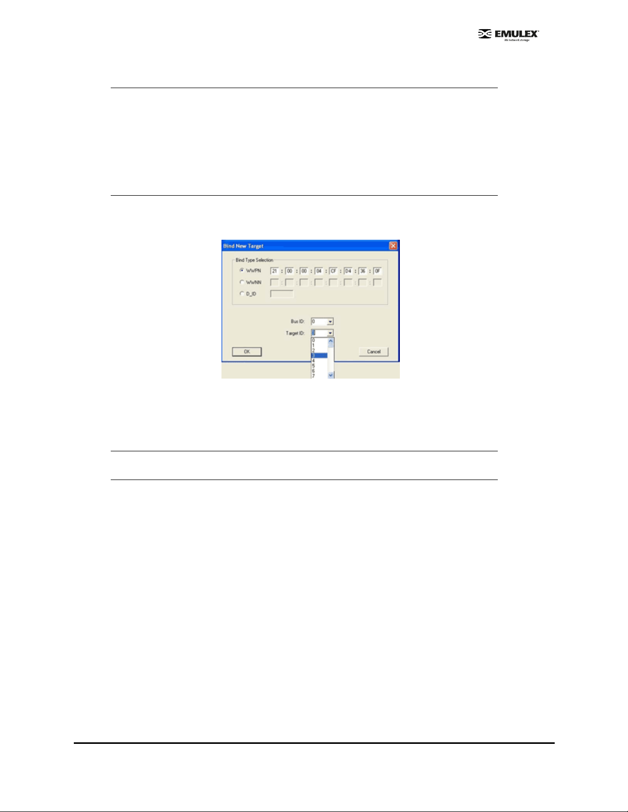
4. Select the Bus ID and Target ID that you want to bind, and click OK.
Note: Automapped target s will have entries onl y in th e second co lumn of the Targets Table.
Persistently bound targets will have entries in the second and third columns. In this
case, the third column contains the SCSI bus and t arget numbers you specified in the
Add Persistent Binding window. This binding will take effect only after the local
machine is rebooted.
It is possible to specify a SCSI bus and target that have already been used on beh alf
of a different FC target. HBAnyware does not detect this u ntil you cl ick the OK bu tton
in the Add window. Then a "duplicate binding" error message is displayed, and the
request is rejected.
To bind a target that does not appear in the Persistent Binding Table:
1. Click Bind New. The Bind New Target window is displayed.
Figure 37: HBAnyware, Bind New Target Window
2. Click the type of binding you want to use, and type the WWPN, WWNN or D_ID you want to bind
to the target.
3. Select the Bus ID and Target ID that you want to bind, a nd click OK.
Note: A target will not appear on the target list if automapping has been disabled and the
target is not already persistently bound.
Perform Binding Using lputilnt
To perform binding tasks:
1. Click Start, Programs, Emu lex an d lputilnt.
2. Select an HBA.
SCSIport Miniport Driver Configuration Section Page 76
Page 83

3. Select Persistent Binding from the Category list. All targets are displayed.
Figure 38: lputilnt, Persistent Bindings Cat egor y
4. Click on a target and click Add. The Add Binding window is displayed.
Figure 39: lputilnt, Add Binding Window
5. In the Unbound Targets list, click the target to be bound.
6. The bind type is displayed. The bind type is controlled by two driver parameters: Hard Address
and MapNodename. These parameters can be changed using the Driver Parameters window.
• HardAd dress - This parameter controls whether the driver ma ps addresses based on
WWPN, a fixed FC-AL hard address or a fabric D_ID.
• If set to 0 (defau lt), the driver m aps bus/target addresses a WWPN.
• If set to 1, the driver maps bus/target addresses to fixed FC-AL hard address or
fabric D_ID (some hot swap applications can require HardAddress=1)
• MapNode Name - This parameter controls whe ther the SCSIp ort Miniport driver m aps
and tracks devices based on WWPN or nodename. The HardAddress parameter must
be set to 0 for the MapNodeName parameter to be active.
• If set to 0 (defau lt), the driver m aps and tracks devices based on WWPN.
• If set to 1, the driver m aps and tracks devices b ase on Node name.
See “Set Parameters Using lputilnt” on page 50 for information on how to set these drive r
parameters.
7. If necessary, change the SCSI Bus and SCSI ID values.
SCSIport Miniport Driver Configuration Section Page 77
Page 84

8. Click OK, and the target is bound.The letters "PB" will be displayed next to the target row.
Figure 40: Persistent Binding Designation for Targets
9. Reboot the system for these changes to take effect.
10. Start lputilnt. Your new device and SCSI ID mapping information is displayed in the SCSI Target
List area.
Update Firmware
You can u pdate firm ware usin g either HBAnywar e or lputilnt.
• HBAnyware allows you to update firmware on remote and local HBAs.
• lputilnt allows you to update firmware on local HBAs only.
Update Firmware Using HBAnyware
Prerequisites
• The driver is installed properly.
• HBAnyware has been installed properly.
• The firmware file has been downloaded from the Emulex Web site and extracted to the Emulex
Repository folder (RMRepository). This folder is in the Program Files folder.
Procedures
Update Firmware
To update firmware:
1. Start HBAnyware.
2. In the discovery tree (left pane), click the HBA to which you want to update the firmware.
SCSIport Miniport Driver Configuration Section Page 78
Page 85

3. In the property tabs (right pane), select the Firmware tab.
Figure 41: HBAnyware Utility - Firmware Tab
4. On the Firmware tab, click Browse. The Select Firmware File browse window is displayed.
5. Browse to the Emulex Repository. Select the firmware file to download and click OK. A status
bar displays the progress of the download. During this time the HBA in the discovery tree is
displayed in red text, indicating that it is offline. It is displayed in black text when the update is
complete.
Repeat steps 2 - 4 to update the firmware on a second port.
Current Firmware Field Descriptions
Firmware Version - the Emulex firmware version number for this model of HBA.
Operational Firmware Name - if visible, the name of the firmware that is operational.
SLI-1 Firmware Name - the name of the SLI-1 firmware overlay.
SLI-2 Firmware Name - the name of the SLI-2 firmware overlay.
Note: If the state of the boot code message on the board has changed, this change will be
reflected immediately on the Details tab.
Update Firmware (Batch Mode) Using HBAnyware
Downloading firmware in batch mode allows you to install firmware on multiple HBAs in a single step.
Batch firmware loading is restricted to a single firmware file.
Note: No other HBAnyware functions can be performed while batch firmware loading is in progress.
To update firmware in batch mode:
1. From the menu bar, select Batch and click Download Firmware.
Note: You do not need to select a particular tree element for this operation.
2. When the Select Firmware File window is displayed, browse to locate and select the firmware
file to download. Click Open.
3. Click Open. A tree-view appears showing all HBAs and their corresponding hosts for which the
selected firmware file is compatible.
SCSIport Miniport Driver Configuration Section Page 79
Page 86
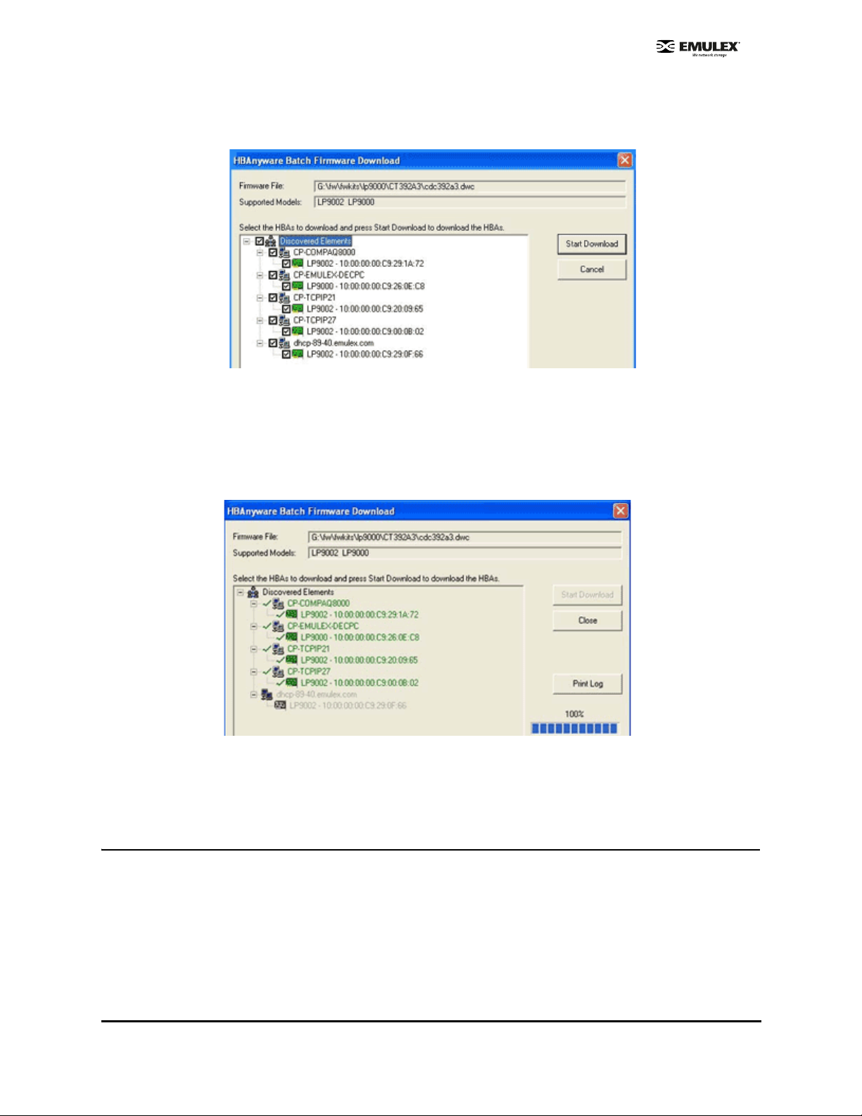
4. Click the box next to an HBA to select or remove that HBA from the batch process. Click the box
next to a host to select or remove all eligible HBAs for that host from the batch process
(Figure 42).
Figure 42: HBAnyware Batch Firmwar e Dow nlo ad Wind ow ( Partia l View), Se lect ing HB As to U pdate
5. When you have selected the HBAs on which you want to update the firm ware, click Start
Download.
6. After downloading begins, the tree-view displays the progress. As the file for a selected HBA is
being downloaded, it appears orange in the tree-view. After completion, the entry for the HBA
changes to green if the download succeeded or red if the download failed.
Figure 43: HBAnyware Batch Firmwar e D ownlo ad Wind ow, Download Complete
7. When downloading is complete, click Print Log for a hard copy of the activity log.
8. Click Close to exit the batch procedure.
Update Firmware Using lputilnt
Prerequisites
• The driver is installed properly.
• lputilnt is installed properly.
• The appropriate firmware file has been downloaded and unzipped to a local drive. Firmware has
been updated as needed.
• The system is in a state in which this type of maintenance can be performed:
SCSIport Miniport Driver Configuration Section Page 80
Page 87

• I/O activity on the bus has been quieted.
• Clu ster software, or any other software that relie s on the HBA to be available, has been
stopped or paused.
Caution: Firmware versions differ between HBA models. Make sure you have
downloaded the appropriate firmware for your HBA.
Procedure
To update firmware:
1. Click Start, Programs, Em ul ex and lputilnt .
2. Select the desired HBA.
3. Select Firmware Maintenance from the Category list.
Note: If the letter W appears next to a firmware entry, it indicates that the image is
represented in the wakeup parameters. This means that the HBA will use that
specific image if it needs a firmware image.
4. Click Download and locate the new firmware file.
5. Click Open.
6. The new firmware is transferred to flash ROM.
Update x86 BootBIOS
Update x86 BootBIOS Using HBAnyware
Prerequisites
• The driver is installed properly.
• HBAnyware has been installed properly.
• The file has been downloaded from the Emulex Web site and extracted to the Emulex
Repository folder (RMRepository). This folder is in the Program Files folder.
Procedures
Update x86 BootBIOS
To update x86 BootBIOS:
1. Start HBAnyware. If the x86 BootBIOS bootup message is enabled when you boot the system
(Firmware tab, button title is Disable - Figure 44), skip to step 2.
SCSIport Miniport Driver Configuration Section Page 81
Page 88
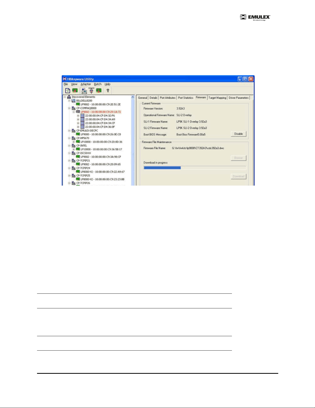
2. If the x86 BootBIOS bootup message is enabled when you boot the system (Firmwa re ta b ,
button title is Disable - Figure 44), skip to step 3. Otherwise continue with step a.
a. Click the HBA in the discovery tree (left pane).
b. Select the Firmware tab.
c. Click Enable. The button title changes from Enable to Disable.
Figure 44: HBAnyware Utility, Firmware Tab
d. If the x86 BootBIOS version that is installed is the most recent (Details tab, BootBIOS
Version field), enable x86 BootBIOS on HBAs using the Boot Utility (see page 9). Other
wise, continue with step 3.
3. Update the x86 BootBIOS File.
a. In the property tabs (right pane), select the Firmware tab.
b. On the Firmware tab, click Browse. The Select Firmware File browse window is
displayed.
c. Browse to the Emulex Repository. Select the file to download and click OK. During
downloading, the HBA in the discovery tree is displayed in red text, indicating that it is
offline. It is displayed in black text when the update is complete.
d. Repeat steps a through c to update the x86 BootBIOS on additional HBAs.
e. Reboot the system.
4. Enable x86 BootBIOS on HBAs using the BIOS Utility (see page 9).
Note: If the boot code message state on the board has changed, it is reflected immediately
on the Details tab.
Update x86 BootBIOS (Batch Mode)
Downloading x86 BootBIOS in batch mode allows you to install a file on multiple HBAs in a single step.
Batch loading is restricted to a single file.
Note: No other HBAnyware functions can be performed while batch firmware loading is in
progress.
-
SCSIport Miniport Driver Configuration Section Page 82
Page 89

To update x86 BootBIOS in batch mode:
1. Start HBAnyware.
2. From the menu bar, select Batch and click Download Firmware.
3. When the Select Firmware File window is displayed, browse to locate and select the x86
BootBIOS file to download.
4. Click Open. A tree-view appears showing all HBAs and their corresponding hosts for which the
selected file is compatible.
5. Click the box next to the HBA to select or remove that HBA from the batch processing. Click the
box next to a host to select to remove from the batch process (Figure 45).
Figure 45: Batch Firmware Download Wind ow, Selecting HBAs to Update
6. When you have selected the HBAs, click Start Download. After downloading begins, the treeview displays the progress. As the file for a selected HBA is being downloaded, it appears
orange in the tree-view. After completion, the entry for the HBA changes to green if the
download succeeded or red if the download failed.
Figure 46: Batch Firmware Download Window, Download Complete
7. When downloading is complete, click Print Log to get a hard copy of the activity log.
8. Click Close to exit the batch procedure.
SCSIport Miniport Driver Configuration Section Page 83
Page 90

Update x86 BootBIOS Using lputilnt
Prerequisites
• The driver is installed properly.
• lputilnt is installed properly.
• The system is in a state in which this type of maintenance can be performed:
• I/O activity on the bus has been quieted.
• Clu ster software, or any other software that relie s on the HBA to be available, has been
stopped or paused.
Procedure
To update x86 BootBIOS:
1. Start lputilnt.
2. If the x86 BootBIOS Bootup Message appears when you boot the system (Figure 47), skip to
step 2. Otherwise enable the x86 BootBIOS Bootup Message:
a. Select the desired HBA.
b. Select Firmware Maintenance from the Category list.
c. Select the BootBIOS image. If the BootBIOS image is not listed, you must lo ad x86
BootBIOS on the HBA.
d. Click Enable. The Enable button changes to Disable and the letter W appears to the left
of "Boot BIOS Firmware" in the Program Type list. This indicates that the x86 BootBIOS
is in use.
Figure 47: lputilnt, Program Type list
e. Exit the lputilnt utility.
f. If the x86 BootBIOS version that is installed is the most recent, skip to step 3. Other-
wise, continue with step 2.
3. Load an updated version of an x86 BootBIOS using lputilnt.
a. Ensure that the x86 BootBIOS file has been downloaded and extracted to a local drive .
b. Click Start, Programs, Emulex and lputilnt.
c. Select the desired HBA.
d. Select Firmware Maintenance from the Category list.
e. Click Download and locate the new file.
f. Click Open. The new boot code is transferred to flash ROM.
g. Exit the lputilnt utility.
h. Reboot the system.
4. Continue by enabling x86 BootBIOS on HBAs using the BIOS Utility (page 85).
SCSIport Miniport Driver Configuration Section Page 84
Page 91
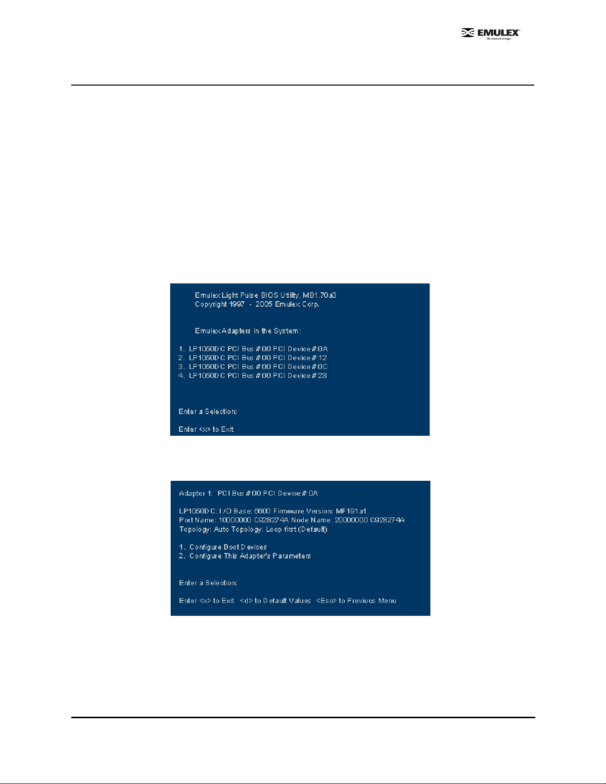
Enable x86 BootBIOS on HBAs Using the BIOS Utility
To use any of its features, x86 BootBIOS must be enabled on at lea st one installed HBA.
Prerequisites
• x86 BootBIOS is loaded on the HBA.
• x86 BootBIOS bootup message is enabled.
Procedure
To enable x86 BootBIOS on HBAs:
1. Boot the system.
2. Press <Alt E> immediately (within five seconds) when the x86 BootBIOS message is displayed
to start the BIOS utility. A menu displays a list of HBAs
3. Select the HBA by entering the appropriate number. In this example, entering 1 selects PCI
device 0A, 4 selects PCI device OA (Figure 48).
Figure 48: BIOS Utility, HBA Listing
The main configuration menu is displayed (Figure 4 9).
Figure 49: BIOS Utility, Main Configuration Menu
SCSIport Miniport Driver Configuration Section Page 85
Page 92
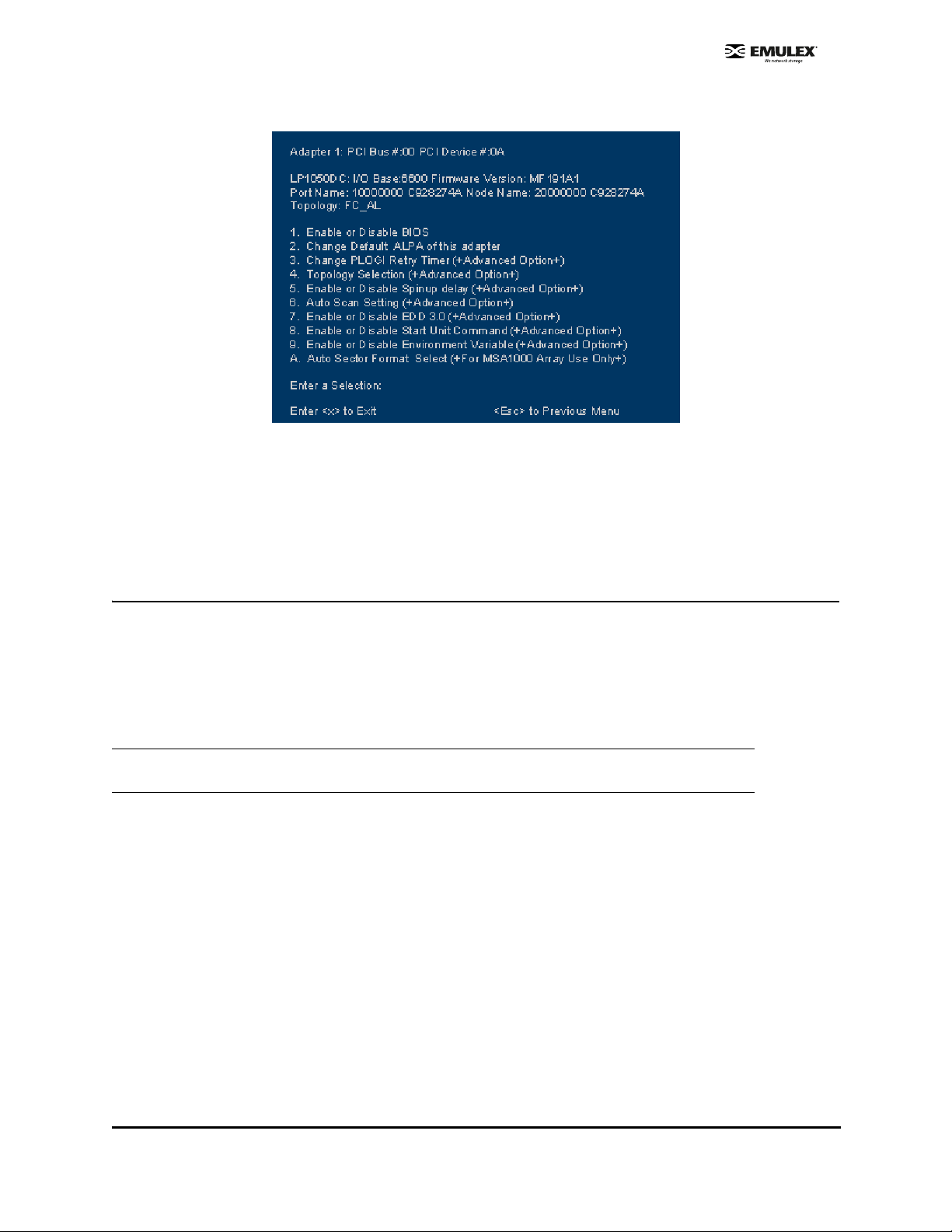
4. Press 2 to configure the HBA. The HBA configuration menu is displayed (Figu re 50).
Figure 50: BIOS Utility, HBA Configuration Menu
5. Press 1 to Enable or Disable BIOS.
6. Exit the BIOS utility and reboot the system.
Update EFIBoot
Update EFIBoot Using HBAnyware
Prerequisites
• The driver is installed properly.
• HBAnyware has been installed properly.
• The EFIBoot files have been downloaded from the Emulex Web site and extracted to the Emulex
Repository folder (RMRepository). This folder is in the Program Files folder.
Caution: If you are downloading EFIBoot on an HBA attached to the remote system disk, it is
recommended to use the EFI Utility to perform the download.
Procedure
To update EFIBoot:
1. Start HBAnyware.
2. In the discovery tree (left pane), click the HBA to which you want to load the firmware.
3. In the property tabs (right pane), select the Firmware tab.
4. On the Firmware tab, click Browse. The Select Firmware File browse window is displayed.
5. Browse to the Emulex repository. Select the EFIBoot file to download and click OK. A status bar
shows the progress of the download. During this time the HBA in the discovery tree is displayed
in red text, indicating that it is offline. It is displayed in black text when the update is complete.
6. Reboot the system.
SCSIport Miniport Driver Configuration Section Page 86
Page 93

If you are updating EFIBoot on a dual-channel HBA, repeat steps 2 through 5 to update EFIBoot on the
second port.
Note: If the state of the boot code message on the board has changed, this change will be
reflected immediately on the Details tab.
Update EFIBoot Using lputilnt
Prerequisites
• The driver is installed properly.
• The LightPulse utility (lputilnt) is installed properly.
• The EFIBoot file has been downloaded to a local drive.
Caution: If you are downloading EFIBoot on an HBA attached to the remote system disk, the
EFI utility is recommended to perform the download.
Procedure
To update EFIBoot:
1. Start lputilnt and select the desired HBA.
2. Select Firmware Maintenance from the Category list.
3. Click Download and locate the new EFIBoot file. Click Open.
4. The new boot code is transferred to flash ROM.
5. Exit the lputilnt utility and reboot the system.
SCSIport Miniport Driver Configuration Section Page 87
Page 94

HBAnyware Security
Introduction
After HBAnyware, which includes the HBAnyware utility and remote server, is installed on a group of
systems, the HBAnyware utility on any of those systems can remotely access and manage the HBAs on
any of the other systems. This may not be a desirable situation because any system can perform actions
such as resetting boards or downloading firmware.
The HBAnyware security package can be used to control which HBAnyware systems can remotely
access and manage HBAs on other systems in a FC network. HBAnyware security is systems-based,
not user-based. Anyone with access to a system that has been granted HBAnyware client access to
remote HBAs can manage those HBAs. Any unsecured system is still remotely accessible by the
HBAnyware client software (HBAnyware utility).
The HBAnyware security software is designed to provide two main security features:
• Prevent remote HBA management from systems in the enterprise that the adm inistra tor does
not want to have this capability.
• Prevent an accidental operation (such as firmware download) on a remote HBA. In this case, the
administrator does not want to have access to HBAs in systems he or she is not responsible for
maintaining.
The first time the HBAnyware Security Configurator (Security Configurator) is run on a syste m in an
environment where no security has been configured, the initial Access Control Group (ACG ) is created .
At this point, only this system has remote access to the HBAs in the systems in the ACG.
They are no longer remotely accessible from any other system. Subsequ ently, additional Access SubGroups (ASGs) can be created. This grants systems in the ACG the ability to remotely access the HBAs
of other selected systems in the ACG.
Start the Security Configurator
Prerequisites
• Before you can start the Security Configurator, you must have it installed on your system.
Note: Before you start the Security Configurator, you must make sure that all of the systems
that are part of, or will be part of, the security configuration are online on the FC network
so that they receive updates or changes made to the security configuration. Any system
already part of the security installation might not run with the proper security attributes if
updates to the security configuration are made while it is offli ne. Any system that is p art of
the security installation and that is offline when the Secu rity Configurator st art s wil l not be
available for security configuration changes even if it is brought online while the Security
Configurator is running.
SCSIport Miniport Driver Configuration Section Page 88
Page 95

Procedure
To start the Security Configurator:
1. On the desktop, click Start, then Programs , Emulex and HBAnyware Security Configurator.
The Discovery window is displayed.
Figure 51: HBAnyware Security Conf ig ur at or D i scove ry Windo w
2. After discovery completes, the main pane of the Security Configurator is displayed.
Figure 52: HBAnyware Security Co nf ig urat or M ain Wind ow
SCSIport Miniport Driver Configuration Section Page 89
Page 96

Run the Security Configurator for the First Time/Create the Access Control Group
When the HBAnyware Security software is installed on a system and the Security Configurator is run for
the first time, that system becomes the Master Security Client (MSC). All of the available servers are
discovered and available to become part of the system Access Control Group (ACG). Select the
systems to be added to the ACG, and the security configuration is updated on all of the selected servers
as well as on the initial system. This selection constitutes the participating platforms in this security
installation.
To create the ACG:
1. Start the Security Configurator for the first time in an unsecure environment. The computer from
which you run the Configurator will become the MSC. This message is displayed:
Figure 53: HBAnyware Security Conf ig ur at or M essag e
2. Click OK. The Access Control Group tab is displayed.
Figure 54: Access Control Group Tab, Example Before Security is Configured
SCSIport Miniport Driver Configuration Section Page 90
Page 97

3. Select the unsecured servers that you want to add to the ACG from the Available Servers list.
Figure 55: Access Control Group Tab Layout
4. Click the left arrow to add the servers to the Access Control Group Servers list.
5. Click OK or Apply.
Designate an Master Security Client
The first time you run the Security Configurator on any system in a FC network, that syste m becomes
the MSC.
SCSIport Miniport Driver Configuration Section Page 91
Page 98

Access Control Groups
The Access Control Group tab shows the systems that are part of a client's Access Control Group
(ACG) and, from the Master Security Client (MSC), allows you to select the systems that belong to the
ACG.
Access Control Group Tab on a Non-MSC
On a non-MSC system, the Access Control Group tab shows the systems that are part of the client's
ACG. You cannot modify the ACG on a non-MSC. (You can m odify the ACG only on the M SC or a client
higher in the security topology's hierarchy.) The Access Control Group tab on a non-MSC system looks
similar to Figure 56:
Figure 56: Access Control Group Tab on a non-MSC System
Access Control Group Tab on the MSC
On the MSC, you select or deselect the systems that you want to be part of the security installation in the
Access Control Group tab. When you select unsecure systems and move them to the Access Control
Group Servers list, these systems are updated to secure them and bring them into the MSC's ACG.
When you select systems in the ACG and move them to the Available Servers list, the security
configuration for those systems is updated to make them unsecure. After you have configured security
from the MSC for the first time, the Access Control Group tab looks similar to the following:
Figure 57: Access Control Group, Example After Security from the MSC is Configured
SCSIport Miniport Driver Configuration Section Page 92
Page 99

Table 10: Access Control Group-Specific Buttons
Button Title Corresponding Procedure
Remove Security Remove security from all servers in the ACG
Generate New Keys Generate new security keys.
Restore Restore the ACG to its last saved configuration.
ACG Icons
Depending on the configured security topology, a system can be a server in one or more ACGs. It can
also be a client to an ACG. The follow ing icons indicate th e state of each of the systems in the Acce ss
Control Group Servers list.
The system is a secure server in the ACG. It doe s not belo ng to an Access Sub-Gr oup (ASG). You
can remove this system from the ACG.
The system is a secure server in the ACG and belongs to one or more ASGs. You can remove this
system from the ACG.
The system is a secure server in the ACG and a client to an ASG. You cannot remove this system
from the ACG until you remove it as a client from the ASG.
The system is a secure server in the ACG, a secure server in one or more ASGs and a client to an
ASG. You cannot remove this system from the ACG until you remove it as a client from the ASGs.
The system is a Backup Master. You cannot remove this system from the ACG until you remove it as
a Backup Master.
SCSIport Miniport Driver Configuration Section Page 93
Page 100
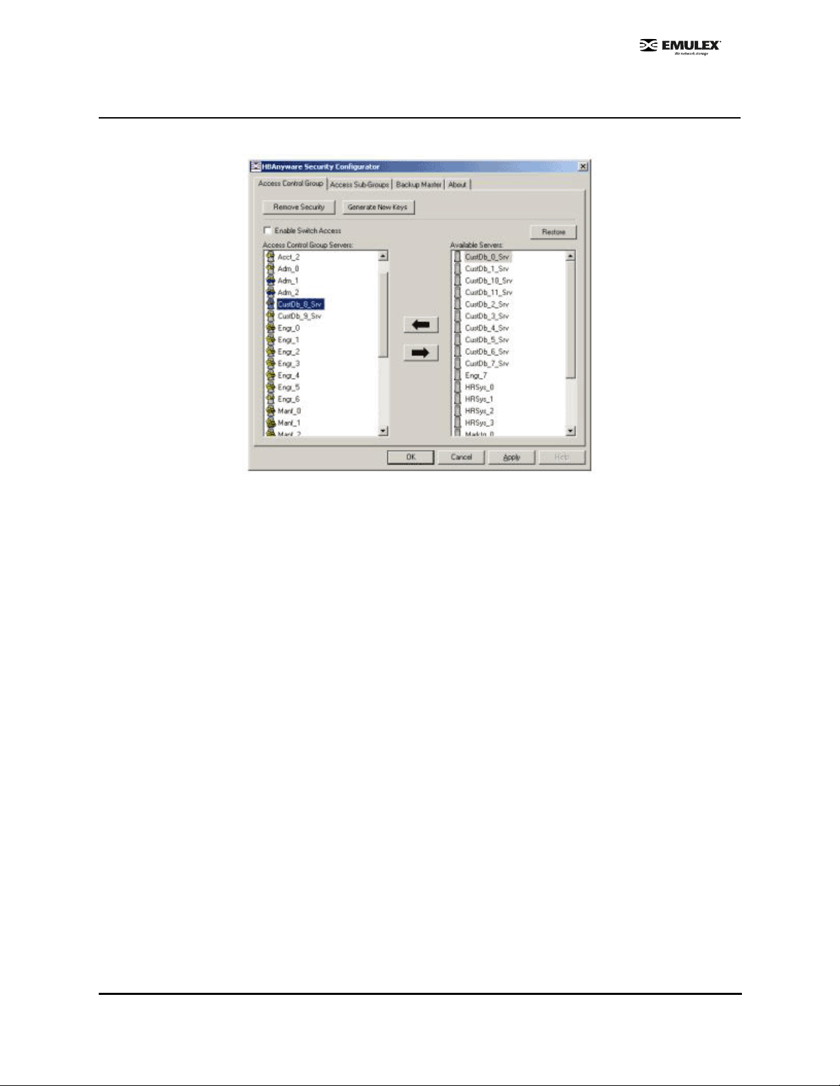
Access Control Group Tasks
The following tasks are performed on the Access Control Group tab.
Figure 58: Access Control Group Tab
Add a Server to the ACG
After you create the initial Access Control Group (ACG) on the Master Security Client (MSC), you may
want to add unsecured servers to the ACG.
To add servers to the ACG:
1. On the Access Control Group tab, from the Available Servers list, select the unsecured servers
that you want to add to the ACG.
2. Click the left arrow to add the server to the Access Control Group Servers list.
3. Click OK or Apply.
Delete a Server from the ACG
To delete a server from the Acce ss Control Gr oup (ACG):
1. On the Access Control Group tab, from the Access Control Group Servers list, select the
secured systems that you want to delete from the ACG.
2. Click the right arrow to remove the servers from the Access Control Group Se rvers list.
3. Click OK or Apply.
Remove Security from all Servers in the ACG
You can remove security from al l systems only from the Master Security Client (MSC). Removing the
entire security topology on all of the servers in the MSC's ACG puts the servers in an unsecure state.
The MSC is also put in an unsecure state; consequently, it is no longer the MSC. Any participating
systems that are not online will not receive the 'remove security' configuration update, and as a result
will no longer be accessible remotely.
SCSIport Miniport Driver Configuration Section Page 94
 Loading...