

Page 1

User Guide for
Emulex Printer Servers
Version 5.0
ER2054618-00
A
Page 2

Information contained in this document is believed to be accurate and reliable. However,
Emulex Corporation assumes no responsibility for its use nor for any infringements of patents
or other rights of third parties which may result from its use. Emulex Corporation reserves the
right to change product specifications at any time without notice.
The following trademarks of Emulex Corporation are used in this document:
The following are trademark acknowledgments:
Emulex
NETQue
NETQue Mate
NETQue Pro2
NETQue Token Ring
NETJet
rprint
enstall
UNIX is a trademark of AT&T Bell Laboratories
Novell and NetWare are trademarks of Novell Corporation
AppleTalk is a trademark of Apple Computer
Other brands and product names are trademarks of their respective companies.
This equipment has been tested and found to comply with the limits for a Class A digital
device, pursuant to part 15 of the FCC Rules. These limits are designed to provide reasonable
protection against harmful interference when the equipment is operated in a commercial
environment. This equipment generates, uses, and can radiate radio frequency energy and, if
not installed and used in accordance with the instruction manual, may cause harmful
interference to radio communications. Operation of this equipment in a residential area is
likely to cause harmful interference in which case the user will be required to correct the
interference at his own expense. Shielded cables must be used between this equipment and
attached peripheral devices. The reader is cautioned that changes or modifications made to
the equipment not expressly approved by Emulex could void the user’s authority to operate
this equipment.
The above statement applies to products marketed in the U.S.A.
This class A digital apparatus meets all requirements of the Canadian Interference - Causing
Equipment Regulations. Cet Appareil numerique de la classe A respecte toutes les exigences
du reglement sur le material brouilleur du Canada.
The above statement applies to products marketed in Canada.
Emulex Corporation
3535 Harbor Boulevard
Costa Mesa, CA 92626
Copyright © 1995 Emulex Corporation. All rights reserved worldwide. No part of this
document may be reproduced by any means nor translated to any electronic medium without
the written consent of Emulex Corporation.
Page 3

Table of Contents
CHAPTER 1 INTRODUCTION
OCUMENTATION .......................................................................................1-1
D
HECK CONTENTS ......................................................................................1-2
C
HECK MEDIA ............................................................................................1-3
C
CD-ROM ............................................................................................1-3
INCH DISKETTE ..............................................................................1-3
3.5
OW TO USE THIS GUIDE ...........................................................................1-4
H
SER GUIDE CONVENTIONS.................................................................1-4
U
HAT IS A COMMAND? .......................................................................1-4
W
ROMPTS .............................................................................................1-4
P
Keywords ......................................................................................1-4
Variables .......................................................................................1-5
Options..........................................................................................1-5
Quotation Marks............................................................................1-5
& PROTOCOL SUPPORT ...............................................................1-6
NOS
CHAPTER 2 PRINTER SERVER INSTALLATION
ET ......................................................................................................2-1
NETJ
EFERENCE NUMBERS.........................................................................2-1
R
NSTALLATION.....................................................................................2-2
I
CONNECTIONS & CABLING .........................................................2-3
LAN
Unshielded Twisted-Pair Connection............................................2-3
Thinwire BNC Connection............................................................2-4
ERIPHERAL CONNECTION...................................................................2-5
P
Serial Port......................................................................................2-5
OWER UP ...........................................................................................2-6
P
ISPLAY LIGHTS (LEDS).....................................................................2-6
D
RINT TEST PAGE ................................................................................2-7
P
RINT CONFIGURATION PARAMETERS .................................................2-7
P
ESET TO FACTORY DEFAULTS............................................................2-8
R
ACTORY DEFAULT CONFIGURATION..................................................2-9
F
RINTER SERVER SPECIFICATIONS.....................................................2-10
P
ECLARATION OF CONFORMITY ........................................................2-11
D
HAT’S NEXT? .................................................................................2-12
W
Configure NOS............................................................................2-12
Page 4

Table of Contents
ii
NETQ
NETQ
UE PRO2 ........................................................................................ 2-13
EFERENCE NUMBERS ...................................................................... 2-13
R
CONNECTIONS & CABLING ...................................................... 2-14
LAN
Unshielded Twisted-Pair Connection......................................... 2-14
Thinwire BNC Connection......................................................... 2-18
ERIPHERAL CONNECTIONS .............................................................. 2-16
P
Parallel Ports .............................................................................. 2-16
Serial Port................................................................................... 2-16
OWER UP......................................................................................... 2-17
P
ISPLAY LIGHTS (LEDS).................................................................. 2-18
D
RINT TEST PAGE.............................................................................. 2-19
P
RINT CONFIGURATION PARAMETERS .............................................. 2-20
P
Using Status Button.................................................................... 2-20
Using Software Command ......................................................... 2-20
ESET TO FACTORY DEFAULTS......................................................... 2-21
R
Reset Using Status Button.......................................................... 2-21
Reset Using Software Commands.............................................. 2-21
ACTORY DEFAULT CONFIGURATION ............................................... 2-22
F
RINTER SERVER SPECIFICATIONS .................................................... 2-23
P
ECLARATION OF CONFORMITY ....................................................... 2-24
D
HAT’S NEXT? ................................................................................ 2-25
W
Configure NOS........................................................................... 2-25
UE.................................................................................................. 2-26
EFERENCE NUMBERS ...................................................................... 2-26
R
CONNECTIONS & CABLING ...................................................... 2-27
LAN
Unshielded Twisted-Pair UTP Connection................................ 2-27
Thinwire BNC Connection......................................................... 2-28
ERIPHERAL CONNECTIONS .............................................................. 2-29
P
Parallel Port................................................................................ 2-29
Serial Port................................................................................... 2-29
OWER UP......................................................................................... 2-30
P
ISPLAY LIGHTS (LEDS).................................................................. 2-31
D
RINT TEST PAGE.............................................................................. 2-32
P
RINT CONFIGURATION PARAMETERS .............................................. 2-32
P
ESET TO FACTORY DEFAULTS......................................................... 2-33
R
ACTORY DEFAULT CONFIGURATION ............................................... 2-34
F
RINTER SERVER SPECIFICATIONS .................................................... 2-35
P
PTIONAL POWER SUPPLY SPECIFICATIONS ..................................... 2-36
O
ECLARATION OF CONFORMITY ....................................................... 2-37
D
HAT’S NEXT? ................................................................................ 2-38
W
Configure NOS........................................................................... 2-38
Page 5

Table of Contents
UE TOKEN RING..............................................................................2-39
NETQ
EFERENCE NUMBERS.......................................................................2-39
R
WITCH SETTINGS..............................................................................2-40
S
CONNECTIONS & CABLING .......................................................2-41
LAN
Unshielded Twisted-Pair UTP Connection.................................2-41
Shielded Twisted-Pair STP Connection......................................2-42
ERIPHERAL CONNECTIONS ...............................................................2-42
P
Parallel Port.................................................................................2-42
Serial Port....................................................................................2-43
OWER UP .........................................................................................2-43
P
ISPLAY LIGHTS (LEDS)...................................................................2-45
D
RINT TEST PAGE ..............................................................................2-46
P
RINT CONFIGURATION PARAMETERS ...............................................2-46
P
ESET TO FACTORY DEFAULTS..........................................................2-47
R
Reset Using Switch Settings .......................................................2-47
Reset Using Software Command ................................................2-48
ACTORY DEFAULT CONFIGURATION................................................2-49
F
RINTER SERVER SPECIFICATIONS.....................................................2-50
P
PTIONAL POWER SUPPLY SPECIFICATIONS ......................................2-51
O
ECLARATION OF CONFORMITY ........................................................2-52
D
HAT’S NEXT? .................................................................................2-53
W
Configure NOS............................................................................2-53
iii
CHAPTER 3 NOVELL NETWARE
EQUIREMENTS...........................................................................................3-1
R
INDERY MODE...................................................................................3-1
B
MODE..........................................................................................3-1
NDS
EFORE INSTALLATION...............................................................................3-2
B
HOOSE PSERVER OR RPRINTER...........................................................3-2
C
ONFIGURE AS PSERVER - NETWARE 1.2 TO 3.12 ...................................3-3
C
REATE THE PRINT QUEUE ..................................................................3-3
C
DD THE PRINTER SERVER ..................................................................3-4
A
DD THE PRINTER................................................................................3-4
A
ELECT THE PRINT QUEUE...................................................................3-4
S
ESTART THE PRINTER SERVER...........................................................3-5
R
ONFIGURE AS PSERVER - NETWARE 4.XX..............................................3-5
C
MODE REQUIREMENTS................................................................3-6
NDS
Create the Print Queue ..................................................................3-6
Add the Printer Server................................................................... 3-7
Add the Printer..............................................................................3-7
Select the Print Queue...................................................................3-7
Link Printer Server to Printer........................................................3-8
Restart the Printer Server ..............................................................3-8
Page 6

Table of Contents
iv
C
L
C
W
INDERY EMULATION MODE.............................................................. 3-9
B
Create the Print Queue ................................................................. 3-9
Add the Printer Server.................................................................. 3-9
Add the Printer........................................................................... 3-10
Select the Print Queue................................................................ 3-10
Restart the Printer Server ........................................................... 3-10
ONFIGURE AS RPRINTER..................................................................... 3-11
REATE THE PRINT QUEUE ............................................................... 3-11
C
DD THE REMOTE PRINTER .............................................................. 3-11
A
ELECT THE PRINT QUEUE................................................................ 3-12
S
ESTART THE PRINTER SERVER ........................................................ 3-13
R
286 Non-Dedicated Servers - VAP............................................ 3-13
386 Dedicated Servers - NLM.................................................... 3-13
Dedicated Printer Servers - 286 or 386...................................... 3-13
OGGING INTO THE PRINTER SERVER....................................................... 3-14
EMOTE LOGIN................................................................................. 3-14
R
OCAL LOGIN ................................................................................... 3-16
L
ONFIGURE SPECIFIC NETWARE PARAMETERS ....................................... 3-17
DD NETWARE PASSWORD TO PRINTER SERVER ............................. 3-17
A
EFINE THE PREFERRED NOVELL NETWARE FILE SERVER............... 3-18
D
EFINE THE METHOD OF DISCOVERY (NETWARE 4.XX)................... 3-18
D
EFINE THE NDS TREE ..................................................................... 3-19
D
EFINE THE POSITION OF THE PSERVER - NDS MODE ....................... 3-19
D
HAT’S NEXT?........................................................................................ 3-20
ONFIGURE NOS.............................................................................. 3-20
C
ANAGE WITH EMULEX NET WIZARD
M
PRINTER SERVER ADMINISTRATOR .................................................... 3-20
CHAPTER 4 UNIX
R
EQUIREMENTS.......................................................................................... 4-1
EFORE INSTALLATION.............................................................................. 4-2
B
UTOMATIC INSTALLATION....................................................................... 4-2
A
CD
D
ANUAL INSTALLATION............................................................................ 4-4
M
ARP.................................................................................................... 4-4
B
DHCP................................................................................................. 4-8
RARP................................................................................................. 4-9
ROM............................................................................................ 4-2
ISKETTE............................................................................................ 4-3
Change IP Address....................................................................... 4-4
Assign IP Address........................................................................ 4-5
Assign Symbolic Name................................................................ 4-6
OOTP................................................................................................ 4-7
Page 7

Table of Contents
ONFIGURE THE PRINT QUEUE ..........................................................4-10
C
Configure for BSD Hosts............................................................4-10
Configure a System V Host.........................................................4-13
LPD...................................................................................................4-16
Configure LPD on a BSD UNIX Host........................................4-16
Configure LPD for Non-UNIX Hosts.........................................4-18
LPSTAT............................................................................................4-19
ONFIGURE FOR SYSLOG SUPPORT ...........................................................4-19
C
OGGING INTO THE PRINTER SERVER........................................................4-21
L
EMOTE LOGIN..................................................................................4-21
R
OCAL LOGIN ....................................................................................4-23
L
HAT’S NEXT? ........................................................................................4-24
W
ONFIGURE NOS...............................................................................4-24
C
ANAGE WITH EMULEX NET WIZARD
M
PRINTER SERVER ADMINISTRATOR .....................................................4-24
CHAPTER 5 VAX/VMS DECNET
R
EQUIREMENTS...........................................................................................5-1
EFORE INSTALLATION...............................................................................5-1
B
RINTER QUEUES........................................................................................5-1
P
OGGING INTO THE PRINTER SERVER..........................................................5-3
L
EMOTE LOGIN....................................................................................5-3
R
OCAL LOGIN ......................................................................................5-4
L
HAT’S NEXT? ..........................................................................................5-6
W
ONFIGURE NOS.................................................................................5-6
C
ANAGE WITH EMULEX NET WIZARD
M
PRINTER SERVER ADMINISTRATOR .......................................................5-6
v
CHAPTER 6 APPLETALK
R
EQUIREMENTS...........................................................................................6-1
EFORE INSTALLATION...............................................................................6-1
B
ELECT PRINTER.........................................................................................6-1
S
OGGING INTO THE PRINTER SERVER..........................................................6-2
L
OCAL LOGIN ......................................................................................6-3
L
DVANCED APPLETALK PARAMETERS.......................................................6-4
A
ON BI-DIRECTIONAL PRINTERS.........................................................6-4
N
View Printer Fonts ........................................................................6-4
View Printer Server Fonts.............................................................6-5
Add Printer Server Fonts...............................................................6-5
Remove Printer Server Fonts ........................................................6-5
AGGED BINARY COMMUNICATION PROTOCOL...................................6-6
T
Page 8

Table of Contents
vi
HAT’S NEXT?.......................................................................................... 6-7
W
ONFIGURE NOS................................................................................ 6-7
C
ANAGE WITH EMULEX NET WIZARD
M
PRINTER SERVER ADMINISTRATOR ...................................................... 6-7
CHAPTER 7 LAN MANAGER
R
EQUIREMENTS.......................................................................................... 7-1
RINT MANAGER DISTRIBUTION FILES ...................................................... 7-1
P
EFORE INSTALLATION.............................................................................. 7-2
B
NSTALLATION ........................................................................................... 7-4
I
DD NEW PRINTERS .................................................................................. 7-4
A
TCP/IP
PROTOCOL.............................................................................. 7-6
Advanced Options........................................................................ 7-8
ETBIOS PROTOCOL........................................................................... 7-9
N
Advanced Options...................................................................... 7-10
RINTER TEST................................................................................... 7-11
P
HANGE OR DELETE PRINTERS ................................................................ 7-11
C
ELETE PRINTER............................................................................... 7-12
D
HANGE TCP/IP PRINTER’S PROPERTIES.......................................... 7-12
C
HANGE NETBIOS PRINTER’S PROPERTIES ....................................... 7-13
C
PTIONS MENU................................................................................. 7-14
O
TELRCF.................................................................................................. 7-15
ONFIGURE TELRCF ....................................................................... 7-15
C
SE TELRCF ................................................................................... 7-16
U
NTER SCRIPTS................................................................................. 7-16
E
HAT’S NEXT?........................................................................................ 7-18
W
ONFIGURE NOS.............................................................................. 7-18
C
ANAGE WITH EMULEX NET WIZARD
M
PRINTER SERVER ADMINISTRATOR .................................................... 7-18
CHAPTER 8 LAN SERVER
R
EQUIREMENTS.......................................................................................... 8-1
RINT MANAGER DISTRIBUTION FILES ...................................................... 8-1
P
EFORE INSTALLATION.............................................................................. 8-3
B
SERVER PRIOR TO 4.0................................................................. 8-3
LAN
SERVER 4.0................................................................................ 8-4
LAN
NSTALLATION ........................................................................................... 8-4
I
DD NEW PRINTERS .................................................................................. 8-5
A
TCP/IP
PROTOCOL.............................................................................. 8-6
Advanced Options........................................................................ 8-8
ETBIOS PROTOCOL........................................................................... 8-9
N
Advanced Options...................................................................... 8-11
Page 9

Table of Contents
TEST PRINTER....................................................................................8-12
HANGE OR DELETE PRINTERS .................................................................8-13
C
HANGE TCP/IP PRINTER’S PROPERTIES...........................................8-13
C
HANGE NETBIOS PRINTER’S PROPERTIES........................................8-14
C
ELETE PRINTER ...............................................................................8-14
D
PTIONS MENU..................................................................................8-15
O
TELRCF...................................................................................................8-15
ONFIGURE TELRCF........................................................................8-16
C
SE TELRCF....................................................................................8-17
U
NTER SCRIPTS..................................................................................8-17
E
HAT’S NEXT? ........................................................................................8-19
W
ONFIGURE NOS...............................................................................8-19
C
ANAGE WITH EMULEX NET WIZARD
M
PRINTER SERVER ADMINISTRATOR .....................................................8-19
CHAPTER 9 WINDOWS NT
R
EQUIREMENTS...........................................................................................9-1
EFORE INSTALLATION...............................................................................9-1
B
NSTALLATION ............................................................................................9-1
I
REATE A TCP/IP PRINTER ........................................................................9-4
C
NIQUE PRINTER QUEUE NAMES.........................................................9-7
U
RINTING TO WINDOWS NT FROM UNIX .................................................9-10
P
OGGING INTO THE PRINTER SERVER........................................................9-11
L
EMOTE LOGIN..................................................................................9-11
R
OCAL LOGIN ....................................................................................9-13
L
HAT’S NEXT? ........................................................................................9-14
W
ONFIGURE NOS...............................................................................9-14
C
ANAGE WITH EMULEX NET WIZARD
M
PRINTER SERVER ADMINISTRATOR .....................................................9-14
vii
CHAPTER 10 CONTACTING EMULEX
T
ECHNICAL ASSISTANCE...........................................................................10-1
RIOR TO YOUR CALL........................................................................10-1
P
LACING THE CALL............................................................................10-2
P
Domestic .....................................................................................10-2
European .....................................................................................10-2
- HOUR SUPPORT...........................................................................10-3
24
RODUCT SERVICE....................................................................................10-3
P
ULLETIN BOARD SYSTEM .......................................................................10-3
B
NTERNET..................................................................................................10-5
I
MUFAX ...................................................................................................10-6
E
Page 10

Table of Contents
viii
APPENDIX
C
A
G
ONNECTOR PINOUTS ...........A-ERROR! BOOKMARK NOT DEFINED.
THERNET UTP CONNECTOR PINOUT - RJ-45 ......................................A-
E
Error! Bookmark not defined.
OKEN RING UTP PINOUT - RJ-45....A-Error! Bookmark not defined.
T
T
OKEN RING STP PINOUT - FEMALE-DB9A-Error! Bookmark not defined.
ERIAL CONNECTOR PINOUT - MALE DB9 (DTE) ................................A-
S
Error! Bookmark not defined.
C
ONSOLE CONNECTOR PINOUT - RJ12 (DTE).......................................A-
Error! Bookmark not defined.
ARALLEL CONNECTOR PINOUT ....... A-Error! Bookmark not defined.
P
CRONYMS ................................................................................................A-7
LOSSARY .................................................................................................A-8
Page 11

Chapter 1
Thank you for purchasing an Emulex network product. You have joined the
Emulex family of users who have found that our products greatly facilitate
computer communication and the management of network resources. We
value a strong relationship with our customers and seek to serve your needs
in the years to come.
Emulex Corporation ( HQ ) ( 714 ) 662-5600
PreSales Support ( 714 ) 513-8053
Technical Support ( 714 ) 513-8270
New customers will find that the printer server can be used immediately
since the default printer server parameters are applicable to most networks.
Documentation
The documentation provides comprehensive guides detailing installation,
configuration and management of Emulex printer servers. This material is
either on CD-ROM or in hardcopy. Listed below are the guides and a brief
description of what they will help you accomplish.
Introduction
Printer Server User Guide
•
− Install printer server.
− Configure network operating system.
Command Reference Guide
•
− Understand proper syntax and use of printer server commands.
Software Upgrade Guide
•
− Upgrade Emulex printer server software.
• Emulex NET wizard printer server administrator User Guide
− Install Emulex
NET wizard printer server administrator.
Page 12

1-2 Chapter 1
− Configure printer servers - For example, add printers, assign trap
hosts, assign workgroups, upgrade printer server software, perform
memory image dumps, enable protocols, etc.
− Configure for NetWare - For example, choose PSERVER or
RPRINTER, choose frame type, perform rediscovery, create,
configure and assign print queues, etc.
Check Contents
• Emulex printer server
• Manuals: Manuals are available on the CD-ROM or in hardcopy.
− Printer Server User Guide
− Command Reference Guide
− Software Upgrade Guide
− Emulex NET wizard printer server administrator User Guide
• Warranty Registration Card
• Software utilities: CD-ROM or Diskette
• Power Supply
− NETJet - No power supply required
− NETQue and NETQue Token Ring - Power supply module
(transformer)
− NETQue Pro2 - AC power cord and selection guide
If any items are missing, please contact your local Emulex distributor.
Page 13

Introduction 1-3
Check Media
You have received software either on CD-ROM or diskette. Depending upon
the media enclosed, verify the contents:
CD-ROM
• On-Line Manuals
− Printer Server User Guide
− Command Reference Guide
− Software Upgrade Guide
− Emulex NET wizard printer server administrator User Guide
• Printer server software files:
Flash Update Utilities
UNIX Utilities (tar format)
TES Utilities for Netware (DOS format)
Microsoft OS/2 LAN Man Printer Manager (DOS format)
IBM OS/2 LAN Server Printer Manager (DOS format)
• Emulex
3.5 Inch Diskette
• Printer server software files:
Flash Update Utilities
UNIX Utilities (tar format)
TES Utilities for Netware (DOS format)
Microsoft OS/2 LANMan Printer Manager (DOS format)
IBM OS/2 LANServer Printer Manager (DOS format)
• Emulex
NET wizard printer server administrator software files
NET wizard printer server administrator software files
Page 14

1-4 Chapter 1
How to Use This Guide
This guide is designed to assist in the installation of your Emulex printer
server. The material contained in the guide is directed toward the network
administrator or the one responsible for a company’s computer network
needs.
User Guide Conventions
You will notice text boxes labeled NOTE or CAUTION.
• Notes provide additional information.
• Caution statements provide warnings to prevent harm to people or
equipment.
CAUTION:: Observe electrostatic discharge (ESD)
procedures during installation.
What is a Command?
A prompt, followed by a keyword and one or more variables, options or
quotation marks make up a command. The following explanation will
demonstrate command formatting.
Prompts
A prompt consists of the word Server followed by one or two greater than
symbols (>). One (>) indicates nonprivileged status and two (>>) signify
privileged or supervisor status. The two prompts are shown below:
Nonprivledged users have read only privileges. Privileged or supervisor users
have all read and write privileges.
Keywords
Server > (nonprivileged users)
Server >> (privileged users)
Keywords are enclosed in brackets and separated by vertical lines. The
user must enter a keyword to perform an action.
Server >>[set|define|change]
>
Page 15

Introduction 1-5
Variables
Variables are used as in mathematics: they represent a quantity, device name,
address or other entity. They are shown in bold italic type.
Server>>[set|define|change]server dhcp n m
>
n a variable
m a variable
Options
Options are used to customize a command. When available, the user should
always use options. They are italicized and enclosed in brackets.
Server>>[set|define|change]server dhcp n m
>
[temp][default]
temp an optional entry
default an optional entry
Quotation Marks
When case-sensitive information is required, it must begin and end with
quotation marks. Font names are case-sensitive and must appear in quotes
within command lines. The example below illustrates the use of a font name
within a command line.
Server>> change port 1 fonts add “Courier-Bold
>
Helvetica-Italics”
Page 16

1-6 Chapter 1
NOS & Protocol Support
With the recent release of printer server software version 5.0, we have
expanded the protocols supported by our existing line of Emulex printer
servers. Emulex printer servers can currently be used with these network
operating systems and protocols:
Novell Netware
TES, IPX/SPX
UNIX
TCP/IP, LPD, Telnet
Apple
EtherTalk
Apple
TokenTalk
VAX/VMS
DECnet LAT
Microsoft OS/2
LAN Manager
TCP/IP, LPD, NetBios
NETQue NQPro2 NETJet NQToken
IBM OS/2
LAN Server
TCP/IP, LPD, NetBios
Windows NT
TCP/IP, LPD
Page 17

Chapter 2
Printer Server
Installation
NETJET ................................................................................................................... 2-
R
EFERENCE NUMBERS.................................................................................................. 2-1
I
NSTALLATION.............................................................................................................. 2-2
LAN
CONNECTIONS & CABLING .................................................................................. 2- 3
NSHIELDED TWISTED-PAIR CONNECTION.......................................................... 2-3
U
HINWIRE BNC CONNECTION.............................................................................. 2-4
T
P
ERIPHERAL CONNECTION............................................................................................ 2-5
ERIAL PORT........................................................................................................ 2-5
S
P
OWER UP .................................................................................................................... 2-6
D
ISPLAY LIGHTS (LEDS).............................................................................................. 2-6
P
RINT TEST PAGE ......................................................................................................... 2-7
P
RINT CONFIGURATION PARAMETERS .......................................................................... 2-7
R
ESET TO FACTORY DEFAULTS .................................................................................... 2-8
F
ACTORY DEFAULT CONFIGURATION........................................................................... 2-9
P
RINTER SERVER SPECIFICATIONS.............................................................................. 2- 10
D
ECLARATION OF CONFORMITY................................................................................. 2-11
W
HAT’S NEXT? .......................................................................................................... 2-12
ONFIGURE NOS ............................................................................................... 2-12
C
NETQUE PRO2 ................................................................................................................. 2-
R
EFERENCE NUMBERS................................................................................................ 2-13
LAN
CONNECTIONS & CABLING ................................................................................ 2- 14
NSHIELDED TWISTED-PAIR CONNECTION........................................................ 2-14
U
HINWIRE BNC CONNECTION............................................................................ 2-15
T
P
ERIPHERAL CONNECTIONS........................................................................................ 2-16
ARALLEL PORTS............................................................................................... 2-16
P
ERIAL PORT...................................................................................................... 2-16
S
P
OWER UP .................................................................................................................. 2-17
D
ISPLAY LIGHTS (LEDS)............................................................................................ 2-18
1
13
Page 18

ii Chapter 2
PRINT TEST PAGE........................................................................................................2-19
P
RINT CONFIGURATION PARAMETERS.........................................................................2-20
SING STATUS BUTTON......................................................................................2-20
U
SING SOFTWARE COMMAND.............................................................................2-20
U
R
ESET TO FACTORY DEFAULTS ...................................................................................2-21
ESET USING STATUS BUTTON...........................................................................2-21
R
ESET USING SOFTWARE COMMANDS................................................................2-21
R
F
ACTORY DEFAULT CONFIGURATION..........................................................................2-22
P
RINTER SERVER SPECIFICATIONS...............................................................................2-23
D
ECLARATION OF CONFORMITY..................................................................................2-24
W
HAT’S NEXT?...........................................................................................................2-25
ONFIGURE NOS................................................................................................2-25
C
NETQUE .................................................................................................................2-
R
EFERENCE NUMBERS.................................................................................................2-26
LAN
CONNECTIONS & CABLING.................................................................................2-27
NSHIELDED TWISTED-PAIR UTP CONNECTION ................................................2-27
U
HINWIRE BNC CONNECTION ............................................................................2-28
T
P
ERIPHERAL CONNECTIONS.........................................................................................2-29
ARALLEL PORT .................................................................................................2-29
P
ERIAL PORT.......................................................................................................2-29
S
P
OWER UP...................................................................................................................2-30
D
ISPLAY LIGHTS (LEDS).............................................................................................2-31
P
RINT TEST PAGE........................................................................................................2-32
P
RINT CONFIGURATION PARAMETERS.........................................................................2-32
R
ESET TO FACTORY DEFAULTS ...................................................................................2-33
F
ACTORY DEFAULT CONFIGURATION..........................................................................2-34
P
RINTER SERVER SPECIFICATIONS...............................................................................2-35
O
PTIONAL POWER SUPPLY SPECIFICATIONS................................................................2-36
D
ECLARATION OF CONFORMITY..................................................................................2-37
W
HAT’S NEXT?...........................................................................................................2-38
ONFIGURE NOS................................................................................................2-38
C
26
Page 19

Printer Server Installation iii
NETQUE TOKEN RING.................................................................................................. 2-
R
EFERENCE NUMBERS................................................................................................ 2-39
S
WITCH SETTINGS ...................................................................................................... 2-40
LAN
CONNECTIONS & CABLING ................................................................................ 2- 41
NSHIELDED TWISTED-PAIR UTP CONNECTION................................................ 2-41
U
HIELDED TWISTED-PAIR STP CONNECTION..................................................... 2-42
S
P
ERIPHERAL CONNECTIONS........................................................................................ 2-42
ARALLEL PORT................................................................................................. 2-42
P
ERIAL PORT...................................................................................................... 2-43
S
P
OWER UP .................................................................................................................. 2-43
D
ISPLAY LIGHTS (LEDS)............................................................................................ 2-45
P
RINT TEST PAGE ....................................................................................................... 2-46
P
RINT CONFIGURATION PARAMETERS ........................................................................ 2-46
R
ESET TO FACTORY DEFAULTS .................................................................................. 2-47
ESET USING SWITCH SETTINGS........................................................................ 2-47
R
ESET USING SOFTWARE COMMAND................................................................. 2-48
R
F
ACTORY DEFAULT CONFIGURATION......................................................................... 2-49
P
RINTER SERVER SPECIFICATIONS.............................................................................. 2- 50
O
PTIONAL POWER SUPPLY SPECIFICATIONS ............................................................... 2-51
D
ECLARATION OF CONFORMITY................................................................................. 2-52
W
HAT’S NEXT? .......................................................................................................... 2-53
ONFIGURE NOS ............................................................................................... 2-53
C
39
Page 20

Page 21
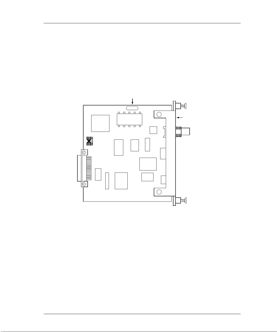
NETJet
Reference Numbers
It is important that you make a note of the printer server’s unique ethernet
address (known as the Media Access Control or MAC address) and its serial
number. The figure below shows the locations of these numbers.
Printer Server Installation 2-1
Serial Number
BCS1909
Ethernet
MAC Address
Faceplate
Figure 2-1: Location of Reference Numbers
Although the following information is clearly printed on the unit, we suggest
you enter the numbers here for later reference.
MAC Address: 00-00-C9- ____ ____-____ ____-____ ____
Serial Number: ____ ____ ____ ____ ____ ____ ____
Next, enter the default printer server name. This name begins with a three
digit prefix unique to the type of printer server. The remaining digits are
taken from the last six characters of the MAC address, without the dashes.
For example, the prefix for the NETJet is NJA. Combined with a MAC
address such as 00-00-C9-01-A0-6A, the default server name for this printer
server will be NJA01A06A.
Page 22

2-2 Chapter 2
The default printer server name is very important and is always used when
installing the printer server for the first time. Once a successful installation
has been accomplished, the default printer server name can be changed.
Default Server Name: NJA _____ _____ _____ _____ _____ _____
To determine the default printer name, enter the Emulex default printer server
name combined with the Emulex printer server port number. Port numbering
on the NETJet is as follows:
• #1 - Console terminal port
For example, NJA01A06A_1 is the NETJet console terminal port.
Default Printer Name: NJA____ ____ ____ ____ ____ ____ _ ____
Installation
The printer server may be installed in Hewlett-Packard MIO compliant
printers and plotters. Procedures vary by printer model, but will be similar to
these basic installation instructions.
NOTE: We suggest you use the default printer server name
when installing the printer server for the first time.
CAUTION: Printer power must be OFF or permanent damage
could result to both the printer or plotter and the
printer server.
1) Turn the AC power switch OFF on the printer.
2) Remove the AC power cord from the printer.
3) Remove any cables connected to the printer.
4) Expose the MIO slot.
Remove any interface board or faceplate from the MIO slot.
5) Remove the Emulex printer server from its anti-static bag.
6) Insert the Emulex printer server into the printer MIO slot.
Page 23
7) Gently press the board into position.
8) Tighten the two captive screws.
The captive screws are located on the face of the Emulex printer server.
Tightening these screws will secure the printer server to the printer.
LAN Connections & Cabling
The printer server may be connected to the network with one of these cables.
• Unshielded twisted-pair (UTP) with an RJ-45 connector
• Thinwire with BNC connector and BNC T-adapter
CAUTION: Do not connect network cables to both the
BNC and the UTP ports on the printer server
at the same time.
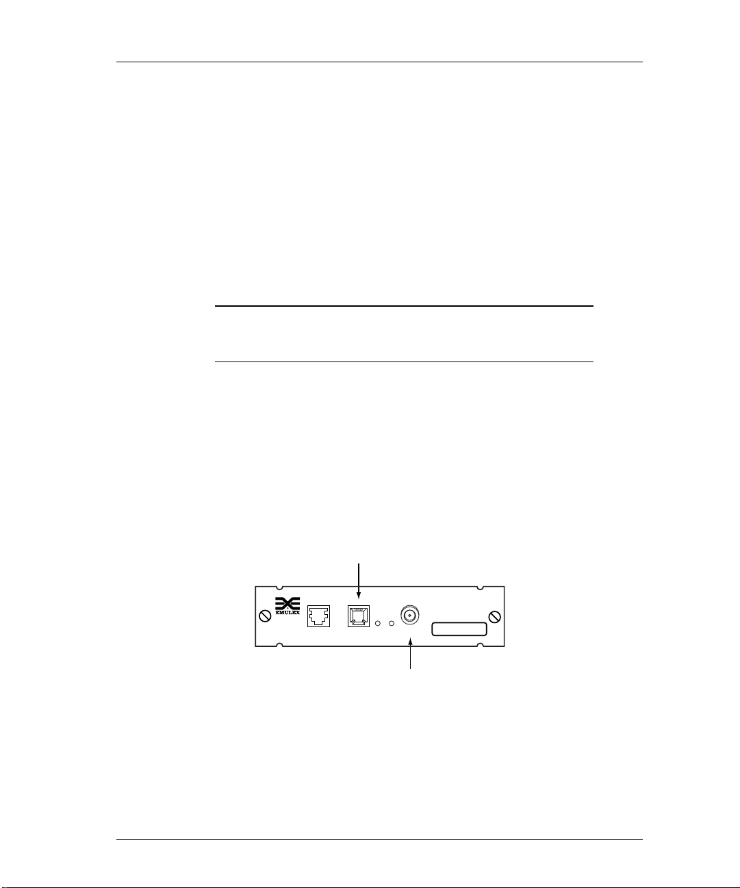
Unshielded Twisted-Pair Connection
1) Connect one end of the UPT cable to the printer server UTP port.
Printer Server Installation 2-3
See Appendix for UTP pinout details.
2) Connect the other end of the UTP cable to the network.
3) Do not connect anything to the printer server BNC port.
Twisted Pair
Connector
NETJet
MAC ADDRESS
CONSOLE UTP 1 2 BNC
Thin Wire
Connector
Figure 2-2: Printer Server LAN Connections
00-00-C9-01-A0-6A
Page 24
2-4 Chapter 2
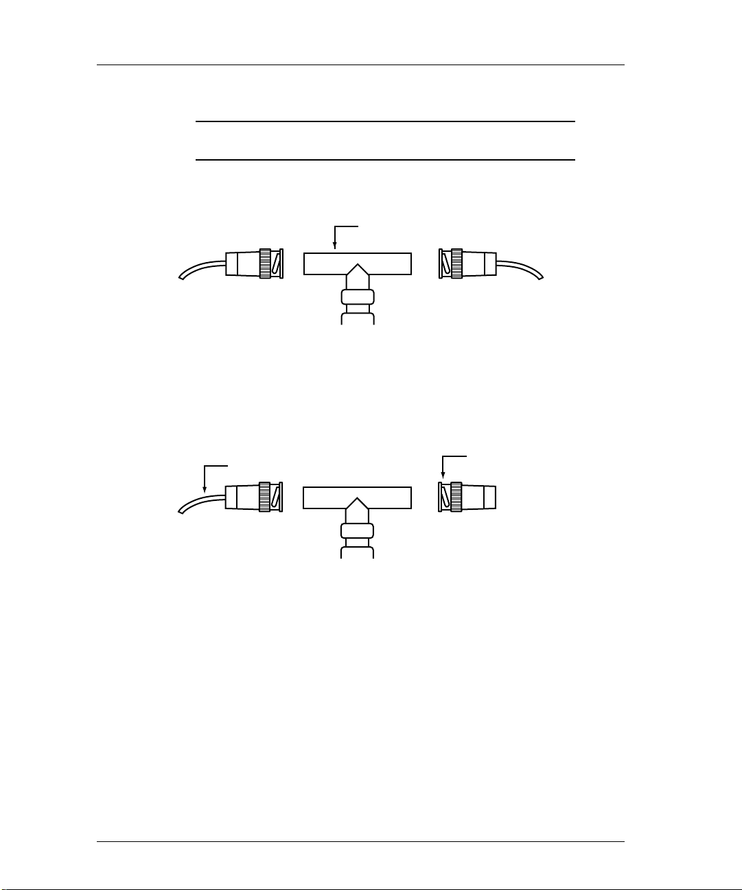
Thinwire BNC Connection
CAUTION: Do not break the ethernet connection while
1) If connecting to the middle of a cable segment, use a BNC T-adapter.
Figure 2-3: BNC T-Adapter Within a Segment
2) If connecting the printer server to the end of a cable segment, connect the
LAN cable to one side of the BNC T-adapter and a 50 ohm terminator to
the other side.
LAN is active.
BNC T-Adapter
Segment of Thinwire
50 Ohm Terminator
Figure 2-4: BNC T-Adapter With Terminator at End of Segment
3) Attach the BNC T-adapter and cable to the printer server BNC port.
4) Do not attach anything to the printer server UTP port.
Page 25
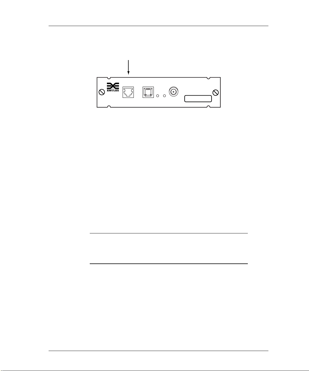
Peripheral Connection
Console/Serial Port
CONSOLE UTP 1 2 BNC
Printer Server Installation 2-5
NETJet
MAC ADDRESS
00-00-C9-01-A0-6A
Serial Port
Connect to the serial port with a null modem cable. The serial port provides
an RJ-12 connector and allows user to:
• Print to a serial printer or plotter.
• Monitor the printer server by connecting an ANSII compatible terminal or
• Input print jobs directly by connecting to a host system serial port (e.g. an
Figure 2-5: Peripheral Connection
a PC running an ANSII terminal emulation program.
The Emulex default port configuration is set for 9600 bps, 8 data bits, no
parity, 1 stop bit, DTE type, with softcopy emulation.
HP 3000).
NOTE: Serial cable between the printer server and the
peripheral device or console terminal should not
exceed 50 feet (15.24 meters). Connection can be
made through a null modem cable.
Page 26
2-6 Chapter 2
Power Up
1) Verify Emulex printer server is securely seated in printer slot.
2) Verify LAN connection to the printer server is secure.
3) Reattach AC power cord to printer.
4) Turn printer on.
Wait approximately 1 minute for the printer to perform self-tests. Tests
are complete when the printer’s LCD displays Ready or the Ready
indicator light illuminates.
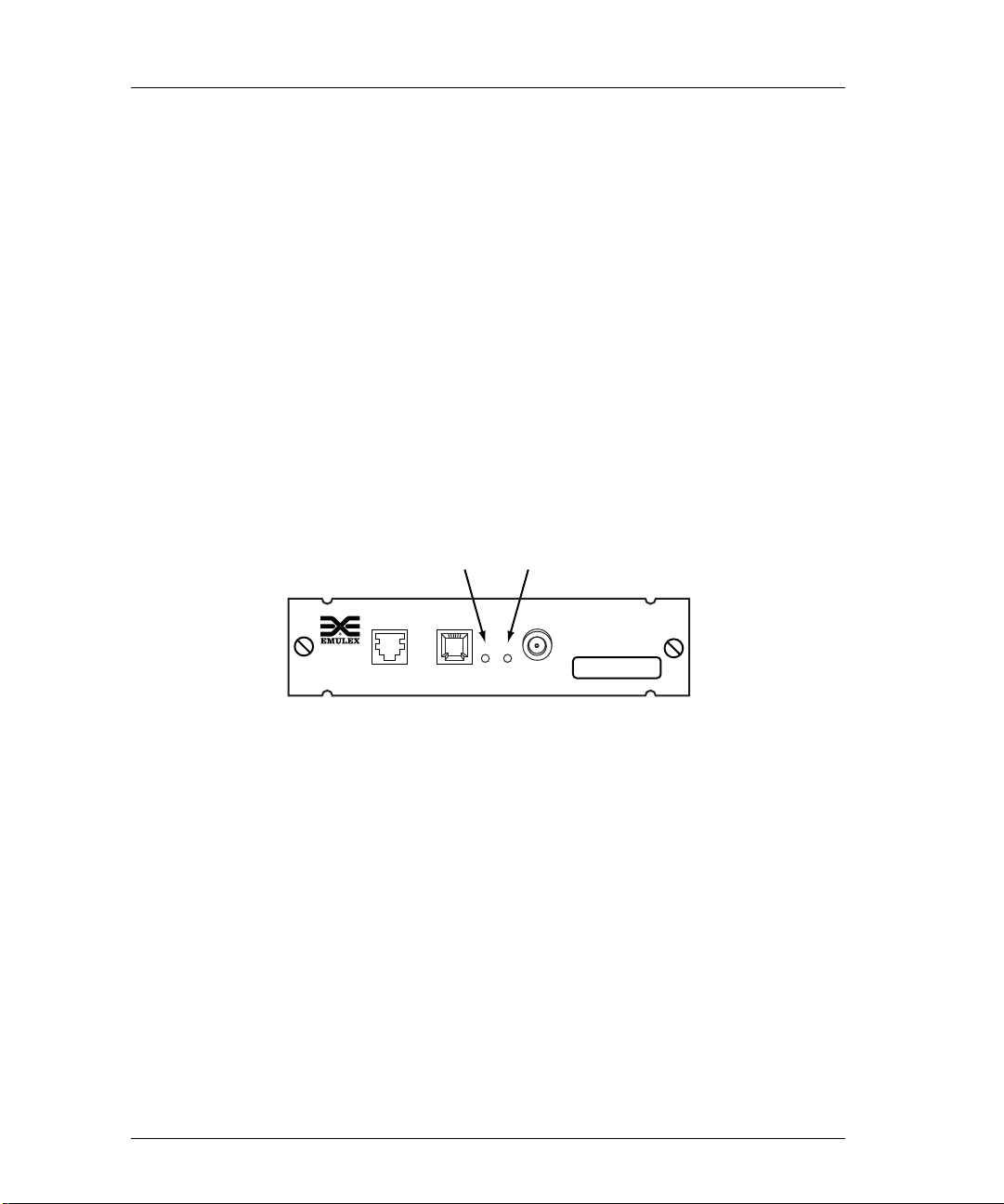
Display Lights (LEDs)
1) If the network is active, the yellow LAN LED-#2 will flash.
2) If the UTP connector is used, the green UTP LED-#1 will illuminate.
3) If the BNC connector is used, the green UTP LED-#1 will not illuminate.
UTP LED LAN LED
NETJet
MAC ADDRESS
CONSOLE UTP 1 2 BNC
Figure 2-6: Printer Server Display LEDs
00-00-C9-01-A0-6A
Page 27

Print Test Pagearameters
The test pageparameter printout is a useful tool that can be used to verify the
connection between the printer server and the printer. The test page contains
the following data:
reference when configuring the printer server. The print out contains
default and recently changed informationPrinter sServer nName
MAC Address
efault remote pPrinter nName Node Nname
DD
Hardware & fFirmware revisions NOS iInformation
SSoftware revision Network pProtocols
To print the test page, perform the following steps:
1) Verify printer has power and is On-Line.
2) Turn the printer OFF.
3) Disconnect the LAN cable.
4) Turn printer ON.
Printer Server Installation 2-7
5) Verify the printer is On-Line.
6) The printout will occur within 90 seconds.
If no printout occurs, make sure printer shows power ON, Ready and OnLine. Verify printer server installation and try printing test page again.
NOTE: If the printer is PCL or text only, the test printout
may contain PostScript commands.
Print Configuration Parameters
To obtain a printout of configuration parameters, enter this software
command:
Server>> show server config port port_num [ps]
>
port_num The output is directed to the specified port number.
ps Puts the output in PostScript format.
Page 28

2-8 Chapter 2
Reset to Factory Defaults
Before resetting to factory defaults, we recommend that you print out a
configuration page. Using the command described below will reset the
printer server to its factory defaults.
• The printer server will reset to factory defaults when power is cycled.
• The IP address and subnet mask are reset to NONE (000.000.000.000).
• Non-volatile memory is reset to factory defaults.
To reset to factory defaults:
1) Obtain privileged status.
2) Enter this command:
Server>> initialize [server] [delay delay_min]
>
[default]
delay Indicates reintialization will not take place until after a
delay_min Specifies the time before the server is stopped and
default Resets the server to factory defaults
specified period of time.
the initialization process begins. The default is 1
minute.
3) Cycle printer power.
Page 29

Printer Server Installation 2-9
Factory Default Configuration
Parameter Default Setting
Passwords
Printer server name
Printer services
• Remote printer names
• TCP port numbers
• lpd Service
LAT port names
lpd Queues
• ASCII files
• PostScript or binary files
Serial port configuration
system (privilege mode)
access (remote login)
NJAxxxxxx (xxxxxx are the last six
characters of the MAC Address)
NJAxxxxxx_1 (MIO port)
NJAxxxxxx_2 (serial port)
2501 (MIO port)
2502 (serial port)
MIO port only; TCP port 515
PORT_1 (MIO port)
PORT_2 (serial port)
TEXT
PASSTHRU
9600 bps, 8 data, 1 stop, no parity,
DTE type, softcopy emulation
Management Access
• Telnet port number
• RCF port number
• TES service name
23
2048
NJAxxxxxx (xxxxxx are last six
characters of the MAC address)
Page 30

2-10 Chapter 2
Printer Server Specifications
Parameter Range
Ethernet Compatibility
Physical Dimensions
Power Requirements
Temperature
Humidity
Agency Approval
IEEE802.3, IEEE802.2, Ethernet Type 2
10base2, Thinwire (BNC)
10baseT, Unshielded Twisted-Pair (UTP) (RJ45)
5 x 5.5 (12.7 x 13.9cm)
5VDC@ 1.0 Amp supplied by printer
Operating: 41° to 109.4° F (5° to 43° C)
Storage: -40° to 140° F (-40° to 60° C)
10% to 95% noncondensing
FCC Rules Class A; EN55022, CISPR22/85,
Class B; EN50082-1.
Page 31

Declaration of Conformity
This Declaration identifies the product, manufacturer’s name and address, and
applicable specifications recognized in the European Union
Printer Server Installation 2-11
.
DECLARATION OF CONFORMITY
Manufacturer: Emulex Corporation
declares under sole responsibility that the produc t:
Product Name: NETJet Printer Server
Model Number: NJ01B-NT+
to which this Declaration relates is in conformity with the following standards or
other documents:
Safety: IEC950:1991+A1,A2/EN60950 (1992)+ A1,A2
EMC:
following the provisions of the EMC Directive 89/336/EEC and Low Voltage Directive
73/23/EEC and carries the CE Marking accordingly.
October 20, 1995
Costa Mesa, CA
3535 Harbor Blvd.
Costa Mesa, CA 92626
USA
(Ethernet, multiport printer server)
EN55022 (1987)/CISPR-22 (1985), Class B
EN50082-1 (1992)
Paul Folino, President & CEO
European Contact: Emulex Europe Ltd. Telephone: 44-1734-772-929
Mulberry Business Park Fax: 44-1734-773-237
Fishponds Road
Wokingham, Berk s hi r e
RG41 2GY, England
Page 32

2-12 Chapter 2
What’s Next?
After successfully installing your Emulex printer server, you must configure
the network operating system (NOS). Refer to the following list.
Configure NOS
Choose one or more operating systems.
• Novell NetWare – page 3-1
• UNIX – page 4-1
• AppleTalk – page 5-1
• VAX/VMS-LAT – page 6-1
• DOS LAN Manager– page 7-1
• OS/2 LAN Server – page 8-1
• Windows NT 3.5 – page 9-1
Page 33

NETQue Pro2
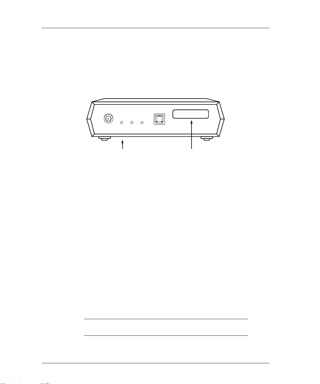
Reference Numbers
It is important that you make a note of the printer server’s unique ethernet
address (known as the Media Access Control or MAC address) and its serial
number. The figure below shows the locations of these numbers.
MAC Address
Printer Server Installation 2-13
MAC ADDRESS
00-00-C9-01-A0-6A
Serial Number
(bottom panel)
POWER
Figure 2-7: Location of Reference Numbers
Although the following information is clearly printed on the unit, we suggest
you write the numbers here for later reference.
Ethernet (MAC) address: 00-00-C9- ___ ___-___ ___-___ ___
Serial Number: ____ ____ ____ ____ ____ ____ ____
Next, enter the default printer server name. This name begins with a three
digit prefix unique to the type of printer server. The remaining digits are
taken from the last six characters of the MAC address, without the dashes.
For example, the prefix for the NETQue Pro2 is NP2. Combined with a
MAC address such as 00-00-C9-01-A0-6A, the default server name for this
printer server will be NP201A06A.
The default printer server name is very important and is always used when
installing the printer server for the first time. Once a successful installation
has been accomplished, the default printer server name can be changed.
Default Server Name: NP2 _____ _____ _____ _____ _____ _____
NOTE: Use the default printer server name when installing
the printer server for the first time.
Page 34

2-14 Chapter 2
To determine the default printer name, enter the Emulex default printer server
name combined with the Emulex printer server port number. Port numbering
on the NETQue Pro2 is as follows:
• #1 - Upper parallel port
• #2 - Lower parallel port
• #3 - Serial port
For example, NP201A06A_3 is the NETQue Pro2 serial port.
Default Printer Name: NP2 ____ ____ ____ ____ ____ ____ _ ____
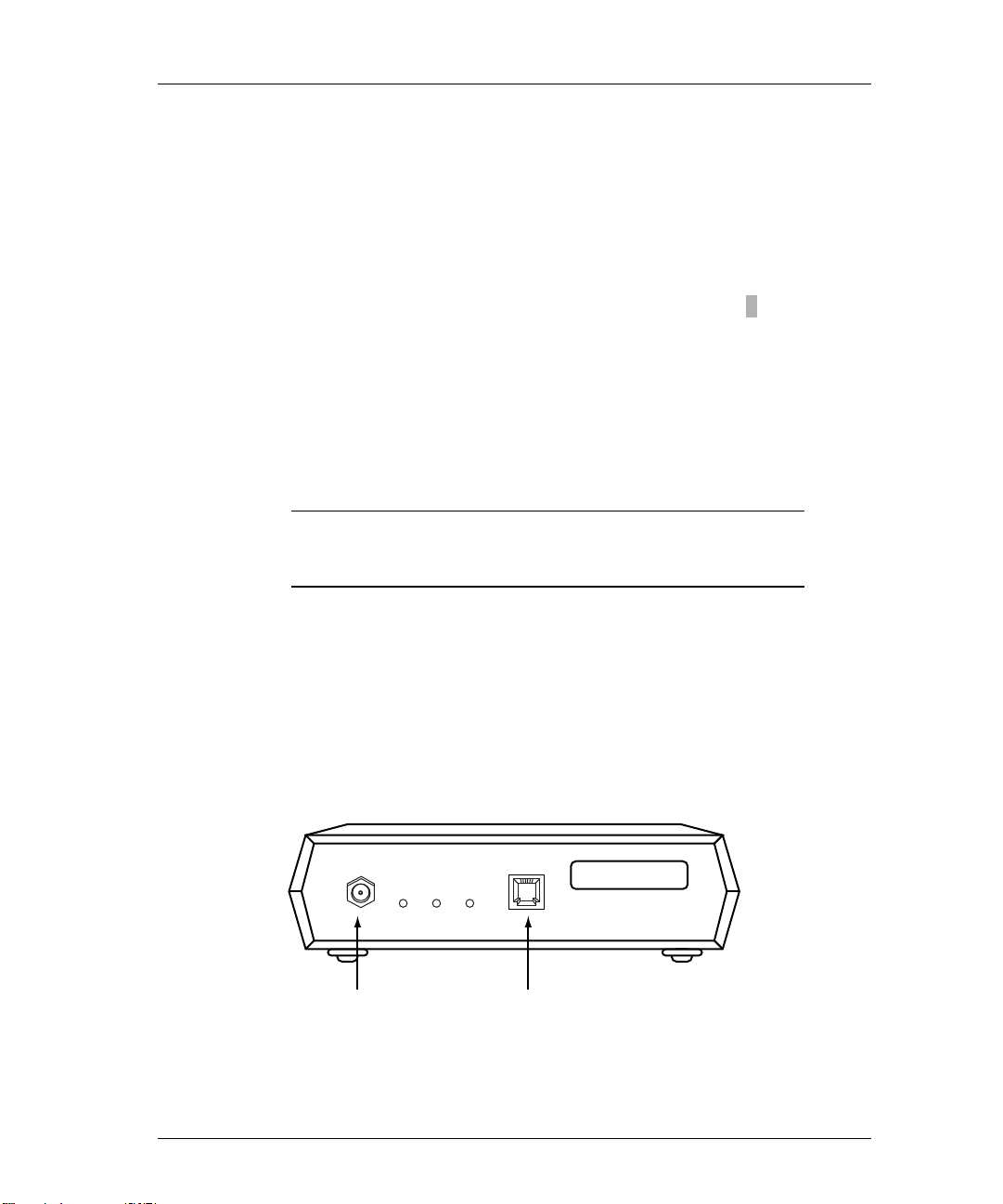
LAN Connections & Cabling
The printer server may be connected to the network with one of these cables.
• Unshielded twisted-pair (UTP) with an RJ-45 connector
• Thinwire with a BNC connector and BNC T-adapter
CAUTION: Do not connect network cables to both the BNC
and the UTP ports on the printer server at the
same time.
Unshielded Twisted-Pair Connection
1) Connect one end of the UTP cable to the printer server UTP port.
See Appendix for UTP pinout details.
2) Connect the other end of the UTP cable to the entwork.
3) Do not connect anything to the printer server BNC port.
MAC ADDRESS
00-00-C9-01-A0-6A
UTPBNC
Figure 2-8: Printer Server LAN Connections
POWER
Page 35

Thinwire BNC Connection
CAUTION: Do not break the ethernet connection while
1) If connecting to the middle of a cable segment, use a BNC T-adapter.
Figure 2-9: BNC T-Adapter Within a Segment
2) If connecting the printer server to the end of a cable segment, connect the
LAN cable to one side of the BNC T-adapter and a 50 ohm terminator to
the other side.
Printer Server Installation 2-15
LAN is active.
BNC T-Adapter
Segment of Thinwire
50 Ohm Terminator
Figure 2-10: BNC T-Adapter With Terminator at End of Segment
3) Attach the BNC T-adapter and cable to the printer server BNC port.
4) Do not attach anything to the printer server UTP port.
Page 36

2-16 Chapter 2
Peripheral Connections
Parallel Ports
The parallel ports provide female DB25 connectors and support the following
types of peripherals:
• A printer or plotter supporting a Centronics parallel port
• A printer or plotter supporting the bi-directional parallel interface
(IEEE 1284)
NOTE: The parallel cable between the printer server and
the printing device should not exceed 12 feet (3.65
meters).
Parallel 2
Serial Port
Connect to the serial port with a null modem cable. The serial port provides a
male DB9 connector and allows user to:
• Print to a serial printer or plotter.
• Monitor the printer server by connecting an ANSII compatible terminal or
• Input print jobs directly by connecting to a host system serial port (e.g. an
MAC ADDRESS
00-00-C9-01-A0-6A
Serial
Parallel 1
POWER
Figure 2-11: Peripheral Connections
a PC running an ANSII terminal emulation program.
The Emulex default port configuration is set for 9600 bps, 8 data bits, no
parity, 1 stop bit, DTE type, with softcopy emulation.
HP 3000).
Page 37

Power Up
1) Verify the LAN connection to the printer server is secure.
2) Verify all serial and parallel cable connections are secure.
3) Attach power cable to the printer server AC power receptacle and to an
Printer Server Installation 2-17
NOTE: Serial cable between the printer server and the
peripheral device or console terminal should not
exceed 50 feet (15.24 meters). Connection can be
made through a null modem cable.
accessible AC power outlet. The printer server will power up.
CAUTION: The AC power outlet must be accessible for
immediate removal of power.
Power
MAC ADDRESS
00-00-C9-01-A0-6A
POWER
Figure 2-12: Power Outlet
NOTE: If the printer server is being used outside the
United States where voltages may vary, it will
automatically adapt to the change of input voltages
when AC power is applied. Please refer to the
power cord selection card supplied with the printer
server for appropriate power cord configuration.
Page 38

2-18 Chapter 2
Display Lights (LEDs)
1) When the printer server is powered up, the green POWER LED and the
yellow PORT LED will illuminate.
2) Wait 15 to 20 seconds after power is applied.
During this time, the printer server is performing its self-test.
3) When the printer server passes its self-tests, the yellow PORT LED will
go out. If the printer server does not pass, the yellow PORT LED will
flash alternately with the green POWER LED.
4) If the network is active, the yellow LAN LED will flash with network
activity.
5) If the UTP connector is used, the green LINK LED will illuminate.
6) If the BNC connector is used, the green LINK LED will not illuminate.
7) If any of the connected peripheral ports is active, the yellow PORT LED
will flash showing port activity.
Status
Button
Figure 2-13: Printer Server Display LEDs
Power Link LAN Port
Page 39

Print Test Page
The test page is a helpful tool that can be used to verify the connection
between the printer server and the printer. The test page contains the
following data:
This procedure assumes that at least one printer is connected.
1) Verify the Emulex printer server has power.
2) Verify printer has power and is On-Line.
Printer Server Installation 2-19
reference when configuring the printer server. The print out contains
default and recently changed informationPrinter sServer nName
MAC Address
efault remote pPrinter nName Node Nname
DD
Hardware & fFirmware revisions NOS iInformation
SSoftware revision Network pProtocols
3) Disconnect power to the printer server.
4) Disconnect LAN cable.
5) Reconnect power to printer server.
6) The printout will occur within 90 seconds.
If no printout occurs, verify all connections and make sure printer shows
power ON, Ready and On-Line.
NOTE: If the printer is PCL or text only, the test printout
may contain PostScript commands.
Page 40

2-20 Chapter 2
Print Configuration Parameters
Starting with software release 4.15, two methods can be used for printing
configuration parameters. The first method uses the status button, and the
second employs a software command.
Using Status Button
This procedure assumes that at least one printer is attached to the printer
server.
NOTE: If the printer is PCL or text only, the test printout
may contain Postscript commands.
1) Verify printer server has power.
2) Verify printer has power and is ON-LINE.
3) Momentarily depress the printer server status button.
If two printers are connected to the parallel ports, the printer server will
utilize the first available printer. If both printers are active with print
jobs, the status button is ignored.
Using Software Command
To obtain a printout of configuration parameters, enter this software
command:
Server>> show server config port port_num [ps]
>
port_num The output is directed to the specified port number.
ps Puts the output in PostScript format.
Page 41

Reset to Factory Defaults
Before resetting to factory defaults, we recommend that you print out a
configuration page. Two methods can be used to reset the printer server to its
factory defaults.
• Using the status button
− The printer server will reset to factory defaults immediately.
− IP address and subnet mask are reset to NONE (000.000.000.000).
− Non-volatile memory is reset to factory defaults.
• Using a software command
− The printer server will reset to factory defaults when power is cycled.
− IP address and subnet mask are reset to NONE (000.000.000.000).
− Non-volatile memory is reset to factory defaults.
Reset Using Status Button
1) Remove AC power cord from the printer server.
Printer Server Installation 2-21
2) Depress status button and hold.
3) Reconnect AC power cord to printer server, then release status button.
Reset Using Software Commands
1) Obtain privileged status.
2) Enter this command:
Server>> initialize server delay delay_min default
>
delay Indicates reintialization will not take place until after a
delay_min Specifies the time before the server is stopped and
default Resets the server to factory defaults
specified period of time.
the initialization process begins. The default is 1
minute.
Page 42

2-22 Chapter 2
Factory Default Configuration
Parameter Default Setting
Passwords
Printer server name
Printer services
Remote printer names
TCP port numbers
lpd service
LAT port names
lpd Queues
ASCII files
PostScript or binary files
system (privilege mode)
access (remote login)
NP2xxxxxx (xxxxxx are the last six
characters of the MAC Address)
NP2xxxxxx_1 (parallel port 1)
NP2xxxxxx_2 (parallel port 2)
NP2xxxxxx_3 (serial port)
2501 (parallel port 1)
2502 (parallel port 2)
2503 (serial port)
Parallel ports only; TCP port 515
PORT_1 (parallel port 1)
PORT_2 (parallel port 2)
PORT_3 (serial port)
TEXT
PASSTHRU
Serial port configuration
Management Access
Telnet port number
RCF port number
TES service name
9600 bps, 8 data, 1 stop, no parity,
DTE type, softcopy emulation
23
2048
NP2xxxxxx (xxxxxx are the last six
characters of MAC address)
Page 43

Printer Server Specifications
Parameter Range
Printer Server Installation 2-23
Ethernet Compatibility
Physical Dimensions
Power Requirements
Temperature
Humidity
Agency Approval
IEEE802.3, IEEE802.2, Ethernet Type 2
10base2, Thinwire (BNC)
10baseT, Unshielded Twisted-Pair (UTP) (RJ45)
5 x 6.5 x 1.0 inches (12.7 x 16.5 x 2.54 cm)
100 - 260 VAC, 47 - 63 Hz, 0.1 Amp
Operating: 41° to 109.4° F (5° to 43° C)
Storage: -40° to 140° F (-40° to 60° C)
10% to 95% noncondensing
FCC Class A; UL listed to UL 1950; TUV Certified
to EN60950; EN55022, CISPR 22/85 Class A;
CUL Listed to CSA22.2, No.950; EN50082-1.
Page 44

2-24 Chapter 2
Declaration of Conformity
This equipment complies with CISPR22/EN55022 Class A.
WARNING: This is a class A product. In a domestic environment, this
product may cause radio interference requiring the user to
take adequate measures.
This Declaration identifies the product, manufacturer’s name and address, and
applicable specifications recognized in the European Union
.
DECLARATION OF CONFORMITY
Manufacturer:
declares under sole responsibility that the product:
Product Name: NETQue Pro2 Printer Server
Model Number: NP02
to which this Declaration relates is in conformity with the following standards or
other documents:
Safety:
EMC:
following the provisions of the EMC Directive 89/336/EEC and Low Voltage Directive
73/23/EEC and carries the CE Marking accordingly.
October 20, 1995
Costa Mesa, CA
European Contact: Emulex Europe Ltd. Telephone: 44-1734-772-929
Mulberry Business Park Fax: 44-1734-773-237
Fishponds Road
Wokingham, Berkshire
RG41 2GY, England
Emulex Corporation
3535 Harbor Blvd.
Costa Mesa, CA 92626
USA
(Ethernet, multiport printer server)
IEC950:1991+A1,A2/EN60950 (1992)+ A1,A2
TUV Rheinland, Certificate No. S9577208
EN55022 (1987)/CISPR-22 (1985), Class A
EN50082-1 (1992)
Paul Folino, President & CEO
Page 45

What’s Next?
After successfully installing your Emulex printer server, you must configure
the network operating system (NOS). Refer to the following list.
Configure NOS
Choose one or more operating systems.
• Novell NetWare – page 3-1
• UNIX – page 4-1
• AppleTalk – page 5-1
• VAX/VMS-LAT – page 6-1
• DOS LAN Manager– page 7-1
• OS/2 LAN Server – page 8-1
• Windows NT 3.5 – page 9-1
Printer Server Installation 2-25
Page 46
2-26 Chapter 2
NETQue
Reference Numbers
It is important that you make a note of the printer server’s unique ethernet
address (known as the Media Access Control or MAC address) and its serial
number. The figure below shows the locations of these numbers.
MAC ADDRESS
00-00-C9-01-A0-6A
Serial Number
(bottom panel)
Figure 2-14: Location of Reference Numbers
Mac Address
Although the following information is clearly printed on the unit, we suggest
you enter the numbers here for later reference.
Ethernet (MAC) Address: 00-00-C9- ____ ____-____ ____-____ ____
Serial Number: ____ ____ ____ ____ ____ ____ ____
Next, enter the default printer server name. This name begins with a three
digit prefix unique to the type of printer server. The remaining digits are
taken from the last six characters of the MAC address, without the dashes.
For example, the prefix for the NETQue is NQA. Combined with a MAC
address such as 00-00-C9-00-02-E6, the default server name for the printer
server will be NQA0002E6.
The default printer server name is very important and is always used when
installing the printer server for the first time. Once a successful installation
has been accomplished, the default printer server name can be changed.
Default Server Name: NQA _____ _____ _____ _____ _____ _____
NOTE: We suggest you use the default printer server name
when installing the printer server for the first time.
Page 47
To determine the default printer name, enter the Emulex default printer server
name combined with the Emulex printer server port number. Port numbering
on the NETQue is as follows:
• #1 - Parallel port
• #2 - Serial port
For example, NQA0002E6_2 is the NETQue serial port.
Default Printer Name: NQA ____ ____ ____ ____ ____ ____ _ ____
LAN Connections & Cabling
The printer server may be connected to the network with one of these cables.
• Unshielded twisted-pair (UTP) with an RJ-45 connector
• Thinwire with a BNC connector and BNC T-adapter
CAUTION: Do not connect network cables to both the
Printer Server Installation 2-27
BNC and the UTP ports on the printer server
at the same time.
Unshielded Twisted-Pair UTP Connection
1) Connect one end of the UTP cable to the printer server UTP port.
See Appendix for UTP pinout details.
2) Connect the other end of the UTP cable to the network.
3) Do not attach anything to the printer server BNC port.
Thinwire
Connector
Figure 2-15: Printer Server LAN Connections
ETHERNET ADDRESS
00-00-C9-01-A0-6A
Twisted Pair
Connector
Page 48

2-28 Chapter 2
Thinwire BNC Connection
CAUTION: Do not break the ethernet connection while
1) If connecting to the middle of a cable segment, use a BNC T-adapter.
LAN is active.
BNC T-Adapter
Figure 2-16: BNC T-Adapter Within a Segment
2) If connecting the printer server to the end of a cable segment, connect the
LAN cable to one side of the BNC T-adapter and a 50 ohm terminator to
the other side.
Segment of Thinwire
Figure 2-17: BNC T-Adapter With Terminator at End of Segment
50 Ohm Terminator
3) Attach the BNC T-adapter and cable to the printer server BNC port.
4) Do not attach anything to the printer server UTP port.
Page 49

Peripheral Connections
Parallel Port
The parallel port provides a female DB25 connector and supports the
following types of peripherals:
• A printer or plotter supporting a Centronics parallel port
• A printer or plotter supporting the bi-directional parallel interface
(IEEE 1284)
NOTE: The parallel cable between the printer server and
Printer Server Installation 2-29
the printing device should not exceed 12 feet (3.65
meters).
Serial Port
Connect to the serial port with a null modem cable. The serial port provides a
male DB9 connector and allows user to:
• Print to a serial printer or plotter.
• Monitor the printer server by connecting an ANSII compatible terminal or
• Input print jobs directly by connecting to a host system serial port (e.g. an
Parallel PortSerial Port
Figure 2-18: Peripheral Connections
a PC running an ANSII terminal emulation program.
The Emulex default port configuration is set for 9600 bps, 8 data bits, no
parity, 1 stop bit, DTE type, with softcopy emulation.
HP 3000).
Page 50

2-30 Chapter 2
Power Up
1) Verify the LAN connection to the printer server is secure.
2) Verify all serial and parallel cable connections are secure.
3) Attach the modular power supply cable to the printer server jack labeled
+5 VDC.
4) Plug the power supply module into an AC power outlet.
The printer server will power up and go through a self-test.
NOTE: Serial cable between the printer server and the
peripheral device or console terminal should not
exceed 50 feet (15.24 meters). Connection can be
made through a null modem cable.
CAUTION: The AC power outlet must be accessible for
immediate removal of power.
Power
Connector
Figure 2-19: Power Outlet
NOTE: Please refer to the Optional Power Supply
Specification section if the printer server is being
used outside the United States where voltages may
vary.
Page 51

Display Lights (LEDs)
1) When the printer server is powered up, the green POWER LED will
illuminate.
2) Wait 15 to 20 seconds after power is applied.
During this period, the printer server is performing its self-test.
3) If the network is active, the printer server yellow LAN LED will flash
with network activity.
4) If the UTP connector is used, the green LINK LED will illuminate.
5) If the BNC connector is used, the green LINK LED will not illuminate.
Printer Server Installation 2-31
ETHERNET ADDRESS
00-00-C9-01-A0-6A
Power
(green)
Figure 2-20: Printer Server Display LEDs
LAN
(yellow)
UTP
(green)
Page 52

2-32 Chapter 2
Print Test Page
The test page is a helpful tool that can be used to verify the connection
between the printer server and the printer. The test page contains the
following data:
Printer
sServer nName MAC Address
DDefault remote pPrinter nName Node Nname
Hardware & fFirmware revisions NOS iInformation
SSoftware revision Network pProtocols
To print the test page, perform the following steps:
1) Verify the Emulex printer server has power.
2) Verify printer has power and is On-Line.
3) Disconnect power to the printer server.
4) Disconnect LAN cable.
5) Reconnect power to printer server.
6) The printout will occur within 90 seconds.
If no printout occurs, verify all connections and make sure printer shows
power ON, Ready and On-Line.
NOTE: If the printer is PCL or text only, the test printout
may contain PostScript commands.
Print Configuration Parameters
To obtain a printout of configuration parameters, enter this command:
Server>> show server config port port_number [ps]
>
port_number Enter the printer server port number.
ps Puts the output in PostScript format.
Page 53

Reset to Factory Defaults
Before resetting to factory defaults, we recommend that you print out a
configuration page. Using the command described below will reset the
printer server to its factory defaults.
• The printer server will reset to factory defaults when power is cycled.
• The IP address and subnet mask are reset to NONE (000.000.000.000).
• Non-volatile memory is reset to factory defaults.
To reset to factory defaults:
1) Obtain privileged status.
2) Enter this command:
Server>> initialize [server] [delay delay_min]
>
[default]
delay Indicates reintialization will not take place until after a
delay_min Specifies the time before the server is stopped and
default Resets the server to factory defaults
Printer Server Installation 2-33
specified period of time.
the initialization process begins. The default is 1
minute.
3) Cycle printer power.
Page 54

2-34 Chapter 2
Factory Default Configuration
Parameter Default Setting
Passwords
Printer server name
Printer services
Remote printer names
TCP port numbers
lpd service
LAT port names
lpd Queues
ASCII files
PostScript or binary files
Serial port configuration
system (privilege mode)
access (remote login)
NQAxxxxxx (xxxxxx are the last six characters
of the MAC Address)
NQAxxxxxx_1 (parallel port)
NQAxxxxxx_2 (serial port)
2501 (parallel port)
2502 (serial port)
parallel port only; TCP port 515
PORT_1 (parallel port)
PORT_2 (serial port)
TEXT
PASSTHRU
9600 bps, 8 data, 1 stop, no parity, DTE type,
softcopy emulation
Management Access
Telnet port number
RCF port number
TES service name
23
2048
NQAxxxxxx (xxxxxx are the last six characters
of MAC address)
Page 55

Printer Server Installation 2-35
Printer Server Specifications
Parameter Range
Ethernet Compatibility
Physical Dimensions
Power Requirements
Temperature
Humidity
Agency Approval
IEEE 802.3, Ethernet Type 2
10base2, Thinwire (BNC)
10baseT, Unshielded Twisted-Pair (UTP) (RJ45)
5.5 x 6.75 x 1.75 inches (14.0 x 17.1 x 4.4 cm)
+ 5 VDC (5% variance) @ 1 Amp minimum
Operating: 41° to 109.4° F (5° to 43°C)
Storage: -40° to 140° F (-40° to 60°C)
10% to 95% noncondensing
FCC Class A; UL Listed to UL 1950; TUV Certified
to EN60950; EN55022, CISPR22/85,Class A
(Class B For european models); CUL Listed to
CSA22.2, No.950; EN50082-1.
Page 56

2-36 Chapter 2
Optional Power Supply Specifications
Customers providing their own power supply will need to meet these
specifications. This will prevent damage to the printer server and ensure
reliable operation.
CAUTION: For European installations, compliance with
the EMC Directive 89/336/EEC requires the
use of Emulex power supply accessories.
Parameter Range
Output
Connector
Polarity
+ 5 VDC +
2.5 mm pin, 5.5 mm ID, 12.0 mm shaft length
Center positive
5% @ 1 Amp minimum
One of the following equipment or installation conditions is required for UL
approval:
Either:
• Connect the equipment to a +5 VDC power source that is electrically
isolated from the AC source. The +5 VDC source is to be reliably
connected to earth ground.
Or
• Connect the equipment to a +5 VDC SELV source.
Emulex offers the following power supply accessories:
Universal: 90 - 260 VAC, 50/60Hz input. Requires user supplied
•
detachable input power cord to match local power outlet configuration.
Conforms to CSA, UL and TUV or VDE requirements.
VDE: 230VAC, 50HZ input. Conforms to VDE or TUV requirements.
•
Australian: 240 VAC, 50Hz input. Conforms to SAA requirements.
•
• United Kingdom: 240 VAC, 50 Hz input. Plug conforms to EN60950
requirements.
Page 57

Declaration of Conformity
N
This Declaration identifies the product, manufacturer’s name and address, and
applicable specifications recognized in the European Union
Printer Server Installation 2-37
.
DECLARATION OF CONFORMITY
Manufacturer: Emulex Corporation
declares under sole responsibility that the product:
Product Name: NETQue Printer Server
Model Number: NQ0U-NT+, NQ0V-NT+, NQGB-NT+
including Accessories: ER2011809-00 (Mfg. Part Number AD051ARB-7)
(power supplies) ER2011810-00 (Mfg. Part Number LZUSD02001)
to which this Declaration relates is in conformity with the following standards or
other documents:
Safety:
EMC: EN55022 (1987)/CISPR-22 (1985), Class B
following the provisions of the EMC Directive 89/336/EEC and Low Voltage Directive
73/23/EEC and carries the CE Marking accordingly.
ovember 17, 1995
Costa Mesa, CA
European Contact: Emulex Europe Ltd. Telephone: 44-1734-772-929
Mulberry Business Park Fax: 44-1734-773-237
Fishponds Road
Wokingham, Berkshire
RG41 2GY, England
3535 Harbor Blvd.
Costa Mesa, CA 92626
USA
(Ethernet, multiport printer server)
ER2011812-00 (Mfg. Part Number AD051ARUK-7)
IEC950:1991+A1,A2/EN60950 (1992)+ A1,A2
TUV Rheinland, Certificate No. S9371375
EN50082-1 (1992)
Paul Folino, President & CEO
Page 58

2-38 Chapter 2
What’s Next?
After successfully installing your Emulex printer server, you must configure
the network operating system (NOS). Refer to the following list.
Configure NOS
Choose one or more operating systems.
• Novell NetWare – page 3-1
• UNIX – page 4-1
• AppleTalk – page 5-1
• VAX/VMS-LAT – page 6-1
• DOS LAN Manager– page 7-1
• OS/2 LAN Server – page 8-1
• Windows NT 3.5 – page 9-1
Page 59

NETQue Token Ring
Reference Numbers
It is important that you make a note of the printer server’s unique ethernet
address (known as the Media Access Control or MAC address) and its serial
number. The figure below shows the locations of these numbers.
PWR PA NA CONFIGURATION STP UTP
MAC Address
00-00-C9-01-A0-6A
Printer Server Installation 2-39
Serial Number
(Bottom Panel)
Figure 2-21: Location of Reference Numbers
MAC
Address
Although the following information is clearly printed on the unit, we suggest
you write the numbers here for later reference.
MAC Address: 00-00-93-_____ _____-_____ _____-_____ _____
Serial Number: ____ ____ ____ ____ ____ ____ ____
Next, enter the default printer server name. This name begins with a three
digit prefix unique to the type of printer server. The remaining digits are
taken from the last six characters of the MAC address, without the dashes.
For example, the prefix for the NETQue Token Ring is NQT. Combined
with a MAC address such as 00-00-93-01-A0-6A, the default server name for
this printer server will be NQT01A06A.
The default printer server name is very important and is always used when
installing the printer server for the first time. Once a successful installation
has been accomplished, the default printer server name can be changed.
Default Server Name: NQT_____ _____ _____ _____ _____ _____
Page 60

2-40 Chapter 2
To determine the default printer name, enter the Emulex default printer server
name combined with the Emulex printer server port number. Port numbering
on the NETQue Token Ring is as follows:
• #1 - Parallel port
• #2 - Serial port
For example, NQT01A06A_2 is the NETQue Token Ring serial port.
Default Printer Name: NQT____ ____ ____ ____ ____ ____ _ ____
Switch Settings
A four position switch is located on the network side of the printer server.
The functions of each are shown below. UP indicates a switch is ON and
DOWN shows the switch is OFF.
NOTE: We suggest you use the default printer server name
when installing the printer server for the first time.
Position 1
Reset to Factory Defaults
ON = Reset to Factory Default
OFF = Use for Normal Operation
O
N
Position 2
Position 3
Position 4
Token Ring Speed
ON = 4 Mbits/sec
OFF = 16 Mbits/sec
Parallel Port Type
ON = Bi-directional
OFF = Centronics
Reserved for Future Use
Figure 2-22: Switch Settings
Page 61
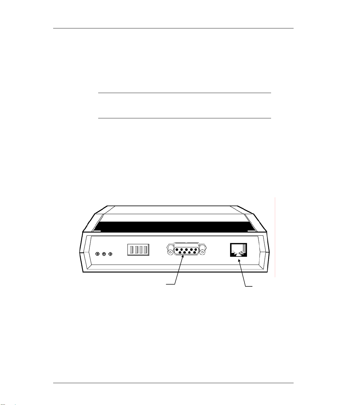
LAN Connections & Cabling
The printer server may be connected to the network with one of these cables.
• Unshielded twisted-pair (UTP) with an RJ-45 connector
• Shielded Twisted-pair (STP) with a DB9 connector
CAUTION: Do not connect network cables to both the UTP
and the STP ports on the printer server at the
same time.
Unshielded Twisted-Pair UTP Connection
1) Connect one end of the UTP cable to the printer server UTP port.
See Appendix for UTP pinout details.
2) Connect the other end of the UTP cable to the Token Ring network.
3) Do not connect anything to the printer server STP port.
Printer Server Installation 2-41
PWR PA NA CONFIGURATION STP UTP
STP Port
Figure 2-23: Printer Server LAN Connections
UTP Port
Page 62

2-42 Chapter 2
Shielded Twisted-Pair STP Connection
1) Connect one end of the STP cable to the printer server STP port.
See appendix for STP pinout details.
2) Connect the other end of the STP cable to the Token Ring network.
3) Do not connect anything to the printer server UTP port.
Peripheral Connections
Parallel Port
The parallel port provides a female DB25 connector and supports the
following types of peripherals:
• A printer or plotter supporting a Centronics parallel port
• A printer or plotter supporting the bi-directional parallel interface
(IEEE 1284)
NOTE: The parallel cable between the printer server and
the printing device should not exceed 12 feet (3.65
meters).
Figure 2-24: Peripheral Connections
Page 63

Serial Port
Connect to the serial port with a null modem cable. The serial port provides a
male DB9 connector and allows user to:
• Print to a serial printer or plotter.
• Monitor the printer server by connecting an ANSII compatible terminal or
• Input print jobs directly by connecting to a host system serial port (e.g. an
Power Up
Printer Server Installation 2-43
a PC running an ANSII terminal emulation program.
The Emulex default port configuration is set for 9600 bps, 8 data bits, no
parity, 1 stop bit, DTE type, with softcopy emulation.
HP 3000).
NOTE: Serial cable between the printer server and the
peripheral device or console terminal should not
exceed 50 feet (15.24 meters). Connection can be
made through a null modem cable.
CAUTION: The AC power outlet must be accessible for
immediate removal of power
1) Verify all switch settings are correct.
2) Verify the Token Ring LAN connection to the printer server is secure.
3) Verify all serial and parallel cable connections are secure.
4) Attach the modular power supply cable to the printer server jack labeled
+5 VDC.
Page 64

2-44 Chapter 2
5) Plug the power supply transformer into an AC power outlet.
The printer server will power up and go through a self-test.
Figure 2-25: Power Outlet
NOTE: Please refer to the Optional Power Supply
Specification section if the printer server is being
used outside the United States where voltages may
vary.
Power Outlet
Page 65

Display Lights (LEDs)
N
1) When the printer server is powered up, the green POWER LED will
illuminate.
2) Wait 15 to 20 seconds after power is applied.
During this period, the printer server is performing its self test.
3) If the network is active, the green NA LED will flash with network
activity.
4) If any of the connected peripheral ports is active, the yellow PA LED will
flash showing port activity.
PWR PA NA CONFIGURATION STP UTP
Printer Server Installation 2-45
Power
LED
Printer
Activity or PA
etwork Activity
or NA LED
Figure 2-26: Display LED’s
Page 66

2-46 Chapter 2
Print Test Pagearameters
The test page is a helpful tool that can be used to verify the connection
between the printer server and the printer. The test page contains the
following data:
reference when configuring the printer server. The print out contains
default and recently changed informationPrinter sServer nName
MAC Address
efault remote pPrinter nName Node Nname
DD
Hardware & fFirmware revisions NOS iInformation
SSoftware revision Network pProtocols
To print the test page, perform the following steps:
1) Verify the Emulex printer server has power.
2) Verify printer has power and is On-Line.
3) Disconnect power cord to the printer server.
4) Disconnect LAN cable.
5) Reconnect power cord to printer server.
6) The printout will occur within 90 seconds.
If no printout occurs, verify all connections and make sure printer shows
power ON, Ready and On-Line.
NOTE: If the printer is PCL or text only, the test printout
may contain PostScript commands.
Print Configuration Parameters
To obtain a printout of configuration parameters, enter this software
command:
Server>> show server config port port_number [ps]
>
port_number The output is directed to the specified port number.
ps Puts the output in PostScript format.
Page 67

Reset to Factory Defaults
Before resetting to factory defaults, we recommend that you print out a
configuration page. Two methods can be used to reset the printer server to its
factory defaults.
• Using switch settings
− The printer server will reset to factory defaults immediately.
− IP address and subnet mask are reset to NONE.
− Non-volatile memory and RAM are erased.
• Using a software command
− The printer server will reset to factory defaults when power is cycled.
− IP address and subnet mask are reset to NONE.
− Non-volatile memory and RAM are erased.
Reset Using Switch Settings
If necessary, review the information at the beginning of this chapter on the
function of each switch. To reset to factory defaults, follow these steps:
Printer Server Installation 2-47
1) Remove AC power cord from the printer server.
2) Move switch #1 to the ON position.
3) Reconnect AC power cord to printer server.
4) Move switch #1 to the OFF position.
The printer server will perform its self-test, load operational software, and
reset to factory defaults.
Page 68

2-48 Chapter 2
Reset Using Software Command
1) Obtain privileged status.
2) Enter this command:
Server>> initialize server delay delay_min default
>
delay Indicates reintialization will not take place until after a
delay_min Specifies the time before the server is stopped and
default Resets the server to factory defaults
specified period of time.
the initialization process begins. The default is 1
minute.
Page 69

Printer Server Installation 2-49
Factory Default Configuration
Parameter Default Setting
Passwords
Printer server name
Printer services
• Remote printer names
• TCP port numbers
• lpd Service
lpd Queues
• ASCII data
• PostScript or binary files
Serial port configuration
Management Access
system (privilege mode)
access (remote login)
NQTxxxxxx (xxxxxx are the last six
characters of the MAC Address)
NQTxxxxxx_1 (parallel port)
NQTxxxxxx_2 (serial port)
2501 (parallel port)
2502 (serial port)
Parallel port only; TCP port 515
These may not be renamed:
TEXT
PASSTHRU
9600 bps, 8 data, 1 stop, no parity,
DTE type, sofcopy emulation
• Telnet port number
• RCF port number
• TES service name
23
2048
NQTxxxxxx (xxxxxx are the last six
characters of the MAC address)
Page 70

2-50 Chapter 2
Printer Server Specifications
Parameter Range
Ethernet Compatibility
Physical Dimensions
Power Requirements
Temperature
Humidity
Agency Approval
IEEE 802.5
IBM Token Ring
Unshielded Twisted-Pair (UTP) RJ45
Shielded Twisted-Pair (STP) DB9
5.5 x 6.75 x 1.75
5VDC +
Operating: 41° to 109.4° F (5° to 43° C)
Storage: -40° to 140° F (-40° to 60° C)
10% to 90% noncondensing
FCC Class A; UL Listed to UL 1950; TUV
Certified to EN60950; CUL Listed to CSA22.2,
No.950; EN55022, CISPR22/85, Class A;
EN50082-1.
5% @ 1A
Page 71

Optional Power Supply Specifications
Customers providing their own power supply will need to meet these
specifications. This will prevent damage to the printer server and ensure
reliable operation.
CAUTION: For European installations, compliance with
the EMC Directive 89/336/EEC requires the
use of Emulex power supply accessories.
Parameter Range
Printer Server Installation 2-51
Output
Connector
Polarity
+ 5VDC +
2.5 mm pin, 5.5 mm ID, 12.0 mm shaft length
Center positive
5% @ 1 Amp minimum
One of the following equipment or installation conditions is required for UL
approval:
Either:
• Connect the equipment to a +5 VDC power source that is electrically
isolated from the AC source. The +5 VDC source is to be reliably
connected to earth ground.
Or:
• Connect the equipment to a +5 VDC SELV source.
Emulex offers the following power supply accessories:
Universal: 90 - 260 VAC, 50/60Hz input. Requires user supplied
•
detachable input power cord to match local power outlet configuration.
Conforms to CSA, UL and TUV or VDE requirements.
VDE: 230VAC, 50Hz input. Conforms to VDE or TUV requirements.
•
Australian: 240 VAC, 50Hz input. Conforms to SAA requirements.
•
United Kingdom: 240 VAC, 50 Hz input. Plug conforms to EN60950
•
requirements.
Page 72

2-52 Chapter 2
N
Declaration of Conformity
This equipment complies with CISPR22/EN55022 Class A.
WARNING: This is a class A product. In a domestic environment, this
product may cause radio interference requiring the user to
take adequate measures.
This Declaration identifies the product, manufacturer’s name and address, and
applicable specifications recognized in the European Union
.
DECLARATION OF CONFORMITY
Manufacturer:
declares under sole responsibility that the product:
Product Name: NETQue Token Ring Printer Server
Model Number: NQTR0U-NATM, NQTR0V-NATM
including Accessories: ER2011809-00 (Mfg. Part Number AD051ARB-7)
(power supplies) ER2011810-00 (Mfg. Part Number LZUSD02001)
to which this Declaration relates is in conformity with the following standards or
other documents:
Safety:
EMC:
following the provisions of the EMC Directive 89/336/EEC and Low Voltage Directive
73/23/EEC and carries the CE Marking accordingly.
ovember 3, 1995
Costa Mesa, CA
European Contact: Emulex Europe Ltd. Telephone: 44-1734-772-929
Mulberry Business Park Fax: 44-1734-773-237
Fishponds Road
Wokingham, Berkshire
RG41 2GY, England
Emulex Corporation
3535 Harbor Blvd.
Costa Mesa, CA 92626
USA
(Token Ring, multiport printer server)
NQTRGB-NATM
ER2011812-00 (Mfg. Part Number AD051ARUK-7)
IEC950:1991+A1,A2/EN60950 (1992)+ A1,A2
TUV Rheinland, Certificate No. S9371375
EN55022 (1987)/CISPR-22 (1985), Class A
EN50082-1 (1992)
Paul Folino, President & CEO
Page 73

What’s Next?
After successfully installing your Emulex printer server, you must configure
the network operating system (NOS). Refer to the following list.
Configure NOS
Choose one or more operating systems.
• Novell NetWare – page 3-1
• UNIX – page 4-1
• AppleTalk – page 5-1
• DOS LAN Manager– page 7-1
• OS/2 LAN Server – page 8-1
• Windows NT 3.5 – page 9-1
Printer Server Installation 2-53
Page 74

Contacting Emulex
Chapter 10
TECHNICAL ASSISTANCE............................................................................................10-1
P
RIOR TO YOUR CALL .................................................................................................10-1
LACING THE CALL .....................................................................................................10-2
P
OMESTIC...........................................................................................................10-2
D
UROPEAN..........................................................................................................10-2
E
- HOUR SUPPORT ....................................................................................................10-3
24
PRODUCT SERVICE........................................................................................................ 10-3
BULLETIN BOARD SYSTEM.........................................................................................10-3
INTERNET .................................................................................................................10-5
EMUFAX .................................................................................................................10-6
Page 75

Technical Assistance
If you experience problems and cannot resolve them, contact Emulex
Technical Support.
Prior to Your Call
Prior to calling Technical Support, gather the following information:
1) Type of printer and interface (e.g., HP LaserJet IVSi, Xerox 470, etc.)
2) Type of host, operating system, and release level (e.g., SparcStation II
with SunOS 4.1.1)
3) Network operating system and release level (e.g., NetWare 4.1, etc.)
4) Type of connection to the network (e.g., Ethernet, Token Ring, UTP,
etc.)
5) Contents of the following host files:
− For Novell:
PRINTDEF
PRINTCON
Contacting Emulex 10-1
− For TCP:
/etc/printcap
/etc/hosts
/etc/ethers
6) MAC address
7) Contents of any error log files, such as /tmp/emlx[pid].log
NOTE: If possible, call Technical Support from a phone
next to a terminal with access to the network.
Page 76

10-2 Chapter 10
Placing the Call
After you gather the requested information, contact Emulex at one of these
sites.
Domestic
Emulex (USA)
Technical Support
3535 Harbor Boulevard
Costa Mesa, CA 92626
Telephone: (800) 854-8270
FAX: (714) 513-8269
BBS (714) 662-1445 (24 hr)
EmuFax (714) 513-8276 or (714) 513-8277
ftp: ftp.emulex.com (24 hr)
Internet: tech_support@emulex.com (24 hr)
Support Services (714) 513-8061
European
Emulex Limited (Europe)
Technical Support
Mulberry Business Park
Fishponds Road
Wokingham, Berkshire
RG11 2QY, England
Telephone: (011) 44-1734-772-929 (8:30 a.m. - 6:00 p.m.)
FAX: (011) 44-1734-773-237 (24 hr)
BBS: (011) 44-1734-773-298 (24 hr)
ftp: ftp.europe.emulex.com
If Emulex Technical Support personnel determine the unit is defective, they
will provide information to return the printer server to an authorized Emulex
repair center for service. If return is required, a Return Materials
Authorization (RMA) number and shipping instructions will be issued.
Emulex Network Systems has facilities throughout the world. Contact
corporate headquarters for the closest office or regional center.
Page 77

24 - Hour Support
Technical Support within the USA is available 24 hours a day. After normal
working hours, dial one of the following numbers:
Telephone: (800) 854-7112, ext. 8270 or (714) 662-5600, ext 8270
Automatic Call Distribution: (714) 513-8270 (6:00 a.m. - 5:00 p.m.)
The after-hours answering service asks for your name, company name,
telephone number and product type. The answering service pages the on-call
technical support specialist, who will return the call as soon as possible.
Product Service
If a customer experiences difficulties with an Emulex product and is unable
to resolve the problem with Emulex Technical Support, a Return Materials
Authorization (RMA) number will be issued. Shipping instructions to the
nearest Repair Center will also be provided. Following receipt of the RMA
number, the customer is responsible for returning the product to Emulex,
freight prepaid. For additional information please refer to the Warranty
Registration Card.
Contacting Emulex 10-3
Bulletin Board System
The Emulex Bulletin Board System (BBS) allows the user to download
Emulex software and documentation files, upload files, and send or receive
messages. Connection to the Emulex BBS may be made through modem or
the Internet. Obtain upgrades through the BBS by using a modem and
performing these steps:
1) Verify that your communication software supports one of these file
transfer protocols:
Xmodem, K-modem, Z-modem, SEAlink, Telink, or Kermit.
2) Configure the communication software to operate at 2400 -14.4K bps, 8
data bits, no parity, and 1 stop bit.
Page 78

10-4 Chapter 10
3) Set the software to dial one of these domestic or European numbers:
− Domestic: (714) 662-1445
Auto rollover will be activated if the number is busy. If that modem
becomes inactive, dial one of these numbers:
(714) 662-1582
(714) 662-1630
− European: (44) 1734 773298
The following file areas are available on the BBS:
File Area Description
#1
Files for Everyone
#2
#3
#5
#6
#8
#9
#10
#11
#12
#13
#15
#18
#19
#22
#23
#24
NETJet - Utilities & Load Image Files
NETJet - Additional Files
NETQue Mate - Utilities & Load Image Files
NETQue Mate - Additional Files
Persyst Products - Drivers
Persyst Products- Diagnostics
Persyst Products- Switch & Jumper Settings
DCP Products - Diagnostics
DCP Products - Switch & Jumper Settings
Technotes: Technical Bulletins
Performance Products - Utilities & Misc Files
Rconnect Files
LANManager Software
Emulex Printer Server Documentation
Emulex Communication Server Documentation
Emulex DCP Products Documentation
NOTE: The file EMULEX.LST in area #1 describes the files
in each area.
Page 79

Internet
The Emulex BBS has Internet access via Anonymous ftp, an Internet service
that allows connection to a remote host without being a registered user on the
host.
1) Userid: Anonymous
The IP address for the BBS is:
− standard-name ftp.emulex.com
− numeric-version 138.239.224.1
2) At the main directory, view the readme file for file locations.
3) Go to the desired directory to get the required files.
The following sub-directories under J:/MAILBOX/FILES are available.
NJ
Contacting Emulex 10-5
NETJet - Utilities and Load Image Files
NJ/01
NQ
NQ/01
PERSYST/DRVR
PERSYST/DIAGS
PERSYST/INSTL
DCP/DIAGS
DCP/INSTL
TSNOTES
XXXX
RCONNECTR
LANMAN
BBS: EVERYONE
MANUALS/PSERV
MANUALS/CSERV
MANUALS/DCP
NETJet - Additional files
NETQue Mate - Utilities and Load Image Files
NETQue Mate - Additional files
Persyst Products - Drivers
Persyst Products - Diagnostics
Persyst Products - Switch & Jumper Settings
DCP Products - Diagnostics
DCP Products - Switch & Jumper Settings
Technotes: Technical Bulletins
Performance Products - Utilities & Misc. files
Connect Software
LANManager Software
Files for Everyone
Emulex printer server documentation
Emulex communication server documentation
Emulex DCP products documentation
Page 80

10-6 Chapter 10
NOTE: The file EMULEX.LST in the EVERYONE directory
EmuFax
EmuFax is an automated document retrieval system that sends Emulex
documents or catalogs to your fax machine.
To use EmuFax, dial: (714) 513-8276 or (714) 513-8277
NOTE: When first using the EmuFax system, order the
When prompted during the EmuFax recording,
1) Enter the document number of the desired document or catalog.
describes the files located in each directory.
Catalog of Available Documents by pressing the
number 2 when prompted.
The document numbers are found in the
Documents
2) Enter the number of your fax machine.
The document(s) requested will be faxed within minutes.
. See NOTE above.
Catalog of Availalable
Page 81

Novell NetWare
Chapter 3
REQUIREMENTS...............................................................................................................3-1
INDERY MODE ............................................................................................................3-1
B
MODE...................................................................................................................3-1
NDS
BEFORE INSTALLATION................................................................................................3-2
CHOOSE PSERVER OR RPRINTER ..............................................................................3-2
CONFIGURE AS PSERVER - NETWARE 1.2 TO 3.12.................................................3-3
REATE THE PRINT QUEUE............................................................................................3-3
C
DD THE PRINTER SERVER............................................................................................3-4
A
DD THE PRINTER.........................................................................................................3-4
A
ELECT THE PRINT QUEUE ............................................................................................3-4
S
ESTART THE PRINTER SERVER ....................................................................................3-5
R
CONFIGURE AS PSERVER - NETWARE 4.XX............................................................3-5
NDS
MODE REQUIREMENTS .........................................................................................3-6
REATE THE PRINT QUEUE...................................................................................3-6
C
DD THE PRINTER SERVER...................................................................................3-7
A
DD THE PRINTER ................................................................................................3-7
A
ELECT THE PRINT QUEUE....................................................................................3-7
S
INK PRINTER SERVER TO PRINTER......................................................................3-8
L
ESTART THE PRINTER SERVER............................................................................3-8
R
INDERY EMULATION MODE ........................................................................................3-9
B
REATE THE PRINT QUEUE...................................................................................3-9
C
DD THE PRINTER SERVER...................................................................................3-9
A
DD THE PRINTER ..............................................................................................3-10
A
ELECT THE PRINT QUEUE..................................................................................3-10
S
ESTART THE PRINTER SERVER..........................................................................3-10
R
CONFIGURE AS RPRINTER..........................................................................................3-11
C
REATE THE PRINT QUEUE..........................................................................................3-11
DD THE REMOTE PRINTER.........................................................................................3-11
A
ELECT THE PRINT QUEUE ..........................................................................................3-12
S
Page 82

3-2 Chapter 3
RESTART THE PRINTER SERVER...................................................................................3-13
NON-DEDICATED SERVERS - VAP...............................................................3-13
286
DEDICATED SERVERS - NLM.......................................................................3-13
386
EDICATED PRINTER SERVERS - 286 OR 386......................................................3-13
D
LOGGING INTO THE PRINTER SERVER..................................................................3-14
R
EMOTE LOGIN ...........................................................................................................3-14
OCAL LOGIN..............................................................................................................3-16
L
CONFIGURE SPECIFIC NETWARE PARAMETERS................................................3-17
A
DD NETWARE PASSWORD TO PRINTER SERVER........................................................3-17
EFINE THE PREFERRED NOVELL NETWARE FILE SERVER .........................................3-18
D
EFINE THE METHOD OF DISCOVERY (NETWARE 4.XX)............................................. 3-18
D
EFINE THE NDS TREE................................................................................................3-19
D
EFINE THE POSITION OF THE PSERVER - NDS MODE..................................................3-19
D
WHAT’S NEXT?................................................................................................................3-20
C
ONFIGURE NOS.........................................................................................................3-20
ANAGE WITH EMULEX NET WIZARD PRINTER SERVER ADMINISTRATOR..................3-20
M
Page 83

Novell NetWare 3-1
You may configure in the Novell NetWare environment using either
pconsole (as explained in this chapter) or the
administrator. Refer to the
User Guide
for installation instructions.
Emulex NET wizard printer server administrator
NET wizard printer server
Requirements
Emulex printer servers support both bindery and NetWare Directory
Services™ (NDS) modes. Before continuing with the installation, make sure
the network adheres to these requirements:
Bindery Mode
• Clients must support the NetWare Fileserver version 2.x or greater.
NDS Mode
• Clients must support the NetWare Fileserver version 4.x or greater.
• Clients managing the NDS tree must be running the NetWare Dos
Requester™ (VLM).
• An Emulex printer server running printer server software revision 5.0 or
higher.
• An NDS server no more than 2 hops away from the Emulex printer
server containing an NDS partition replica with the 4.x Pserver object.
Page 84

3-2 Chapter 3
Before Installation
We recommend writing down the following parameters from the Setup
Section in Chapter 2. Refer to them during the installation procedure.
Default Server Name: ____ ____ ____ ____ ____ ____ ____ ____ ____
Default Printer Name: ___ ___ ___ ___ ___ ___ ___ ___ ___ _ ___
Choose PSERVER or RPRINTER
The printer server is capable of operating as a PSERVER, RPRINTER or
simultaneously as both. Choose the best configuration to meet your needs.
Using the Emulex printer server as a Novell Print Server (PSERVER):
• replaces the need for a dedicated Novell PSERVER
• provides faster throughput than using the printer server as an RPRINTER
operating through a Novell PSERVER
• occupies one user slot per attached file server
• supports encrypted or unencrypted passwords
Using the Emulex printer server as a Novell Remote Printer (RPRINTER):
• requires a Novell PSERVER module somewhere on the network
• provides slower throughput than using the printer server as a PSERVER
• occupies one user slot
• uses the PSERVER module to handle passwords
Page 85

Novell NetWare 3-3
Configure as PSERVER - NetWare 1.2 to 3.12
Prior to using the Emulex printer server as a Novell NetWare PSERVER, the
user must first select a print queue, add the printer server and the printer,
select the print queue, and restart the printer server.
Create the Print Queue
1) Login to the Novell file server as supervisor:
F:\ LOGIN file server\SUPERVISOR
>
NOTE: A user with supervisor equivalency is not the same
as a printer server operator. Create a printer
server operator account to perform activities such
as bringing down the printer server or obtaining
full printer server status.
2) Enter:
Z:\ PCONSOLE
>
This opens the AVAILABLE OPTIONS menu.
3) Select
4) Press
PRINT QUEUE INFORMATION.
INSERT.
5) Enter the new print queue name.
6) Press
ENTER.
7) Select the print queue.
Page 86

3-4 Chapter 3
Add the Printer Server
From the AVAILABLE OPTIONS menu:
1) Select
2) Press
3) Enter the Emulex default server name.
4) Select the newly defined print server.
PRINT SERVER INFORMATION.
INSERT.
The Emulex default server name is defined in the Before Installation
section of this chapter.
Add the Printer
1) Select PRINT SERVER CONFIGURATION.
2) Select
3) Select one of the not-installed printers from the list.
4) Enter the Emulex default printer name.
5) Press
6) Select
PRINTER CONFIGURATION.
The Emulex default printer name is defined in the Before Installation
section of this chapter.
ESC.
YES to confirm the save.
Select the Print Queue
From the PRINT SERVER CONFIGURATION menu:
1) Select
2) Select the printer server printer name.
3) Press
4) Select the queue to be serviced by the printer.
5) Enter a priority level.
To service several queues with the printer, repeat Steps 3 and 4 for each
additional queue.
QUEUES SERVICED BY PRINTER.
INSERT.
This displays the list of available queues.
The default is 1, which is the highest priority.
Page 87

Novell NetWare 3-5
Restart the Printer Server
The following procedure allows the printer server to read the new
configuration in the file server’s bindery. Recycling power on the Emulex
printer server will also accomplish the same rediscovery.
From the
1) Select
2) Select SERVER INFO.
3) Select
4) Select
5) Press
6) Select
7) Press
8) Select
PRINTER SERVER INFORMATION menu:
PRINTER SERVER STATUS/CONTROL.
NOTE: This option appears only if the printer server is
powered up and connected to the network and the
configuration was successful.
CURRENT SERVER STATUS.
RUNNING.
ENTER.
DOWN or GOING DOWN AFTER CURRENT JOBS.
ESC until the message Exit PCONSOLE appears.
YES to exit PCONSOLE.
Configure as PSERVER - NetWare 4.xx
With the release of NetWare 4.xx, NetWare Discovery Services (NDS) has
replaced the bindery as a repository of resource information. Configuration
for PSERVER varies for bindery emulation and NDS. Please refer to the
appropriate section to configure Pserver.
When Novell NetWare is configured to use the Emulex printer server:
• Up to 128 file servers (default is 16) may service the printer server, with
a maximum of 256 queues.
NOTE: NDS objects can also be defined and administrated
using NetWare Administrator™ in Windows and
NetAdmin
™
in DOS environments.
Page 88

3-6 Chapter 3
NDS Mode Requirements
• Printer objects must be in the same context as the Pserver object which
references the printer objects.
• Define only one Pserver object for each Emulex printer server.
• The Public trustee, created by default during NetWare 4.1 installation,
must exist on the root of the NDS tree.
• Spaces and trailers in the NDS tree name will be converted to
underscores to form a 32 byte field length.
Create the Print Queue
1) Login to the Novell file server as user Admin under NDS.
F:\ LOGIN cn=admin.O
>
O The organization name
2) At the DOS prompt, enter:
Z:\ PCONSOLE
>
This opens the AVAILABLE OPTIONS menu.
3) Select
4) Enter the desired context name or press
CHANGE CONTEXT.
INS to browse for available
contexts.
The context name defines the position of the print queue in the NDS tree.
5) Select
6) Press
7) Enter the
PRINT QUEUES.
INS to create a new print queue.
PRINTER QUEUE VOLUME name.
This is the name of the file server’s volume where the print queue is
located.
8) Press
ESC.
Page 89

Novell NetWare 3-7
Add the Printer Server
From the
1) Select
2) Enter the context name.
This name defines the position of the print server in the NDS tree.
3) Select
4) Press
5) Enter the Emulex default server name.
The Emulex default server name is defined in the Before Installation
section in the front of this chapter.
6) Select the newly defined printer server.
Add the Printer
From the
1) Select
2) Press
3) Enter the Emulex default printer name and port number.
The Emulex default printer name is defined in the Before Installation
section in the front of this chapter.
AVAILABLE OPTIONS menu:
CHANGE CONTEXT.
PRINT SERVERS.
INSERT.
AVAILABLE OPTIONS menu:
PRINTERS.
INSERT.
4) Select the newly defined printer.
5) Press
ENTER.
Select the Print Queue
From the
1) Select
2) Press
PRINTER CONFIGURATION menu:
PRINTER TYPE.
ENTER.
This changes the printer from Parallel to Other/Unknown.
3) Select
4) Press
PRINT QUEUES ASSIGNED.
ENTER.
Page 90

3-8 Chapter 3
5) Press INSERT.
This will display a list of available print queues.
6) Select a print queue from the list.
7) Press
8) Select
ESC to save the changes.
YES to confirm the save.
Link Printer Server to Printer
From the
1) Select
AVAILABLE OPTIONS menu:
PRINT SERVERS.
2) Choose the printer server to link.
3) Select
4) Press
PRINTERS.
INSERT.
5) Select the printer to establish the link with the server.
Restart the Printer Server
The following procedure allows the printer server to read the new
configuration in the NDS tree. Recycling power on the Emulex printer
server will also accomplish the same rediscovery.
From the PRINTER SERVER INFORMATION menu:
1) Select
INFORMATION AND STATUS.
2) Verify current server status is running and highlighted.
3) Press
ENTER.
This brings down the printer server.
4) Exit PCONSOLE.
Page 91

Novell NetWare 3-9
Bindery Emulation Mode
If multiple file servers use the printer server, the printer server must be
defined consistently on each file server.
Create the Print Queue
While in bindery mode:
1) Log in to the Novell file server as supervisor.
F:\ LOGIN fileserver\SUPERVISOR /b
>
2) At the DOS prompt, enter:
C:\ PCONSOLE
>
This opens the AVAILABLE OPTIONS menu.
3) Select
4) Press
PRINT QUEUES.
INSERT.
5) Enter queue name.
6) Press
ENTER.
7) Select a print queue.
Add the Printer Server
From the
1) Select
2) Press
AVAILABLE OPTIONS menu:
PRINT SERVERS.
INSERT.
3) Enter the Emulex default server name.
The Emulex default server name is defined in the Before Installation
section in the front of this chapter.
4) Select the newly defined printer server.
Page 92

3-10 Chapter 3
Add the Printer
From the
1) Select
2) Press
PRINTER SERVER INFORMATION menu:
PRINTERS.
INSERT.
3) Enter the Emulex default server name.
The Emulex default server name is defined in the Before Installation
section in the front of this chapter.
4) Select the newly defined printer.
5) Press
ENTER.
Select the Print Queue
From the
1) Select
2) Press
PRINTER CONFIGURATION menu:
PRINTER TYPE.
ENTER.
This will change the printer from Parallel to Other/Unknown.
3) Select
4) Press
5) Press
PRINT QUEUES ASSIGNED.
ENTER.
INSERT to assign a print queue to this printer.
6) Press
7) Press
ESC.
F10 to save the changes.
Restart the Printer Server
The following procedure allows the printer server to read the new
configuration in the file server’s bindery. Recycling power on the Emulex
printer server will also accomplish the same discovery.
From the
1) Select
PRINTER SERVER INFORMATION menu:
INFORMATION AND STATUS.
2) Verify current server status is running and highlighted.
Press
ENTER to bring down the printer server.
3) Exit PCONSOLE.
Page 93

Novell NetWare 3-11
Configure as RPRINTER
Prior to using the Emulex printer server as a Novell NetWare remote printer,
the user must first create a print queue, add the printer server and the printer
then restart the printer server.
Create the Print Queue
1) Login to the Novell file server as supervisor:
F:\ LOGIN fileserver\SUPERVISOR
>
NOTE: A user with supervisor equivalency is not the same
as a printer server operator. Create a printer
server operator account to perform activities such
as bringing down the printer server or obtaining
full printer server status.
2) Enter:
Z:\ PCONSOLE
>
This opens the AVAILABLE OPTIONS menu.
3) Select
4) Press
PRINT QUEUE INFORMATION.
INSERT.
5) Enter the new print queue name.
6) Press
ENTER.
7) Select the print queue.
Add the Remote Printer
From the AVAILABLE OPTIONS menu:
1) Select
2) Press
3) Enter the new Novell printer server name.
PRINT SERVER INFORMATION.
INSERT.
CAUTION: DO NOT name the Novell Print Server with
the same name as the Emulex printer server.
Page 94

3-12 Chapter 3
4) Press ENTER.
5) Select the printer server name.
6) Select
7) Select
PRINT SERVER CONFIGURATION.
PRINTER CONFIGURATION.
8) Select one of the not installed printers.
9) Enter the Emulex printer server printer name.
10) Press the down arrow key to select
11) Press
12) Select
13) Press
14) Select
ENTER.
REMOTE OTHER/UNKNOWN.
ESC.
YES to confirm the save.
Select the Print Queue
From the PRINTER CONFIGURATION menu:
1) Select
2) Select
3) Select the printer server printer name.
4) Press
5) Select the queue to be serviced by the printer.
PRINT SERVER CONFIGURATION.
QUEUES SERVICED BY PRINTER.
INSERT.
TYPE.
6) Enter a priority level.
The highest priority is one. One is also the default.
To service several queues with the printer, repeat Steps 3 and 4 for each
additional queue.
Page 95

Novell NetWare 3-13
Restart the Printer Server
The printer server must be stopped and restarted to enable the new
configuration. Use one of the following procedures:
286 Non-Dedicated Servers - VAP
1) At the file server console, enter:
F:\ PSERVER STOP
>
> F:\ PSERVER START
386 Dedicated Servers - NLM
1) At the file server console, enter:
F:\ UNLOAD PSERVER
>
> F:\ LOAD PSERVER pserver_name
pserver_name The printer server’s name as defined by
NetWare
Dedicated Printer Servers - 286 or 386
1) Login to the file server.
2) Run PCONSOLE.
3) Select
PRINTER SERVER INFORMATION.
4) Select the printer server to shut down.
5) Select
6) Select
7) Select
PRINTER SERVER STATUS AND CONTROL.
SERVER INFORMATION.
DOWN
This performs an immediate shutdown.
8) From the dedicated printer server, enter:
PSERVER fserver_name pserver_name
>
fserver_name The Novell file server name
pserver_name The printer server name as defined by
Novell NetWare
Page 96

3-14 Chapter 3
Logging into the Printer Server
You can log into the printer server remotely from a Novell workstation using
the TES terminal emulation program and the Kermit protocol or locally from
a console terminal. These methods are described below.
Remote Login
Novell workstations require the TES terminal emulation program and the
Kermit protocol in order to perform a remote login to the printer server
TES can be loaded at any DOS prompt or from the AUTOEXEC.BAT file.
TES must be loaded before starting the Kermit program. These files are
available on the CD-ROM or on the DOS utilities diskette.
TES TSR program that provides NetWare terminal
transport to enable access to the remote console
facility under NetWare.
MS-DOS Kermit Terminal emulator which is used in conjunction
with TES.
INSTALL DOS Installation script for the printer servers.
READ.ME Readme file for using TES with Emulex Printer
servers. For more information, examine the
read.me file.
The following procedure installs the TES and Kermit software on the system
and establishes a connection to the printer server:
1) Login to a Novell workstation.
2) Change to a DOS prompt.
3) Place the CD-ROM or diskette in the drive and enter one of these
commands:
CD-ROM:
C:> md tes-krmt
>
> C:> cd tes-krmt
> C:> xcopy d:\utils\ps50\tes\*.* /S
This command installs the files on the CD-ROM from drive D to drive C.
The /S option will recurse the directory structure.
Diskette:
Page 97

Novell NetWare 3-15
> c:> a:\install a: c:
This command installs the files from drive A to C:\tes-krmt.
NOTE: TES must be loaded after NetWare client software
is installed and before starting Kermit.
4) Go to the TES-Krmt subdirectory:
C:> cd\tes-krmt
>
NOTE: If TES is already present, do not repeat the
installation.
5) Run TES:
C:\TES-KRMT> tes
>
TES will terminate but stay resident.
6) Run Kermit:
C:\TES-KRMT> kermit
>
The MS-Kermit> prompt will appear.
7) Select port:
C:\MS-Kermit> set port tes server_name
>
8) Connect to printer server:
C:\MS-Kermit> connect
>
9) Press ENTER until the printer server login banner is displayed.
10) At the Enter Username or Help>, enter any two characters.
11) At the Server>, enter su:
Server> su
>
This gives you supervisor status.
Page 98

3-16 Chapter 3
12) At Password>, enter system:
>
where system is the default privileged password which does not echo
back.
13) At the Server>> prompt, view or change current parameters.
Password> system
14) Log out of the printer server:
15) Enter:
16) Exit Kermit:
17) Display information about TES commands:
Local Login
1) Connect an ANSII compatible terminal or a PC running an ANSII
Refer to the list of commands in the
Server>> logout
>
<Ctrl>] C
>
Command Reference Guide.
Hold down the Ctrl key and press the right bracket key. Press C.
C:\Kermit> exit
>
C:> tes help
>
terminal emulation program to the printer server serial or console port.
Emulex default port configuration is set for 9600 bps, 8 data bits, no
parity, 1 stop bit, DCE type, with softcopy emulation.
2) Press
ESC twice.
This initiates communication between the console terminal and the
printer server serial port.
3) Verify banner.
When the connection is made, the printer server login banner is
displayed.
4) At Enter Username or Help>, enter any two characters.
Page 99

Novell NetWare 3-17
5) At Server>, enter su:
Server> su
>
This gives you supervisor status.
6) At Password>, enter system:
Password> system
>
System is the default privileged password which does not echo back.
7) Change terminal emulation mode to ANSI.
Server>> change port type ANSI
>
8) At the Server>> prompt, view or change current parameters.
Refer to the list of commands in the
Command Reference Guide.
9) Log out of the printer server:
Server>> logout
>
Configure Specific NetWare Parameters
IMPORTANT: This section contains advanced features.
All parameters should be configured by the
Network Administrator.
Add NetWare Password to Printer Server
A single password will be used for login to both bindery and NDS systems.
When defining a password on the NetWare file server, the password must be
entered in the printer server.
1) Login to the printer server with supervisor privilege.
2) Enter:
Server>> define server netware password
>
3) When prompted for the password, enter the eight-character NetWare file
server password defined in PCONSOLE.
Page 100

3-18 Chapter 3
Define the Preferred Novell NetWare File Server
Upon power up, the Emulex printer server normally goes through fileservers
in the bindery to find the first available fileserver with configuration
information. In a large network this may create unnecessary traffic and take
some time. Use the following to specify a direct attachment to the Novell
file server node that contains the configuration information.
1) Log in to the printer server with supervisor privilege.
2) Enter:
Server>> define node node_name nfserver
>
node_name The preferred NetWare file server node name
3) Enter:
Server>> sync
>
4) Turn power to the printer server off and on.
Define the Method of Discovery (NetWare 4.xx)
The Pserver must defined to do bindery discoveries, NDS discoveries or
both.
Server>> define server wetware pserver [disable
>
|auto |3.x |4.x]
choose one of the following keywords:
disable disables the NetWare protocol on this printer server
auto enables both bindery and NDS modes
3.x enables bindery mode
4.x enables NDS mode
The default is auto.
 Loading...