

Page 1

Owners Manual
© 2001 E-MU Systems
All Rights Reserved
FI11541 Rev. F
E-MU World Headquarters Europe, Africa, Middle East
E-MU Systems E-MU Systems
1600 Green Hills Road Suite 6, Adam Ferguson House
Scotts Valley, CA USA Eskmills Industrial Park
95067-0015 Musselburgh, East Lothian
Telephone: 831-438-1921 Scotland, EH21 7PQ
Fax: 831-438-8612 Tel: +44 (0) 131-653-6556
Internet: www.emu.com Fax: +44 (0) 131-665-0473
Important Notice:
In order to obtain warranty service on your XL-7 unit, the serial number sticker
must be intact and you must have a sales receipt or other proof of purchase. If
there is no serial number sticker on the XL-7, please contact E-MU Systems at
once.
This product is covered under one or more of the following U.S. patents:
4,404,529; 4,506,579; 4,699,038; 4,987,600; 5,013,105; 5,072,645;
5,111,727; 5,144,676; 5,170,367; 5,248,845; 5,303,309; 5,317,104;
5,342,990; 5,430,244 and foreign patents and/or pending patents. All other
trademarks belong to their respective companies. Specifications and features are
subject to change without notice.
XL-7 Owners Manual
i
Page 2

Table of Contents
Introduction ............................................................................. 1
Product Description .......................................................................................1
Important Safety Instructions .................................................. 4
Foreign Language Warnings - German ................................... 7
Foreign Language Warnings - French ................................... 10
Setup ...................................................................................... 15
Unpacking....................................................................................................15
Connection Instructions..............................................................................16
Basic Setup ..............................................................................................16
Studio Setup ............................................................................................17
Performance Setup ..................................................................................18
Power Down Sequence ................................................................................19
Rack Mounting XL-7 ...................................................................................19
Instant Gratification ............................................................... 21
Playing Patterns & Songs ........................................................................21
Playing Songs ..........................................................................................23
Playing Demo Sequences ........................................................................24
Auditioning Presets .................................................................................24
Selecting and Quick Editing Presets .......................................................25
Exploring the Master Arpeggiator ...........................................................27
Multi-Channel Arpeggiator ....................................................................28
Time to Save? .......................................................................................29
Basic Operations .................................................................... 31
Power Switch ...........................................................................................31
Volume Control ......................................................................................31
12VDC Lamp ..........................................................................................31
ii
E-MU Systems
Page 3

Mode/View Buttons .....................................................................................32
Track/Channel +/- Buttons ..................................................................... 33
Data Entry Control .................................................................................33
Left/Right Cursor Buttons ......................................................................33
LED View Select Section ..............................................................................33
Sequencer Controls...................................................................................... 34
Stop Button ............................................................................................. 34
Play Button ............................................................................................. 34
Record Button ......................................................................................... 34
Song Record modes ............................................................................. 34
Pattern Record modes ......................................................................... 34
Tap Tempo ............................................................................................. 34
Edit Section..................................................................................................35
Song Edit Button .................................................................................... 35
Pattern Edit Button ................................................................................. 35
Preset Edit Button ................................................................................... 35
Global Button .........................................................................................35
Controllers Button .................................................................................. 35
Arpeggiator Button .................................................................................36
Real-time Controller Knobs .........................................................................37
Knob Functions ......................................................................................38
Quick Edit mode .................................................................................38
Programmable Knobs mode ................................................................ 39
Multichannel Volume Knobs .............................................................. 39
Multichannel Pan Knobs ....................................................................40
Trigger Buttons.............................................................................................41
Trigger Mode ........................................................................................... 41
Preset Menu Jump Keys ..........................................................................41
Touchstrip, Transpose, Keypads & Glide..................................................... 42
Touchstrip Hold ...................................................................................... 42
Transpose Buttons .................................................................................. 42
Rubber Keypads ...................................................................................... 42
Glide Button ........................................................................................... 42
Erase Button ............................................................................................ 43
Repeat Button .........................................................................................43
Preset Screen ................................................................................................44
MIDI Channel Selection ......................................................................... 44
Preset Selection ....................................................................................... 44
Channel Volume ....................................................................................45
Channel Pan ...........................................................................................46
Channel Arpeggiator .............................................................................. 46
Sound Navigator ..........................................................................................47
Preset Category .......................................................................................47
Instrument Category ..............................................................................47
XL-7 Owners Manual
iii
Page 4

Sequencer .............................................................................. 49
Overview ......................................................................................................50
Definitions ...................................................................................................50
Events ......................................................................................................50
Tracks ......................................................................................................50
Patterns ...................................................................................................50
Pattern Recording & Editing ...............................................................51
The Asterisk .........................................................................................51
Standard MIDI Files .............................................................................51
Songs .......................................................................................................52
Song Record Modes .............................................................................52
Event Timing................................................................................................53
Track Priority .......................................................................................53
Pattern Mode................................................................................................54
Pattern Play .............................................................................................54
Realtime Recording .................................................................................55
Preparing to Record a Pattern .................................................................55
Input Quantize ........................................................................................55
Count In ..................................................................................................57
Pattern Length ........................................................................................58
Metronome .............................................................................................58
Recording a Pattern .................................................................................58
Automatic Channel Assignment .........................................................62
Grid Recording ........................................................................................63
What is Grid Recording? .....................................................................63
Step Time Recording ...............................................................................68
Note Value/Number of Ticks ............................................................68
Pattern Edit Menu........................................................................................70
Track Enable/Mute Buttons ....................................................................70
Name Pattern ..........................................................................................70
Pattern Length ........................................................................................70
Setting Meter (Time Signature) ...............................................................71
Metronome .............................................................................................72
Quantize ..................................................................................................73
Quantize Parameters ...........................................................................73
More about Swing ...............................................................................74
Scale/Shift Duration ................................................................................75
Thin Events .............................................................................................76
Erase Events ............................................................................................77
Transpose ................................................................................................78
Scale/Shift Velocity .................................................................................79
Extend Sequence Data To .......................................................................80
Erase Track ..............................................................................................81
Cut Track to Clipboard ...........................................................................82
Copy Track to Clipboard ........................................................................83
Paste Clipboard to Track .........................................................................84
Channel Assign .......................................................................................86
Multichannel Track Recording ...............................................................87
Aux Channel Assign ...............................................................................88
iv
E-MU Systems
Page 5

Note List Editor ....................................................................................... 89
Event List Editor ..................................................................................... 90
Continuous Controller Edit ................................................................90
Continuous Controller Screen ............................................................ 90
Pitch Strip Edit .................................................................................... 90
Pitch Strip Screen ................................................................................ 90
Poly Pressure Edit ................................................................................91
Poly Pressure Screen ............................................................................ 91
Program Change Edit .......................................................................... 91
Program Change Screen ...................................................................... 91
The Conductor Track ..........................................................................92
Conductor Track Screens ....................................................................92
Revert to Saved Pattern ........................................................................... 93
Song Mode ...................................................................................................94
Song Play ................................................................................................94
Song Step Recording ............................................................................... 94
Realtime Song Recording ........................................................................ 96
Song Edit Menu ...........................................................................................99
Song Name .............................................................................................. 99
Event Source ........................................................................................... 99
Setting Meter (Time Signature) .............................................................. 100
Metronome ........................................................................................... 101
Quantize ............................................................................................... 101
Scale/Shift Duration .............................................................................102
Thin Events ........................................................................................... 103
Erase Events .......................................................................................... 104
Transpose .............................................................................................. 105
Scale/Shift Velocity ............................................................................... 106
Cut Track to Clipboard ......................................................................... 107
Copy Track to Clipboard ......................................................................108
Paste Clipboard to Track ....................................................................... 109
Song Channel Assign ............................................................................ 110
Note List Editor ..................................................................................... 111
Event List Editor ................................................................................... 112
Continuous Controller Edit ..............................................................112
Continuous Controller Screen .......................................................... 112
Pitch Strip Edit .................................................................................. 112
Pitch Strip Screen .............................................................................. 112
Poly Pressure Edit ..............................................................................113
Poly Pressure Screen .......................................................................... 113
Program Change Edit ........................................................................ 113
Program Change Screen .................................................................... 113
Revert to Saved Song ............................................................................114
Connection Examples................................................................................ 115
Using the Internal Sequencer with an External MIDI Keyboard .........115
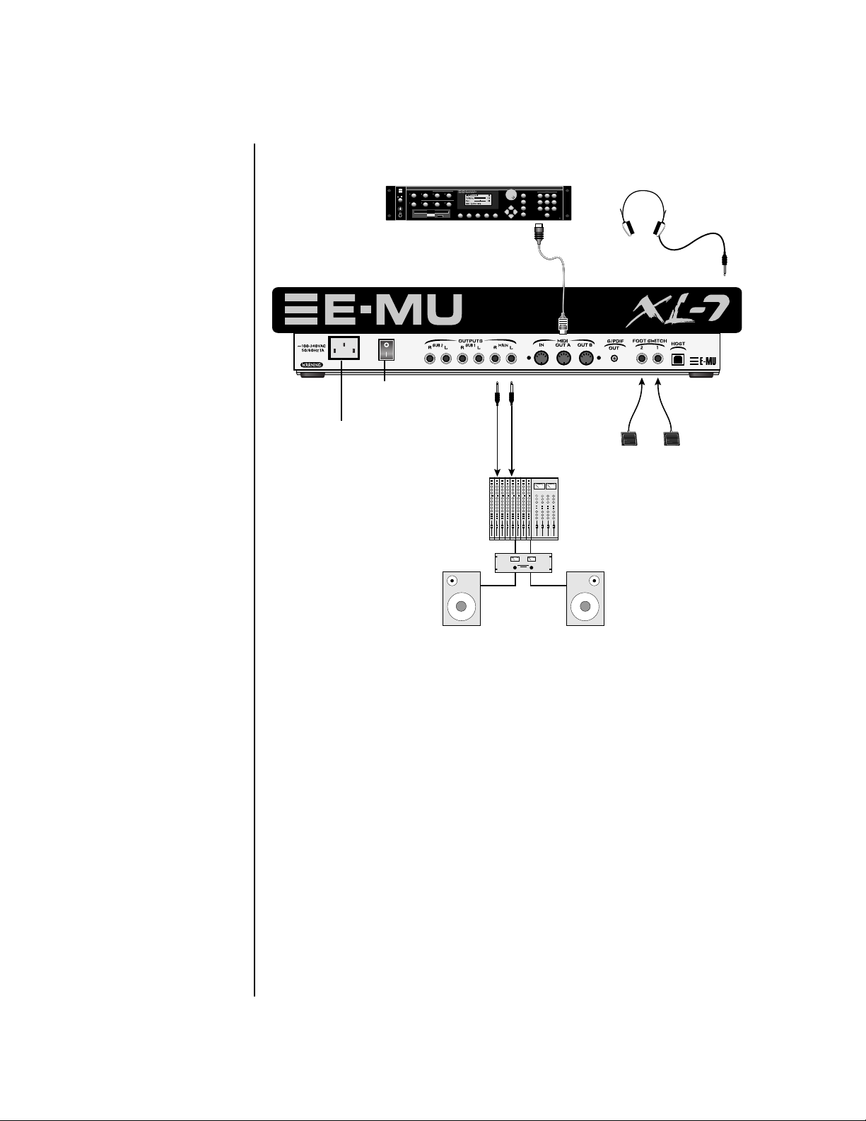
Using an External Sequencer ................................................................ 117
XL-7 Owners Manual
v
Page 6

Controllers Menu ................................................................. 119
Realtime Control Functions.......................................................................120
Keyboard Transpose ..............................................................................120
Keyboard Channel ................................................................................120
Aftertouch Curves .................................................................................120
Local Control On/Off ...........................................................................121
Footswitch Jack Function .....................................................................122
Trigger Buttons Function ......................................................................123
Trigger Buttons .....................................................................................124
Trigger Button Select .........................................................................124
Latch on/off .......................................................................................124
MIDI Key ...........................................................................................124
MIDI Channel ...................................................................................124
Destination ........................................................................................124
Key Velocity .......................................................................................124
Programmable Knobs ............................................................................125
Knob Preset Quick-Edit .........................................................................125
Real-time Controller Assignment .........................................................126
MIDI Footswitch Assign ........................................................................127
Tempo Controller .................................................................................127
Global Menu ........................................................................ 129
Multisetups.................................................................................................130
Restoring Multisetups ...........................................................................130
Multisetup Name ..................................................................................131
Saving Multisetups ................................................................................131
Defining Global Parameters.......................................................................132
Transpose/Tune .....................................................................................132
Bend Range ...........................................................................................132
Velocity Curve ......................................................................................133
Mix Output ...........................................................................................134
Master Effects .............................................................................................136
Effects Mode ..........................................................................................136
Effects Multi Mode Control ..................................................................136
Master FXA Algorithm ..........................................................................137
A Effect Types ....................................................................................137
FXA Parameters: Decay/HF Damping FxB -> FxA .................................138
FXA Send Amounts ...............................................................................138
Master FXB Algorithm ..........................................................................138
B Effect Types ....................................................................................139
FXB Parameters: Feedback/LFO Rate Delay Time .................................139
FXB Send Amounts ...............................................................................139
Miscellaneous Parameters ..........................................................................140
Edit All Layers Enable ...........................................................................140
User Key Tuning ...................................................................................140
Output Format ......................................................................................140
Screen Viewing Angle ...........................................................................141
vi E-MU Systems
Page 7

MIDI Menu ............................................................................143
Base Tempo ........................................................................................... 144
Rechannelize Input ............................................................................... 144
Keyboard Outputs MIDI .......................................................................146
Knobs Output MIDI .............................................................................. 146
Transmit MIDI Clock ............................................................................ 146
External Song Start/Stop ....................................................................... 146
Merge MIDI In to MIDI Out ................................................................. 147
MIDI In Channels ................................................................................. 147
MIDI Enable .......................................................................................... 147
Receive Program Change ...................................................................... 148
MIDI Program Change -> Preset ........................................................... 148
MIDI SysEx ID ....................................................................................... 149
MIDI SysEx Packet Delay ...................................................................... 150
Send MIDI System Exclusive Data ........................................................ 150
MIDI Mode ...........................................................................................152
Programming Basics .............................................................153
Modulation ................................................................................................154
Modulation Sources ...................................................................................155
Random Sources ...................................................................................156
Modulation PatchCords............................................................................. 156
Envelope Generators.................................................................................. 157
Tempo-based Envelopes .................................................................... 158
Envelope Repeat ................................................................................ 158
Low Frequency Oscillators (LFOs) .............................................................159
Clock Modulation...................................................................................... 160
Modulation Destinations........................................................................... 162
Modulation Processors............................................................................... 163
Preset Modulation Processors ....................................................................165
Using the Modulation Processors ......................................................... 167
More Examples ..................................................................................... 169
Dynamic Filters.......................................................................................... 171
What is a Filter? .................................................................................... 172
Parametric Filters ..................................................................................175
The Z-Plane Filter .................................................................................. 176
Signal Flow................................................................................................. 177
MIDI Channels & Real-time Controls .......................................................178
Bank Select Commands ........................................................................ 180
Stereo Mix Outputs.................................................................................... 181
XL-7 Owners Manual vii
Page 8

Preset Edit Menu .................................................................. 183
Preset Name ..........................................................................................184
Four Layer Architecture..............................................................................184
Selecting Layers .....................................................................................185
Defining Layer Parameters.........................................................................186
Selecting an Instrument ........................................................................186
Sound Navigator ................................................................................186
Defining Key Range ..............................................................................187
Defining the Velocity Crossfade Range ................................................189
Defining the Real-time Crossfade Range ..............................................191
Transposing the Instrument .................................................................194
Tuning ...................................................................................................195
Background: Transpose vs. Coarse Tuning .......................................195
Amplifier ...............................................................................................195
Volume Envelope ..................................................................................196
Selecting the Mode ............................................................................196
Defining the Volume Envelope .........................................................197
Chorusing the Layer .............................................................................198
Sound Start Offset and Delay ................................................................198
Non-Transpose Mode ............................................................................199
Solo Mode .............................................................................................199
Assign Group .........................................................................................200
Glide ......................................................................................................201
Z-Plane Filters ........................................................................................202
XL-7 Filter Types ...................................................................................202
Filter Types ........................................................................................202
Filter Parameters ................................................................................204
Filter Envelope ......................................................................................205
Defining the Filter Envelope .............................................................206
Auxiliary Envelope ................................................................................206
Low Frequency Oscillators (LFOs) ........................................................207
Shape .................................................................................................207
Sync ...................................................................................................208
Rate ....................................................................................................208
Delay ..................................................................................................210
Variation ............................................................................................210
PatchCords ............................................................................................211
Modulator Polarity ............................................................................212
Pitch Bend Range ..................................................................................214
Mix Output ...........................................................................................214
Common Preset Parameters.....................................................................215
Preset Effects .........................................................................................215
FXA Algorithm ......................................................................................217
A Effect Types ....................................................................................217
FXA Parameters .....................................................................................218
FXA Send Amounts ...............................................................................218
FXB Algorithm ......................................................................................218
B Effect Types ....................................................................................218
FXB Parameters .....................................................................................219
viii E-MU Systems
Page 9

FXB Send Amounts ............................................................................... 219
Preset Patchcords ..................................................................................219
Initial Controller Amount ....................................................................221
Keyboard Tuning ..................................................................................222
Preset Links ........................................................................................... 224
Preset Tempo Offset .............................................................................. 225
Audition Riff Selection .........................................................................225
Play Solo Layers .................................................................................... 225
Arpeggiator/Beats Menu ......................................................227
Arpeggiators ...............................................................................................228
Arp Controllers .....................................................................................229
Arpeggiator Resolution ......................................................................229
Arpeggiator Extension ....................................................................... 229
Arpeggiator Velocity .........................................................................229
Arpeggiator Gate ............................................................................... 229
Arpeggiator Interval .......................................................................... 229
Master Arpeggiator Parameters.................................................................. 229
Status ..................................................................................................... 230
Mode ..................................................................................................... 230
Note Value ............................................................................................231
Arpeggiator Pattern Speed .................................................................... 231
Pattern .................................................................................................. 231
Velocity ................................................................................................. 232
Gate Time .............................................................................................232
Extension Count ................................................................................... 233
Extension Interval ................................................................................233
Sync ...................................................................................................... 234
Pre-Delay ............................................................................................... 234
Duration ............................................................................................... 235
Post-Delay ............................................................................................. 235
Recycle .................................................................................................. 236
Keyboard Thru ...................................................................................... 236
Latch ..................................................................................................... 236
Send MIDI System Exclusive Data............................................................. 237
Editing a User Arpeggiator Pattern ....................................................... 238
Pattern Step Number ............................................................................ 238
Key ........................................................................................................ 238
Key Offset ..........................................................................................239
Tie ...................................................................................................... 239
Rest .................................................................................................... 239
Skip .................................................................................................... 239
End .................................................................................................... 239
Velocity ................................................................................................. 240
Duration ............................................................................................... 240
Repeat ................................................................................................... 240
User Pattern Name ................................................................................ 241
Multichannel Arpeggiating ..................................................................241
XL-7 Owners Manual ix
Page 10

x
Beats ...........................................................................................................242
Beats Mode ............................................................................................244
Status .................................................................................................244
Beats Channel ....................................................................................244
Trigger Channel .................................................................................244
Beats Controllers ...................................................................................247
Beat Velocity Group 1-4 ....................................................................247
Beat Xpose Group 1-4 .......................................................................247
Beat Busy ...........................................................................................247
Beat Variation ....................................................................................248
Beats Keys/Trigger Layout .....................................................................249
1-Bar Trigger Option .........................................................................249
Beats Keys Offset ...................................................................................250
Beats Part Velocity ................................................................................250
Beats Part Transpose .............................................................................251
Beats Part Group ...................................................................................252
Master Riff .............................................................................................252
Riff Tempo ............................................................................................253
Riff Controllers .....................................................................................253
Effects ................................................................................... 255
Effects Overview.........................................................................................255
The Effects Sends ..................................................................................255
Effect Types ................................................................................................257
Effect Parameters ...................................................................................257
Decay .................................................................................................258
High Frequency Damping .................................................................258
Feedback ............................................................................................258
LFO Rate ............................................................................................258
Delay ..................................................................................................258
Effects Programmed in the Preset ..............................................................259
Master Effects .............................................................................................260
Effects Mode ..........................................................................................262
Flexible Effects Control .........................................................................262
Using the Effects Channel Settings in Multi Mode ..........................264
Effect B Into Effect A .............................................................................264
General Effect Descriptions........................................................................266
Reverb ...................................................................................................266
Chorus ...................................................................................................267
Doubling ...............................................................................................267
Slapback ................................................................................................267
Stereo Flanger ........................................................................................267
Delay .....................................................................................................268
Stereo Delay ..........................................................................................268
Panning Delay .......................................................................................268
Dual Tap ................................................................................................268
Vibrato ..................................................................................................268
Distortion ..............................................................................................268
E-MU Systems
Page 11

Save/Copy Menu ..................................................................269
Save Pattern .......................................................................................... 269
Saving a Preset ...................................................................................... 270
Copying Information ...............................................................................271
Copy Preset ........................................................................................... 271
Copy Layer ............................................................................................ 271
Copy PatchCords .................................................................................. 272
Copy Preset PatchCords .......................................................................273
Copy Arpeggiator Settings .................................................................... 273
Copy Arpeggiator Pattern ..................................................................... 274
Copy Preset Bank .................................................................................. 274
Copy Sequencer Pattern ....................................................................... 275
Save Song ..............................................................................................275
Copy Song ............................................................................................ 276
Sound Authoring ....................................................................................... 277
Rename Flash SIMM .............................................................................278
Duplicate Flash ..................................................................................... 279
Create Random Preset................................................................................ 280
Preset Programming .............................................................281
Editing Presets............................................................................................ 281
Changing the Instrument .................................................................... 281
Changing the Tuning of an Instrument ..............................................282
Chorus .................................................................................................. 283
Volume Envelope .................................................................................283
Working with Filters ............................................................................. 285
Adding the Filter Envelope ............................................................... 287
Changing Filter Types ....................................................................... 289
Envelope Repeat ................................................................................ 289
Practice Modulating .............................................................................. 290
Troubleshooting ................................................................................... 291
Linking Presets........................................................................................... 292
Appendix ...............................................................................293
Front Panel Knob Functions...................................................................... 293
Knob Controller Descriptions ..............................................................294
Presets ........................................................................................................294
Preset Categories ................................................................................... 294
Preset Listing.............................................................................................. 295
Pattern Layout ..........................................................................................299
Pattern Listing............................................................................................ 300
Riff Listing.................................................................................................. 301
Instrument Listing .....................................................................................303
Velocity Curves.......................................................................................... 313
PatchCord Amount Chart .........................................................................315
Rhythmic Notation.................................................................................... 316
XL-7 Owners Manual xi
Page 12

Time Signatures..........................................................................................316
Block Diagrams ..........................................................................................317
Volume & Pan .......................................................................................317
Pads Routing .........................................................................................318
MIDI In .................................................................................................319
Block Diagrams .....................................................................................320
Triggers & Programmable Knobs ..........................................................320
Quick Edit .............................................................................................321
E-MU Expansion Sound Sets......................................................................322
Installing Sound SIMMs.............................................................................324
MIDI ...........................................................................................................327
Received Channel Commands .............................................................334
SysEx Specification ...............................................................................334
Technical Specifications .............................................................................335
Warranty ....................................................................................................336
Index .................................................................................... 339
xii E-MU Systems
Page 13

Introduction
XL-7 truly represents the ultimate melding of E-MU’s pristine audio quality
and cutting edge controller technologies, making it uniquely qualified to
serve as the control center of your MIDI studio or live performance rig.
Product Description
Upgradable Sounds
XL-7 contains a thorough collection of Electronica/Dance presets. These
sounds are rich in harmonic texture and a perfect complement to the
Z-plane filters. XL-7 contains three additional, user-upgradable sound
SIMM sockets, allowing you to mix and match sound sets according to your
needs. New sounds can be added as easily as plugging in a new 16MB or
32MB SIMM module. Each E-MU sound set has been meticulously crafted
to be the finest of its kind. Samples are matched across the keyboard,
perfectly looped, and rich in harmonic texture.
1024 Presets & more
XL-7 contains 512 user presets and 512 factory ROM presets, but it can be
expanded with literally thousands of ROM presets. (ROM presets are
automatically added when sound SIMMs are installed. As an example, a 32 MB
SIMM may contain up to 1024 ROM presets.) XL-7’s Sound Navigator makes it
easy to find the exact sound you want. It’s powerful, yet simple to use.
Velocity & Pressure Sensitive Pads
Thirteen velocity-sensitive pads with aftertouch allow you to perform live
or into the 16-track sequencer. These pads have been specifically designed
for the Command Station and are extremely responsive, capturing all the
subtle nuances of your performance.
Multi-Function Controllers
Multi-function buttons allow you to trigger sequences, arpeggiators and
loops internally or on any of your other MIDI devices. They can act as Note
Inputs for Grid or Step recording, Track Select, Mute or MIDI Trigger
buttons (latched or unlatched).
XL-7 Owners Manual 1
Page 14

Introduction
2
Sixteen real-time controller knobs are also multi-function controls. These
knobs make it a snap to edit and modify internal preset parameters.
Another useful mode allows the knobs to control volume and pan for all
sixteen MIDI channels. These controllers are fully programmable and can
control internal preset or other MIDI equipment on multiple MIDI
channels. They can be programmed to adjust multiple internal parameters
at once, allowing complex levels of control. For example, a single knob can
simultaneously turn up filter cutoff, while detuning one sample, and
adjusting the release time of the volume envelope. Virtually every synth
parameter in the XL-7 is controllable using the real-time knobs or by any
internal or external control source.
Super Sequencer
XL-7contains a powerful, yet simple to use 16-track interactive sequencer.
You can record in real-time, step and grid modes and can switch modes
without ever stopping your creative flow. Sixteen dedicated Mute/Select
buttons allow you to add, monitor and modify parts on the fly without
cumbersome menu scrolling. It’s never been this easy to lay down your
ideas. The XL-7 Command Station can store over 300,000 notes and you
can import and export MIDI files to and from your Mac or PC using E-MU’s
E-Loader program.
Multi-Channel Arpeggiators
XL-7’s Rhythmic Pattern Generator/Arpeggiator can play up to 32 synchronized arpeggiator patterns at once using a different sound for each! Patterns
can be edited using pattern flow commands such as: delay for 2 bars, play
for 4 bars, hold for 2 beats and repeat. You can program or download 100
user patterns in addition to the 200 factory patterns.
Ultra Powerful Synthesizer
The extremely flexible yet easy to use 4-layer synthesizer voices make it
easy to build sounds of any kind. Layers can be switched or crossfaded
using key position, velocity, real-time controllers or any modulation source.
128 voice polyphony ensures that you can play and sequence the most
complex material. XL-7 also contains 50 different 2nd to 12th order
resonant & modeling filters which are used to shape and modify over 1200
waveforms contained in 32 megabytes (MB) of ROM.
Sixty four modulation sources include three multistage envelopes and two
LFOs per layer, as well as full MIDI control over virtually every parameter.
The digital patch bay, with 24 cords per layer, (and 12 more cords per
preset) lets you connect modulation sources to 64 destinations in any
imaginable way. The patch bay also contains a set of arithmetic modifiers,
allowing you to create complex synthesis models. Synth parameters as well
as arpeggiator and BEAT tempos can be controlled from XL-7’s internal
clock (or an external MIDI clock). Up to 8 LFOs and 12 envelopes can be
perfectly synchronized at different rates. This is an extremely powerful
synthesizer!
E-MU Systems
Page 15

Introduction
24-bit Effects
Once you have created your preset, you can add richness to your sound
using XL-7’s 24-bit stereo effects. You can choose a different effects setup
for each preset from over 60 algorithms. XL-7’s effects section is actually
two separate effects processors with control over each wet/dry mix level on
four effects sends. Effects Processor “A” contains primarily ambiance
algorithms like reverb and delays, while effects processor “B” contains
primarily spectral algorithms such as chorus, flange, phase, distortion, and
delay. Effects can be linked to each preset or used globally to further
enhance your sound.
Other features include multiple solo, voice assignment and performance
modes for expressive control, 12 user-definable alternate tunings, and, of
course, an extensive MIDI implementation.
XL-7 Owners Manual 3
Page 16
Important Safety Instructions
4
Important Safety Instructions
Use in countries other than the U.S.A. may require the use of a different
line cord or attachment plug, or both. Refer all servicing to qualified service
personnel. There are no user serviceable parts or adjustments inside the
unit. There are no user serviceable parts inside the power supply enclosure.
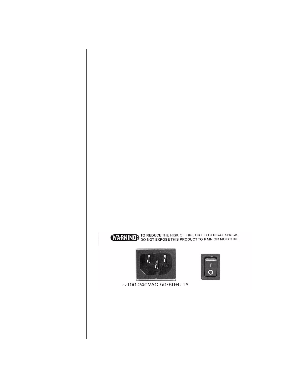
WARNING: To reduce the risk of fire or electric shock, do not expose this
product to rain or moisture.
Grounding
Instructions
Mains Switch
This product must be grounded. If it should malfunction or break down,
grounding provides a path of least resistance for electric current, reducing
the risk of electric shock. This product is equipped with a cord having an
equipment-grounding conductor and a grounding plug. The plug must be
plugged into an appropriate outlet properly installed and grounded in
accordance with all local codes and ordinances.
The front panel On/Off switch is a “Soft” power switch that can be used to
turn power on and off when the XL-7 is rack mounted. Use the AC power
switch on the rear panel if you wish to completely disconnect XL-7 from
the AC mains.
Danger!
E-MU Systems
Improper connection of the equipment’s grounding conductor can result in
the risk of electric shock. Check with a qualified electrician or service
personnel if you are in doubt as to whether the product is properly
grounded. Do not modify the plug provided with this product. If it will not
fit the outlet, have a proper outlet installed by a qualified technician.
Page 17
User
Maintenance
Instructions
Important Safety Instructions
1.
The XL-7 should be kept clean and dust free. Periodically wipe the unit
with a clean, dry, lint free cloth. Do not use solvents or cleaners.
2.
There are no user lubrication or adjustment requirements.
Caution -
Servicing instructions are for use by qualified personnel only. To reduce
the risk of electric shock, do not perform any servicing other than that contained
in these operating instructions unless you are qualified to do so. Refer all servicing
to qualified service personnel.
INSTRUCTIONS PERTAINING TO A RISK OF FIRE,
ELECTRIC SHOCK, OR INJURY TO PERSONS
READ THESE INSTRUCTIONS: When using electric products, basic precau-
tions should always be adhered to, including the following:
This symbol is intended to
alert you to the presence of
important operating and
maintenance (servicing)
instructions in the literature
accompanying the unit.
This symbol is intended to
alert you to the presence of
uninsulated dangerous
voltage within the product’s
enclosure that may be of
sufficient magnitude to
constitute a risk of electric
shock to persons.
Read all instructions before using XL-7.
1.
Keep these instructions.
2.
Heed all warnings.
3.
Follow these instructions.
4.
Do not use near water.
5.
Clean only with a dry cloth.
6.
Install in accordance with E-MU’s instructions. Do not block any
7.
openings. This apparatus should be situated so that its location or
position does not interfere with proper ventilation. The ventilation
should not be impeded by covering the ventilation openings with items
such as newspapers, tablecloths, curtains, etc.
Do not install near any heat sources such as radiators, heat registers,
8.
stoves, or other apparatus (including amplifiers) which produce heat.
Do not defeat the safety purpose of the polarized or grounding-type
9.
plug. A polarized plug has two blades with one wider than the other. A
grounding-type plug has two blades and a third grounding prong. The
wide blade or the grounding prong are provided for your safety. If the
provided plug does not fit into your outlet, consult an electrician for
replacement of the obsolete outlet.
Protect the power cord from being walked on or pinched, particularly at
10.
plugs, convenience receptacles, and at the point where they exit from
the apparatus.
Use only attachments/accessories specified by E-MU Systems.
11.
Use only with the cart, stand, tripod, bracket, or table specified by
12.
E-MU or sold with the apparatus. When a cart is used, use caution when
moving the cart/apparatus combination to avoid injury from tip-over.
Unplug the XL-7 from the power outlet during lightning storms or
13.
when left unused for a long period of time.
Refer all servicing to qualified service personnel. Servicing is required
14.
when the apparatus has been damaged in any way, such as power
XL-7 Owners Manual 5
Page 18
Important Safety Instructions
This symbol is intended to
alert you to use caution when
moving a cart/apparatus
combination to avoid injury.
6
•
•
•
•
•
supply cord or plug is damaged, liquid has been spilled or objects have
fallen into the apparatus, the apparatus has been exposed to rain or
moisture, the does not operate normally or has been dropped.
No open flame sources, such as lit candles, should be placed on the
15.
apparatus.
The apparatus is designed for use in moderate climates.
16.
The apparatus shall not be exposed to dripping or splashing. No objects
17.
filled with liquids, such as vases, shall be placed on the apparatus.
To reduce the risk of injury, close supervision is necessary when using
18.
the apparatus near children.
The apparatus should be connected only to a power supply of the type
19.
described in the operating instructions and marked on the product.
This product, in combination with an amplifier and headphones and
20.
speakers, may be capable of producing sound levels that could cause
permanent hearing loss. Do not operate for a long period of time at a
high volume level or at a level that is uncomfortable. If you experience
any hearing loss or ringing in the ears, consult an audiologist.
Radio and
Television
Interference
The equipment described in this manual generates and uses radiofrequency energy. If it is not installed and used properly —that is, in strict
accordance with our instructions— it may cause interference with radio
and television reception.
This equipment has been tested and complies with the limits for a Class B
computing device in accordance with the specifications in Subpart J of Part
15 of the FCC rules. These rules are designed to provide reasonable
protection against such interference in a residential installation. However,
there is no guarantee that the interference will not occur in a particular
installation, especially if a “rabbit ear” TV antenna is used.
If XL-7 does cause interference to radio or television reception, you can try
to correct the interference by using one or more of the following measures:
Turn the television or radio antenna until the interference stops.
Move XL-7 to one side or the other of the television or radio.
Move XL-7 farther away from the television or radio.
Plug XL-7 into an outlet on a different circuit than the television or
radio.
Consider installing a rooftop antenna with a coaxial lead-in between the
antenna and television set.
E-MU Systems
Page 19

Foreign Language Warnings - German
Foreign Language Warnings
- German
Wichtige
Sicherheitsvorschriften
Erdungsinstruktionen
Gefahr
In Ländern ausserhalb den U.S.A. können andere Kabel oder Stecker
notwendig werden. Zur Verminderung des Risikos von Feuer oder eines
elektrischen Schlages übergebe man den Service an qualifizierte Fachleute.
Das Gerät niemals Regen oder Nässe aussetzen.
Das Gerät muss geerdet sein. Bei einem Defekt oder Ausfall bietet Erdung
dem elektrischen Strom den Weg des geringsten Widerstandes und
reduziert das Risiko eines Schlages. Dieses Gerät ist mit einem geerdeten
Kabel und Stecker ausgerüstet. Der Stecker muss in eine passende,
einwandfrei montierte und geerdete Steckdose in Übereinstimmung mit
den örtlichen Vorschriften eingeführt werden.
Unvorschriftsgemässer Anschluss des Gerätes kann zum Risiko eines
elektrischen Schlages führen. Im Zweifelsfalle über die ordnungsgemässe
Erdung soll ein qualifizierter Elektriker oder eine Serviecestelle beigezogen
werden. Ändern Sie den mitgelieferten Stecker nicht. Sollte er nicht in die
Steckdose passen, soll die einwandfreie Installation durch einen qualifizierten Techniker erfolgen.
Vorsicht
Wird der XL-7 (Modell Nummer 7750)in einem Rackgestell montiert, muss
ein offener 19-Zollrahmen verwendet werden.
XL-7 Owners Manual 7
Page 20
Foreign Language Warnings - German
Unterhaltsin-
1.
struktionen
für anwender
2.
3.
8
XL-7 soll sauber und staubfrei gehalten werden. Das Gerät mit einem
sauberen und säurefreien Tuch periodisch abreiben. Keine Lösungsoder Reinigungsmittel anwenden.
Schmieren und Justieren sind nicht notwendig.
Bei weiteren Servicefragen wende man sich an eine qualifizierte Service-
stelle.
Vorsicht
Dieses Symbol weist den
Anwender auf wichtige
Gebrauchs- und Service-
Vorschriften in den beilieg-
enden Drucksachen.
Dieses Symbol verweist auf
nicht-isolierte Stromspannungen im Geräte-Innern,
welche zu einem elektrischen
Schlag führen könnten.
Diese Gebrauchsanweisungen sind nur für qualifizierte Techniker
beabsichtigt. Um die Gefahr eines elektrischen Schlages zu vermeiden,
sollen Sie keine Arbeit unternehmen, die nicht in diesen Instruktionen
vorgeschrieben ist. Wenden Sie Sich bei weiteren Servicefragen an eine
qualifizierte Servicestelle.
INSTRUKTIONEN BETR. FEUERRISIKO,
ELEKTROSCHOCK ODER VERLETZUNG VON
PERSONEN
WARNUNG; Beim Einsatz elektrischer Geräte sollten
folgende Vorsichtsmassregeln stets beachtet werden:
1.
Lesen Sie vor dem Einschalten des XL-7 alle Instruktionen.
2.
Zur Vermeidung von Verletzungsrisiken müssen Kinder bei eingeschaltetem XL-7 sorgfältig überwacht werden.
3.
XL-7 nicht in der Nähe von Wasser in Betrieb nehmen -- z.B. in der
Nähe von Badewannen, Waschschüsseln, auf nassen Gestellen oder am
Swimmingpool.
4.
XL-7 stets so aufstellen, dass seine Belüftung nicht beeinträchtigt wird.
5.
XL-7 nicht in der Nähe von Hitze aufstellen, wie Heizkörper, offenem
Feuer, Öfen oder von Backöfen.
6.
XL-7 ausschliesslich mit einem Netzgerät gemäss Bedienungsanleitung
und Gerätemarkierung verwenden.
7.
Dieses Gerät kann bei Verwendung von Kopfhörern und Verstärkern
hohe Lautpegel erzeugen, welche zu bleibenden Gehörschäden führen.
Arbeiten Sie nicht während längerer Zeit mit voller Lautstärke oder
hohem Lautpegel. Stellen Sie Gehörverlust oder Ohrenläuten fest,
wenden Sie sich an einen Ohrenartz.
8.
XL-7 kann mit einem polarisierten Kabelstecker (mit ungleichen
Stiften) ausgerüstet sein. Das geschieht für Ihre Sicherheit. Können Sie
den Stecker nicht in die Steckdose einführen, ändern Sie nicht den
Stecker ab, sondern wenden Sie sich an einen Elektriker.
E-MU Systems
Page 21

Foreign Language Warnings - German
Das Netzkabel des XL-7 bei längerem Nichtgebrauch aus der Steckdose
9.
ziehen.
Vermeiden Sie sorgfältig das Eindringen von Gegenständen oder
10.
Flüssigkeiten durch die Gehäuseöffnungen.
Das Gerät soll durch qualifizierte Serviceleute gewartet werden, falls:
11.
A. das Netzkabel beschädigt wurde, oder
B. Gegenstände oder Flüssigkeit in das Gerät gelangten,
C. das Gerät Regen ausgesetzt war, oder
D. das Gerät nicht normal oder einwandfrei arbeitet, oder
E. das Gerät stürzte oder sein Gehäuse beschädigt wurde.
Servicearbeiten sollten nur qualifizierten Fachleuten anvertraut werden.
12.
DIESE INSTRUKTIONEN AUFBEWAHREN
XL-7 Owners Manual 9
Page 22

Foreign Language Warnings - French
Foreign Language Warnings French
Instructions
de Sécurité
Importantes
Instructions
de Mise à la
Te r r e
Danger
Une utilisation dans des pays autres que les U.S.A. peut nécessiter l’usage
d’un cordon d’alimentation différent. Afin de réduire les risques d’incendie
ou d’électrocution, référez-vous à un personnel de service qualifié, et
n’exposez pas cet appareil à la pluie ou à l’humidité.
Cet appareil doit être relié à la terre. Dans le cas d’une malfonction
éventuelle, la terre fournit un passage de moindre résistance pour le
courant électrique, réduisant ainsi les risques d’électrocution. Le XL-7 est
équipé d’un cordon muni d’un conducteur et d’une fiche devant être
branchée dans une prise appropriée et reliée à la terre en conformité avec
les normes locales.
Une connexion incorrecte peut résulter en des risques d’électrocution.
Vérifiez avec un technicien qualifié si vous avez des doutes quant à la
connexion. Ne modifiez pas vous-même le cordon d’alimentation livré avec
cet appareil; s’il ne rentre pas dans la prise, faites-en installer un autre par
un technicien qualifié.
Attention
Instructions
de
Maintenance
10
E-MU Systems
Si le XL-7 (Model 7750) est installé dans un rack, utilisez un rack standard
ouvert de 48.25cm.
1.
Le XL-7 doit être maintenu propre et sans poussière. Nettoyez-le
périodiquement à l’aide d’un chiffon propre et non-pelucheux.
N’utilisez pas de solvants, ou d’autres produits de nettoyage.
2.
Aucune lubrification et aucun réglage ne sont nécessaires de votre part.
3.
Pour tout autre service, référez-vous à un personnel qualifié.
Page 23
Ce symbole vous alerte de la
présence d’instructions
importantes d’opération et
de maintenance dans la
notice accompagnant
l’appareil.
Ce symbole vous alerte de
la présence d’un voltage
non-isolé dangereux à
l’intérieur de l’appareil,
pouvant être d’une
magnitude suffisante pour
constituer un risque
d’électrocution.
Foreign Language Warnings - French
Instructions Concernant les Risques d’Incendie,
d’Electrocution, ou de Blessures Corporelles.
ATTENTION: Lorsque vous utilisez des appareils électriques,
certaines précautions élémentaires doivent toujours être prises,
incluant les suivantes:
Ces instructions de dépanage sont destinées uniquement aux personnes
qualifiées. Afin d’éviter les risques d’électrocution, n’effectuez que les opérations décrites dans ce manuel, à moins que vous ne soyez qualifiê pour cela.
Faites effectuer toute r’eparation par une personne qualifié.
Lisez bien toutes les instructions avant d’utiliser le XL-7.
1.
Afin de réduire les risques de blessures, une attention particulière est
2.
nécessaire en la présence d’enfants en bas âge.
3. N’utilisez pas le XL-7 dans ou près d’endroits humides - par exemple
près d’une baignoire, d’un lavabo, dans les toilettes, dans une cave
humide, sur un bar fréquenté, en présence d’un bull-dog en rut, ou
dans une piscine pleine. Protégez cet appareil de tout liquide,
éclaboussure ou fuite.
4. Le XL-7 doit être placé de façon à ce que sa position n’interfére pas avec
sa propre ventilation.
5. Le XL-7 doit être placé loin de sources de chaleur telles que des radia-
teurs, cheminées, fours, ou groupies en chaleur.
6. Le XL-7 doit uniquement être connecté à une alimentation du type
décrit dans les instructions d’opération et tel qu’indiqué sur l’appareil.
7. Une attention particulière doit être observée quant aux objets pouvant
tomber et aux liquides pouvant être versés sur et à l’intérieur de le XL-7.
8. Le XL-7 peut être équipé d’une fiche secteur polarisée (avec une broche
plus large que l’autre). C’est une mesure de sécurité. Si vous ne pouvez
pas brancher cette fiche dans une prise, ne neutralisez pas cette sécurité.
Contactez plutôt un électricien pour remplacer la prise obsolète.
9. Evitez de marcher sur le cordon d’alimentation ou de le coincer,
particuliêrement prês des prises de courant, des boitiers ‘electriques dt
du point de sortie de l’appareil.
10. Le cordon d’alimentation de le XL-7 doit être débranché lorsque ce
dernier n’est pas utilisé pendant une longue période.
11. Cet appareil, combiné avec un amplificateur, des haut-parleurs, et/ou
un casque, est capable de générer des niveaux sonores pouvant
occasionner une perte de l’ouïe permanente. Ne travaillez pas trop
longtemps à un volume trop élevé ou même inconfortable. Si vous
observez une perte de l’audition ou un bourdonnement dans les
oreilles, consultez un O.R.L.
12. N’utilisez que les accessoires sp’ecifi’es par E-MU Systems.
13. Cet appareil doit être examiné par un personnel qualifié lorsque:
A. Le cordon d’alimentation a été endommagé, ou
XL-7 Owners Manual
11
Page 24

Foreign Language Warnings - French
14. Tout service doit être effectué par un personnel qualifié.
SAUVEGARDEZ CES INSTRUCTIONS
B. Des objets sont tombés, ou du liquide a été versé sur/à l’intérieur
de l’appareil, ou
C. Le XL-7 a été exposé à la pluie, ou
D. Le XL-7 est tombé, ou
E. Le XL-7 ne fonctionne pas normalement, ou affiche un
changement radical de performance.
Interférences
Radio et
Télévision
L’appareil décrit dans cette notice génére et utilise une énergie de
fréquence-radio. S’il n’est pas installé et utilisé correctement - c’est à dire en
suivant strictement nos instructions - il peut occasionner des interférences
avec la réception d’une radio ou d’une télévision.
Cet appareil a été testé et est conforme aux normes de Classe A en accord
avec les spécifications du paragraphe J de la section 15 des lois FCC. Ces lois
sont désignées pour fournir une protection raisonnable contre de telles
interférences dans une installation résidentielle. Toutefois, il n’est pas
garanti qu’aucune interférence n’apparaisse dans des installations
particulières, et plus spécialement lorsqu’une antenne de télévision en
«oreilles de lapin» est utilisée.
Si le XL-7 occasionne des interférences , vous pouvez essayer de les corriger
en utilisant une ou plusieurs des mesures suivantes:
• Tournez l’antenne de la télé ou de la radio jusqu’à ce que les interférences disparaissent.
• Déplacez le XL-7 d’un côté ou de l’autre de la télé ou de la radio.
• Eloignez le XL-7 de la télé ou de la radio.
• Branchez le XL-7 sur une prise différente que la télé ou la radio.
• Installez une antenne sur le toit munie d’une connexion coaxiale entre
elle et le poste de télévision.
12 E-MU Systems
Page 25

Foreign Language Warnings - French
Declaration of Conformity
Manufacturer:
E-MU Systems
1600 Green Hills Road
Scotts Valley, CA 95067-0015 USA
We hereby declare that the equipment listed herin conforms to the
harmonized standards of the following European Commission Directives:
89/336/EEC and 72/23/EEC.
Trade Name: XL-7
Model Number: 7750
Under 89/336/EEC as amended by 92/31/EEC, and 93/68/EEC
In accordance with EN 55103-1:1996, Emission Environments E4
In accordance with EN 55103-2:1996, Immunity Environments E4
Test information is contained in a report by Atlas Compliance and
Engineering, Inc.
Dated July 5, 2001
Report No.: 0126EMUx17_103
Under 73/23/EEC as amended by 93/68/EEC
In accordance with EN 60950 with amendments A1, A2, A3, A4, A11
This Declaration is made July 5, 2001
XL-7 Owners Manual 13
Page 26

Foreign Language Warnings - French
14 E-MU Systems
Page 27

Setup
This section thoroughly describes how to set up your new XL-7 for use.
Setup includes unpacking instructions, how to hook up the unit to your
sound system and, most importantly, how to turn the thing on and off.
Unpacking Carefully remove XL-7 from the packaging material. Take care to save the
packing materials in case you need to transport the unit. Check to make
sure all components are included and in good condition. If there are
missing or damaged components, contact E-MU Systems immediately for
replacement or repair.
The XL-7 box should include the following components:
• XL-7 unit
• Power cable
• This operation manual
• Command Station CD-ROM
The following optional accessories are NOT included with your XL-7, but
are available from your E-MU dealer for a nominal fee:
• Model 7770 - Rack Mounting Ears
• Model 7771 - XL-7 Gig Bag
• Model 7773 - Locking 12VDC Lamp
XL-7 Owners Manual 15
Page 28
Setup
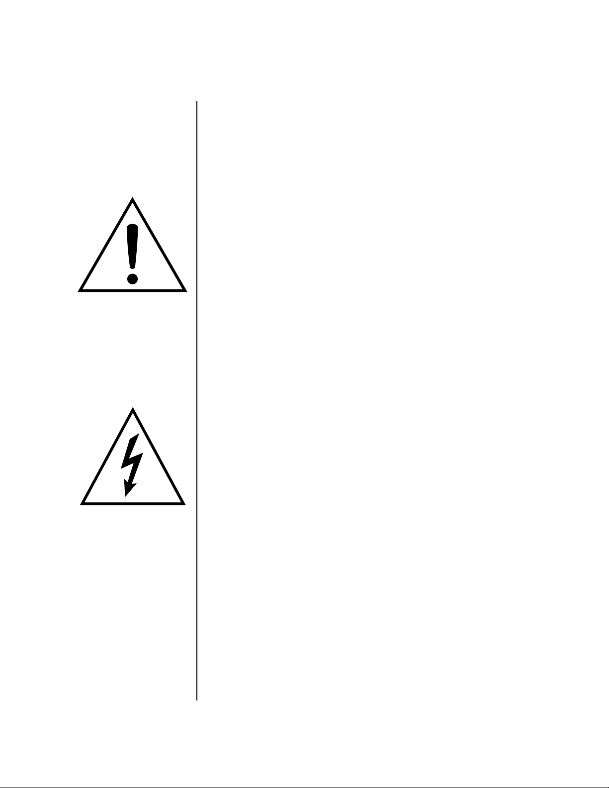
Basic Setup
Connection Instructions
Basic Setup
Basic Setup
TO REDUCE THE RISK OF FIRE OR ELECTRICAL SHOCK,
DO NOT EXPOSE THIS PRODUCT TO RAIN OR MOISTURE.
110V/220V
50-60 Hz
(auto-select)
MIDI Sound Module
SAMPLE
MASTER/GLOBAL
TRANSPOSE DIGITAL PROCESSINGSAMPLE MANAGEMENT
I
O
PRESET
MULTIMODE
PRESET MANAGEMENT DYNAMIC PROCESINGPRESET DEFINITION
VOLUME
Power
Switch
DRIVE SELECT LOAD SAVE AUDITION TRIGGER MODE
MIDI In
Main Outs to Mixer In
Amp
INC/YES
DEC/NO
ENTER
ESCAPE
Mixer
TRIGGERS
ABC
DEF
123
JKL
MNO
GHI
456
TUV
WXY
PRS
789
QZ
0
MIDI
Footswitch Footswitch
The Headphone
Output is located
on the Front Panel
The Right Main output
jack carries a mono mix of the
left and right channels when the
Left Main plug is not plugged in.
The Left Main output jack is a
stereo jack carrying both
channels when the right output
jack is empty.
Speakers
Power Switch & AC Receptacle
The AC power switch located on the rear panel is a “hard” power switch.
The front panel On/Off switch is a “soft” power switch that can be used to
turn power on and off when the XL-7 is rack mounted. There is no 110/220
Volt power selector switch since XL-7 utilizes an auto-switching power
supply which accepts from 100V-250V, 50-60Hz.
Outputs
In order to reproduce XL-7’s wide dynamic range and frequency response,
use a high quality amplification and speaker system and a stereo setup is
highly desirable The headphone output is the same as the Main output
signal. The headphone jack is located on the left side of the front panel.
Footswitches 1 & 2
Connect one or more momentary footswitches for additional control. XL-7
auto-senses either normally-open or normally-closed switches when they
are plugged in. Their functions are programmable in the Controllers,
Footswitch menu and the Preset Edit, PatchCord menu.
16 E-MU Systems
Page 29
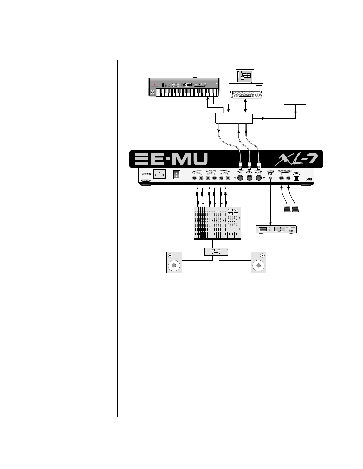
Studio Setup
MIDI Controller
(MIDI Keyboard, etc.)
REAL TIME CONTROLLERS
ASSIGNABLE KEYS
SEQUENCER
TO REDUCE THE RISK OF FIRE OR ELECTRICAL SHOCK,
DO NOT EXPOSE THIS PRODUCT TO RAIN OR MOISTURE.
Setup
Studio Setup
PRESET
SAMPLE
LEVEL
EXIT
ENTER
PAGE
PRESET SELECT
RETURN
EMULATOR
0.987654321
MIDI OutMIDI In
Out
In
MIDI
Interface
channels
1A-16A
Computer
In
In
channels
1B-16B
Out
Additional
MIDI
Devices
MIDI In
Footswitches
Mixer
S/PDIF = Main Outs
Digital Audio Device
Amp
MIDI In
In this setup, XL-7 is controlled by MIDI messages received at the MIDI
input, which are routed by a computer MIDI interface. Any MIDI
controller, such as a MIDI keyboard or a computer, can control the module.
MIDI Out
XL-7 contains two MIDI output ports (A & B) so that it can transmit on 32
MIDI channels instead of the usual 16.Audio Outputs
Three sets of programmable stereo outputs (Main, Sub 1, and Sub 2) are
provided. The internal effects are available only on the Main outputs.
Specific presets (or MIDI channels) can be routed to one of these stereo
pairs in order to be processed further or mixed separately. The S/PDIF
output duplicates the function of the main outputs.
Channels 01A-16A
normally go to MIDI Out port A
and channels 01B-16B
normally go to MIDI Out port B.
Footswitches 1 & 2
The two footswitch inputs accept either normally-open or normally-closed
momentary footswitches and are programmable in the Controllers,
Footswitch menu and the Preset Edit, PatchCord menu.
XL-7 Owners Manual 17
Page 30
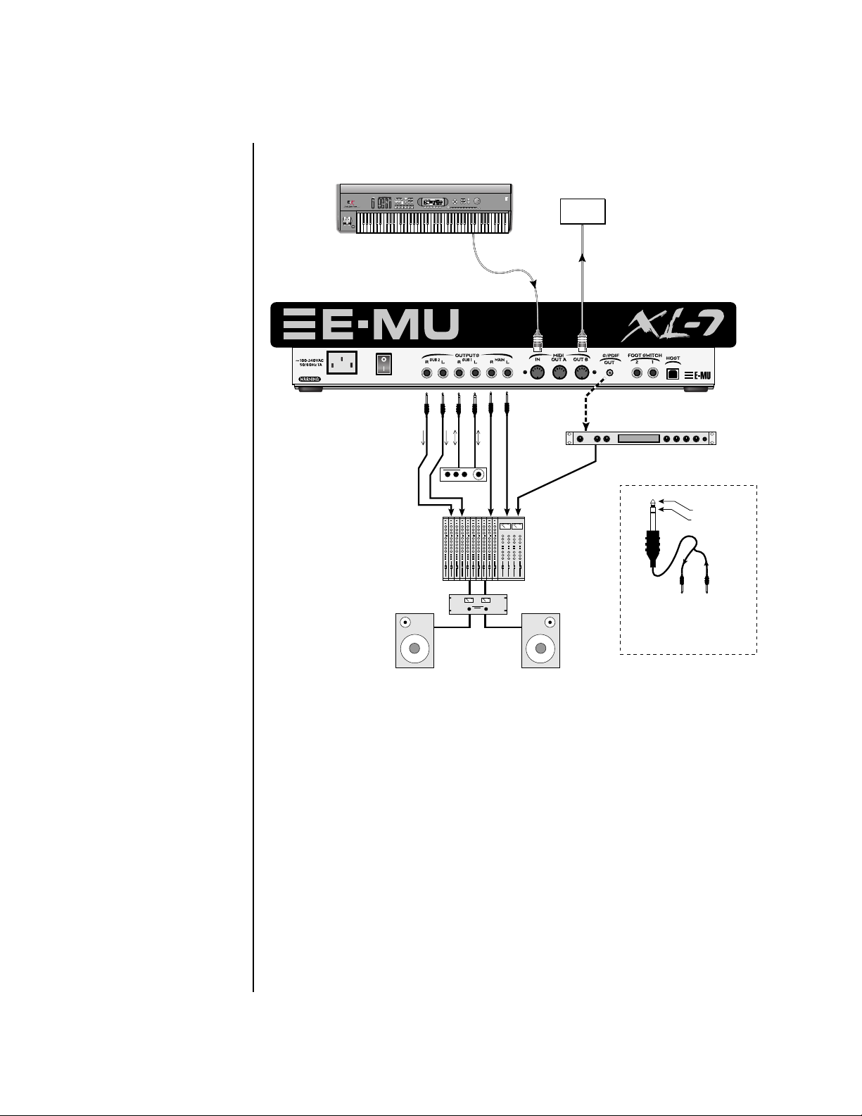
Setup
Performance Setup
Performance Setup
MIDI Controller
(MIDI Keyboard, Sequencer)
REAL TIME CONTROLLERS
TO REDUCE THE RISK OF FIRE OR ELECTRICAL SHOCK,
DO NOT EXPOSE THIS PRODUCT TO RAIN OR MOISTURE.
ASSIGNABLE KEYS
PRESET
SAMPLE
SEQUENCER
EMULATOR
MIDI Out
Send
Effect Device
LEVEL
EXIT
ENTER
PAGE
PRESET SELECT
RETURN
0.987654321
Send/Return
Main Outs to Mixer In
Additional
MIDI
Devices
MIDI In
Effect: Swirling Reverb
Parameter Edit
Digital Effect
S/PDIF In
Volume Mix Data Entry Control 1 Control 2 Control 3 Control 4
Analog Out
Sub Output
Return
(To Main Output)
Tip Ring
To Effect From Effect
SEND/RETURN CABLE
Signal is sent out on tip of plug and
returned to main outputs via ring of plug.
MIDI In
In this setup, XL-7 is additionally controlled by a MIDI keyboard.
MIDI Out
In this setup, XL-7 is controlling another MIDI sound module using its
‘“B” MIDI Port. MIDI data from the keyboard can be merged with XL-7‘s
MIDI data and then be retransmitted out port B. See page 146.
Audio Outputs
The Sub 1 and Sub 2 output jacks are stereo jacks. The tip of each jack
(accessed when a standard phone plug is inserted) connects to the left or
right output of that group. The S/PDIF output is a digital copy of the stereo
signal on the main outputs.
If you insert a stereo plug into one of the Sub Outputs, the ring of the plug
serves as a signal Return which sums into the Main outputs.
18 E-MU Systems
Page 31
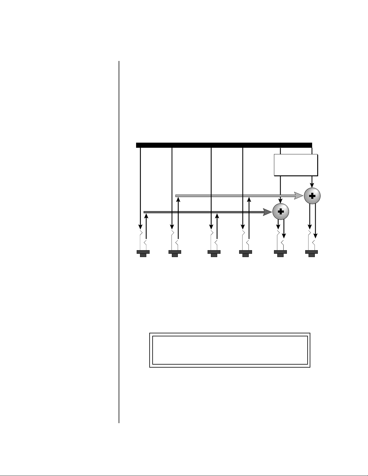
Setup
Power Down Sequence
Therefore, the Sub 1 and Sub 2 jacks can serve as effect sends and
returns in order to further process selected instruments and then
return them to the main mix.
You can use the Sub 1 and Sub 2 jacks as send/returns in order to further
process selected XL-7 presets without using the effects bus on the mixing
board. In a pinch, the effect returns can be used to sum additional instruments into the main outputs. It’s like having an extra line mixer when you
need more inputs!
Output Section
Effects
Processors
L Bus
Power Down
Sequence
R Bus
Tip
You can use the Sub 1 and Sub 2 jacks as effect returns to the Main Outputs.
To avoid accidentally turning off the power while playing XL-7, the front
panel power switch incorporates a five second “fail-safe” feature when
powering down. Once the power down sequence has begun, you have five
seconds to press the power switch again and stop XL-7 from turning off.
Tip
Ring
RL
SUB 2
Note that the Effects Processors are only routed to the Main Outputs.
Ring
Tip
Tip
Ring
RL
SUB 1
Ring
RL
MAINS
POWERING DOWN : 4
****
Press On / Off to Abort . . .
Rack Mounting XL-7 XL-7 can be rack mounted if you so desire. You’ll need (6) rack spaces to fit
XL-7 into your rack. The black end caps remove easily with three screws to
reduce the width to 19 inches. Rack mounting ears are available from your
E-MU dealer (Model 7770).
XL-7 Owners Manual 19
Page 32

Setup
Rack Mounting XL-7
20 E-MU Systems
Page 33

Instant Gratification
This section presents step-by-step instructions for the most fundamental
operations to get you up and running as quickly as possible.
Playing Patterns & Songs
When you turn XL-7 on, it comes up in Pattern mode. XL-7 comes with
over a hundred factory patterns. The Pattern screen is shown below.
T
01 STOP Ln:08 Bar:01 .1
0
000
To Play Patterns
1. Select a pattern using the data entry control.
2. Press the Play button, located near the center of the unit. The pattern
begins playing and the lower line of the display changes.
T
CurPat: 002
3. While the pattern is playing, select another pattern using the data
entry control. The name of the pattern to be played next is now shown.
Notice that the Home/Enter LED is now flashing.
Ambideep
01 STOP Ln:08 Bar:01 .1
0
NextPat: 0020
T
01 STOP Ln:08 Bar:01 .1
0
Club Luv
015
4. Press the Home/Enter button to select the new pattern. The lower line
of the display now shows the numbers of the Current and Next
XL-7 Owners Manual 21
Page 34

OO
OO
XL-7’s buttons have
been designed so that you can
slide your fingers across them to
quickly mute and unmute
tracks.
Instant Gratification
Playing Patterns & Songs
patterns. The new pattern will begin playing when the current pattern
has finished.
T
01 STOP Ln:08 Bar:01 .1
0
CurPat: 002
5. Select a new pattern, press Stop, then press Play to change patterns
NextPat: 0220
without waiting for the current pattern to end.
Track Muting
6. Press the Track Enable/Mute buttons to bring tracks in and out. Every
factory pattern has from eight to sixteen tracks. The LED in each button
illuminates when a track is enabled (unmuted). The diagram below
shows the default factory track assignments.
Kick 1
Snare 1 Hi-Hat 1
Perc 1
or Fill 1
Kick 2 Snare 2 Hi-Hat 2
Perc 2
or Fill 2
Instr or
Perc 1
Main
Bass
Instr or
Perc 2
Main
Lead
Instr or
Perc 3
Main
Comp
Instr or
Perc 4
Instr or
Perc 5
Instr or
Perc 6
Instr or
Perc 7
Instr or
Perc 8
Track Mixing
7. Press the Mix button (located beneath the LCD) while a pattern is
playing. The Channel Volume display screen appears, showing the
volumes of all 32 channels.
CH VOLS
01A:125
8. Now press the Controller Function Select button (located above the
controller knobs) twice so that Volume is selected.
9. The sixteen controller knobs now function as volume controls for MIDI
channels 01A-16A.
22 E-MU Systems
Page 35

OO
OO
If you move the cursor
underneath the Preset Name
before changing the preset,
another bass preset will be
selected.
Instant Gratification
Playing Songs
• While we’re on the subject of Tracks and Channels, it might be a good
time to mention that in all the factory patterns, a given track will control
the MIDI channel of the same number. That means Track 1 will play the
preset on channel 01A, track 2 will play channel 02A and so on up to 16.
Feel free to turn the knobs and remix the pattern. The LEDs next to the
knobs flash to indicate activity on that channel/track.
Change the Sound
10. Adjust your remix so that track 9 (the bass) is the most prominent
instrument in the mix.
11. Press the Preset View button and select Track 9 using the Track/
Channel buttons to the left of the LCD.
12. Now repeatedly press the Controller Function Select button until
“Quick Edit” is selected.
13. Now the knobs control the bass sound. You know what to do.
14. Turn the data entry control to completely change the preset.
15. Use the Track/Channel select buttons to change any of the presets. In
XL-7’s default mode, the rubber keypads are active on whichever preset
is showing in the preset view screen. They can be set to always play a
specific channel in the Controllers menu (page 120).
• Nothing is made permanent until you save the pattern or preset, so play
around as much as you like.
Jump Back
16. You can jump between Volume mode, Quick Edit mode or Pattern
mode at any time without missing a beat. Select a new pattern, tweak
parameters, change the mix, enable or mute tracks.
Playing Songs Now that you’ve explored Pattern mode a little, check out Song mode. In its
most basic form, a song is just a sequence of patterns chained together one
after another.
OO
OO
Press the Pattern Mode
button while a Song is playing
to loop on the current pattern.
Pressing Song Mode continues
playing the song.
To Play a Song
1. Select Song mode by pressing the Song button located underneath the
LCD. (Stop the sequencer first.)
2. Select one of the factory programmed songs using the data entry
control.
3. Press Play. The song begins playing.
XL-7 Owners Manual 23
Page 36

Instant Gratification
Playing Demo Sequences
Playing Demo
Sequences
XL-7 has several factory demonstration sequences that let you hear what
this incredible machine can do. The actual number of demo sequences
depends on which ROM sounds sets are installed. You can play these demo
sequences by accessing the Demo Sequence page.
DEMO SEQUENCES XL-7
Arctic Drift
To Play a Demo Sequence
1. Press and hold the Song and Pattern buttons at the same time to enter
the Demo Sequence page. The screen shown above appears.
2. Select a sequence using the data entry control. The Enter LED will be
flashing.
3. Press the Enter button to begin playing the selected sequence. The
following screen appears.
PLAYING: Arctic Drift
Press ENTER to stop
4. Press the Enter button again to stop playing the sequence.
5. When a demo sequence plays to the end, the next demo will automati-
cally begin playing. The screen will display the new demo name.
6. With the sequence stopped, press any other button to Exit demo
sequence mode.
Auditioning Presets The front panel audition button allows you to hear any preset in XL-7
without even playing a note! When the Audition button is pressed, the
button’s LED will illuminate and a short “Riff” (programmed as part of the
preset) will play. The Riff is latched on and plays continuously until the
button is pressed again. Presets can be changed while Audition is latched.
OO
OO
To audition presets with
their programmed effects, switch
to Omni or Poly mode (located
in the MIDI menu). Remember
to switch back to Multi mode
before playing sequences again.
The top line of the Preset View display changes to show the MIDI Bank
Select controller values needed to select the preset being auditioned. This is
an extremely handy feature when sequencing.
24 E-MU Systems
Page 37

Instant Gratification
Selecting and Quick Editing Presets
Bank MSB:007 LSB:1 XL-7
1
252 key: SynhissOrgan
To Audition a Preset
1. Select Preset View mode by pressing the preset button in the Mode/
View section immediately below the LCD.
2. Select a preset by turning the data entry control while the cursor is
anywhere on the lower line. The preset number field (shown above) is
the normal position of the cursor and pressing the Enter button will
return the cursor to this position.
3. Press the Audition button on the front panel. The Audition LED will
illuminate and a short riff will play the selected preset.
4. Continue to select and audition presets.
5. Press the Audition button again to turn Audition mode off. The LED
will extinguish.
6. Play the rubber keypads.
7. Be sure to check out the Transposition buttons and Touchstrip.
Selecting and Quick
Editing Presets
The first thing you’ll do with the XL-7 is select and play the factory
provided presets. XL-7 comes standard with 8 banks containing 128 presets
each. See “Preset Screen” on page 44.
Preset
Location
Channel
Number
Initial
Volume
Setting
Initial
Pan
Setting
Arpeggiator
Setting
C01A V127 P01R A:off User
252 key: SynhissOrgan
1
Blinking
Cursor
Preset
Number
The first four banks are USER locations that can be overwritten and used to
store your own presets. The presets that come stored in the USER presets are
duplicated in banks 0-3 of the “XL-7” ROM bank, so feel free to overwrite
them with your own presets. You won’t be losing anything.
Bank
Number
Preset
Category
Preset
Name
XL-7 Owners Manual 25
Page 38

Instant Gratification
Selecting and Quick Editing Presets
The ROM Card identifier is shown in the top right of the display. The preset
is identified in the bottom line of the main screen (the screen that appears
when you press the Mode/View Preset button).
Each bank of 128 presets is identified by a superscripted Bank Number to the
right of the preset number. The bank numbers reset to 0 at the start of each
ROM card you have installed. So with the XL-7 ROM installed, the USER
banks will go from 0-3, then start over from 0-3 for the XL-7 ROM banks.
Bank Organization
OO
OO
You can select presets
from the Preset Number, Bank
Number, Preset Category or
Preset Name fields.
Notice that an asterisk
appears in the display when you
change the knobs. This indicates
that you have edited the preset.
USER
USER
USER
USER
XL-7
XL-7
XL-7
The User Banks
are duplicated
in the XL-7
ROM bank.
The four User Banks can hold 512 custom presets. Feel free to overwrite these since the
factory user presets are duplicated in nonvolatile ROM.
To the right of the preset number and bank is the preset Category name
followed by the Preset Name.
To Change the Preset
1. Press the Preset button in the Mode/View box directly below the liquid
crystal display. The main Preset selection screen appears.
2. The cursor will be located under the first character in the Preset Number
field. This is the “Home” position which is selected instantly when you
press the Home/Enter button. Pressing either of the two cursor buttons
repeatedly also gets you there.
3. Turn the data entry control knob on the front panel to select a new
preset number. If you turn the knob slowly, the presets advance one
number for each “click” of the knob. If you spin the knob quickly, the
numbers advance much faster (more than one number per click).
4. Play the keyboard (or press the Audition button) and listen to the
sounds made by your XL-7!
5. TRY OUT ANY OF THE 16 KNOBS on the front panel (in Quick Edit
mode) and note how they change the sound of each preset! Don’t worry
about ruining the sound, the values are automatically reset as soon as
you select a new preset.
}
XL-7
Bank 0
Bank 1
Bank 2
Bank 3
Bank 0
Bank 1
Bank 2
Bank 3
128 Presets
128 Presets
128 Presets
128 Presets
128 Presets
128 Presets
128 Presets
128 Presets
26 E-MU Systems
Page 39

Instant Gratification
Exploring the Master Arpeggiator
Exploring the Master
Arpeggiator
XL-7’s multi-channel Pattern Generator/Arpeggiator is one of the greatest
features ever put in a synth. Let’s explore the Master Arpeggiator.
To Arpeggiate a Single Preset:
1. Select a preset. Note that the factory presets all have prefixes which
describe the type of sound. For this investigation it might be best to
choose a preset with the prefix “arp,” for arpeggiator. These presets are
optimized for use with the arpeggiator.
2. Set the Arp parameter in the main preset selection screen to “M” for
Master Arpeggiator.
C01 V127 P01R A:M XL-7
3
123
3. Press the Arp button in the Edit section of the front panel to access the
master Arpeggiator menu, then use the data entry control to scroll to
the screen shown below.
arp: OrbisTabula1
MASTER ARPEGGIATOR
OO
OO
Try using control knobs
15 & 16 to change the
arpeggiator parameters.
S
tatus on
4. Make sure the arpeggiator Status is “on.” Play the keyboard to start
arpeggiating.
5. Press either cursor key repeatedly to move the cursor below the Status
field.
6. Turn the data entry control clockwise one click. The Mode screen
appears.
MASTER ARPEGGIATOR
Mode u
7. Use the cursor keys to move the cursor to the Mode field (up, down, up/
down, forw asgn, backw asgn, forw/backw, random, pattern). Try out
the different modes as you play the keyboard.
8. Move the cursor back to the lower left position and explore the other
parameters. The Note Value parameter changes the rate of the arpeggios.
By the way, note value is a divisor based on the Master Tempo. Try
changing the tempo, but come right back.
p
XL-7 Owners Manual 27
Page 40

Instant Gratification
Multi-Channel Arpeggiator
9. Let’s check out the pattern generator. Go back to the Mode screen and
set the mode to “Pattern”.
10. Now advance to the Pattern screen (shown below) and move the cursor
to the Pattern Number field (the second field from the left).
MASTER ARPEGGIATOR
OO
OO
See the Arpeggiator
Chapter for detailed information
on creating Patterns.
Multi-Channel
Arpeggiator
Pattern 3
11. Try the various patterns. There are 200 permanent factory patterns and
100 user locations to store the patterns you create. Each pattern can
have up to 32 notes.
XL-7 is totally unique in its ability to run up to 32 arpeggiators at once!
Even two or three patterns at once can create very complex sequences and
dynamic landscapes of sound.
Here’s one way to access this ultra-powerful feature. There is one arpeggiator for each MIDI channel. First you’ll assign three of the Trigger Keys to
MIDI channels 01A-03A. Next, you’ll assign arpeggiator presets to these
channels. Then you’ll become addicted to this new way of making music.
Program the Trigger Keys
1. Press the Controllers button, then turn the data entry control until the
screen shown below appears.
80 Inversions
28 E-MU Systems
T1 TRIGGERS Latch: off
Key:C3 Ch: Basic Vel: 064
2. Move the cursor until it is underneath the Latch field and turn Latch
mode On.
3. Move the cursor until it is underneath the Channel field (Ch) and set
the channel to 01A.
4. Move the cursor until it is underneath the Trigger field (T1) and
change the Trigger to T2 (trigger button 2).
5. Turn Latch On for trigger button 2 and set the channel to 02A.
6. Change the Trigger to T3 (trigger button 3).
7. Turn Latch On for trigger button 3 and set the channel to 03A.
Page 41
Instant Gratification
Multi-Channel Arpeggiator
Set up the Presets
8. Press the Preset View button (located beneath the LCD). The preset
select screen appears.
9. Move the cursor underneath the Category field (as shown above) and
C01A V127 P00 A:P XL-7
026
select the “arp” category.
10. Move the cursor underneath the preset name and select any “arp”
preset for channel 1A.
11. Press the “+” Track/Channel select button (located to the left of the
LCD), so that C02A is displayed.
12. Select any other “arp” preset for channel 2A.
13. Select channel 03A and choose another arp preset.
3
arp:Hollographik
OO
OO
Sometimes a simple
volume change will bring out
hidden voices and patterns.
Select Trigger Mode
14. Press the Selector Button in the upper left corner of the Command
Functions section. Pressing this button will switch between Track
Enable/Mute and Triggers mode. Select Triggers mode.
Play it!
15. Now press Trigger Buttons 1, 2 and 3. You should be hearing three
arpeggiators playing at once.
16. Change the arp preset on the current MIDI channel. Since the cursor is
located on the preset name, all your selections will be in the arp
category.
17. Press the Track/Channel button and change the arp presets for
channels 1A, 2A & 3A. Since each factory preset has differently
programmed arpeggiator settings, changing the preset not only changes
the sound, but the arpeggiator as well.
18. You can also play the keypads. You’ll be playing the preset currently
showing in the display.
19. Press the Control Select button above the knobs so that “Quick Edit” is
selected. Adjusting the front panel control knobs now modifies the
preset showing on the LCD.
20. Press the Control Select button above the knobs again so that
“Volume” is selected. The first three knobs now control the volume of
each arpeggiator preset.
There’s lots more to the arpeggiators. To find out more, refer to the
arpeggiator chapter beginning on page 227.
XL-7 Owners Manual 29
Page 42

Multisetups save your
entire XL-7 setup. Find out more
on page 130.
Instant Gratification
Multi-Channel Arpeggiator
Time to Save?
If you want to SAVE everything exactly as it is, continue on.
1. Press the Save/Copy button.
2. Rotate the data entry control until you get to the menu shown below.
MULTISETUP NAME
User Setup
3. Press the right cursor button to move to the lower line.
4. Name your Multisetup so you can find it later, then press Enter.
5. Scroll to the next screen using the data entry control.
SAVE SETUP TO
002 User Setup
6. Move the cursor to the lower line, select a location and press Enter.
30 E-MU Systems
Page 43
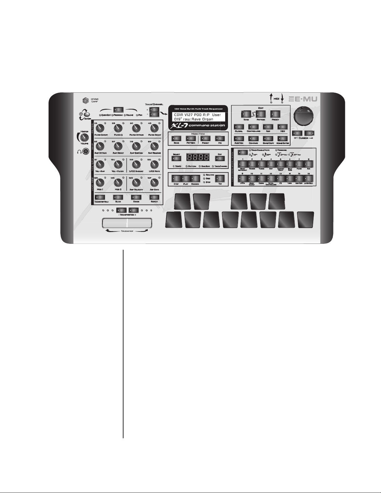
Basic Operations
Basic Operations
The XL-7 front panel contains an LCD screen, 13 velocity & pressure
sensitive performance pads, a bi-directional touchstrip, 49 buttons, and 16
real-time controller knobs. Functions are grouped logically and the controls
are arranged for ease of use.
Power Switch The front panel On/Off switch is a “Soft” power switch that can be used to
turn power on and off when the XL-7 is rack mounted. Use the AC power
switch on the rear panel if you wish to completely disconnect XL-7 from
the AC mains.
The power switch incorporates a “fail-safe” feature when powering down.
Once the power down sequence has begun, you have five seconds to press
the power switch again and stop XL-7 from turning off.
Volume Control This control is the master volume control for all audio outputs. The Volume
Control does not affect any editing or user interface operations. The front
panel volume control is a digital attenuator. For maximum dynamic range,
turn this knob all the way up and control the volume from your mixer or
amplifier.
12VDC Lamp The BNC connector in the upper left corner of the XL-7 panel supplies 12
volts DC at 250 mA to power a standard mixing desk lamp. (Order E-MU
Model Number 7773 - Locking Lamp from your E-MU dealer.)
XL-7 Owners Manual 31
Page 44
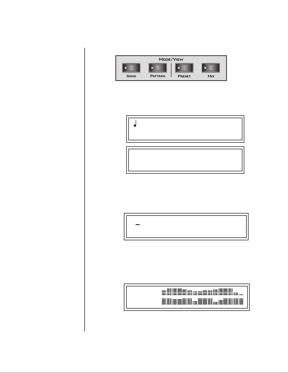
Mode/View Buttons
Basic Operations
Mode/View Buttons
The Song and Pattern buttons change both the mode and current display
view. Pressing Song or Pattern places the XL-7 in the selected mode.
Since Song and pattern are Mode buttons, the LEDs stay on when they have
been selected, even if Preset or Mix view buttons are activated.
An asterisk (*) appears in
the Pattern, Song or Preset
display to indicate that the item
needs to be saved.
Song Mode
Display
:100 M:04/4 Bar:001.1
000 256 bar blank
Pattern Mode
Display
The Preset button brings up the Preset/MIDI Channel selection screen
shown below. This important screen allows you to change the Preset,
Volume and Pan position for all 32 MIDI channels. The Preset button does
not change the Song or Pattern mode status and this screen can be edited
while a Pattern or Song is playing back.
Preset Select
Screen
The Mix button brings up a graphic display of the volume settings for all 32
MIDI channels. This is the same volume setting as in the Preset Select
screen except that all 32 MIDI channels can be simultaneously viewed and
edited. The Mix button does not change the Song or Pattern mode status
and this screen can be edited while a Pattern or Song is playing back.
T
01 STOP Ln:01 Bar: 01.1
1
009
C01 V127 P01
079
Smooth 6
3
bts: Logic
A:off USER
R
32 E-MU Systems
Mix Screen
CH VOLS
01A:125
To View the Pan Settings for all 32 Channels
1. Press the Home/Enter key (to move the cursor to “Home” position) and
turn the data entry control clockwise from the Mix screen.
Page 45
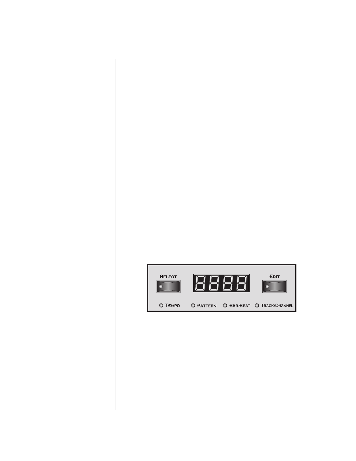
Basic Operations
LED View Select Section
Track/Channel +/Buttons
These very handy buttons, located to the left of the LCD, serve as a shortcut
to increment or decrement the Track (in Pattern mode), the MIDI Channel
(in Preset mode), Layer (in Preset Edit mode) or Step Numbers (in Arpeggiator Edit mode).
Data Entry Control The data entry control is a stepped, variable control switch used to change
parameter values. The wheel increments or decrements the current value
one unit with each click. This control incorporates acceleration, which
advances the value faster if the data entry control is turned quickly.
Left/Right Cursor Buttons
These buttons move the cursor to the next parameter on the display. (The
cursor is a little flashing line underneath one of the parameters in the
display.) Press either cursor button until the cursor is underneath the
desired parameter. The cursor buttons have an auto-repeat feature which
advances the cursor when the button is held continuously.
The cursor can be moved bidirectionally using the data entry control while
either cursor select button is held down (for example, press and hold the
right cursor button and turn the data entry control).
LED View
Select Section
OO
OO
Selecting patterns using
this method allows you to see
the current and next pattern
numbers.
The numeric LED display in the center of the XL-7 can display: Tempo,
Pattern Number, the current Bar/Beat, or the MIDI Channel. Repeatedly
pressing the Select button cycles through the four modes.
Pressing the Edit button lights its associated LED and allows you to edit the
displayed value using the data entry control. Pressing Edit again deactivates
this mode. To select a new pattern, you must exit Edit mode for the new
pattern to be selected.
By pressing and holding the Edit button, and then turning the data entry
control, the displayed parameter can be quickly edited without latching the
Edit mode on.
XL-7 Owners Manual 33
Page 46

Basic Operations
Sequencer Controls
Sequencer
These buttons control the sequencer transport functions.
Controls
Stop Button Pressing the Stop button immediately stops any currently playing Pattern
Sequence or Song Sequence. The sequence remains at its current location.
Press the Play button to resume from the current location.
Press the Stop button when the sequence is stopped to return to the
beginning of the sequence (RTZ). Pressing the Stop button a third time
reloads the initial setup information for the Pattern or Song.
Play Button The Play button engages the transport, regardless of sequencer mode
(except in step edit). The LED in the button will be illuminated when the
sequence is running.
Pressing Play while in Record mode puts the sequencer into Pause mode.
The sequencer stops and the Play LED flashes. Pressing Play again resumes
Record mode.
Record Button The Record button selects one of the three Pattern record modes or two
Song record modes.
Song Record modes (from Song mode)
• One press .............. Realtime record mode
• Two presses........... Step record mode
Pattern Record modes (from Pattern mode)
• One press .............. Realtime record mode
• Two presses........... Grid record mode
• Three presses ........ Step record mode
OO
OO
While a pattern is
playing, press and hold the Play
button and press Record to
jump into Grid Edit mode.
The LEDs to the right of the button indicate the record mode. After
selecting a record mode, the Play button LED will be flashing. Press Play to
begin recording.
You can press Record at any time during recording or playback to go in and
out of Realtime Record mode (i.e. Punch In & Out)
Tap Tempo The Tap Tempo button allows you to change the tempo at any time by
tapping the button at the desired tempo. Three taps are initially required to
change the tempo and then the tempo follows with each subsequent tap.
34 E-MU Systems
Page 47

Basic Operations
Edit Section
Edit Section
Song Edit Button The Song Edit menu allows you to name and edit songs. An illuminated
LED in the button indicates that you are in Song Edit mode. For more information about Songs and Song mode, see page 94. When pressed in combination with the Pattern Edit button, Song Edit puts the XL-7 in Demo
mode.
Pattern Edit Button The Pattern Edit menu allows you to name and edit patterns. An illumi-
nated LED in the button indicates that you are in Pattern Edit mode. For
more information about Patterns and Pattern Editing, see page 54. When
pressed in combination with the Song Edit button, this button puts XL-7 in
Demo mode.
Preset Edit Button The Preset Edit menu allows you to create and edit presets. An illuminated
LED in the button indicates that you are in Preset Edit mode. For more
information about the Preset Edit menu, see page 183.
Global Button The Global menu contains parameters that affect the entire machine. An
illuminated LED in the button indicates that you are in the Global menu.
For more information about the Global menu, see page 129
Controllers Button The Controllers menu contains parameters that are related to the front
panel controller knob and button triggers. An illuminated LED in the
button indicates that you are in the Controllers menu. For more information about the Controllers menu, see page 119.
XL-7 Owners Manual 35
Page 48

Basic Operations
Edit Section
Arpeggiator Button The Arpeggiator menu contains parameters that are related to the Master
Arpeggiator such as creating and editing arpeggiator patterns. An illuminated LED in the button indicates that you are in the Arpeggiator menu.
For more information about the Arpeggiator menu, see page 227
MIDI Button The MIDI menu contains parameters that are MIDI related. An illuminated
LED in the button indicates that you are in the MIDI menu. For more information about the MIDI menu, see page 143.
MIDI Panic Button Pressing the MIDI and Home/Enter buttons simultaneously sends a MIDI
“All Notes Off” and “All Sound Off” for all 32 MIDI channels.
Home/Enter Button The Home/Enter button is dual purpose. In general, this button acts as the
“Home” button. For example, when in an Edit menu, this button snaps the
cursor to the page name field of the current screen. When viewing the
Preset Select screen, this button snaps the cursor to the preset number field.
The flashing green LED of the Home/Enter button indicates that pressing
the button will initiate a particular operation.
Save/Copy Button The Save/Copy button is used to save changes to a pattern, song, preset,
copy data between presets, randomize presets and to move other types of
data. Selected groups of parameters, such as PatchCord settings, can be
copied between Presets and/or between Layers using this menu. The menu
is context-sensitive and will start at the appropriate save screen. See Save/
Copy on page 269 for more information.
The LED in the button illuminates to indicate that you are in the Save/
Copy menu. The LED also illuminates when any preset parameter has been
changed in the Edit menu (or if the front panel knobs have been moved
with Quick-Edit mode enabled).
Compare Button The Compare button allows you to toggle between an edited version of a
preset and the original, unedited version. When a preset has been edited,
an asterisk appears in the preset name field and the Save/Copy LED flashes.
Press the Compare button, lighting it’s LED, to hear the unedited preset.
Press the Compare button again to hear the edited preset. If edits are made
to the preset while listening to the compared original version, compare
mode is aborted and the compare LED goes off.
Audition Button When the Audition button is pressed, the LED next to the button will
illuminate and a short “Riff” (programmed as part of the preset) will play.
The Riff is latched on and plays continuously until the button is pressed
again. Presets can be changed while Audition is latched on. See “Bank Select
Commands” on page 180 for more information on selecting banks via MIDI.
36 E-MU Systems
Page 49

Basic Operations
Real-time Controller Knobs
The top line of the Preset display changes to show the MIDI Bank Select
controller values needed to select the preset being auditioned. This handy
feature lets you know the exact Bank and Preset number.
Real-time
Controller
Knobs
MSB
Bank MSB:007 LSB:3
Preset #
The Real-time Controller Knobs can serve several purposes. The first four
functions are selected using the Controller Function Select button above
the realtime control knobs. Preset Quick Edit can be enabled to use the
knobs for editing in the Preset Edit menu.
1. Quick Edit - Real-time control of internal synthesizer parameters and
“Quick Editing” the initial settings of the real-time controllers
2. Programmable Knobs - Real-time control of MIDI continuous
controllers on external synthesizers
3. Volume - Setting the volume of 16 channels.
4. Pan - Setting the pan position of 16 channels.
0
823 bts: Kraftwork
Controller Function Select
LSB
XL-7
XL-7 Owners Manual 37
Page 50

Knob Functions Quick Edit mode
The Real-time controller knobs provide direct control of the XL-7’s synthesizer parameters when the Controller Function Select is set to Quick Edit.
There is an LED next to each of the control knobs which illuminates to
indicate that the knob setting has been changed from the value
programmed in the preset (“Knobs Preset Quick Edit” mode must be
enabled in the Controllers menu). If the knob position is returned to the
original setting, the LED is extinguished.
OO
OO
Quick Edit knob
movements can be recorded into
the sequencer using realtime
song or pattern record modes.
Initial controller values can be stored in every preset. When you move a
knob with Quick-Edit enabled, the Initial Controller Value is updated with
the knob’s new value. The knob’s LED lights indicating that the preset value
has been changed. The MIDI A-P values are stored in the corresponding
Initial Controller Amount parameter in the Preset Edit menu (see “Initial
Controller Amount” on page 221). The Save/Copy button LED flashes to
remind you that the preset has been edited. “Quick-Edits” made to a preset
are lost if you select another preset before saving them.
The four rows of knobs always control the preset on the basic MIDI channel
(the channel showing on the preset select screen), when the control switch
is set to Quick Edit.
Basic Operations
Real-time Controller Knobs
The labels (Filter Cutoff, Filter Q, Filter Attack, Filter Decay, etc.) printed on
these rows show how the factory ROM presets are programmed to respond.
(The controls may not exactly conform to the front panel labels depending on the
preset.) You can change the way a preset responds to MIDI A-P messages
from the Preset Edit menu (PatchCords). The knobs only generate a
message when you move a knob to a new value. The current value jumps to
the new value.
To Quick-Edit a Preset
1. Select Quick Edit mode using the Controller Function Select button.
2. Use the Control Knobs to change the sound of the current preset as
desired. An asterisk (*) appears in the preset view display indicating that
the preset has been modified.
3. Press the Save/Copy button. You may have to turn the data entry
control so that the display reads, “Save PRESET to.”
4. Press the right cursor button to select the bottom row.
5. Optional: Select a new preset location if you don’t want to overwrite
the current preset, or if the current preset is a ROM preset.
6. Press the Enter button to save the preset.
38 E-MU Systems
Page 51

OO
OO
Turning a knob while in
this screen automatically selects
that knob for programming!
Basic Operations
Real-time Controller Knobs
Programmable Knobs mode
If the “Programmable Knobs” parameter in the Controllers menu is set to
“Ext,” or “Both,” the system sends MIDI controller messages when you turn
the Controller knobs. Each knob can be programmed to send on any MIDI
channel (01A-16B) and on any continuous controller number from 1-95.
The knobs only generate a message when you move a knob to a new value.
The Controller Knob LEDs always remain off in this mode. See “Programmable Knobs” on page 125.
To Program the Programmable Knobs
1. Press the Controllers button. Its LED will illuminate.
2. Turn the data entry control to select the Programmable Knobs screen.
Knob #
K1 PROGRAMMABLE KNOBS
Ctrl: 22 Ch:01A Ext
CC#
3. Use the left/right cursor controls to select the fields.
4. Select the MIDI Continuous Controller number, the MIDI channel, and
Internal/External or Both for each of the 16 knobs.
5. Save the Multisetup if you want to save these settings. See page 131.
Multichannel Volume Knobs
In this mode, each of the 16 knobs will control MIDI Channel Volume for
the like-numbered channel. This directly edits the value shown on the
preset select screen and is equivalent to sending MIDI cc#7.
MIDI Chan Int/Ext/Both/Seq
CH VOLS
01A:098
View Mode must be set to “MIX” in order to see the display shown above.
When “Knobs MIDI Out” in the MIDI menu is enabled, any knob change
will send MIDI cc#7 to the MIDI out port as well as controlling the internal
channel volume.
In this mode, the LEDs next to the sixteen knobs blink to indicate MIDI
activity on the same numbered MIDI channel (from the keypads, sequencer
or external MIDI sources).
XL-7 Owners Manual 39
Page 52

Basic Operations
Real-time Controller Knobs
Multichannel Pan Knobs
In this mode, each of the 16 knobs will control MIDI Channel Pan for the
like-numbered channel.This directly edits the value shown on the preset
select screen and is equivalent to sending MIDI cc#10.
CH PANS
01A:56
View Mode must be set to “MIX” in order to see the display shown above.
When “Knobs MIDI Out” in the MIDI menu is enabled, any knob change
will send MIDI cc#10 to the MIDI out port as well as controlling the
internal channel volume.
In this mode, the LEDs next to the sixteen knobs blink to indicate MIDI
activity on the same numbered MIDI channel (from the keypads, sequencer
or external MIDI sources).
R
40 E-MU Systems
Page 53

Basic Operations
Trigger Buttons
Trigger
Buttons
OO
OO
Trigger button
presses can be recorded into
patterns and songs.
The trigger button section serves multiple purposes which are listed below.
• Assignable & latchable note triggers. See page 124.
• Sequencer track select buttons See page 22 and page 54.
• Sequencer grid edit entry keys. See page 63.
• Preset Edit menu jump keys. See below.
Mode Switch
The mode switch is normally used to select between Triggers and Track
Select/Mute. In Sequencer Grid Edit, the mode switch is used to select step
resolution.
Trigger Mode Select Triggers mode by pressing the mode select button so that the
“Triggers” LED is illuminated. Now the 16 buttons work like keyboard
notes. Each of the 16 buttons can be assigned to any MIDI note, on any
MIDI Channel (01A-16B), with any velocity (0-127), and can be set to be
latched or momentarily on. Latched note will hold until the button is
pressed again. Latched notes will be indicated by the LEDs. When Beats
mode is selected, the Trigger Keys are used to enable or mute Beats Parts.
Trigger keys are assigned from the Controllers menu. See page 124 for more
information.
Preset Menu Jump Keys
Whenever you are in the Preset Edit menu, the sixteen command buttons
function as “jump” buttons to the various screens in the Preset Edit menu.
The jump location is labelled directly below each button.
Pressing a jump button instantly takes you to the first screen in the selected
category. Pressing the button again takes you to the second screen in the
category and so on. Repeated pressing will rotate you back to the first
screen in the category.
XL-7 Owners Manual 41
Page 54
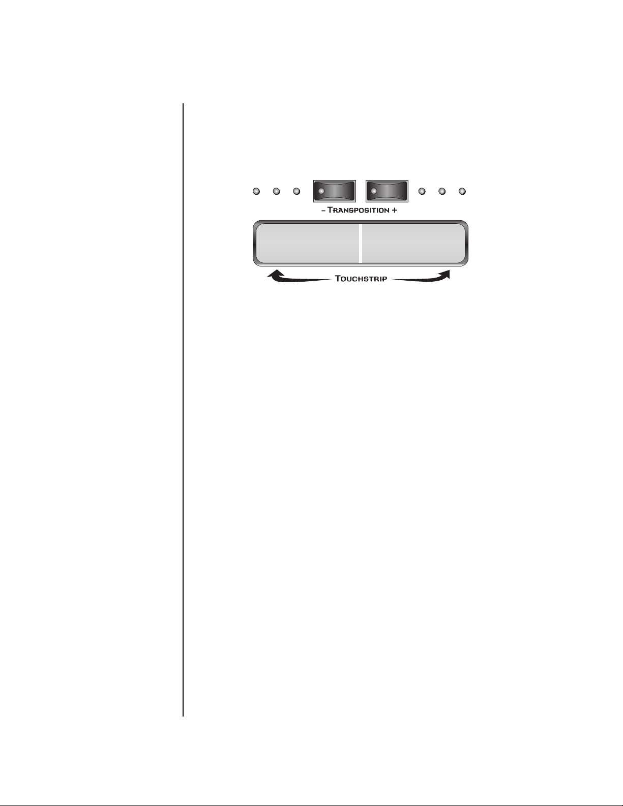
Basic Operations
Touchstrip, Transpose, Keypads & Glide
Touchstrip,
Transpose,
Keypads &
The Touchstrip is a bi-directional controller which is normally connected to
control pitch. It can, however, be patched in to any modulation destination
in the Cords section of the Preset Edit menu. The Touchstrip is referred to
and programmed as “Pitch Wheel” in the Cords menu. See page 211.
Glide
Simply slide your finger along the touchstrip while playing the keypads to
hear pitch bend. There is a slight “dead band” in the very center of the strip
to facilitate starting on pitch. You can press anywhere along the strip and
the pitch will instantly jump to that setting. When you release your finger,
the pitch will jump back to normal.
Touchstrip Hold The Touchstrip Hold button holds the pitch at the position last touched so
that it doesn’t jump back to center when released. The LED in the button
illuminates when this function is on.
Transpose Buttons These buttons transpose the current range of the rubber keyboard up and
down in one octave intervals. The LEDs on either side of the transpose
buttons show the currently selected range. With no LEDs illuminated, the
keyboard is in its normal range, Middle C to High C (60-72). Each LED to
the right of the buttons stands for one octave up. Each LED to the left of
the buttons stands for one octave down.
Rubber Keypads The velocity and pressure-sensitive keypads can play on any MIDI channel
as programmed in the Controllers menu. They are normally set to play on
the “Basic” channel, which means that they play the preset currently
showing in the preset view screen. The keypads output channel (mono)
pressure internally (routed in the PatchCords) and both channel and
polyphonic pressure over MIDI.
Glide Button This button turns Glide (portamento) on or off for the current preset. The
LED in the button illuminates when Glide is on. See Glide on page 201.
42 E-MU Systems
Page 55

Basic Operations
Touchstrip, Transpose, Keypads & Glide
Erase Button When this button is latched on (LED illuminated) while recording a
pattern, any note played on the keyboard will remove that note from the
pattern as long as the keyboard key is held down. This allows you to
quickly removed any “flubbed” notes without having to enter Pattern Edit
mode.
In Grid record mode, pressing the Erase button while the cursor is on one of
the grid locations, removes the note from that location.
In Song step record mode, pressing the Erase button erases the currently
selected step from the song.
Repeat Button When this button is latched on (LED illuminated) while recording a
pattern, played notes will repeat at the current pattern quantize setting
(page 55). You can get some great effects with this feature by simultaneously changing the volume or pitch as the sound repeats.
In Song step edit mode, the Repeat button functions as a “Pattern Insert”
button. See page 95 for more information.
XL-7 Owners Manual 43
Page 56

Basic Operations
Preset Screen
Preset Screen The Preset Select screen is accessed by pressing the Preset View button
located directly under the LCD. From this screen you can examine or
change the Preset, Volume, Pan Position and Preset Location for each of the
32 MIDI channels.
C01A V127 P01
0793 kit: Hide & Seek
MIDI Channel Selection
To Change the MIDI Channel
1. Press the Preset View button to display the Preset Select screen.
2. Press the Track/Channel inc/dec buttons located to the left of the liquid
crystal display to select channels 01A through 16B. The preset, volume
and pan settings for each channel will be displayed as you scroll
through the channels.
The channel number shown in the main screen is the “basic MIDI channel”
when in Omni or Poly modes.
Preset Selection To Change the Preset
1. Press the Preset View button to display the Preset Select screen.
2. Press either cursor key until the cursor is underneath the preset
Bank Contents
0
128 RAM Presets
1
128 RAM Presets
2
128 RAM Presets
USERROM 1
3
128 RAM Presets
0
128 ROM Presets
1
128 ROM Presets
2
128 ROM Presets
??
Depending on
ROM sets installed
number. (The cursor is a little flashing line underneath one of the
parameters in the display.) As you rotate the data entry control, the
preset number and name changes.
3. The displayed preset is assigned to the displayed MIDI channel. Presets
are arranged into banks of 128, as shown in the diagram at left.
Bank Number
Preset
Number
C01A V127 P01
0793 bts: Logic
A:off User
R
A:off User
R
*
An asterisk in the
preset view screen indicates
that the preset has been
modified.
(Change the preset without
saving to remove the
asterisk.)
44 E-MU Systems
*
Indicates that the
preset was modified
Using the screen above as an example, the superscripted number 2 in the
second line of the display identifies the current bank number.
• Select banks independently of the of the preset number by locating the
cursor on the Bank field and turning the data entry control.
Page 57

MIDI BANK SELECT
MSB LSB
cc00 cc32
Basic Operations
Preset Screen
USER
USER
USER
USER
XL-7
XL-7
XL-7
XL-7
This chart shows the MSB and LSB numbers needed to select preset banks over MIDI.
Select a bank, then send the program change number. Without a bank select command,
presets are selected from within the current bank.
00
00
00
00
14
14
14
14
00
01
02
03
00
01
02
03
Bank 0
Bank 1
Bank 2
Bank 3
Bank 0
Bank 1
Bank 2
Bank 3
Channel Volume Channel Volume sets the volume of the selected MIDI channel in relation
to the other channels. This is the same parameter as MIDI volume control
#7, and changes made over MIDI are shown in the display.
Volume
C01 V127 P01
A:off User
R
0793 bts: Logic
To Change the Channel Volume
1. Press the Preset View button to display the Preset Select screen.
2. Press either cursor key until the cursor is underneath the volume value.
3. Rotate the data entry control to select a volume level. The Channel
Volume range is 000-127.
XL-7 Owners Manual 45
Page 58

Basic Operations
Preset Screen
Channel Pan Channel Pan sets the stereo position of the selected MIDI channel. This
control operates like the balance control on your home stereo system.
Channel Pan is the same parameter as MIDI pan controller #10, and
changes made over MIDI are shown in the display.
Pan Position
C01 V127 P01R A:off User
0793 bts: Logic
Note: Pan settings in the preset ADD algebraically with the Channel Pan
setting. Therefore, if the pan setting in the preset were set to “63
the Channel Pan setting full left would return the sound to the center
position.
To Change the Channel Pan
1. Press the Preset View button to display the Preset Select screen.
2. Press either cursor key until the cursor is underneath the pan field.
3. Rotate the data entry control to select a pan value. 64L indicates a hard
left pan, 63R indicates a hard right pan. With a setting of “00,” the
sound is centered in the stereo field.
R,” moving
Channel Arpeggiator This function controls the arpeggiator for each MIDI channel. When the
channel arpeggiator mode is set to Off, then there is no arpeggiation on
that channel, regardless of what is set up in the Master Arpeggiator or
preset. If the channel arpeggiator is On, the preset’s arpeggiator is used,
regardless of whether or not it is turned on in the Preset Edit menu. This
lets you turn on arpeggiation from the main screen.
If the mode is set to “P” (for preset), the preset’s arpeggiator settings and
on/off status is used. If the mode is set to “M” (for master), the master
arpeggiator settings and on/off status (located in the Arp menu) are used.
See the “Arpeggiator/Beats Menu” on page 227 for more information.
To Play the Arpeggiator (Quick Start)
1. From the Preset View screen, press either cursor key repeatedly until
the cursor is underneath the arpeggiator field (A:).
2. Rotate the data entry control to select “P” for preset.
3. Press either cursor key repeatedly until the cursor is underneath the
Preset Category field and select “arp:” using the data entry control.
4. Press the right cursor button to move it to the Preset Name field.
5. Play notes or chords on the keyboard. Change presets as desired to
audition the various patterns and presets.
46 E-MU Systems
Page 59
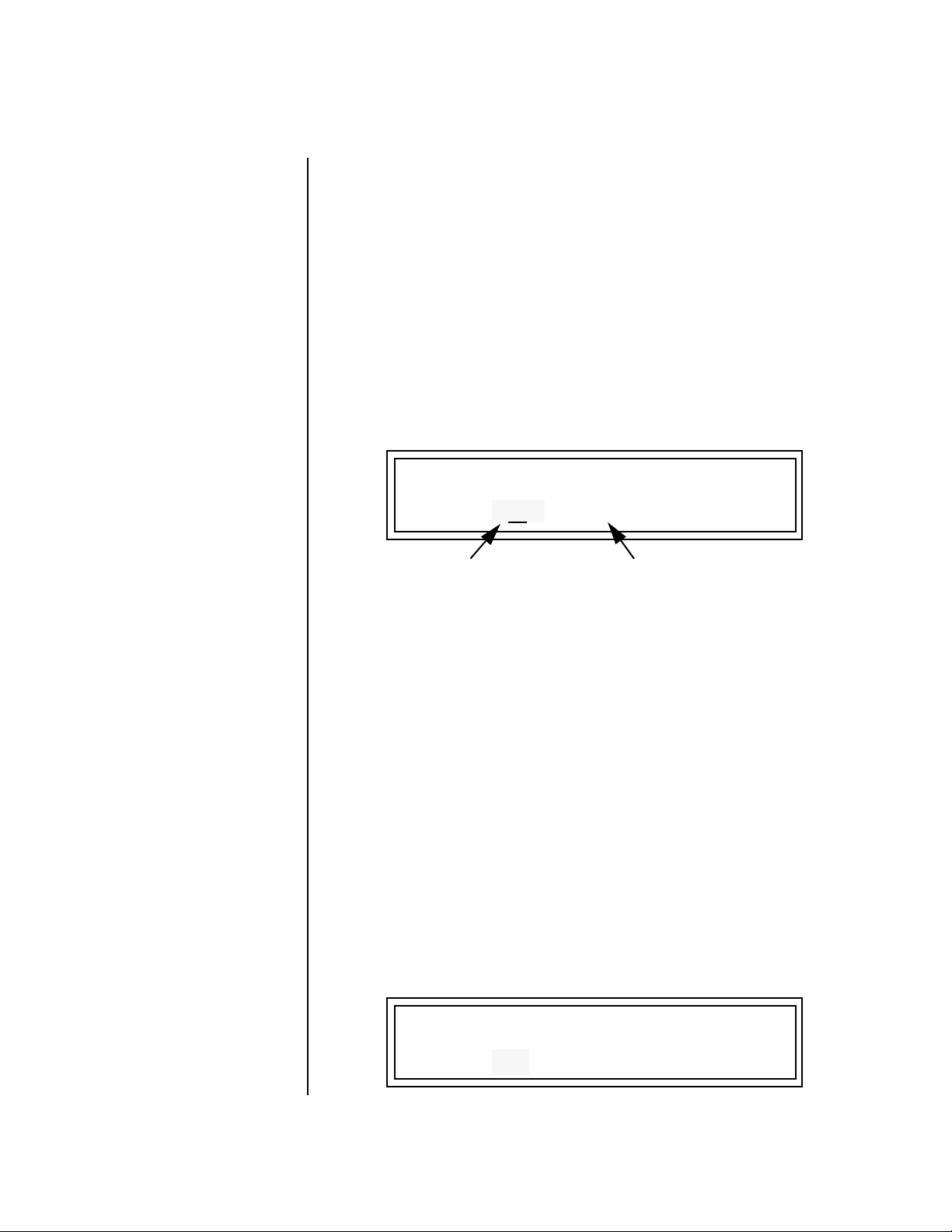
Basic Operations
Sound Navigator
Sound
Navigator
Sound Navigator allows you to search through preset and instrument
categories to find the type of sound you’re looking for. Each preset and
instrument has a name and a three letter preset category. You can create
your own categories in order to group favorite presets. The preset category
is assigned in the Preset Edit menu (Preset Name). Instrument categories are
fixed.
Preset Category When you want to find presets in a particular category, you simply change
the category field in the Preset View screen, then move the cursor to the
preset name field to scroll through all the presets in the selected category.
When the cursor is on the Preset Category field, turning the data entry
control selects different preset categories. The Name Field will change to
show the first preset in each category.
C01 V127 P00
A:off User
0641 w al: Raverotic
Preset Category
To Change the Preset Category
1. From the Preset View screen (shown above), press either cursor key
repeatedly until the cursor is underneath the preset category field.
2. Rotate the data entry control to select one of the preset categories.
Preset Categories are displayed in alphabetical order.
Preset Name
To Select a Preset within a Category
1. After selecting a category, move the cursor to the Preset Name field.
2. Rotate the data entry control to scroll through the presets in the
selected category. Note that the preset numbers will no longer change
sequentially.
Instrument Category When the cursor is on the Instrument Category field (Preset Edit menu),
turning the data entry control selects different instrument categories. The
Name Field changes to show the first instrument in each category. Move
the cursor back to the instrument name to choose other instruments in the
selected category.
L1
INSTRUMENT ROM:XL-7
0641 wal: Raverotic
XL-7 Owners Manual 47
Page 60

Basic Operations
Sound Navigator
48 E-MU Systems
Page 61

__
__
Warning: Sequencer
Patterns and Songs are NOT
saved until you save them in the
Save/Copy menu.
Sequencer
The XL-7 Sequencer is an extremely powerful, yet easy to use MIDI
recording device. Several different methods of creating and editing
sequences are provided to suit your personal style of composition.
To Enable the Sequencer
XL-7 always powers up in pattern mode. Pattern mode can be selected from
any other screen by pressing the Pattern mode button below the LCD.
A Pattern can be immediately started by pressing the Play button. Press the
Song mode button to select Song mode.
To Select a Song or Pattern
With the XL-7 in Song mode and the cursor in the Home position, turn the
data entry control to select a new song.
With the XL-7 in Pattern mode and the cursor in the Home position, turn
the data entry control to select a new pattern.
An asterisk (*) appears in the
Pattern or Song display to
indicate that the item needs to
be saved. The Save/Copy button
LED will also be flashing to
remind you.
To Edit a Pattern
Select the pattern you wish to edit, then press the Pattern Edit button. Turn
the data entry control to scroll through the Pattern Edit menu items.
See page 70.
To Edit a Song
Select the song you wish to edit, then press the Song Edit button. Turn the
data entry control to scroll through the song edit menus. See page 99.
XL-7 Owners Manual 49
Page 62

Sequencer
Overview
Overview XL-7’s sequencer is a Song/Pattern based recorder featuring high resolution
recording at 384 ticks per beat. Multiple record modes - Song, Pattern, Grid,
Step & Realtime Record allow you ultimate flexibility in the way you
compose you music. You can add, monitor and modify parts on the fly or
switch recording modes without stopping. The sequencer features 16 tracks,
each of which can record up to 16 channels. Automated mixing and synth
control is a snap. Read on and discover just how easy recording can be.
Definitions The various components of XL-7 sequences are described below, starting
from the smallest units “events” and ending with the largest element, a
“song”. Songs can be up to 999 bars in length.
Events Events are the smallest bits of information that are recorded into a
sequencer. Note-on, note-off, continuous controller messages, MIDI clocks,
and program change commands are all events.
Tracks Tracks are groups of events that will be assigned to a specific MIDI channel
for playback. A single track can be assigned to one or two MIDI channels
(one normal, one aux). A track can play internally only, externally only,
both internally and externally, or not assigned at all. See page 86.
Tracks may also contain information encoded on multiple MIDI channels.
XL-7 can assign these multichannel events to play on their assigned MIDI
channels or it can force them all to a new assigned channel. See page 86.
Individual tracks can be muted on playback. The sequencer supports 16
tracks (T1 - T16).
Patterns Patterns are collections of tracks and are the basic unit of storage for
sequences. You cannot save a track unless it is part of a pattern.
Patterns can be up to 32 bars in length. After playing to the end of its
specified length, a pattern will loop back to the start. Looping repeats
indefinitely as long as the sequencer is running.
Patterns store the following information in non-volatile Flash memory
which is recalled just before the pattern is played.
__
__
Important: Pattern
Setup information is saved as it
was set at the moment you
saved the pattern.
• Pattern Name & Number
• Track Events
• Initial Tempo & Meter
• Master FX setup
• Track to MIDI Channel mapping....
• Track Mutes .....................................
• Bank/Program changes....................
• Volume & Pan settings....................
• Mix Output setup............................
• Arp Status (off, on, preset, master)..
These parameters are
stored for each track
used in the pattern.
50 E-MU Systems
Page 63

Press Once
OO
Press Twice
Sequencer
Definitions
Pattern Recording & Editing
Patterns can be edited in three ways:
• Realtime Record - Events are stored in the designated track as they are
played on the keypad or from the MIDI input port. Events are overdubbed into the track as the track plays and loops. The original channel
of each event is maintained when recorded.
Individual events can be erased by pressing the realtime erase button
and re-playing the event during the time that the event occurs in the
pattern.
• Grid Editing - In this mode, the sixteen trigger buttons become a time
grid. A note event is first selected and is then placed at any time location
by pressing the appropriate grid button.
The grid resolution can be changed to allow a whole measure or a fraction of a measure to be displayed on the button grid.
Press 3 Times
Asterisk
Appears
Pressing Rec
List Edit
(press enter)
Executing
an Edit
function
OO
Use the “Revert to
Saved Pattern” feature to
remove the asterisk and discard
your pattern edits. See page 93
for more information.
No
Asterisk
Changing:
tempo,
meter,
length,
name, chan.
asssign, etc.
• Step Edit - In this mode, you can single-step through the time locations
(bars, beats, & ticks) and place events anywhere you want.
The play button jumps from the current location to the next note value
as determined by the resolution setting.
The Asterisk
When a pattern (or song) has been edited and needs to be saved an asterisk
(*) appears in the display. The Save/Copy LED will also be flashing as a
reminder to save your work. The asterisk and your edits remain in the
single edit buffer even if you change patterns. Edits are only erased by
saving the pattern, editing another pattern, invoking the “Revert To Saved”
feature, or turning the unit off. Saving saves the current pattern and NOT
the edit buffer.
T
01 STOP Ln: 08 Bar: 01 . 1
0
000
Start of IT
*
Indicates that the Pattern
needs to be saved.
Standard MIDI Files
Patterns can also be imported from a Standard MIDI File (SMF) dump. SMF
type 0 files are imported with MIDI channels 1-16 going to the same
numbered XL-7 track. SMF type 1 files are imported with tracks 1-16 going
to the same numbered XL-7 track. Tracks 17 and above will not be imported
into XL-7.
XL-7 Owners Manual 51
Page 64

Sequencer
Definitions
Songs Songs are recorded on a single track which allows you to record Pattern Play
messages as well as real-time note and controller information. This lets you
link previously recorded patterns together to form more intricate arrangements, then overdub controller information such as volume, pan or other
controller information or additional note information. You can change
pattern length and track mutes in song mode without affecting your stored
patterns.
Song mode is also useful when you wish to record, playback or import a
sequence longer than 32 bars. For example, you could import a long multichannel sequence created on another sequencer as an XL-7 song.
Press Once
Press Twice
…as set
when the
Song was
The Song Track contains Pattern Play events as well as real-time data (note-on/off, continuous
saved
tempo
preset
volume
pan
mix
arp
FX
Note
data
The Song Track
Controller
data
Pattern 032 Pattern 002 Pattern 204
Pattern
play/mutes
controllers and other MIDI data).
Pattern
play/mutes
Note
data
Pattern
play/mutes
Note
data
End
Song Record Modes
• Realtime Record - Events are stored as they are played on the keypad,
controllers or from the MIDI input port as the single realtime track
plays. The original channel of each event is maintained when recorded.
• Step Edit - In this mode, you can single-step through the bar locations
and place Pattern Inserts wherever you want.
Songs store the following information in non-volatile Flash memory:
• Song Name & Number
• Realtime note & controller information
• Track Mutes for each Pattern Play event (these can be different than the
mutes stored in each Pattern.)
The 16 tracks of a song
can be assigned to either the A
or B channels using the “Song
Channel Assign” function on
page 110.
52 E-MU Systems
The following events are also saved as they were set when the Song was
saved. The “Event Source” option in the Song Edit menu (page 99) deter-
mines whether song or pattern events will be used in the song.
• Initial Tempo
• Master FX setup
• Event Source
• Volume ...................................................
• Pan..........................................................
• Mix Output setup...................................
• Arp channel status (off/on/preset/master)
These parameters are
stored for each channel
used in the song.
Page 65

Sequencer
Event Timing
Event Timing The following information is intended for advanced users. If you are just
getting started with XL-7 you can skip this section for now.
Songs and patterns both contain pre-sequence setup information that is
loaded just before a song or sequence plays. This pre-sequence information
is not reloaded when a pattern loops. Reloading this setup information
each time a pattern looped would cause data clogging and possible timing
errors in the sequence.
• The first two ticks (0 & 1) are reserved for pre-sequence setup information. Tick 0 is reserved for the internal pre-sequence setup information.
Tick 1 is used to place your own pre-sequence setup information so
that it won’t loop and cause timing errors.
• Events (controller data, program changes, sysex, etc.) are played before
Notes, even if they are located on the same numbered Tick. This is done
so that volume changes and other programming information will be in
place when the notes turn on.
When a track is set to "ext" (external transmit only), you will be allowed
to see the tick 0 spot for EVENTS. This allows you to remove any presequence setup data (which is stored at Tick 0) left over from when the
track may have been internal or both.
Events
tick 0
tick 1
Notes
Pattern/Song Setup Info
Reserved for User Events
Pre-Sequence
Setup Info
tick 0
tick 1
tick 2
Loop
tick 2
tick 3
tick 3
This chart shows how notes and other MIDI events are recorded at the beginning of a
pattern or song.
Notes are played after other MIDI events. Ticks 0 and 1 are reserved for pre-sequence
setup information which does not loop. Beginning at tick 2 of the pattern or song,
information is recorded normally (events first, then notes).
Track Priority
The XL-7sequencer handles lower numbered tracks first. Therefore, you
should put your most timing-critical data on low numbered tracks.
Normally this will not be important since the sequencer timing is so good,
but if you create very dense sequences, this information might be useful.
XL-7 Owners Manual 53
Page 66

Sequencer
Pattern Mode
Pattern Mode Pattern mode is selected by pressing the Pattern mode button beneath the
liquid crystal display. The screen shown below is displayed in Pattern mode
when the sequencer is stopped.
T
01 STOP Ln: 08 Bar: 01 . 1
0
000
Pattern Play Pressing Play in Pattern mode causes the selected pattern to
continuously play and loop. The display changes as shown.
Start of IT
T
01 STOP Ln:08 Bar:01 .1
0
CurPat: 002
NextPat: 0020
L.E.D. Beat Markers
• The Tap Tempo LED stays on
slightly longer at each bar.
• The Tap Tempo LED flashes to
mark each quarter note.
The Track Mute buttons can be used to select specific tracks for playback.
The track mute settings are saved when the pattern is saved and restored
when the pattern is run.
Pressing the Stop button stops the pattern immediately. Pressing
Stop again rewinds the pattern to the beginning (RTZ).
Pressing the Stop button a third time reloads the initial setup
information for the Pattern (or Song).
To select another pattern while one is already playing: Turn the data
entry control in Pattern Mode/View. The lower line of the display changes
to show the name and number of the pattern you have selected. The
Home/Enter LED will be flashing.
54 E-MU Systems
T
01 STOP Ln:08 Bar:01 .1
0
Club Luv
015
Page 67

Sequencer
Pattern Mode
Press Enter to jump to the new pattern when the current pattern ends. The
lower line of the display now again shows the current and next pattern
numbers.
T
01 STOP Ln:08 Bar:01 .1
0
CurPat: 002
To start a new pattern immediately, press Stop, select the new pattern
and press Play.
or… To select a pattern while playing, press Enter, press Stop, then Play.
NextPat: 0220
Realtime Recording As described on page 51, there are three ways to record patterns. Realtime
recording is the easiest way to begin recording. Notes and Controller events
are recorded into a pattern. External MIDI data can also be recorded.
Preparing to Record a Pattern
Before you record a pattern there are a few things you’ll want to set up.
Most of these steps apply to realtime or step recording.
• Erasing the pattern (if necessary).
• Program the Metronome (if necessary). Page 72.
• Define the pattern’s Time Signature and Pattern Length. Page 58.
• Setting the Count-in length (if necessary). Page 57.
• Setting Input Quantize (to correct timing errors in Realtime Recording,
to set the step rate in Step Recording, or to set the repeat rate when using
the front panel Repeat button). Page 55.
Select the desired Channel, Track and Preset for recording.
Input Quantize Input quantize corrects your timing and places notes exactly on the note
value of your choice. You can choose any of the following note values:
quarter notes, quarter note triplets, eighth notes, eighth note triplets,
sixteenth notes, sixteenth note triplets, thirty second notes, or thirty
second note triplets.
The illustration below shows one measure of 4/4 music (there are four
quarter notes, 8 eighth notes, and 16 sixteenth notes in a measure of 4/4).
1
4
1
8
1
16
XL-7 Owners Manual 55
Page 68

Sequencer
Pattern Mode
Suppose you wanted to record a bass drum beat on every quarter note. The
upper row of dots in the diagram below shows where you might have
played the four drum beats. The lower row of dots shows what happens
when Input Quantize is set to eighth note resolution. Each beat is now
moved to the nearest eighth note.
What you play
Beats fall on
Eighth Note Input Quantize
In the next example we’ll set Input Quantize to sixteenth note resolution.
In this example the beats you played have been assigned to the nearest
sixteenth note, which works on beats 3 & 4, but not on 1 & 2.
What you play
Beats fall on
Sixteenth Note Input Quantize
This brings up an important point.
Use the Lowest Quantization value needed.
If you’re recording a simple snare backbeat, there’s no point in using higher
quantization than eighth notes. To record something more complex, use a
finer resolution such as sixteenth or thirty-second notes.
You can change the Input Quantize setting in Pattern mode whether the
XL-7 is running or stopped, recording or not. You can also use different
resolutions on the same part. Use low resolution to record most of the part,
then switch to a finer resolution to add complexity.
Recording triplets is easy since there are four triplet modes (1/4t, 1/8t, 1/16t
and 1/32t). You can also switch between triplet and non-triplet modes to
record complex polyrhythms.
When Input Quantize is turned Off, you are recording in XL-7’s high
resolution mode in which beats can be placed on any one of 384 ticks per
measure. High resolution recording is great if you’re a good player and want
your performance captured as accurately as possible.
56 E-MU Systems
Page 69

Sequencer
Pattern Mode
To Set Input Quantize:
Input Quantize only works in Pattern mode.
1. Choose Pattern mode and select a Pattern.
2. Go into Record mode by pressing the Record button. The Pattern
Record screen shown below appears.
T
01 REC Ln: 08 Bar: 01. 1
Quan: 8 Met: on Cnt: 0
Note
Valu e
3. Choose the desired Input Quantize value using the data entry control.
4. Press Play to begin recording.
Count In The Count-in feature lets you hear the metronome for either one or two
measures before recording begins. This helps you get the feel of the beat
before you actually begin recording.
To set Count-in:
1. Choose Pattern mode and select a Pattern.
2. Go into Record mode by pressing the Record button. The Pattern
Record screen shown below appears.
T
01 REC Ln: 08 Bar: 01. 1
Quan: 8 Met: rec CntIn: 0
Count-inMetronome
3. Move the cursor underneath the Count-in (Cnt) field using cursor keys.
4. Select 0, 1, or 2 bars of count-in using the data entry control.
5. Press Play to begin recording.
XL-7 Owners Manual 57
Page 70

Sequencer
Pattern Mode
Pattern Length You can set the length of a pattern from 1 to 32 bars, either before, after or
even during recording.
To Set the Pattern Length from the Main Pattern Screen:
1. Select the pattern in Pattern mode.
2. Move the cursor to the Length (Ln) field using the cursor keys.
T
01 STOP Ln: 02 Bar: 01 . 1
0
000
3. Set the Length of the pattern using the data entry control.
Start of IT
Metronome The metronome is a timing aid when recording or playing back patterns
which produces an accented click on the first beat of each measure and a
softer click on other beats. This setting is NOT saved with the pattern.
To Set the Metronome:.
1. Go into Record mode by pressing the Record button.
2. Scroll to the Metronome screen using the data entry control.
3. Move the cursor underneath the Metronome field and set it to On, Off
or Rec using the data entry control. Set to On, the metronome plays
during recording and playback. Set to Rec, the metronome only plays
while recording.
4. The metronome value is set in the Pattern Edit menu. See page 72.
Recording a Pattern To Record a new Pattern:
1. Press the Pattern mode button. The screen shown below appears.
T
01 STOP Ln: 08 Bar: 01. 1
0
Start of IT
T
01 REC Ln: 08 Bar: 01. 1
For these instructions,
make sure Keyboard/Knob
Channel in the Controllers menu
is set to “Basic Channel”.
000
2. Select a Blank pattern to begin recording using the data entry control.
3. Press the Record button. The screen shown below appears.
Quan: 8 Met: on Cnt: 0
Auto-Correct Metronome on/off Count-in Bars
58 E-MU Systems
Pattern Length Current PositionTrack Number
Page 71

OO
OO
You can go in and out of
Record mode at any time by
pressing the Record button
Sequencer
Pattern Mode
4. Set the Pattern Length and Input Quantize value. For more infor-
mation on Input Quantize see page 55.
5. Set the number of count-in bars if you wish.
6. Select a Track number. The default value is Track one. This is fine for
the first track.
7. Press the Preset View button. The preset screen shown below appears.
C01A V127 P00 A:P User
3
050
8. Select a Preset for your first track.
9. Press the Preset View button again after you’ve selected a preset. The
LED will go out and you’ll be returned to the Pattern screen.
Get ready to record the first track!
10. Press Play to begin recording. Recording will begin after the count-in
period (if any). The pattern will loop when it reaches the end of its
length.
11. Press Stop when you’re finished recording.
kit:80’s Tones
OO
OO
To Erase an Entire
Pattern: Copy an “Empty
Sequence” over the pattern.
(Save/Copy menu).
Are you happy with your performance? If not, you can erase the track and
try again.
To Erase the Track:
12. Press the Pattern Edit button and turn the data entry control until you
find the “Cut Track to Clipboard” screen.
13. Move the cursor to the lower line of the display under Track 1.
14. Press the flashing Enter button to erase the track.
15. Press the Pattern Edit button again to exit the menu, then go back to
step 10 and re-record the track.
To Erase Specific Notes:
16. Press the Erase button in Realtime Record mode and hold down the
keyboard note you wish to erase. The note will be erased when it
comes around in the pattern.
To Record another Track:
17. Press the +Track button located to the left of the LCD. The track
number increments to Track 02.
18. Press the Preset View button. Notice that the MIDI channel has also
incremented to C02A. Select a preset.
19. Press the Preset View button again after you’ve selected a preset. You’ll
be returned to the Pattern screen.
XL-7 Owners Manual 59
Page 72

OO
OO
The Event Source
parameter (page 99) controls
how pattern settings are used in
Song mode.
Sequencer
Pattern Mode
20. Press the Stop button to return the beginning of the pattern.
21. Press Record, then Play to begin recording on track 2.
22. After recording track 2, check out the Track Enable buttons to mute
and un-mute the tracks.
23. A pattern must be SAVED or it will be erased when you change the
pattern. See “Save Pattern” on page 269.
You can continue to add up to 16 tracks. If you need more than this,
keep in mind that you can add up to 16 channels of data to each track!
Normally, it’s simpler to use just one channel per track.
• To setup a track for multichannel playback see “Channel Assign” on
page 86.
Saving Patterns
When you save a pattern (page 269), the following settings are also saved
(as set at the moment you saved). These setting are restored just before
pattern playback.
• Tempo & Meter
• Master FX setup (See page 136)
• Track to MIDI Channel mapping (See page 86)
• Track Mutes .....................................................
• Bank/Program changes....................................
• Initial Volume & Pan settings.........................
• Mix Output setup (See page 134) .....................
• Arp Status (off, on, preset, master).....................
These parameters
are stored for each
track used in the
pattern.
__
__
Too much controller
information can clog the
sequencer causing sluggish
performance and sloppy timing.
Use the “Thin Events” function
(page 76) to reduce the amount
of controller data in the pattern.
60 E-MU Systems
To Record Realtime Controller Data
You can mix and embellish your patterns by recording continuous
controllers along with note data.
1. Start by recording and saving a pattern.
Recording Quick Edits
The Quick Edit knobs are only active on the Basic Channel (the channel
currently displayed in the Preset View screen).
2. Select Quick Edit mode by pressing the Controller Function Select
button.
3. Select the channel with the preset you wish to Quick Edit.
4. Practice your knob movements before recording by Playing the
pattern and twisting the knobs.
5. When you’re ready to record, press Record while the sequencer is
playing (to punch-in), then perform the knob movements.
Page 73

Use the “Erase cc#
Events” function (page 77) to
erase controller data from the
pattern.
Sequencer
Pattern Mode
Record Multitrack Volume and Pan Information
You can record Volume and Pan information for all 16 channels simultaneously by using Volume Knob mode. You’ll be recording multichannel
volume or pan data onto a track. The default channel assignment will
rechannelize this data to a single channel. You must change this.
6. Select a track for the Realtime Controller data.
7. Press the Pattern Edit button and scroll to the “Channel Assign” page.
8. Set the track to MultiA. Now the track will record multichannel data.
9. Press the Pattern Edit button to exit the menu.
Automating the Volume of each Channel
10. Select Volume knob mode by repeatedly pressing the Controller
Function Select button (page 37).
11. Select Mix View mode if you wish to view the volume settings.
12. Press the Stop button twice to make sure the pattern starts at the
beginning.
13. Press the Record button in Pattern mode to get ready to realtime
record. The Play button LED will be flashing.
14. Press the Play button to begin recording. The controller knobs now
adjust the volumes of all 16 channels.
15. Press Stop when you’re finished recording.
Real-time Panning
16. Select Pan Knob mode by pressing the Controller Function Select
button.
17. Select Mix View mode by pressing the Mix button (if it’s not already
selected).
18. Turn the data entry control clockwise to select Ch Pan view.
19. Press the Stop button twice to make sure the pattern starts at the
beginning.
20. Press the Record button in Pattern mode to get ready to record. The
Play button LED will be flashing.
21. Press the Play button to begin recording. The controller knobs now
adjust the pan positions of all 16 tracks.
22. Press Stop when you’re finished recording.
XL-7 Owners Manual 61
Page 74

Sequencer
Pattern Mode
Erasing Controller Data
1. The Erase Events function (page 77) can be used to erase controller
data from a pattern.
2. Find the realtime controller number of the knob you wish to erase in
the Controllers menu.
(Volume is always cc#7, and Pan is always cc#10. The numbers of the 16
controller knobs can vary.)
3. Press the Pattern Edit button.
4. Scroll to Erase Events and move the cursor to the lower line of the
display.
5. Select the realtime controller number from step 2.
6. Press Enter to erase the controller data.
Using Realtime Repeat
When this button is latched on (LED illuminated) while recording a pattern
(or song), played notes will repeat at the current pattern quantize setting
(page 55). You can get some great effects with this feature by simultaneously changing the volume or pitch as the sound repeats.
1. Press the Record button once to go into Realtime Record mode.
2. Set the Input Quantize resolution on the LCD to the desired rate.
3. Press the Repeat button illuminating the LED.
4. Press Play to begin recording.
5. Play the Keypads (or keyboard). Notes now repeat according the Input
Quantize setting.
• You can change the Input Quantize setting at any time while recording.
Automatic Channel Assignment
Whenever you change a channel, the sequencer looks for a track that is
assigned to that channel. This feature automatically selects the proper track
in most cases, freeing you from having to think about it.
For your information, the algorithm works as follows:
1. If the current track is already assigned to this channel, or if this track is
a “multi” track containing this channel (i.e. MultiA if channel was set
to 07A) it does not change the current track.
2. If not, it starts at track 1 and looks for a track that is assigned to this
exact channel, and sets it to the first track that is.
3. If there wasn't one, again it starts at track 1 and looks for a “multi” track
that contains this channel, and sets it to the first track that does.
4. If none of the above succeed (meaning that this channel is not being
played on any track), it does not change the current track.
62 E-MU Systems
Also, changing the track in the list editors or channel assignment screens
sets the current track and vice versa.
Page 75
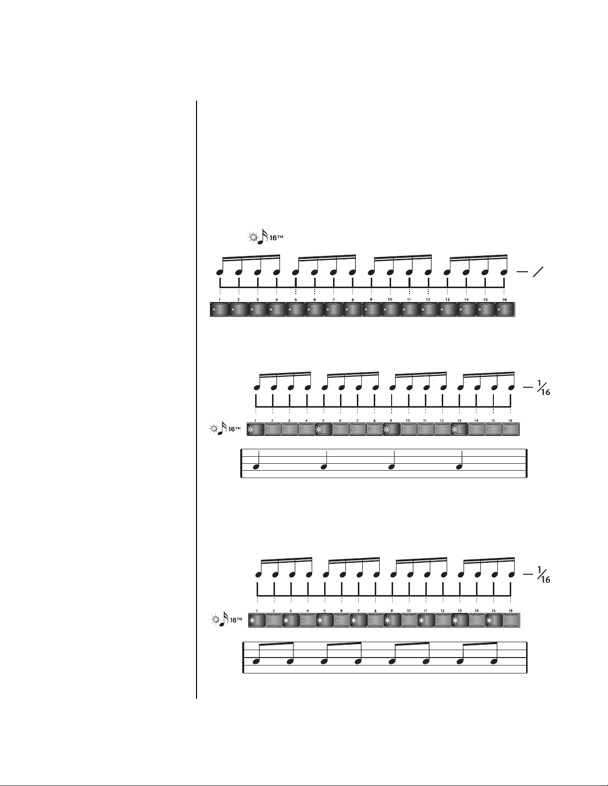
Sequencer
Pattern Mode
Grid Recording Grid recording allows you to lay out notes along a pre-defined grid. This is a
very visual way to lay down a beat and it makes it easy to experiment, since
you can change everything by just turning buttons on and off. XL-7 brings
a host of new features to the party.
What is Grid Recording?
Grid recording can be visualized as a series of notes placed along a line
where each note can be turned On or Off with a button. In the example
below, you’ll hear sixteen notes to a measure in 4/4 time.
1
16
To program quarter notes, you would turn on one note out of every four as
shown below.
Quarter Notes
Turning on every other button with the 16th note grid selected gives you
Eighth notes.
Eighth Notes
XL-7 Owners Manual 63
Page 76
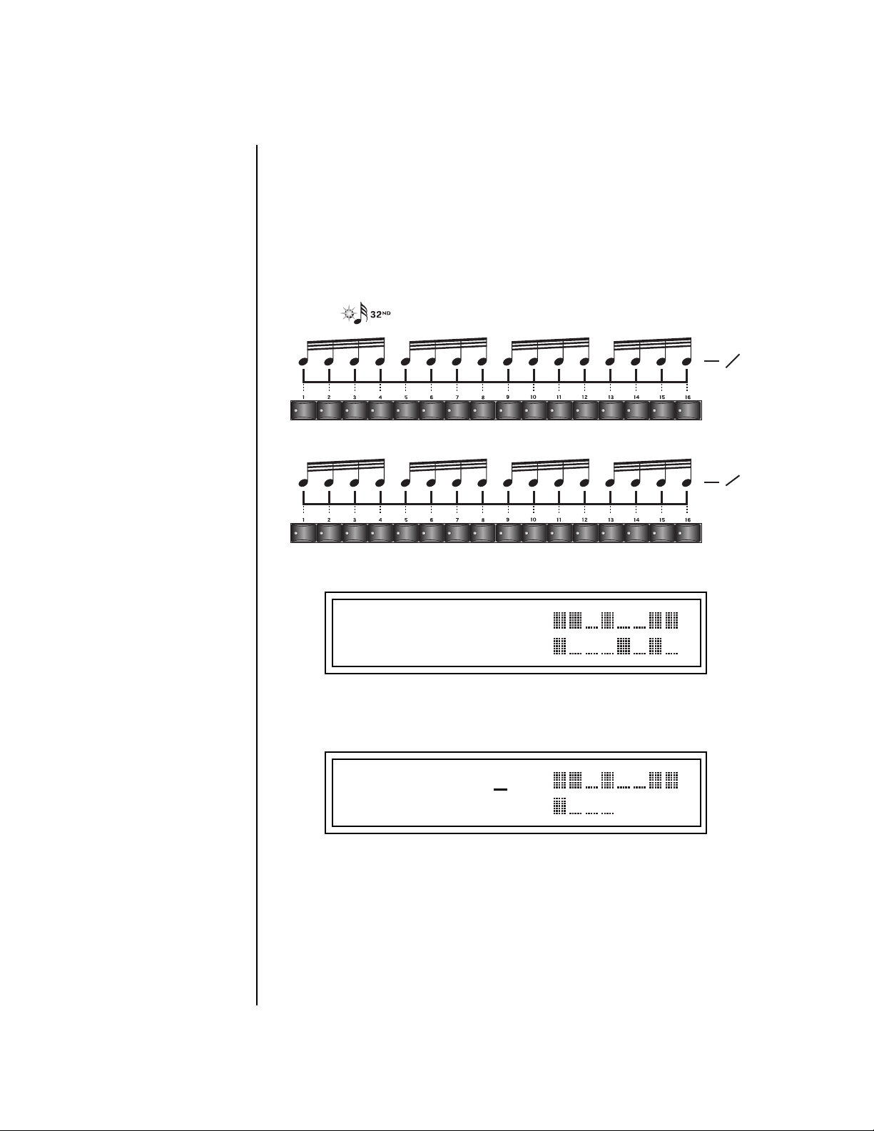
OO
OO
Press and hold Play, then
press Record while a pattern is
playing to jump right into Grid
Record mode.
Sequencer
Pattern Mode
The grid can be set up for 16th notes, 32nd notes, 8th note triplets or 16th
note triplets.
When using 32nd notes or recording patterns longer than one bar, the grid
displays as much of the pattern as it can then switches to the next section.
When playing one bar of 32nd notes, for example, the sixteen grid buttons
and LEDs show the first 16 notes, then switch to the second group of
sixteen notes.
1
32
1
32
The liquid crystal display shows the status of the16 grid locations.
T
01 GRID K: D5
B: 1. 1 03 V: 127
The time signature determines how the grid is laid out. The pattern below is
in 3/4 time and so only12 locations are needed.
T
01 GRID K: D5
B: 1. 1 03 V: 127
Grid mode can also be used in conjunction with either of the other record
modes. You can go into grid record mode and edit a pattern you created in
realtime record mode, or you could start with grid recording and record
over it in either realtime or step mode.
To examine a pattern in grid mode, place the cursor under the Key field and
turn the data entry control while the pattern is playing. When you find a
recorded note, you’ll see bars appear and the grid button LEDs will
illuminate.
64 E-MU Systems
Page 77

Sequencer
Pattern Mode
To Record a Pattern using Grid Recording:
1. Press the Pattern mode button. The screen shown below appears.
T
01 STOP Ln: 08 Bar: 01. 1
0
000
2. Select an empty sequence to begin recording using the data entry
control.
3. For now, set the pattern Length to 1 Bar. This will make Grid mode
easier to understand at first.
4. Press the Record button. The Realtime LED illuminates and the screen
shown below appears.
T
Start of IT
01 REC Ln: 01 Bar: 01. 1
Quan: 8 Met: on Cnt: 0
5. Press the Record button again. The Grid LED illuminates and the screen
shown below appears.
V:000
Current
Key
Velocity
8 note
positions
_ _ _ _ _ _ _ _
_ _ _ _ _ _ _ _
8 note
positions
Track
Number
T
01 GRID K: C1
B: 01. 1
Bar:Beat Note
6. Press the Preset View button and select a preset to use for track one. A
“prc” or “kit” preset might be a good choice. Press the Preset View
button again after you’ve made your selection to return to the Grid
recording screen.
7. Select a note using the rubber keypad. Press the transposition buttons
to find other sounds. Note that the Current Key field in the LCD
changes as you play the keypad.
8. Now turn on a few of the grid buttons. It doesn’t matter which for now.
9. Press Play. You’ll be hearing some sort of rhythm.
10. Go ahead and change the grid buttons. Play around until you get
something you like.
XL-7 Owners Manual 65
Page 78

Sequencer
Pattern Mode
The LCD will now probably look something like the next screen. The
vertical bars correspond to the grid buttons you’ve selected.
T
01 GRID K: D5
OO
OO
You could also assign
each new part to another Track
… or not. It’s up to you.
OO
OO
If you accidentally press
the Stop button by mistake,
simply press the Record button
twice to return to Grid mode.
OO
OO
You can also use the
data entry control to select
notes.
B: 01. 1
Another Rhythm?
11. Without even stopping, play another note. Keep hunting until you find
one you like. The last played key will be the selected sound.
12. With the new sound selected, turn on some grid buttons. (Note that
they all went off when you changed sounds.)
Change of Velocity
13. To pause the sequencer without exiting Grid mode, press the Play
button. Press the Play button again to continue.
14. Press one of the Grid buttons. The flashing cursor is now positioned
underneath that bar in the display.
T
01 GRID
V: 127
K: D5
B: 01. 1 V: 127
15. Now turn the data entry control. The height of the selected bar
changes, as does the velocity readout. This is one way to change the
velocities of grid notes. (You can also simply play the velocity on the
keypads.)
16. Turn some of the grid buttons on and off. Note that they now have the
same velocity as the last note you modified. Since velocity is often
coupled to volume in the preset, changing the velocities of notes can
have a dramatic effect on the sequence.
17. Now press the Home/Enter button. The cursor is now underneath the
Key field. pause the sequencer by pressing the Play button.
18. Re-key the note. If you didn’t hit the right note the bars will disappear.
When you find a recorded note the bars will reappear.
19. Re-key the note playing hard and soft on the keypads. Note that when
you select grid buttons, the last played velocity is used.
66 E-MU Systems
Double Time
20. With the sequencer running, select one of the Grid positions by
pressing its button.
21. Press the Repeat button located below the controller knobs. A number
now appears at the grid location which indicates the number of times
that the grid resolution has been increased for that location. For
example, if the number is 2, the note will play twice in that time slot.
Page 79

Sequencer
Pattern Mode
• Pressing the Erase button while the cursor is on one of the grid loca-
tions, removes the note from that location.
T
01 GRID K: D5
2
B: 1. 1 01 V: 127
22. Repeatedly pressing the repeat button increments the number. The
display goes up to nine times, but it will go even faster if you keep
pressing the repeat button. Special effects anyone?
23. The Erase button, located right next to the Repeat button, turns off the
grid locations (as does the grid button itself).
XL-7 Owners Manual 67
Page 80

Sequencer
Pattern Mode
Step Time Recording In this mode, you can insert events one at a time and place them exactly
where you want. In Step mode, key events, knobs or external MIDI events
are recorded into the current pattern step. The resolution of the step is
selected and indicated in the “Res” field on the LCD. In Step Record mode,
the Resolution (Res) setting determines the rhythmic value of each step. For
example, with Resolution set to 1/8 notes, you will step through the pattern
an eighth note at a time. Step recording records the actual “played” velocity
of note-on events.
Another cool feature is that each quantized step is from the current time
setting. This allows you to easily create complex offbeats using the quantize
feature.The way it works is simple. If you offset the current time using the
data entry control, the next step will be quantized from that point!
As an example, let’s say you started at Bar:01.01.0000 with Resolution set to
8. The next step would be Bar:01.01.0192, the next at Bar:01.02.0000 and
so on. If the initial time setting was instead, Bar:01.01.0050, the next step
would be, Bar:01.01.0242 (192 + 50).
When Auto mode is enabled (Y), the step is automatically incremented
when a note is entered. The step is not recorded and incremented until the
last “key up” of a chord. This allows you to make changes to the step as
long as one key is still held.
The Gate field allows you to set the note-on duration for note-on events. A
setting of 50% with eighth note resolution would keep the note held for
half that period (or a 16th note). Settings of greater than 100% hold the
note over into the next note.
Note Value/Number of Ticks
Resolution Ticks Resolution Ticks
Whole notes 1536 Eighth note triplets 128
Half notes 768 Sixteenth notes 96
Quarter notes 384 Sixteenth notes triplets 64
Quarter note triplets 256 32nd note 48
Eighth notes 192 32nd note triplets 32
To Record a new Pattern in Step Time:
1. Press the Pattern mode button. The screen shown below appears.
T
01 STOP Ln: 02 Bar: 01. 1
0
000
Start of IT
68 E-MU Systems
2. Select an empty sequence to begin recording using the data entry
control.
Page 81

Sequencer
Pattern Mode
3. Set the Pattern Length. Choose a one or two bar length to start.
4. Press the Record button three times to select Step Record mode. The
screen shown below appears.
Track
Bar
Number
T
01 STEP Bar: 01. 01. 0000
Beat Tick
Res: 8 Gate: 85% Auto:Y
Step
Resolution
5. Select a Track number. The default value is Track one.
6. Turn Auto Increment On. This feature automatically increments the
Gate On
Percentage
Auto Increment
On/Off
step (by the selected step resolution) each time you press the Play
button.
7. Press the Preset View button. The preset screen shown below appears.
C01A V127 P00 A:P User
3
050
8. Select a Preset for your first track.
9. Press the Preset View button again after you’ve selected a preset. The
LED will go out and you’ll be returned to the Pattern screen.
Get ready to record!
10. Set the Step Resolution to eighth notes for now (8).
11. Play a note (or notes) on the keypad. The step records and increments
when you release the keys. Note the setting of the bar.beat.tick display
as the steps increment.
12. Keep adding notes to steps. You can also record knob settings. Simply
turn the knobs in any of the controller knob modes and these moves
will be recorded.
13. Press Stop when you’ve finished recording.
14. Press Stop again to rewind to the beginning of the pattern.
15. Change the Resolution and record another pass.
kit:80’s Tones
To Erase the Pattern:
16. There are several ways to erase entire pattern. Probably he easiest way is
to simply Save an empty sequence over the pattern you want to erase.
• You could also “Erase All Events” from the Pattern Edit menu.
XL-7 Owners Manual 69
Page 82

Sequencer
Pattern Edit Menu
Pattern Edit
Menu
Track Enable/Mute Buttons
The Pattern Edit menu contains housekeeping, pattern editing filters and
other tools.
The Pattern Edit button is DISABLED unless you are in Pattern Mode!
IMPORTANT: In Pattern Edit mode, Track Enable/Mute buttons are used
to select which tracks will be affected by the editing operation.
Any enabled tracks will be edited and any disabled tracks will be unaffected
by the editing operation—Quantize, Thin Events, Erase Events, Velocity
Scale/Shift, Extend or Transpose.
Name Pattern Patterns can be named with up to 16 characters. Position the cursor under
the character location and use the data entry control to change the
character.
PATTERN NAME
0061 Metallic 6
Pattern Length Patterns can be anywhere from one to thirty two measures in length. A
pattern loops when it reaches the end whether in record or playback
modes.
A pattern’s length can also be changed at any time, before or after
recording. If you increase the length of a pattern after recording, it will play
silently for the extra time unless new data is recorded there. If you shorten
a pattern’s length after recording, it will play up to it’s new length then
loop. Changing the length of a pattern does not change any data until you
save it. If you save a shortened pattern, the unplayed data will be erased.
To Set the Pattern Length from the Pattern Edit menu:
1. Select Pattern Edit mode from Pattern mode.
2. Locate the Pattern Length screen using the data entry control.
PATTERN LENGTH
Length: 32 bars
3. Move the cursor to the lower line of the display using either cursor key,
then set the length of the pattern using the data entry control.
70 E-MU Systems
Page 83
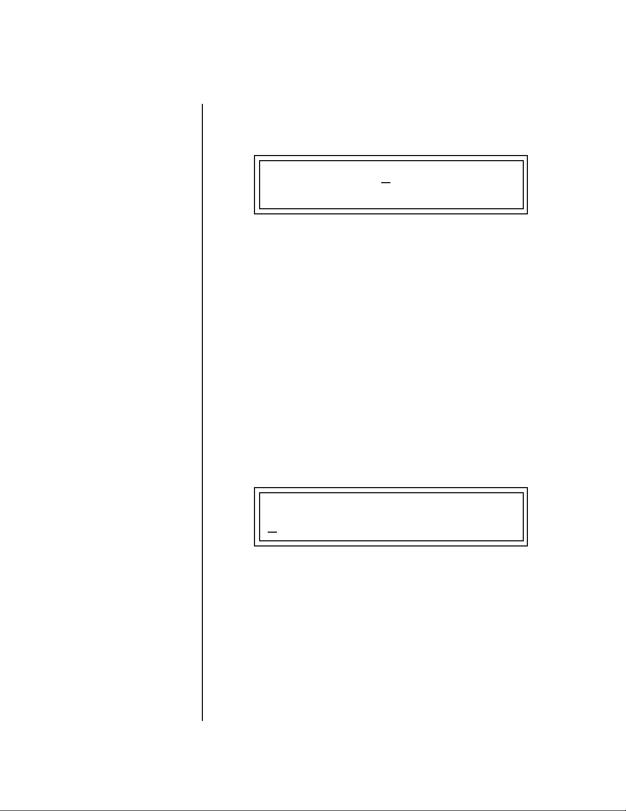
Pattern Edit Menu
To Set the Pattern Length from the Main Pattern Screen:
1. Select the pattern in Pattern mode.
2. Move the cursor to the Length (Ln) field using the cursor keys.
T
01 STOP Ln: 02 Bar: 01 . 1
0
000
3. Set the Length of the pattern using the data entry control.
Start of IT
Sequencer
Setting Meter (Time Signature)
XL-7 allows you to set almost any conceivable time signature. The
numerator (indicating number of beats in a measure) can be set from 1 to
99. The denominator (indicating the rhythmic value of each beat) can be
set to 1, 2, 4, 8, 16, 32, or 64. The time signature can be changed at any
time before or after recording.
The meter setting affects the bar:beat display, the pattern length,
metronome accent, and the grid recording display.
For background information about Time Signatures, see page 316.
To Set the Time Signature:
1. Select the pattern in which you want to record.
2. Press the Pattern Edit button. The Pattern Edit menu screen displays
the menu page most recently selected since powering up XL-7.
3. Scroll to the Meter screen using the data entry control. The meter
setting will probably show the 04/4 default time signature.
METER METRONOME VALUE
04 / 4 off 1/8
4. Press the right cursor button once to move the cursor underneath the
numerator field.
5. Set the time signature numerator value using the data entry control.
6. Press the right cursor button again to move the cursor underneath the
denominator field.
7. Set the time signature denominator value using the data entry
control.
8. Press the Pattern Edit button again to exit pattern edit mode.
XL-7 Owners Manual 71
Page 84

Sequencer
Pattern Edit Menu
Metronome The metronome is a timing aid when recording or playing back patterns
and songs and can be set to a wide variety of different beats. The
metronome produces an accented click on the first beat of each measure
and a softer click on other beats. The following metronome beat options are
available:
OO
OO
The higher metronome
speeds are useful when recording
a fast part since you may slow
the tempo way down and still
hear where you are in the
pattern.
Symbol Symbol
1/1 whole notes 1/2d dotted half notes
1/2 half notes 1/4d dotted quarter notes
1/4 quarter notes 1/8d dotted eighth notes
1/8 eighth notes 1/4t quarter note triplets
1/16 sixteenth notes 1/8t eighth note triplets
1/32 thirty-second notes 1/16t sixteenth note triplets
denom uses the denominator
value of the meter setting
OO
OO
Play the pattern to listen
to the Metronome while you set
the Value.
The metronome setting is NOT saved with the pattern.
To Set the Metronome:
1. Press the Pattern Edit button. The Pattern Edit menu screen displays
the menu page most recently selected since powering up XL-7.
2. Scroll to the Metronome screen using the data entry control.
METER METRONOME VALUE
04 / 4 off 1/8
3. Move the cursor underneath the Metronome field and turn the
metronome to On, Off or Rec using the data entry control.
• Off - the metronome doesn’t play.
• On - the metronome plays during recording and playback.
• Rec - the metronome only plays while recording.
4. Move the cursor underneath the Value field and set the metronome
beat value using the data entry control.
72 E-MU Systems
Page 85

Sequencer
Pattern Edit Menu
Quantize The timing can also be changed after a pattern has been recorded. Quantize
moves all the note start times in the track to fall on (or closer to) the
specified time values.
To Quantize a Pattern:
1. Select the pattern.
2. Select the Track(s) you wish to quantize using the Track Enable/Mute
buttons.
3. Press the Pattern Edit button.
4. Scroll to the Quantize screen shown below using the data entry
control.
QUANTIZE Resolution: 16
Amount: 75% Swing: 50%
5. Set up the Quantize parameters as desired. The Home/Enter LED will
be flashing once the cursor is moved to one of the editable fields.
6. Press Enter to Quantize or add Swing. Press any other button to Cancel
the operation.
Quantize Parameters
Resolution- Sets the desired note value to which note-on events will be
corrected. With sixteenth notes selected, Quantize will move
played notes toward, or exactly onto, sixteenth note time slots.
Amount - Controls how much quantization is applied. With a setting of
100%, events are moved all the way to the specified note value.
With a setting of 50%, events are moved 50% closer to the
specified note value.
Before
After
Quantization
With an amount of 50%, notes are moved 50% closer to the
specified Quantization value.
Swing - Swing adds a rhythmic feel by shifting the time allocated to
every other grid point in a pattern. In the default case where
swing is set to 50% (No Swing), the first eighth note takes up
50% of the quarter note and the second eighth note takes up
the remaining 50% of the time.
Resolution: 8
Amount: 50%
XL-7 Owners Manual 73
Page 86

Sequencer
Pattern Edit Menu
50% Swing
Eighth notes play at regular intervals
50%
100%0%
If swing were set to 67%, the first eighth note falls on the beat, but the
second eighth note is delayed by 67%.
67% Swing
Every other eighth note plays late
0%
Values below 50% give a kind of “reverse swing” where every other eighth
note comes in early. Odd, but maybe just the thing for your style of music.
67%
30% Swing
Every other eighth note plays early
30%
More about Swing
Swing can help add a more human “feel” to a series of repeating patterns.
For example, if you repeat the same pattern four times, try setting a swing
factor of 54% for, say, the third pattern. This results in a series of patterns
which are more psycho-acoustically interesting than merely repeating the
same pattern over and over.
67% is considered the “classic” jazz swing factor, where the first eighth note
is 2/3 of a quarter note, and the second eighth note is 1/3 of a quarter note
(i.e. the second eighth note behaves more like an eighth note triplet). If this
sounds too “perfect”, try a swing factor of 64% instead. The results will be
similar, but the “feel” will be slightly different.
74 E-MU Systems
Page 87

Sequencer
Pattern Edit Menu
Scale/Shift Duration This filter allows you to either scale (multiply by a value) or shift (add a
value to) the note durations in the selected tracks. The Scale function is
performed before the Shift value is added.
Scale - Multiplies all note durations by a percentage from 0% to 125%.
Scaling by 100% would leave all note durations untouched.
Scaling by 50% would cut all note durations in half.
Shift - Adds or subtracts a specific note duration in quarter notes and
ticks to note-on events in the selected tracks.
To Scale or Shift Note Duration:
1. Select the pattern you wish to edit.
2. Select the Track(s) you wish to Scale or Shift using the Track Enable/
Mute buttons.
3. Press the Pattern Edit button.
4. Scroll to the Scale/Shift Note Duration screen shown below using the
data entry control.
OO
OO
Tip: To set all notes to a
particular value, set Scale to 0%,
(this zeros the value) then set
Shift to the desired duration.
SCALE/SHIFT NOTE DURATION
Scale: 87% Shift: +00.000
Quarter Notes Ticks
5. Select the amount of note duration scaling or shift (offset). The
Home/Enter LED will be flashing once the cursor is moved to the lower
line of the display.
6. Press Enter. The screen shown below appears to remind you to select
the tracks you want to filter. Select a key range for filtering. The default
setting is all keys.
SELECT TRACKS
Key Range: C-2 to:G8
Low Key High Key
7. Press Enter to scale/shift the note durations. Press any other menu
button to Cancel the operation.
XL-7 Owners Manual 75
Page 88

Sequencer
Pattern Edit Menu
Thin Events Event thinning is usually performed to reduce the amount of extraneous
controller data and thus reduce the memory size of patterns. This filter
reduces the number of events in a musical fashion. Events may be reduced
by a specified amount from 1 to 128. The setting represents the smallest
change that will be kept. For example, if the setting were set to 3 and you
were thinning a controller sweep that went 1-2-3-4-5-6-7, you would be left
with:1-4-7. The filter also keeps any change in direction values.
1
2
3
4
5
6
7
The setting
represents the smallest
change that will be kept.
1
(All the “|” get kept.)
3
3
4
3
7
Direction Changes are always kept.
__
__
If too much data is
recorded into a pattern, the
sequencer may slow or clog. Use
the “Thin Events” function to
reduce the amount of
extraneous data in the pattern.
The following types of events can be thinned:
• Tempo
• Poly Aftertouch
• Channel Aftertouch
• Pitch Wheel (Touchstrip)
• Any Continuous Controller (1-95)
To Thin Events in a Pattern:
1. Select the pattern you wish to edit.
2. Select the Track(s) you wish to thin using the Track Enable buttons.
3. Press the Pattern Edit button.
4. Scroll to the Thin Events screen shown below using the data entry
control.
THIN EVENTS
chan aftertouch Amt: 40
5. Select the type of event you want thinned, then set the amount of
thinning. The Home/Enter LED will be flashing once the cursor is
moved to one of the editable fields.
76 E-MU Systems
Page 89

Pattern Edit Menu
6. Press Enter. The screen shown below appears to remind you to select
the tracks you want to thin. Select a key range for thinning. The default
setting is all keys.
SELECT TRACKS
Key Range: C-2 to:G8
Low Key High Key
7. Press Enter to thin events. Press any other menu button to Cancel the
operation.
Erase Events Specific types of events can be completely erased from a pattern.
The following types of events can be erased:
• All Track Events
• Notes
• All Controllers
• Program Changes
• SysEx Data
• Meter
• Tempo
• Poly Aftertouch
• Channel Aftertouch
• Pitch Wheel (Touchstrip)
• Any Continuous Controller (1-119)
Sequencer
To Erase Events from a Pattern:
1. Select the pattern you wish to edit.
2. Select the Track(s) you wish to erase using the Track Enable/Mute
buttons.
3. Press the Pattern Edit button.
4. Scroll to the Erase Events screen shown below using the data entry
control.
ERASE EVENTS
program change
5. Select the type of events you want erased. The Home/Enter LED will be
flashing once the cursor is moved to the lower line of the display.
XL-7 Owners Manual 77
Page 90

Sequencer
Pattern Edit Menu
6. Press Enter. The screen shown below appears to remind you to select
the tracks you want to erase. Select a key range. The default setting is all
keys.
SELECT TRACKS
Key Range: C-2 to:G8
7. Press Enter to erase the events. Press any other menu button to Cancel
the operation.
Transpose All notes in a pattern can be transposed up or down from -127 to +127
semitones. For example with a setting of +7, all notes in the pattern would
be transposed up a perfect fifth.
Warning: If you transpose notes past the hard limits of 0 and 127, those
notes will be erased from the pattern.
To Transpose a Pattern:
1. Select the pattern you wish to edit.
2. Select the Track(s) you wish to Transpose using the Track Enable/Mute
buttons.
3. Press the Pattern Edit button.
4. Scroll to the Transpose screen shown below using the data entry
control.
TRANSPOSE
+7 semitones
5. Select the amount of transposition you want. The Home/Enter LED
will be flashing once the cursor is moved to the lower line of the
display.
6. Press Enter. The screen shown below appears to remind you to select
the tracks you want to transpose. Select a key range. The default setting
is all keys.
SELECT TRACKS
78 E-MU Systems
Key Range: C-2 to:G8
7. Press Enter to transpose the selected tracks. Press any other button to
Cancel the operation.
Page 91

Sequencer
Pattern Edit Menu
Scale/Shift Velocity This filter allows you to either scale (multiply by a value) or shift (add a
value to) the velocity values of notes in a pattern. The Scale function is
performed before the Shift value is added.
Scale - Multiplies all note-on velocities by a percentage from 0% to
125%. Scaling by 100% would leave all velocity values
untouched. Scaling by 50% would cut all velocity values in half.
Shift - Adds or subtracts a specific velocity value (-127 to +127) to
every note-on event in the pattern.
To Scale or Shift Velocity:
1. Select the pattern you wish to edit.
2. Select the Track(s) you wish to Scale or Shift using the Track Enable/
Mute buttons.
3. Press the Pattern Edit button.
4. Scroll to the Scale/Shift Velocity screen shown below using the data
entry control.
OO
OO
Tip: To set all notes to a
particular velocity value, set
Scale to 0%, then set Shift to the
desired velocity.
SCALE/SHIFT VELOCITY
Scale: 87% Shift: +0
5. Select the amount of velocity scaling or shift. The Home/Enter LED
will be flashing once the cursor is moved to the lower line of the
display.
6. Press Enter. The screen shown below appears to remind you to select
the tracks you want to velocity scale or shift. Select a key range. The
default setting is all keys.
SELECT TRACKS
Key Range: C-2 to:G8
7. Press Enter to change velocity in the selected tracks. Press any other
button to Cancel the operation.
XL-7 Owners Manual 79
Page 92

Sequencer
Pattern Edit Menu
Extend Sequence Data To
This feature lets you change the length of any selected tracks after recording
a pattern. If you are lengthening a pattern, the pattern is looped to fill in
the empty space. If you set the length shorter than the existing pattern, the
pattern will be truncated.
You can set the pattern length before you extend so that only those
bars will be copied. The copied data will be merged with the data in the
subsequent bars of the pattern.
To Extend the 1st Bar over 4 Bars
1. Set Pattern
Length to 1-bar
Bar 1 Bar 2 Bar 3 Bar 4
2. Extend Sequence
Data to 4-bars
Bar 1 Bar 2 Bar 3 Bar 4
To Extend the Length of Selected Tracks:
1. Select the pattern you wish to extend.
2. Select the Track(s) that you want to extend using the Track Enable/
Mute buttons.
3. Press the Pattern Edit button from pattern mode.
4. Scroll to the Pattern Length screen and set the length to the measures
you wish to extend. For example, if you want to copy the first measure,
set the length to 1.
5. Scroll to Extend Sequence Data using the data entry control.
80 E-MU Systems
EXTEND SEQUENCE DATA TO
bar: 8
6. Move the cursor to the lower line of the display and select the new
pattern length.
7. Press Enter. The following screen appears.
--- PERFORM OPERATION? ---
Enter = Yes Other = Cancel
8. Press Enter again to extend the pattern or any other menu button to
cancel the operation.
Page 93

Sequencer
Pattern Edit Menu
Erase Track An entire track or a section of a track can be erased in a single operation.
This feature makes it easy to erase a flubbed take or erase a section of track
before pasting new data.
Erase Pattern or Song Track
Start
Length = 3Bars
Bar
Before
Bar -12345678
After
Bar -12345678
To Erase a Track:
1. Press the Pattern Edit or Song Edit button.
2. Scroll to the Erase Track screen shown below using the data entry
control.
ERASE TRACK
Track: 1 Bar:01 Len:32
Track to be
Erased
3. Select the track you want to erase. The Home/Enter LED will be
Start
Location
Length in
bars
flashing once the cursor is moved to the lower line of the display.
4. Select the first Bar you want to erase. The bar range for patterns is 01-
32; the bar range for songs is 001-999.
5. Select the Length of the track you want erased.
6. Press Enter to erase the selected section of the Track.
7. Press any other menu button or exit the edit menu to Cancel the
operation.
XL-7 Owners Manual 81
Page 94
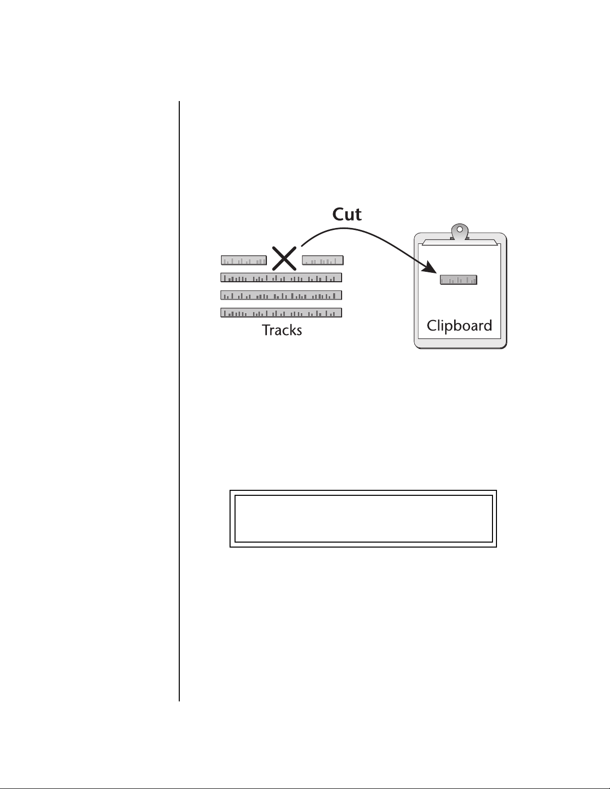
Sequencer
Pattern Edit Menu
Cut Track to Clipboard
OO
OO
Cut track can be used as
a way to erase a track.
An individual track or a section of a track can be cut or copied and held on
a digital “clipboard” so that it can be pasted into another track or pattern.
This function cuts or removes a track (or section of a track) from the pattern
and places it on the clipboard, where it will be held until it is replaced with
another cut or copy operation, or the power to XL-7 is turned off.
Cutting a section from a track will leave a blank space in the track.
The cut section is placed on the clipboard leaving a blank space in the
track where the data was cut out.
OO
OO
Tracks can be freely cut,
copied or pasted between songs
and patterns.
To Cut a Track:
1. Select the pattern you wish to edit.
2. Press the Pattern Edit button.
3. Scroll to the Cut Track to Clipboard screen shown below using the
data entry control.
CUT TRACK TO CLIPBOARD
Track: 1 Bar:04 Len:07
4. Select the track to be cut. The Home/Enter LED will be flashing once
the cursor is moved to the lower line of the display.
5. Select the Start Bar and the Length (in bars) to be cut.
6. Press Enter to cut the track. Press any other menu button to Cancel the
operation.
82 E-MU Systems
Page 95

Sequencer
Pattern Edit Menu
Copy Track to Clipboard
An individual track or a section of a track can be copied and held on a
digital “clipboard” so that it can be pasted into another track or pattern.
This function makes a digital copy of the selected track and places it on the
clipboard, where it will be held until it is replaced with another cut or copy
operation, or the power to is turned off.
To Copy a Track:
1. Select the pattern you wish to edit.
2. Press the Pattern Edit button.
3. Scroll to the Copy Track to Clipboard screen shown below using the
data entry control.
COPY TRACK TO CLIPBOARD
Track: 1 Bar:06 Len:07
4. Select the track to be copied. The Home/Enter LED will be flashing
once the cursor is moved to the lower line of the display.
5. Select the Start Bar and the Length (in bars) to be copied.
6. Press Enter to copy the track. Press any other menu button to Cancel
the operation.
XL-7 Owners Manual 83
Page 96

Sequencer
Pattern Edit Menu
Paste Clipboard to Track
Once a track (or a section of a track) has been cut or copied to the
“clipboard”, it can be pasted into another track or pattern from 1 to 99
times. The Paste operation Merges the clipboard data with the data on the
destination track. It adds the new information to the existing data with the
start of the data in the clipboard placed at the selected bar position.
Because of the data merging feature, the Paste operation can be used to
“bounce down” multiple tracks to a single multichannel track. See below.
Specified
Bar
Tracks
Paste
Clipboard
Paste x3
OO
OO
Tracks can be freely cut,
copied or pasted between songs
and patterns.
Specified
Bar
12
Total Extension = 6 bars
To Paste the Clipboard into a Track:
1. Press the Pattern Edit button.
2. Cut or Copy data to the clipboard. See pages 82 and 83.
3. Scroll to the Paste Clipboard to Track screen shown below using the
data entry control.
3
2-bars
Clipboard
PASTE CLIPBOARD TO TRACK
Track: 1 At Bar:06 X:3
Destination
Track
Start
Location
Number
of Pastes
84 E-MU Systems
Page 97

You will not hear the
results of the Paste operation
until the sequence cycles around.
(Hint: Press RTZ)
Sequencer
Pattern Edit Menu
4. Select the track where you want the clipboard data to be pasted. The
Home/Enter LED will be flashing once the cursor is moved to the lower
line of the display.
5. Select the bar where the clipboard contents will be pasted.
6. Select the number of times you want the clipboard data pasted.
7. Press Enter to paste the data. Press any other menu button to Cancel
the operation.
To Bounce Tracks:
1. Copy the first track you wish to bounce.
2. Paste the track to the desired destination track.
3. Repeat steps 1 & 2 for the other tracks you wish to bounce down.
4. Press the Pattern Edit button and scroll to the Channel Assign screen.
5. Set the Track containing all your bounced tracks to MultiA.
(or MultiB if the original tracks were recorded using the “B” channels.)
XL-7 Owners Manual 85
Page 98

Sequencer
Pattern Edit Menu
Channel Assign This important screen assigns each track to a Main channel (01A-16B). This
“rechannelizes” the data on the track to the channel you choose here. The
default mode of operation for XL-7 is to have tracks assigned to the samenumbered MIDI channel. This convention makes it easy to keep everything
organized and it works well for most recording.
Because tracks can be recorded with multiple MIDI channels, “Multi A” and
“Multi B” options are provided in the channel selection field. The Multi
options route data to either the A or B channels (internal or external). For
example, you could route a multichannel track to only use the B channels.
Each track can also be routed to: internal MIDI channels, the external MIDI
ports, both, or none. Channels 1A-16A and Multi A are routed to MIDI port
A and channels 1B-16B and Multi B are routed to MIDI port B, if “ext” or
“both” is selected as a destination for that track.
OO
OO
You might want to
designate a certain track to
handle external program
changes. Set this track to “Ext”
and choose “MultiA” or
“MultiB”.
Important Note: Program change messages are NOT transmitted externally if the destination is set to Both. To transmit program changes to
external MIDI devices, set the destination to External (EXT).
Track Channel Destination
Track
1
Track
2
Track
3
Track
16
Multiple
Channels
Chan
1A
Chan
2A
Multi
B
Chan
3B
both
Internal
Internal
Internal
Internal
86 E-MU Systems
none
Page 99

Sequencer
Pattern Edit Menu
To Assign Tracks to MIDI Channels:
1. Select the pattern you wish to edit.
2. Press the Pattern Edit button.
3. Scroll to the Select Track Changes screen shown below using the data
entry control.
T
01 CHANNEL ASSIGN
Channel: 01A: Dest:both
4. Select the desired track(s).
5. Select the desired channel for the track.
6. Select the desired destination for the track.
7. Press the Pattern Edit button again to exit the module.
Multichannel Track Recording
OO
OO
The Channel Assignment
screen is a MIDI rechannelizer.
The Multi A or B assignments
allow multiple MIDI channels on
a track.
Each of XL-7‘s 16 tracks can contain multichannel MIDI data. Because
tracks can be routed internally or externally on either of the two MIDI
ports, the XL-7 sequencer can actually control up to 64 separate MIDI
channels (16 internal-A, 16 internal-B, 16 MIDI port-A, 16 MIDI port-B).
Once a track is enabled for multichannel recording you can record into it
using the rubber keypads or external MIDI.
To Setup a Track for Multichannel Recording
1. Select the pattern you wish to record.
Playback Setup (steps 2-7 set up the track for multi-channel play back)
2. Press the Pattern Edit button.
3. Scroll to the Select Track Changes screen shown below using the data
entry control.
T
01 CHANNEL ASSIGN
Channel: 01A: Dest:both
4. Select the desired track.
5. Set the track to MultiA or MultiB.
6. Select the desired destination for the track (internal, external or both).
7. Press the Pattern Edit button again to exit the module.
XL-7 Owners Manual 87
Page 100

Sequencer
Pattern Edit Menu
Continue on to Record a Multichannel Track using the Rubber Keypads…
8. Press the Controllers button and make sure “Keyboard/Knob Channel”
is set to “Basic”. This feature automatically changes the channel of the
keypad to whatever channel is shown in the preset view display.
9. Make sure the multichannel track you set up (step 4 above) is selected.
10. Set the Pattern Length.
Ready to Record
11. Press the Preset View button.
12. Select a preset for channel 01A.
13. Press Record, then Play. Start playing!
Record Channel 2
14. Select channel 02A.
15. Select a preset for channel 02A.
16. Press Record, then Play. Start playing!
17. Continue to record channels.
Aux Channel Assign Each track can also be assigned to a separate Aux channel. This assignment
works exactly like the main channel assignment (page 86). In certain situations it may be useful to transmit using two MIDI channels or both MIDI
ports.
The Aux Channel assignments are NOT saved with the pattern or multisetup and reverts to its default state upon power-up.
88 E-MU Systems
 Loading...