

Page 1

Owners Manual
© 2002 E-MU Systems
All Rights Reserved
FI12322 Rev. C
E-MU World Headquarters Europe, Africa, Middle East
E-MU Systems E-MU Systems
1600 Green Hills Road Suite 6, Adam Ferguson House
Scotts Valley, CA USA Eskmills Industrial Park
95066 Musselburgh, East Lothian
Telephone: 831-438-1921 Scotland, EH21 7PQ
Fax: 831-438-8612 Tel: +44 (0) 131-653-6556
Internet: www.emu.com Fax: +44 (0) 131-665-0473
Important Notice:
In order to obtain warranty service on your XK-6 unit, the serial number sticker
must be intact and you must have a sales receipt or other proof of purchase. If
there is no serial number sticker on the XK-6, please contact E-MU Systems at
once.
This product is covered under one or more of the following U.S. patents:
4,404,529; 4,506,579; 4,699,038; 4,987,600; 5,013,105; 5,072,645;
5,111,727; 5,144,676; 5,170,367; 5,248,845; 5,303,309; 5,317,104;
5,342,990; 5,430,244 and foreign patents and/or pending patents. All other
trademarks belong to their respective companies. Specifications and features are
subject to change without notice.
XK-6 Owners Manual
i
Page 2

Table of Contents
Introduction ............................................................................. 1
Product Description .......................................................................................1
Important Safety Instructions .................................................. 3
Safety Instructions - German ................................................... 6
Safety Instructions - French ..................................................... 8
Setup ...................................................................................... 13
Unpacking....................................................................................................13
Connection Instructions..............................................................................14
Basic Setup ..............................................................................................14
Performance Setup .................................................................................15
Studio Setup ............................................................................................16
Instant Gratification ............................................................... 19
Playing Demo Sequences ........................................................................19
Auditioning Presets .................................................................................20
Selecting and Quick Editing Presets .......................................................20
Exploring Beats Mode .............................................................................22
Exploring the Master Arpeggiator ...........................................................24
Multi-Channel Arpeggiator ....................................................................26
Time to Save? .......................................................................................28
Basic Operations .................................................................... 29
Power Switch ...........................................................................................29
Volume Control ......................................................................................29
Channel +/- Buttons ...............................................................................29
Data Entry Control .................................................................................29
Cursor Buttons ........................................................................................30
Pitch & Mod Wheels ...............................................................................30
ii
E-MU Systems
Page 3

Edit Section..................................................................................................30
Global Button .........................................................................................30
Controllers Button .................................................................................. 30
Arp/Beats Button ....................................................................................31
MIDI Button ...........................................................................................31
MIDI Panic Button .................................................................................. 31
Audition Button ...................................................................................... 31
Compare Button .....................................................................................31
Save/Copy Button ................................................................................... 31
Preset Edit Button ................................................................................... 32
Home/Enter Button ................................................................................32
Real-time Controller Knobs .........................................................................32
Knob Functions ......................................................................................33
Quick Edit mode .................................................................................33
Screen View Buttons ....................................................................................34
Main ........................................................................................................ 34
Multi ....................................................................................................... 34
Mix Screen .............................................................................................. 34
Demo Mode ............................................................................................35
Command Functions................................................................................... 36
Preset Selection ....................................................................................... 36
Trigger Mode ........................................................................................... 36
Preset Menu Jump Keys ..........................................................................36
Main Screen .................................................................................................37
MIDI Channel Selection ......................................................................... 37
Preset Selection ....................................................................................... 37
Channel Volume ....................................................................................38
Channel Pan ...........................................................................................39
Channel Arpeggiator .............................................................................. 39
Sound Navigator ..........................................................................................40
Preset Category .......................................................................................40
Instrument Category ..............................................................................40
Multisetups ..................................................................................................41
Restoring Multisetups ............................................................................. 41
Multisetup Name ....................................................................................42
Saving Multisetups .................................................................................42
Arp/Beats Menu ......................................................................43
Beats.............................................................................................................44
Beats Mode .............................................................................................. 46
Status ................................................................................................... 46
Beats Channel ......................................................................................46
Trigger Channel ..................................................................................46
Beats Controllers ..................................................................................... 49
Beat Velocity Group 1-4....................................................................... 49
Beat Xpose Group 1-4 ......................................................................... 49
Beat Busy .............................................................................................49
Beat Variation....................................................................................... 50
XK-6 Owners Manual
iii
Page 4

Beats Keys Layout ...................................................................................51
1-Bar Trigger Option ...........................................................................51
Beats Keys Offset .....................................................................................52
Beats Part Velocity ..................................................................................52
Beats Part Transpose ...............................................................................53
Beats Part Group .....................................................................................54
Master Riff ...............................................................................................54
Riff Tempo ..............................................................................................55
Riff Controllers .......................................................................................55
MIDI Song Start ......................................................................................56
Arp/Riff MIDI Out ...................................................................................56
Arpeggiators .................................................................................................57
Arp Controllers .......................................................................................58
Arpeggiator Resolution.........................................................................58
Arpeggiator Extension .........................................................................58
Arpeggiator Velocity.............................................................................58
Arpeggiator Gate ..................................................................................58
Arpeggiator Interval ............................................................................58
Master Arpeggiator Parameters ....................................................................58
Status .......................................................................................................59
Mode .......................................................................................................59
Note Value ..............................................................................................60
Arpeggiator Pattern Speed ......................................................................60
Pattern .....................................................................................................60
Velocity ...................................................................................................61
Gate Time ................................................................................................61
Extension Count .....................................................................................62
Extension Interval ...................................................................................62
Sync .........................................................................................................63
Pre-Delay .................................................................................................63
Duration ..................................................................................................64
Post-Delay ...............................................................................................64
Recycle ....................................................................................................65
Keyboard Thru ........................................................................................65
Latch .......................................................................................................65
Send MIDI System Exclusive Data ...............................................................66
Editing a User Arpeggiator Pattern .........................................................67
Pattern Step Number ...............................................................................67
Key ..........................................................................................................67
Key Offset ............................................................................................68
Tie ........................................................................................................68
Rest ......................................................................................................68
Skip ......................................................................................................68
End .......................................................................................................68
Velocity ...................................................................................................69
Duration ..................................................................................................69
Repeat ......................................................................................................69
User Pattern Name ..................................................................................70
Multichannel Arpeggiating..........................................................................70
iv
E-MU Systems
Page 5

Controllers Menu ....................................................................71
Realtime Control Functions ........................................................................72
Keyboard Channel .................................................................................. 72
Keyboard Transpose ................................................................................ 72
Local Control On/Off .............................................................................72
Keyboard Velocity Curve ........................................................................ 73
Channel Aftertouch On/Off ................................................................... 74
Footswitch Function ............................................................................... 74
Foot Pedal Function ................................................................................ 75
Trigger Buttons Function ........................................................................ 75
Trigger Buttons ....................................................................................... 76
Trigger Button Select ........................................................................... 76
Latch on/off ........................................................................................76
MIDI Key ............................................................................................. 76
MIDI Channel .....................................................................................76
Velocity ............................................................................................... 76
Preset Select Buttons ............................................................................... 77
Trigger Button Select ........................................................................... 77
Preset Location .................................................................................... 77
Preset Number ..................................................................................... 77
Preset Name ......................................................................................... 77
Category .............................................................................................. 77
Preset Select Send Buttons ...................................................................... 78
Trigger Button Select ........................................................................... 78
Bank MSB ............................................................................................78
Program Change Number ...................................................................78
Bank LSB .............................................................................................. 78
Knob Preset Quick-Edit ........................................................................... 79
Real-time Controller Assignment ........................................................... 79
MIDI Footswitch Assign .........................................................................80
Calibrate Controllers .............................................................................. 80
Tempo Controller ................................................................................... 81
Base Tempo ............................................................................................. 82
Global Menu ...........................................................................83
Defining Global Parameters......................................................................... 84
Master Transpose/Tune ..........................................................................84
Master Bend Range .................................................................................84
Master Velocity Curve ............................................................................ 85
Mix Output ............................................................................................. 86
Master Effects............................................................................................... 88
Effects Mode ...........................................................................................88
Effects Multi Mode Control .................................................................... 88
Master FXA Algorithm ............................................................................ 89
A Effect Types ...................................................................................... 89
FXA Parameters: Decay/HF Damping FxB -> FxA ..................................90
FXA Send Amounts ................................................................................. 90
Master FXB Algorithm ............................................................................ 90
B Effect Types ......................................................................................91
XK-6 Owners Manual
v
Page 6

FXB Parameters: Feedback/LFO Rate Delay Time ...................................91
FXB Send Amounts .................................................................................91
Miscellaneous Parameters ............................................................................92
Edit All Layers Enable .............................................................................92
User Key Tuning .....................................................................................92
Screen Viewing Angle .............................................................................92
MIDI Menu ............................................................................. 93
Keyboard Outputs MIDI .........................................................................94
Knobs Output MIDI ................................................................................94
Transmit MIDI Clock ..............................................................................94
MIDI Enable ............................................................................................94
Receive Program Change ........................................................................95
MIDI Program Change -> Preset .............................................................95
MIDI SysEx ID .........................................................................................96
MIDI SysEx Packet Delay ........................................................................97
Send MIDI System Exclusive Data ..........................................................97
MIDI Mode ..............................................................................................98
Programming Basics .............................................................. 99
Modulation ................................................................................................100
Modulation Sources ...................................................................................101
Random Sources ....................................................................................102
Modulation PatchCords.............................................................................102
Envelope Generators..................................................................................103
Tempo-based Envelopes ....................................................................104
Envelope Repeat ................................................................................104
Low Frequency Oscillators (LFOs) .............................................................105
Clock Modulation ......................................................................................106
Modulation Destinations...........................................................................108
Modulation Processors...............................................................................109
Preset Modulation Processors ....................................................................111
Using the Modulation Processors .........................................................113
More Examples ......................................................................................115
Dynamic Filters ..........................................................................................117
What is a Filter? ....................................................................................118
Parametric Filters ..................................................................................121
The Z-Plane Filter ..................................................................................122
Signal Flow .................................................................................................123
MIDI Channels & Real-time Controls .......................................................124
Bank Select Commands ........................................................................126
Stereo Mix Outputs ....................................................................................127
vi E-MU Systems
Page 7

Preset Edit Menu ..................................................................129
Preset Name ..........................................................................................130
Four Layer Architecture ............................................................................. 130
Selecting Layers ....................................................................................131
Defining Layer Parameters......................................................................... 132
Selecting an Instrument .......................................................................132
Sound Navigator ...............................................................................132
Defining Key Range ..............................................................................133
Defining the Velocity Crossfade Range ................................................ 135
Defining the Real-time Crossfade Range .............................................. 137
Transposing the Instrument ................................................................. 140
Tuning .................................................................................................. 141
Background: Transpose vs. Coarse Tuning .......................................141
Amplifier ............................................................................................... 141
Volume Envelope .................................................................................142
Selecting the Mode ............................................................................ 142
Defining the Volume Envelope ........................................................143
Chorusing the Layer .............................................................................144
Sound Start Offset and Delay ............................................................... 144
Non-Transpose Mode ...........................................................................145
Solo Mode ............................................................................................. 145
Assign Group ........................................................................................ 146
Glide ..................................................................................................... 147
Z-Plane Filters .......................................................................................148
XK-6 Filter Types ..................................................................................148
Filter Types ........................................................................................148
Filter Parameters ................................................................................ 150
Filter Envelope ...................................................................................... 151
Defining the Filter Envelope ............................................................. 152
Auxiliary Envelope ...............................................................................152
Low Frequency Oscillators (LFOs) ........................................................ 153
Shape ................................................................................................. 153
Sync ................................................................................................... 154
Rate .................................................................................................... 154
Delay ................................................................................................. 156
Variation ........................................................................................... 156
PatchCords ............................................................................................ 157
Modulator Polarity ............................................................................ 158
Pitch Bend Range .................................................................................. 160
Mix Output ........................................................................................... 160
Common Preset Parameters....................................................................... 161
Preset Effects .........................................................................................161
FXA Algorithm ...................................................................................... 163
A Effect Types .................................................................................... 163
FXA Parameters ..................................................................................... 164
FXA Send Amounts ............................................................................... 164
FXB Algorithm ...................................................................................... 164
B Effect Types ....................................................................................164
FXB Parameters ..................................................................................... 165
XK-6 Owners Manual vii
Page 8

FXB Send Amounts ...............................................................................165
Preset Patchcords ..................................................................................165
Initial Controller Amount ....................................................................167
Keyboard Tuning ..................................................................................168
Preset Links ...........................................................................................170
Preset Tempo Offset ..............................................................................171
Audition Riff Selection ..........................................................................171
Play Solo Layers ....................................................................................171
Effects ................................................................................... 173
Effects Overview.........................................................................................173
The Effects Sends ..................................................................................173
Effect Types ................................................................................................175
Effect Parameters ...................................................................................175
Decay .................................................................................................176
High Frequency Damping .................................................................176
Feedback ............................................................................................176
LFO Rate ............................................................................................176
Delay ..................................................................................................176
Effects Programmed in the Preset ..............................................................177
Master Effects .............................................................................................178
Effects Mode ..........................................................................................180
Flexible Effects Control .........................................................................180
Using the Effects Channel Settings in Multi Mode ..........................182
Effect B Into Effect A .............................................................................182
General Effect Descriptions........................................................................184
Reverb ...................................................................................................184
Chorus ...................................................................................................185
Doubling ...............................................................................................185
Slapback ................................................................................................185
Stereo Flanger ........................................................................................185
Delay .....................................................................................................186
Stereo Delay ..........................................................................................186
Panning Delay .......................................................................................186
Dual Tap ................................................................................................186
Vibrato ..................................................................................................186
Distortion ..............................................................................................186
viii E-MU Systems
Save/Copy Menu .................................................................. 187
Saving a Preset ......................................................................................187
Copying Information.................................................................................188
Copy Preset ...........................................................................................188
Copy Layer ............................................................................................188
Copy PatchCords ..................................................................................189
Copy Preset PatchCords ........................................................................190
Copy Arpeggiator Settings ....................................................................190
Copy Arpeggiator Pattern .....................................................................191
Copy Preset Bank ..................................................................................191
Page 9

Sound Authoring ....................................................................................... 192
Rename Flash SIMM .............................................................................193
Duplicate Flash ..................................................................................... 194
Create Random Preset .......................................................................... 195
Preset Programming .............................................................197
Editing Presets............................................................................................ 197
Changing the Instrument .................................................................... 197
Changing the Tuning of an Instrument ..............................................198
Chorus .................................................................................................. 199
Volume Envelope .................................................................................199
Working with Filters ............................................................................. 202
Adding the Filter Envelope ............................................................... 203
Changing Filter Types ....................................................................... 205
Envelope Repeat ................................................................................ 206
Practice Modulating .............................................................................. 206
Troubleshooting ................................................................................... 207
Linking Presets........................................................................................... 208
Appendix ...............................................................................209
Front Panel Knob Functions...................................................................... 209
Knob Controller Descriptions ..............................................................210
Jam Presets ............................................................................................ 210
Preset Listing.............................................................................................. 211
Instrument Listing .....................................................................................216
Riff Listing.................................................................................................. 226
Keyboard Velocity Curves.......................................................................... 229
Master Velocity Curves.............................................................................. 232
PatchCord Amount Chart .........................................................................234
E-MU Expansion Sound Sets...................................................................... 235
Installing Sound SIMMs............................................................................. 237
MIDI........................................................................................................... 239
Received Channel Commands .............................................................246
Technical Specifications............................................................................. 247
Warranty .................................................................................................... 248
Index .....................................................................................251
XK-6 Owners Manual ix
Page 10

x
E-MU Systems
Page 11

Introduction
Product Description
Upgradable Sounds
XK-6 contains a thorough collection of Electronica/Dance presets.These
sounds are rich in harmonic texture and a perfect complement to the Zplane filters. XK-6 contains three additional, user-upgradable sound SIMM
sockets, allowing you to mix and match sound sets according to your
needs. New sounds can be added as easily as plugging in a new 16MB or
32MB SIMM module. Each E-MU sound set has been meticulously crafted
to be the finest of its kind. Samples are expertly matched across the
keyboard and perfectly looped to create realistic instruments which form
the exceptionally playable presets.
1024 Presets & more
XK-6 contains 512 user presets and 512 factory ROM presets, but it can be
expanded with literally thousands of ROM presets. (ROM presets are
automatically added when sound SIMMs are installed. As an example, a 32 MB
SIMM may contain up to 1024 ROM presets.) XK-6’s Sound Navigator makes it
easy to find the exact sound you want. It’s powerful, yet simple to use.
Velocity & Pressure Sensitive Keyboard
The five-octave, velocity sensitive keyboard with aftertouch allows you to
perform live or record via MIDI into an external computer/sequencer. The
keyboard action is extremely responsive, capturing all the subtle nuances of
your performance.
Multi-Function Controllers
Multi-function buttons allow you to trigger arpeggiators and notes internally or on any of your other MIDI devices. They can act as preset select
buttons or Beats Mute or MIDI Trigger buttons (latched or unlatched).
Four real-time controller knobs are also multi-function controls. These
knobs make it a snap to edit and modify internal preset parameters. The
controllers are fully programmable and can control internal preset or other
MIDI equipment. They can also be programmed to adjust multiple internal
parameters at once, allowing complex levels of control. For example, a
single knob can simultaneously turn up filter cutoff, while detuning one
sample, and adjusting the release time of the volume envelope. Virtually
XK-6 Owners Manual 1
Page 12

Introduction
Product Description
2
every synth parameter in the XK-6 is controllable using the real-time knobs
or by any internal or external control source.
SuperBeats
Beats Mode is a whole new way to create dynamic, original music. With
Beats, you trigger, latch and unlatch synced loops and grooves from the
sixteen trigger keys. Simply select a bts: preset and go. Then use XK-6’s
perfomance controls to alter and mutate the rhythm or the sound itself.
Multi-Channel Arpeggiators
XK-6’s Rhythmic Pattern Generator/Arpeggiator can play up to 16 synchronized arpeggiator patterns at once using a different sound for each! Patterns
can be edited using pattern flow commands such as: delay for 2 bars, play
for 4 bars, hold for 2 beats and repeat. You can program or download 100
user patterns in addition to the 200 factory patterns.
Ultra Powerful Synthesizer
The extremely flexible yet easy to use synthesizer makes it easy to build
sounds of any kind. Up to 4 four layers can be switched or crossfaded using
key position, velocity, real-time controllers or any modulation source. 64
voice polyphony ensures that you can play and sequence the most complex
material. XK-6 also contains 50 different 2nd to 12th order resonant &
modeling filters which are used to shape and modify over 1200 waveforms
contained in 32 megabytes (MB) of ROM.
Sixty-four modulation sources include three multistage envelopes and two
LFOs per layer, as well as full MIDI control over virtually every parameter.
The digital patch bay, with 24 cords per layer, (and 12 more cords per
preset) lets you connect modulation sources to 64 destinations in any
imaginable way. The patch bay also contains a set of arithmetic modifiers,
allowing you to create complex synthesis models. Synth parameters as well
as arpeggiator and BEAT tempos can be controlled from XK-6’s internal
clock (or an external MIDI clock). Up to 8 LFOs and 12 envelopes can be
perfectly synchronized at different rates.
24-bit Effects
Once you have created your preset, you can add richness to your sound
using XK-6’s 24-bit stereo effects. You can choose a different effects setup
for each preset from over 60 algorithms. XK-6’s effects section is actually
two separate effects processors with control over each wet/dry mix level on
four effects sends. Effects Processor “A” contains primarily ambiance
algorithms like reverb and delays, while effects processor “B” contains
primarily spectral algorithms such as chorus, flange, phase, distortion, and
delay. Effects can be linked to each preset or used globally for increased
flexibility.
E-MU Systems
Other features include multiple solo, voice assignment and performance
modes for expressive control, 12 user-definable alternate tunings, and, of
course, an extensive MIDI implementation.
Page 13

Important Safety Instructions
Grounding Instructions
Important Safety Instructions
Use in countries other than the U.S.A. may require the use of a different
line cord or attachment plug, or both. Refer all servicing to qualified service
personnel. There are no user serviceable parts or adjustments inside the
unit. There are no user serviceable parts inside the power supply enclosure.
WARNING: To reduce the risk of fire or electric shock, do not expose this
product to rain or moisture.
Grounding
Instructions
Danger!
User
Maintenance
Instructions
This product must be grounded. If it should malfunction or break down,
grounding provides a path of least resistance for electric current, reducing
the risk of electric shock. This product is equipped with a cord having an
equipment-grounding conductor and a grounding plug. The plug must be
plugged into an appropriate outlet properly installed and grounded in
accordance with all local codes and ordinances.
Improper connection of the equipment’s grounding conductor can result in
the risk of electric shock. Check with a qualified electrician or service
personnel if you are in doubt as to whether the product is properly
grounded. Do not modify the plug provided with this product. If it will not
fit the outlet, have a proper outlet installed by a qualified technician.
The XK-6 should be kept clean and dust free. Periodically wipe the unit
1.
with a clean, dry, lint free cloth. Do not use solvents or cleaners.
There are no user lubrication or adjustment requirements.
2.
Caution -
the risk of electric shock, do not perform any servicing other than that contained
in these operating instructions unless you are qualified to do so. Refer all servicing
to qualified service personnel.
Servicing instructions are for use by qualified personnel only. To reduce
INSTRUCTIONS PERTAINING TO A RISK OF FIRE,
ELECTRIC SHOCK, OR INJURY TO PERSONS
XK-6 Owners Manual 3
Page 14

Important Safety Instructions
User Maintenance Instructions
This symbol is intended to
alert you to the presence of
important operating and
maintenance (servicing)
instructions in the literature
accompanying the unit.
This symbol is intended to
alert you to the presence of
uninsulated dangerous
voltage within the product’s
enclosure that may be of
sufficient magnitude to
constitute a risk of electric
shock to persons.
This symbol is intended to
alert you to use caution when
moving a cart/apparatus
combination to avoid injury.
4
READ THESE INSTRUCTIONS: When using electric products, basic precau-
tions should always be adhered to, including the following:
Read all instructions before using XK-6.
1.
Keep these instructions.
2.
Heed all warnings.
3.
Follow these instructions.
4.
Do not use near water.
5.
Clean only with a dry cloth.
6.
Install in accordance with E-MU’s instructions. Do not block any
7.
openings. This apparatus should be situated so that its location or
position does not interfere with proper ventilation. The ventilation
should not be impeded by covering the ventilation openings with items
such as newspapers, tablecloths, curtains, etc.
Do not install near any heat sources such as radiators, heat registers,
8.
stoves, or other apparatus (including amplifiers) which produce heat.
Do not defeat the safety purpose of the polarized or grounding-type
9.
plug. A polarized plug has two blades with one wider than the other. A
grounding-type plug has two blades and a third grounding prong. The
wide blade or the grounding prong are provided for your safety. If the
provided plug does not fit into your outlet, consult an electrician for
replacement of the obsolete outlet.
Protect the power cord from being walked on or pinched, particularly at
10.
plugs, convenience receptacles, and at the point where they exit from
the apparatus.
Use only attachments/accessories specified by E-MU Systems.
11.
Use only with the cart, stand, tripod, bracket, or table specified by
12.
E-MU or sold with the apparatus. When a cart is used, use caution when
moving the cart/apparatus combination to avoid injury from tip-over.
Unplug the XK-6 from the power outlet during lightning storms or
13.
when left unused for a long period of time.
Refer all servicing to qualified service personnel. Servicing is required
14.
when the apparatus has been damaged in any way, such as power
supply cord or plug is damaged, liquid has been spilled or objects have
fallen into the apparatus, the apparatus has been exposed to rain or
moisture, the does not operate normally or has been dropped.
No open flame sources, such as lit candles, should be placed on the
15.
apparatus.
The apparatus is designed for use in moderate climates.
16.
The apparatus shall not be exposed to dripping or splashing. No objects
17.
filled with liquids, such as vases, shall be placed on the apparatus.
To reduce the risk of injury, close supervision is necessary when using
18.
the apparatus near children.
The apparatus should be connected only to a power supply of the type
19.
described in the operating instructions and marked on the product.
E-MU Systems
Page 15

•
•
•
•
•
Important Safety Instructions
Radio and Television Interference
This product, in combination with an amplifier and headphones and
20.
speakers, may be capable of producing sound levels that could cause
permanent hearing loss. Do not operate for a long period of time at a
high volume level or at a level that is uncomfortable. If you experience
any hearing loss or ringing in the ears, consult an audiologist.
Radio and
Television
Interference
The equipment described in this manual generates and uses radiofrequency energy. If it is not installed and used properly —that is, in strict
accordance with our instructions— it may cause interference with radio
and television reception.
This equipment has been tested and complies with the limits for a Class B
computing device in accordance with the specifications in Subpart J of Part
15 of the FCC rules. These rules are designed to provide reasonable
protection against such interference in a residential installation. However,
there is no guarantee that the interference will not occur in a particular
installation, especially if a “rabbit ear” TV antenna is used.
If XK-6 does cause interference to radio or television reception, you can try
to correct the interference by using one or more of the following measures:
Turn the television or radio antenna until the interference stops.
Move XK-6 to one side or the other of the television or radio.
Move XK-6 farther away from the television or radio.
Plug XK-6 into an outlet on a different circuit than the television or
radio.
Consider installing a rooftop antenna with a coaxial lead-in between the
antenna and television set.
Copyright
Information
It is the policy of E-MU Systems to allow all users free, complete and
unrestricted use to all of the presets, beats, riffs, patterns, and audition files
contained in our products. However, we are unable to grant you a license to
re-use, modify, create derivative works from, sell or redistribute the demonstration files (demos). In most cases, these compositions are copyright
protected by their respective authors and are licensed to E-MU Systems for
product demonstration purposes only. Please contact E-MU Systems with
additional questions.
XK-6 Owners Manual 5
Page 16

Safety Instructions - German
Wichtige Sicherheitsvorschriften
6
Safety Instructions - German
Wichtige
Sicherheitsvorschriften
Erdungsinstruktionen
Gefahr
In Ländern ausserhalb den U.S.A. können andere Kabel oder Stecker
notwendig werden. Zur Verminderung des Risikos von Feuer oder eines
elektrischen Schlages übergebe man den Service an qualifizierte Fachleute.
Das Gerät niemals Regen oder Nässe aussetzen.
Das Gerät muss geerdet sein. Bei einem Defekt oder Ausfall bietet Erdung
dem elektrischen Strom den Weg des geringsten Widerstandes und
reduziert das Risiko eines Schlages. Dieses Gerät ist mit einem geerdeten
Kabel und Stecker ausgerüstet. Der Stecker muss in eine passende,
einwandfrei montierte und geerdete Steckdose in Übereinstimmung mit
den örtlichen Vorschriften eingeführt werden.
Unvorschriftsgemässer Anschluss des Gerätes kann zum Risiko eines
elektrischen Schlages führen. Im Zweifelsfalle über die ordnungsgemässe
Erdung soll ein qualifizierter Elektriker oder eine Serviecestelle beigezogen
werden. Ändern Sie den mitgelieferten Stecker nicht. Sollte er nicht in die
Steckdose passen, soll die einwandfreie Installation durch einen qualifizierten Techniker erfolgen.
Unterhaltsinstruktionen
für anwender
Vorsicht
E-MU Systems
XK-6 (Modell Nummer 9726) soll sauber und staubfrei gehalten
1.
werden. Das Gerät mit einem sauberen und säurefreien Tuch periodisch
abreiben. Keine Lösungs- oder Reinigungsmittel anwenden.
Schmieren und Justieren sind nicht notwendig.
2.
Bei weiteren Servicefragen wende man sich an eine qualifizierte Service-
3.
stelle.
Diese Gebrauchsanweisungen sind nur für qualifizierte Techniker
beabsichtigt. Um die Gefahr eines elektrischen Schlages zu vermeiden,
sollen Sie keine Arbeit unternehmen, die nicht in diesen Instruktionen
vorgeschrieben ist. Wenden Sie Sich bei weiteren Servicefragen an eine
qualifizierte Servicestelle.
Page 17

Dieses Symbol weist den
Anwender auf wichtige
Gebrauchs- und Service-
Vorschriften in den beilieg-
enden Drucksachen.
Dieses Symbol verweist auf
nicht-isolierte Stromspan-
nungen im Geräte-Innern,
welche zu einem elektrischen
Schlag führen könnten.
INSTRUKTIONEN BETR. FEUERRISIKO,
ELEKTROSCHOCK ODER VERLETZUNG VON
PERSONEN
WARNUNG; Beim Einsatz elektrischer Geräte sollten
folgende Vorsichtsmassregeln stets beachtet werden:
Lesen Sie vor dem Einschalten des XK-6 alle Instruktionen.
1.
Zur Vermeidung von Verletzungsrisiken müssen Kinder bei einge-
2.
schaltetem XK-6 sorgfältig überwacht werden.
XK-6 nicht in der Nähe von Wasser in Betrieb nehmen -- z.B. in der
3.
Nähe von Badewannen, Waschschüsseln, auf nassen Gestellen oder am
Swimmingpool.
XK-6 stets so aufstellen, dass seine Belüftung nicht beeinträchtigt wird.
4.
XK-6 nicht in der Nähe von Hitze aufstellen, wie Heizkörper, offenem
5.
Feuer, Öfen oder von Backöfen.
XK-6 ausschliesslich mit einem Netzgerät gemäss Bedienungsanleitung
6.
und Gerätemarkierung verwenden.
Dieses Gerät kann bei Verwendung von Kopfhörern und Verstärkern
7.
hohe Lautpegel erzeugen, welche zu bleibenden Gehörschäden führen.
Arbeiten Sie nicht während längerer Zeit mit voller Lautstärke oder
hohem Lautpegel. Stellen Sie Gehörverlust oder Ohrenläuten fest,
wenden Sie sich an einen Ohrenartz.
XK-6 kann mit einem polarisierten Kabelstecker (mit ungleichen
8.
Stiften) ausgerüstet sein. Das geschieht für Ihre Sicherheit. Können Sie
den Stecker nicht in die Steckdose einführen, ändern Sie nicht den
Stecker ab, sondern wenden Sie sich an einen Elektriker.
Das Netzkabel des XK-6 bei längerem Nichtgebrauch aus der Steckdose
9.
ziehen.
Vermeiden Sie sorgfältig das Eindringen von Gegenständen oder
10.
Flüssigkeiten durch die Gehäuseöffnungen.
Das Gerät soll durch qualifizierte Serviceleute gewartet werden, falls:
11.
A. das Netzkabel beschädigt wurde, oder
B. Gegenstände oder Flüssigkeit in das Gerät gelangten,
C. das Gerät Regen ausgesetzt war, oder
D. das Gerät nicht normal oder einwandfrei arbeitet, oder
E. das Gerät stürzte oder sein Gehäuse beschädigt wurde.
Vorsicht
Servicearbeiten sollten nur qualifizierten Fachleuten anvertraut werden.
12.
XK-6 Owners Manual 7
Page 18

Safety Instructions - French
Instructions de Sécurité Importantes
Safety Instructions - French
8
Instructions
de Sécurité
Importantes
Instructions
de Mise à la
Te r r e
Danger
Une utilisation dans des pays autres que les U.S.A. peut nécessiter l’usage
d’un cordon d’alimentation différent. Afin de réduire les risques d’incendie
ou d’électrocution, référez-vous à un personnel de service qualifié, et
n’exposez pas cet appareil à la pluie ou à l’humidité.
Cet appareil doit être relié à la terre. Dans le cas d’une malfonction
éventuelle, la terre fournit un passage de moindre résistance pour le
courant électrique, réduisant ainsi les risques d’électrocution. Le est équipé
d’un cordon muni d’un conducteur et d’une fiche devant être branchée
dans une prise appropriée et reliée à la terre en conformité avec les normes
locales.
Une connexion incorrecte peut résulter en des risques d’électrocution.
Vérifiez avec un technicien qualifié si vous avez des doutes quant à la
connexion. Ne modifiez pas vous-même le cordon d’alimentation livré avec
cet appareil; s’il ne rentre pas dans la prise, faites-en installer un autre par
un technicien qualifié.
Instructions
de
Maintenance
E-MU Systems
Le XK-6 (Model 9726) doit être maintenu propre et sans poussière.
1.
Nettoyez-le périodiquement à l’aide d’un chiffon propre et nonpelucheux. N’utilisez pas de solvants, ou d’autres produits de nettoyage.
Aucune lubrification et aucun réglage ne sont nécessaires de votre part.
2.
Pour tout autre service, référez-vous à un personnel qualifié.
3.
Instructions Concernant les Risques d’Incendie,
d’Electrocution, ou de Blessures Corporelles.
ATTENTION: Lorsque vous utilisez des appareils électriques,
certaines précautions élémentaires doivent toujours être prises,
incluant les suivantes:
Page 19

Ce symbole vous alerte de la
présence d’instructions
importantes d’opération et
de maintenance dans la
notice accompagnant
l’appareil.
Ce symbole vous alerte de
la présence d’un voltage
non-isolé dangereux à
l’intérieur de l’appareil,
pouvant être d’une
magnitude suffisante pour
constituer un risque
d’électrocution.
Safety Instructions - French
Instructions de Maintenance
Ces instructions de dépanage sont destinées uniquement aux personnes
qualifiées. Afin d’éviter les risques d’électrocution, n’effectuez que les opérations décrites dans ce manuel, à moins que vous ne soyez qualifiê pour cela.
Faites effectuer toute r’eparation par une personne qualifié.
Lisez bien toutes les instructions avant d’utiliser le XK-6.
1.
Afin de réduire les risques de blessures, une attention particulière est
2.
nécessaire en la présence d’enfants en bas âge.
N’utilisez pas le XK-6 dans ou près d’endroits humides - par exemple
3.
près d’une baignoire, d’un lavabo, dans les toilettes, dans une cave
humide, sur un bar fréquenté, en présence d’un bull-dog en rut, ou
dans une piscine pleine. Protégez cet appareil de tout liquide,
éclaboussure ou fuite.
Le XK-6 doit être placé de façon à ce que sa position n’interfére pas avec
4.
sa propre ventilation.
Le XK-6 doit être placé loin de sources de chaleur telles que des radia-
5.
teurs, cheminées, fours, ou groupies en chaleur.
Le XK-6 doit uniquement être connecté à une alimentation du type
6.
décrit dans les instructions d’opération et tel qu’indiqué sur l’appareil.
Une attention particulière doit être observée quant aux objets pouvant
7.
tomber et aux liquides pouvant être versés sur et à l’intérieur de le XK-6.
Le XK-6 peut être équipé d’une fiche secteur polarisée (avec une broche
8.
plus large que l’autre). C’est une mesure de sécurité. Si vous ne pouvez
pas brancher cette fiche dans une prise, ne neutralisez pas cette sécurité.
Contactez plutôt un électricien pour remplacer la prise obsolète.
Evitez de marcher sur le cordon d’alimentation ou de le coincer,
9.
particuliêrement prês des prises de courant, des boitiers ‘electriques dt
du point de sortie de l’appareil.
Le cordon d’alimentation de le XK-6 doit être débranché lorsque ce
10.
dernier n’est pas utilisé pendant une longue période.
Cet appareil, combiné avec un amplificateur, des haut-parleurs, et/ou
11.
un casque, est capable de générer des niveaux sonores pouvant
occasionner une perte de l’ouïe permanente. Ne travaillez pas trop
longtemps à un volume trop élevé ou même inconfortable. Si vous
observez une perte de l’audition ou un bourdonnement dans les
oreilles, consultez un O.R.L.
N’utilisez que les accessoires sp’ecifi’es par E-MU Systems.
12.
XK-6 Owners Manual
9
Page 20

Safety Instructions - French
Interférences Radio et Télévision
13. Cet appareil doit être examiné par un personnel qualifié lorsque:
A. Le cordon d’alimentation a été endommagé, ou
B. Des objets sont tombés, ou du liquide a été versé sur/à l’intérieur
de l’appareil, ou
C. Le XK-6 a été exposé à la pluie, ou
D. Le XK-6 est tombé, ou
E. Le XK-6 ne fonctionne pas normalement, ou affiche un
changement radical de performance.
14. Tout service doit être effectué par un personnel qualifié.
SAUVEGARDEZ CES INSTRUCTIONS
Interférences
Radio et
Télévision
L’appareil décrit dans cette notice génére et utilise une énergie de
fréquence-radio. S’il n’est pas installé et utilisé correctement - c’est à dire en
suivant strictement nos instructions - il peut occasionner des interférences
avec la réception d’une radio ou d’une télévision.
Cet appareil a été testé et est conforme aux normes de Classe A en accord
avec les spécifications du paragraphe J de la section 15 des lois FCC. Ces lois
sont désignées pour fournir une protection raisonnable contre de telles
interférences dans une installation résidentielle. Toutefois, il n’est pas
garanti qu’aucune interférence n’apparaisse dans des installations
particulières, et plus spécialement lorsqu’une antenne de télévision en
«oreilles de lapin» est utilisée.
Si le XK-6 occasionne des interférences , vous pouvez essayer de les corriger
en utilisant une ou plusieurs des mesures suivantes:
• Tournez l’antenne de la télé ou de la radio jusqu’à ce que les interférences disparaissent.
• Déplacez le XK-6 d’un côté ou de l’autre de la télé ou de la radio.
• Eloignez le XK-6 de la télé ou de la radio.
• Branchez le XK-6 sur une prise différente que la télé ou la radio.
• Installez une antenne sur le toit munie d’une connexion coaxiale entre
elle et le poste de télévision.
10
E-MU Systems
Page 21

Declaration of Conformity
Declaration of Conformity
Manufacturer:
E-MU Systems
1600 Green Hills Road
Scotts Valley, CA 95067-0015 USA
We hereby declare that the equipment listed herin conforms to the
harmonized standards of the following European Commission Directives:
89/336/EEC and 72/23/EEC.
Trade Name: XK-6
Model Number: 9726
Under 89/336/EEC as amended by 92/31/EEC, and 93/68/EEC
In accordance with EN 55103-1:1996, Emission Environments E4
In accordance with EN 55103-2:1996, Immunity Environments E4
Test information is contained in a report by Atlas Compliance and
Engineering, Inc.
Dated July 5, 2001
Report No.: 0126EMUx17_103
Under 73/23/EEC as amended by 93/68/EEC
In accordance with EN 60950 with amendments A1, A2, A3, A4, A11
This Declaration is made July 5, 2001
XK-6 Owners Manual 11
Page 22

Safety Instructions - French
12 E-MU Systems
Page 23

Setup
This section thoroughly describes how to set up your new XK-6 for use.
Setup includes unpacking instructions, how to hook up the unit to your
sound system and, most importantly, how to turn the thing on and off.
Unpacking Carefully remove XK-6 from the packaging material. Take care to save the
packing materials in case you need to transport the unit. Check to make
sure all components are included and in good condition. If there are
missing or damaged components, contact E-MU Systems immediately for
replacement or repair.
The XK-6 box should include the following components:
• XK-6 unit
• Power cable
• This owners manual
XK-6 Owners Manual 13
Page 24

Connection Instructions
Basic Setup
Setup
Basic Setup
The Right Main output
jack carries a mono mix of the
left and right channels when the
Left Main plug is not plugged in.
The Left Main output jack is a
stereo jack carrying both
channels when the right output
jack is empty.
14 E-MU Systems
Power Switch & AC Receptacle
The AC power switch is located on the rear panel. There is no 110/220 Volt
power selector switch since XK-6 utilizes an auto-switching power supply
which accepts from 100V-250V, 50-60Hz.
MIDI Output
The XK-6 can control other MIDI instruments by connecting a MIDI cable
between the MIDI out of XK-6 and the MIDI Input of the other instrument.
Outputs
In order to reproduce XK-6’s wide dynamic range and frequency response,
use a high quality amplification and speaker system and a stereo setup is
highly desirable The headphone output is the same as the Main output
signal. The headphone jack is located on the left side of the front panel.
Footswitch & Footpedal
Connect a momentary footswitch and a Control Pedal for additional
control. XK-6 auto-senses either normally-open or normally-closed
switches See page 15 for information about how the footpedal should be
wired.
Page 25

Performance Setup
Rear Panel
Computer
MIDI
Interface
Out In
Out
Additional
MIDI
Devices
Setup
Performance Setup
MIDI In
FootPedal Wiring
Ground Tip
Ring
R
Mixer
SUB 1 MAIN
L
OUTPUTS
Amp
R
L
IN
OUT
THRU
MIDI
SWITCH PEDAL
Footswitch
FOOT
Foot Pedal
MIDI In/MIDI Out
XK-6 can be connected to a computer/sequencer via the MIDI In and MIDI
Out ports. XK-6 to playback complex multitimbral sequences.
Audio Outputs
Two pairs of programmable stereo outputs (Main and Sub 1) are provided.
The internal effects are available only on the Main outputs. Specific presets
(or MIDI channels) can be routed to one of these stereo pairs in order to be
processed further or mixed separately.
Tip
Ground
Ring
Footswitch & Footpedal
The footswitch input accepts either a normally-open or normally-closed
momentary footswitch. The footpedal input can sense either 0-5 volts on
the ring of a stereo jack or a pedal with the potentiometer wired as shown
at left. The footswitch and Pedal inputs are programmable in the
Controllers, Footswitch menu and the Preset Edit, PatchCord menu.
XK-6 Owners Manual 15
Page 26

Studio Setup
MIDI Controller
(MIDI Keyboard or Sequencer)
REAL TIME CONTROLLERS
ASSIGNABLE KEYS
PRESET
SAMPLE
SEQUENCER
EMULATOR
Rear Panel
Setup
Studio Setup
LEVEL
EXIT
ENTER
PAGE
PRESET SELECT
RETURN
0.987654321
MIDI Out
Computer
Additional
MIDI
Devices
MIDI In
SUB 1 MAIN
L
R
OUTPUTS
Send/Return
Effect Device
L
R
Main Outs to Mixer In
IN
OUT
THRU
MIDI
Sub Output
Return
(To Main Output)
Tip Ring
To Effect From Effect
FOOT
PEDAL
FOOT
SWITCH
SEND/RETURN CABLE
Signal is sent out on tip of plug and
returned to main outputs via ring of plug.
MIDI In
In this setup, XK-6 is additionally controlled by another MIDI keyboard.
MIDI Thru
MIDI Thru transmits an exact copy of the messages received at the MIDI In
jack. It does NOT send keyboard or controller information generated from
XK-6. (Use the MIDI Out port to send XK-6 data to another instrument.)
16 E-MU Systems
Audio Outputs
The Sub 1 output jacks are stereo jacks. The tip of each jack (accessed when
a standard phone plug is inserted) connects to the left or right output of
that group.
If you insert a stereo plug into one of the Sub Outputs, the ring of the plug
serves as a signal Return which sums into the Main outputs.
Page 27

Setup
Studio Setup
Therefore, the Sub 1 jacks can serve as effect sends and returns
in order to further process selected instruments and then
return them to the main mix.
You can use the Sub 1 jacks as send/returns in order to further process
selected XK-6 presets without using the effects bus on the mixing board. In
a pinch, the effect returns can be used to sum additional instruments into
the main outputs. It’s like having an extra line mixer when you need more
inputs!
Output Section
Effects
Processors
L Bus
R Bus
Tip
You can use the Sub 1 jacks as effect returns to the Main Outputs.
Note that the Effects Processors are only routed to the Main Outputs.
Tip
Ring
Ring
RL
SUB 1
RL
MAINS
XK-6 Owners Manual 17
Page 28

Setup
Studio Setup
18 E-MU Systems
Page 29

Instant Gratification
This section presents step-by-step instructions for the most fundamental
operations to get you up and running as quickly as possible.
Playing Demo Sequences
XK-6 has several factory demonstration sequences that let you hear what
this incredible machine can do. The actual number of demo sequences
depends on which ROM sounds sets are installed. You can play these demo
sequences by accessing the Demo Sequence page.
DEMO SEQUENCES XROM1
Arctic Drift
To Play a Demo Sequence:
1. Press and hold the Main and Mix buttons at the same time to enter the
Demo Sequence page. The screen shown above appears.
2. Select a sequence using the data entry control. The Enter LED will be
flashing.
3. Press the Enter button to begin playing the selected sequence. The
following screen appears.
PLAYING: Arctic Drift
Press ENTER to stop
4. Press the Enter button again to stop playing the sequence.
5. When a demo sequence plays to the end, the next demo will automati-
cally begin playing. The screen will display the new demo name.
6. With the sequence stopped, press any other button to Exit demo
sequence mode.
XK-6 Owners Manual 19
Page 30

Instant Gratification
Auditioning Presets
Auditioning Presets The front panel audition button allows you to hear any preset in XK-6
without even playing a note! When the Audition button is pressed, the
button’s LED will illuminate and a short “Riff” (programmed as part of the
preset) will play. The Riff is latched on and plays continuously until the
button is pressed again. Presets can be changed while Audition is latched.
OO
OO
To audition presets with
their programmed effects, switch
to Omni or Poly mode (located
in the MIDI menu).
The top line of the Main screen changes to show the MIDI Bank Select
controller values needed to select the preset being auditioned. This is an
extremely handy feature when sequencing.
Bank MSB:007 LSB:2 XROM1
1
252 gtr: Jazzy Comp
To Audition a Preset:
1. Select a preset by turning the data entry control while the cursor is
anywhere on the lower line of the main screen (shown below).
2. Select a preset by turning the data entry control while the cursor is
anywhere on the lower line. The preset number field (shown above) is
the normal position of the cursor and pressing the Enter button will
return the cursor to this position.
3. Press the Audition button on the front panel. The Audition LED will
illuminate and a short riff will play the selected preset.
4. Continue to select and audition presets.
5. Press the Audition button again to turn Audition mode off. The LED
will extinguish.
6. Play the keyboard.
7. Be sure to check out the Pitch Wheel, controller knobs and Mod Wheel.
Selecting and Quick Editing Presets
20 E-MU Systems
The first thing you’ll do with the XK-6 is select and play the factory
provided presets. XK-6 comes standard with 8 banks containing 128 presets
each. See “Main Screen” on page 37.
Channel
Number
Initial
Volume
Setting
Initial
Pan
Setting
Arpeggiator
Setting
Preset
Location
C01 V127 P01R A:off User
252 key: SynhissOrgan
1
Blinking
Cursor
Preset
Number
Bank
Number
Preset
Category
Preset
Name
Page 31

Instant Gratification
Selecting and Quick Editing Presets
The first four banks are USER locations that can be overwritten and used to
store your own presets. The presets that come stored in the USER presets are
duplicated in banks 0-3 of the “XROM1” ROM bank, so feel free to
overwrite them with your own presets. You won’t be losing anything.
The ROM Card identifier is shown in the top right of the display. The preset
is identified in the bottom line of the main screen (the screen that appears
when you press the Mode/View Preset button).
Each bank of 128 presets is identified by a superscripted Bank Number to the
right of the preset number. The bank numbers reset to 0 at the start of each
ROM card you have installed. So with the “XROM1” ROM installed, the
USER banks will go from 0-3, then start over from 0-3 for the XK-6 ROM
banks.
Bank Organization
OO
OO
You can select presets
from the Preset Number, Bank
Number, Preset Category or
Preset Name fields.
USER
USER
USER
USER
XROM1
XROM1
XROM1
The User Banks
are duplicated
in the XK-6
ROM bank.
The four User Banks can hold 512 custom presets. Feel free to overwrite these since the
factory user presets are duplicated in nonvolatile ROM.
To the right of the preset number and bank is the preset Category name
followed by the Preset Name.
To Change the Preset:
1. Select the main Preset Selection screen by turning off all the menu
buttons below the LCD.
2. The cursor will be located under the first character in the Preset Number
field. This is the “Home” position which is selected instantly when you
press the Home/Enter button. Pressing either of the two cursor buttons
repeatedly also gets you there.
3. Turn the data entry control knob on the front panel to select a new
preset number. If you turn the knob slowly, the presets advance one
number for each “click” of the knob. If you spin the knob quickly, the
numbers advance much faster (more than one number per click).
}
XROM1
Bank 0
Bank 1
Bank 2
Bank 3
Bank 0
Bank 1
Bank 2
Bank 3
128 Presets
128 Presets
128 Presets
128 Presets
128 Presets
128 Presets
128 Presets
128 Presets
XK-6 Owners Manual 21
Page 32

Instant Gratification
Exploring Beats Mode
4. Play the keyboard (or press the Audition button) and listen to the
sounds made by your XK-6!
5. TRY OUT ANY OF THE CONTROLLER KNOBS on the front panel and
note how they change the sound of each preset! Don’t worry about
ruining the sound, the values are automatically reset as soon as you
select a new preset. The four buttons labeled A-D, E-H, I-L, M-P allow
the four controller knobs to control sixteen functions.
Exploring Beats
Mode
__
__
If you don’t select a
“bts:” preset, only the first
trigger key will work.
Riffs marked “bts:” have 16
parts. Riffs without “bts:” have
only 1 part.
XK-6 contains a 16-track play-only sequencer that is optimized for live
performance and groove creation. XK-6 contains dozens of special 16-part
Beats Riffs. Beats Riffs are normally used in conjunction with a “bts:” preset
containing the appropriate percussion mapping. Before you start exploring
beats, make sure the XK-6 is properly set up.
Beats Setup:
Set the Trigger Buttons to Beats Mode
1. Press the Controllers button on the front panel.
2. Turn the data entry control clockwise until you fin the “TRIGGER
BUTTONS FUNCTION” screen.
3. Set the lower line of the display to read, “Play Beats Parts”.
4. Press the Controllers button on the front panel again to exit the menu.
Set the Trigger Buttons to be Triggers
5. Press the Triggers button in the Command Functions section of the
front panel. OK, now you’re ready to start playing Beats.
Playing Beats:
Selecting Beats Presets
1. Press the right cursor button twice so that the cursor is located
beneath the Category field.
2. Turn the data entry control until bts: is shown in the Category field.
3. Press the right cursor button so that the cursor is underneath the
Preset Name field.
4. Now turning the data entry control selects ONLY bts: presets!
22 E-MU Systems
Play Beats
5. Press any of the sixteen front panel Trigger Buttons. Notice that each
button brings in a specific part. The chart below shows which buttons
control which part in bts: presets.
Page 33
Instant Gratification
Exploring Beats Mode
The Arp/Beats LED
flashes in time with the Base
Tempo.
• Change the Base Tempo from
the last screen in the Controllers
menu.
Main Groove
1. Kick1
2. Snare1
3. Hihat1
4. Perc1
6. Also notice that the Audition LED comes on when Beats begin playing.
Beats are simply multitrack Audition Riffs. Use the Audition button to
turn Beats on and off.
7. Try out a few different bts: presets.
Get Busy!
Two of the Controller knobs are programmed to control Beats. Check it out!
8. Press the M-P button in the Controllers section. Its LED will light.
9. Now turn the Mod 1 knob with a Beats Riff playing. Mod 1 is controls
the Beats Busy parameter which adds or subtracts parts from the Beat.
10. Turn the Mod 2 knob with a Beats Riff playing. Mod 2 is controls the
Beats Variation parameter. Beats Variation changes which parts are
playing without changing the number of parts. This makes it easy to try
out different combinations of Beat Parts.
Alt. Groove
5. Kick2
6. Snare2
7. Hihat2
8. Perc2
Perc / Fills
9. Perc3/Fill1
10. Perc4/Fill2
11. Perc5/Fill3
12. Perc6/Inst.
Instr/Wild
13. Inst1/Wild1
14. Inst2/Wild2
15. Inst3/Wild3
16. Bass
OO
OO
Wrong FX? In Omni
mode, the FX assigned to
channel 2 will be used. In Multi
mode, the Master FX settings
will be used. See pages 88 & 98.
To Play Beats on a different MIDI channel:
Beats can be assigned to a certain MIDI channel while you play the
keyboard on another channel. (Make sure you have Beats mode set up correctly
as described in “Beats Setup” on page 22.)
1. Press the Arp/Beats button. The screen shown below appears.
BEATS MODE Status: P
BtsCh: Basic TrigCh:Basic
2. Set the Beats Channel (BtsCh) to 01.
3. Select any bts: preset on channel 1 (main screen).
4. Press any of the sixteen Beats buttons to start your Beat playing. (Do
NOT start Beats by pressing the Audition button.)
5. Press the + Channel button to the left of the LCD to select channel 2.
6. Select a preset to jam along with the Beat.
7. The Trigger Keys now play Beats and the other keys play the preset on
channel 2.
8. The Audition button can be used to turn the Beat off. (If you try to use it
to turn Beats on while on channel 2, the Riff on channel 2 will play.)
XK-6 Owners Manual 23
Page 34
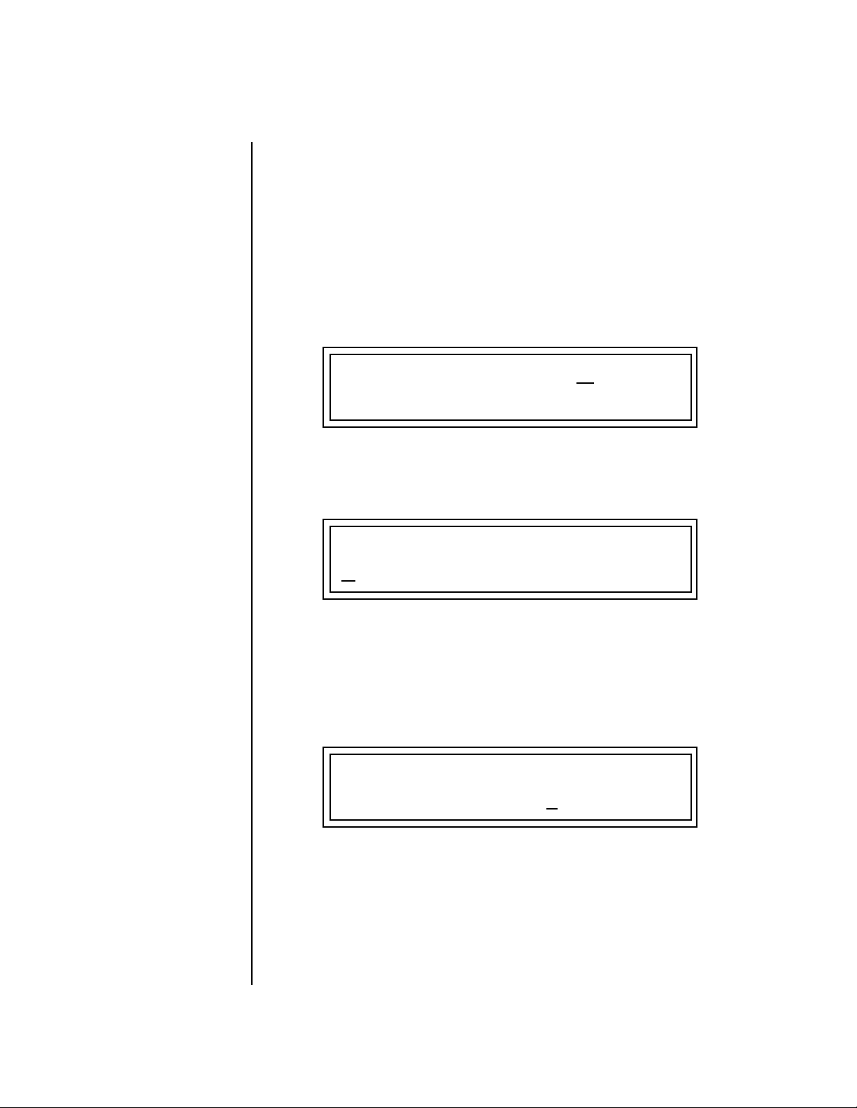
Instant Gratification
Exploring the Master Arpeggiator
Exploring the Master
Arpeggiator
XK-6’s multi-channel Pattern Generator/Arpeggiator is one of the greatest
features ever put in a synth. Let’s explore the Master Arpeggiator.
To Arpeggiate a Single Preset:
1. Select a preset. Note that the factory presets all have prefixes which
describe the type of sound. For this investigation it might be best to
choose a preset with the prefix “arp,” for arpeggiator. These presets are
optimized for use with the arpeggiator.
2. Set the Arp parameter in the main preset selection screen to “M” for
Master Arpeggiator.
C01 V127 P01R A:M XROM1
3
123
3. Press the Arp/Beats button in the Edit section of the front panel to
access the master Arpeggiator menu, then use the data entry control to
scroll to the screen shown below.
arp: OrbisTabula1
MASTER ARPEGGIATOR
S
tatus on
4. Make sure the arpeggiator Status is “on.” Play the keyboard to start
arpeggiating.
5. Press either cursor key repeatedly to move the cursor below the Status
field.
6. Turn the data entry control clockwise one click. The Mode screen
appears.
MASTER ARPEGGIATOR
Mode u
7. Use the cursor keys to move the cursor to the Mode field (up, down, up/
down, forw asgn, backw asgn, forw/backw, random, pattern). Try out
the different modes as you play the keyboard.
8. Move the cursor back to the lower left position and explore the other
parameters. The Note Value parameter changes the rate of the arpeggios.
By the way, note value is a divisor based on the Master Tempo. Try
changing the tempo, but come right back.
p
24 E-MU Systems
Page 35
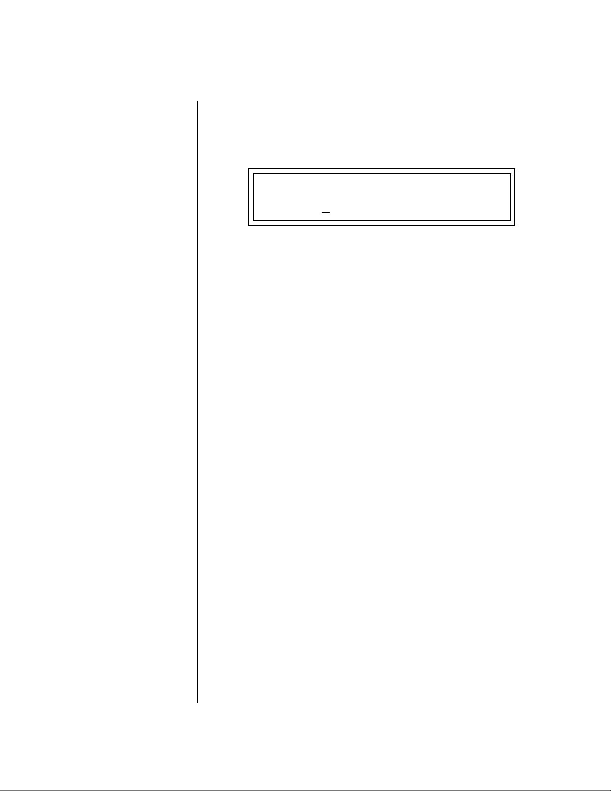
Instant Gratification
Exploring the Master Arpeggiator
9. Let’s check out the pattern generator. Go back to the Mode screen and
set the mode to “Pattern”.
10. Now advance to the Pattern screen (shown below) and move the cursor
to the Pattern Number field (the second field from the left).
MASTER ARPEGGIATOR
OO
OO
See the Arpeggiator
Chapter for detailed information
on creating Patterns.
Pattern 3
11. Try the various patterns. There are 200 permanent factory patterns and
100 user locations to store the patterns you create. Each pattern can
have up to 32 notes.
80 Inversions
XK-6 Owners Manual 25
Page 36
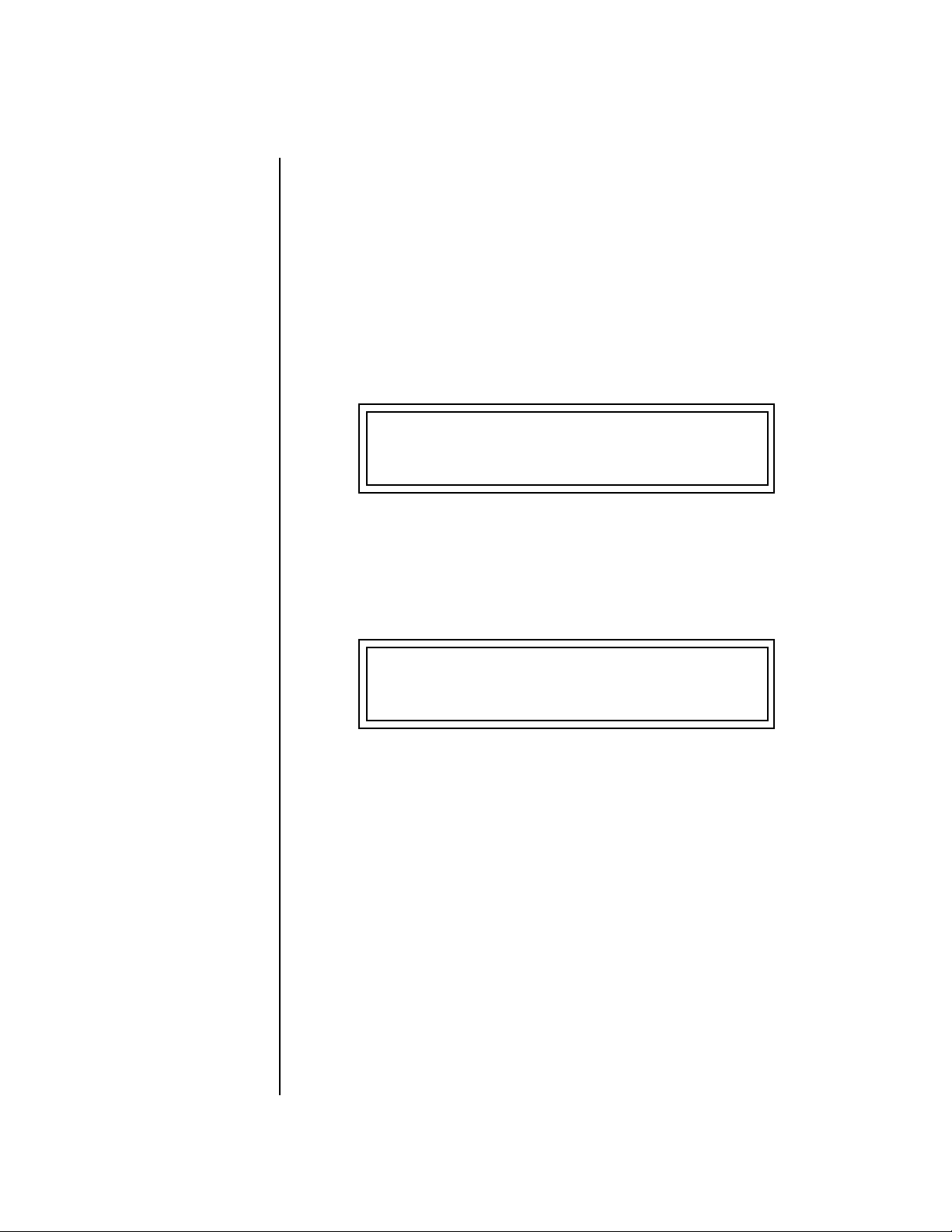
Instant Gratification
Multi-Channel Arpeggiator
Multi-Channel
Arpeggiator
XK-6 is totally amazing in its ability to run up to 16 arpeggiators at once!
Even two or three patterns at once can create very complex sequences and
dynamic landscapes of sound.
Here’s one way to access this ultra-powerful feature. There is one arpeggiator for each MIDI channel. First you’ll assign three of the Trigger Keys to
MIDI channels 01-03. Next, you’ll assign arpeggiator presets to these
channels. Then you’ll become addicted to this new way of making music.
Program the Trigger Keys
1. Press the Controllers button, then turn the data entry control until the
screen shown below appears.
TRIGGER BUTTONS FUNCTION
Play Beats Parts
2. Move the cursor to the lower line and turn the data entry control to
select “Play Note Events”. This sets the Trigger Buttons to play note
events instead of selecting Beats parts.
3. Move the cursor back to the top line and scroll to the screen shown
below.
T1 TRIGGERS Latch: on
Key:C3 Ch: Basic Vel: 064
4. Move the cursor until it is underneath the Latch field and turn Latch
mode On.
5. Move the cursor until it is underneath the Channel field (Ch) and set
the Channel to 01.
6. Move the cursor until it is underneath the Trigger field (T1) and
change the Trigger to T2 (trigger button 2).
7. Turn Latch On for trigger button 2 and set the channel to 02.
8. Change the Trigger to T3 (trigger button 3).
9. Turn Latch On for trigger button 3 and set the channel to 03.
Set up the Presets
10. Press the Main button (located beneath the Data Entry Control). The
preset select screen appears.
26 E-MU Systems
Page 37

Instant Gratification
Multi-Channel Arpeggiator
C01 V127 P00 A:P XROM1
026
11. Move the cursor underneath the Category field (as shown above) and
select the “arp” category.
12. Move the cursor underneath the preset name and select any “arp”
preset for channel 1.
13. Press the “+” Channel select button (located to the left of the LCD), so
that C02 is displayed.
14. Select any other “arp” preset for channel 2.
15. Select channel 03 and choose another arp preset.
Select Trigger Mode
16. Press the Selector Button in the upper left corner of the Command
Functions section. Pressing this button will switch between Track
Enable/Mute and Triggers mode. Select Triggers mode.
3
arp:Hollographik
OO
OO
Sometimes a simple
volume change will bring out
hidden voices and patterns.
Play it!
17. Now press Trigger Buttons 1, 2 and 3. You should be hearing three
arpeggiators playing at once.
18. Change the arp preset on the current MIDI channel. Since the cursor is
located on the preset name, all your selections will be in the arp
category.
19. Press the Channel button and change the arp presets for channels 1, 2
& 3. Since each factory preset has differently programmed arpeggiator
settings, changing the preset not only changes the sound, but the
arpeggiator as well.
20. You can also play the keyboard. You’ll be playing the preset currently
showing in the display.
21. Adjusting the front panel Controller Knobs modifies the preset
showing in the LCD.
22. Press the M-P button in the Controllers section to select the Arp control
functions. Adjust the Arp Velocity and Arp Gate Time. Then change
the MIDI channel and do it for another arp pattern.
23. Press the Mix button so that “VOLUMES” is selected. This screen lets
you blend the volume of every arpeggiator preset.
There’s lots more to the arpeggiators. To find out more, refer to the
arpeggiator chapter beginning on page 43.
XK-6 Owners Manual 27
Page 38

Multisetups save your
entire XK-6 setup. Find out more
on page 84.
Instant Gratification
Multi-Channel Arpeggiator
Time to Save?
If you want to SAVE everything exactly as it is, continue on.
1. Press the Multi button (located directly under the Data Entry Control).
2. Rotate the data entry control until you get to the menu shown below.
MULTISETUP NAME
User Setup
3. Press the right cursor button to move to the lower line.
4. Name your Multisetup so you can find it later, then press Enter.
5. Scroll to the next screen using the data entry control.
SAVE SETUP TO
002 User Setup
6. Move the cursor to the lower line, select a location and press Enter.
28 E-MU Systems
Page 39

Basic Operations
Basic Operations
CO1 A Vo l 1 27 P an00RSUER
0322bas: In ter fe rence
The XK-6 front panel contains an LCD screen, 38 buttons, and 4 real-time
controller knobs. Functions are grouped logically and the controls are
arranged for ease of use.
Power Switch The power switch is located on the rear panel next to the AC power
receptacle.
Volume Control This control is the master volume control for all audio outputs. The Volume
Control does not affect any editing or user interface operations.
The front panel volume control is a digital attenuator. For maximum
dynamic range, turn this knob all the way up and control the volume from
your mixer or amplifier.
Channel +/- Buttons These very handy buttons, located to the left of the LCD, serve as a shortcut
to increment or decrement the MIDI Channel (in Preset mode), Layer (in
Preset Edit mode) or Step Numbers (in Arpeggiator Edit mode).
Data Entry Control The data entry control is a stepped, variable control switch used to change
parameter values. The wheel increments or decrements the current value
one unit with each click. This control incorporates acceleration, which
advances the value faster if the data entry control is turned quickly.
XK-6 Owners Manual 29
Page 40
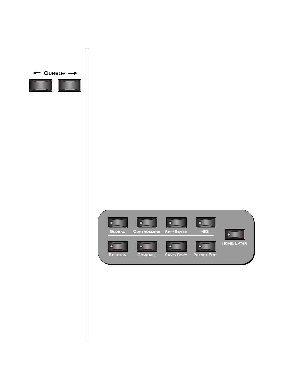
Basic Operations
Edit Section
Cursor Buttons These buttons, located just above the Data Entry Control, move the cursor
to the next parameter on the display. (The cursor is a little flashing line
underneath one of the parameters in the display.) Press either cursor button
until the cursor is underneath the desired parameter. The cursor buttons
have an auto-repeat feature which advances the cursor when the button is
held continuously.
The cursor can be moved bidirectionally using the data entry control while
either cursor select button is held down (for example, press and hold the
right cursor button and turn the data entry control).
Pitch & Mod Wheels These two controls, located to the right of the keyboard, are performance
expression controls. The left “Pitch Wheel”, is spring-loaded and is
normally used to bend the pitch up and down while playing. The center
position is off. The pitch bend range is set using the “Pitch Bend Range”
parameter in the Global menu (page 84).
The right “Mod Wheel” is programmed to add vibrato in most of the
factory presets. Like all the controllers in XK-6, the Mod Wheel can be
programmed to control any synthesizer parameter. See PatchCords on
page 102 and page 157 for more information.
Edit Section
Global Button The Global menu contains parameters that affect the entire machine. An
illuminated LED in the button indicates that you are in the Global menu.
For more information about the Global menu, see page 83
Controllers Button The Controllers menu contains parameters that are related to the front
panel controller knob and button triggers. An illuminated LED in the
button indicates that you are in the Controllers menu. For more information about the Controllers menu, see page 71.
30 E-MU Systems
Page 41
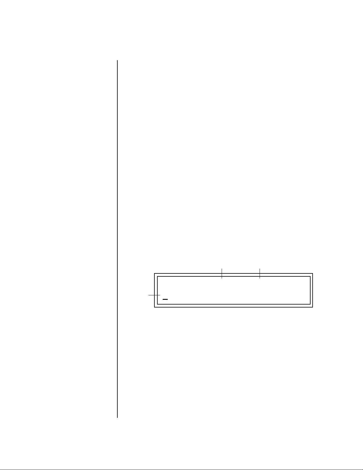
Basic Operations
Edit Section
Arp/Beats Button The Arpeggiator menu contains parameters that are related to Beats mode
and the Master Arpeggiator. Beats is a 16-track play-only sequencer that is
optimized for live performance and groove creation. An illuminated LED in
the button indicates that you are in the Arp/Beats menu. For more information about the Arp/Beats menu, see page 43.
MIDI Button The MIDI menu contains parameters that are MIDI related. An illuminated
LED in the button indicates that you are in the MIDI menu. For more information about the MIDI menu, see page 93.
MIDI Panic Button Pressing the MIDI and Home/Enter buttons simultaneously sends a MIDI
“All Notes Off” and “All Sound Off” for all 16 MIDI channels. This immediately kills all sounding notes internally and over MIDI.
Audition Button When the Audition button is pressed, the LED next to the button will
illuminate and a short “Riff” (programmed as part of the preset) will play.
The Riff is latched on and plays continuously until the button is pressed
again. Presets can be changed while Audition is latched on. See “Bank Select
Commands” on page 126 for more information on selecting banks via MIDI.
The top line of the Preset display changes to show the MIDI Bank Select
controller values needed to select the preset being auditioned. This handy
feature lets you know the exact Bank and Preset number.
LSB
XROM1
Preset #
MSB
Bank MSB:007 LSB:3
0
723 sfx: Slicer
Compare Button The Compare button allows you to toggle between an edited version of a
preset and the original, unedited version. When a preset has been edited,
the Save/Copy LED flashes. Press the Compare button, lighting its LED, to
hear the unedited preset. Press the Compare button again to hear the edited
preset. If edits are made to the preset while listening to the compared
original version, compare mode is aborted and the compare LED goes off.
Save/Copy Button The Save/Copy button is used to save changes to a preset, copy data
between presets, randomize presets and to move other types of data.
Selected groups of parameters, such as PatchCord settings, can be copied
between Presets and/or between Layers using this menu. The menu is
XK-6 Owners Manual 31
Page 42

Basic Operations
Real-time Controller Knobs
context-sensitive and will start at the appropriate save screen. See Save/
Copy on page 187 for more information.
The LED in the button illuminates to indicate that you are in the Save/
Copy menu. The LED also illuminates when any preset parameter has been
changed in the Preset Edit menu (or if the front panel knobs have been
moved with Quick-Edit mode enabled).
Preset Edit Button The Preset Edit menu allows you to create and edit presets. An illuminated
LED in the button indicates that you are in Preset Edit mode. For more
information about the Preset Edit menu, see page 129.
Home/Enter Button The Home/Enter button is dual purpose. In general, this button acts as the
“Home” button. For example, when in an Edit menu, this button snaps the
cursor to the page name field of the current screen. When viewing the
Preset Select screen, this button snaps the cursor to the preset number field.
The flashing green LED of the Home/Enter button indicates that pressing
the button will initiate a particular operation.
Real-time
Controller
Knobs
The Real-time Controller Knobs serve dual purposes. Knobs Preset Quick
Edit (page 79) can be enabled to use the knobs for editing in the Preset Edit
menu.
1. Quick Edit - Real-time control of internal synthesizer parameters and
“Quick Editing” the initial settings of the real-time controllers
2. Programmable Knobs - Real-time control of MIDI continuous
controllers on external synthesizers
32 E-MU Systems
Page 43

Knob Functions Quick Edit mode
The Real-time controller knobs provide direct control of the XK-6’s synthesizer parameters when the Controller Function Select is set to Quick Edit.
There is an LED next to each of the control knobs which illuminates to
indicate that the knob setting has been changed from the value
programmed in the preset (“Knobs Preset Quick Edit” mode must be
enabled in the Controllers menu). If the knob position is returned to the
original setting, the LED is extinguished.
OO
OO
Quick Edit knob
movements can be recorded into
an external sequencer.
Initial controller values can be stored in every preset. When you move a
knob with Quick-Edit enabled, the Initial Controller Value is updated with
the knob’s new value. The knob’s LED lights indicating that the preset value
has been changed. The MIDI A-P values are stored in the corresponding
Initial Controller Amount parameter in the Preset Edit menu (see “Initial
Controller Amount” on page 167). The Save/Copy button LED flashes to
remind you that the preset has been edited. “Quick-Edits” made to a preset
are lost if you select another preset before saving them.
The four rows of knobs always control the preset on the basic MIDI channel
(the channel showing on the preset select screen), when the control switch
is set to Quick Edit.
Basic Operations
Real-time Controller Knobs
The labels (Filter Cutoff, Filter Q, Filter Attack, Filter Decay, etc.) printed on
these rows show how the factory ROM presets are programmed to respond.
(The controls may not exactly conform to the front panel labels depending on the
preset.) You can change the way a preset responds to MIDI A-P messages
from the Preset Edit menu (PatchCords). The knobs only generate a
message when you move a knob to a new value. The current value jumps to
the new value.
To Quick-Edit a Preset:
1. Select Quick Edit mode using the Controller Function Select button.
2. Use the Control Knobs to change the sound of the current preset as
desired.
3. Press the Save/Copy button. You may have to turn the data entry
control so that the display reads, “Save PRESET to.”
4. Press the right cursor button to select the bottom row.
5. Optional: Select a new preset location if you don’t want to overwrite
the current preset, or if the current preset is a ROM preset.
6. Press the Enter button to save the preset.
XK-6 Owners Manual 33
Page 44

Basic Operations
Screen View Buttons
Screen View
Buttons
The Screen View buttons switch between three display modes.
Main This button instantly switches the display to the Main Screen shown below.
This screen is used for changing presets, changing MIDI channels and
setting the volume and pan positions for each MIDI channel. See page 37
for more information.
C01 V127 P01
A:off User
R
0793 kit: Hide & Seek
Multi This button switches the display to the Multisetup menu. A Multisetup is a
group of parameters that you might associate with a particular performance
setup or song. See page 41 for detailed information about Multisetups.
RESTORE MULTISETUP
000 User Setup
Mix Screen This button switches the display to the Mix screens (volume & pan). The
mix screens allow you view and adjust the volume and pan settings for all
16 channels. This is particularly useful when playing back a MIDI sequence.
The volume and pan settings for all 16 channels are saved with the Multisetup (page 41).
34 E-MU Systems
VOLUMES Chan: 01 Vol: 127
Page 45

Basic Operations
Screen View Buttons
PANS Chan: 01 Vol: 127
right
left
Demo Mode Pressing the Main and Mix buttons simultaneously calls up the Demo
Sequence page. XK-6 has several factory demonstration sequences that let
you hear what this incredible machine can do. The actual number of demo
sequences depends on which ROM sounds sets are installed.
DEMO SEQUENCES XROM1
Arctic Drift
To Play a Demo Sequence:
1. Press and hold the Main and Mix buttons at the same time to enter the
Demo Sequence page. The screen shown above appears.
2. Select a sequence using the data entry control. The Enter LED will be
flashing.
3. Press the Enter button to begin playing the selected sequence. The
following screen appears.
PLAYING: Arctic Drift
Press ENTER to stop
4. Press the Enter button again to stop playing the sequence.
5. When a demo sequence plays to the end, the next demo will automati-
cally begin playing. The screen will display the new demo name.
6. With the sequence stopped, press any other button to Exit demo
sequence mode.
XK-6 Owners Manual 35
Page 46

Basic Operations
Command Functions
Command
Functions
The Command Functions section serves multiple purposes which are listed
below.
• Beats Part enable/disable. See page 22.
• Assignable & latchable note triggers. See page 76.
• Preset select keys. See page 77.
• External preset select keys. See page 78.
• Preset Edit menu jump keys. See below.
Preset Selection When the preset selection LED is lit, the command buttons can be used to
quickly select sixteen of your favorite presets. In this mode, pressing one of
the comand buttons selects the preset you have assigned to the button.
See page 77 for more information.
Trigger Mode Select Triggers mode by pressing the mode select button so that the
“Triggers” LED is illuminated. Now the 16 buttons work like keyboard
notes. Each of the 16 buttons can be assigned to any MIDI note, on any
MIDI Channel (01-16), with any velocity (0-127), and can be set to be
latched or momentarily on. Latched note will hold until the button is
pressed again. Latched notes will be indicated by the LEDs. Trigger keys are
assigned from the Controllers menu. See page 76 for more information.
Preset Menu Jump Keys
Whenever you are in the Preset Edit menu, the sixteen command buttons
function as “jump” buttons to the various screens in the Preset Edit menu.
The jump location is labelled directly below each button.
Pressing a jump button instantly takes you to the first screen in the selected
category. Pressing the button again takes you to the second screen in the
category and so on. Repeated pressing will rotate you back to the first
screen in the category.
36 E-MU Systems
Page 47

Basic Operations
Main Screen
Main Screen The Main Screen is accessed by pressing the Main button located directly
under the data entry control. From this screen you can examine or change
the Preset, Volume, Pan Position and Preset Location for each of the 16
MIDI channels.
C01 V127 P01
0793 kit: Hide & Seek
MIDI Channel Selection
To Change the MIDI Channel:
1. Press the Main button to display the Main screen.
2. Press the Channel inc/dec buttons located to the left of the liquid
crystal display to select channels 01 through 16. The preset, volume
and pan settings for each channel will be displayed as you scroll
through the channels.
The channel number shown in the main screen is the “Basic MIDI Channel”
when in Omni or Poly modes.
Preset Selection To Change the Preset:
1. Press the Main button to display the Main screen.
2. Press either cursor key until the cursor is underneath the preset
number. (The cursor is a little flashing line underneath one of the
parameters in the display.) As you rotate the data entry control, the
preset number and name changes.
Bank Contents
0
128 RAM Presets
1
128 RAM Presets
2
128 RAM Presets
USERROM 1
3
128 RAM Presets
0
128 ROM Presets
1
128 ROM Presets
2
128 ROM Presets
3. The displayed preset is assigned to the displayed MIDI channel. Presets
are arranged into banks of 128, as shown in the diagram at left.
Bank Number
Preset
Number
C01 V127 P01
0793 bts: Logic
A:off User
R
A:off User
R
??
Depending on
ROM sets installed
Using the screen above as an example, the superscripted number 2 in the
second line of the display identifies the current bank number.
• Select banks independently of the of the preset number by locating the
cursor on the Bank field and turning the data entry control.
XK-6 Owners Manual 37
Page 48
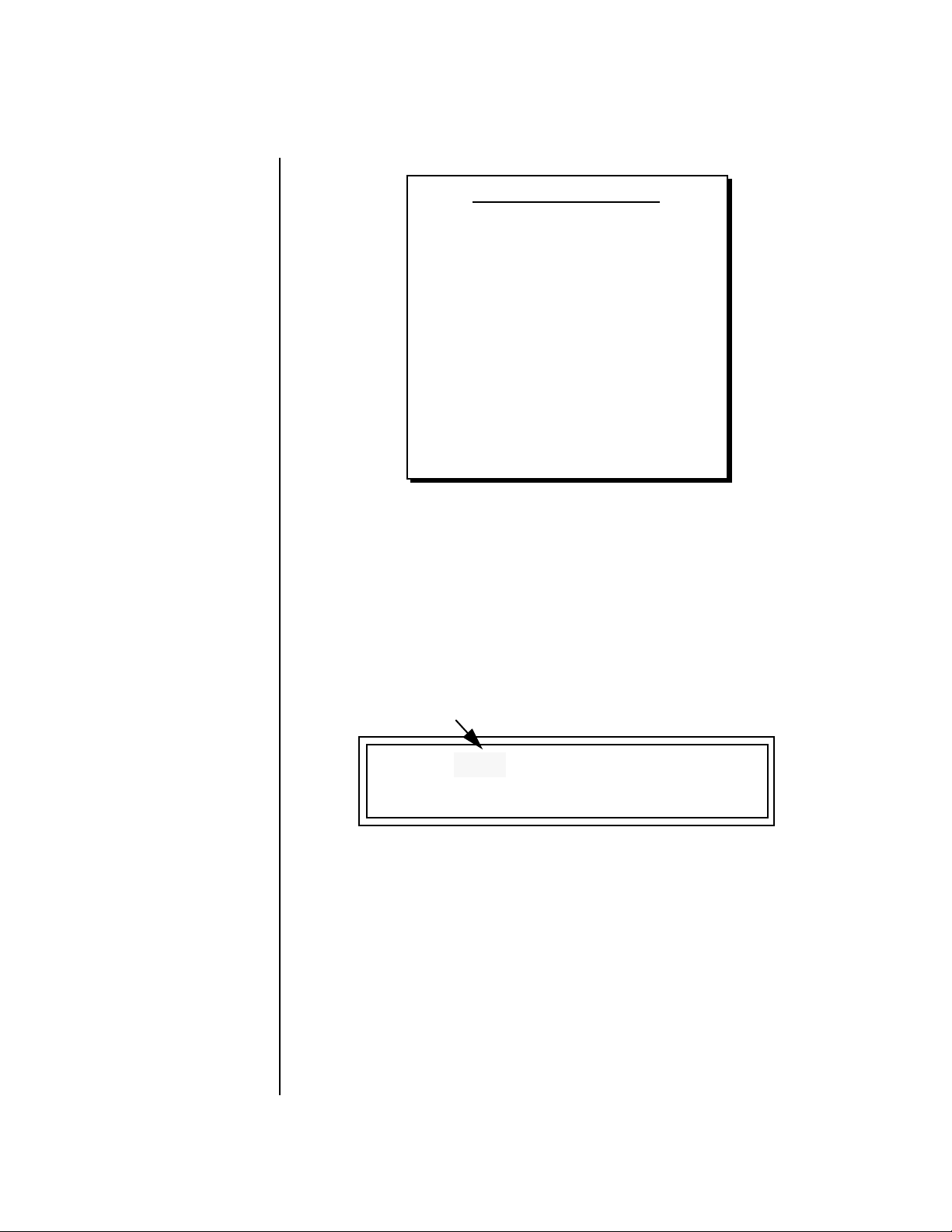
MIDI BANK SELECT
MSB LSB
cc00 cc32
Basic Operations
Main Screen
USER
USER
USER
USER
XROM1
XROM1
XROM1
XROM1
This chart shows the MSB and LSB numbers needed to select preset banks over MIDI.
Select a bank, then send the program change number. Without a bank select command,
presets are selected from within the current bank.
00
00
00
00
07
07
07
07
00
01
02
03
00
01
02
03
Bank 0
Bank 1
Bank 2
Bank 3
Bank 0
Bank 1
Bank 2
Bank 3
Channel Volume Channel Volume sets the volume of the selected MIDI channel in relation
to the other channels. This is the same parameter as MIDI volume control
#7, and changes made over MIDI are shown in the display.
Volume
38 E-MU Systems
C01 V127 P01
A:off User
R
0793 bts: Logic
To Change the Channel Volume:
1. Press the Main button to display the Preset Select screen.
2. Press either cursor key until the cursor is underneath the volume value.
3. Rotate the data entry control to select a volume level. The Channel
Volume range is 000-127.
Page 49

Basic Operations
Main Screen
Channel Pan Channel Pan sets the stereo position of the selected MIDI channel. This
control operates like the balance control on your home stereo system.
Channel Pan is the same parameter as MIDI pan controller #10, and
changes made over MIDI are shown in the display.
Pan Position
C01 V127 P01R A:off User
0793 bts: Logic
Note: Pan settings in the preset ADD algebraically with the Channel Pan
setting. Therefore, if the pan setting in the preset were set to “63
the Channel Pan setting full left would return the sound to the center
position.
To Change the Channel Pan:
1. Press the Main button to display the Preset Select screen.
2. Press either cursor key until the cursor is underneath the pan field.
3. Rotate the data entry control to select a pan value. 64L indicates a hard
left pan, 63R indicates a hard right pan. With a setting of “00,” the
sound is centered in the stereo field.
R,” moving
Channel Arpeggiator This function controls the arpeggiator for each MIDI channel. When the
channel arpeggiator mode is set to Off, then there is no arpeggiation on
that channel, regardless of what is set up in the Master Arpeggiator or
preset. If the channel arpeggiator is On, the preset’s arpeggiator is used,
regardless of whether or not it is turned on in the Preset Edit menu. This
lets you turn on arpeggiation from the main screen.
If the mode is set to “P” (for preset), the preset’s arpeggiator settings and
on/off status is used. If the mode is set to “M” (for master), the master
arpeggiator settings and on/off status (located in the Arp menu) are used.
See the “Arp/Beats Menu” on page 43 for more information.
To Play the Arpeggiator (Quick Start):
1. From the Main screen, press either cursor key repeatedly until the
cursor is underneath the arpeggiator field (A:).
2. Rotate the data entry control to select “P” for preset.
3. Press either cursor key repeatedly until the cursor is underneath the
Preset Category field and select “arp:” using the data entry control.
4. Press the right cursor button to move it to the Preset Name field.
5. Play notes or chords on the keyboard. Change presets as desired to
audition the various patterns and presets.
XK-6 Owners Manual 39
Page 50
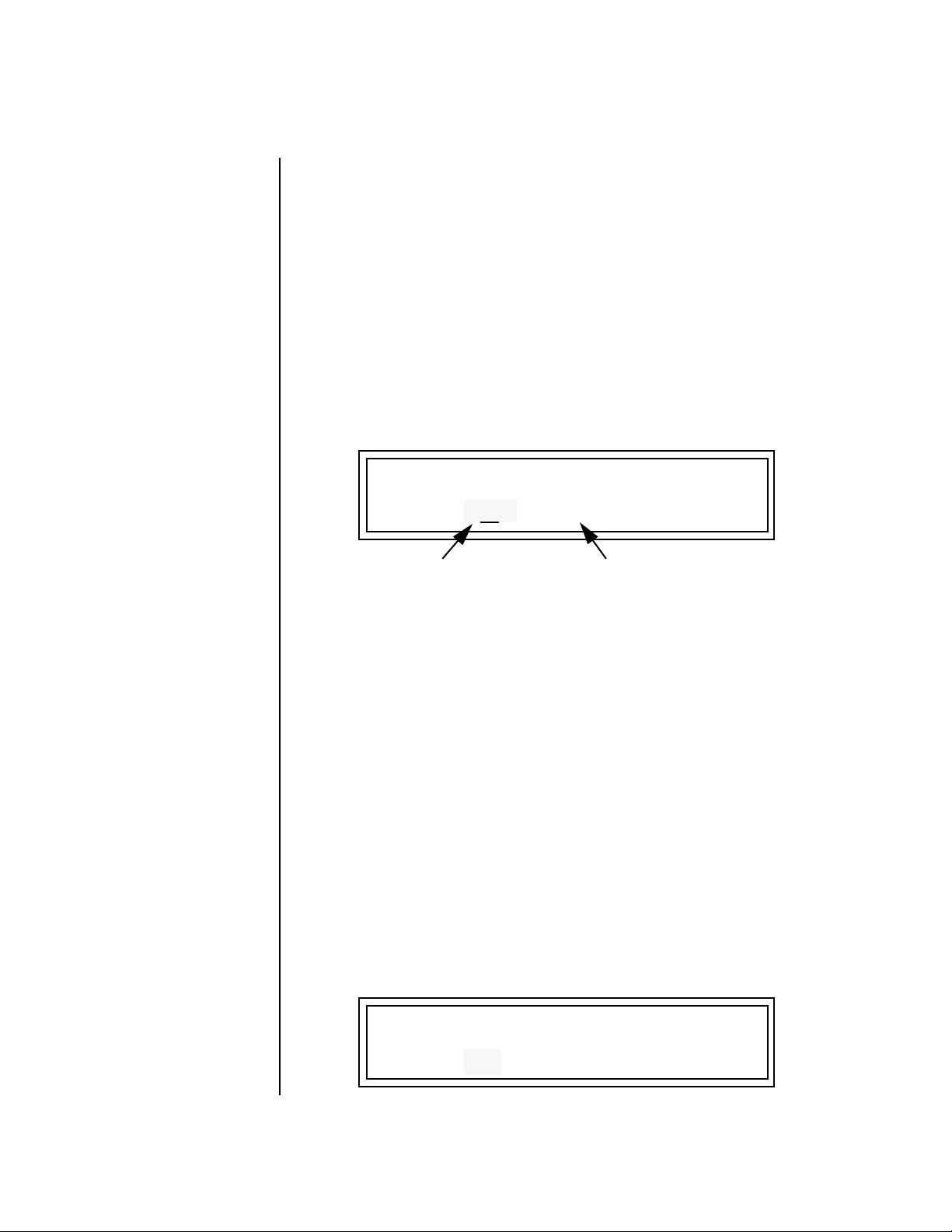
Basic Operations
Sound Navigator
Sound
Navigator
Sound Navigator allows you to search through preset and instrument
categories to find the type of sound you’re looking for. Each preset and
instrument has a name and a three letter preset category. You can create
your own categories in order to group favorite presets. The preset category
is assigned in the Preset Edit menu (Preset Name). Instrument categories are
fixed.
Preset Category When you want to find presets in a particular category, you simply change
the category field in the Main screen, then move the cursor to the preset
name field to scroll through all the presets in the selected category.
When the cursor is on the Preset Category field, turning the data entry
control selects different preset categories. The Name Field will change to
show the first preset in each category.
C01 V127 P00
A:off User
0641 w al: Raverotic
Preset Category
To Change the Preset Category:
1. From the Main screen (shown above), press either cursor key repeatedly
until the cursor is underneath the preset category field.
2. Rotate the data entry control to select one of the preset categories.
Preset Categories are displayed in alphabetical order.
Preset Name
To Select a Preset within a Category:
1. After selecting a category, move the cursor to the Preset Name field.
2. Rotate the data entry control to scroll through the presets in the
selected category. Note that the preset numbers will no longer change
sequentially.
Instrument Category When the cursor is on the Instrument Category field (Preset Edit menu),
turning the data entry control selects different instrument categories. The
Name Field changes to show the first instrument in each category. Move
the cursor back to the instrument name to choose other instruments in the
selected category.
L1
INSTRUMENT ROM:XROM1
0641 wal: Raverotic
40 E-MU Systems
Page 51

Basic Operations
Multisetups
Multisetups A Multisetup is a group of parameters that you might associate with a
particular performance setup or song. It is like a “snapshot” of the current
configuration of the XK-6. There are 64 setups numbered 0-63. All the
Multisetups are user programmable except 63, the factory setup.
A Multisetup includes ALL the following parameters:
• Preset/Volume/Pan/Arp assignments for each of the 16 MIDI channels.
• Multisetup Name
• ALL Controllers menu parameters
• ALL Global Menu parameters, except…
User Key Tuning Tables
• ALL Arp Menu parameters, except…
User Arp Patterns
• ALL MIDI Menu parameters, except…
MIDI Program Change->Preset Map
When a Multisetup is selected, it overwrites the current Preset/Vol/Pan/Arp
selections on all MIDI channels. It also overwrites the Controllers, Global,
Arp, and MIDI menu parameters (with the exceptions noted above).
Restoring Multisetups
If you make changes to any of these menus, XK-6 will retain the changes,
even if power is turned off. They are of course, overwritten when you
restore a Multisetup.
XK-6 contains 64 Multisetup locations. These are all User locations except
location 63, which is a factory defined Multisetup.
Multisetups can be restored using a MIDI Bank Select command.
Select: cc00 = 80, cc32 = 00, (dec) then send a Program Change command
corresponding to the Multisetup you wish to select.
RESTORE MULTISETUP
0
03 Jazzercide
To Restore (Select) a Multisetup:
1. Press the front panel Multisetup button (below the Data Entry Control).
2. Scroll to the Restore Multisetup screen using the data entry control. The
menu page most recently selected since powering up XK-6 will be
displayed. The cursor appears below the first character of the screen
heading on line one.
XK-6 Owners Manual 41
Page 52
Basic Operations
Multisetups
3. Press either cursor button to move the cursor to the bottom line of the
screen.
4. Now, use the data entry control to select a Multisetup. The Enter LED
will be flashing.
5. Press the Enter button to load the selected Multisetup.
Multisetup Name
Saving Multisetups
Multisetups can be named to make it easier to remember their purpose.
1. Scroll to the “Setup Name” screen (shown below) using the data entry
control.
MULTISETUP NAME
020
User Setup 23
2. Press either cursor button to move the cursor to the bottom line of the
screen.
3. Change the characters using the data entry control. Change the cursor
position using the cursor buttons.
4. Press Enter or move the cursor to the top line when you’re finished
naming the multisetup.
To Save a Multisetup:
1. Set the Preset, Volume, Pan and Arp settings (in Main mode) for all
channels. Set the Global, MIDI, and Controllers menu parameters the
way you want them.
2. Press the Multi button, then scroll to the “Save Setup” screen (shown
below) using the data entry control.
42 E-MU Systems
SAVE SETUP TO
Destination Multisetup
020
3. Press either cursor button to move the cursor to the bottom line of the
screen.
4. Now, use the data entry control to select the destination location. The
Enter LED will be flashing.
5. Press the Enter button to save the Multisetup.
Page 53

Arp/Beats Menu
Arp/Beats Menu
XK-6’s Beats mode allows you to trigger, latch and unlatch synced loops
and grooves from separate keys on your keyboard. Simply select a bts:
preset and play the 16 trigger keys to bring specific Parts in and out. This is
Macro-Music!
XK-6 can also run up to 16 simultaneously synced arpeggiators, each with a
different preset sound. The arpeggiators can either play one of 7 chord
arpeggios or can be set to play a pattern, which is a stored sequence of
notes. Combined with Beats, the sheer number of musical permutations is
staggering!
To enable the Arpeggiator/Beats menu:
Press the Arp button, lighting the LED. The Arp screen displays the menu
page most recently selected since powering up XK-6. The cursor appears
below the first character of the screen heading on line one.
Arp parameters are
automatically saved to the
current multisetup when you exit
the menu, but you may wish to
save to another location.
If another Multisetup is
“Restored” any unsaved
changes will be lost if you
haven’t saved the Multisetup.
To select a new screen:
Press the Home/Enter button or press the Cursor button repeatedly until
the cursor is below the screen title heading on the top line of the display.
Rotate the data entry control to select another screen.
To modify a parameter:
Press either Cursor button repeatedly (or hold down the right cursor button
while turning the data entry control) until the cursor is below the desired
parameter value. Rotate the data entry control to change the value.
To access a submenu:
The Master Arpeggiator screens have submenus which are accessed by
pressing the cursor buttons to move the cursor to the lower left corner of
the display. Select the submenu function using the data entry control.
To save Arpeggiator parameters:
Press the front panel Multi button and scroll to “Save Setup To”. Select a
Setup number and press Enter. See “Saving Multisetups” on page 42.
To return to the previously selected Mode/View screen:
Press the Arp/Beats button, turning off the LED.
XK-6 Owners Manual 43
Page 54
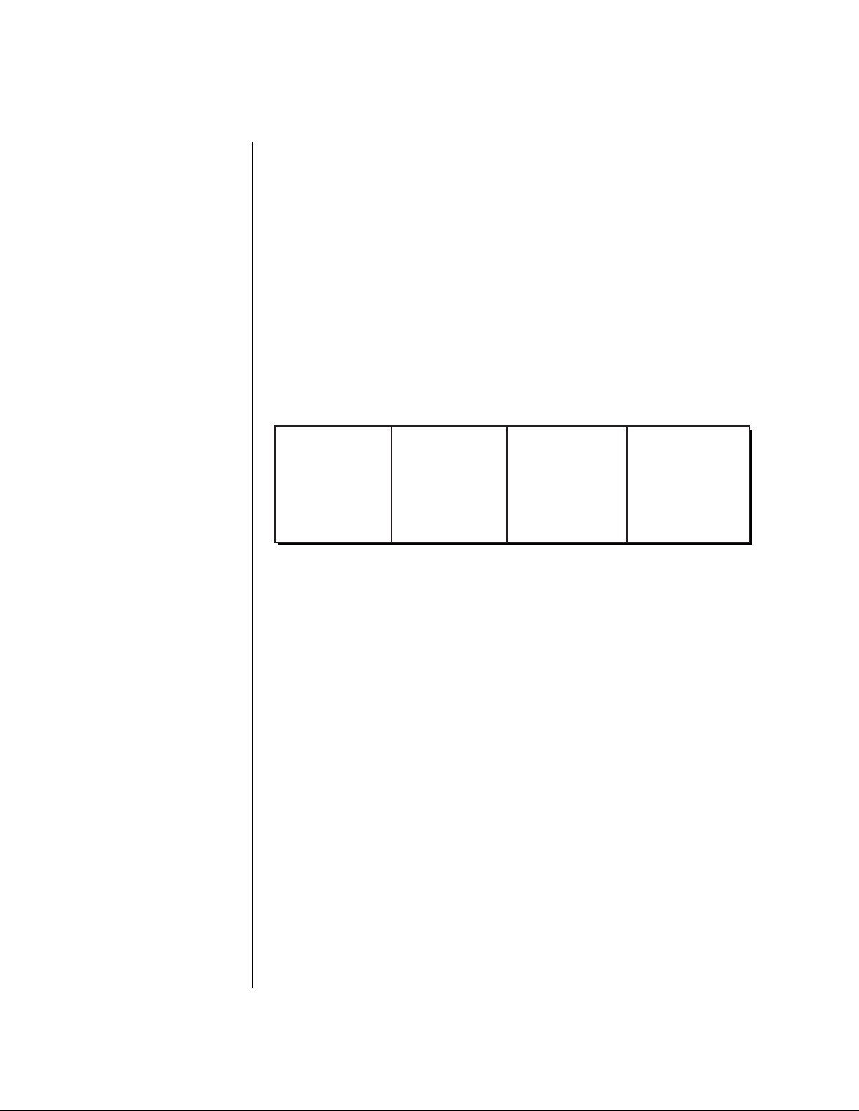
Arp/Beats Menu
Beats
Beats XK-6 contains a 16-track play-only sequencer that is optimized for live
performance and groove creation. XK-6 contains dozens of special 16-part
Beats Riffs created by some of the best producers in the business. Beats Riffs
are normally used in conjunction with a “bts:” preset containing the appropriate percussion mapping, but any preset can be selected and used.
The Beats channel is selected from the Beats enable screen in the Arp/Beats
menu.
Here’s how it works. Each of the 16 parts is assigned to a trigger key on the
selected Trigger MIDI channel. Each part is brought in or out by pressing
that key. Keys can also be Latched (press the key once to turn the part on, press
it again to turn the part off). Other control keys allow you to Mute All Parts,
Clear All Parts, and Start & Stop the beat. The 16 parts are arranged in the
following manner:
__
__
Beats (bts:) Riffs are
special 16-part riffs made
especially for use with Beats
mode. A Riff without the bts:
prefix only has Part 1 recorded.
OO
OO
By assigning Trigger
Buttons (page 76) to the
keyboard Beats Layout Keys, you
can trigger Beats and MIDI notes
using the Trigger buttons.
Main Groove
1. Kick1
2. Snare1
3. Hihat1
4. Perc1
For each Beats Riff, you have 2 Grooves, 4 Fills which correspond to the
four parts of the Main and Alternate groove, and 4 Instrument parts. By
adding and removing parts, you control the complexity of the groove.
Each part can also be scaled by Key Velocity, allowing you to fade parts in
and out (if velocity is routed to volume) as you play, or can be Transposed
over a six octave range.
Each part can be assigned to any one of four Groups, which allow multiple
parts to be triggered from a single key. You can only access Groups using
the keyboard trigger keys. See the Factory Setup diagram on the next page.
Trigger layouts are saved with the Multisetup.
Alt. Groove
5. Kick2
6. Snare2
7. Hihat2
8. Perc2
Perc / Fills
9. Perc3/Fill1
10. Perc4/Fill2
11. Perc5/Fill3
12. Perc6/Inst.
Instr/Wild
13. Inst1/Wild1
14. Inst2/Wild2
15. Inst3/Wild3
16. Bass
44 E-MU Systems
Page 55

Clear Parts
Trig. Hold
C-2
Factory Setup
Multisetup 63
Perc 1
Snare 1
C-1 C0
HiHat 2
Perc 3/Fill 1
Perc 5/Fill 3
Inst 2/Wild 2
Inst 4/Wild 4
Group 3
Arp/Beats Menu
Beats
Main
Groove
Alternate
Groove
OO
OO
Starting Beats mode
with the Start/Stop key allows
you to start the sequencer rolling
silently. Then you can bring Parts
in and out using the “Busy”
control.
OO
OO
If Mute is set to 1-bar,
the Part mutes for 1 bar then
un-mutes.
Mute
Start/Stop
The chart above shows the Factory Multisetup assignment of each Part, the 4 Groups and
the Control Keys. These assignments can be modified to suit your personal preference,
then saved in one of the Multisetup locations.
• Start/Stop Trigger Starts the beat sequencer from the beginning of
• Clear Parts Clears any enabled parts. This control provides a
• Mute Mutes all Parts while held, but the Beats sequencer
• Trig Hold When this key is held, all other Trigger Keys
Kick 2
Kick 1
HiHat 1
the sequence. When latched, pressing once starts
and pressing again stops. When unlatched, the
sequence runs as long as the key is held.
Once the Beats sequencer is started, it continues to
run even if no triggers are active.
Start/Stop doesn’t clear latched parts when it stops
the sequencer. Any trigger played after stopping
will not only start the sequencer and play that trigger's part, but also play all previously latched parts.
quick and easy way to shut off all latched Parts.
Latch mode has no effect on this key.
continues running.
behave as if they were in Latch mode.
Perc 2
Snare 2
Perc 4/Fill 2
Group 1
Group 2
Perc 6/Fill 4
Inst 1/Wild 1
Inst 3/Wild 3
Group 4
XK-6 Owners Manual 45
Page 56

Arp/Beats Menu
Beats Mode
The Beats sequencer plays as long as any Beats triggers are active. Beats Riffs
can also be Restarted using a MIDI Song Start command even if the Beats
channel is not currently selected. The Audition LED illuminates whenever
the Beats sequencer is running (even if no Parts are playing).
Pressing the Audition button or starting a Demo causes the Beats sequencer
to stop. Pressing the Audition button plays selected Parts on “bts:” presets.
All Arp/Beats parameters are saved with the Multisetup. (See “Multisetups” on page 41 for more information.)
Beats Mode This screen turns Beats mode on and has several other features which allow
flexible control over Beats mode. There are several status modes that
determine when Beats will be turned on and which Riff will be used.
Beats and BEAT Triggers can be set to different MIDI channels. This allows
you to perform on two MIDI channels at once with a keyboard that only
transmits on a single MIDI channel.
The Basic Channel is the
MIDI channel currently displayed
in the Main Screen.
BEATS MODE Status: P
BtsCh: Basic TrigCh:Basic
Status
• Off . . . . . . . Beats mode off.
• On . . . . . . . . Beats mode on. The Riff assigned in the preset is used.
• P . . . . . . . . . Beats mode is turned on ONLY if the Riff assigned in the
preset is a “bts:” riff. The Riff assigned in the preset is used.
(Default setting)
• M. . . . . . . . . Beats mode on. The Master Riff is used (Arp/Beats menu).
BEATS MODE Status: P
BtsCh: Basic TrigCh:Basic
Beats Channel (BtsCh)
• 01-16 . . . . . Selects the MIDI channel on which Beats play.
• Basic . . . . . . Beats play on the MIDI channel displayed in the Main Screen.
46 E-MU Systems
Trigger Channel (TrigCh)
• 01-16 . . . . . . . Selects the MIDI channel on which Trigger Keys will be active.
• Basic . . . . . . . . Sets the Trigger Keys to the MIDI channel displayed on the
Main Screen.
Page 57

__
__
If you don’t select a
“bts:” preset, only the first
trigger key will work.
Arp/Beats Menu
Beats Mode
Beats Setup:
Set the Trigger Buttons to Beats Mode
1. Press the Controllers button on the front panel.
2. Turn the data entry control clockwise until you fin the “TRIGGER
BUTTONS FUNCTION” screen.
3. Set the lower line of the display to read, “Play Beats Parts”.
4. Press the Controllers button on the front panel again to exit the menu.
Set the Trigger Buttons to be Triggers
5. Press the Triggers button in the Command Functions section of the
front panel. OK, now you’re ready to start playing Beats.
Playing Beats:
Selecting Beats Presets
1. Press the right cursor button twice so that the cursor is located
beneath the Category field.
Riffs marked “bts:” have 16
parts. Riffs without “bts:” have
only 1 part.
2. Turn the data entry control until bts: is shown in the Category field.
3. Press the right cursor button so that the cursor is underneath the
Preset Name field.
4. Now turning the data entry control selects ONLY bts: presets!
Play Beats
5. Press any of the sixteen front panel Trigger Buttons. Notice that each
button brings in a specific part. The chart below shows which buttons
control which part in bts: presets.
Main Groove
1. Kick1
2. Snare1
3. Hihat1
4. Perc1
6. Also notice that the Audition LED comes on when Beats begin playing.
Alt. Groove
5. Kick2
6. Snare2
7. Hihat2
8. Perc2
Perc / Fills
9. Perc3/Fill1
10. Perc4/Fill2
11. Perc5/Fill3
12. Perc6/Inst.
Instr/Wild
13. Inst1/Wild1
14. Inst2/Wild2
15. Inst3/Wild3
16. Bass
Beats are simply multitrack Audition Riffs. You can use the Audition
button to turn Beats on and off.
7. Try out a few different bts: presets.
Get Busy!
Two of the Controller knobs are programmed to control Beats. Check it out!
8. Press the M-P button in the Controllers section. Its LED will light.
XK-6 Owners Manual 47
Page 58

Arp/Beats Menu
Beats Mode
9.
Now turn the Mod 1 knob with a Beats Riff playing. Mod 1 is controls
the Beats Busy parameter which adds or subtracts parts from the Beat.
10. Turn the Mod 2 knob with a Beats Riff playing. Mod 2 is controls the
Beats Variation parameter. Beats Variation changes which parts are
playing without changing the number of parts. This makes it easy to try
out different combinations of Beat Parts.
To Play Beats on a different MIDI channel:
Beats can be assigned to a certain MIDI channel while you play the
keyboard on another channel. (Make sure you have Beats mode set up correctly
as described in “Beats Setup” on page 47.)
1. Press the Arp/Beats button. The screen shown below appears.
BEATS MODE Status: P
BtsCh: Basic TrigCh:Basic
OO
OO
Wrong FX? In Omni
mode, the FX assigned to
channel 2 will be used. In Multi
mode, the Master FX settings
will be used. See pages 88 & 98.
2. Set the Beats Channel (BtsCh) to 01.
3. Select any bts: preset on channel 1 (main screen).
4. Press any of the sixteen Beats buttons to start your Beat playing. (Do
NOT start Beats by pressing the Audition button.)
5. Press the + Channel button to the left of the LCD to select channel 2.
6. Select a preset to jam along with the Beat.
7. The Trigger Keys now play Beats and the other keys play the preset on
channel 2.
8. The Audition button can be used to turn the Beat off. (If you try to use it
to turn Beats on while on channel 2, the Riff on channel 2 will play.)
48 E-MU Systems
Page 59
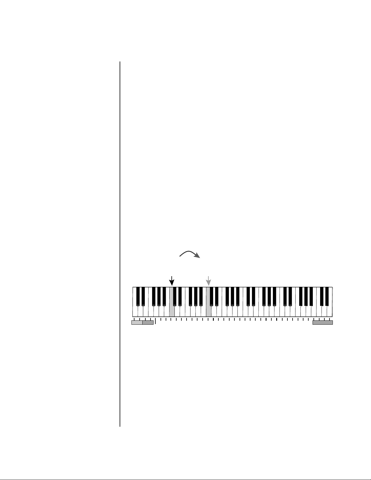
Arp/Beats Menu
Beats Controllers
Beats Controllers Beats can be controlled using the front panel real-time controllers or
external MIDI continuous controllers. Controllers are patched to Beats
via the Preset PatchCords located in the Edit menu. The following Preset
PatchCord destinations control Beats.
Beat Velocity Group 1-4 (BtsVelG1 -> BtsVelG4)
Parts assigned to one of the four Beats groups can have their velocity scaled
by the controller input. Since most “bts” presets have velocity controlling
volume, this control can be used to mix the relative levels of the Groups.
Beats velocity works as a percent addition. An input value of 0 (or no Cord)
means change the velocity by 0%. A full scale modulation setting of 100%
in the PatchCord adds 100% to the velocity value 100% + 100% = 200%. A
PatchCord setting of -100% subtracts 100% from the velocity (making it 0).
Beat velocity scalings are reset with a preset change.
Beat Xpose Group 1-4 (BtsXpsG1 -> BtsXpsG4)
Parts assigned to one of the four Beats groups are transposed by the
controller input. Transpose works by shifting the keyboard position and
not by changing the tuning of individual notes. Therefore, on a Beats
presets (bts), where different instruments are assigned to each key,
Transpose has the effect of changing the instrument used by a particular
part. This control ADDS to the Part Transpose set in the Beats Transpose
screen (page 53). Beat transpose offsets are reset with a preset change.
The Mod 1 controller
knob is assigned to Beats Busy.
Original
Part
Kick Crowd
Fun Scratch
Tick
909 Click
Machine Kick
Kick
Transposed
Snare
909 Tom
808 Snare
Simmons Tom
+12
909 Tom
909 Tom
Tom Wave
Waver Tom
Cymbal
Ride Cymbal
Splash Cymbal
Splashy Cymbal
Timbale 3
Bongo Tip
Low Conga
Bongo Tone
Ride Cymbal
Guiro
Guiro
Guiro
Cabasa
Wood Block
Agogo Hi-Tone
Wood Block
Triangle Mute
Triangle Open
Beat Busy (BtsBusy)
This destination determines which parts are enabled. Beat Busy will accept
either positive or negative values.
• Positive values Add parts to whatever parts are triggered
• Negative values Remove parts that are triggered.
XK-6 Owners Manual 49
Page 60

Arp/Beats Menu
Beats Controllers
OO
OO
A PatchCord amount of
50% is enough to drive Beat
Busy to the maximum setting.
OO
Hot Tip!
OO
The Bidirectional Mod Wheel:
Set Mod Wheel to BtsBusy with a
Cord amount of +100, then add
a DC bias to BtsBusy with a Cord
amount of -50. Wheel now adds
or subtracts “Busyness”.
Suppose the pitch wheel (which can output both positive and negative values)
were connected to Beat Busy and four Key Triggers are down. As the pitch
wheel is moved from center to fully up, the remaining parts will be enabled
until the pitch wheel is fully up and all parts are playing. Moving the pitch
wheel from center to fully down, the four triggered parts are sequentially
removed until at the most negative position of the wheel, no parts are
playing.
The Busy control acts on the Beats condition whenever the control is
changed. Playing more triggers without changing the Busy control simply
adds them until the Busy control is changed again, at which point it will
possibly add or subtract parts as needed.
The interaction between the Busy control, Triggers, Part Velocity and Group
Velocity can get complicated, but works according to this rule:
WHICHEVER CONTROL WAS LAST CHANGED TAKES OVER
When interacting with the Group Velocity scale control, the Busy control
ignores group velocity even when it is set to zero, enabling and disabling
parts as necessary. If the Group Velocity is changed after the Busy control, it
takes control, scaling parts as it deems necessary.
OO
OO
Cool Tip! Connecting
Key Pressure to Beat Busy at
50% increases BEAT complexity
the harder you press.
The Mod 2 controller
knob is assigned to Beats
Variation.
The Busy control does take the Part velocity into account when adding and
subtracting parts. If a part has a velocity of 0%, it is removed from the list of
parts that the Busy control adds or subtracts. Therefore, you can use the
Part Velocity control to remove parts you don’t want to hear.
Brings in Parts
Beat
Busy
Removes Parts
Played
Positive controller values bring in new Parts and negative controller values remove
Parts that are latched or held. In this example, the Pitch Wheel is connected to
Beat Busy since it outputs negative as well as positive values.
Beat Variation (BtsVari)
Beat Variation varies which Parts are brought in and out using the Beat
Busy control. Increasing this control mixes up the order in which Parts are
brought in and out, thus providing even more permutations to the Beat.
50 E-MU Systems
Page 61

Arp/Beats Menu
Beats Keys Layout
Beats Keys Layout This screen assigns the Beats triggers to keyboard notes on the Beats
channel. For each Part, Group and Control Key you can select the following
options:
__
__
Save your Beats Keys
Layouts and all other Arp/Beats
parameters using “Save Setup”
function in the Multisetup
menu.
• Key . . . . . . . . . Selects which keyboard key triggers the Part
• Latch . . . . . . . . The first key press turns the Part on, the next turns it off.
• Unlatch . . . . . . The Part plays only while the key is held.
• 1-bar . . . . . . . . The Part plays for one bar then stops.
BEATS KEYS LAYOUT
Part 1 Key: C1 unlatch
1-Bar Trigger Option
The 1-bar option requires a bit of explanation. When a trigger key is pressed
before the last beat of the measure, the part will continue playing until the
end of the measure. If the Trigger Key is pressed after the last beat of the
measure, the part waits until the next measure before playing. Then it plays
for the entire measure and stops. The time signature and the measure
bounds are determined by the particular Beats Riff you are playing.
Trig Key
pressed before
the last beat
12341234
Measure 1
Trig Key
pressed
here
12341234
Measure 1
Part continues
to end of measure
then stops.
Measure 2
Part begins at
next measure and
plays entire measure
Measure 2
XK-6 Owners Manual 51
Page 62

Arp/Beats Menu
Beats Keys Offset
Beats Keys Offset This function slides the Beats Trigger keys (assigned in the previous screen) up
and down the keyboard. This makes it easy to change the keyboard location
of the trigger keys without having to re-assign each key. A positive offset
moves the group of triggers up the keyboard by the designated number of
keys. Negative offsets move the trigger group lower on the keyboard.
BEATS KEYS OFFSET
+000 keys
Positive OffsetNegative Offset
Trigger
Keys
Beats Keys Offset slides the entire group of beats triggers up or down the keyboard.
Beats Part Velocity Each note of a Beats Riff can have its recorded velocity scaled by a value
(from 0 to 120%) of the recorded velocity or the actual played velocity of
the trigger key can be used (trigger vel). For example, if a note’s velocity is
80, scaling by 110% will increase the note’s velocity to 88. This feature
allows you to control the mix of the different parts in advance or “on-thefly” as you play. If a part’s velocity is set to 0%, that part will be removed
from the mix.
Select Part
P1
BEATS PART VELOCITY
Scaled by: trigger vel
To Set the Velocity for each Part:
1. Press the left cursor button to move the cursor under the Part field.
2. Select the Part number using the Data Entry Control. Parts 1-16 can be
selected. (All parts, shown as an “A”, can be edited at once if “Edit All
Layers” is enabled in the Master menu.)
3. Move the cursor to the bottom line using the cursor keys and adjust the
Velocity Scaling percentage using the Data Entry Control.
4. Repeat steps 1 through 3 for all the Parts you wish to adjust.
5. Press the Enter/Home button or use the cursor keys to move the cursor
back to the screen heading.
52 E-MU Systems
Page 63

Arp/Beats Menu
Beats
Beats Part Transpose Each Part of a Beat Riff can be transposed up to 36 semitones up or down.
Transpose works by shifting the keyboard position and not by changing the
tuning of individual notes. Therefore, on a Beats preset (bts:), where
different instruments are assigned to each key, Transpose has the effect of
changing the instrument used by a particular part. On a preset where a
single sound covers the entire keyboard, Transpose will actually transpose
the sound.
Select Part
P1
BEATS PART TRANSPOSE
+00 semitones
To set the Transposition for each Part:
1. Press the left cursor button to move the cursor under the Part field.
2. Select the Part number using the Data Entry Control. Parts 1-16 can be
selected. (All parts, shown as an “A”, can be edited at once if “Edit All
Layers” is enabled in the Master menu.)
3. Move the cursor to the bottom line using the cursor keys and adjust the
Transposition in semitones using the Data Entry Control.
4. Repeat steps 1 through 3 for all the Parts you wish to adjust.
5. Press the Enter/Home button or use the cursor keys to move the cursor
back to the screen heading.
Original
Part
Kick Crowd
Fun Scratch
Tick
909 Click
Machine Kick
Kick
Transposed
Snare
909 Tom
808 Snare
Simmons Tom
+12
909 Tom
909 Tom
Tom Wave
Waver Tom
Cymbal
Ride Cymbal
Splash Cymbal
Splashy Cymbal
Timbale 3
Bongo Tip
Low Conga
Bongo Tone
Ride Cymbal
Guiro
Guiro
Guiro
Cabasa
Wood Block
Wood Block
Triangle Mute
Agogo Hi-Tone
XK-6 Owners Manual 53
Triangle Open
Page 64

Arp/Beats Menu
Beats
Beats Part Group This screen is where you assign Parts to one of the four Groups. By
grouping, you can play multiple parts with a single key. A part can be in
one and only one group, or in no groups.
Select Part
P1
BEATS PART GROUP
Group: 2
To Assign a Part to a Group:
__
__
All Parts assigned to a
Group will stop playing when
the Group key is triggered, then
untriggered even if the individual
Parts in the Group are latched.
1. Press the left cursor button to move the cursor under the Part field.
2. Select the Part number using the Data Entry Control. Parts 1-16 can be
selected. (All parts, shown as an “A”, can be edited at once if “Edit All
Layers” is enabled in the Master menu.)
3. Move the cursor to the bottom line using the cursor keys and select the
Group (1-4 or none) using the Data Entry Control.
4. Repeat steps 1 through 3 for all the Parts you wish to assign.
5. Press the Enter/Home button or use the cursor keys to move the cursor
back to the screen heading.
Master Riff The Master Riff is selected from this screen. The Master Riff is used when
Master (M) is selected for Beats in Beats mode enable screen.
To Assign the Master Riff:
1. Use the cursor buttons to move the cursor to the lower line of the
display.
2. Select the desired Riff using the Data Entry Control. (Beats Riffs are
identified by the bts: prefix.)
3. If there is more than one ROM in XK-6 you can select Riffs from either
ROM set. Move the cursor under the ROM ID and select using the Data
Entry Control.
4. Press the Enter/Home button or use the cursor keys to move the cursor
back to the screen heading.
54 E-MU Systems
Page 65

Arp/Beats Menu
Beats
Riff Tempo This setting determines whether Riff Tempo (the tempo stored with each
Riff) or the Current Tempo (the Base Tempo from the Master Clock) will be
used for Beats.
To control the Riff Tempo from MIDI clock, set Riff Tempo to “use current
tempo” and Base Tempo to “use MIDI”.
RIFF TEMPO
use riff tempo
To Set the Riff Tempo Mode:
1. Use the cursor buttons to move the cursor to the lower line of the
display.
2. Select “use riff tempo” or “use current tempo” using the Data Entry
Control.
3. Press the Enter/Home button or use the cursor keys to move the cursor
back to the screen heading.
Riff Controllers Riffs contain real-time control information. This function allows you to
turn these controllers On or Off for the Riffs. This control affects Audition
Riffs as well as Beats Riffs.
RIFF CONTROLLERS
use riff controllers
To Turn Riff Controllers On or Off:
1. Use the cursor buttons to move the cursor to the lower line of the
display.
2. Select “use riff controllers” or “ignore riff controllers” using the Data
Entry Control.
3. Press the Enter/Home button or use the cursor keys to move the cursor
back to the screen heading.
XK-6 Owners Manual 55
Page 66
Arp/Beats Menu
MIDI Song Start
MIDI Song Start This function enables or disables MIDI Song Start for the Arpeggiator and
Riffs. The MIDI Song Start option restarts the arpeggiator and/or Riff (BEAT)
to the beginning when a MIDI Song Start command is received. This is
useful for synchronizing arpeggios and Beats when recording into, or
playing along with a sequencer. You can choose to resync: Arp, Riff, both
Arp and Riff, or disable MIDI Song Start.
MIDI SONG START
resyncs arps & riffs
Arp/Riff MIDI Out
This parameter selects whether or not the Arpeggiator and/or Riff (Beats)
note data is sent to the MIDI out port. This feature lets you use XK-6 as an
arpeggiator or sequencer for your other MIDI instruments. It also lets you
record the arpeggios and Riffs into a MIDI sequencer. You can choose to
transmit: Arpeggiator data, Riff data, both Arp and Riff data, or nothing.
ARP/RIFF MIDI OUT
don’t transmit
56 E-MU Systems
Page 67
Arp/Beats Menu
Arpeggiators
Arpeggiators An arpeggiator moves a pattern of notes sequentially over a range of the
keyboard. XK-6 has the unique ability to play a different arpeggiator on
each MIDI channel!
Arpeggiator settings can be defined as part of the preset (using the Arp
parameters in the Preset Edit menu), or globally in the Arpeggiator menu.
The preset and master arpeggiators have the same parameters which we
define in this chapter.
The Arp field in the main screen defines which arpeggiator settings will be
used. “M” uses the master Arpeggiator settings and on/off status (as defined
in the Arpeggiator menu). “P” uses the preset’s arpeggiator settings and on/
off status (as defined in the Edit menu). Choosing “On” uses the preset’s
arpeggiator settings regardless of whether or not it is turned on in the Edit
menu and Off turns off the arpeggiator regardless of the settings and status
specified in either menu.
__
__
SAVE your Arp setups
and name them using the “Save
Setup To” function located in the
Multi menu. See“Saving
Multisetups” on page 42.
Arp Settings in the
Preset are Used
C01 V127 P00
3
047
arp: Sine Drum
A:P USER
All arpeggiators share XK-6’s master clock and its current setting. The
master clock can be XK-6’s internal clock or an external MIDI clock
(page 82). Although the arpeggiators use the master clock setting, the
tempo divisor can be unique for each arpeggiator setup.
Arpeggiator modes include up, up/down, forward assign, backward assign,
forward/backward assign and random as well as play Patterns. Patterns are
pre-recorded sequences of notes and rests. All key-on notes play the
pattern. For example, if you play a chord, all the notes in the chord play the
pattern in harmony. XK-6 contains 200 factory patterns and 100 user
definable patterns.
XK-6 Owners Manual 57
Page 68

Arp/Beats Menu
Master Arpeggiator Parameters
Arp Controllers The Arpeggiators can be controlled using the front panel real-time
controllers or external MIDI continuous controllers. Controllers are
patched to Arps via the Preset PatchCords located in the Preset Edit menu.
See “Preset Patchcords” on page 165. The following Preset PatchCord destinations control the Arpeggiators.
Arpeggiator Resolution (ArpRes)
This control changes the Arpeggiator Note Value, which defines the length
of the notes when playing arpeggiated chords. It adds to the note value set
in the Arpeggiator Note Value screen. See “Note Value” on page 60.
Arpeggiator Extension (ArpExt)
This control changes the Arpeggiator Extension Count. It adds to the
extension count programmed in the Arpeggiator Note Value screen. See
“Extension Count” on page 62.
Arpeggiator Velocity (ArpVel)
This control changes the Arpeggiator Velocity Value. It scales the velocity
value set in the Arpeggiator Note Value screen. See “Velocity” on page 61.
Master Arpeggiator Parameters
Arpeggiator Gate (ArpGate)
This control changes the Arpeggiator Gate Time. It adds to the gate time set
in the Arpeggiator Gate Time screen. See “Gate Time” on page 61.
Arpeggiator Interval (ArpIntvl)
This control modulates the Arpeggiator Extension Interval. It adds to the
extension programmed in the Arpeggiator Extension Interval screen. See
“Extension Interval” on page 62.
The Master Arpeggiator is defined in the Arp menu. The Arpeggiator mode
selected on the Main Screen determines whether the Master arpeggiator or
the Preset menu arpeggiator settings are used.
To Access the Master Arpeggiator Parameters:
1. Press the Arp menu button lighting the LED. The Arpeggiator menu
screen displays the menu page most recently selected since powering up
XK-6. The cursor appears below the first character of the screen heading
on line one.
2. Use the right cursor button to advance the cursor to the first field in the
bottom line of the screen.
3. Now, use the data entry control to access the various Master
Arpeggiator parameters.
4. Save your Arpeggiator settings using the “Save Setup” function on the
Multi menu.
58 E-MU Systems
Page 69
Arp/Beats Menu
Master Arpeggiator Parameters
Status The Status parameter turns the Master Arpeggiator on and off. The Channel
Arpeggiator setting in the main screen overrides this setting. For example, if
you set the Arpeggiator in the main screen to “off,” and turn it “on” here, it
still will not play.
MASTER ARPEGGIATOR
Status off
Mode The Mode parameter determines the direction or pattern mode of the
arpeggiated notes.
MASTER ARPEGGIATOR
Mode up
The eight arpeggiator modes are:
• Up Held notes arpeggiate continuously from lowest to
highest pitch.
• Down Held notes arpeggiate continuously from highest to
lowest pitch.
• Up/Down Held notes arpeggiate continuously from lowest to
highest pitch, then from highest to lowest, then repeat
this cycle.
• Fwd Assign Held notes arpeggiate continuously in the order in
which the keys were pressed.
• Bkwd Assign Held notes arpeggiate continuously in the reverse order
in which the keys were pressed.
• Fwd/Bkwd Held notes arpeggiate continuously in the order in
which the keys were pressed, then arpeggiate in the
reverse order that they were pressed. The cycle is then
repeated.
• Random Held notes arpeggiate continuously in a random
fashion.
• Pattern Held notes play the selected pattern (see “Pattern” on
page 60 for details).
XK-6 Owners Manual 59
Page 70

Arp/Beats Menu
Master Arpeggiator Parameters
Note Value The Note Value determines the duration of each note played. This
parameter is used in non-pattern mode only.
MASTER ARPEGGIATOR
Note Value 1/8 dot
Following is a list of possible Note Values and the relative number of clocks
used for each.
Note value has no effect
when the mode is set to
“pattern.”
Note Value MIDI Clock
Double Whole Note..................... 192
Dotted Whole Note........................ 144
Double Note Triplet........................128
Whole Note.................................... 96
Dotted Half Note.............................. 72
Whole Note Triplet...........................64
Half Note ....................................... 48
Dotted Quarter Note ........................36
Half Note Triplet...............................32
Quarter Note.................................. 24
Dotted Eighth Note.......................... 18
Quarter Note Triplet.........................16
8th Note......................................... 12
Dotted 16th Note ...............................9
8th Note Triplet.................................. 8
16th Note......................................... 6
Dotted 32nd Note ...........................4.5
16th Note Triplet................................ 4
32nd Note ........................................ 3
Arpeggiator Pattern Speed
The Arpeggiator Pattern Speed parameter lets you change the playback rate
of Patterns by 1/4x, 1/2x, 1x (normal), 2x or 4x normal speed.
Pattern This field lets you choose the pattern used when the arpeggiator Mode is set
to “Pattern.” There are 200 factory programmed patterns and you can
create an additional 100 user definable patterns (see “Editing a User Arpeggiator Pattern” on page 67).
MASTER ARPEGGIATOR
Pattern 99
60 E-MU Systems
1
Pattern Name
Page 71

Arp/Beats Menu
Master Arpeggiator Parameters
Velocity The Velocity parameter determines the velocity at which each note arpeg-
giates. Velocity can be defined by the velocity value specified (from 1
through 127), or by the actual velocity of the played note (played). Bear in
mind that velocity values do not have an effect on the sound unless the
preset is programmed to respond to velocity.
Controller Knob O is
programmed to control Arp
Velocity.
MASTER ARPEGGIATOR
Velocity played
Gate Time The Gate Time parameter works together with the Note Value parameter.
Just as Note Value defines the length of a note, the Gate Time sets the
percentage of the Note Value time played. This can have a dramatic effect
on the sound depending on how the envelope generators are programmed.
Controller Knob P is
programmed to control Arp Gate
Time.
MASTER ARPEGGIATOR
The note-on time is used
for the start-of-time when
calculating note durations. See
“Duration” on page 64.
Gate 100%
With a Gate Time setting of 100% the note is held on until the next note
starts. The envelope generators never advance to the Release stages. With a
Gate Time setting of 50%, the note is released halfway through the note
cycle and the envelope generators proceed to their release stages until the
next note occurs. Refer to the following illustration.
Selected Note Value (8th notes, 16th notes, etc.)
Gate Time
100%
75%
50%
key-on
time
key-on
time
key-on
time
25%
XK-6 Owners Manual 61
Page 72
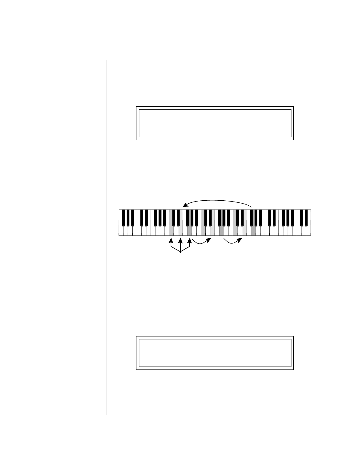
Arp/Beats Menu
Master Arpeggiator Parameters
Extension Count The Extension Count parameter specifies how many times the Extension
Interval is carried out. With an Extension Count of 0, the arpeggio plays
only the notes pressed. With an Extension Count of 1, the arpeggio plays
the notes pressed, then plays the same notes (in the same order), transposed by the Extension Interval amount. The cycle is then repeated.
MASTER ARPEGGIATOR
Extension Count 4
For example, with the Extension Interval set to 12 (an octave) and an
Extension Count of 2, and with the Arpeggiator Mode set to Fwd Assign, if
you played E2, then C2, then G2, the arpeggiated sequence would consist
of: E2, C2, G2, then E3, C3, G3, and then E4, C4, G4. The Extension Count
values range from 0 through 15. Refer to the following illustration.
Back
123 456 789
Extend 1
Played
Extend 2
Extension Interval The Extension Interval specifies the additional intervals played when you
press a key. For example, suppose you played C2 with an Interval of 7 (a
Major 5th), Up mode, and an Extension Count of 2. The arpeggio alternates
between C2 and G2.
The Extension Interval values range from 1 through 16.
MASTER ARPEGGIATOR
Extension Interval 7
62 E-MU Systems
Page 73

Arp/Beats Menu
Master Arpeggiator Parameters
Sync The Sync parameter defines when a note is played in relation to when the
key is pressed. When set to “Key Sync”, the note sounds the instant a key is
pressed. When set to “Quantized”, the note does not sound until the next
occurrence of the selected note value.
MASTER ARPEGGIATOR
Sync key sync
The following diagram illustrates how Key Sync and Quantize work.
Key
Pressed
Note Sounds
Immediately
Key Sync
Quarter Notes
Note Doesn't Sound until
the Next Quarter Note
Quantize
Quarter Notes
Pre-Delay The Pre-Delay value determines how long the arpeggiator is delayed before
becoming active after the first “note-on.” During the pre-delay period,
notes are played normally (as if the arpeggiator was off). After the pre-delay
period has elapsed, the arpeggiator kicks in. Once you release all the keys
on the controller, the pre-delay starts over with the next note-on. In combination with the Duration parameter, Pre-Delay lets you create many more
variations in the arpeggio patterns. Please refer to the diagram on page 65.
You can play the preset normally as long as you don’t hold the notes longer
than the Pre-Delay. If you do, the arpeggiator starts in. When used in
conjunction with multiple arpeggiators, Pre-Delay allows you to offset the
time between the different patterns.
MASTER ARPEGGIATOR
Pre-Delay off
XK-6 Owners Manual 63
Page 74

Arp/Beats Menu
Master Arpeggiator Parameters
Duration This parameter defines how long the arpeggiator plays before stopping. The
Duration is specified in note values. Therefore if an arpeggio were running
at a 16th Note Value and the Duration were set to a whole note, the arpeg-
giator would play 16 steps before stopping. After the duration has elapsed,
the arpeggiator remains inactive until the key is released. If Duration is set
to Off, the arpeggio repeats as long as the notes are held (Infinite Duration).
MASTER ARPEGGIATOR
Duration 1 / 1d
Duration can be used to modify the patterns and increase the possible
pattern combinations and variations. Because this parameter limits the
length of arpeggiator play time, it can change the arpeggio pattern when
the Duration is less than the length of the arpeggio. You can set the
arpeggio to repeat continuously using the Recycle function described below.
Post-Delay This parameter is only relevant when both the “Duration” and “Recycle”
parameters are not in the “Off” state. The Post-Delay value determines how
long the arpeggiator is delayed after the Duration period. Please refer to the
diagram on page 65. During the post-delay period, notes are played normally
(as if the arpeggiator was off). After the post-delay period has elapsed, the
arpeggiator either jumps to the beginning of the Pre-Delay period or to the
beginning of the Duration period depending on the Recycle setting.
If the arpeggiator is playing an extension when the Duration expires, the
notes in the extension will continue to sound during the Post-Delay (and
Pre-Delay if on). On the next pass through the Duration period, the
extension continues where it left off.
Post-Delay increases the number of possible variations in the beat and
allows the recycle loop to be set to an exact measure of time.
MASTER ARPEGGIATOR
Post-Delay off
64 E-MU Systems
Page 75

Arp/Beats Menu
Master Arpeggiator Parameters
Keys
Pressed
Arp PlaysNotes Sound Notes Sound
Pre-Delay Duration Post-Delay
R
R
e
c
y
c
l
e
o
e
c
y
c
l
e
o
-
o
N
/
n
n
y
l
D
e
r
P
Recycle Recycle enables the pattern or arpeggio to repeat. This parameter works
together with the Duration and Pre/Post Delay parameters to allow the loop
to be set to an exact measure of time. The “on/No-PreDelay” option
bypasses the predelay period. With Recycle turned Off, the pattern or
arpeggio stops at the end of the Post-Delay period.
MASTER ARPEGGIATOR
Recycle on/No-PreDly
Keyboard Thru When enabled, Keyboard Thru merges the notes not arpeggiated with the
notes being produced by the arpeggiator. This gives the effect of two parts
playing at once.
MASTER ARPEGGIATOR
Keyboard Thru off
Latch With Latch mode On, any notes you play remain on until you press them
again. Latched notes can also be halted by turning Latch off in this screen,
or by turning off the Arpeggiator for the channel in the main screen.
MASTER ARPEGGIATOR
Latch on
XK-6 Owners Manual 65
Page 76

Arp/Beats Menu
Send MIDI System Exclusive Data
Use the Key Range parameter to set the keyboard range for the arpeggiator.
Notes inside the range will arpeggiate while notes outside the specified
range will not arpeggiate. Use the Extensions parameters to exceed the
upper boundary of the Key Range (see the information about Extensions
beginning on page 62).
MASTER ARPEGGIATOR
Key Range C-2->G8
Move the cursor under the first key and use the data entry control to define
the lowest key to be arpeggiated. Move the cursor under the second key
value and use the data entry control to define the highest key to be arpeggiated.
Send MIDI System Exclusive Data
Send data as you would
a regular sequence. Sending
data in one huge chunk may
clog the MIDI input buffer on
XK-6.
Transmits the Arpeggiator Patterns via the MIDI out port as MIDI System
Exclusive data to another XK-6 or to a computer/sequencer for backup.
Using the cursor key and the data entry control, select the MIDI data you
want to transmit. See Send MIDI System Exclusive Data in the Master chapter
for additional details about recording SysEx.
User Patterns
Transmits all the User patterns.
000 to 99
Transmits only the individual pattern you have selected.
0
SEND MIDI SYSEX DATA
All User Arp Patterns
66 E-MU Systems
Page 77

Arp/Beats Menu
Send MIDI System Exclusive Data
Editing a User Arpeggiator Pattern
Bank 0 = User Patterns
Bank 1 = Factory Patterns
Bank 2 = Factory Patterns
OO
OO
Before editing a Pattern,
select Master Arpeggiator (M) in
the main screen and set the
Arpeggiator to the Pattern you
are editing. This lets you hear
the Pattern as you edit it.
XK-6 lets you create and edit your own arpeggiator patterns. Using the Edit
User Pattern menu, you can create up to 100 user patterns and each pattern
can be up to 32 steps in length.
When you edit a pattern, you are writing directly into memory—no Save
command is required (however, you must exit the Arp module). This is
different from the Edit menu where you must Save a preset before it will be
overwritten. If you want to modify an existing pattern and keep the
original, you must first COPY the pattern you want to edit to another
location using the function in the Save/Copy menu (See page 191). Refer to
the instructions below and the following parameter descriptions to create
your own patterns.
EDIT USER PATTERN
1
01
DRUMnBASS 1
To Select the Pattern to Edit:
1. From the Edit User Pattern screen shown above, move the cursor to the
bottom line and select the pattern you want to edit. The Enter LED
begins flashing. Press Enter to move back to the Home position.
2. Select the next screen in the list, “User Pattern Edit”. This is where you
edit the currently selected pattern.
PTRN KEY VEL DUR RPT
S01 +0 ply 1/8 2
Pattern Step
number
3. Move the cursor to the lower line of the display. For each step, you can
select: key, velocity, duration, and number of repeats.
Key offset Velocity Duration Repeat
Pattern Step Number You can set up to 32 steps for each arpeggiator pattern. This field selects
which step you will be editing from 1 to 32.
Key This parameter defines what happens during the current step. The Key
parameter can do one of five different operations. Following is a description
of each of the key functions and how to use them.
XK-6 Owners Manual 67
Page 78

Arp/Beats Menu
Send MIDI System Exclusive Data
Key Offset
This parameter defines not the actual note of the arpeggiator playback, but
instead specifies the amount of offset, in semitones, from the original note
played. You can set a Key Offset from -48 to +48 for each step. For example,
if you play a “C” on the keyboard with the Key Offset amount for the first
step set to “+1,” the first step in the pattern will be “C#.”
+12-12 0 +24-24 +36-36-48 +48
__
__
IMPORTANT: The Gate
function in the arpeggiator
MUST be set to 100% when
using the tie function, otherwise
the tied note is retriggered
instead of extended.
Played
Note
Tie
This function extends the duration of notes beyond the values given in the
duration field by “tying” notes together. You can tie together any number
of consecutive steps.
+2
Step 1
Rest
Instead of playing a note, you can define the step as a Rest. The Duration
parameter specifies the length of the rest. Rests can be tied together to form
longer rests.
tie
Step 2
+ OffsetOffset
-5
Step 3
68 E-MU Systems
Skip
This command simply removes the step from the pattern. The Skip feature
makes it easy to remove an unwanted step without rearranging the entire
pattern. You’ll be happy to know that the velocity, duration and repeat
parameters are remembered if you decide to put the step back later.
End
This command signals the end of the pattern. Any steps programmed after
the step containing the End command are ignored.
Page 79

Arp/Beats Menu
Send MIDI System Exclusive Data
Velocity Each note in the pattern plays using either a preset velocity value (from
1 through 127), or using the actual velocity of the played note (ply).
Note: Velocity values will not have an effect on the sound unless velocity is
programmed to do something in the preset.
Duration This parameter sets the length of time for the current step, defined as a note
value, based on the Master Tempo. The selectable note durations are
described below.
1/32 32nd Note
1/16t 16th Note Triplet
1/32d Dotted 32nd Note
1/16 16th Note
1/8t 8th Note Triplet
1/16d Dotted 16th Note
1/8 8th Note
1/4t Quarter Note Triplet
1/8d Dotted Eighth Note
1/4 Quarter Note
1/2t Half Note Triplet
1/4d Dotted Quarter Note
1/2 Half Note
1/1d Dotted Whole Note
1/1t Whole Note Triplet
1/2d Dotted Half Note
1/1 Whole Note
2/1t Double Whole Note
Triplet
2/1 Double Whole Note
Repeat Each step can be played from 1 to 32 times. A repeat setting of “1” indicates
the step will be played one time (not repeated one time or played twice).
To Edit a User Pattern:
1. The first field in the Edit User Pattern field defines the pattern’s step
number. Start with the pattern Step 01.
2. Define the Key Offset, Velocity, Duration and Repeat values.
3. Repeat steps 1 and 2 until you have setup the desired number of steps
in the pattern.
4. Set the Key Offset to “End” on the last step in the pattern.
XK-6 Owners Manual 69
Page 80
Arp/Beats Menu
Multichannel Arpeggiating
User Pattern Name The User Pattern Name page lets you enter a name for any User Arpeggiator
Pattern.
PTRN KEY VEL DUR RPT
S01 +0 ply 1/8 2
To Name a User Pattern:
1. From the Pattern Edit screen shown above, position the cursor under
the PTRN field.
2. Turn the data entry control clockwise. The following screen appears.
USER PATTERN NAME
0
00
Mod Cycle
Multichannel Arpeggiating
3. Move the cursor to the bottom line and edit the Pattern name using
the data entry control and Cursor keys.
4. Move the cursor to the “Home” position (shown above) by pressing the
Home/Enter button.
5. Turn the data entry control counter-clockwise one click to return to
the Pattern Edit screen.
6. Turn the data entry control counterclockwise multiple clicks to jump
back to the main Arpeggiator menu screen.
Presets with the arpeggiator assigned will play when they receive note-on
data from the keyboard or external MIDI source.
Please refer to the instructions on page 26 to learn one way to perform
using multiple arpeggiators.
70 E-MU Systems
Page 81

Controllers Menu
The Controllers menu contains functions related to the keyboard, knobs or
trigger buttons of XK-6. For example, the Command Function Trigger Keys
are programmed in this menu. All Controllers menu data is saved with the
Multisetup. See page 41 for more information about Multisetups.
To enable the Controllers menu:
Press the Controllers button, lighting the LED. The Controllers Menu
screen displays the menu page most recently selected since powering up
XK-6. The cursor appears below the first character of the screen heading on
line one.
To select a new screen:
Press the Home/Enter button or press the Cursor button repeatedly until
the cursor is below the screen title heading. Rotate the data entry control to
select another screen.
To modify a parameter:
Press either Cursor button repeatedly (or hold down the right cursor button
while turning the data entry control) until the cursor is below the desired
parameter value. Rotate the data entry control to change the value.
To return to the previously selected Mode/View screen:
Press the Controllers button, turning off the LED.
XK-6 Owners Manual 71
Page 82

Controllers Menu
Keyboard Channel
Realtime
Control
This section describes how set up the Realtime Controllers on XK-6.
Realtime Controllers are performance controls such as the controller knobs,
velocity & pressure sensitive keyboard, and the trigger buttons.
Functions
Keyboard Channel This option allows you to select which channel is controlled by the
Keyboard, Knobs as well as the Pitch & Mod Wheels. You can select any of
the 16 channels or “Basic”. If the “Basic” channel is selected, the keyboard
and knobs always control the preset showing in the Main screen.
in Quick Edit mode the
front panel knobs only control
the “Basic Channel”.
Keyboard Transpose This option allows you to offset the transposition of the keyboard in
semitone intervals. This is allows you to easily play in different keys with
the keyboard and lets you access different groups of instruments in a drum
map. The transpose range is ±36 semitones.
KEYBOARD CHANNEL
Channel: Basic
KEYBOARD TRANSPOSE
+00 semitones
Local Control On/Off Local Control is used to disconnect the keyboard and controllers (knobs,
wheels, footswitches) from the sound generating section. Even though
disconnected from the internal synthesizer, the keyboard and controllers
are still transmitted over MIDI. Local Control is normally turned Off when
recording into an external MIDI sequencer (set sequencer to Echo Thru).
Played data and recorded data are merged in the computer sequencer and
then sent back to the module. This feature can also be used if you want to
control another MIDI sound generator from the keyboard and knobs
without playing internal sounds.
LOCAL CONTROL ON/OFF
on
72 E-MU Systems
Page 83
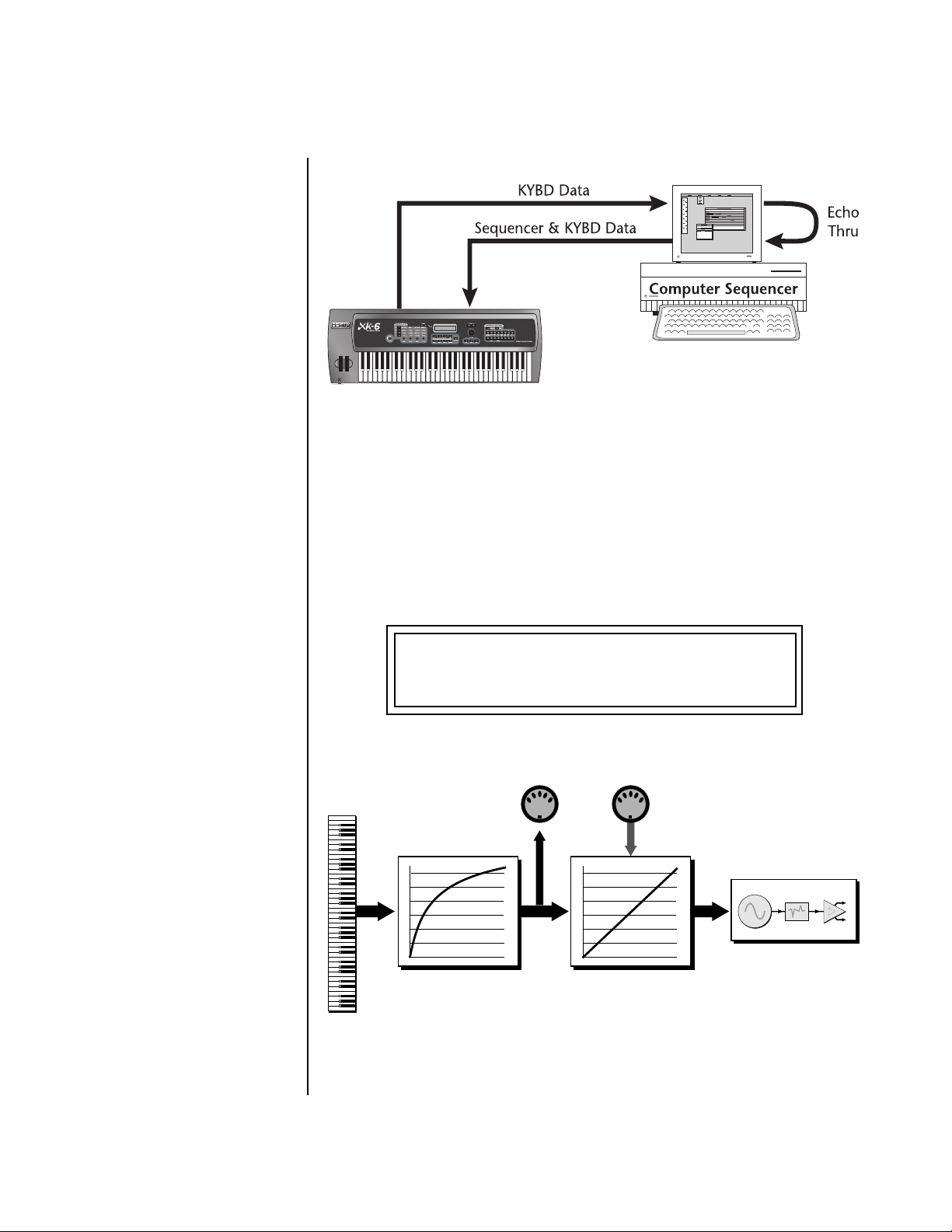
Controllers Menu
Keyboard Velocity Curve
Keyboard Velocity
Curve
MIDI
Out
CO1A V ol 127 Pan00RSUER
2
032
bas:Int er fer ence
MIDI
In
Turning Local Control Off allows you to use the Echo Thru feature on your sequencer
while sequencing. In conjunction with Echo Thru, Local Control Off allows you to record
into the external sequencer and hear the correct sounds whether you are recording or
playing back the sequence.
The velocity response of the keyboard can be adjusted using any of 17
curves in order to customize the dynamic feel of the keyboard to your
individual playing style. This curve adjusts the output of the XK-6
keyboard before it is sent to the MIDI output port and to the Master
Velocity Curve described on page 85.
KEYBOARD VELOCITY CURVE
soft #2
The Keyboard Velocity
Curve diagrams are located on
page 232.
MIDI OUT MIDI IN
Instrument
Z-Plane
Filter
L
Amp
R
Internal
Keyboard
Velocity Curve
Master
Velocity Curve
The Keyboard Velocity Curve modifies the velocity data from the keyboard keys. This data
is sent to the MIDI output port and through the Master Velocity Curve before reaching
the Synthesizer. Incoming MIDI data is filtered through the Master Velocity Curve only.
Synthesizer
XK-6 Owners Manual 73
Page 84
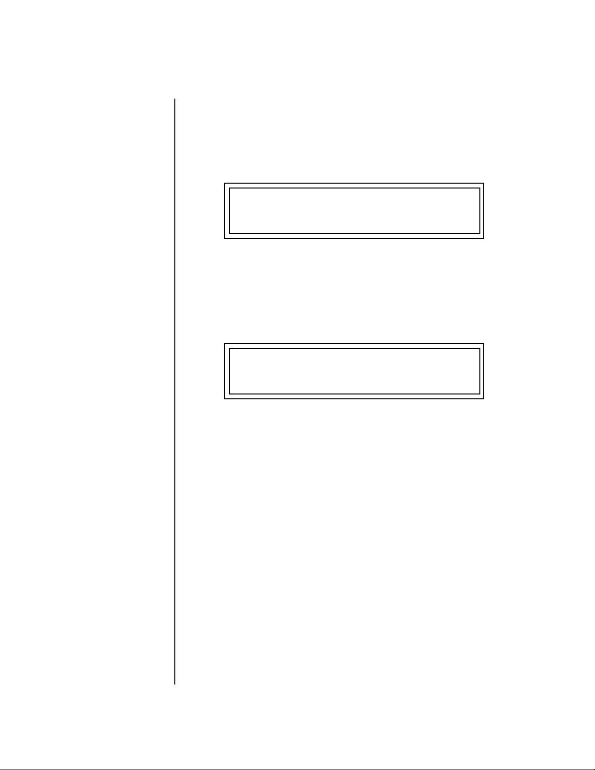
Controllers Menu
Channel Aftertouch On/Off
Channel Aftertouch
On/Off
The keyboard generates channel aftertouch messages. Aftertouch is
generated when you continue to press the keys after the note has been
played. Aftertouch can be a very useful controller for adding a bit of vibrato
or creating a volume swell. Aftertouch is routed to the Pressure source in
the PatchCord screen. This control allows you to turn aftertouch on or off
without having to modify each preset.
CHANNEL AFTERTOUCH
on
Footswitch Function The footswitch jack on XK-6’s rear panel can be programmed to perform a
variety of functions. The footswitch jack is designed to accept a momentary
footswitches which shorts the tip and ground. XK-6 senses either normallyon or normally-off switches on power-up.
The following functions can be controlled via the footswitches.
FOOTSWITCH JACK FUNCTION
MIDI FtSw
• MIDI Footswitch In this mode the footswitch is routed to the
“FootSw1” PatchCord source in the Preset Edit,
Cords menu. (See pages 159 and 166.) It is also transmitted out on the Footswitch Controller number as
programmed in the Controllers menu. (See page 80.)
• Tap Tempo Pressing the footswitch allows you to tap in the
current tempo with your foot.
• Channel + Pressing the footswitch increments the MIDI
channel number.
• Channel - Pressing the footswitch decrements the MIDI
channel number.
• Preset + Pressing the footswitch increments the current
preset number.
• Preset - Pressing the footswitch decrements the current
preset number.
74 E-MU Systems
Page 85
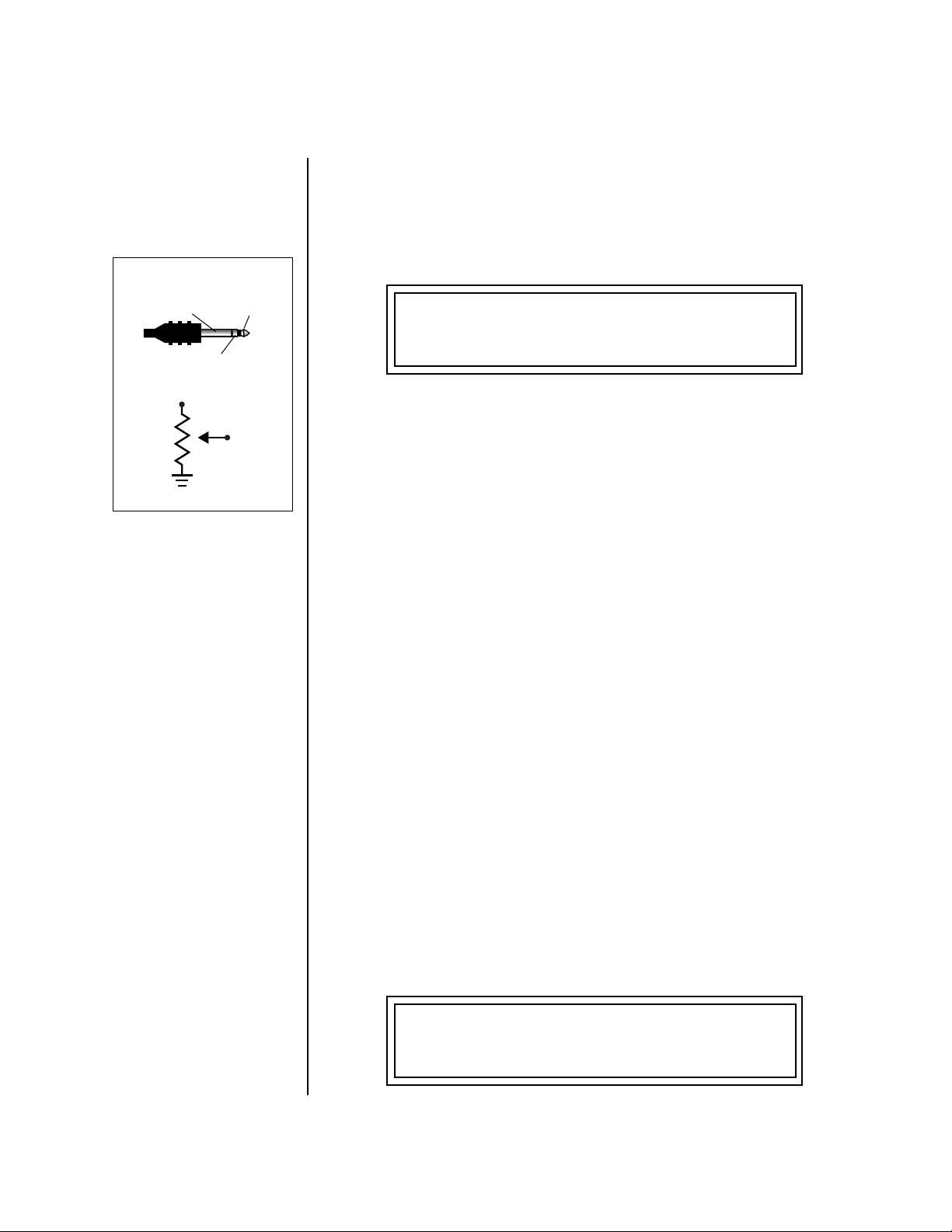
Controllers Menu
Foot Pedal Function
Foot Pedal Function The foot pedal jack on XK-6’s rear panel can be programmed to perform a
variety of functions. The foot pedal input can sense either 0-5 volts on the
ring of a stereo jack or a foot pedal with the potentiometer wired as shown
at left.
The following functions can be controlled via the foot pedal jack.
Pedal Wiring
Ground Tip
Ring
Tip
Ring
Ground
Trigger Buttons Function
FOOT PEDAL FUNCTION
FootCtrl
• Foot Controller In this mode the Foot Pedal is routed to the
“Pedal” PatchCord source in the Preset Edit, Cords
menu. (See pages 159 and 166.) It is also transmitted
out on MIDI Continuous Controller #4 on the basic
MIDI channel.
• Channel Volume The Foot Pedal controls the volume of the current
channel. (The MIDI channel currently showing in
the main screen.) Channel volume is pre-effect—
reverb or echoes will continue to sound even when
the pedal is off.
• Master Volume The Foot Pedal controls the overall volume of the
XK-6. This duplicates the function of the Master
Volume knob on the front panel. Master volume is
post-effect—effects will be cut off when the pedal is
off.
This option selects the function of the front panel “Triggers” button. The
“Triggers” button can be used either to Play Beats Parts or to Play Note
Events.
• Play Beats Parts In this mode and when the Triggers button is
selected, the sixteen command buttons turn Beats
parts on and off.
• Play Note Events In this mode and when the Triggers button is
selected, the sixteen command buttons work like
keyboard notes. Each button can be assigned to any
MIDI note, on any MIDI Channel (01-16), with any
velocity (0-127), and can be set to be latched or
momentarily on.
TRIGGER BUTTONS FUNCTION
Play Note Events
XK-6 Owners Manual 75
Page 86
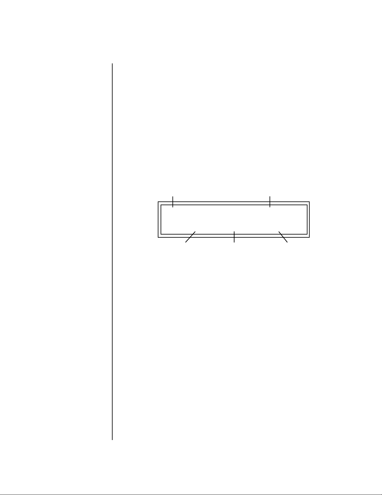
Controllers Menu
Trigger Buttons
Trigger Buttons This screen allows you to program the 16 trigger buttons to play note
events. Note: This screen is not available when the “Trigger Buttons
Function” (see previous page) is set to “Play Beats Parts”.
Set the previous screen to “Play Note Events”. Select Triggers mode by
pressing the mode select button so that the “Triggers” LED is illuminated.
Now the 16 buttons work like keyboard notes. Each of the 16 buttons can
be assigned to any MIDI note, on any MIDI Channel (01-16), with any
velocity (0-127), and can be set to be latched or momentarily on. Latched
notes will hold until the button is pressed again. Latched notes will be
indicated by the LEDs.
OO
By assigning Trigger
OO
Buttons to the keyboard Beats
Layout Keys (page 51), you can
trigger Beats and MIDI notes
using the Trigger buttons.
Simply move the cursor from the “TRIGGERS” field and play a note to enter
the MIDI key and velocity. Pressing a Trigger Button anytime while in this
screen automatically selects that trigger button for programming!
Trigger Button Select Latch on/off
OO
OO
Latched buttons are
especially useful for triggering
arpeggiated presets.
T1 TRIGGERS Latch:off
Key: C3 Ch: 01 Vel: 127
MIDI Key MIDI Channel
To Setup the Trigger Buttons:
1. Press the Controllers button. Its LED will illuminate.
2. Turn the data entry control to select the “TRIGGERS” screen.
3. Use the left/right cursor controls to select the fields shown above.
4. Select the MIDI key, the MIDI channel, the Velocity and Latch on/off
for each of the 16 trigger buttons.
5. Save the Multisetup if you want to save these settings. See page 42.
To Play the Trigger Buttons:
1. Press the Controllers button. Its LED will illuminate.
2. Turn the data entry control to select the “TRIGGERS BUTTONS
FUNCTION” screen.
3. Move the cursor to the lower line and select “Play Note Events”.
4. Press the Command Functions “Triggers” button so that its LED
illuminates.
5. Play the Trigger buttons.
Velocity
76 E-MU Systems
Page 87

Controllers Menu
Preset Select Buttons
Preset Select Buttons The 16 command buttons can also be used for preset selection. Each button
can be programmed to select any preset on the Basic MIDI channel. For
your next song, selecting another Multisetup (page 41) selects another
group of sixteen presets.
In Preset Select mode, whenever the current preset on the basic channel
matches any of the 16 “favorites” assigned to the Preset Select buttons, its
LED will illuminate.
The Basic MIDI channel
is the channel currently showing
in the main screen.
Select Preset Select mode from the Command Functions. Now the 16
buttons are programmable preset selection buttons.
Trigger Button Select Preset Location
T1 PRESET - SELECT User
0
006
bas: Fatty
Preset Number Preset Name
When a preset is selected using the Preset Select buttons, the cursor is
automatically located underneath the Preset Name field. This feature
makes it easy to select other presets of the same type.
Quick Method of Programming the Preset Select Buttons:
1. Select the preset you want from the Main screen.
2. Press and hold the Preset Select button, then press one of the sixteen
Trigger buttons.
3. The preset will be stored in the trigger button you selected.
To Program the Preset Select Buttons from the Menu:
1. Press the Controllers button. Its LED will illuminate.
2. Turn the data entry control to select the “PRESET - SELECT” screen.
3. Use the left/right cursor controls to select the fields shown above.
4. Select the desired preset for each of the 16 trigger buttons.
5. Save the Multisetup if you want to save these settings. See page 42.
To Use the Preset Select Buttons:
1. From the main preset selection screen, press the Preset Select button.
Its LED will illuminate.
2. Press any of the 16 buttons to select a new preset.
Category
XK-6 Owners Manual 77
Page 88

Controllers Menu
Preset Select Send Buttons
Preset Select Send
Buttons
Suppose you wanted to send another MIDI program change message to an
external synthesizer. The 16 command buttons can also send external MIDI
program changes on the Basic MIDI channel. Each button can be
programmed to select any preset from 0-127, in any bank.
Select Preset Select mode from the Command Functions. Now the 16
buttons are programmable preset selection buttons.
Trigger Button Select
T1 PRESET - SELECT SEND
MSB:015 LSB:003 PROG: 127
Bank MSB Program Change
Bank LSB
Number
To Program the Program Change Send Buttons:
1. Press the Controllers button. Its LED will illuminate.
2. Turn the data entry control to select the “PRESET - SELECT SEND”
screen.
3. Use the left/right cursor controls to select the fields shown above.
4. Select the desired program change and bank for each of the 16 trigger
buttons. (If you don’t want to send an external program change, set the
fields to “off”.)
5. Save the Multisetup if you want to save these settings. See page 42.
78 E-MU Systems
To Send an External Program Change:
1. From the main preset selection screen, press the Preset Select button.
Its LED will illuminate.
2. Press one of the 16 buttons to send the program change.
Page 89

Controllers Menu
Knob Preset Quick-Edit
Knob Preset
Quick-Edit
Real-time Controller Assignment
OO
OO
Tip: XK-6 factory presets
have certain synth parameters
assigned to each controller letter
and so these are “Global”
controller assignments.
“Quick-Edit” changes the initial controller setting in the preset whenever
you move a Control Knob. This parameter selects whether or not the front
panel Controller Knobs are used to Quick-Edit the currently selected preset.
See “Preset Edit Button” on page 32 in the Operations chapter for more
details.
KNOBS PRESET QUICK-EDIT
disabled
Use these three pages to assign sixteen real-time control sources. Each MIDI
Controller is assigned a letter (A - P). The front panel Controller Knobs and
sixteen MIDI controller numbers share the A-P controller routings. These
screens let you select which MIDI real-time controllers numbers will be
received (from 1 to 31 and from 64 to 95) and which controller numbers
will be transmitted over MIDI if the front panel controls are turned.
The PatchCord routing and amount in the Preset Edit menu determine
what effect the controller has on each preset. Real-time controllers are
shown in the PatchCord menu as MIDI A through MIDI P.
The Real-time Controller assignment also specifies which controller
numbers are transmitted when the “Knobs Output MIDI” is enabled (see
“Knobs Output MIDI” on page 94).
REALTIME CONTROLLER #
A: 74 B: 71 C: 25 D: 26
For example, assigning a MIDI
controller to “A” in this screen
would let you control filter Fc for
all the factory presets. See
“Front Panel Knob Functions” on
page 209.
REALTIME CONTROLLER #
E: 73 F: 75 G: 85 H: 72
REALTIME CONTROLLER #
I: 78 J: 77 K: 27 L: 28
REALTIME CONTROLLER #
M: 01 N: 03 O: 82 P: 83
XK-6 Owners Manual 79
Page 90

Controllers Menu
2
4
5
MIDI Footswitch Assign
Note: Controllers 7 and 10 are already assigned to Volume and Pan for each
MIDI channel. Controllers 91 & 93 are the standard controller numbers for
reverb and chorus send amounts, but are not assigned.
Following are a few of the standardized MIDI Controller numbers as
defined by the MIDI manufacturers association. The controllers shown in
Bold are automatically routed to the destination (volume & pan) or have
their own PatchCord source. Others, such as Portamento Time, can be
routed using a PatchCord to have the desired effect.
MIDI Footswitch Assign
1 - Modulation Wheel
- Breath Controller
- Foot Pedal
- Portamento Time
6 - Data Entry
Like the MIDI Controllers, you can assign three MIDI footswitches to MIDI
footswitch numbers. Footswitches numbers are from 64-79. Destinations
for the footswitch controllers are programmed in the PatchCord section of
the Preset Edit menu. The rear panel footswitch 1 is connected to
footswitch controller 1 in this screen. Pressing the footswitch transmits on
the MIDI controller number programmed here. Footswitches 2 & 3 route
incoming MIDI footswitch data to the PatchCord section of XK-6.
7 - Volume
8 - Balance
9 - Undefined
10 - Pan
11 - Expression
FOOTSWITCH CONTROLLER #
1: 64 2: 65 3: 66
Rear panel footswitch input
Calibrate Controllers This screen allows you to calibrate the Pitch Wheel, Modulation Wheel,
Aftertouch, and Foot Pedal controller. The controls should be recalibrated
periodically in order to compensate for normal changes in the controls
themselves. If a control doesn’t seem to be responding properly, it may
simply need to be recalibrated.
The Controllers should
ALWAYS be calibrated after you
reinitialize user data. (And you
should always reinitialize user
data after updating the
operating system.)
80 E-MU Systems
CALIBRATE CONTROLLERS
Start Mod Wheel
Page 91

Controllers Menu
Tempo Controller
To Calibrate the Controllers:
1. Press the Global button. Its LED will illuminate.
2. Turn the data entry control to select the “CALIBRATE CONTROLLERS”
screen shown below.
CALIBRATE CONTROLLERS
Start Mod Wheel
3. Move the cursor to the lower line of the display and rotate the Data
Entry Control to select the control to be calibrated. The choices are:
• Mod Wheel • Pitch Wheel • Foot Pedal • Aftertouch
4. Press Enter to select a control, then follow the instructions given in the
display. You will be asked to mover the control through its entire range
(minimum through maximum), then press Enter.
5. In the case of the Pitch Wheel, you first move the wheel through its
min-max range and leave the wheel resting in its center position. Then
press Enter.
Tempo Controller This function allows a MIDI controller to change the Base Tempo of the
Master Clock. The Master Clock is used by the arpeggiators, clock divisor
PatchCords, tempo-based envelopes and synced LFOs. (See “Clock
Modulation” on page 106.) You can assign any controller number from 031, mono key pressure, or the Pitch Wheel to change the Global Tempo.
A different controller can be used to change the tempo up or down. The
Pitch Wheel can be assigned to both the up and down parameters to vary
the tempo up and down from a single controller. If any other controller is
assigned to both the up and down parameters, XK-6 redefines the center of
the controller’s range as zero (so it acts like a pitch wheel).
MIDI Controller values are added to the Base Tempo with a range of ±64.
When the controller is set to “off” the tempo returns to its original setting.
Controllers are only recognized on the selected MIDI channel, unless XK-6
is in Omni mode, in which case all channels are accepted. This control has
no effect when using an external clock.
TEMPO CONTROLLER# CHAN
Up: 03 Down: 09 16
XK-6 Owners Manual 81
Page 92

Controllers Menu
Base Tempo
Base Tempo XK-6 contains an internal Master Clock which runs the arpeggiators,
synchronizes the LFOs when in tempo-based mode, controls the times of
tempo-based envelopes, and can be used as a modulation source in the
PatchCords section.
You’ll notice that there are two tempo values shown in the display.
• Base Tempo - This is the base tempo setting before being modified by
the Tempo Controller (if engaged). See “Tempo Controller” on page 81.
The Arp/Beats LED
flashes in time with the Base
Tempo.
• (Current Tempo) - This is the actual tempo! The current tempo is
equal to the base tempo modulated by the MIDI controller specified in
the Tempo Controller screen. If no MIDI Tempo controller message has
been received since the last Base Tempo change, the Current Tempo will
be equal to the Base Tempo.
To Change the Base Tempo:
1. Move the cursor to the lower line of the display.
2. Adjust the Base Tempo using the data entry control.
OO
OO
You can also tap tempo
using a footswitch. See page 74.
BASE TEMPO TAP->enter
120 bpm (current: 182)
3. To Tap Tempo - Tap the Enter button at least three times. Keep tapping
to continuously update the tempo on each tap. The tap tempo range is
25-300 bpm. The Base Tempo values range from 1 through 300 beats
per minute (BPM).
To Use an External MIDI Clock:
1. Move the cursor to the lower line of the display.
2. Turn the data entry control all the way counter-clockwise and select
“ext” to use an external MIDI clock source.
82 E-MU Systems
Page 93

Global Menu
The Global menu contains functions that affect the overall operation of
XK-6. For example, changing the Master Tune parameter changes the
tuning of all the presets, not just the one currently displayed.
To enable the Global menu:
Press the Global button, lighting the LED. The Global Menu screen displays
the menu page most recently selected since powering up XK-6. The cursor
appears below the first character of the screen heading on line one.
__
__
Warning: Global Menu
changes are automatically saved
when you exit the menu. If the
power is turned off before you
exit the menu any changes you
have made will be lost.
To select a new screen:
Press the Home/Enter button or press the Cursor button repeatedly until
the cursor is below the screen title heading. Rotate the data entry control to
select another screen.
To modify a parameter:
Press either Cursor button repeatedly (or hold down the right cursor button
while turning the data entry control) until the cursor is below the desired
parameter value. Rotate the data entry control to change the value.
To return to the previously selected screen:
Press the Global button, turning off the LED.
XK-6 Owners Manual 83
Page 94

Global Menu
Defining Global Parameters
Defining
Global
Global setup parameters affect overall performance, range, and global
effects. This section describes the Global parameters and how to define
them.
Parameters
Master Transpose/ Tune
Master Bend Range The Master Bend Range parameter sets the range of the pitch wheel. This
The Transpose parameter transposes the key of all presets, in semitone
intervals. The transpose range is ± 24 semitones.
Master Tune adjusts the fine tuning of all presets so that you can tune XK-6
to other instruments. The master tuning range is ± 1 semitone in 1/64th
semitone increments (1.56 cents). A master tune setting of “+00” indicates
that XK-6 is perfectly tuned to concert pitch (A=440 Hz).
MASTER TRANSPOSE TUNE
+00 semitones +00
affects only presets that have their individual Pitch Bend range (defined in
the Preset Edit menu) set to Master. See page 160. The maximum pitch bend
range is ±12 semitones or one octave in each direction.
84 E-MU Systems
MASTER BEND RANGE
+/- 7 semitones
Page 95

Global Menu
Defining Global Parameters
Master Velocity Curve
The Master Velocity curve
is normally set to “Linear” and
the Keyboard Velocity Curve is
used to adjust the keyboard feel.
The two curves can also be
combined if you wish.
Incoming velocity data or internal keyboard velocity can be altered by one
of thirteen velocity curves. These curves are designed to adapt XK-6 to a
external MIDI controller. You can select one of thirteen global velocity
curves or to leave the data unaltered (linear). To adjust Keyboard velocity,
see “Keyboard Velocity Curve” on page 73.
MASTER VELOCITY CURVE
13
Keyboard
Velocity Curve
MIDI OUT MIDI IN
Master
Velocity Curve
The Master Velocity
Curve filters MIDI In as
well as data from the
Keyboard Velocity Curve.
Z-Plane
Instrument
Amp
Filter
Internal
Synthesizer
L
R
For a complete list of
all available velocity curves,
see “Master Velocity Curves”
on page 233 of the Appendix.
120
100
Result Velocity
Linear
80
60
40
20
0
20
0
40
Played Velocity
120
100
Curve 9
80
60
40
20
Result Velocity
0
20
0
40
Played Velocity
120
100
Curve 2
80
60
40
20
Result Velocity
0
20
0
40
100
120
80
60
60
120
100
80
Played Velocity
120
100
80
60
40
20
Result Velocity
0
20
120
100
80
60
0
Curve 13
40
100
120
80
60
Played Velocity
XK-6 Owners Manual 85
Page 96
Global Menu
Defining Global Parameters
Mix Output The Mix Output parameter allows you to override the routing assignments
made in each preset and instead assign the outputs according to MIDI
channel. For each of the 16 MIDI channels, you can select Send 1-4, or
Preset. When Preset is selected, the output assignment defined in the Preset
Edit menu is used.
MIX OUTPUT
channel 16: Send 1->main
Indicates that the dry signal is
routed to the Main output jacks.
The Output Routing field (pointed to by the arrow) reflects the true
routing of Send 2 or Send 3 to either:
1) the effects processor input or… 2) the rear panel submix jacks.
Since the Sub 1 output is NOT being used, the signal is routed through the
effects processors, then on to the main outputs. If a plug were inserted into
one of the Sub 1 jacks the destination field would read “Sub1” for Send 2
and the dry signal would be routed directly to the Sub 1 outputs on the
back panel.
Send Routings
Send 1 - Main Outputs
Send 2 - Subout 1 or Main Outs
Send 3 - Main Outs
Send 4 - Main Outputs
MIX OUTPUT
channel 15: use preset
The Sends function as effect processor inputs (effect sends). Send 2 is also
used to route sounds to the Sub 1 outputs on the back panel. When a plug
is inserted into the associated Submix jack on the back panel, the Dry
portion of the Send is disconnected from the effects processor and the
signal is routed directly to the output jack. The Arrow points to the actual
output routing. If you don’t want the wet portion of the signal in the main
mix, turn down the Send Level. The entire Send is disconnected from the Effects
Processors even if only one plug is inserted into the Submix jack.
The four Effect Sends allow you to get the most out of the two effect
processors. For example, with Effect B set to an echo algorithm, you could
route one MIDI channel to Send 3 and set the effect amount to 80%.
Another MIDI channel could be routed to Send 4 with an effect amount of
only 5%. This is almost like having two different effects!
The Mix Output function is also useful when sequencing since it lets you
route specific MIDI channels to specific Sub outputs (on the back panel)
where there they can be processed with EQ or other outboard effects.
86 E-MU Systems
Page 97
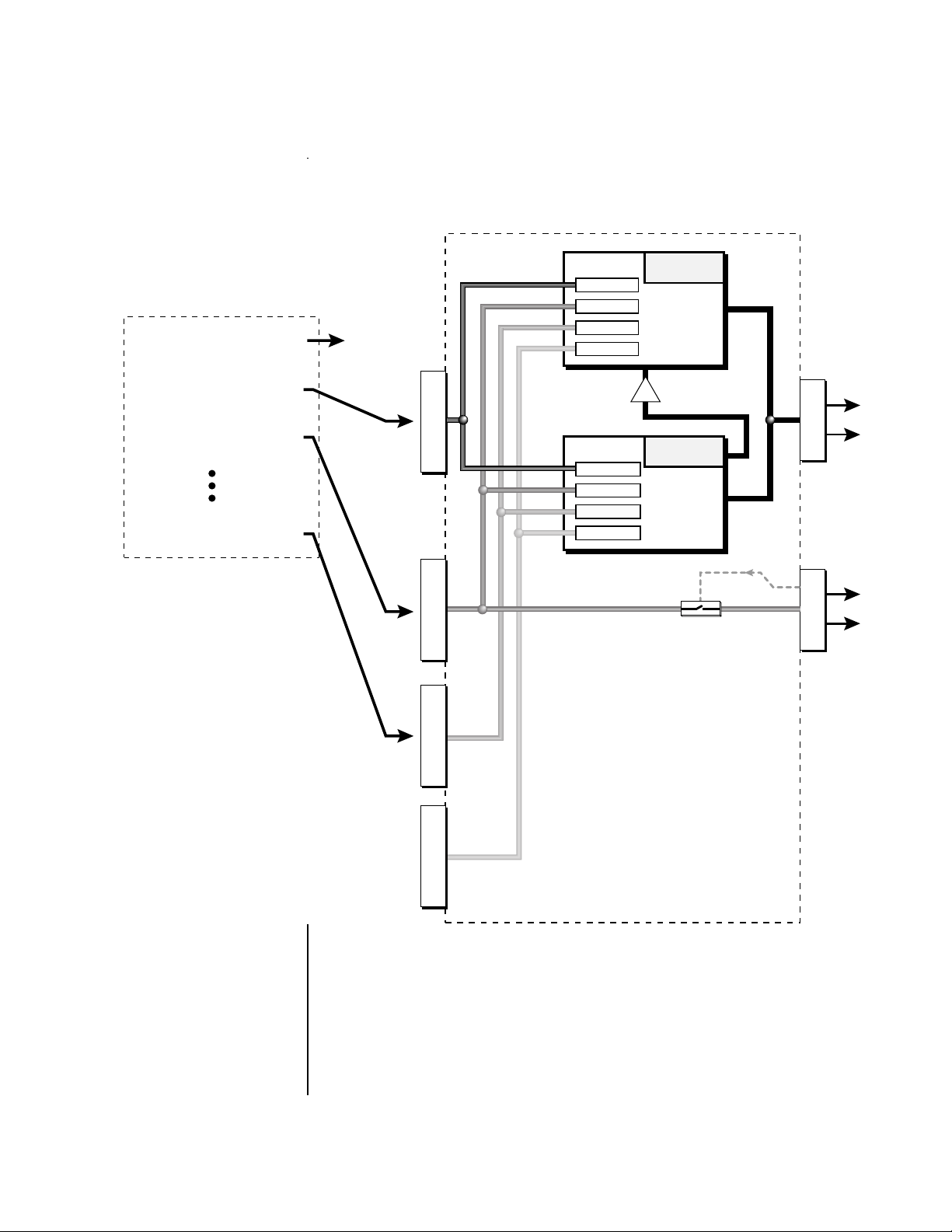
Defining Global Parameters
OUTPUT SECTION
& EFFECTS PROCESSORS
Global Menu
MIDI CHANNEL
MIDI Channel 1
MIDI Channel 2
MIDI Channel 3
MIDI Channel 16
Preset
S
E
N
D
1
S
E
N
D
2
S
E
N
D
3
FX Sends
Send 1 15%
Send 2 10%
Send 3 0%
Send 4 0%
FX Sends
Send 1 0%
Send 2 0%
Send 3 20%
Send 4 15%
Hall 1
Effect
A
B➟A
Chorus
Effect
B
Jack
Detect
M
A
I
N
S
U
B
1
S
E
N
D
4
Send 2 can be routed to the effects processors or to rear panel submix jacks. When a plug
is inserted into a Submix jack, the dry portion of the Send is disconnected from the
effects processor and is routed directly to the Submix output jacks.
XK-6 Owners Manual 87
Page 98
Global Menu
Master Effects
Master Effects The digital effect processors can be programmed as part of the preset (using
the Preset Edit menu) so that effects will change along with the preset.
However, there are only two effect processors, and so you cannot have a
different effect on each preset when in Multi mode.
The Master Effects settings assign the effect processors “globally” for all
presets to provide a way to use the effects in Multi mode. Detailed information is presented in the Effects chapter (see Effects on page 173).
Effects Mode The FX Mode page enables or bypasses the effects. When the FX Mode is set
to “bypass,” the effects are turned off on a global scale. This includes Effects
programmed in the preset.
FX MODE
enabled
Effects Multi Mode Control
The routing scheme for the two stereo effects processors provides a lot of
versatility. When in multi mode, you can “use master settings” which
applies the Master effects settings to all 16 MIDI channels.
FX MULTIMODE CONTROL
use master settings
If you want more control, you can use the “channel” setting which applies
the effects settings of the preset on a specified channel to all the other
channels. Changing the preset on the specified channel changes the effect.
FX MULTIMODE CONTROL
preset on channel 1
If you are in Omni or Poly modes this parameter is disabled and the
message in parentheses explains that XK-6 is currently in Omni mode.
88 E-MU Systems
FX MULTIMODE CONTROL
(using Omni mode)
Page 99
Global Menu
Master Effects
Master FXA Algorithm
This function selects the type of effect used for the “A” effect. The following
effect types are available.
MASTER FXA ALGORITHM
Room 1
A Effect Types
1. Room 1
2. Room 2
3. Room 3
4. Hall 1
5. Hall 2
6. Plate
7. Delay
8. Panning Delay
9. Multitap 1
10. Multitap Pan
11. 3 Tap
12. 3 Tap Pan
13. Soft Room
14. Warm Room
15. Perfect Room
16. Tiled Room
17. Hard Plate
18. Warm Hall
19. Spacious Hall
20. Bright Hall
21. Bright Hall Pan
22. Bright Plate
23. BBall Court
24. Gymnasium
25. Cavern
26. Concert 9
27. Concert 10 Pan
28. Reverse Gate
29. Gate 2
30. Gate Pan
31. Concert 11
32. Medium Concert
33. Large Concert
34. Large Concert Pan
35. Canyon
36. DelayVerb 1
37. DelayVerb 2
38. DelayVerb 3
39. DelayVerb 4 Pan
40. DelayVerb 5 Pan
41. DelayVerb 6
42. DelayVerb 7
43. DelayVerb 8
44. DelayVerb 9
XK-6 Owners Manual 89
Page 100
Global Menu
Master Effects
FXA Parameters: Decay/HF Damping FxB -> FxA
This page lets you define the parameters of the selected Effects algorithm.
Use this page to setup the effect decay, high frequency damping amount
and to route “B” effects through the “A” effects. See “Effect Parameters” on
page 175 for more details.
FXA DECAY HFDAMP FxB>FxA
040 096 001
FXA Send Amounts These parameters set the effects amounts for each of the four stereo effects
busses. See “Master Effects” on page 178 for detailed information.
FXA SEND AMOUNTS 1:100%
2: 50% 3: 10% 4: 0%
Master FXB Algorithm
This parameter selects the type of effect used for the “B” effect. The
following effect types are available.
MASTER FXB ALGORITHM
Chorus 1
90 E-MU Systems
 Loading...