

Page 1

Virtuoso 2000 Owner’s Manual
i
Page 2

Virtuoso 2000
Owner’s Manual
© 2000 E-MU Systems
All Rights Reserved
FI10669 Rev. B
E-MU World Headquarters Europe, Africa, Middle East
E-MU / ENSONIQ E-MU / ENSONIQ
P.O. Box 660015 Suite 6, Adam Ferguson House
Scotts Valley, CA USA Eskmills Industrial Park
95067-0015 Musselburgh, East Lothian
Telephone: 831-438-1921 Scotland, EH21 7PQ
Fax: 831-438-8612 Tel: +44 (0) 131-653-6556
Internet: www.emu.com Fax: +44 (0) 131-665-0473
Important Notice:
In order to obtain warranty service on your Virtuoso 2000 unit, the serial
number sticker must be intact and you must have a sales receipt or other proof
of purchase. If there is no serial number sticker on the Virtuoso 2000, please
contact E-MU Systems at once.
ii
E-MU Systems
This product is covered under one or more of the following U.S. patents:
4,404,529; 4,506,579; 4,699,038; 4,987,600; 5,013,105; 5,072,645;
5,111,727; 5,144,676; 5,170,367; 5,248,845; 5,303,309; 5,317,104;
5,342,990; 5,430,244 and foreign patents and/or pending patents. Virtuoso
2000 is a registered trademarks of E-MU Systems. All other trademarks
belong to their respective companies.
Page 3

Table of Contents
Table of Contents
Introduction ..............................................................................1
Product Description .............................................................................1
Overview ............................................................................................. 2
Important Safety Instructions ..................................................3
Setup .......................................................................................13
Unpacking ......................................................................................... 13
Connection Instructions ..................................................................... 14
Power Up! ................................................................................................ 17
Instant Gratification............................................................................ 18
Playing Demo Sequences .........................................................................18
Auditioning Presets ................................................................................... 18
Selecting and Quick Editing Presets .......................................................... 19
Basic Operations .....................................................................21
Front Panel......................................................................................... 21
Volume Control ........................................................................................ 21
Master Button .......................................................................................... 21
Edit Button ............................................................................................... 21
Control Button ......................................................................................... 21
Audition Button ........................................................................................ 22
Left/Right Cursor Buttons ......................................................................... 22
Multimenu Button .................................................................................... 22
Save/Copy Button .................................................................................... 22
Home/Enter Button .................................................................................. 23
Data Entry Control ...................................................................................23
Controller Knobs ...................................................................................... 23
Front Panel Controller Modes............................................................. 23
Real-time Control ..................................................................................... 23
Quick Edit ................................................................................................24
Deep Edit Mode ....................................................................................... 25
Main Screen....................................................................................... 26
MIDI Channel Selection ............................................................................26
Preset Selection ........................................................................................ 26
Channel Volume ....................................................................................... 27
Channel Pan ............................................................................................. 28
Virtuoso 2000 Owner’s Manual
iii
Page 4

Table of Contents
Sound Navigator................................................................................ 29
Preset Category ........................................................................................29
Instrument Category ................................................................................29
Multitimbral Operation...................................................................... 30
Multimenu .............................................................................. 31
Multisetups........................................................................................ 31
Multichannel Volume ...............................................................................32
Multichannel Pan...................................................................................... 33
Restoring Multisetups ...............................................................................34
Multitimbral Sequencing.................................................................... 36
Master Menu .......................................................................... 37
Defining Master Parameters............................................................... 38
Transpose/Tune ........................................................................................38
Bend Range ..............................................................................................38
Velocity Curve ..........................................................................................39
Mix Output ..............................................................................................40
Master Effects .................................................................................... 42
Effects Mode .............................................................................................42
Effects Multi Mode Control .......................................................................42
Master FXA Algorithm ..............................................................................43
A Effect Types .......................................................................................43
FXA Parameters: Decay/HF Damping FxB -> FxA .......................................44
FXA Send Amounts ...................................................................................44
Master FXB Algorithm ...............................................................................44
B Effect Types .......................................................................................45
FXB Parameters: Feedback/LFO Rate Delay Time .......................................45
FXB Send Amounts ...................................................................................45
MIDI Parameters ................................................................................ 46
MIDI Mode ...............................................................................................46
MIDI SysEx ID ...........................................................................................46
MIDI Enable ..............................................................................................47
MIDI Program Change -> Preset ...............................................................47
Receive Program Change ..........................................................................48
Real-time Controller Assignment ...............................................................48
MIDI Footswitch Assign ............................................................................49
Tempo Controller .....................................................................................50
Knob Preset Quick-Edit .............................................................................50
Knobs Deep Edit .......................................................................................51
Knobs/Riff MIDI Out .................................................................................51
Preset Edit All Layers Enable ......................................................................51
Front Panel Knob Calibration ....................................................................52
MIDI SysEx Packet Delay ...........................................................................53
Send MIDI System Exclusive Data .............................................................53
User Key Tuning .......................................................................................55
iv E-MU Systems
Page 5

Table of Contents
Output Format ......................................................................................... 55
Base Tempo .............................................................................................56
Screen Viewing Angle ............................................................................... 56
Programming Basics ...............................................................57
Modulation ........................................................................................ 58
Modulation Sources ........................................................................... 59
Random Sources ......................................................................................60
Modulation PatchCords...................................................................... 60
Envelope Generators .......................................................................... 61
Tempo-based Envelopes ....................................................................... 62
Envelope Repeat ................................................................................... 62
Low Frequency Oscillators (LFOs)....................................................... 63
Clock Modulation............................................................................... 64
Modulation Destinations .................................................................... 66
Modulation Processors ....................................................................... 67
Preset Modulation Processors ............................................................. 69
Using the Modulation Processors .............................................................. 71
More Examples .........................................................................................73
Dynamic Filters ..................................................................................75
What is a Filter? ........................................................................................ 76
Parametric Filters ...................................................................................... 79
The Z-Plane Filter .....................................................................................80
Signal Flow ........................................................................................ 81
MIDI Channels & Real-time Controls.................................................. 82
Bank Select Commands ............................................................................ 84
Stereo Mix Outputs............................................................................ 85
Edit Menu ................................................................................87
Preset Name ............................................................................................. 88
Four Layer Architecture ...................................................................... 89
Selecting Layers ........................................................................................ 89
Defining Layer
Parameters......................................................................................... 90
Selecting an Instrument ............................................................................ 90
Sound Navigator .................................................................................. 90
Defining Key Range .................................................................................. 91
Defining the Velocity Crossfade Range ......................................................94
Defining the Real-time Crossfade Range ................................................... 96
Transposing the Instrument ...................................................................... 99
Tuning ...................................................................................................100
Virtuoso 2000 Owner’s Manual v
Page 6

Table of Contents
Background: Transpose vs. Coarse Tuning ..........................................100
Amplifier .................................................................................................100
Volume Envelope ....................................................................................101
Selecting the Mode ............................................................................101
Defining the Volume Envelope ...........................................................102
Chorusing the Layer ...............................................................................103
Sound Start Offset and Delay ..................................................................103
Non-Transpose Mode .............................................................................104
Solo Mode ..............................................................................................104
Assign Group ..........................................................................................105
Glide ......................................................................................................106
Z-Plane Filters .........................................................................................106
Virtuoso 2000 Filter Types ......................................................................110
Filter Parameters .................................................................................110
Filter Envelope ........................................................................................110
Envelope Repeat .................................................................................111
Defining the Filter Envelope ................................................................112
Auxiliary Envelope ..................................................................................112
Low Frequency Oscillators (LFOs) ...........................................................112
Shape .................................................................................................113
Sync ...................................................................................................114
Rate ....................................................................................................114
Delay ..................................................................................................115
Variation .............................................................................................116
PatchCords .............................................................................................117
Modulator Polarity ..............................................................................118
Pitch Bend Range ...................................................................................120
Mix Output .............................................................................................120
Common Preset Parameters............................................................. 121
Preset Effects ..........................................................................................121
FXA Algorithm ........................................................................................123
A Effect Types .....................................................................................123
FXA Parameters ......................................................................................124
FXA Send Amounts .................................................................................124
FXB Algorithm ........................................................................................124
B Effect Types .....................................................................................124
FXB Parameters .......................................................................................125
FXB Send Amounts .................................................................................125
Preset Patchcords ...................................................................................125
Initial Controller Amount ........................................................................127
Keyboard Tuning ....................................................................................128
Preset Links .............................................................................................130
Preset Tempo Offset ...............................................................................131
Audition Riff Selection .............................................................................131
Play Solo Layers ......................................................................................131
vi E-MU Systems
Page 7

Table of Contents
Programming Tutorial ..........................................................133
Editing Presets.................................................................................. 133
Changing the Instrument ....................................................................... 133
Changing the Tuning of an Instrument ..................................................134
Chorus ...................................................................................................135
Volume Envelope ...................................................................................135
Working with Filters ...............................................................................137
Adding the Filter Envelope .................................................................138
Changing Filter Types ........................................................................140
Envelope Repeat ................................................................................. 141
Practice Modulating ............................................................................... 141
Troubleshooting .....................................................................................142
Linking Presets .................................................................................143
Using External Processing ....................................................................... 144
Effects ....................................................................................145
Effects Overview............................................................................... 145
The Effects Sends .................................................................................... 145
Effect Types...................................................................................... 147
Effect Parameters .................................................................................... 147
Decay ................................................................................................148
High Frequency Damping .................................................................. 148
Feedback ............................................................................................148
LFO Rate ............................................................................................ 148
Delay .................................................................................................148
Effects Programmed in the Preset..................................................... 149
Master Effects................................................................................... 150
Effects Mode ..........................................................................................152
Flexible Effects Control ........................................................................... 152
Using the Effects Channel Settings in Multi Mode ..............................154
Effect B Into Effect A ............................................................................... 154
General Effect Descriptions............................................................... 156
Reverb ....................................................................................................156
Chorus ...................................................................................................157
Doubling ................................................................................................157
Slapback .................................................................................................157
Stereo Flanger ........................................................................................ 157
Delay ......................................................................................................158
Stereo Delay ...........................................................................................158
Panning Delay ........................................................................................ 158
Dual Tap ................................................................................................158
Vibrato ...................................................................................................158
Distortion ...............................................................................................158
Virtuoso 2000 Owner’s Manual vii
Page 8

Table of Contents
Save/Copy Menu .................................................................. 159
Saving a Preset................................................................................. 159
Copying Information ....................................................................... 160
Copy Preset ............................................................................................160
Copy Layer .............................................................................................160
Copy PatchCords ....................................................................................161
Copy Preset PatchCords ..........................................................................162
Copy Preset Bank ....................................................................................162
Create Random Preset ............................................................................163
Copy User Bank to Flash .........................................................................164
Rename Flash SIMM ...............................................................................165
Duplicate Flash .......................................................................................166
Appendix .............................................................................. 167
Front Panel Knob Functions ............................................................. 167
Presets ............................................................................................. 168
Virtuoso Preset Categories ......................................................................168
13th Row Sampling ................................................................................168
Instrument Placement............................................................................. 168
Preset Listing.................................................................................... 169
Riff Listing........................................................................................ 173
Instrument Listing............................................................................ 175
Instrument Categories ............................................................................175
Instrument Suffix Definitions ...................................................................177
Velocity Curves ................................................................................ 178
PatchCord Amount Chart ................................................................ 180
MIDI ................................................................................................ 181
Technical Specifications.................................................................... 183
Warranty.......................................................................................... 184
The Making of Virtuoso ................................................................... 186
Index .................................................................................... 187
viii E-MU Systems
Page 9

Introduction
Congratulations on your purchase of the E-MU Systems Virtuoso 2000 – the
orchestrator’s dream machine. The power of Virtuoso 2000 begins with it’s
stunning, 64 MB orchestral soundset—from solo and section strings to
brass, woodwinds and percussion—all sampled from the same orchestra
under ideal recording conditions. To complete your symphony orchestra,
Virtuoso gives you 128 voice polyphony, which means that up to 128
different instrument lines can be played at once! With all these voices, 16
MIDI channels didn’t seem to be quite enough, so we added another MIDI
input jack to allow 32 MIDI channel operation. As long as we were going
for the gold, we decided to add the ability to access 128MB of sound
memory on user upgradable SIMMs. And there’s much more as you will
soon discover.
Product Description
Virtuoso 2000 contains four user-upgradable sound SIMM sockets, allowing
you to mix and match sound sets according to your needs. New sounds can
be added as easily as plugging in a new 16MB or 32MB SIMM module and
up to 128MB of sounds can be added! Each sound set has been meticulously
crafted to be the best of its kind. Samples are matched across the keyboard,
perfectly looped, and rich in harmonic texture.
Virtuoso 2000 contains 512 user presets and can hold literally thousands of
factory presets. (ROM presets are automatically added when sound SIMMs are
installed. As an example, a 32 MB SIMM may contain up to 1024 ROM presets.)
Virtuoso 2000’s Sound Navigator is a major innovation for the main screen
which makes it easy to find the exact sound you want from the thousands
available. It’s powerful, yet simple to use.
Of course the real power of Virtuoso 2000 becomes apparent when you
synthesize your own sounds. The extremely flexible yet easy to use, 4-layer
synthesizer voices make it easy to build sounds and textures. Layers can be
switched or crossfaded using key position, velocity, real-time controllers or
any modulation source. Virtuoso 2000 also contains 50 different types of
2nd to 6th order resonant & modeling filters which can be used to shape
and modify the orchestral waveforms for musical expression and control.
Virtuoso 2000 Owner’s Manual 1
Page 10

Introduction
Overview
2
The 64 modulation sources include three multistage envelopes and two
LFOs per layer, as well as full MIDI control over virtually every parameter.
The digital patch bay, with 24 cords per layer, (and 12 more cords per
preset) lets you connect modulation sources to 64 destinations in any
imaginable way.
The patch bay contains a set of arithmetic modifiers, allowing you to create
complex synthesis models.
Four front panel real-time controllers give you control over 12 userselectable parameters. The real-time knobs can adjust multiple synthesizer
functions at once, allowing complex levels of control. For example, one
knob can simultaneously turn up filter cutoff, while detuning one sample,
and adjusting the release time of the volume envelope. Virtually every
synth parameter in the Virtuoso is controllable using the real-time knobs or
by any internal or external control source.
Six 20-bit analog outputs let you process separate sounds and integral effect
sends externally. Returns allow the addition of external effects units
without the need for a separate mixer.
Once you have created your preset, you can add room ambience and
richness to your sound using Virtuoso 2000’s 24-bit stereo effects. You can
choose a different effects setup for each preset from over 60 algorithms.
Virtuoso’s effects section is actually two separate effects processors with
control over each wet/dry mix level. Effects Processor “A” contains
primarily ambiance algorithms like reverb and delays, while effects
processor “B” contains primarily spectral algorithms such as chorus, flange,
phase, distortion, and delay. Effects can be linked to each preset or used
globally to further enhance your sound.
The S/PDIF digital stereo output lets you connect to other digital
equipment, such as digital mixers or external effects devices, keeping your
signal entirely in the digital domain.
Other features include multiple solo, voice assignment and performance
modes for expressive control, 12 user-definable alternate tunings, an
extremely easy to use interface and, of course, an extensive MIDI
implementation.
Overview
E-MU Systems
This is the Operation Manual for setting up and playing Virtuoso 2000. The
first part of the manual describes how to unpack and setup the hardware.
The next chapters provide step-by-step instructions for the most common
and widely used features of Virtuoso. This section also defines each of the
parameters (by menu) and provides information on how to use them.
The appendix provides technical information, product specifications and
the Index.
Page 11

Important Safety Instructions
Use in countries other than the U.S.A. may require the use of a different
line cord or attachment plug, or both. To reduce the risk of fire or electric
shock, refer all servicing to qualified service personnel. Do not expose this
product to rain or moisture. There are no user serviceable parts or adjustments inside the unit.
Grounding Instructions
Danger!
Caution!
This product must be grounded. If it should malfunction or break down,
grounding provides a path of least resistance for electric current, reducing
the risk of electric shock. This product is equipped with a cord having an
equipment-grounding conductor and a grounding plug. The plug must be
plugged into an appropriate outlet properly installed and grounded in
accordance with all local codes and ordinances.
Improper connection of the equipment’s grounding conductor can result in
the risk of electric shock. Check with a qualified electrician or service
personnel if you are in doubt as to whether the product is properly
grounded. Do not modify the plug provided with this product. If it will not
fit the outlet, have a proper outlet installed by a qualified technician.
If your Virtuoso 2000 (Model Number 9096) is rack mounted, you must use
a standard 19 inch open frame rack. Screw-on rack mount ears are provided
for this purpose.
Virtuoso 2000 Owner’s Manual 3
Page 12
Important Safety Instructions
User Maintenance Instructions
User Maintenance Instructions
4
1.
The Virtuoso 2000 should be kept clean and dust free. Periodically wipe
the unit with a clean, lint free cloth. Do not use solvents or cleaners.
2.
There are no user lubrication or adjustment requirements.
Caution -.
These servicing instructions are for use by qualified personnel only. To
reduce the risk of electric shock, do not perform any servicing other than that
contained in these operating instructions unless you are qualified to do so. Refer
all servicing to qualified service personnel.
INSTRUCTIONS PERTAINING TO A RISK OF FIRE,
ELECTRIC SHOCK, OR INJURY TO PERSONS.
READ THESE INSTRUCTIONS: When using electric products, basic precau-
tions should always be adhered to, including the following:
This symbol is intended to
alert you to the presence of
important operating and
maintenance (servicing)
instructions in the literature
accompanying the unit.
This symbol is intended to
alert you to the presence of
uninsulated dangerous
voltage within the product’s
enclosure that may be of
sufficient magnitude to
constitute a risk of electric
shock to persons.
Read all instructions before using Virtuoso 2000.
1.
To reduce the risk of injury, close supervision is necessary when using
2.
Virtuoso 2000 near children.
Do not use Virtuoso 2000 near water — for example near a bathtub,
3.
washbowl, kitchen sink, in a wet basement, on a wet bar, or near or in a
swimming pool. Do not expose the unit to drips or splashes.
The Virtuoso 2000 should be situated so that its location or position
4.
does not interfere with its proper ventilation.
The Virtuoso 2000 should be located away from heat sources such as
5.
radiators, heat registers, fireplaces, stoves, or ovens.
The Virtuoso 2000 should be connected only to a power supply of the
6.
type described in the operating instructions and marked on the
product.
Care should be taken so that objects do not fall and liquids are not
7.
spilled into the enclosure of Virtuoso 2000 through openings.
This Virtuoso 2000 may be equipped with a polarized line plug (one
8.
blade wider that the other). This is a safety feature. If you are unable to
insert this plug into the outlet, do not defeat the safety purpose of the
plug. Contact an electrician to replace your obsolete outlet.
Protect the power cord from being walked on or pinched, particularly at
9.
plugs, convenience receptacles, and the point where they exit from the
unit.
Unplug the Virtuoso 2000 from the power outlet during lightning
10.
storms or when left unused for a long period of time.
This product, in combination with an amplifier and headphones and
11.
speakers, may be capable of producing sound levels that could cause
permanent hearing loss. Do not operate for a long period of time at a
high volume level or at a level that is uncomfortable. If you experience
any hearing loss or ringing in the ears, consult an audiologist.
Only use attachments and accessories specified by E-MU Systems.
12.
E-MU Systems
Page 13

•
•
•
•
•
Important Safety Instructions
Radio and Television Interference
The Virtuoso 2000 should be serviced by qualified service personnel
13.
when:
A. The power supply cord has been damaged; or
B. Objects have fallen, or liquid has been spilled into the unit; or
C. The unit has been exposed to rain; or
D. The unit has been dropped or the enclosure damaged; or
E. The Virtuoso 2000 does not operate normally or exhibits a marked
change in performance.
All servicing should be referred to qualified service personnel.
14.
Radio and
Television
Interference
Save These Instructions.
The equipment described in this manual generates and uses radiofrequency energy. If it is not installed and used properly —that is, in strict
accordance with our instructions— it may cause interference with radio
and television reception.
This equipment has been tested and complies with the limits for a Class B
computing device in accordance with the specifications in Subpart J of Part
15 of the FCC rules. These rules are designed to provide reasonable
protection against such interference in a residential installation. However,
there is no guarantee that the interference will not occur in a particular
installation, especially if a “rabbit ear” TV antenna is used.
If Virtuoso 2000 does cause interference to radio or television reception,
you can try to correct the interference by using one or more of the
following measures:
Turn the television or radio antenna until the interference stops.
Move Virtuoso 2000 to one side or the other of the television or radio.
Move Virtuoso 2000 farther away from the television or radio.
Plug Virtuoso 2000 into an outlet on a different circuit than the televi-
sion or radio.
Consider installing a rooftop antenna with a coaxial lead-in between the
antenna and television set.
Virtuoso 2000 Owner’s Manual 5
Page 14

Foreign Language Warnings - German
Wichtige Sicherheitsvorschriften
Foreign Language Warnings
- German
6
Wichtige
Sicherheitsvorschriften
Erdungsinstruktionen
Gefahr
In Ländern ausserhalb den U.S.A. können andere Kabel oder Stecker
notwendig werden. Zur Verminderung des Risikos von Feuer oder eines
elektrischen Schlages übergebe man den Service an qualifizierte Fachleute.
Das Gerät niemals Regen oder Nässe aussetzen.
Das Gerät muss geerdet sein. Bei einem Defekt oder Ausfall bietet Erdung
dem elektrischen Strom den Weg des geringsten Widerstandes und
reduziert das Risiko eines Schlages. Dieses Gerät ist mit einem geerdeten
Kabel und Stecker ausgerüstet. Der Stecker muss in eine passende,
einwandfrei montierte und geerdete Steckdose in Übereinstimmung mit
den örtlichen Vorschriften eingeführt werden.
Unvorschriftsgemässer Anschluss des Gerätes kann zum Risiko eines
elektrischen Schlages führen. Im Zweifelsfalle über die ordnungsgemässe
Erdung soll ein qualifizierter Elektriker oder eine Serviecestelle beigezogen
werden. Ändern Sie den mitgelieferten Stecker nicht. Sollte er nicht in die
Steckdose passen, soll die einwandfreie Installation durch einen qualifizierten Techniker erfolgen.
Vorsicht
E-MU Systems
Wird der Virtuoso 2000 (Modell Nummer 9096) in einem Rackgestell
montiert, muss ein offener 19-Zollrahmen verwendet werden.
Page 15
Unterhaltsinstruktionen
für anwender
Foreign Language Warnings - German
Unterhaltsinstruktionen für anwender
1.
Virtuoso 2000 soll sauber und staubfrei gehalten werden. Das Gerät mit
einem sauberen und säurefreien Tuch periodisch abreiben. Keine
Lösungs- oder Reinigungsmittel anwenden.
2.
Schmieren und Justieren sind nicht notwendig.
3.
Bei weiteren Servicefragen wende man sich an eine qualifizierte Servicestelle.
Vorsicht
Dieses Symbol weist den
Anwender auf wichtige
Gebrauchs- und Service-
Vorschriften in den beilieg-
enden Drucksachen.
Dieses Symbol verweist auf
nicht-isolierte Stromspannungen im Geräte-Innern,
welche zu einem elektrischen
Schlag führen könnten.
Diese Gebrauchsanweisungen sind nur für qualifizierte Techniker
beabsichtigt. Um die Gefahr eines elektrischen Schlages zu vermeiden,
sollen Sie keine Arbeit unternehmen, die nicht in diesen Instruktionen
vorgeschrieben ist. Wenden Sie Sich bei weiteren Servicefragen an eine
qualifizierte Servicestelle.
INSTRUKTIONEN BETR. FEUERRISIKO,
ELEKTROSCHOCK ODER VERLETZUNG VON
PERSONEN
WARNUNG; Beim Einsatz elektrischer Geräte sollten
folgende Vorsichtsmassregeln stets beachtet werden:
1.
Lesen Sie vor dem Einschalten des Virtuoso 2000 alle Instruktionen.
2.
Zur Vermeidung von Verletzungsrisiken müssen Kinder bei eingeschaltetem Virtuoso 2000 sorgfältig überwacht werden.
3.
Virtuoso 2000 nicht in der Nähe von Wasser in Betrieb nehmen -- z.B.
in der Nähe von Badewannen, Waschschüsseln, auf nassen Gestellen
oder am Swimmingpool.
4.
Virtuoso 2000 stets so aufstellen, dass seine Belüftung nicht beeinträchtigt wird.
5.
Virtuoso 2000 nicht in der Nähe von Hitze aufstellen, wie Heizkörper,
offenem Feuer, Öfen oder von Backöfen.
6.
Virtuoso 2000 ausschliesslich mit einem Netzgerät gemäss Bedienungsanleitung und Gerätemarkierung verwenden.
7.
Dieses Gerät kann bei Verwendung von Kopfhörern und Verstärkern
hohe Lautpegel erzeugen, welche zu bleibenden Gehörschäden führen.
Arbeiten Sie nicht während längerer Zeit mit voller Lautstärke oder
hohem Lautpegel. Stellen Sie Gehörverlust oder Ohrenläuten fest,
wenden Sie sich an einen Ohrenartz.
8.
Virtuoso 2000 kann mit einem polarisierten Kabelstecker (mit ungleichen Stiften) ausgerüstet sein. Das geschieht für Ihre Sicherheit.
Können Sie den Stecker nicht in die Steckdose einführen, ändern Sie
nicht den Stecker ab, sondern wenden Sie sich an einen Elektriker.
9.
Das Netzkabel des Virtuoso 2000 bei längerem Nichtgebrauch aus der
Steckdose ziehen.
Virtuoso 2000 Owner’s Manual 7
Page 16

Foreign Language Warnings - German
10.
11.
12.
Vermeiden Sie sorgfältig das Eindringen von Gegenständen oder
Flüssigkeiten durch die Gehäuseöffnungen.
Das Gerät soll durch qualifizierte Serviceleute gewartet werden, falls:
A. das Netzkabel beschädigt wurde, oder
B. Gegenstände oder Flüssigkeit in das Gerät gelangten,
C. das Gerät Regen ausgesetzt war, oder
D. das Gerät nicht normal oder einwandfrei arbeitet, oder
E. das Gerät stürzte oder sein Gehäuse beschädigt wurde.
Servicearbeiten sollten nur qualifizierten Fachleuten anvertraut werden.
8
DIESE INSTRUKTIONEN AUFBEWAHREN
E-MU Systems
Page 17

Foreign Language Warnings - French
Instructions de Sécurité Importantes
Foreign Language Warnings
- French
Instructions
de Sécurité
Importantes
Instructions de Mise à la Terre
Danger
Une utilisation dans des pays autres que les U.S.A. peut nécessiter l’usage
d’un cordon d’alimentation différent. Afin de réduire les risques d’incendie
ou d’électrocution, référez-vous à un personnel de service qualifié, et
n’exposez pas cet appareil à la pluie ou à l’humidité.
Cet appareil doit être relié à la terre. Dans le cas d’une malfonction
éventuelle, la terre fournit un passage de moindre résistance pour le
courant électrique, réduisant ainsi les risques d’électrocution. Le Virtuoso
2000 est équipé d’un cordon muni d’un conducteur et d’une fiche devant
être branchée dans une prise appropriée et reliée à la terre en conformité
avec les normes locales.
Une connexion incorrecte peut résulter en des risques d’électrocution.
Vérifiez avec un technicien qualifié si vous avez des doutes quant à la
connexion. Ne modifiez pas vous-même le cordon d’alimentation livré avec
cet appareil; s’il ne rentre pas dans la prise, faites-en installer un autre par
un technicien qualifié.
Attention
Instructions de Maintenance
Si le Virtuoso 2000 est installé dans un rack, utilisez un rack standard ouvert
de 48.25cm.
1.
le Virtuoso 2000 doit être maintenu propre et sans poussière. Nettoyezle périodiquement à l’aide d’un chiffon propre et non-pelucheux.
N’utilisez pas de solvants, ou d’autres produits de nettoyage.
2.
Aucune lubrification et aucun réglage ne sont nécessaires de votre part.
3.
Pour tout autre service, référez-vous à un personnel qualifié.
Virtuoso 2000 Owner’s Manual
9
Page 18
Foreign Language Warnings - French
Instructions de Maintenance
Instructions Concernant les Risques d’Incendie,
d’Electrocution, ou de Blessures Corporelles.
ATTENTION: Lorsque vous utilisez des appareils électriques,
certaines précautions élémentaires doivent toujours être prises,
incluant les suivantes:
Ces instructions de dépanage sont destinées uniquement aux personnes
qualifiées. Afin d’éviter les risques d’électrocution, n’effectuez que les opérations décrites dans ce manuel, à moins que vous ne soyez qualifiê pour cela.
Faites effectuer toute r’eparation par une personne qualifié.
1. Lisez bien toutes les instructions avant d’utiliser le Virtuoso 2000.
2. Afin de réduire les risques de blessures, une attention particulière est
3. N’utilisez pas le Virtuoso 2000 dans ou près d’endroits humides - par
Ce symbole vous alerte de la
présence d’instructions
importantes d’opération et
de maintenance dans la
notice accompagnant
l’appareil.
Ce symbole vous alerte de
la présence d’un voltage
non-isolé dangereux à
l’intérieur de l’appareil,
pouvant être d’une
magnitude suffisante pour
constituer un risque
d’électrocution.
4. Le Virtuoso 2000 doit être placé de façon à ce que sa position n’interfére
5. Le Virtuoso 2000 doit être placé loin de sources de chaleur telles que des
6. Le Virtuoso 2000 doit uniquement être connecté à une alimentation du
7. Une attention particulière doit être observée quant aux objets pouvant
8. Le Virtuoso 2000 peut être équipé d’une fiche secteur polarisée (avec
9. Evitez de marcher sur le cordon d’alimentation ou de le coincer, parti-
10. Le cordon d’alimentation de le Virtuoso 2000 doit être débranché
11. Cet appareil, combiné avec un amplificateur, des haut-parleurs, et/ou
12. N’utilisez que les accessoires sp’ecifi’es par E-MU Systems.
nécessaire en la présence d’enfants en bas âge.
exemple près d’une baignoire, d’un lavabo, dans les toilettes, dans une
cave humide, sur un bar fréquenté, en présence d’un bull-dog en rut, ou
dans une piscine pleine. Protégez cet appareil de tout liquide,
éclaboussure ou fuite.
pas avec sa propre ventilation.
radiateurs, cheminées, fours, ou groupies en chaleur.
type décrit dans les instructions d’opération et tel qu’indiqué sur
l’appareil.
tomber et aux liquides pouvant être versés sur et à l’intérieur de le
Virtuoso 2000.
une broche plus large que l’autre). C’est une mesure de sécurité. Si vous
ne pouvez pas brancher cette fiche dans une prise, ne neutralisez pas
cette sécurité. Contactez plutôt un électricien pour remplacer la prise
obsolète.
culiêrement prês des prises de courant, des boitiers ‘electriques dt du
point de sortie de l’appareil.
lorsque ce dernier n’est pas utilisé pendant une longue période.
un casque, est capable de générer des niveaux sonores pouvant
occasionner une perte de l’ouïe permanente. Ne travaillez pas trop
longtemps à un volume trop élevé ou même inconfortable. Si vous
observez une perte de l’audition ou un bourdonnement dans les
oreilles, consultez un O.R.L.
10
E-MU Systems
Page 19

Foreign Language Warnings - French
Interférences Radio et Télévision
13. Cet appareil doit être examiné par un personnel qualifié lorsque:
A. Le cordon d’alimentation a été endommagé, ou
B. Des objets sont tombés, ou du liquide a été versé sur/à l’intérieur
de l’appareil, ou
C. Le Virtuoso 2000 a été exposé à la pluie, ou
D. Le Virtuoso 2000 est tombé, ou
E. Le Virtuoso 2000 ne fonctionne pas normalement, ou affiche un
changement radical de performance.
14. Tout service doit être effectué par un personnel qualifié.
SAUVEGARDEZ CES INSTRUCTIONS
Interférences
Radio et
Télévision
L’appareil décrit dans cette notice génére et utilise une énergie de
fréquence-radio. S’il n’est pas installé et utilisé correctement - c’est à dire en
suivant strictement nos instructions - il peut occasionner des interférences
avec la réception d’une radio ou d’une télévision.
Cet appareil a été testé et est conforme aux normes de Classe A en accord
avec les spécifications du paragraphe J de la section 15 des lois FCC. Ces lois
sont désignées pour fournir une protection raisonnable contre de telles
interférences dans une installation résidentielle. Toutefois, il n’est pas
garanti qu’aucune interférence n’apparaisse dans des installations particulières, et plus spécialement lorsqu’une antenne de télévision en «oreilles de
lapin» est utilisée.
Si le Virtuoso 2000 occasionne des interférences , vous pouvez essayer de les
corriger en utilisant une ou plusieurs des mesures suivantes:
• Tournez l’antenne de la télé ou de la radio jusqu’à ce que les inter-
férences disparaissent.
• Déplacez le Virtuoso 2000 d’un côté ou de l’autre de la télé ou de la
radio.
• Eloignez le Virtuoso 2000 de la télé ou de la radio.
• Branchez le Virtuoso 2000 sur une prise différente que la télé ou la radio.
• Installez une antenne sur le toit munie d’une connexion coaxiale entre
elle et le poste de télévision.
Virtuoso 2000 Owner’s Manual 11
Page 20

Foreign Language Warnings - French
Interférences Radio et Télévision
12 E-MU Systems
Page 21

Setup
This section thoroughly describes how to set up your new Virtuoso 2000 for
use. Setup includes unpacking instructions and how to connect cables to
Virtuoso 2000.
Unpacking Carefully remove Virtuoso 2000 from the packaging material. Take care to
save the packing materials in case you need to transport the unit. Check to
make sure all components are included and in good condition. If there are
missing or damaged components, contact E-MU Systems immediately for
replacement or repair.
The Virtuoso 2000 box should include the following components:
• Virtuoso 2000 unit
• Power cable
• Rack mounting ears
• This Operation Manual
Virtuoso 2000 Owner’s Manual 13
Page 22
Setup
SCOTTS V
ALLEY CA. U.S.A.
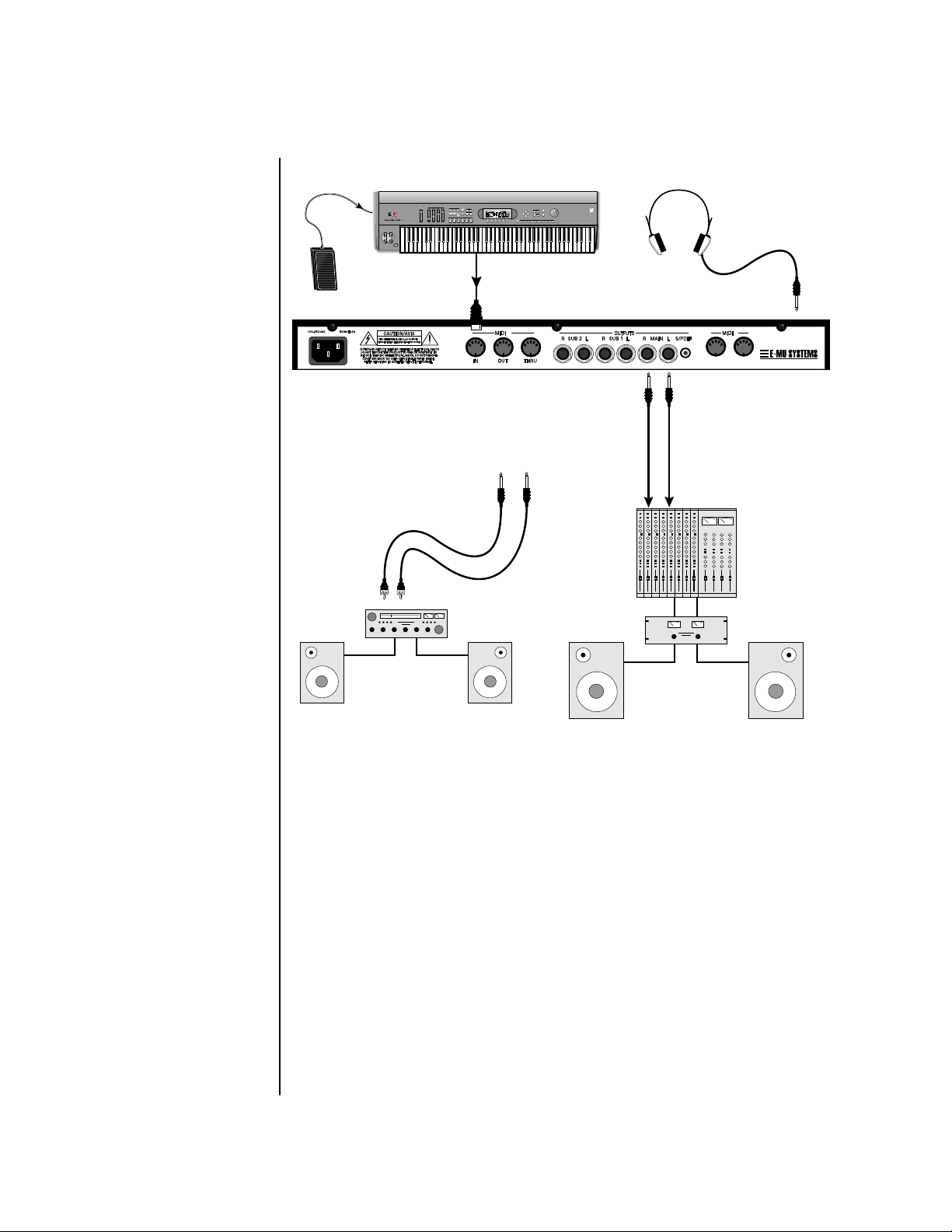
Connection Instructions
Connection
Instructions
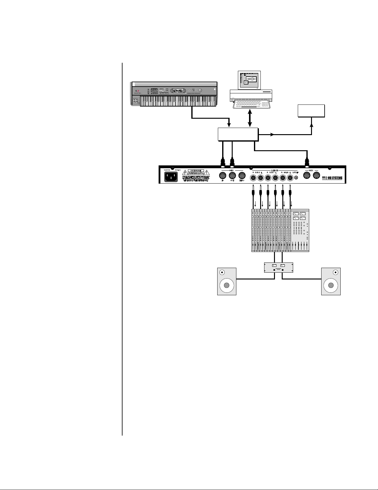
Basic Setup
If Virtuoso 2000 does
not seem to be responding
correctly, make sure that both
Virtuoso 2000 and your MIDI
controller are set to the same
MIDI channel.
~
Control
Pedal
Aux. or
Tape In
MIDI Controller
(MIDI Keyboard, Sequencer, etc.)
REAL TIME CONTROLLERS
ASSIGNABLE KEYS
PRESET
SAMPLE
SEQUENCER
EMULATOR
MIDI Out
Main Outs
Male RCA plug
to
Male Phono Plug
A
To
LEVEL
EXIT
ENTER
PAGE
PRESET SELECT
RETURN
0.987654321
Main Outs to Mixer In
The Headphone
Output is located
on the Front Panel
B
IN THRU
Mixer
SCOTTS V
ALLEY CA. U.S.A.
Amp
Speakers
Home Stereo
System
Home Studio
System
MIDI In
Virtuoso 2000 is controlled by MIDI messages received at the MIDI A jack.
Normally you will connect MIDI Out of a controller such as a MIDI
keyboard, MIDI wind controller or MIDI guitar controller to the MIDI A
jack of Virtuoso 2000 .
Outputs
Virtuoso 2000 is a high quality, stereo audio device. In order to reproduce
its wide dynamic range and frequency response, use a high quality amplification and speaker system such as a keyboard amplifier or home stereo
system. A stereo setup is highly desirable because of the added realism of
stereophonic sound. Headphones can be used if an amplifier and speaker
system is not available. Plug stereo headphones into the headphone jack
located on the left side of the front panel. The Right Main output jack
serves as a mono output when the Left Main plug is not plugged in. The
Left Main output jack is a stereo jack carrying both channels.
The S/PDIF output duplicates the function of the main output.
14 E-MU Systems
Page 23
Studio Setup
SCOTTS V
ALLEY CA. U.S.A.
THRU
MIDI Controller
(MIDI Keyboard, Sequencer, etc.)
REAL TIME CONTROLLERS
ASSIGNABLE KEYS
PRESET
SAMPLE
SEQUENCER
~
Setup
Connection Instructions
LEVEL
EXIT
ENTER
PAGE
PRESET SELECT
RETURN
EMULATOR
0.987654321
Computer
MIDI Out
In
MIDI
Interface
Out
“A” MIDI
channels
1-16
A
Computer
Additional
MIDI
Devices
MIDI In
Out
OutIn
“B” MIDI
channels
1-16
B
SCOTTS V
IN THRU
ALLEY CA. U.S.A.
Mixer
Amp
MIDI In
In this setup, Virtuoso 2000 is controlled by MIDI messages, received at
both MIDI A and MIDI B inputs, which are routed by the MIDI interface.
Each MIDI input handles 16 MIDI channels for a total of 32 channels. The
MIDI interfaces allow any MIDI controller, such as a MIDI keyboard or a
computer, to control the module.
MIDI Out
The MIDI Out jack transmits program data to a computer or other device.
Outputs
Three sets of programmable stereo outputs (Main, Sub 1, and Sub 2) are
provided. The internal effects are available only on the Main outputs.
Specific presets (or MIDI channels) can be routed to one of these stereo
pairs in order to be processed further or mixed separately. The S/PDIF
output duplicates the function of the main output.
Virtuoso 2000 Owner’s Manual 15
Page 24
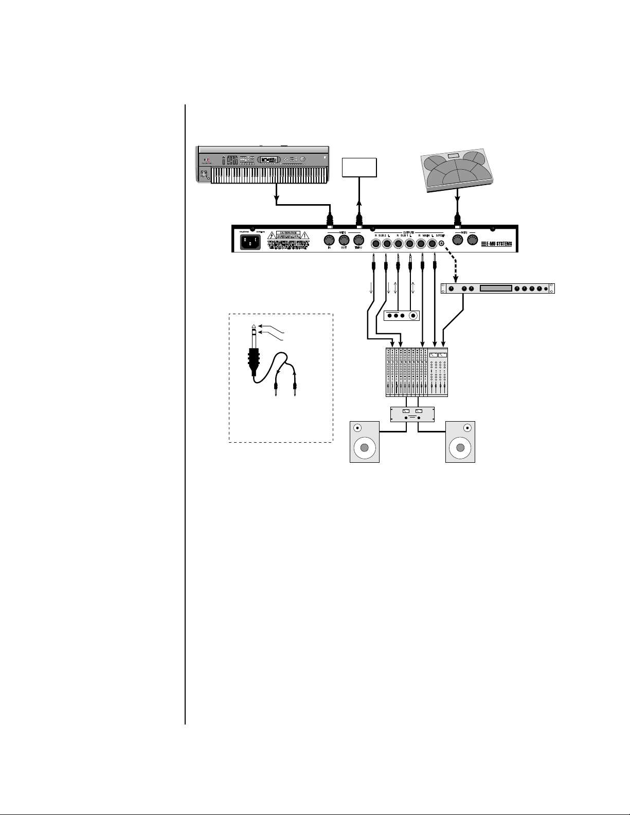
Performance Setup
SCOTTS V
ALLEY CA. U.S.A.
Setup
Connection Instructions
MIDI Controller
(MIDI Keyboard, Sequencer)
REAL TIME CONTROLLERS
ASSIGNABLE KEYS
PRESET
SAMPLE
SEQUENCER
~
To Effect From Effect
SEND/RETURN CABLE
Signal is sent out on tip of plug and
returned to main outputs via ring of plug.
LEVEL
EXIT
ENTER
PAGE
PRESET SELECT
EMULATOR
MIDI Out
Sub Output
Return
(To Main Output)
Tip Ring
MIDI Controller
(MIDI Percussion Controller)
RETURN
0.987654321
Additional
MIDI
Device
MIDI In
MIDI Out
A
Send
Send/Return
Effect Device
Main Outs to Mixer In
B
SCOTTS V
S/PDIF In
ALLEY CA. U.S.A.
Effect: Swirling Reverb
Parameter Edit
Digital Effect
IN THRU
Volume Mix Data Entry Control 1 Control 2 Control 3 Control 4
Analog Out
16 E-MU Systems
MIDI In
Virtuoso 2000 is controlled by MIDI messages received at either MIDI
input. In a live performance situation, you might want to use two MIDI
controllers as shown above. Connect MIDI outputs of your MIDI
controllers such as a MIDI keyboard, MIDI drum pads or a MIDI sequencer
to MIDI Inputs A and B of Virtuoso 2000.
MIDI Thru
The MIDI Thru jack is used to connect additional MIDI devices onto the
MIDI chain. MIDI Thru transmits an exact copy of the messages received at
the respective MIDI In jack (A or B).
Outputs
The Sub 1 and Sub 2 output jacks are stereo jacks. The tip of each jack
(accessed when a standard phone plug is inserted) connects to the left or
right output of that group. The S/PDIF output duplicates the function of
the main output.
Page 25
Setup
Connection Instructions
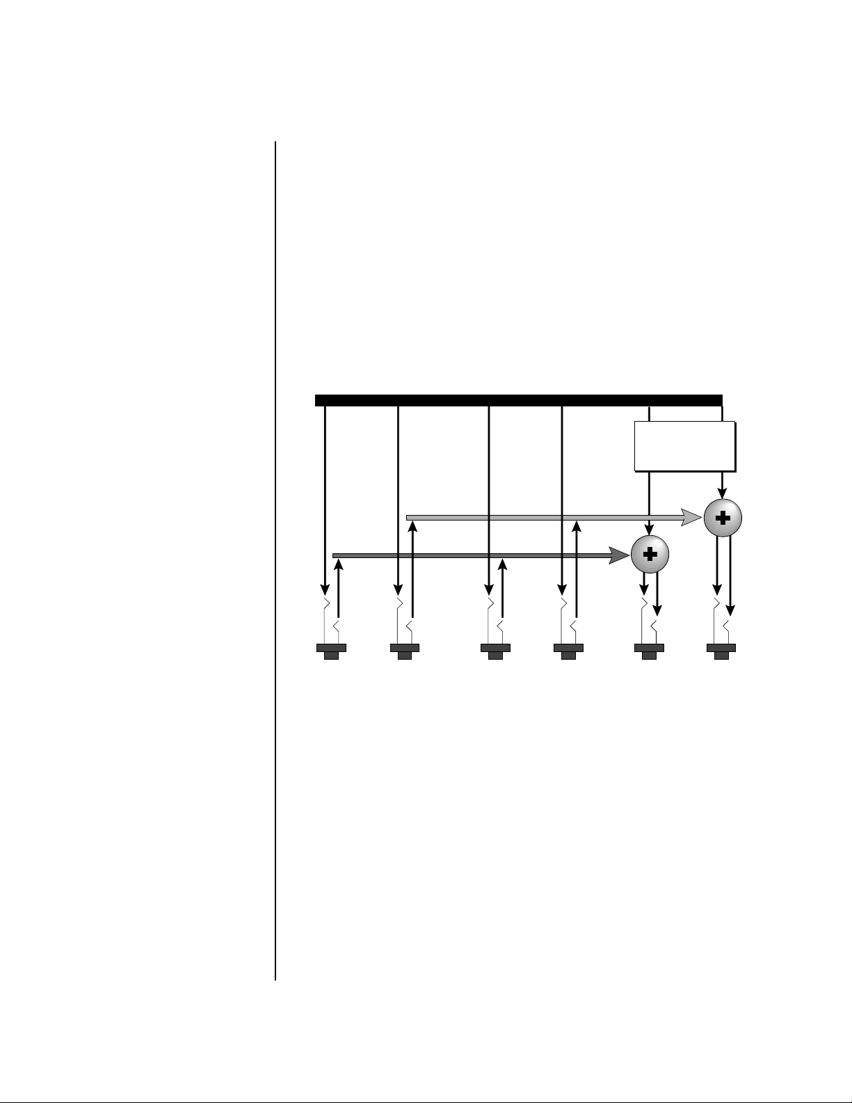
If you insert a stereo plug into one of the Sub Outputs, the ring of the plug
serves as a signal Return which sums into the Main outputs.
Therefore, the Sub 1 and Sub 2 jacks can serve as effect sends and
returns in order to further process selected instruments and then
return them to the main mix.
You can use the Sub 1 and Sub 2 jacks as send/returns in order to further
process selected Virtuoso 2000 presets without using the effects bus on the
mixing board. In a pinch, the effect returns can be used to sum additional
instruments into the main outputs. It’s like having an extra line mixer
when you need more inputs!
Output Section
Effects
Processors
L Bus
R Bus
Tip
Ring
Tip
Ring
Tip
RL
SUB 2
You can use the Sub 1 and Sub 2 jacks as effect returns to the Main Outputs.
Note that the Effects Processors are only routed to the Main Outputs.
Tip
Ring
Ring
RL
SUB 1
RL
MAINS
Power Up! The power switch is located on the right side of the front panel. You can
turn on the Virtuoso 2000 and its MIDI controller in any order. When
power is applied the liquid crystal display will light, indicating that
Virtuoso 2000 is operating. You may have noticed that there is no 110/220
Volt power selector switch on Virtuoso 2000.
Virtuoso 2000 automatically switches itself to the proper line voltage.
Virtuoso 2000 Owner’s Manual 17
Page 26

Setup
Instant Gratification
Instant
Gratification
Playing Demo Sequences
This section presents step-by-step instructions for the most fundamental
operations to get you up and making sounds quickly.
Virtuoso 2000 has several factory demonstration sequences that let you
hear what this incredible machine can do. The actual number of demo
sequences depends on which ROM sounds sets are installed. You can play
these demo sequences by accessing the Demo Sequence page.
DEMO SEQUENCES ORCH1
C
artoon
To Play a Demo Sequence
1. Press and hold the Master and Edit buttons at the same time to enter
the Demo Sequence page. The screen shown above appears.
2. Select a sequence using the data entry control. The Enter LED will be
flashing.
3. Press the Enter button to begin playing the selected sequence. The
screen shown below appears.
PLAYING: Cartoon
Press ENTER to stop
4. Press the Enter button again to stop playing the sequence.
5. When a demo sequence plays to the end, the next demo will automati-
cally begin playing. The screen will display the new demo name.
6. With the sequence stopped, press either the Master, Edit or Multi
button to Exit the demo sequence mode.
Auditioning Presets The front panel audition button allows you to hear any preset in Virtuoso
2000 without even hooking up a MIDI keyboard! When the Audition
button is pressed, the LED next to the button will illuminate and a short
“Riff” (programmed as part of the preset) will play. The Riff is latched on
and plays continuously until the button is pressed again. Presets can be
changed while Audition is latched on.
The top line of the display changes to show the MIDI Bank Select controller
values needed to select the preset being auditioned. This is an extremely
handy feature when sequencing.
18 E-MU Systems
Page 27
Instant Gratification
BankSel 0:00 32:1 User
0
581 wnd:Dyno Flute
To Audition a Preset
1. Select a preset by turning the data entry control while the cursor is
anywhere on the lower line. The preset number field (shown above) is
the normal position of the cursor and pressing the Enter button will
return the cursor to this position.
2. Press the Audition button on the front panel. The Audition LED will
illuminate and a short riff will play the selected preset.
3. Continue to select and audition presets.
4. Press the Audition button again to turn Audition mode off. The LED
will extinguish.
Setup
Selecting and Quick Editing Presets
The first thing you’ll do with the Virtuoso 2000 is select and play the
factory provided presets. Virtuoso 2000 comes standard with 4 banks
containing 128 presets each.
Preset
Location
Channel
Number
Initial
Volume
Setting
Initial
Pan
Setting
C01 Vol127 Pan01R User
000 str: Hall Legato 1
0
Preset
Number
The first four banks are USER locations that can be overwritten and used to
store your own presets. The presets that come stored in the USER presets are
duplicated in banks 0-3 of the “ORCH1” & “ORCH2” ROM banks, so feel
free to overwrite them with your own presets. You won’t be losing
anything.
Bank
Number
Preset
Category
Preset
Name
Virtuoso 2000 Owner’s Manual 19
Page 28
OO
OO
You can select presets
from the Preset Number, Bank
Number, Preset Category or
Preset Name fields.
Setup
Instant Gratification
The ROM Card identifier is shown in the top right of the display. The preset
is identified in the bottom line of the main screen (the screen that appears
when you first power up the unit).
Each bank of 128 presets is identified by a superscripted Bank Number to the
right of the preset number. The bank numbers reset to 0 at the start of each
ROM card you have installed. So with the Virtuoso 2000 ROMs installed,
the USER banks will go from 0-3, then start over from 0-3 for the CMPSR
banks.
To the right of the preset number and bank is the preset Category name
followed by the Preset Name.
To Change the Preset
1. Place the cursor under the first character in the Preset Number field.
This is the “Home” position which is selected instantly when you press
the Home/Enter button. Pressing either of the two cursor buttons
repeatedly also gets you there.
2. Turn the Data Entry Control knob on the front panel to select a new
preset number. If you turn the knob slowly, the presets advance one
number for each “click” of the knob. If you spin the knob quickly, the
numbers advance much faster (more than one number per click).
3. Play the keyboard (or press the Audition button) and listen to the
sounds made by your Virtuoso 2000!
4. TURN THE FOUR KNOBS on the front panel and note how they
change the sound of each preset! The button to the left of the knobs
changes the knob’s function. Don’t worry about ruining the sound, the
values are automatically reset as soon as you select a new preset.
20 E-MU Systems
Bank Organization
USER
USER
USER
USER
ORCH 1
ORCH 1
ORCH 1
}
ORCH 2 Bank 0 128 Presets
The four User Banks can hold 512 custom presets. Feel free to overwrite
these since the factory user presets are duplicated in nonvolatile ROM.
Bank 0
Bank 1
Bank 2
Bank 3
Bank 0
Bank 1
Bank 2
128 Presets
128 Presets
128 Presets
128 Presets
128 Presets
128 Presets
128 Presets
Page 29
Basic Operations
A/E
VOLUME
B/F
C/G
D/H
AUDITION
MULTITISASA
VE/COPY
HOME/ENTER
MIDI
POWER
TONE
ACK
DYNAMIC 1
A-D
E-H
I-L
PRESENCE
DECA
Y/RLS
DYNAMIC 2
SHAPE
MOVEMENT
FX A
IMAGE
TE
FX B
MASTER
EDIT
Control
Button
VOLUME
A-D
E-H
I-L
Volume Control
TONE
ATTTTACK
DYNAMIC 1
A/E
PRESENCE
DECA
DYNAMIC 2
B/F
Y/RLS
SHAPE
MOVEMENT
FX A
C/G
MASTER
AUDITION
Edit
Menu
EDIT
MUL
VE/COPY
Cursor
Controls
HOME/ENTER
Master
Menu
IMAGE
RARATE
FX B
D/H
CO1 A V o l 127 Pan0 1RCROH1
0223str :BaroqueQua tetr
Power
Switch
POWER
MIDI
Display
Headphone
Jack
Realtime
Control Knobs
Audition
Button
Multimode
Button
Save/
Copy
Home/
Enter
Data
Entry
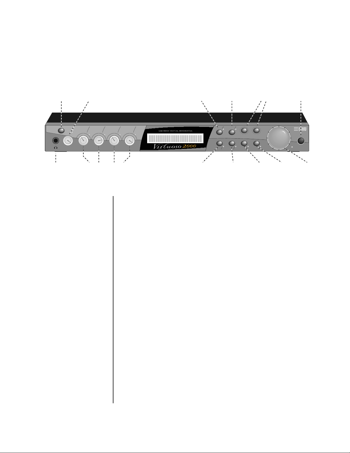
Front Panel The Virtuoso 2000 front panel contains an LCD screen, nine buttons and
four real-time controllers. Functions are grouped logically and the controls
are arranged for ease of use. Precisely because Virtuoso is so simple to use,
you might be tempted to skip this section. If you just can’t help yourself, at
least read the Real-time Controller information beginning page 23. There
are several “power user” features in the interface which make programming
even easier and we wouldn’t want you to miss them.
Volume Control This control is the master volume control for all audio outputs. The Volume
Control does not affect any editing or user interface operations.
Master Button The Master menu contains parameters that affect the entire machine, not
just certain presets. An illuminated LED to the right of the button indicates
that you are in the Master menu.
Edit Button Use the Edit menu when you want to create or modify a preset. An illumi-
nated LED to the right of the button indicates that you are in the Edit
menu.
Control Button The Control button is used to change the function of the Controller knobs
(see the next section). Each time you press the Control button, the Control
Mode toggles to select only one of the three Control Rows. The currently
selected Control Row is indicated by one of the three LEDs to the right of
the row’s label.
Virtuoso 2000 Owner’s Manual 21
Page 30
Basic Operations
Front Panel
Audition Button The Audition button allows you to hear any preset without hooking up a
MIDI keyboard. When the Audition button is pressed, the LED next to the
button will illuminate and a short “Riff” (programmed as part of the preset)
will play. The Riff is latched on and plays continuously until the button is
pressed again. Presets can be changed while Audition is latched on.
OO
OO
See “Bank Select
Commands“ on page 84 for
more information on selecting
banks via MIDI.
The top line of the display changes to show the MIDI Bank Select controller
values needed to select the preset being auditioned. This handy feature lets
you know the exact Bank and Preset number to enter into your sequencer.
MSB
LSB
Left/Right Cursor Buttons
BankSel 0:010 32:0
Preset #
These buttons move the cursor to the next parameter on the display. (The
cursor is a little flashing line underneath one of the parameters in the
display.) Press either cursor button until the cursor is underneath the
desired parameter. The cursor buttons have an auto-repeat feature which
advances the cursor when the button is held continuously.
The cursor can be moved bidirectionally using the Data Entry Control
while either cursor select button is held down (for example, press and hold
the right cursor button and turn the Data Entry Control).
0
020 vln: 16 Leg HP
ORCH1
Multimenu Button The Multimenu button allows you to select a Multi-setup. A Multi-setup is a
group of parameters that you might associate with a particular sequence or
song. It is like a “snapshot” of the current configuration of the module.
There are 128 setups numbered 0-127.
A Multisetup includes all of the following parameters:
• The Preset/Volume/Pan assignments for each of the 32 MIDI channels.
• All Master menu parameters, except for the User Tuning Tables and the
MIDI program change->preset map.
• The Multisetup name.
Save/Copy Button The Save/Copy button is used to save or copy presets and to copy data.
Selected groups of parameters, such as PatchCord settings, can be copied
between Presets and/or between Layers using this menu.
The LED to the right of the button illuminates to indicate that you are in
the Save/Copy menu. The LED also illuminates when any preset parameter
has been changed in the Edit menu (or if the front panel knobs have been
moved with Quick-Edit mode enabled).
22 E-MU Systems
Page 31

Basic Operations
Front Panel Controller Modes
Home/Enter Button The Home/Enter button is dual purpose. In general, this button acts as the
“Home” button. For example, when in an Edit menu, this button snaps the
cursor to the page name field of the current screen. When viewing the
Preset Select screen (we also call it the main screen), this button snaps the
cursor to the preset number field. In these instances, the LED is not used.
Some screens and parameter fields use this button as the “Enter” button. In
these cases, the LED blinks when the cursor is moved to one of these fields
indicating that the module is waiting for your response to initiate the
operation.
Data Entry Control The Data Entry Control is a stepped, variable control switch used to change
parameter values. The wheel increments or decrements the current value
one unit with each click. This control incorporates acceleration, which
advances the value faster if the Data Entry Control is turned quickly.
Controller Knobs Each of the four Real-time Controller knobs has a corresponding LED to its
upper right side. The function of the Real-time Controllers depends on
which row is currently selected and the programming of the preset.
Front Panel
Controller
Modes
The Real-time Controller Knobs serve three purposes:
1. Real-time control of synthesizer parameters
2. “Quick Editing” the initial settings of the real-time controllers
3. “Deep Editing” the parameters
This section describes each of the three uses.
Real-time Control The Real-time controller knobs provide direct control of Virtuoso 2000’s
synthesizer parameters. They are always active when on the Preset Select
(main) screen. They can optionally be used to transmit MIDI controller
messages to other MIDI devices.
The Control button (left of the knobs) changes the function of the real-time
controller knobs. Each time the button is pressed, the Control Mode toggles
to select one of the three Control Row groups. The currently selected
Control Row is indicated by the illuminated LED to the right of the button.
The control knob functions are determined by the selected Control Row.
The three Control Rows generate MIDI data that can control the preset on
the current MIDI channel (the channel showing on the Preset and main
screen. The labels (Tone, Presence, Shape, Image, etc.) printed on these rows
show how the factory ROM presets may be programmed to respond. (The
controls might not conform to the front panel labels depending on the preset.) You
can change the way a preset responds to MIDI A-L messages from the Edit
menu (PatchCords).
Virtuoso 2000 Owner’s Manual 23
Page 32

Basic Operations
Front Panel Controller Modes
There is an LED next to each of the control knobs which illuminates to
indicate that the knob setting has been changed from the value
programmed in the preset (when Quick Edit mode is enabled). If the knob
position is returned to the original setting, the LED is extinguished.
If the “Knobs MIDI Out” parameter in the Master menu (see “Knobs/Riff
MIDI Out” on page 51) is set to “transmit,” the system sends a MIDI
controller message when you turn off the Control knob. The MIDI
controller message is sent on the current MIDI channel (also called the
basic channel) using the controller number assigned in the Master menu
(see “Real-time Controller Assignment” on page 48).
The knobs only generate a message when you move a knob to a new value.
The current value jumps to the new value.
Quick Edit This mode uses the Controller knobs to “Quick-Edit” the currently selected
preset without having to enter the Preset Edit menu. This mode is only
active when on the Preset Select screen and when “Quick-Edit” is enabled in
the Master menu (see “Knob Preset Quick-Edit” on page 50).
__
__
Quick-Edit mode must
be enabled in the Master menu.
Initial controller values can be stored in every preset. When you move a
knob with Quick-Edit enabled, the Initial Controller Value is updated with
the knob’s new value. The knob’s LED lights indicating that the preset value
has been changed. The three Control Rows’ MIDI A-L values are stored in
the corresponding Initial Controller Amount parameter in the Edit menu (see
“Initial Controller Amount” on page 127). The Save/Copy button LED
illuminates to remind you that the preset has been edited. “Quick-Edits”
made to a preset are lost if you select another preset before saving them.
To Quick-Edit a Preset
1. Use the Control Knobs to change the sound of the current preset as
desired.
2. Press the Save/Copy button. The display reads, “Save Preset to.”
3. Press the right cursor button to select the bottom row.
4. Optional: Select a new preset location if you don’t want to overwrite
the current preset, or if the current preset is a ROM preset.
5. Press the Enter button to save the preset.
24 E-MU Systems
Page 33

Basic Operations
Front Panel Controller Modes
Deep Edit Mode When in the Master, or Edit menus, you can use the Controller Knobs to
edit parameters. Using the Controller Knobs is a faster method for entering
data, but the Data Entry Control offers finer precision.
To Enable Deep Edit Mode:
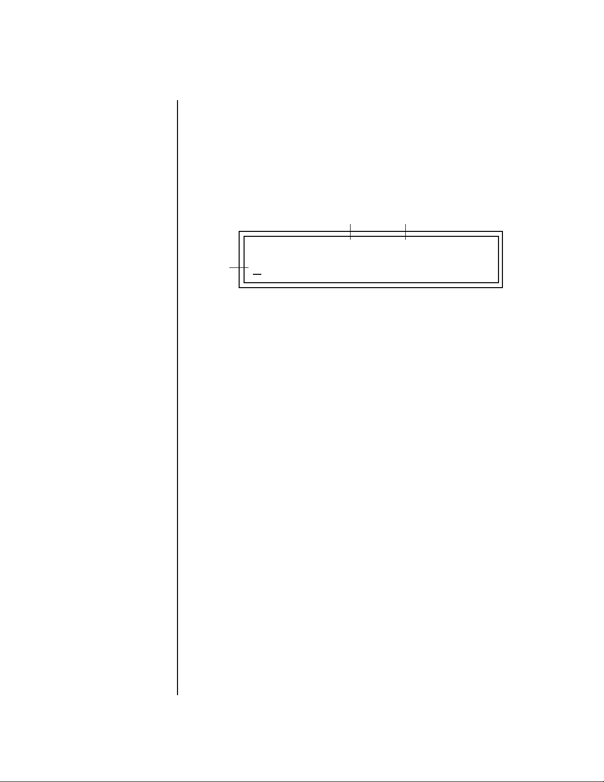
1. Press the Master button and use the Data Entry Control to advance to
the “Knobs Deep Edit” screen as shown in the following illustration.
KNOBS DEEP EDIT
disabled
2. Press either Cursor key to move the cursor to the bottom line in the
display.
3. Use the Data Entry Control to change the value to “enabled.”
4. Press the Master menu button to exit the Master menu.
When you enter any of the Edit menus:
1. The four Controller Knobs are used for editing.
2. All the Controller LEDs are off.
3. All the Control Row LEDS are off.
When you turn a knob, the field value jumps to the current knob value.
You can still use the Data Entry Control for editing by moving the cursor to
the desired field.
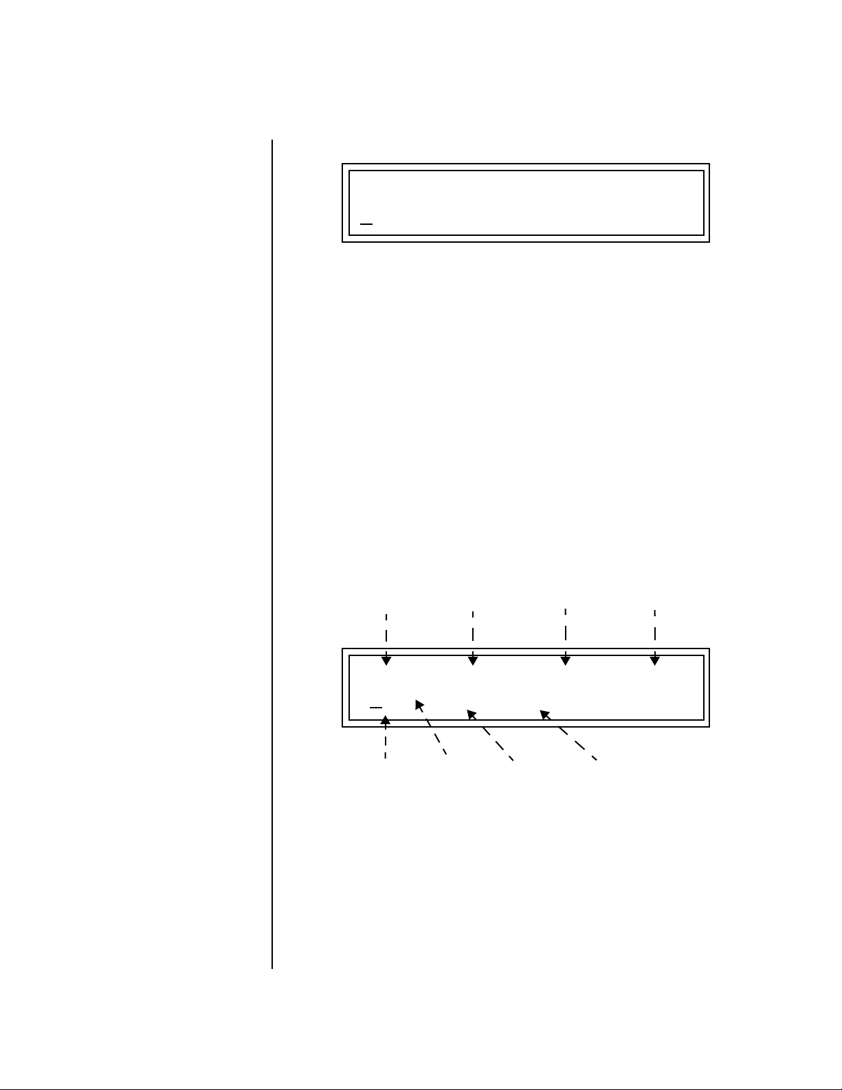
L1
KEY: LO FADE HIGH FADE
A/E/I B/F/J C/G/K D/H/L
To move through menus horizontally, use the Data Entry Control (the
page’s title field is the default cursor position). To move through menus
vertically (preset layers), press the left cursor to get to the layer field, then
change layers with the Data Entry Control.
C-2 000 G8 000
• Use the Data Entry Control to move through menus (horizontally) or
layers (vertically).
• Use the Controller Knobs to change parameter values within each page.
Virtuoso 2000 Owner’s Manual 25
Page 34

Basic Operations
Main Screen
Main Screen The Preset Select screen is Virtuoso 2000’s default screen (also called the
main screen) and is active when you have not selected any of the other
button-activated menus. From this screen you can change or examine the
Preset, Volume, Pan Position and Preset Location for each of the 32 MIDI
channels.
MIDI Channel
ROM or RAM Preset Location
C01A Vol127 Pan01
0020 vln: 16 Leg HP
MIDI Channel Selection
The channel number
shown in the main screen is the
“basic MIDI channel” when in
Omni or Poly modes.
To Change the MIDI Channel
1. Press either cursor button until the cursor is underneath the channel
number. (The cursor is the little flashing line underneath one of the
parameters in the display.)
2. Rotate the Data Entry Control to select a MIDI channel (01A-16A,
01B-16B). As the channel number changes, the display changes to show
the preset, volume, pan and preset location associated with the
displayed channel.
Preset Selection To Change the Preset
1. Press either cursor key until the cursor is underneath the preset number.
(The cursor is a little flashing line underneath one of the parameters in
the display.) As you rotate the Data Entry Control, the preset number
and name changes.
2. The displayed preset is assigned to the displayed MIDI channel. Presets
Bank Contents
0
128 RAM Presets
1
128 RAM Presets
2
128 RAM Presets
USERROM 1
3
128 RAM Presets
0
128 ROM Presets
1
128 ROM Presets
2
128 ROM Presets
are arranged into banks of 128, as shown in the diagram at left.
Bank Number
Preset
Number
C01A Vol127 Pan01
0020 vln: 16 Leg HP
R
R
USER
USER
??
The USER preset banks can
be modified or replaced with
your own sounds.
26 E-MU Systems
Depending on
ROM sets installed
Using the screen above as an example, the superscripted number 0 in the
second line of the display identifies the current bank number.
Page 35
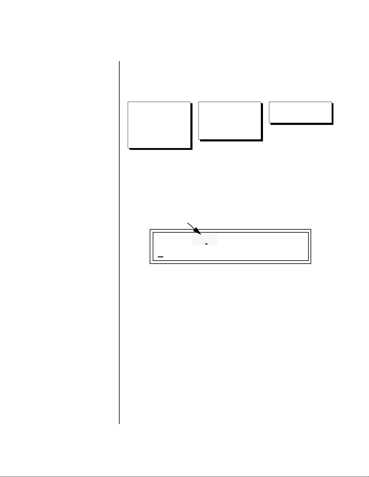
Basic Operations
Main Screen
• Select banks independently of the of the preset number by locating the
cursor on the Bank field and turning the Data Entry Control.
USER
Bank
0
128 User Presets
1
128 User Presets
2
128 User Presets
3
128 User Presets
The Bank numbers start at zero for each ROM sound set installed in Virtuoso 2000.
ORCH1
Bank
0
128 ROM Presets
1
128 ROM Presets
2
128 ROM Presets
ORCH2
Bank
0
128 ROM Presets
Channel Volume Channel Volume sets the volume of the selected MIDI channel in relation
to the other channels. This is the same parameter as MIDI volume control
#7, and changes made over MIDI are shown in the display.
Volume
C01A Vol127 Pan01
R
USER
0020 vln: 16 Leg HP
To Change the Channel Volume
1. Press either cursor key until the cursor is underneath the volume value.
2. Rotate the Data Entry Control to select a volume level. The Channel
Volume range is 000-127.
Virtuoso 2000 Owner’s Manual 27
Page 36

Basic Operations
Main Screen
Channel Pan Channel Pan sets the stereo position of the selected MIDI channel. This
control operates like the balance control on your home stereo system.
Channel Pan is the same parameter as MIDI pan controller #10, and
changes made over MIDI are shown in the display.
Pan Position
C01A Vol127 Pan01
R
USER
0020 vln: 16 Leg HP
Note: Pan settings in the preset ADD algebraically with the Channel Pan
setting. Therefore, if the pan setting in the preset were set to “63
the Channel Pan setting full left would return the sound to the center
position.
To Change the Channel Pan
1. Press either cursor key until the cursor is underneath the pan field.
2. Rotate the Data Entry Control to select a pan value. 64L indicates a hard
left pan, 63R indicates a hard right pan. With a setting of “00,” the
sound is centered in the stereo field.
R,” moving
28 E-MU Systems
Page 37

Basic Operations
Sound Navigator
Sound
Navigator
Sound Navigator allows you to search through preset and instrument
categories to find the type of sound you’re looking for. Each preset and
instrument has a name and a three letter preset category. You can create
your own categories in order to group favorite presets. The preset category
is assigned in the Edit menu (Preset Name). Instrument categories are fixed.
Preset Category When you want to find presets in a particular category, you simply change
the category field in the main screen, then move the cursor to the preset
name field to scroll through all the presets in the selected category.
When the cursor is on the Preset Category field, turning the Data Entry
Control selects different preset categories. The Name Field will change to
show the first preset in each category.
C01 Vol127 Pan00
USER
0020 vln: 16 Leg HP
Preset Category
To Change the Preset Category
1. Press either cursor key repeatedly until the cursor is underneath the
preset category field.
2. Rotate the Data Entry Control to select one of the preset categories.
Preset Categories are displayed in alphabetical order.
Preset Name
To Select a Preset within a Category
1. After selecting a category, move the cursor to the Preset Name field.
2. Rotate the Data Entry Control to scroll through the presets in the
selected category. Note that the preset numbers will no longer change
sequentially.
Instrument Category When the cursor is on the Instrument Category field (Edit menu), turning
the Data Entry Control selects different instrument categories. The Name
Field changes to show the first instrument in each category. Move the
cursor back to the instrument number to select instruments in the selected
category.
L1
INSTRUMENT Rom:ORCH1
0103 wnd: EngHorn p
Virtuoso 2000 Owner’s Manual 29
Page 38

Basic Operations
SCOTTS V
ALLEY CA. U.S.A.
THRU
IN
IN
Multitimbral Operation
Multitimbral
Operation
OO
OO
Save the Multisetup
using the instruction provided in
Chapter 3:Multisetup.
Multitimbral operation means that Virtuoso 2000 can play more than one
sound at the same time. Follow these instructions to access multiple presets
on different MIDI channels simultaneously.
To Set Up Virtuoso 2000 for Multitimbral Operation
1. Set the MIDI mode to “multi mode,” using the MIDI mode function in
the Master menu.
2. Decide which MIDI channels you want the Virtuoso 2000 to receive (32
channels can be used simultaneously). If you are using 16 MIDI
channels or less, just use the “A” MIDI port. Use both MIDI ports if you
need more than 16 MIDI channels. You can turn any unused channels
OFF using the MIDI Enable function in the Master menu.
3. Select the desired preset for each of the MIDI channels you want the
Virtuoso 2000 to receive using the MIDI Channel/Preset selection
screen (see previous instructions).
4. Virtuoso 2000 now responds multitimbrally on each of the MIDI
channels you have specified. The volume and pan position parameters
can be adjusted over MIDI (for each MIDI channel) or using the Cursor
and Data Entry Control in the Preset Select screen.
~
A
IN
B
SCOTTS V
ALLEY CA. U.S.A.
THRU
IN
“A” MIDI
channels 1-16
Channel 01
A
Channel 02
A
Channel 03
A
Channel 16
A
Preset
Volume
Pan
Preset
Volume
Pan
Preset
Volume
Pan
Preset
Volume
Pan
“B” MIDI
channels 1-16
Channel 01
B
Channel 02
B
Channel 03
B
Channel 16
B
Preset
Volume
Pan
Preset
Volume
Pan
Preset
Volume
Pan
Preset
Volume
Pan
Virtuoso 2000 has two MIDI inputs with 16 MIDI channels each. Each of the 32 MIDI
channels can be assigned to play a specific preset with unique volume and pan settings.
30 E-MU Systems
Page 39

Multimenu
Multisetups The Multimenu button allows you to save and restore Multisetups. A Multi-
setup is a group of parameters that you might associate with a particular
sequence or song. It is like a “snapshot” of the current MIDI channel
configuration of the module. There are 64 setups numbered 0-63. All
Multisetups are user programmable.
A Multisetup includes ALL the following parameters:
• Preset/Volume/Pan assignments for each of the 32 MIDI channels.
• Multisetup Name
• ALL MASTER MENU PARAMETERS except…
• MIDI Program Change->Preset map
• User Key Tuning Tables
RESTORE MULTISETUP
0
03 Song Cycle
Multisetups can also be restored (selected) via MIDI Bank and Program
change commands. Select: cc00 = 80, cc32 = 00, (dec) then send a Program
Change command corresponding to the Multisetup you wish to select.
To Enable the Multisetup Menu
Press the Multi button, lighting the LED. The Multisetup screen displays the
menu page most recently selected since powering up Virtuoso 2000. The
cursor appears below the first character of the screen heading on line one.
To Select a New Screen
Press the Home/Enter button or press the Cursor button repeatedly until
the cursor is below the screen title heading. Rotate the Data Entry Control
to select another screen.
Virtuoso 2000 Owner’s Manual 31
Page 40

Multimenu
Multisetups
To Modify a Parameter
Press either Cursor button repeatedly (or hold down the left or right cursor
button while turning the Data Entry Control) until the cursor is below the
desired parameter value. Rotate the Data Entry Control to change the value.
To Return to the Main Screen
Press the Multi button, turning off the LED.
Multichannel Volume
This page allows you to set and view the MIDI volume level for all 32 MIDI
channels. This screen lets you set the initial mix of your MIDI sequence.
The display changes dynamically to reflect any incoming MIDI volume
changes (MIDI continuous controller channel 07).
Select the MIDI channel to be edited using the cursor controls. The selected
MIDI channel and the volume values are shown on the lower line of the
display. The bar graph display shows the relative volume levels for each
MIDI channel.
CH VOL
Selected
MIDI Channel
MIDI Channel Volume
To Adjust the Volume of a particular MIDI channel:
1. Press the Multi menu button lighting the LED. The Multi menu screen
displays the menu page most recently selected since powering up
Virtuoso 2000. The cursor appears below the first black volume bar on
line one.
2. Press the cursor buttons to select the desired MIDI channel. The cursor
moves under the associated bar graph and the selected channel is
displayed on line two.
3. Adjust the volume of the selected channel using the data entry control.
01A: 127
32 E-MU Systems
Page 41

Multimenu
Multisetups
Multichannel Pan This page allows you to set and view the MIDI pan position for all 32 MIDI
channels. Pan sets the left/right balance for each channel, allowing you to
position the sound in stereo space. The display changes dynamically to
reflect any incoming MIDI pan changes (MIDI continuous controller
channel 10).
Select the MIDI channel to be edited using the cursor controls. The selected
MIDI channel and the pan position values are shown on the lower left
display. The graphic display shows the relative pan positions for each MIDI
channel.
CH PAN
Selected
MIDI Channel
MIDI Channel Pan Position
01A: 64
R
To Adjust the Pan Position of a particular MIDI channel:
1. Press the Multi menu button lighting the LED. The Multi menu screen
displays the menu page most recently selected since powering up
Virtuoso 2000. The cursor appears below the first pan position graph on
line one.
2. Press the cursor buttons to select the desired MIDI channel. The cursor
moves under the associated bar graph and the selected channel is
displayed on line two.
3. Adjust the pan position of the selected channel using the data entry
control.
Virtuoso 2000 Owner’s Manual 33
Page 42

Multimenu
Multisetups
Restoring Multisetups
Virtuoso 2000 contains 64 Multisetup locations. These are all User
locations which you can use to store your own Multisetups.
Multisetups can also be restored using a MIDI Bank Select command.
Select: cc00 = 80, cc32 = 00, (dec) then send a Program Change command
corresponding to the Multisetup you wish to select.
RESTORE MULTISETUP
03 Song Cycle
0
To Restore (Select) a Multisetup:
1. Press the Multi menu button lighting the LED. The Multi menu screen
displays the menu page most recently selected since powering up
Virtuoso 2000. The cursor appears below the first character of the screen
heading on line one.
2. Go to the “Restore Multisetup” screen (shown above) using the Data
Entry Control. This is the third screen in the menu.
3. Press either cursor button to move the cursor to the bottom line of the
screen.
4. Now, use the Data Entry Control to select a Multisetup. The Enter LED
will be flashing.
5. Press the Enter button to load the selected Multisetup.
34 E-MU Systems
To Save a Multisetup:
1. Set the Preset, Volume, Pan settings the way you want them for all 32
channels. Set the Master menu parameters the way you want them.
2. Press the Multi menu button lighting the LED.
3. If you wish to Name your new Multisetup continue on, otherwise skip
to step 8.
4. Scroll to the “Setup Name” screen (shown below) using the Data Entry
Control.
SETUP NAME
020
User Setup 23
5. Press either cursor button to move the cursor to the bottom line of the
screen.
Page 43

Multimenu
Multisetups
6. Scroll to the “Save Multisetup” screen (shown below) using the Data
Entry Control.
SAVE MULTISETUP to
020
Destination Multisetup
7. Press either cursor button to move the cursor to the bottom line of the
screen.
8. Now, use the Data Entry Control to select the destination location. The
Enter LED will be flashing.
9. Press the Enter button to save the Multisetup.
Virtuoso 2000 Owner’s Manual 35
Page 44

Multimenu
Multitimbral Sequencing
Multitimbral
Sequencing
“Multitimbral” means that Virtuoso 2000 can play multiple sounds at the
same time. For a multitimbral sequence to play back correctly, the proper
preset must be selected for each MIDI channel. This could be done by
inserting preset changes into each track of your sequence before the
sequence starts. Virtuoso 2000 also provides another way to store this “presequence setup” using the Multisetup menu.
Using Multisetups, you’ll set up the preset, volume and pan settings for
each MIDI channel as you build your sequence, then save the Multisetup
when it’s the way you want it. Sending one preset change command before
the sequence starts selects the Multisetup and MIDI settings for all 32
channels.
To Set up Virtuoso 2000 for Multitimbral Operation
1. Set the MIDI mode to “multi mode,” using the MIDI mode function in
the Master menu.
2. Decide which MIDI channels you want Virtuoso 2000 to receive (32
channels can be used simultaneously). If you are using 16 MIDI
channels or less, just use one of the MIDI ports. Use both MIDI ports if
you need more than 16 MIDI channels. You can turn any unused
channels OFF using the MIDI Enable function in the Master menu.
3. Select the desired preset for each of the MIDI channels you want the
Virtuoso 2000 to receive using the MIDI Channel/Preset selection
screen. You can also set the initial Volume and Pan settings for each
channel.
36 E-MU Systems
1. Select Channel
2. Select Preset
4. Virtuoso 2000 now responds multitimbrally on each of the MIDI
channels you have specified. The volume and pan position parameters
can be adjusted dynamically over MIDI (during the sequence).
5. Save the Multisetup.
To Link a Multisetup with your Sequence
1. Insert a MIDI bank and program change in the lead-in measure of your
sequence to select the proper Multisetup before the sequence starts.
2. The Multisetup will now be selected before the sequence starts.
C01 Vol127 Pan00
0
020 vln: 16 Leg HP
R
USER
Page 45

Master Menu
The Master menu contains functions that affect the overall operation of
Virtuoso 2000. For example, changing the Master Tune parameter changes
the tuning of all the presets, not just the one currently displayed.
To enable the Master menu
Press the Master button, lighting the LED. The Master Menu screen displays
the menu page most recently selected since powering up Virtuoso 2000.
The cursor appears below the first character of the screen heading on line
one.
__
__
Warning: Master Menu
changes are automatically
saved when you exit the
module. If the power is turned
off before you exit the module
any changes you have made will
be lost.
To select a new screen
Press the Home/Enter button or press the Cursor button repeatedly until
the cursor is below the screen title heading. Rotate the Data Entry Control
to select another screen.
To modify a parameter
Press either Cursor button repeatedly (or hold down the right cursor button
while turning the Data Entry Control) until the cursor is below the desired
parameter value. Rotate the Data Entry Control to change the value.
To return to the main screen
Press the Master button, turning off the LED.
Virtuoso 2000 Owner’s Manual 37
Page 46
Master Menu
Defining Master Parameters
Defining
Master
Master setup parameters affect overall performance, range, and global
effects. This section describes the Master parameters and how to define
them.
Parameters
Transpose/Tune The Transpose parameter transposes the key of all presets, in semitone
intervals. The transpose range is ± 24 semitones.
Master Tune adjusts the fine tuning of all presets so that you can tune
Virtuoso 2000 to other instruments. The master tuning range is ± 1
semitone in 1/64th semitone increments (1.56 cents). A master tune setting
of “+00” indicates that Virtuoso 2000 is perfectly tuned to concert pitch
(A=440 Hz).
MASTER TRANSPOSE TUNE
+00 semitones +00
Bend Range The Bend Range parameter sets the range of the pitch wheel. This affects
only presets that have their individual Pitch Bend range (defined in the Edit
menu) set to Master. The maximum pitch bend range is ±12 semitones or
one octave in each direction.
38 E-MU Systems
MASTER BEND RANGE
+/- 7 semitones
Page 47

Master Menu
Defining Master Parameters
Velocity Curve You can modify incoming velocity data by a velocity curve in order to
provide different types of dynamics in response to your playing, or to better
adapt to a MIDI controller. The Master Velocity Curve page lets you select
one of thirteen master velocity curves or to leave the data unaltered
(linear).
MASTER VELOCITY CURVE
13
120
100
80
60
40
20
Result Velocity
Linear
0
20
0
40
Played Velocity
120
100
Curve 9
80
60
40
20
Result Velocity
0
20
0
40
Played Velocity
120
100
Curve 2
80
60
40
20
Result Velocity
0
20
0
100
120
80
60
40
100
120
80
60
Played Velocity
120
100
80
60
40
20
Result Velocity
0
20
0
100
120
80
60
40
60
Curve 13
100
80
120
Played Velocity
For a complete list of all available velocity curves, see “Velocity Curves” on
page 178 of the Appendix.
Virtuoso 2000 Owner’s Manual 39
Page 48

Master Menu
Defining Master Parameters
Mix Output The Mix Output parameter allows you to override the routing assignments
made in each preset and instead assign the outputs according to MIDI
channel. For each of the 32 MIDI channels, you can select Send 1-4, or
Preset. When Preset is selected, the output assignment defined in the Preset
Edit menu is used.
MIX OUTPUT
channel 16A: Send2->main
Indicates that the dry signal is
routed to the Main output jacks.
The Output Routing field (pointed to by the arrow) reflects the true
routing of Send 2 or Send 3 to either:
1) the effects processor input or… 2) the rear panel submix jacks.
Since the Sub 1 output is NOT being used, the signal is routed through the
effects processors, then on to the main outputs. If a plug were inserted into
one of the Sub 1 jacks the destination field would read “Sub1” and the dry
signal would be routed directly to the Sub 1 outputs on the back panel.
Send Routings
Send 1 - Main Outputs
Send 2 - Subout 1 or Main Outs
Send 3 - Subout 2 or Main Outs
Send 4 - Main Outputs
MIX OUTPUT
channel 15A: use preset
The Sends function as effect processor inputs (effect sends). Send 2 and
Send 3 are also used to route sounds to the Sub 1 and 2 outputs on the back
panel. When a plug is inserted into the associated Submix jack on the back
panel, the Dry portion of the Send is disconnected from the effects
processor and the signal is routed directly to the output jack. The actual
output routing is shown in parentheses in the display. If you don’t want
the wet portion of the signal in the main mix, turn down the Send Level.
The entire Send is disconnected from the Effects Processors even if only one plug is
inserted into the Submix jack.
The four Effect Sends allow you to get the most out of the two effect
processors. For example, with Effect B set to an echo algorithm, you could
route one MIDI channel to Send 3 and set the effect amount to 80%.
Another MIDI channel could be routed to Send 4 with an effect amount of
only 5%. This is almost like having two different effects!
The Mix Output function is also useful when sequencing since it lets you
route specific MIDI channels (and thus sequencer tracks) to specific Sub
outputs (on the back panel) where there they can be processed with EQ or
other outboard effects.
40 E-MU Systems
Page 49

Defining Master Parameters
OUTPUT SECTION
& EFFECTS PROCESSORS
Master Menu
MIDI Channel 1A
MIDI Channel 2A
MIDI Channel 3A
MIDI Channel 16A
MIDI CHANNEL
MIDI Channel 1B
MIDI Channel 2B
MIDI Channel 3B
Preset
Preset
N
D
N
D
N
D
FX Sends
Send 1 15%
Send 2 10%
Send 3 0%
Send 4 0%
S
E
Hall 1
Effect
A
B➟A
M
A
I
1
FX Sends
Send 1 0%
Send 2 0%
Send 3 20%
Send 4 15%
S
E
Chorus
Effect
B
Jack
Detect
N
S
U
B
2
S
E
Jack
Detect
1
S
U
B
3
2
MIDI Channel 16B
MIDI CHANNEL
S
E
N
D
4
Sends 2 and 3 can be routed to the effects processors or to rear panel submix jacks.
When a plug is inserted into a Submix jack, the dry portion of the Send is disconnected
from the effects processor and is routed directly to the Submix output jacks.
Virtuoso 2000 Owner’s Manual 41
Page 50

Master Menu
Master Effects
Master Effects The digital effect processors can be programmed as part of the preset (using
the Edit menu) so that effects will change along with the preset. However,
there are only two effect processors, and so you cannot have a different
effect on each preset when in Multi mode.
The Master Effects settings assign the effect processors “globally” for all
presets to provide a way to use the effects in Multi mode. Detailed information is presented in the Effects chapter (see Effects on page 145).
Effects Mode The FX Mode page enables or bypasses the effects. When the FX Mode is set
to “bypass,” the effects are turned off on a global scale. This includes Effects
programmed in the preset.
FX MODE
enabled
Effects Multi Mode Control
The routing scheme for the two stereo effects processors provides a lot of
versatility. When in multi mode, you can “use master settings” which
applies the Master menu effects settings to all 32 MIDI channels.
FX MULTIMODE CONTROL
use master settings
If you want more control, you can use the “channel” setting which applies
the effects settings of the preset on a specified channel to all the other
channels. Changing the preset on the specified channel changes the effect.
FX MULTIMODE CONTROL
preset on channel 1A
If you are in Omni or Poly modes this parameter is disabled and the
message in parentheses explains that Proteus is currently in Omni mode.
42 E-MU Systems
FX MULTIMODE CONTROL
(using Omni mode)
Page 51

Master Menu
Master Effects
Master FXA Algorithm
This function selects the type of effect used for the “A” effect. The following
effect types are available.
MASTER FXA ALGORITHM
Room 1
A Effect Types
1. Room 1
2. Room 2
3. Room 3
4. Hall 1
5. Hall 2
6. Plate
7. Delay
8. Panning Delay
9. Multitap 1
10. Multitap Pan
11. 3 Tap
12. 3 Tap Pan
13. Soft Room
14. Warm Room
15. Perfect Room
16. Tiled Room
17. Hard Plate
18. Warm Hall
19. Spacious Hall
20. Bright Hall
21. Bright Hall Pan
22. Bright Plate
23. BBall Court
24. Gymnasium
25. Cavern
26. Concert 9
27. Concert 10 Pan
28. Reverse Gate
29. Gate 2
30. Gate Pan
31. Concert 11
32. Medium Concert
33. Large Concert
34. Large Concert Pan
35. Canyon
36. DelayVerb 1
37. DelayVerb 2
38. DelayVerb 3
39. DelayVerb 4 Pan
40. DelayVerb 5 Pan
41. DelayVerb 6
42. DelayVerb 7
43. DelayVerb 8
44. DelayVerb 9
Virtuoso 2000 Owner’s Manual 43
Page 52

Master Menu
Master Effects
FXA Parameters: Decay/HF Damping FxB -> FxA
This page lets you define the parameters of the selected Effects algorithm.
Use this page to setup the effect decay, high frequency damping amount
and to route “B” effects through the “A” effects. See “Effect Parameters” on
page 147 for more details.
FXA DECAY HFDAMP FxB>FxA
040 096 001
FXA Send Amounts These parameters set the effects amounts for each of the four stereo effects
busses. See “Master Effects” on page 150 for detailed information.
FXA SEND AMOUNTS 1:100%
2: 50% 3: 10% 4: 0%
Master FXB Algorithm
This parameter selects the type of effect used for the “B” effect. The
following effect types are available.
MASTER FXB ALGORITHM
Chorus 1
44 E-MU Systems
Page 53

B Effect Types
Master Menu
Master Effects
FXB Parameters: Feedback/LFO Rate Delay Time
1. Chorus 1
2. Chorus 2
3. Chorus 3
4. Chorus 4
5. Chorus 5
6. Doubling
7. Slapback
8. Flange 1
9. Flange 2
10. Flange 3
11. Flange 4
12. Flange 5
13. Flange 6
14. Flange 7
15. Big Chorus
16. Symphonic
17. Ensemble
18. Delay
19. Delay Stereo
20. Delay Stereo 2
21. Panning Delay
22. Delay Chorus
23. Pan Delay Chorus 1
24. Pan Delay Chorus 2
25. Dual Tap 1/3
26. Dual Tap 1/4
27. Vibrato
28. Distortion 1
29. Distortion 2
30. Distorted Flange
31. Distorted Chorus
32. Distorted Double
The FXB parameters setup the characteristics of the effect. Use this page to
define the feedback amount, the LFO rate and delay amount for the
selected type “B” effect. See “Effect Parameters” on page 147 for details.
FXB FEEDBK LFORATE DELAY
000 003 0
FXB Send Amounts These parameters set the effects amounts for each of the four stereo effects
busses. See the Effects chapter for detailed information.
FXB SEND AMOUNTS 1:100%
2: 50% 3: 10% 4: 0%
Virtuoso 2000 Owner’s Manual 45
Page 54

Master Menu
MIDI Parameters
MIDI
Parameters
MIDI parameters control how the Virtuoso 2000 sends and receives MIDI
data.
MIDI Mode MIDI Mode selects one of the three MIDI modes: Omni, Poly or Multi
mode.
MIDI MODE CHANGE
omni ignored
The MIDI Mode Change parameter specifies whether mode changes made
through an external MIDI controller are accepted or ignored.
The MIDI modes are as follows:
Omni
Responds to note information on all MIDI channels and plays the preset
currently displayed in the main screen.
Poly
Responds only to note information received on the currently selected MIDI
channel (on the preset selection screen) and plays that channel’s associated
preset.
Multi
Responds to data on any combination of MIDI channels and plays the
specific preset associated with each of the MIDI channels. You must select
multi mode for multitimbral operation.
MIDI SysEx ID This page defines the MIDI system exclusive (SysEx) device ID number. The
SysEx ID lets an external programming unit to distinguish between
multiple Virtuoso 2000 units connected to the same preset editor. In this
case each unit must have a unique SysEx ID number.
__
__
WARNING: When
transferring SysEx data from one
Virtuoso 2000 to another, the ID
numbers of both units must be
the same.
46 E-MU Systems
MIDI SYSEX ID
000
Page 55

Master Menu
MIDI Parameters
MIDI Enable MIDI Enable lets you turn each MIDI channel on and off independently
when in Multi mode. This feature is helpful when you have other devices
connected to the same MIDI line and do not want the Virtuoso 2000 unit
to respond to the MIDI channels reserved for the other devices.
MIDI ENABLE
channel 01A: On
Because the MIDI Enable function only makes sense if you are in Multi
mode, Virtuoso 2000 disables this feature when in Omni or Poly mode.
MIDI Program Change -> Preset
The Program->Preset
Change only works for program
changes received in Bank 0.
In Multi
Mode
In Omni
Mode
MIDI ENABLE
channel 16B: On
MIDI ENABLE
(using Omni mode)
You can also remap incoming MIDI program changes to a different
numbered preset. This is a handy feature when your master keyboard
cannot send a bank change or you want to reorder preset numbers. Any
preset can be mapped to any incoming MIDI program change number.
For example, you could set up the Program -> Preset map to call up preset
#12 whenever Virtuoso 2000 receives MIDI program change #26.
The four fields shown below are editable.
MIDI PROG CHNG -> PRESET
000 User 000
0
Incoming Program
Change in Bank 0
ROM Bank
Program No. Bank No.
Virtuoso 2000 Owner’s Manual 47
Page 56

OO
OO
Programs and presets
are the same thing. “Preset” is
the E-mu term for MIDI
Program.
Selected
Program
0 1 2 3 4 5 6 7 8 9
0000000000
00 01 02 03 04 05 06 07 08 09
201000 0 0
44 91 50 01 15 88 99 78 32 88
10
10002000 02
34 73 106 55 43 75 120 121 100
20
0000000000
30 31 32 33 34 35 36 37 38 39
30
0000000000
40 41 42 43 44 45 46 47 48 49
40
0000000000
50 51 52 53 54 55 56 57 58 59
50
0000000000
60 61 62 63 64 65 66 67 68 69
60
0000000000
70 71 72 73 74 75 76 77 78 79
70
0000000000
80
80 81 82 83 84 85 86 87 88 89
0000000000
90
90 91 92 93 94 95 96 97 98 99
100
110
120
0000000000
100 101 102 103 104 105 106 107 108 109
0000000000
110 111 112 113 114 115 116 117 118 119
00000000
120 121 122 123 124 125 126 127
12
Master Menu
MIDI Parameters
41
Mapped
Program
Receive Program Change
Real-time Controller Assignment
In this chart, program changes 10-29 have been remapped to new preset numbers. All
other presets are selected normally.
Use this function to instruct the Virtuoso 2000 to utilize or ignore
incoming MIDI preset changes or Bank Select commands for each channel.
Use the cursor buttons to select the channel number field, then use the
Data Entry Control to select a channel number. Use the cursor button again
to select the On/Off field and the Data Entry Control to change the value.
RECEIVE PROGRAM CHANGE
channel 01A : on
Use these three pages to assign twelve real-time control sources. Each MIDI
Controller is assigned a letter (A - L). The front panel Controller Knobs and
twelve MIDI controller numbers share the A-L controller routings. These
screens let you select which MIDI real-time controllers numbers will be
received (from 1 to 31 and from 64 to 119) and which controller
numbers will be transmitted over MIDI if the front panel controls are
turned.The PatchCord routing and amount in the Edit menu determine
what effect the controller has on each preset. Real-time controllers are
shown in the PatchCord menu as MIDI A through MIDI L.
48 E-MU Systems
Page 57

OO
2
3
4
5
OO
Tip: Virtuoso 2000
factory presets have certain
synth parameters assigned to
each controller letter and so
these are “Global” controller
assignments.
For example, assigning a MIDI
controller to “A” in this screen
would let you control filter Fc for
all the factory presets. See
“Front Panel Knob Functions” on
page 167.
Master Menu
MIDI Parameters
The Real-time Controller assignment also specifies which controller
numbers are transmitted when the “Knobs MIDI Out” is enabled (see
“Knobs/Riff MIDI Out” on page 51).
REALTIME CONTROLLER #
A: 21 B: 22 C: 23 D: 24
REALTIME CONTROLLER #
E: 25 F: 26 G: 27 H: 28
REALTIME CONTROLLER #
MIDI Footswitch Assign
I: 80 J: 81 K: 91 L: 93
Note: Controllers 7 and 10 are already assigned to Volume and Pan for each
MIDI channel. Controllers 91 & 93 are the standard controller numbers for
reverb and chorus send amounts.
Following are a few of the standardized MIDI Controller numbers as
defined by the MIDI manufacturers association. The controllers shown in
Bold are automatically routed to the destination (volume & pan) or have
their own PatchCord source. Others, such as Portamento Time, can be
routed using a PatchCord to have the desired effect.
1 - Modulation Wheel
- Breath Controller
- Old DX7 Aftertouch
- Foot Pedal
- Portamento Time
6 - Data Entry
Like the MIDI Controllers, you can assign three MIDI footswitches to MIDI
footswitch numbers. Footswitches numbers are from 64-79. Destinations
for the footswitch controllers are programmed in the PatchCord section of
the Edit menu.
7 - Volume
8 - Balance
9 - Undefined
10 - Pan
11 - Expression
FOOTSWITCH CONTROLLER #
1: 64 2: 65 3: 66
Virtuoso 2000 Owner’s Manual 49
Page 58

MIDI Parameters
Following are a few of the standardized MIDI Switch numbers.
Master Menu
64 - Sustain Switch (on/off)
65 - Portamento (on/off)
66 - Sostenuto (on/off)
67 - Soft Pedal (on/off)
69 - Hold Pedal 2 (on/off)
Tempo Controller This function allows a MIDI controller to change the Master Tempo. The
Global Tempo is used for the clock divisor PatchCords, tempo-based
envelopes and synced LFOs. You can assign any controller number from
0-31, mono key pressure, or the pitch wheel to change the Global Tempo.
A different controller can be used to change the tempo up or down. The
Pitch Wheel can be assigned to both the up and down parameters to vary
the tempo up and down from a single controller. If any other controller is
assigned to both the up and down parameters, Virtuoso 2000 redefines the
center of the controller’s range as zero.
MIDI Controller values are added to the Base Tempo with an offset range of
±64. When the controller is set to “off” the tempo returns to its original
setting. This control has no effect when using an external clock.
TEMPO CONTROLLER# CHAN
Knob Preset Quick-Edit
Quick Edit does not work
while in the Edit menu with
“Knobs Deep Edit” enabled.
50 E-MU Systems
Up: 03 Down: 09 16A
“Quick-Edit” changes the initial controller setting in the preset whenever
you move a Control Knob. This parameter selects whether or not the front
panel Controller Knobs are used to Quick-Edit the currently selected preset.
See “Controller Knobs” on page 23 in the Operations chapter for more
details.
KNOBS PRESET QUICK-EDIT
disabled
Page 59

Master Menu
MIDI Parameters
Knobs Deep Edit
This parameter specifies whether or not the front panel controller knobs
can be used to edit parameter values in the Master or Edit menus. This is
called “Deep-Editing.” With Knob Deep Edit disabled, the front panel
controller knobs retain their function as real-time controllers even when in
the Master or Edit modes.
KNOBS DEEP EDIT
disabled
Knobs/Riff MIDI Out This function allows you to select whether or not MIDI controller data is
transmitted when you turn the front panel Controller knobs. The knobs
transmit on the controller numbers defined by the Real-time Controller
Assign parameter (see page 48). This function also enables or disables transmission of Riff note data over MIDI when the Audition button is pressed.
If Deep Edit is enabled, “Knobs MIDI Out” does not work while in any of
the editing menus (Master, Edit, Save/Copy).
Preset Edit All Layers Enable
KNOBS/RIFF MIDI OUT
don’t transmit
This function allows you to turn the Edit All Layers feature on or off. “Edit
All Layers” is an Edit menu feature which allows you to select all layers (A)
in order to edit all four layers simultaneously. Because this feature can be
confusing to the beginning programmer, it can be disabled here in the
Master menu. Check this feature out when you’re ready. It’s great!
PRESET EDIT ALL LAYERS
enabled
Virtuoso 2000 Owner’s Manual 51
Page 60
Master Menu
MIDI Parameters
Front Panel Knob Calibration
This function calibrates the minimum and maximum values for the five
front panel knobs. The controls should be calibrated periodically in order to
compensate for normal wear and tear on the controls themselves or if the
controls behave strangely. Before calibration, it’s usually a good idea to let
the unit warm up for about half an hour to ensure you have the maximum
range on all the front panel controls.
To Calibrate the Front Panel Control Knobs
1. Press the Master menu button and advance to the Calibrate Knobs page.
CALIBRATE KNOBS
Start
2. Press the Enter button to begin the calibration process. The following
screen appears.
Turn all knobs to MIN
Press Enter when ready
3. Turn all knobs to their minimum value (which is pegged in the counter-
clockwise direction), then press the Enter button. The screen briefly
flashes, “Reading Values…,” then displays:
Turn all knobs to MAX
Press Enter when ready
4. Turn all knobs to their maximum value (pegged in the clockwise
position), then press the Enter button. The display shows, “Reading
Values… Done.” Calibration is complete.
52 E-MU Systems
Page 61

Master Menu
MIDI Parameters
MIDI SysEx Packet Delay
Send MIDI System Exclusive Data
Sometimes errors occur if the computer or sequencer to which you are
sending MIDI SysEx data is faster or slower than the Virtuoso 2000. The
MIDI SysEx Packet Delay command lets you specify the amount of delay
between MIDI SysEx packets so the input buffer of your computer does not
overflow, causing an error. The value range is from 0 through 8000 milliseconds. A delay value of zero allows full speed MIDI transfer. If you are
experiencing data transmission errors, try increasing the delay value until
the problem disappears.
MIDI SYSEX PACKET DELAY
300 milliseconds
This command transmits MIDI System Exclusive (SysEx) data to the MIDI
Out port of Virtuoso 2000. The MIDI data can be sent to a computer,
sequencer or to another Virtuoso 2000. When transferring data between
two Virtuoso 2000s be sure both units have the same SysEx ID number! See
“MIDI SysEx ID” on page 46 to learn how to change the SysEx ID.
Using the cursor key and the Data Entry Control, select the type of MIDI
data you want to transmit. Following are descriptions of the types of MIDI
data that can be transmitted.
OO
OO
The Preset, Volume,
and Pan information for all 32
channels is included when the
Multi mode Map settings are
transmitted or received.
Current Multisetup
Transmits all parameters in the Master menu except Tuning Tables,
Program/Preset Map and Viewing Angle.
Program /Preset Map
Transmits the MIDI Program -> Preset Map.
All User Tuning Tables
Transmits all 12 User Tuning Tables.
Multimode Map
Transmits the following parameters:
• Multimode Basic Channel
• Multimode Effects Control Channel
• Multimode Tempo Control Channel
and for each MIDI Channel…
• Preset, Volume, & Pan
• Mix Output
• Multimode Channel Enable
• Multimode Bank Map
• Multimode Receive Program Change
Virtuoso 2000 Owner’s Manual 53
Page 62

__
__
WARNING: When
transferring SysEx data from one
Virtuoso 2000 to another, the ID
numbers of both units must
match.
Master Menu
MIDI Parameters
Bank 0 User Presets
Transmits all the user defined presets in Bank 0.
Bank 1 User Presets
Transmits all the user defined presets in Bank 1.
Bank 2 User Presets
Transmits all the user defined presets in Bank 2.
Bank 3 User Presets
Transmits all the user defined presets in Bank 3.
Any Individual Preset
Transmits only the selected preset.
The Enter LED will be flashing. Press the Enter button to confirm the
operation. To receive MIDI data, simply send the MIDI data into Virtuoso
2000 from another Proteus or from a computer/sequencer.
SEND MIDI SYSEX DATA
bank 1 user presets
To Record MIDI SysEx Data into a Sequencer:
1. Setup the sequencer to receive system exclusive data.
2. Place the sequencer into record mode, then Send MIDI Data.
To Receive MIDI SysEx Data from a Sequencer:
Simply play back the sequence into Virtuoso 2000.
54 E-MU Systems
Page 63

Master Menu
MIDI Parameters
User Key Tuning User Key Tuning lets you create and modify 12 user definable tuning tables.
The initial frequency of every key can be individually tuned, facilitating the
creation of alternate or microtonal scales.
Using the cursor keys and the Data Entry Control, select the user table
number, the key name, the coarse tuning and the fine tuning. The key
name is variable from C-2 to G8. Coarse Tuning is variable from 0 to 127
semitones. The fine tuning is variable from 00 to 63 in increments of 1/64
of a semitone (approx. 1.56 cents). For each preset, the specific tuning table
is selected in the Edit menu.
OO
OO
The user key tuning can
be used to tune individual
percussion instruments.
USER KEY TUNING Table:1
Key: C1 Crs: 036 Fine: 00
Output Format The Output Format parameter sets the digital audio output format. The
available formats are S/PDIF, and AES pro. If you are using the digital
output, choose either S/PDIF or AES pro to match the format of the
receiving device.
OUTPUT FORMAT
S/PDIF
The Virtuoso 2000 contains a S/PDIF digital output. The diagram below
shows how an adapter cable for AES pro should be wired.
__
__
DON’T CHEAP OUT!
Always use high quality cable for
digital audio connections.
N.C.
To AES
Device
12
+
3
-
Shield
Pin
RCA
From
Proteus 2000
Digital OUT
If you use an adapter cable to connect the S/PDIF digital audio output to AES gear, make
sure to use high quality, low capacitance cable.
Virtuoso 2000 Owner’s Manual 55
Page 64

Master Menu
MIDI Parameters
Base Tempo Virtuoso 2000 contains an internal master clock which can be used to:
synchronize the LFOs when in Tempo-based mode, control the times of
Tempo-based envelopes or used as a modulation source in the PatchCords
section. There are two tempo values shown in the display.
• Base Tempo - The base tempo is the value to which the MIDI controller
specified in the Tempo Controller screen will be applied. (See “Tempo
Controller” on page 50.)
• Current Tempo - The current tempo is equal to the base tempo modu-
lated by the MIDI controller specified in the Tempo Controller screen. If
no MIDI Tempo controller message has been received since the last Base
Tempo change, the Current Tempo will be equal to the Base Tempo.
Current Tempo is NOT displayed when the Base Tempo is set to “MIDI
Clock”.
To Change the Master Tempo:
1. Move the cursor to the lower line of the display.
2. Adjust the Base Tempo using the Data Entry Control.
Screen Viewing Angle
BASE TEMPO
1
20 bpm (current: 182)
The Master Tempo values range from 1 through 300 beats per minute
(BPM) or you can select “use MIDI clock” to use an external MIDI clock
source.
This function changes the viewing angle of the display so that you can read
it easily from either above or below the unit. The angle is adjustable from
+7 to -8. Positive values will make the display easier to read when viewed
from above. Negative values make the display easier to read from below.
VIEWING ANGLE
+0
56 E-MU Systems
Page 65

Programming Basics
This chapter explains how Virtuoso 2000 sounds are constructed and
contains important background information on how to create your own
custom presets.
Your initial involvement with Virtuoso 2000 will most likely be using the
existing presets and selecting MIDI channels. While the factory presets are
very good, there are some things you will probably want to change
eventually, perhaps the LFO speed, the filter frequency or the attack time.
You may also want to make your own custom presets using complex
modulation routings. There are 512 user locations (USER Banks 0-3)
available to store your own creations or edited factory presets. Best of all,
it’s easy to edit or create new presets using the Edit menu.
Each preset can consist of up to four instrument layers. Each of the four
layers can be placed anywhere on the keyboard and can be crossfaded or
switched according to key position, velocity, or by using a real-time control
such as a wheel, slider, pedal, LFO or envelope generator. A preset can also
be “linked” with up to 2 more presets creating additional layering or splits.
Virtuoso 2000 has an extensive modulation implementation using two
multi-wave LFO’s (Low Frequency Oscillators), three multi-stage envelope
generators per layer and the ability to respond to multiple MIDI controllers.
You can simultaneously route any combination of these control sources to
multiple destinations.
Virtuoso 2000 Owner’s Manual 57
Page 66

Programming Basics
Modulation
Modulation To modulate means to dynamically change a parameter, whether it be the
volume (amplitude modulation), the pitch (frequency modulation), and so
on. Turning the volume control on your home stereo rapidly back and
forth is an example of amplitude modulation. To modulate something we
need a modulation source and a modulation destination. In this case, the
source is your hand turning the knob, and the destination is the volume
control. If we had a device that could turn the volume control automatically, we would call that device a modulation source.
Turning the volume control back and forth on your home stereo is an example of
Amplitude Modulation.
Virtuoso 2000 is designed so that each of the variable parameters, such as
the volume, has an initial setting which is changed by a modulation source.
Therefore in the case of volume, we have an initial volume that we can
change or modulate with a modulation source.
Two main kinds of modulation sources on Virtuoso 2000 are Envelope
Generators and Low Frequency Oscillators. In the example above, an envelope
generator could be routed to automatically turn the volume control as
programmed by the envelope. Or, a low frequency oscillator could be
routed to turn the volume up and down in a repeating fashion.
Positive modulation adds to the initial amount. Negative modulation
subtracts from the initial amount.
Summing Nodes
All the modulation inputs on Virtuoso 2000 are summing nodes. This
means that you can connect as many modulation sources as you want to an
input (such as Pitch or AmpVol). Modulation sources are simply added
algebraically— connecting two knobs, one set to -100 and the other set to
+100 yields a net value of zero.
58 E-MU Systems
Page 67

Programming Basics
Modulation Sources
Modulation
Sources
OO
OO
Tip: Try routing Key
Glide to Filter Frequency if you
want the filter to smoothly
follow pitch in solo mode.
Routing Key Glide to Pan creates
another interesting effect.
Modulation sources include Envelope Generators, Performance Controllers and
Low Frequency Oscillators. In the previous example, an envelope generator
was routed to automatically turn the volume control as programmed by the
envelope, or, a low frequency oscillator could be routed to turn the volume
control up and down in a repeating fashion. The following is a list of the
modulation sources used in Virtuoso 2000.
Keyboard Key
Which key is pressed.
Key Velocity
How fast the key is pressed.
Release Velocity
How fast the key is released.
Gate
High if the key is pressed, low when the key is released.
Key Glide
A smoothly changing control source based on the Glide Rate and the
interval between the last two notes played.
Pitch and Mod Wheels
Synthesizer pitch bend and modulation wheels.
Keyboard Pressure (mono aftertouch)
Key Pressure applied after the key is initially pressed.
Pedal
A continuously variable pedal controller.
Miscellaneous Controllers A -L
Any type of MIDI continuous controller data.
Low Frequency Oscillators (2 per layer)
Generate repeating waves.
Envelope Generators (3 per layer)
Generate a programmable “contour” which changes over time when a key
is pressed.
Noise & Random Generators
Generate spectrums of noise and random signals.
Footswitches
Change a parameter when the switch is pressed.
Clock Divisor
The master tempo clock can be divided and used as a modulation source.
Virtuoso 2000 Owner’s Manual 59
Page 68

Programming Basics
Modulation PatchCords
Random Sources Random modulation sources can be used when you want the timbre of the
sound to be “animated” in a random or non-consistent manner.
• Key Random 1 & 2 generate different random values for each layer
which do not change during the note.
• The White & Pink Noise Generators produce varying random values.
Both white and pink noise sources are low frequency noise designed
for control purposes. Either noise source can be filtered even more by
passing it through a lag processor.
• The Crossfade Random function generates the same random value
for all layers in a preset. This source is designed to be used for crossfading and cross-switching layers, although you may find other uses.
Modulation
PatchCords
The controller knob
assignments printed on the front
panel are the system defaults.
You can change any of these
assignments using the Real-time
Controller Assignment page in
the Master menu (see page 48
for details).
When setting up modulation with the Virtuoso 2000, you define a
modulation source and a modulation destination. Then, you connect the
source to the destination using “PatchCords.” Virtuoso 2000’s PatchCords
are connected in the software. Virtuoso 2000 has 24 general purpose PatchCords for each layer.
You can connect the modulation sources in almost any possible way to the
modulation destinations. You can even modulate other modulators. Each
PatchCord also has an amount parameter which determines “how much”
modulation is applied to the destination. The modulation amount can be
positive or negative. Negative values invert the modulation source.
Modulation
Source
LFO 1
Modulation
Source
Amount +/-
- +
Destination
Amp
Volume
Destination
60 E-MU Systems
LFO 1
LFO 2
Amp Env
Filt Env
Aux Env
Wheel
Pressure
etc.
Amp Vol
Pitch
Pan
LFO Rate
Aux Env
Env Atk
Glide
etc.
Page 69

Programming Basics
Envelope Generators
Envelope
Generators
__
__
If two adjacent
segments have the same level in
a “time-based” envelope, the
segment will be skipped.
Adjacent segments must have
different levels for the rate
control to work.
An envelope can be described as a “contour” which is used to shape the
sound over time in a pre-programmed manner. There are three envelope
generators per layer and all of them are the rate/level type.
This is how the rate/level (time based) envelopes work: When a key is
pressed, envelope starts from zero and moves toward the Attack 1 Level at
the Attack 1 Rate. As soon as it reaches this first level, it immediately begins
the next phase and moves toward the Attack 2 level at the Attack 2 rate. As
long as the key is held down, the envelope continues on through the Decay
1 and Decay 2 stages. If the key is still held when the envelope reaches the
end of Decay 2, it simply waits there for you to release the key. When you
release the key, the envelope continues into the Release 1 and Release 2
stages, stopping at the end of the Release 2 stage. Virtuoso 2000’s envelope
generators provide great flexibility for programming both complex and
simple envelopes.
Atk2
Atk1
level
Dcy1
Dcy2
Rls1
Rls2
OO
OO
By routing the Auxiliary
or Filter Envelopes to control the
pitch (PatchCords) you can
easily hear the shape of the
envelopes you are creating.
time
Sustain
Key
Down
All three envelope generators have the six stages described above. The
Volume Envelope generator controls the volume of the voice over time.
The Filter Envelope generator is a general purpose envelope most often
used to control the filter frequency. Unlike the Volume Envelope, however,
the Filter Envelope can have a negative level value as well as a positive
level. There is also an Auxiliary Envelope generator which is a general
purpose envelope. The Auxiliary Envelope is identical to the Filter Envelope
and can have negative as well as positive levels. You can adjust the time of
each stage to create myriad envelope shapes, which in turn shape the
sound over time.
• Volume envelopes contour the way the volume of a sound changes
over time determining how we perceive that sound. For example, a
bell struck with a hammer is instantly at full volume, then slowly dies
away. A bowed violin sound fades in more slowly and dies away
slowly. Using Virtuoso 2000’s Volume Envelope, you can simulate the
different types of natural instrument volume envelopes by programming them appropriately.
Key
Released
Virtuoso 2000 Owner’s Manual 61
Page 70

Programming Basics
Envelope Generators
Tempo-based Envelopes
Tempo-based envelopes are based on Time which is controlled by the
Master Tempo (located in the Master menu). The Master Tempo rate scales the
time of the Tempo-based envelope segments. The Master Tempo can also be
set to use an external MIDI clock so that the envelope times can be
synchronized to external sequencer or arpeggiator tempo changes.
Tempo-Based Envelopes
= Initial Setting
= Increase Master Tempo
Only the Filter and
Auxiliary Envelopes have the
repeating feature.
= Decrease Master Tempo
Envelope Repeat
The Envelope Generators can also be made to repeat. When the envelope
repeat function is On, the Attack (1&2) and Decay (1&2) stages will
continue to repeat as long as the key is held. As soon as the key is released,
the envelope continues through its normal Release stages (1 & 2).
level
Atk1
Atk2
Dcy2
Dcy1
Rls1
Rls1
Repeat Re..
time
Key Down Key Released
The diagram above show how the looping envelopes work. When the key is
pressed the envelope goes through its regular Attack 1, Attack 2, Decay 1
and Decay 2 stages. In non-looping mode, the envelope would hold at the
end of the Decay 2 stage until the key was released. In looping mode
however, it jumps back to the Attack 1 stage and repeats the first four
stages. It continues to loop through these four stages until the key is
released where it immediately jumps to the Release 1 stage.
62 E-MU Systems
Page 71

Programming Basics
Low Frequency Oscillators (LFOs)
Low
Frequency
Oscillators
(LFOs)
LFO Tricks & Tips:
• The Random LFO wave is
truly random and is different
for each voice and layer.
• The Pattern (Pat) waveforms
will sound the same on
different layers and voices.
• Sine + Noise is very useful for
simulating trumpet and flute
vibrato.
★
When routing Hemi-quaver
to Pitch:
+38 = major scale
-38 = phrygian scale
+76 = whole tone scale
(+38) + (+76) = diminished
(two cords)
odd amount = S+H sound
A Low Frequency Oscillator or LFO is simply a wave which repeats at a slow
rate. The Virtuoso 2000 has two multi-wave LFOs for each channel. The
LFO waveforms are shown in the following illustration.
25% Pulse
Pat: Octaves
+ Octave
Pat: Neener
C
A#
Sine + Noise
Random
Sine
- Octave
G
Triangle
Square
Pat: Fifth+Octave
C
G
C
Sine 1,2 Sine 1,3,5
Hemi-quaver
Sawtooth
33% Pulse
12% Pulse16% Pulse
Pat: Sus4 trip
G
F
C
Note: References to musical
intervals in the pattern LFO
shapes are with the LFO
routed to pitch and a
PatchCord amount of +38
OO
OO
Try combining the
Pattern LFOs, or controlling the
amount of one with another, or
combining them with the clock
divisors.
.
By examining the diagram of the LFO waveforms, you can see how an LFO
affects a modulation destination. The shape of the waveform determines
the result. Suppose we are modulating the pitch of an instrument. The sine
wave looks smooth, and changes the pitch smoothly. The square wave
changes abruptly and abruptly changes from one pitch to another. The
sawtooth wave increases smoothly, then changes back abruptly. The
sound’s pitch follows the same course. Controlling the pitch of an
instrument is an easy way to hear the effects of the LFO waves.
Like the Auxiliary Envelope, LFOs can be routed to control any real-time
function such as Pitch, Filter, Panning, or Volume. A common use for the
LFO is to control the pitch of the sound (LFO -> Pitch). This effect is called
vibrato and is an important performance effect. Many presets use this
routing with the modulation wheel controlling “how much” LFO
modulation is applied. Another common effect, Tremolo, is created by
controlling the volume of a sound with the LFO (LFO -> Volume).
Virtuoso 2000 Owner’s Manual 63
Page 72

Programming Basics
Clock Modulation
You might use the LFOs to add a slight bit of animation to the sound by
routing the LFO to control the filter. For this effect, set the LFO “amount”
low for a subtle effect.
When a PatchCord amount is a negative value, the LFO shape is inverted.
For example, inverting the sawtooth wave produces a wave that increases
abruptly, then smoothly glides down.
Negative Amount
+-
Clock
Modulation
Envelopes are triggered
on the positive going edge of the
clock. LFOs are triggered on the
negative going edge of the
clock.
The tempo of the master
clock is set in the Master menu.
Sawtooth
You can use the Master Clock as a modulation source, to trigger the Filter or
Auxiliary Envelope generators, trigger Sample Start, synchronize the LFOs,
or directly as a square wave modulation source. The Clock source is
available in eight divisions (octal whole note, quad whole note, double
whole note, whole note, half note, quarter note, eighth note, sixteenth
note). You can use the different rates separately or in conjunction to create
complex “synchro-sonic” rhythm patterns. You can also use a MIDI Clock
as the Master Clock to synchronize to an external MIDI device such as a
drum machine or sequencer. (See Master Tempo in the Master menu.)
Clocks are routed exactly like the other modulations sources using the
PatchCords. The PatchCord Amount MUST be positive (+) for the clock to
pass. By modulating the PatchCord Amount, you can route the divided
clocks using real-time controllers or other modulation sources.
When an LFO is triggered by a clock, the LFO wave resets to zero every time
the clock wave goes low. If the LFO rate is close to the clock rate, the LFO
virtually synchronizes with the clock. If the two rates are far apart, the
waveform of the LFO will be mildly or radically altered.
Triggered LFO
Inverted Sawtooth
64 E-MU Systems
LFO Wave
Clock
LFO Trigger causes the LFO to reset each time the clock waveform goes low.
Page 73

Programming Basics
Clock Modulation
LFOs can also be perfectly synchronized with the clock at any of 25 note
divisions. This allows you to create very cool “synchro-sonic” effects that
work perfectly at any tempo. Choosing one of the note divisors in the LFO
rate screen selects the synced LFO function.
There are many possibilities for clock modulation and retrigger. For
example, you can create a repeating six segment curve of any shape by
triggering the Filter or Auxiliary Envelope generators with the clock. A few
other possibilities are listed below.
LFO Synced to 1/4 Note Clock
• Turn different voice layers on and off using different clock divisors.
• Switch between Auxiliary and Filter Envelope retriggering using a
slider or footswitch.
• Retrigger LFOs or Envelopes using noise or other LFOs to create
random or semi random effects.
• Alter the LFO waveform by modulating the rate of a triggered LFO.
• Route multiple clocks with different divisors to the same destination
(such as pitch) to create complex patterns. (Hint: Adjust the PatchCord
Amounts.)
Eighth
Note
Quarter
Note
Adding these two clocks together in equal amounts produces a stairstep waveform.
16th
Note
8th
Note
Quarter
Note
Adding multiple clocks with unequal amounts produces complex repeating patterns.
Virtuoso 2000 Owner’s Manual 65
Page 74

Programming Basics
Modulation Destinations
Modulation
Destinations
The PatchCords section of the Edit menu is where you connect sources to
destinations. Each PatchCord has an amount associated with it which
controls how much modulation is applied.
L1
PATCHCORD #01
ModWhl -> RTXfade +036
The PatchCords screen above and the diagram below show how
modulation sources are connected to destinations. The modulation sources
can control any of the destinations in the layer.
Layer
L
Instrument
Z-Plane
Filter
Freq. Gain
Vol
Amp
R
Pan
Glide
Pitch
Mod
Wheel
Chorus
Envelope
Gen.
Envelope
Gen.
MIDI
Controls
Envelope
Key #
Velocity
Gate
Gen.
Mod.
Proc.
Start Offset
LFOs
• Note-on modulation sources, such as key, velocity and gate output a
single value at note-on time. Realtime modulation sources such as
LFOs, envelope generators and modulation wheels can be varied
continuously.
The possible modulation routings are completely flexible as shown in the
diagram above. Multiple sources can control the same destination, or a
single source can control multiple destinations.
66 E-MU Systems
Page 75

Programming Basics
Modulation Processors
Modulation
Processors
Modulation processors are devices which can modify modulation sources
such as LFOs and envelope generators before they are applied to a destination. Modulation processors let you create patches and do tricks which
would not be possible otherwise. Virtuoso 2000 implements the following
modulation processors:
Switch
Outputs a digital “1” when the input is greater than “0”.
Switch
(above zero)
Summing Amp
Lets you add several modulation signals together before applying them to a
destination. This processor can save PatchCords when routing the output
to multiple destinations.
DC
Sum
Lag Processors
Slows down rapid changes in the input signal. The output “lags” behind the
input at a pre-programmed rate. There are two lag processors, Lag 0 and Lag
1. Lag 1 has a longer lag time than Lag 0.
Lag
Processor
Absolute Value
This function inverts negative input values and outputs only positive
values. This device is also called a full wave rectifier.
Absolute
Value
Virtuoso 2000 Owner’s Manual 67
Page 76

The value of a digital
“1” is equal to the PatchCord
amount.
Programming Basics
Modulation Processors
Diode
The diode blocks negative input values, passing only positive values.
Diode
Flip-Flop
The output of this processor alternates between a digital “1” and digital “0”
each time the input goes positive from zero or a negative value. With an
LFO input, the output will be a square wave of half the input frequency.
xy
Flip-Flop
xy
Quantizer
With the input PatchCord set to 100%, the output value is limited to 16
discrete values. The value of the input PatchCord controls the number of
steps. The value of the output PatchCord controls the size of the steps.
# of
Steps
Size of
Steps
Quantizer
4x Gain
This processor amplifies the modulation source by a factor of 4.
4x
Gain
Lag Inputs
The Lag processors can be used as 2 additional summing amps. Lag0sum
and Lag1sum are modulation sources which equal the sum of PatchCords
connected to the Lag in destination. The summing amp is located before
the lag processor as shown in the following illustration.
Sum Node
Lag 0
Lag
68 E-MU Systems
Lag 0 sum
Page 77

Programming Basics
Preset Modulation Processors
Preset
Modulation
Processors
OO
Preset Modulation
OO
Processors start working as soon
as the preset is selected. The
Layer Modulation Processors
take effect only when a key is
pressed.
There are also two “Preset Level” modulation processors located in the
“Preset Patchcords” screen of the Edit menu. It is important to understand
that although the preset processors originate at the Preset Level PatchCords,
their output is used in the Layer PatchCords.
Preset Lag
Like the Layer Lag processors (described on page 67) the Preset Lag slows
down rapid changes in the input signal. The output “lags” behind the input
at a pre-programmed rate. Unlike the layer level lag processors, the preset lag
takes effect as soon as the preset is selected. In contrast, the layer level lag
processors begin acting only after a keyboard key has been depressed. The
Preset Lag also has a Lag Amount input which controls the lag time. Positive
lag amounts increase the lag time. A MIDI controller (such as a front panel
knob) is commonly used to control lag amount.
The preset lag could be used to “spin-up” and “spin-down” an LFO, which
is controlling some other effect, perhaps left/right panning, pitch, or the
filter. A MIDI footswitch could be used as the input to the lag which acts to
slow down the instantaneous change of the switch. The slowly changing
output value is then routed using a layer patchcord to crossfade between
layers or change the speed of an LFO.
Preset
Lag
ex. footswitch
Lag Amount
(+ value = longer)
Preset Ramp
This processor generates a positive or negative going slope whenever the
first key is depressed on the MIDI channel.
Preset Ramp
Negative Rate
time
1st Note
original
value
Played
increase
Preset Ramp
Positive Rate
time
original
value
decrease
1st Note
Played
Virtuoso 2000 Owner’s Manual 69
Page 78

Programming Basics
Preset Modulation Processors
The preset ramp instantly resets when all notes have been released and the
next first key on the MIDI channel is pressed. The Ramp Rate polarity
(+ or -) determines if the ramp will be positive or negative going. The value
of the ramp rate sets the increment. Large values produce fast ramps and
small values produce slow ramps. Multiple inputs can be connected to the
ramp rate (just like all the other destinations in Virtuoso 2000).
The patch below shows an application for the Preset Ramp which generates
an adjustable decay envelope ONLY on the first note played to bring in the
sound from another layer. Instead of routing the output to the Amp
Volume you could just as easily route it to control Pitch, LFO Speed or any
other destination you can think of. Study this patch if you want to learn a
few new tricks using the patchcords.
Real Rocket Science
+100
DC
Decay Time
(MIDI G)
Preset
Cords
Cord
Cord
-100
One Layer
Percussion
Instrument
Rate
Perc. Amount
Preset
Ramp
(MIDI H)
Z-Plane
Filter
Out
Invert
Initial Setting
-96 dB (off)
Amp
Cord
-100
Cord
+100
Vol
R
Pan
L
Layer
Cords
OO
OO
The combination of the
DC & Perc. Decay Time Cords
has the effect of reversing the
Percussion Decay Time knob.
The decay time increases as the
knob is turned up.
70 E-MU Systems
1. DC - Sets initial ramp Fast-Positive (+100)
2. Decay Knob - Inverted value slows ramp as the knob value is increased.
3. Ramp Out Cord - Inverts Ramp slope (downward).
4. Amp Vol - Initial setting is Off (-96dB). Ramp cannot overcome this
negative bias.
5. Perc. Amt - When this knob is turned up, the positive bias on the Amp
is restored so that so that the Ramp can now affect Amp Volume.
6. Volume Envelope - Fast Attack, Full Sustain, No Release
Page 79

Programming Basics
Preset Modulation Processors
Using the Modulation Processors
Modulation processors are inserted into a modulation routing as shown in
the following diagram.
The modular analog synthesizers of yesteryear were incredibly flexible,
partly because processing devices could be connected in any order.
Modulation processors are designed according to this modular concept.
They can be linked and used in a wide variety of ways limited only by your
imagination. Consider the following example:
Velocity
The patch illustrated above is programmed by setting the PatchCord
screens as shown below.
~
Cord Cord
L1
PATCHCORD #01
Switch
Switch On when
Velocity > 0
Switch value
is Scaled by
Cord Amount
Pitch
Vel+- -> Switch +100
L1
PATCHCORD #02
Switch -> Pitch +022
This particular modulation shifts the overall pitch up a fifth when the key
velocity exceeds 64. Velocities below 64 play at normal pitch. Notes with
velocities of 64 and above are raised a perfect fifth. The Velocity “~” source
scales the played velocity around zero. In other words, low velocities (below
64) will have negative values and high velocities (64 and above) will be
positive. A velocity of 64 would be zero. The Switch module only outputs a
“1” if the input value is greater than zero. This digital “1” value can be
scaled through the attenuator on the PatchCord to raise or lower the pitch
by any amount. In this case, a scaling value of +22 raises the pitch by a
perfect fifth. The amount of the PatchCord on the input to the switch is
unimportant because ANY velocity value equal or greater than 64 will flip
the switch. If the input PatchCord amount were a negative value however,
the action of the velocity would be reversed and velocities less than 64
would raise the pitch and velocities equal or greater than 64 would play the
original pitch.
Virtuoso 2000 Owner’s Manual 71
Page 80

Programming Basics
Preset Modulation Processors
But what if you want the velocity switch point to be something other than
64? Thanks to modulation processors, it can be done. Here's how.
Velocity ~
Cord
DC
21
Cord
Switch
Switch On when
Velocity > 0
Cord
Switch value
is Scaled by
Cord Amount
Pitch
Connect the DC level to the input of the switch along with the velocity
value. Note that more than one modulation source can be applied to the
input of a processor.
DC offset adds a fixed value based on the PatchCord Amount setting. If
applied to the switch along with the velocity, it changes the velocity value
required to trip the switch. By setting the DC amount to a negative
amount, higher velocity values are required to trip the switch. Setting the
DC value to a positive value would bring the velocity switch point down.
The PatchCord screens for this patch are shown below.
L1
PATCHCORD #01
Vel+- -> Switch +100
L1
PATCHCORD #02
DC -> Switch -021
L1
PATCHCORD #03
Switch -> Pitch +022
72 E-MU Systems
Page 81

Programming Basics
Preset Modulation Processors
More Examples To derive a smooth random function you could route the Pink Noise
generator through one of the Lag Processors. A smooth random wave is
useful in small amounts to add a degree of natural variation to timbre when
routed to filter cutoff. Normal pink noise is low pass filtered audio
frequency noise with a 3 dB/octave slope to give equal energy per octave.
Virtuoso 2000 pink noise is actually more like very low frequency filtered
noise, but it is perfect for use as a random control source.
OO
OO
The 4x Amp can be used
to get more steps or increase the
interval of the Quantizer.
Pink
Noise
Cord Cord
The Quantizer can generate interesting whole-tone scales when envelope
generators or LFOs are routed to the input. The quantizer turns a smoothly
changing input signal into a series of steps. By routing the output of the
quantizer to Pitch and adjusting the PatchCord amounts, you can control
both the number of steps and the pitch interval of each step.
Number
of
Steps
Cord Cord
The input PatchCord amount controls how many steps will be generated.
With a sawtooth wave (LFO+) feeding the input and the PatchCord amount
set to 100%, sixteen steps are generated. The output PatchCord amount
controls the size (or interval) of the steps.
Lag
Processor
Lag Smooths
Pink Noise
Quantizer
Size
of
Steps
Filter
Cutoff
Smooth
Random Function
Try setting up the following patch exactly as shown below using your
favorite preset as a starting point.
L1
LFO1 SHAPE SYNC
sawtooth key sync
L1
LFO1 RATE DELAY VAR
0.35Hz 000 000
Virtuoso 2000 Owner’s Manual 73
Page 82

OO
OO
Experiment with this
patch by connecting other
sources and destinations to the
Quantizer.
Programming Basics
Preset Modulation Processors
L1
PATCHCORD #01
LFO1+ -> Quantize +030
L1
PATCHCORD #02
Quantize -> Pitch +100
L1
PATCHCORD #03
DC -> Pitch -050
This patch generates an ascending arpeggio every time a key is pressed. A
diagram of the patch is shown below. The patch is very straightforward
except for the DC offset which was added to bring the pitch down into
tune. (Sometimes you have to fix a problem, but using the mod processors
there's usually a way around it to achieve the desired result.)
LFO+
You can start to see some of the possibilities (and there are many).
Whenever you find yourself wishing for some esoteric type of control, take
a minute to think and see if there is a way to achieve the desired result
using the modulation processors.
Number
100%
Quantizer
Cord Cord
DC
Cord
-50%
Size
100%
Pitch
74 E-MU Systems
Page 83

Programming Basics
R
Modulation Processors
Dynamic Filters
The block diagram of the Virtuoso 2000’s signal path is shown below.
Instrument
Pitch
Glide
To understand how a filter works, we need to understand what makes up a
sound wave. A sine wave is the simplest form of sound wave. Any
waveform, except a sine wave, can be analyzed as a mix of sine waves at
specific frequencies and amplitudes.
Glide
Retrigger
Start Offset
Filter
Freq. VolQ
Z-Plane
Amp
Pan
L
Any waveform can be analyzed as a mixture of sine waves.
One way to represent complex waveforms is to use a chart with frequency
on one axis and amplitude on the other. Each vertical line of the chart
represents one sine wave at a specific amplitude and frequency.
100
80
60
40
Amplitude
20
40 80 160 360 720 1440 2880
Frequency
Virtuoso 2000 Owner’s Manual 75
...
Page 84

Programming Basics
Dynamic Filters
What is a Filter? Most sounds are complex waves containing many sine waves of various
amplitudes and frequencies. A filter is a device which allows us to
remove certain components of a sound depending on its frequency. For
example, a low-pass filter lets the low frequencies pass and removes only the
high frequencies as illustrated in the following diagram.
100
80
60
40
Output of Filter
Cutoff Frequency
Low Pass
Filter
Amplitude
20
40 80 160 360 720 1440 2880
...
Frequency
A filter that lets only the high frequencies pass is called a high-pass filter as
illustrated in the following diagram.
100
80
60
40
Initial Frequency
Filter Output
High Pass
Filter
Amplitude
20
76 E-MU Systems
40 80 160 360 720 1440 2880
Frequency
...
Page 85

Programming Basics
Dynamic Filters
A filter which only lets a certain band of frequencies pass is called a
band-pass filter.
100
80
60
Center Frequency
Filter
Output
Band Pass
Filter
40
Amplitude
20
40 80 160 360 720 1440 2880
Frequency
A notch filter is just the opposite of a band-pass filter and is used to
eliminate a narrow band of frequencies.
Another control found on traditional filters is called Q or resonance. A
lowpass filter with a high Q emphasizes the frequencies around the cutoff
frequency. The following chart shows how different amounts of Q affect
the low-pass filter response. In terms of sound, frequencies around the
cutoff tend to “ring” with high Q settings. If a filter with high Q is slowly
swept back and forth, various overtones are “picked out” of the sound and
amplified as the resonant peak sweeps over them. Bells and gongs are real
world examples of sounds which have a high Q.
...
Low Q Med Q High Q
Amplitude
Frequency
Virtuoso 2000 Owner’s Manual 77
Page 86

Programming Basics
Dynamic Filters
Another characteristic of a filter is the number of poles it contains. Traditional synthesizer filters were usually either 2-pole or 4-pole filters. The
Virtuoso 2000 has selectable 2, 4, and 6-pole low-pass filters. The number of
poles in a filter describes the steepness of its slope. The more poles, the
steeper the filter's slope and the stronger the filtering action. The tone
controls on your home stereo are probably one-pole or two-pole filters.
Parametric equalizers are usually either two-pole or three-pole filters.
In terms of vintage synthesizers, Moog and ARP synthesizers used 4-pole
filters, Oberheim and E-mu synthesizers were famous for their 2-pole filter
sound.
Amplitude
6-pole
Lowpass
4-pole
Lowpass
2-pole
Lowpass
Frequency
Using a filter, we have a way to control the harmonic content of a sound.
As it turns out, even a simple low-pass filter can simulate the response of
many natural sounds.
For example, when a piano string is struck by its hammer, there are initially
a lot of high frequencies present. If the same note is played softer, there are
fewer high frequencies generated by the string. We can simulate this effect
by routing keyboard velocity to control the low-pass filter. The result is
expressive, natural control over the sound.
If you use an envelope generator to control the cutoff frequency of a filter,
the frequency content can be varied dynamically over the course of the
note. This adds animation to the sound as well as simulates the response of
many natural instruments.
78 E-mu Systems
Page 87

Programming Basics
Dynamic Filters
Parametric Filters A more complex type of filter is called a parametric filter or Swept EQ. A
parametric filter allows control over three basic parameters of the filter. The
three parameters are: Bandwidth, Frequency and Gain. The Bandwidth allows
you to select the width of the range of frequencies to be boosted or cut, the
Frequency defines the center frequency of the bandwidth, and the Gain
parameter either boosts or cuts the frequencies within the selected band by
a specified amount. Frequencies not included in the selected band are left
unaltered. This is different from a band-pass filter which attenuates
(reduces) frequencies outside the selected band.
+18 dB
Boost
Freq.
Parametric
Filter
0 dB
Amplitude
Cut
-18 dB
Bandwidth
Frequency
The parametric filter is quite flexible. Any range of frequencies can be either
amplified or attenuated. Several parametric sections are often cascaded in
order to create complex filter response curves.
If four parametric filter sections were cascaded, it would be possible to
create the following complex filter response.
4 Parametric Equalizers
20
15
10
5
dB Magnitude
0
-5
500 10,000 15,000
Linear Frequency - Hertz
20,000
Many natural instruments have complex resonances which are based on
their soundboard or tube size. The resonance shown above would be impossible to create using a normal synthesizer filter.
Virtuoso 2000 Owner’s Manual 79
Page 88

Programming Basics
Dynamic Filters
The Z-Plane Filter A Z-plane filter is a filter which can change its function over time. In a
Z-plane filter, we start with two complex filter types and interpolate
between them using a single parameter. See the following diagram.
Morph
B Filter
Amplitude
A Filter
Morph
Frequency
The Z-plane filter has the unique ability to change its function over time.
Filters A and B represent two different complex filters or “frames.”
Changing a single parameter, the Morph, changes many complex filter
parameters simultaneously. Following along the Morph axis you can see
that the filter response smoothly interpolates between the two filters. This
is the essence of the Z-plane filter. Through the use of interpolation, many
complex parameters are condensed into one manageable entity.
Consider, as an example, the human vocal tract, which is a type of complex
filter or resonator. There are dozens of different muscles controlling the
shape of the vocal tract. When speaking, however, we don't think of the
muscles, we just remember how it feels to form the vowels. A vowel is really
a configuration of many muscles, but we consider it a single object. In
changing from one vowel to another, we don't need to consider the
frequencies of the resonant peaks. You remember the shape of your mouth
for each sound and interpolate between them.
This Z-plane filter sweep can be controlled by an envelope generator, an
LFO, modulation wheels or pedals, keyboard velocity, key pressure, and so
on. In fact, any of the modulation sources can control the Z-plane filter.
80 E-mu Systems
Because creating the complex filtering is difficult and very time consuming,
we have created 50 different types of filters and installed them permanently
in ROM for your use. You simply select and use the filters in a manner
similar to choosing an instrument. Because there are so many types of
instruments and filters to choose from, the number of possible permutations is staggering.
Page 89

Programming Basics
Signal Flow
Signal Flow Going back to the Signal Path diagram for a single channel we can
reexamine the complete signal path.
Instrument
Sample
Pitch
Start
Filter
Envelope
Z-Plane
Filter
Freq Q
Velocity
DCA
Volume
Volume
Envelope
Pan
R
L
Instrument
This is the sampled sound wave. The pitch of the instrument can be
modulated by any modulation source. The sample start point can be
changed only at the time the note is played.
Z-Plane Filter
The Z-Plane Filter is used to shape the harmonic content of an instrument.
The filter envelope is commonly used to shape the harmonic content
dynamically over time but the filter frequency can be modulated by any
source. The Q parameter can be modulated only at note-on time. There are
50 types of filters available. See “Virtuoso 2000 Filter Types” on page 110 for
a complete list of the filters.
Digitally Controlled Amplifier (DCA)
Together with the Volume Envelope, the DCA is used to shape the volume
contour of a sound. The DCA can be controlled by any modulation source.
Velocity is often used as a modulation source for the DCA so that the harder
you play, the louder the sound becomes.
Pan
Adjusts the balance of sound to the left and right channels. Pan can be
modulated by any modulation source.
Virtuoso 2000 Owner’s Manual 81
Page 90

Programming Basics
MIDI Channels and Real-time Controls
MIDI Channels
and
Real-time
Controls
controls are automatically
routed in Virtuoso 2000:
Pitch Wheel pwh
Modulation Wheel 01
Old DX7 Aftertouch 03
Pedal 04
Volume 07
Pan 10
Expression 11
The following MIDI
The MIDI real-time controllers may seem confusing at first, but they are
really very simple once you understand them. You already know that there
are 16 MIDI channels per MIDI cable. (Virtuoso 2000 has two MIDI input
ports and so can accept a total of 32 MIDI channels.) Each MIDI channel uses
three basic types of messages; note on/off, preset changes, and continuous
controller messages. Your MIDI keyboard, in addition to telling Virtuoso
2000 which note was played, can also send real-time control information,
which simply means control occurring in real-time or “live.” (You may be
using a MIDI device other than a keyboard, but for simplicity's sake we'll
presume that you are using a keyboard.) Real-time control sources include
such things as pitch wheels or levers, modulation wheels or levers, control
pedals and aftertouch and are used to add more expression or control.
Your MIDI keyboard sends out real-time controller information on separate
continuous controller numbers. There is a set of 32 continuous controller
numbers for each MIDI channel. Some of the controllers, such as the
modulation wheel, volume, and pan have standardized numbers. For
example, volume is usually sent on continuous controller #7. Your
keyboard may have other real-time controls such as a control pedal or data
sliders which can also be programmed to control the Virtuoso 2000.
MIDI
Channel 1
Note
On/Off
Program
Change
Continuous
Controllers
MIDI
Channel 2
Note
On/Off
Program
Change
Continuous
Controllers
MIDI
Channel 3
Note
On/Off
Program
Change
Continuous
Controllers
MIDI
Channel 16
Note
On/Off
Program
Change
Continuous
Controllers
82 E-mu Systems
Any MIDI controller can be routed to any modulation destination. First,
you have to know which controller numbers your keyboard transmits. Most
modern MIDI keyboards let you select a controller number for each control
on the keyboard. For example, it may let you select a number from 0-31 for
the data slider. The realtime controller numbers that the keyboard
transmits must match the numbers Virtuoso 2000 is receiving, otherwise
nothing will happen when you move the controls.
Suppose you wanted to send the four data sliders on your master keyboard.
Proteus can handle 12 MIDI controllers (A-L) of your choosing. “MIDI A-L”
are simply names for the internal connections that link external MIDI
continuous controllers to the PatchCord section of Proteus. There are two
parts to the connection. First, MIDI controller numbers are assigned to the
letters A-L in the Master menu. Next, the letters A-L are connected to
synthesizer control parameters in the PatchCord section of the Edit menu.
The PatchCord Amount scales the amount of each controller by a positive
or negative value.
Page 91

Programming Basics
A/E/I
B/F/J
MIDI Channels and Real-time Controls
The factory presets have the MIDI A-L controls connected to standard
synthesizer functions (marked on the front panel of Virtuoso 2000). By
choosing any four of the eight standard functions, your four sliders will
work the same on every preset. The chart below shows how this might work
if your keyboard transmitted the slider settings on MIDI controllers 12-15.
Control MIDI Controller # Routing Standard Function
Slider 1 12 A Controls Filter Frequency
Slider 2 13 B Controls Filter Resonance
Slider 3 14 G Controls Movement
Slider 4 15 L Controls FXB Amount
MIDI
Master
Menu
0
1
MIDI
2
3
Controller
A
31
0
1
MIDI
2
3
Controller
B
31
0
1
MIDI
2
3
Controller
C
31
0
1
MIDI
2
3
Controller
L
31
Control
Knobs
A/E/I
B/F/J
C/G/K
D/H/L
Edit
Menu
A
B
C
H
Amount
Patchcord Destinations
Key Sustain
Fine Pitch
Pitch
Glide
Cord
+-
+-
+-
+-
Chorus Amount
Sample Start
Sample Loop
Sample Retrigger
Filter Frequency
Filter Q
Amplifier Volume
Amplifier Pan
Cord
Amplifier Crossfade
Volume Envelope Rates
Volume Envelope Attack
Volume Envelope Decay
Volume Envelope Release
Filter Envelope Rates
Filter Envelope Attack
Cord
Filter Envelope Decay
Filter Envelope Release
Aux. Envelope Rates
Aux. Envelope Attack
Aux. Envelope Decay
Aux. Envelope Release
LFO 1 & 2 Rates
LFO 1 & 2 Trigger
Lag Processor
Summing Amp
Switch
Cord
Absolute Value
Diode
Quantizer
4x Gain
Cord 1-24 Amount
MIDI A-L are internal connections which simultaneously carry front panel controller knob
data and MIDI continuous controller data.
The four controller knobs on the Virtuoso 2000 front panel work just like
MIDI real-time controllers. The four controller knobs are permanently
assigned to controllers A-L. Pressing the control button adjacent to the row
of knobs selects A-D, E-H or I-L functions for the knobs. The front panel
knob (A-L) and incoming MIDI controller messages assigned to that letter,
both control the same parameter that you select in the PatchCord screen.
Virtuoso 2000 Owner’s Manual 83
Page 92
Programming Basics
MIDI Channels and Real-time Controls
Bank Select Commands
When you press the
Audition button, the Bank Select
MSB and LSB are displayed on
the top line of the display.
When the original MIDI specification was developed, most synthesizers had
only about 8 to 40 preset locations. The original specification allowed for
the selection of up to 128 presets. More than enough, the designers
thought.
“Not enough”, the musicians said, and so the MIDI specification was later
amended to include Bank Select Commands. It was decided that Bank
Select Commands would use Continuous Controllers 0 and 32 to allow the
selection of up to 16,384 banks of 128 presets (over two million presets).
Because Bank Selects are implemented using Continuous Controllers, the
Bank Selections can be made per channel. (This is getting better and better.)
For each MIDI channel, you can select any of 16,384 banks and then one of
the 128 presets in the bank. Of course no synthesizer has 16,384 banks
(yet), but hey, it’s nice to know it’s possible (for that really BIG project).
Continuous Controller (CC) 0 is the MSB (most significant byte) and CC 32
is the LSB (least significant byte). Normally you send both the MSB and LSB
controllers to implement a bank change.
Virtuoso 2000 remembers the MSB and the LSB that were last sent (or last
changed from the front panel). For example, if you have already set the
Bank MSB to 04, you need only send the LSB to change banks within the
Composer sound set. See the MIDI Bank Select chart below.
The selected bank remains selected until you change it (either via MIDI or
by changing the bank from the front panel). Standard MIDI Program
Change commands select from 128 presets within the selected bank.
84 E-mu Systems
MIDI BANK SELECT
MSB LSB
cc00 cc32
USER
USER
USER
USER
ORCH1
ORCH1
ORCH1
00
00
00
00
10
10
10
00
01
02
03
00
01
02
ORCH2 11 00
Bank 0
Bank 1
Bank 2
Bank 3
Bank 0
Bank 1
Bank 2
Bank 0
Page 93
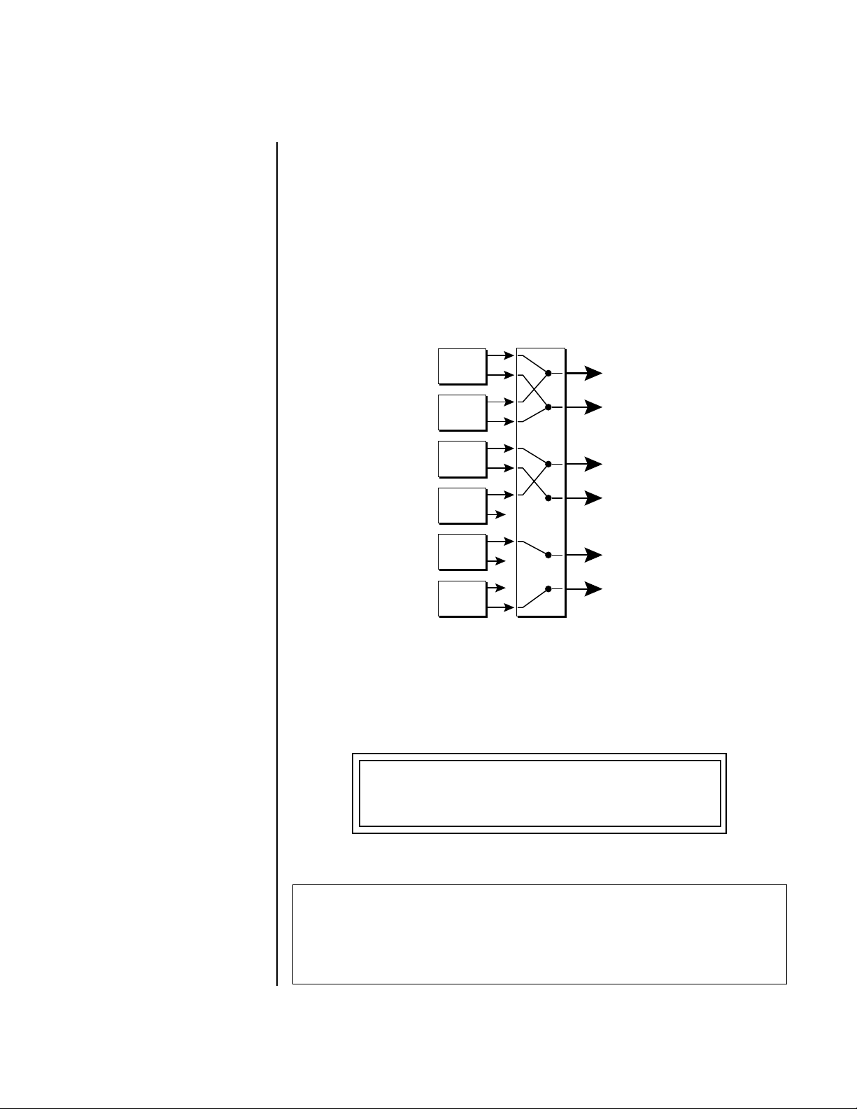
Programming Basics
Stereo Mix Outputs
Stereo Mix
Outputs
Virtuoso 2000 has three sets of polyphonic stereo outputs (Main, Sub 1 and
Sub 2). The channels used by a particular preset (or a particular MIDI
channel) can be directed to appear at any one of these three stereo outputs.
This feature is useful for adding signal processing (EQ, reverb, etc.) of
individual sounds prior to final mixdown. By panning a preset completely
left or right, it can be routed to a single output jack.
All presets are automatically routed to the Main outputs unless plugs are
inserted into the Sub 1 or Sub 2 outputs.
MIX
OUTPUT
Preset
000
L
Main
Preset
022
Preset
012
R
L
Sub1
Preset
127
Preset
018
R
L
Sub2
Preset
120
etc.
Each preset can be routed to one (and only one) set of stereo outputs. A preset can be
routed to a single output using the pan control.
R
The routing can be performed according to MIDI channel from the Mix
Output screen in the Master menu. Simply assign each channel to the
desired output.
MIX OUTPUT
channel 01A: Send 2
Sends DO NOT correspond to the same numbered Submix output numbers.
SEND ROUTINGS
Send 1 - Main Outputs
Send 2 - Submix 1 (or Main Outs if no plug is inserted into Submix jack)
Send 3 - Submix 2 (or Main Outs if no plug is inserted into Submix jack)
Send 4 - Main Outputs
Virtuoso 2000 Owner’s Manual 85
Page 94

Programming Basics
Stereo Mix Outputs
To route a particular preset to a Submix output, first go to the Mix Output
screen in the Master menu and set the MIDI channel to “Preset”.
MIX OUTPUT
channel 01A: Preset
Next set the Mix Output routing in the preset to the desired output (for
each layer). Yes, you can send each layer to a different output if you want.
L1
MIX OUTPUT
Send 2
Why have a Send 4 routing at all if it only goes to the Main output? The
answer lies in the dual function of the Sends. Sends can be used either as
Effect Sends or as External Output routing busses. Send 4 is only used as an
effect send, while Sends 2 and 3 can be used as effect sends or external
routing busses.
By sending different amounts of presets to the effects, subtle or striking
effects can be achieved using the two effect processors. This feature allows
you to get the most out of two effects since you can have eight different
mixes.
For more information, See “Mix Output” on page 40.
86 E-mu Systems
Page 95

Edit Menu
The Edit Menu contains four layers of preset parameters that you can
modify and then save as preset information in one of the user preset
locations.
There are four instrument layers in the Edit menu. See the illustration on
page 89 for a description of the Preset Layer model.
While the Edit menu is
activated, all incoming MIDI
preset changes on the selected
channel are ignored.
__
__
If there is no “A” option
in the Layer field, you must
enable the “Edit All Layers”
function in the Master Menu.
To Access the Edit Menu
Press the Edit button, lighting the LED. The Edit Menu screen displays the
menu page most recently selected since powering up Virtuoso 2000. The
cursor appears below the first character of the screen heading on line one.
To Scroll through Layers
Place the cursor below the layer field. Rotate the Data Entry Control to
select a layer (1-4).
You can also select All Layers by choosing “A” in the layer field. When All
Layers is selected, the existing parameter value for any field will be
displayed if the values of all four layers are equal. If the values of all four
layers are NOT equal, the value of layer 1 will be displayed with flashing
characters. If you change the parameter value, all layers will assume the
new value and the display will stop flashing.
To Scroll through Pages
Place the cursor below the page title field. This will automatically be done
when you press the Home/Enter button. Rotate the Data Entry Control to
scroll through the pages.
To Change a Parameter
Place the cursor below the parameter field. Rotate the Data Entry Control to
change the parameter value.
Virtuoso 2000 Owner’s Manual 87
Page 96

Edit Menu
Preset Name The Preset names consists of two parts: a 3 letter preset category and a 12
letter preset name. Position the cursor under the character location and use
the data entry control to change the character.
The preset category is used in conjunction with the Sound Navigator
feature. Using the Sound Navigator, a category is selected and the presets in
that category are listed in alphabetical order. Creating categories makes it
easier to find specific sounds when you need them. For more information
on Sound Navigator, see Sound Navigator in Chapter 2: Operations.
PRESET NAME
0020 vln: 16 Leg HP
The keyboard can also be used to select character. The charts below show
the keyboard character assignments.
%
*
#
(
!
+
&
b
l
"
a
$
n
k
,
'
)
-2
-1
0
1
2
3
6
1
4
/
-
0
.
9
5
2
7
3
8
;=@
:
<
B
E
?
D
A
>
C
GIL
F
H
N
Q
J
O
K
P
M
SUX
T
R
Z
]
Y
V
[
W
¥
_ad
^
`
f
c
e
b
g
C C# D D# E F F# G G# A A# B
blank
"!#$%&
'()*+,-./012
3456789: ; < >=
?@ABCDEFGHI J
KLMNOPQR STUV
WX Y Z [ ¥ ]^_`ab
h
kmp
i
j
l
n
o
q
r
wy|
u
s
t
v
Pitch
->
x
}
z
<-
{
88 E-MU Systems
4
5
6
Octave
cdefghijklmn
opqrstuvwxyz
{|}
Page 97

Edit Menu
Four Layer Architecture
Four Layer
Architecture
Virtuoso 2000 provides a 4 layer instrument structure. Each layer is a
complete synthesizer voice with 50 filter types, over 64 modulation sources,
more than 64 modulation destinations and 24 patchcords to connect everything together. In addition, the four layers can be crossfaded or switched by
key position, velocity or any real-time modulation source.
Instrument
Layer 1
Z-Plane Filter
DCA
R
Pan
L
Instrument
Layer 2
Z-Plane Filter
DCA
R
Pan
L
Instrument
Layer 3
Z-Plane Filter
DCA
R
Pan
L
Instrument
Layer 4
Z-Plane Filter
DCA
Pan
Selecting Layers In most of the Edit screens, the selected layer is shown in the upper left
corner of the display. Layers 1-4 or All can be selected by positioning the
cursor on this field and using the Data Entry Control to change the layer. In
the screen shown below, Layer 1 is selected.
L1
INSTRUMENT ROM:ORCH2
0
099 wnd:Oboe mf
When “All Layers” (A) is selected, the existing parameter value for any field
will be displayed if all layers are equal. If the layer parameter values are
NOT equal, the value of Layer 1 will be displayed with flashing characters.
If you move the Data Entry Control all values will be equal to this new
value and the parameter value will no longer flash.
R
L
Virtuoso 2000 Owner’s Manual 89
Page 98

Edit Menu
Defining Layer Parameters
Defining
Layer
Parameters
Selecting an Instrument
The Edit menu parameters define the four layers and include the
instrument assigned to the layer, the ranges of the layer, tuning, envelopes,
filters, and patch cords. These parameters are defined for each layer on an
individual basis (based on the currently selected layer). See “Common
Preset Parameters” on page 121 for global preset settings.
The Instrument parameter defines which of the available instrument
sounds is played by the current layer.
ROM SIMM Name
L1
INSTRUMENT ROM: ORCH2
0099 wnd:Oboe mf
Instrument Category Instrument Name
To select an instrument for the selected layer(s), move the cursor to the
bottom line of the display and change the instrument using the Data Entry
Control.
Sound Navigator
Sound Navigator also works to help select Instruments although the
category names are predefined. When the cursor is on the Instrument
Category field, turning the Data Entry Control selects different instrument
categories. The Name Field will change to show the first instrument in each
category. Move the cursor to the instrument name to select instruments in
the selected category.
L1
INSTRUMENT ROM: ORCH2
099 wnd:Oboe mf
0
1. Choose Category
Selecting Categories of Instruments using Sound Navigator.
2. Scroll through Instruments
90 E-MU Systems
Page 99

Edit Menu
Defining Layer Parameters
Defining Key Range The Key parameter defines the range on the keyboard used by the current
layer. The Key range is from C-2 through G8.
Middle C
C-2 C-1 C0 C1 C2 C3 C4 C5 C6 C7 C8 G8
To define the range, set the low key value and the high key value.
You can select key numbers by simply pressing the desired keyboard key
when the cursor is positioned on the low or high key field n the display.
Fade In Fade Out
L1
KEY: LO FADE HIGH FADE
C-2 000 C2 012
Layers can be crossfaded according to key position by adjusting the Low
and High Fade parameters. The first Fade field determines how many
semitones it takes the layer to Fade In from the low key. The second Fade
field determines how many semitones it takes the layer to Fade Out to the
high key. The screen shot above and the diagram below show Layer 1 being
faded out over a one octave range.
C-2 C-1 C0 C1 C2 C3 C4 C5 C6 C7 C8 G8
Layer 1
Layer 2
Layer 3
Switch
Layer 4
With a High Fade value of zero (as in layer 3 of the diagram), the layer
simply switches off at the high key.
Virtuoso 2000 Owner’s Manual 91
Page 100
You can select key
numbers by simply pressing the
desired keyboard key when the
cursor is positioned on the low
or high key field n the display.
Edit Menu
Defining Layer Parameters
To Switch Layers According to Key Position
The Key Range parameter allows you to create a “split” keyboard with up to
four sounds adjacent to each other on the keyboard. This is shown in the
diagram below.
C0 C1 C2 C3 C4 C5 C6
Layer 1 Layer 2 Layer 3 Layer 4
Switch Switch Switch
Just assign the low and high key range for each of the four layers with Fade
set to zero. Set the Low and High Keys so they don’t overlap other layers.
L1
KEY: LO FADE HIGH FADE
C0 000 F1 000
L2
KEY: LO FADE HIGH FADE
L3
C
L4
G
If two layers do overlap, both will play as shown in the next example.
F#1 000 C3 000
KEY: LO FADE HIGH FADE
#3 000 F#4 000
KEY: LO FADE HIGH FADE
4 000 C6 000
92 E-MU Systems
 Loading...