

Page 1
Owner’s ManualOwner’s Manual
0204 USB Owner’s Manual 1
Page 2

Owner’s Manual
© 2010 E-MU Systems
All Rights Reserved
Revision: Revision A
E-MU World Headquarters
E-MU Systems
1500 Green Hills Road
Scotts Valley, CA 95066
USA
Europe
Creative Labs (Ireland) Ltd
Ballycoolin Business Park
Blanchardstown, Dublin 15
IRELAND
2 E-MU Systems
Page 3

TABLE OF CONTENTS
Introduction .................................................................................5
Package Includes .......................................................................... 6
Computer Requirements ............................................................... 7
Windows ..........................................................................................................7
OS X .................................................................................................................7
Software Installation .................................................................... 8
Windows XP, Windows Vista or Windows 7 ......................................................8
Note About Windows Logo Testing ................................................................ 8
Uninstalling all Audio Drivers and Applications ................................................8
Macintosh OS X .................................................................................................9
Uninstalling the Audio Drivers and Applications ............................................11
Connection Diagram .................................................................. 12
Controls & Headphone Output ................................................... 13
Input/Output .............................................................................14
E-MU USB Audio Control Panel ...................................................15
Headphone Source .....................................................................16
Direct Monitoring .......................................................................17
Audio Recording Software ..........................................................18
Troubleshooting .........................................................................19
Internet References ....................................................................20
Forums ........................................................................................................20
Technical Specifications .............................................................. 21
Adapter Cables ........................................................................... 23
1/8” Headphone to 1/4” Headphone Adapter ..............................................23
Stereo Headphone to 2 x 1/4” Jack Splitter Cable ..........................................23
Declaration of Conformity .......................................................... 24
0204 Block Diagram ................................................................... 26
Index ......................................................................................... 27
0204 USB Owner’s Manual 3
Page 4

4 E-MU Systems
Page 5
Introduction
INTRODUCTION
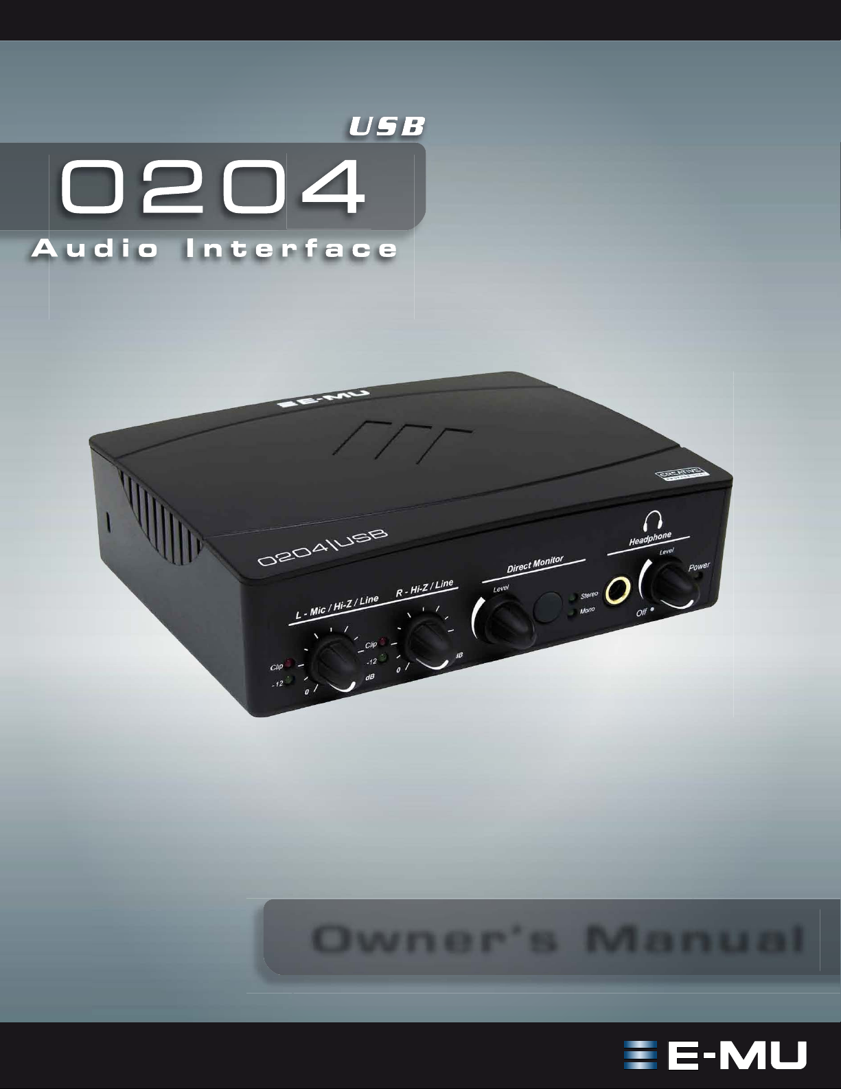
Thanks for your purchase of the E-MU 0204 USB Audio Interface. The 0204
provides 2 analog inputs, 4 analog outputs and brings an unparalleled level of USB
audio quality to the Mac or PC, with pristine 24-bit/192kHz A/D and D/A
converters, ultra-low jitter clock, and Class-A, ultra-low noise mic/line/hi-Z
preamps. The signal-to-noise specs of the E-MU 0204 USB are unmatched by any
other USB interface on the market! From its plug-and-play functionality and
hands-on ergonomic design, to professional features like zero-latency direct
monitoring, the USB will forever change your expectations of USB audio.
Some of the other key features are detailed below:
• Record and playback support for a multitude of sample rates: 44.1k, 48k, 88.2k,
96k, 176.4k, 192k (176.4k &192k available on PC version only)
• Zero-latency direct hardware monitoring (disabled at 176.4k and 192k on the
Macintosh)
• Full 24-bit resolution and stereo-in/stereo-out at all sample rates
• Independent ground lift switches for both analog inputs help to solve potential
ground loop problems
• Headphone output can be used as separate stereo output from your software
with analog volume control
• Studio-grade headphone amplifier
• Anti-pop speaker protection minimizes noise during power on/off
• Ultra-low jitter clock subsystem: <100ps RMS
• Windows drivers: ASIO2 and WDM
• Macintosh driver: Apple CoreAudio
NOTE
There are some limitations
when operating at higher
sample rates. See page 15
for details.
• Kensington security lock
0204 USB Owner’s Manual 5
Page 6

Package Includes
PACKAGE INCLUDES
• E-MU 0204 USB AudioPod
•USB cable
• 0204 USB installation guide
E-MU Software/Manual CD-ROM (OS X /Windows)
• Windows XP, Windows Vista/x64, Windows 7/x64 drivers
•Mac OS X drivers
• Owner’s manual and tutorials
Acoustica Mixcraft LE 4 Install CD-ROM (Windows)
• Acoustica Mixcraft LE (multitrack recording application)
6 E-MU Systems
Page 7

Computer Requirements
COMPUTER REQUIREMENTS
The recommended computer system requirements for the E-MU 0204 USB are
listed below.
Windows
• Intel® Pentium® or AMD® processor — 1.2 GHz or faster
• Intel, AMD, or 100% compatible motherboard & chipset
• Microsoft® Windows® XP (SP3 or greater), Vista/x64, Windows 7/x64 Drivers
• 1 available (Hi-Speed) USB 2.0 port
•1GB System RAM
• 950 MB of free hard disk space for full installation
• CD-ROM/CD-RW or DVD-ROM drive required for software installation
• XVGA Video (1024 x 768)
OS X
• Apple® Macintosh® Intel-based processor — 1.2 GHz or faster
NOTE: For more information on Intel Mac support see the included ReadMe file,
and/or www.emu.com
for latest information.
• Apple Macintosh OS X, 10.5 or greater
• 1 Available (Hi-Speed) USB 2.0 port
•1GB System RAM
• 500MB of free hard disk space for full installation
• CD-ROM/CD-RW or DVD-ROM drive required for software installation
• XVGA Video (1024 X 768)
0204 USB Owner’s Manual 7
Page 8

Software Installation
SOFTWARE INSTALLATION
Windows XP, Windows Vista or Windows 7
Follow these instructions to install the 0204 USB software on a Windows
computer.
1. First connect the 0204 USB to your computer using the supplied USB cable,
and turn it on.
2. If Windows prompts you with an Add New Hardware Wizard, click Cancel.
3. Insert the E-MU software Installation CD into your CD-ROM drive. If
Windows AutoPlay mode is enabled for your CD-ROM drive, the CD starts
running automatically. If not, from your Windows desktop, click Start->Run
and type d:\setup.exe (replace d:\ with the drive letter of your CD-ROM
drive). You can also simply open the CD and double-click Setup.exe.
4. The installation splash screen appears. Follow the instructions on the screen to
complete the installation.
5. Choose “Continue Anyway” when you encounter the “Windows Logo
Testing” warning screen. See the note below.
6. When prompted, restart your computer.
7. Be sure to register your 0204 USB so we can advise you of future software
updates and special offers. You can register online at: www.emu.com/register
8. Your 0204 USB is now ready to use.
9. Insert the Acoustica Mixcraft LE 4 Install CD-ROM into your CD-ROM drive.
10. The installation splash screen appears. Follow the instructions on the screen to
complete the installation.
Note About Windows Logo Testing
When you install the 0204 USB drivers, you will see a dialog box informing you
either that the driver has not been certified by Windows Hardware Quality Labs
(WHQL), or that the driver is signed by Creative Labs, Inc., and you will be asked if
you would like to continue with the installation.
The 0204 USB audio drivers are not certified by WHQL because the product does
not support some of the features that the Microsoft Windows Logo Program
requires, most notably Universal Audio Architecture (UAA) and Digital Rights
Management (DRM).
Despite this, the 0204 USB audio drivers have been rigorously tested using the
same test procedures that a WHQL qualified driver requires, and it passes in all of
the other important categories, including those that measure the relative stability
of the driver. So, it is perfectly safe to install these drivers on your computer.
Uninstalling all Audio Drivers and Applications
At times you may need to uninstall or reinstall the 0204 USB application and
device drivers to correct problems, change configurations, or upgrade outdated
drivers or applications. Before you begin, close the E-MU USB 2.0 Audio control
application. Applications running during the uninstallation will not be removed.
1. Click Start -> Control Panel.
2. Double-click the Add/Remove Programs icon.
3. Click the Install/Uninstall tab (or Change or Remove Programs button).
4. Select the E-MU 0204 USB entry and then click the Change/Remove button.
5. In the InstallShield Wizard dialog box, select the Remove ALL option.
8 E-MU Systems
Page 9

Software Installation
6. Click the Yes button.
7. Restart your computer when prompted.
You may now re-install existing or updated E-MU device drivers or applications.
Macintosh OS X
Follow these instructions to install the 0204 USB drivers and software on a
Macintosh OS X computer. First, connect the 0204 USB to your computer as shown
on page 12
Install the 0204 USB Software
1. Insert the E-MU Software/Manual CD-ROM into your CD-ROM drive.
2. Double-click on the E-MU icon on the desktop.
3. Double-click on the Install icon to start the installation.
4. The installation Welcome screen appears. Follow the instructions on the
5. When the Authenticate dialog box appears, enter the administrator password
6. Continue to follow the instructions on the screen to continue the installation.
• Easy Install: Installs the following applications and drivers.
• Custom Install: allows you to choose which components are installed.
7. Easy Install is recommended. The software will be quickly installed. When
.
screen.
you chose when you installed OS X.
You will be given the option to install:
E-MU 0204 USB: USB Drivers and Control Application
prompted, restart your computer.
8. Be sure to register your 0204 USB so we can advise you of future software
updates and special offers. You can register online at: www.emu.com/register
Set-up the 0204 USB as your Default Audio Device
9. Click Go -> Utilities from the menu bar.
10. Double-click Audio MIDI Setup, then click the Audio Devices button if it’s
not already selected. The window shown on the following page appears.
11. Select the 0204 USB for the following: Default Input, Default Output, System
Output, Properties For.
12. Play a song on iTunes to verify that the 0204 USB is the default device for
audio playback.
13. Quit iTunes.
0204 USB Owner’s Manual 9
Page 10

Software Installation
NOTE: If you already have
a MIDI Interface connected,
you can skip steps 14-19.
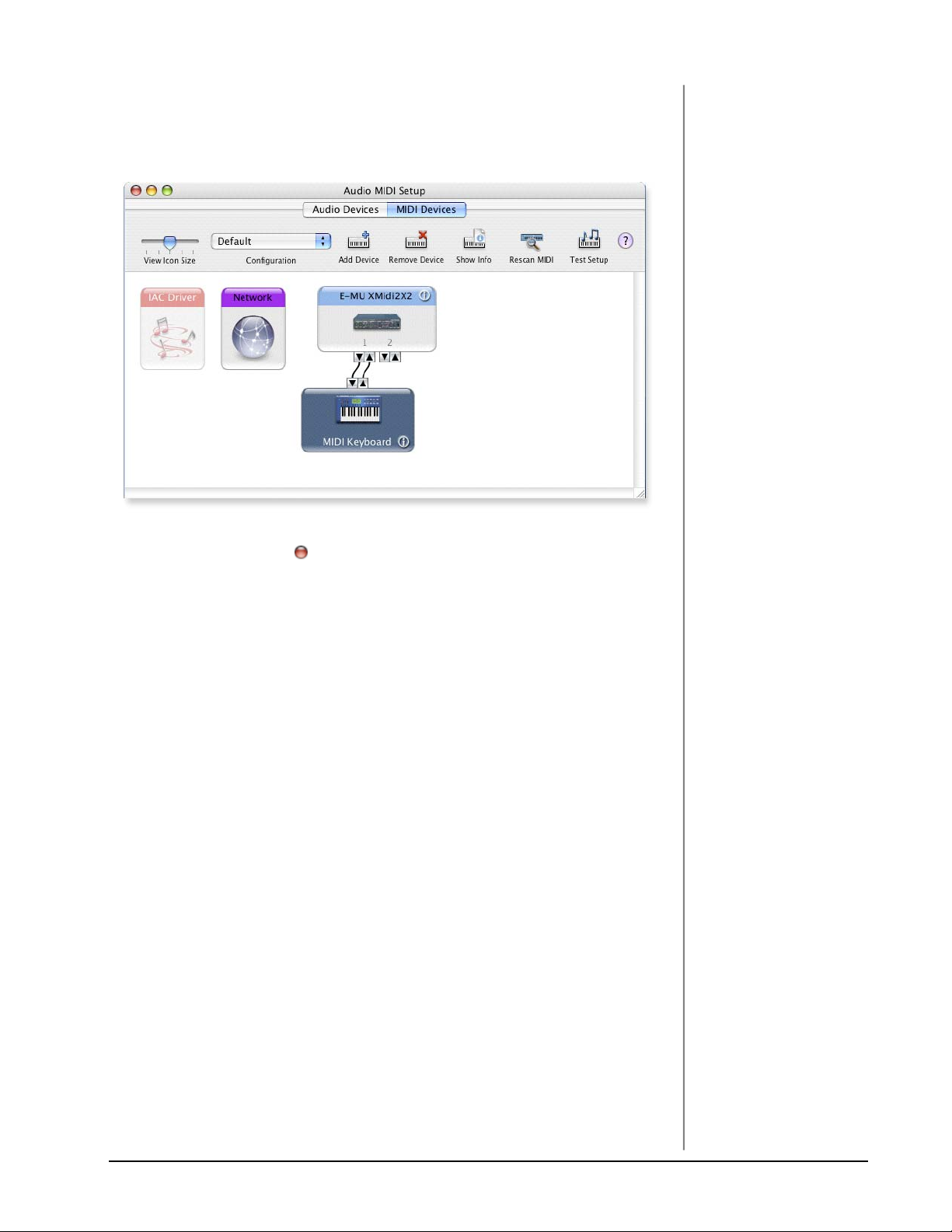
Setup the MIDI Devices
If you plan to use a MIDI keyboard, now would be a good time to set up your MIDI
devices. Connecting a MIDI keyboard will allow you to use the virtual instruments
provided in the software bundle and get the most out of your purchase. You’ll also
need a MIDI interface such as the E-MU Xmidi 2x2 or Xmidi 1x1.
14. Click the MIDI Devices button. The window shown below appears.
15. Click the Add Device button. A new external
device icon like the one shown at right appears.
16. Double-click on the new external device if you
want to set the MIDI Keyboard Properties. You
have the option to name and change the icon
for the device. Click Apply, then click the Close
button to close the Properties window.
10 E-MU Systems
Page 11
Software Installation
17. Connect the new external device to the E-MU 0204|USB by dragging between
the input and output connectors.
18. The window below shows a properly connected MIDI device.
19. Press the close button to close the Audio MIDI Setup window.
Uninstalling the Audio Drivers and Applications
At times you may need to uninstall or reinstall the 0204 USB application and
device drivers to correct problems, change configurations, or upgrade outdated
drivers or applications. Before you begin, close the E-MU USB 2.0 Audio control
panel application. Applications running during the uninstallation will not be
removed.
1. Open the Applications folder.
2. Open the Creative Professional folder.
3. Open the E-MU USB Audio folder.
4. Click the E-MU USB Audio Uninstaller and follow the instructions.
0204 USB Owner’s Manual 11
Page 12

Connection Diagram
WARNING!
Use only a USB 2.0
certified Hi-Speed cable
(like the one supplied) for
the USB connection. Using
a USB 1.1 cable may cause
erratic behavior and
degraded performance.
CONNECTION DIAGRAM
Microphone
or Line
Computer
Electret
Mic
1/4” male to 1/4” male
(unbalanced)
Powered Speakers
12 E-MU Systems
Page 13

Controls & Headphone Output
CONTROLS & HEADPHONE OUTPUT
7
1
1. Signal Level & Clip Indicators
The LED signal level indicators make it easy for you to set a proper signal
level. When the input level is too low, the green and red LEDs will both be off.
When the input level is correctly set, the green signal LED should be flickering. If the signal level is too high, the green and red LEDs will both be on.
The red clip indicators show that the input level has exceeded 0dBFS.
2. Left/Right Gain Controls
These controls set the input gain from 0dB to +60dB for the two inputs.
3. Direct Monitor Level Control
This digital encoder controls how much of the input signal is mixed with the
signal from the computer and is adjustable from unity gain (no attenuation)
to off. This feature allows you to hear your instrument through the monitor
speakers while you are recording. The Direct Monitor Control does not have
end-stops like the other controls and you may have to turn it more than one
revolution to set the desired level.
4. Direct Monitor On/Off & Mono-Stereo Switch
Press the button to turn Direct Monitoring on and off and to switch modes.
The stereo LED illuminates. The left and right channels are passed through to
their respective outputs at the level set by the Direct Monitor Level control.
Press the button again to sum the left and right direct monitor channels to
mono. Mono mode is useful when the two inputs are being used for separate
instruments. See “
Direct Monitoring” on page 17.
3 5 624
5. Headphone Jack
This is a 1/4” jack to connect your stereo headphones. If your headphones use
the smaller 1/8” plug, you’ll need an adapter of the type shown on page 23
The stereo headphone channels can be configured to be independent of the
main outputs. This allows you to create a separate headphone mix in your
recording application or use the headphone jack as another pair of outputs.
See page 23
6. Headphone Level Control / Power Switch
This knob controls the volume of the headphone output. This switch also
turns the 0204 USB on or off.
7. Kensington Security Lock
0204 USB Owner’s Manual 13
for an illustration of a headphone adapter cable.
.
Page 14

Input/Output
INPUT/OUTPUT
8 10 11 12913
8. USB
Connects the 0204 USB to your computer via the supplied USB cable. The
USB connection provides two-way communication when connected to the
computer.
The 0204 USB receives its power from the USB. Always connect to the USB
jack on the computer itself and NOT to a low-power USB connection that
may be present on your computer keyboard or other USB peripheral.
System Volume Control
Mac
PC
9. Main Outputs
The unbalanced outputs are normally connected to your monitoring system.
The signal is duplicated on a stereo 1/8¨ jack for easy connection to desktop
stereo speakers. The outputs have been designed using a special noisecancelling circuit which reduces problems relating to ground loops.
The main output volume can be controlled using the System Volume Control
on your Mac or PC (WDM only on PC).
10. R - Hi Z / Line Input
This 1/4¨ input can be used as a Hi-Z instrument input (guitar/bass, etc.) or a
line level input. The input is balanced, but accepts either balanced or unbalanced signals.
11. L - 1/8¨ Mic Input
This 1/8” mini-phone jack is designed to accept an electret condenser micro-
phone. The jack supplies +5VDC phantom power required by electret mics.
12. L - Hi-Z / Line / Mic Input
Use the XLR connector for microphones or balanced line level signals. Use the
1/4¨ in the center of the XLR jack as a Hi-Z input for guitar/bass, or as a line
level input. The input is balanced, but accepts either balanced or unbalanced
signals.
13. Ground Lift Switches
The “ground lift” switches, located on the bottom of the unit, can be used to
safely stop the hum if a ground loop occurs in your setup. See page 19
more information.
for
Input Grounded
R-GND LIFT
L-GND LIFT
The input ground is lifted when the A or B slide switch is closest to the GND LIFT label.
14 E-MU Systems
Input Ground Lifted
Page 15

E-MU USB Audio Control Panel
E-MU USB AUDIO CONTROL PANEL
After you have successfully installed the audio drivers, launch the E-MU USB
Audio control panel. The E-MU USB Audio Control Panel is shown below.
• Windows: The E-MU USB Audio control icon will be visible in the Taskbar,
which is normally located in the bottom right of the screen. It can
also be launched from the Start Menu
(All Programs, Creative Professional, E-MU USB Audio Application).
• OS X The E-MU USB Audio control application is located in the Applications folder . You can also open the application using the
icon on the desktop.
23
1
4
5
6
7
1. Skin
Choose between several different appearances for the control panel.
2. View
Hide the application (Ctrl+H, Windows). You can restore the application by
clicking the E-MU icon in the System Tray (Windows), or by clicking the
E-MU icon in the Dock (OS X).
3. Help
About E-MU 0204 USB, Audio control, Launch Manual, Check Updates.
4. Device
If you are using more than one E-MU USB Audio device, you can choose
which unit is currently being controlled.
5. Sample Rate
Allows you to set the system sample rate: 44.1, 48, 88.2, 96, 176.4 or 192 kHz.
6. Headphone Source
The Headphone Source controls whether the headphone output monitors the
MainOut 1/2 or receives its signal from Aux 3/4 of your software application.
The default setting is Main Out 1/2 (Headphones monitor main outputs). Refer
to the following page for more information about this control.
NOTE
Macintosh operation up to
96kHz only at this time –
check www.emu.com for
updates
7. USB Speed
Indicates if you are connected to a USB 1.1 or USB 2.0 port on your computer.
0204 USB Owner’s Manual 15
Page 16

Headphone Source
HEADPHONE SOURCE
The stereo headphone output can either duplicate the main outputs, or it can be
used as another completely independent pair of outputs when using ASIO. This
setting is controlled from the 0204 Control Panel. The headphone output is a highquality signal, with increased power for driving headphones.
With the Headphone Source set to Main Out 1/2, the headphone output duplicates
the signal on the main outputs. With the Headphone Source set to Aux 3/4, the
headphone output receives its signal from outputs 3/4 of your software application.
Headphones Duplicate Main Outputs (Headphone Source = Main Out 1/2)
This is the setting you’ll normally want if you’re only using one pair of outputs,
such as stereo recording/playback or listening to music. This is the default setting.
Separate Headphone Mix
By selecting Headphone Source Aux 3/4, you can create a separate headphone mix
for live performance or while recording.
Two Additional Outputs
With an appropriate cable adapter (see page 23
another pair of signal outputs (3/4). The headphone signal is of the same exceptional quality as the main outputs with the addition of an analog volume control.
Note: At the highest sample rates (176.4/192 kHz), the Headphone Source feature
is disabled. In this case, the headphone output duplicates the main outputs.
The Headphone Source feature is also disabled when using WDM on a Windows
computer. In this case, setting the Headphone Source to Aux 3/4 will turn off the
headphone output.
16 E-MU Systems
), the headphone output becomes
Page 17

Direct Monitoring
DIRECT MONITORING
Direct monitoring allows you to monitor inputs without having any software
open. It can also be used as an alternative to software monitoring if you desire the
lowest latency monitoring possible.
When using a computer for digital recording, an audible time delay occurs while
the audio signal is being input to the computer, processed by the software and then
returned to the output for monitoring. This time delay is called Latency.
Latency becomes a problem when you have to use high buffer settings to conserve
CPU resources. Because the 0204 USB has hardware direct monitoring, you can
enjoy zero latency regardless of your buffer setting.
The Direct Monitor feature connects the input signals to the output when recording
so that you can hear your performance without delay. The Direct Monitor level
control lets you adjust the volume of the input signal in relation to the recorded
tracks.
Direct monitoring is controlled manually from the Direct Monitor switch on the
0204 USB. It’s not necessary to turn it on in your recording application.
Latency (delay)
USB
NOTE
Direct monitoring on
channels 1/2 only at 176.4
or 192 kHz sample rates.
Software Monitoring
Direct Monitoring
Direct Monitoring allows you to listen to the direct sound of your instrument during
recording, without the delay incurred by going to the computer and back.
Direct Monitoring vs. Software Monitoring
Direct monitoring is lower latency and can also be used without software running.
Software monitoring has the advantage of allowing audio effects or EQ added in
the host software to be heard on the output. Its round-trip latency depends on
what latency is chosen in the ASIO configuration. If you choose to software
monitor, make sure to disable direct monitoring. If both are enabled, you will
experience a ‘comb filter’ or doubling effect.
0204 USB Owner’s Manual 17
Page 18

Audio Recording Software
AUDIO RECORDING SOFTWARE
Now that you’ve installed the 0204 USB, you probably want to start using it! The
0204 USB is only one half of the equation—the hardware interface that translates
audio signals into the digital language of your computer. The second half of the
equation is the software recording application, which records and allows you to
edit the audio on your computer.
WARNING!
Windows Users - After
checking your audio, be
sure to quit Windows
Media Player.
Acoustica Mixcraft LE 4
™
We have included Acoustica Mixcraft LE 4 for PC users. Acoustica Mixcraft LE 4 is
a full-featured multitrack recording application with effects, virtual instruments,
™
and DirectX™ support and much more.
VST
Tutorials and Videos: http://www.acoustica.com/mixcraft/support.htm
Macintosh Users
Unfortunately we were not able to include a Macintosh recording application with
the 0204 USB, however you can use Garage Band, a very cool music application
that probably came bundled with your Mac. This application works well with the
0204 USB and will get you started with audio recording.
NEED MORE HELP?
If you need additional help, please see:
• Windows: Program Files\Creative Professional\E-MU 0204
USB\Documents\3rdParty.htm
• OS X: Applications Drive\Library\Documentation\E-MU 0204 USB\
3rdParty.htm
Before you Begin...
• You should have already installed the E-MU software on your computer
• You should hear the computer sounds coming out of the E-MU 0204 USB
and your speakers when you play a CD or an MP3 using Windows Media
Player or iTunes. If not, make sure your E-MU 0204 USB is properly
connected according to the diagram on page 12
• A source of audio should be connected to the inputs (a microphone, musical
instrument, or CD/MP3 player).
.
18 E-MU Systems
Page 19

Troubleshooting
TROUBL ESHOO TING
Can’t hear Windows Media Player in Windows
If you have, or ever have had, another audio device installed in your PC, you may
have to set the E-MU 0204 USB as the “Default Audio Device”.
1. Open the Control Panel, then select Sounds and Audio Devices.
2. Click the Audio tab and select the E-MU 0204 USB as the Default device under
Sound Playback.
3. Click the Volume button under Sound Playback and turn up Wave volume.
You cannot record or monitor ASIO and WAVE at the same time. The first audio
application you open controls the E-MU 0204 USB.
Lost Communication
Should you lose communication between your E-MU 0204 and an audio application (Ableton Live, Cubase, Sonar, etc.), the E-MU 0204 USB drivers may need to
be re-selected in your application.
1. Go to your application's I/O settings, de-select the E-MU 0204 USB for both
input and output.
2. Apply these changes and exit the dialog.
3. Re-enter the application's preference settings and re-select the E-MU 0204 USB
drivers. If this doesn’t work, the application may need to be restarted.
Ground Loops
In digital audio devices and computers, audio ground loops may appear as pitched
tones, digital hash in the background, as well as the familiar 50/60 cycle hum.
Ground loops are caused by a difference in ground potential between two pieces of
equipment. Computer audio devices are particularly susceptible to ground loops
because most computers were not designed with high quality audio in mind.
The E-MU 0204 USB contains built-in “ground lift” switches for both analog
inputs in order to safely break the loop if a ground loop occurs in your setup.
Input Grounded
R-GND LIFT
L-GND LIFT
The ground-lift switches are located on the bottom of the unit, close to the rear
panel. The input ground is lifted when the A or B slide switch is closest to the GND
LIFT label.
Pops & Crackles
Pops and crackling noises in the audio are most often caused by having the ASIO
Buffer Size set too low. Adding audio tracks and VST plug-ins increases the load on
your computer’s CPU. If your computer cannot keep up with all the tasks you are
asking it to perform, pops and crackles may occur. In effect, increasing the ASIO
buffer gives your computer “more time” to complete its assigned tasks. The
hardware Direct Monitor feature of the 0204 USB allows you to increase the ASIO
Buffer setting without the associated latency problems during recording and
overdubbing.
USB hubs can create problems with digital audio and should be avoided whenever
possible.
Input Ground Lifted
0204 USB Owner’s Manual 19
Page 20

Internet References
Simultaneous WDM/ASIO Playback (PC only)
The 0204 USB only supports playing back one stream format at a time on the PC.
Each of the two mentioned stream types has an associated priority. If a higher
priority stream type is opened while a lower priority stream is already playing, the
lower priority stream will stop playing. The stream priorities, from highest to
lowest, are ASIO, WDM.
Headphone Source using WDM (PC only)
The Headphone Source feature only functions using ASIO at this time. The
Headphone output will be disabled if the Headphone Source in the 0204 USB
Control Panel is set to Aux 3/4.
USB 1.1 vs USB 2.0 Ports
The 0204 requires a USB 2.0 port for error-free audio performance. The E-MU USB
Audio Control panel indicates if you are connected to a USB 1.1 or USB 2.0 port on
your computer.
0204 USB comes up in USB 1.1 mode (PC only)
Always turn the 0204 USB power off before connecting or disconnecting the USB
cable. Hot-plugging the unit with the power on can cause the 0204 to power-up in
USB 1.1 mode. If you see the Windows message, “This device could perform
faster…”, simply turn power off, wait a few seconds, then turn power on again.
INTERNET REFERENCES
The internet contains vast resources for the computer musician. A few useful sites
are listed here, but there are plenty more. Check it out.
Software Updates, Tips & Tutorials . http://www.emu.com/support
Setting up a PC for Digital Audio .... http://www.musicxp.net
MIDI Basics.......................................... Search for “MIDI Basics” (many sites)
MIDI & Audio Recording................... http://www.midiworld.com
MIDI & Audio Recording................... http://www.synthzone.com
Mixcraft ................................................ http://www.acoustica.com/mixcraft/
index.htm
Forums
Unofficial E-MU Forum..................... http://www.productionforums.com/emu
Sound-On-Sound Forum .................. http://www.soundonsound.com
Computer Music Forum .................... http://www.musicradar.com/computermusic
Home Recording Forum.................... http://homerecording.com/bbs
Studio Central Forum ........................ http://www.tweakheadz.com
KVR Forum .......................................... http://www.kvraudio.com/forum
Sound Card Benchmarking............... http://audio.rightmark.org
Driver Heaven Forum ........................ http://www.driverheaven.net
20 E-MU Systems
Page 21

Technical Specifications
TECHNICAL SPECIFICATIONS
General
• Sample Rates: 44.1, 48, 88.2, 96, 176.4, 192kHz from internal crystal with no
sample rate conversion *
• Bit Depth: 24-bit I/O, 32-bit processing
• USB 2.0 Hi-Speed
• Full 24-bit resolution at all sample rates
• 2 in/4 out channels
• Zero-latency direct hardware monitoring
(Direct monitor on channels 1/2 only at 176.4/192kHz sample rates)
• Windows drivers: ASIO2 and WDM
• Macintosh driver: Apple CoreAudio
• Anti-Pop speaker protection minimizes noise during power on/off
• Ultra-low jitter clock subsystem: <100ps RMS
Combo Preamplifiers
• Type:
• (1) Ultra-low noise combo preamplifier with Mic/ Hi-Z/line inputs
• (1) Combo preamplifier with Hi-Z/ balanced input
• (1) 1/8” condenser mic input with 5V power
• A/D Converter: AK5385
• Max. Level: +6.5dBV (+8.7dBu)
• Input Impedance: 1.5 kOhms
• Frequency Response (min gain, 20Hz-20kHz): +0.0/-0.07dB
• Dynamic Range (A-weighted, 1kHz, min. gain): 113dB
• Signal-to-Noise Ratio (A-weighted, min. gain): 113dB
• THD+N (1kHz at - 1dBFS, min. gain): -101.9dB (.0008%)
• Ultra-low noise preamplifier (Mic/Hi-Z/line inputs)
• Input Impedance: 1.5Kohm
• EIN (20Hz-20kHz, 150ohm, unweighted): -127dBu
• Combo preamplifier with Hi-Z/line balanced input - Input Impedance:
1Mohm
Analog Line Outputs (2)
• Type: balanced, AC-coupled, 2-pole low-pass differential filter
• D/A converter: AK4396
• Max Level: 6.7 dBV (unbalanced)
• Frequency Response (20Hz - 20kHz): 0.00/-0.01dB
• Dynamic Range (1kHz, A-weighted): 117dB
• Signal-to-Noise Ratio (A-weighted): 117dB
• THD+N (1kHz at -1dBFS): -101.9dB (.0008%)
• Stereo Crosstalk (1kHz at -1dBFS): -111dB
0204 USB Owner’s Manual 21
Page 22

Technical Specifications
Headphone Amplifier
• Type: Class-A power amplifier
• D/A converter: AK4396
• Gain Range: 60dB
• Maximum Output Power: 16mW
• Output impedance: 22ohms
• Frequency Response (20Hz-20kHz): +0.02/-0.08dB
• Dynamic Range (A-weighted): 117dB
• Signal-to-Noise Ratio (A-weighted): 117dB
• THD+N (1kHz, max gain): 300ohm load: -101.9dB (.0008%)
• Stereo Crosstalk (1kHz at -1dBFS, 300 ohm load): -107dB
Synchronization
• Internal crystal sync at 44.1, 48, 88.2, 96, 176.4, 192kHz*
Dimensions/Weight:
• Weight: 0.94 lb / 0.43 kg
• Dimensions:
W: 6.5” H: 2.0” L: 5.5”
W: 165 mm H: 50.8 mm L: 140 mm
* Macintosh operation up to 96kHz only at this time – check www.emu.com for updates
22 E-MU Systems
Page 23

Adapter Cables
ADAPTER CABLES
1/8” Headphone to 1/4” Headphone Adapter
Stereo Headphone to 2 x 1/4” Jack Splitter Cable
RING
TIP
This type of adapter allows you to use the Headphone jack as another pair of line outputs.
The tip and ring of the headphone plug are split off into separate outputs.
0204 USB Owner’s Manual 23
Page 24

Declaration of Conformity
DECLARATION OF CONFORMITY
Trade Name: E-MU Systems
Model No.: EM8740A
Responsible Party: E-MU Systems
Address: 1500 Green Hills Road
Scotts Valley, CA 95066 U.S.A.
This device complies with Part 15 of the FCC rules. Operation is subject to the
following two conditions: (1) This device may not cause harmful interference, and
(2) this device must accept any interference received, including interference that
may cause undesired operation.
CAUTION
You are cautioned that any changes or modifications not expressly approved in
this manual could void your authority to operate this equipment.
Note:
This equipment has been tested and found to comply with the limits for a Class B
digital device, pursuant to Part 15 of the FCC Rules. These limits are designed to
provide reasonable protection against harmful interference in a residential installation. This equipment generates, uses, and can radiate radio frequency energy
and, if not installed and used in accordance with the instructions, may cause
harmful interference to radio communications. However, there is no guarantee
that interference to radio or television reception, which can be determined by
turning the equipment off and on, the user is encouraged to try to correct the interference by one or more of the following measures:
• Reorient or relocate the receiving antenna.
• Increase the separation between the equipment and receiver.
• Connect the equipment into an outlet on a circuit different from that to
which the receiver is connected.
• Consult the dealer or an experienced radio/TV technician for help.
The supplied interface cables must be used with the equipment in order to comply
with the limits for a digital device pursuant to Subpart B of Part 15 of FCC Rules.
24 E-MU Systems
Page 25

Declaration of Conformity
Compliance Information
United States Compliance Information
FCC Part 15 Subpart B Class B using:
CISPR 22 (1997) Class B
ANSI C63.4 (2003) method
FCC Site No. 958979
Canada Compliance Information
ICES-0003 Class B using:
CISPR 22 (1997) Class B
ANSI C63.4 (2003) method
Industry of Canada File No. IC 5933
European Union Compliance Information
EN55024 (1998 w/A1:01 & A2:03)
EN55022 (1998) Class B
Australia/New Zealand Compliance Information
AS/NZS CISPR 22 (2002) Class B using:
EN55022 (1998) Class B
Japan Compliance Information
VCCI (April 2005) Class B using:
CISPR 22 (1997) Class B
ANSI C63.4 (2003) method
VCCI Acceptance Nos. R-2160 & C-2332
Attention for the Customers in Europe
This product has been tested and found compliant with the limits set out in the
EMC Directive for using connection cables shorter than 3 meters (9.8 feet).
Notice
If static electricity or electromagnetism causes data transfer to discontinue midway
(fail), restart the application or disconnect and connect the USB cable again.
0204 USB Owner’s Manual 25
Page 26

0204 Block Diagram
USB
Record
2
1
(computer)
0204 BLOCK DIAGRAM
MAIN L
(chan.1)
MAIN R
(chan.2)
DAC
DAC
DAC
Phones
Out
(channel
1/2 or 3/4)
DAC
Volume
Headphone
Source
Headphone
USB Control Panel)
(Select from E-MU
Meter
Gain
2
ADC
1
Mic In
3
Ground
LEFT
Lift
Meter
Bal/Unbal
Line/Instr In
5V
Mic In
Electret
Gain
Mono/
ADC
Bal/Unbal
Line/Instr In
RIGHT
Off
Stereo/
Lift
Ground
Direct
Monitor
Level
3/4 not available at 176k/192k sample rates
1
2
3
4
USB
(computer)
Playback
0204 USB BLOCK DIAGRAM
26 E-MU Systems
Page 27

Index
INDEX
A
Acoustica Mixcraft LE 4
Adapter Cables
ASIO Buffer Size
B
Block Diagram
C
Clip Indicators
Computer Requirements
Connection Diagram
Control Panel
D
Device Select, E-Control
Direct Monitor Controls
Direct Monitoring
Direct Monitoring vs Software Monitoring
23
19
26
13
15, 16
18
7
12, 14
15
13
17
17
M
Main Output Volume Control
Monitoring, direct vs software
O
Output Volume Control
Outputs 3/4
P
Package Contents
Pops & Crackles
R
Recording Software
S
Signal Level Indicators
Signal Routing Diagram
Simultaneous WDM/ASIO/AC-3 Playback
Skin, selecting
Software Installation
Mac OSX
Windows
T
Technical Specifications
Testing Your Interface
Troubleshooting
16
8
19
18
13
15
9
8
18
19
14
17
14
26
21, 23
20
E
E-Control Application
G
Gain Controls
Ground Lift Switches
Ground Loops
H
Headphone Level Control
Headphone Mix, creating
Headphone Output
Headphone Source
Hi-Z Input
I
Inputs
Internet References
L
Latency
Lost Communication
14
13
19
14
17
15
14, 19
14
16
20
19
13
16
U
Uninstalling Drivers & App
USB 1.1 Warning Message
USB Jack
V
Volume Control, controlling with computer
W
WDM/ASIO/AC-3 Playback
Windows Logo Testing Note
Windows Media Player, no audio
14
8, 11
20
20
8
19
14
0204 USB 2.0 Owner’s Manual 27
Page 28

Index
28 E-MU Systems
 Loading...