

Page 1

em-trak S100
Antenna splitter
Product Manual
HIGH PERFORMANCE
MARITIME
PRODUCTS
High Performance Maritime Products
www.em-trak.com
Page 2

201-0206:3
Page 3

Contents
1 - Notices ...................................................................................................................................1
1.1 - Safety warnings ....................................................................................................................1
1.2 - General notices .................................................................................................................... 1
2 - About your AIS antenna splitter .......................................................................................... 3
2.1 - About AIS .............................................................................................................................3
2.2 - What's in the box? ................................................................................................................4
3 - Installation .............................................................................................................................7
3.1 - Preparing for installation .......................................................................................................7
3.2 - Installation procedures .........................................................................................................9
4 - Operation .............................................................................................................................16
4.1 - Indicator functions .............................................................................................................. 16
5 - Troubleshooting ..................................................................................................................18
6 - Specifications ...................................................................................................................... 19
Page 4

Notices
When reading this manual please pay particular attention to warnings marked
with the warning triangle shown on the left. These are important messages for
safety, installation and usage of the product.
!
This equipment must be installed in accordance with the instructions provided in
this manual.
!
Only use this AIS antenna splitter in conjunction with an approved AIS transceiver
or receiver purchased from a reputable supplier.
!
Do not install this equipment in a flammable atmosphere such as in an engine
room or near to fuel tanks.
!
1 Notices
1.1 Safety warnings
1.2 General notices
Compass safe distance
The compass safe distance of this unit is 0.5m or greater for 0.3° deviation.
RF emissions notice
The information provided in this section assumes the AIS antenna splitter is connected to an AIS
Class B transceiver.
The warnings regarding RF emissions provided in the manual for the VHF radio being used with
the AIS antenna splitter should also be noted prior to installation of the AIS antenna splitter.
Caution: The AIS antenna splitter generates and radiates radio frequency electromagnetic
energy. This equipment must be installed and operated according to the instructions contained in
this manual. Failure to do so can result in personal injury and/or the malfunction of the AIS
antenna splitter and/or the AIS transceiver it is connected to.
Caution: Never operate the AIS antenna splitter unless it is connected to a VHF antenna.
Page 1
Page 5

Notices
Any attempt to tamper with or damage the product will invalidate the warranty.
!
To maximise performance and minimise human exposure to radio frequency electromagnetic
energy you must make sure that the antenna is mounted at least 1.5 meters away from the AIS
antenna splitter and is connected to the AIS antenna splitter before power is applied.
The system has a Maximum Permissible Exposure (MPE) radius of 1.5m. This has been determined
assuming the maximum power of the AIS transceiver and using antennas with a maximum gain of
3dBi.
The antenna should be mounted 3.5m above the deck in order to meet RF exposure
requirements. Higher gain antennas will require a greater MPE radius. Do not operate the unit
when anyone is within the MPE radius of the antenna (unless they are shielded from the antenna
field by a grounded metal li c b ar ri er ). The antenna shoul d n ot be co-located or operated in
conjunction with any other transmitting antenna. The required antenna impedance is 50 ohms.
Warranty
This product is supplied with standard warranty as defined in the accompanying warranty
information.
Disposal of this product and packaging
Please dispose of this AIS antenna splitter in accordance with the European WEEE Directive or
with the applicable local regulations for disposal of electrical equipment.
Every effort has been made to ensure the packaging for this product is recyclable. Please dispose
of the packaging in an environmentally friendly manner.
Accuracy of this manual
The AIS antenna splitter may be upgraded from time to time and future versions of the AIS
antenna splitter may therefore not correspond exactly with this manual. The manufacturer of this
product disclaims any liability for consequences arising from omissions or inaccuracies in this
manual and any other documentation provided with this product.
Page 2
Page 6

About your AIS antenna splitter
It is not recommended to use this AIS antenna splitter with Class A transceivers,
Aids to Navigation transceivers or AIS base stations.
!
2 About your AIS antenna splitter
2.1 About AIS
The marine Automatic Identification System (AIS) is a location and vessel information reporting
system. It allows vessels equipped with AIS to automatically and dynamically share and regularly
update their position, speed, course and other information such as vessel identity with similarly
equipped vessels. Position is derived from the Global Positioning System (GPS) and communication
between vessels is by Very High Frequency (VHF) digital transmissions.
There are a number of types of AIS device as follows:
• Class A transceivers. These are similar to class B transceivers but are designed to be fitted to
large vessels such as cargo ships and large passenger vessels. Class A transceivers transmit at
a higher VHF signal power than class B transceivers and therefore can be received by more
distant vessels, and also transmit more frequently. Class A transceivers are mandatory on all
vessels over 300 gross tonnes on international voyages and certain types of passenger vessels
under the SOLAS mandate.
• Class B transceivers. Similar to class A transceivers in many ways, but are normally lower
cost due to the less stringent performance requirements. Class B transceivers transmit at a
lower power and at a lower reporting rate than class A transceivers.
• AIS base stations. AIS base stations are used by Vessel Traffic Systems to monitor and
control the transmissions of AIS transceivers.
• Aids to Navigation (AtoN) transceivers. AtoNs are transceivers mounted on buoys or other
hazards to shipping which transmit details of their location to the surrounding vessels.
• AIS receivers. AIS receivers will generally receive transmissions from class A transceivers,
class B transceivers, AtoNs and AIS base stations but do not transmit any information about the
vessel on which they are installed.
Because VHF radios and AIS devices operate within the same frequency range and therefore
require the same type of VHF antenna it is possible to utilise a single VHF antenna for both
devices by using an AIS antenna splitter.
This AIS antenna splitter is designed to work primarily with AIS class B transceivers, although it
will operate equally well with AIS receivers.
Page 3
Page 7
About your AIS antenna splitter
Screws
(packet of 4)
Product manual
AIS antenna splitter
Power and FM cable Accessory cables ( x2)
Warra nty
information
Quick
start guide
Product CD
2.2 What's in the box?
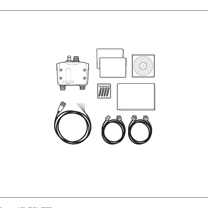
Figure 1 shows the items included with your AIS antenna splitter purchase. The following
sections give a brief overview of each item. Please ensure all items are present and if any of the
items are not present contact your dealer.
Figure 1 Items included with the product
• Quick start guide
The quick start guide gives a handy one page reference for the installation process.
• Product manual
The product manual is this document and should be read thoroughly prior to any attempt to install
or use the AIS antenna splitter.
Page 4
Page 8

About your AIS antenna splitter
•CD
The CD contains this user manual in other languages
• VHF radio connection cable
This cable is used to connect a VHF radio to the AIS antenna splitter. The cable has PL259
connectors at either end and requires a SO239 connector on the VHF radio. If your VHF radio
does not have a SO239 connector please contact your dealer for details of suitable adaptors.
• AIS transceiver connection cable
This cable is used to connect an AIS transceiver to the AIS antenna splitter. The cable has a
BNC connector at one end (for connection to the AIS antenna splitter) and a PL259 connection at
the opposite end (for connection to an AIS transceiver with an SO239 VHF connector). If your
AIS transceiver does not use an SO239 connector please contact your dealer for details of
suitable adaptors.
• AIS antenna splitter unit
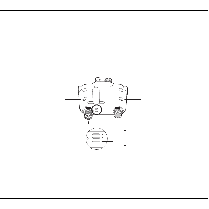
Figure 2 shows an overview of the AIS antenna splitter unit.
The AIS antenna splitter has a number of indicators which provide information to the user about
the status of the AIS antenna splitter. Please refer to section 4 for more details of the indicator
functions.
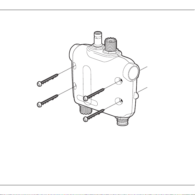
The AIS antenna splitter mounting holes are located as shown in Figure 2. Please refer to section 3.2
for details of how to mount the AIS antenna splitter.
• Power and FM cable
The power and FM cable connects to the AIS antenna splitter and enables connection to power
and an FM radio antenna input.
Page 5
Page 9
About your AIS antenna splitter
VHF radio connection
Power and FM
AIS transceiver connection
VHF antenna connection
Mounting
holes
Mounting
holes
Green
Amber
Amber
Indicator
lights
Electrical connections
The AIS antenna splitter has the following electrical connections as shown in Figure 2.
• Power supply
• VHF antenna connector
• VHF radio connector
• AIS transceiver connector
• FM radio connector
Figure 2 AIS antenna splitter overview
Page 6
Page 10
Installation
VHF antenna
Power in
VHF radio
NMEA 2000
GPS antenna
AIS Class B
transceiver
AIS antenna
splitter
NMEA0183 device
Switch
Power in
Optional PC
Chartplotter
FM radio (optional)
3 Installation
3.1 Preparing for installation
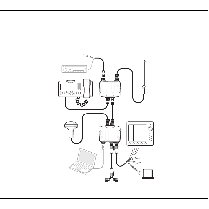
Figure 3 shows a typical installation configuration for the AIS antenna splitter. Please take the
time to familiarise yourself with the system elements and their connections prior to attempting
installation.
Figure 3 Typical installation configuration
Page 7
Page 11

Installation
In addition to the items provided with your AIS antenna splitter the following items will be required
for installation:
VHF antenna
Connection to a suitable VHF antenna will be required for the AIS antenna splitter to operate.
A standard marine band VHF antenna such as that used with VHF voice radios will be sufficient.
Please take note of the warnings in section 1 regarding the use of antennas.
VHF radio
If you have an existing VHF voice radio connected directly to a VHF antenna, you can disconnect
the VHF radio from the VHF antenna and connect them both to the relevant connectors on the
AIS antenna splitter.
AIS transceiver
If you have an existing AIS transceiver connected directly to a VHF antenna, you can disconnect
the AIS transceiver from the VHF antenna and connect them both to the relevant connectors on
the AIS antenna splitter.
It is necessary to connect the VHF antenna, VHF radio and AIS transceiver for the antenna
splitter to function correctly.
FM radio
The AIS antenna splitter also provides connections for the antenna of an FM broadcast radio
receiver. Connection of an FM radio is optional.
Power cable
The AIS antenna splitter is supplied with a two meter long power cable. If you require longer
cables to reach your power supply please ensure the cables are capable of carrying currents of
up to 200mA on average. Means of connecting the cables together will also be required. The use
of Scotchlok
TM
connectors is recommended for this purpose.
Page 8
Page 12

Installation
3.2 Installation procedures
Before beginning installation of your AIS antenna splitter, please ensure you have the necessary
additional items as detailed in section 3.1. It is strongly recommended that you read all of the
instructions in this manual prior to installation.
If after reading this manual you are unsure about any element of the installation process please
contact your dealer for advice.
The following sections explain the installation process step by step for each of the main elements
of the system.
Step 1 - Installing the AIS antenna splitter
Please note the following guidelines when selecting a location for your AIS antenna splitter:
• The AIS antenna splitter must be fitted in a location where it is at least 0.5m from a compass
or any magnetic device.
• There should be adequate space around the AIS antenna splitter for routing of cables. See
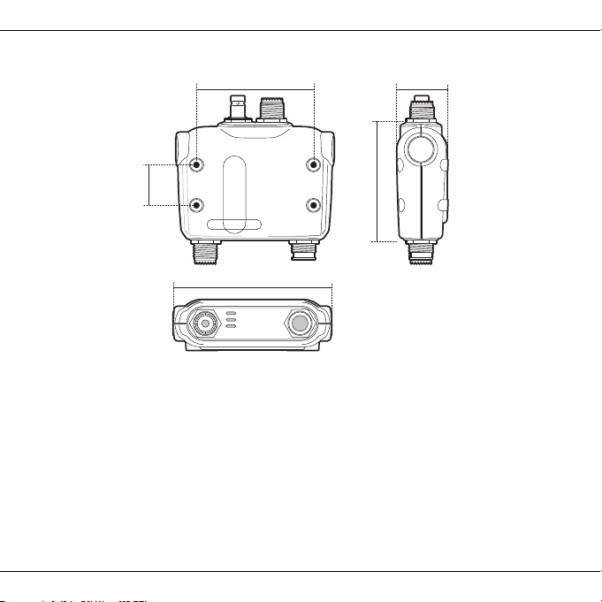
Figure 4 for details of the AIS antenna splitter dimensions.
• The ambient temperature around the AIS antenna splitter should be maintained between
-25°C and +55°C.
• The AIS antenna splitter should not be located in a flammable or hazardous atmosphere such
as in an engine room or near to fuel tanks.
• The AIS antenna splitter is not waterproof and must not be submerged or exposed to spray.
• It is acceptable to mount the AIS antenna splitter either vertically or horizontally.
• It is recommended that the AIS antenna splitter is installed in a 'below decks' environment.
• The AIS antenna splitter should be mounted in a location where the indicators are readily
visible as these provide important information on the status of the AIS antenna splitter.
Page 9
Page 13
Installation
116 mm
30 mm
87 mm
87.2 mm
37 mm
Figure 4 AIS antenna splitter dimensions
Page 10
Page 14
Installation
Figure 5 AIS antenna splitter mounting
Page 11
Page 15
Installation
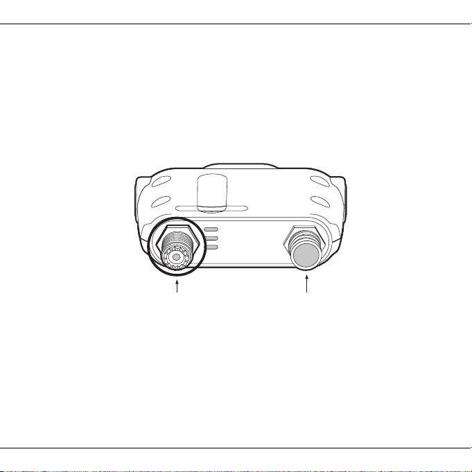
Power and FMVHF antenna connection
Step 2 - Connecting the VHF antenna
Route the cable from the VHF antenna to the AIS antenna splitter and connect to the VHF
antenna connector on the AIS antenna splitter as shown in Figure 6.
A standard marine band VHF antenna or AIS antenna should be used with the AIS antenna
splitter. The connector type on the AIS antenna splitter is SO239. Your chosen VHF antenna
requires a PL259 connector to mate with this. If your VHF antenna does not use this type of
connector please contact your dealer for details of available adaptors.
Figure 6 Position of the VHF antenna connector
Page 12
Page 16
Installation
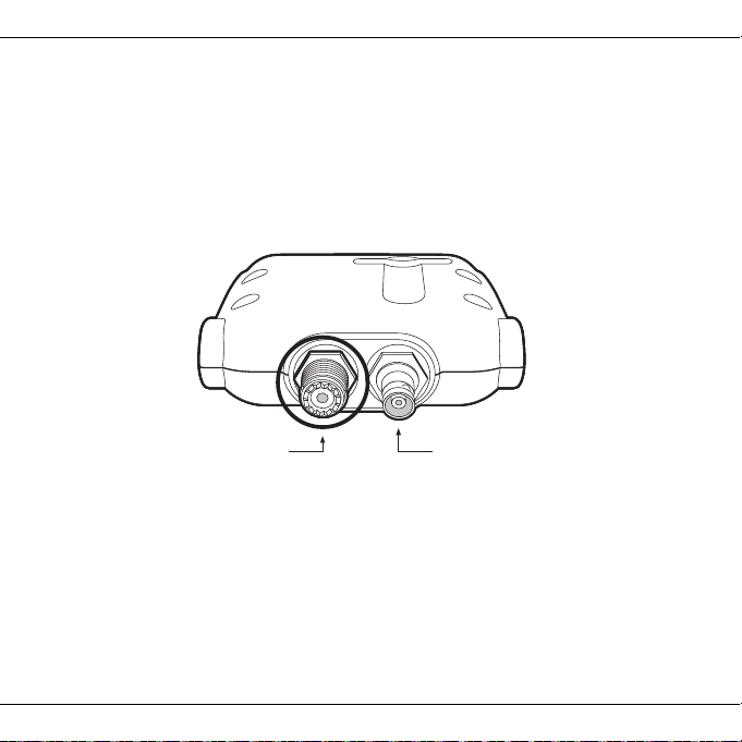
AIS transceiver connectionVHF radio connection
Step 3 - Connecting the VHF radio
Using the VHF radio accessory cable provided with this product, route the cable from the VHF
radio to the AIS antenna splitter and connect to the VHF radio connector on the AIS antenna
splitter as shown in Figure 7. If the cable supplied is not long enough please contact your dealer
for details of suitable extension cables.
A standard marine band VHF voice radio should be used with this AIS antenna splitter. The
antenna splitter is DSC compatible.
Figure 7 Position of the VHF radio connector
Page 13
Page 17
Installation
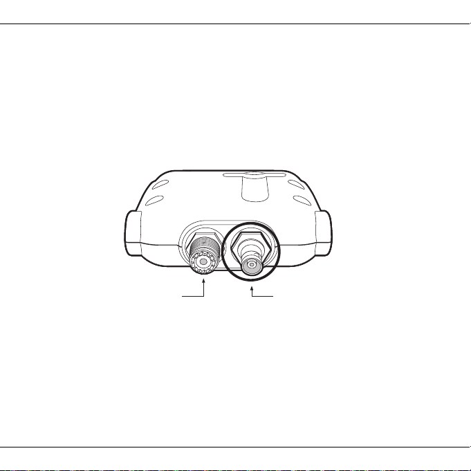
AIS transceiver connectionVHF radio connection
Step 4 - Connecting the AIS transceiver
Using the AIS transceiver accessory cable provided with this product, route the cable from the
AIS transceiver to the AIS antenna splitter and connect to the AIS transceiver connector on the
AIS antenna splitter as shown in Figure 8. If the cable supplied is not long enough please contact
your dealer for details of suitable extension cables.
A fully approved marine AIS Class B transceiver or AIS receiver should be used with this AIS
antenna splitter and requires a SO239 VHF antenna connector to connect to the AIS antenna
splitter using the supplied accessory cable.
Figure 8 Position of the AIS transceiver connector
Page 14
Page 18
Installation
FM output
FM ground
Green
White
Blue
Power in +
Power in –
Red
Black
FM ground
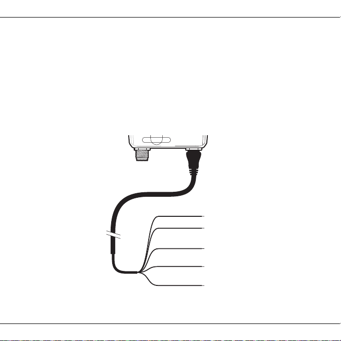
Step 5 - Connecting the power supply and optional FM output
The AIS antenna splitter requires a 12V or 24V power supply typically provided by the vessel's
battery. It is recommended that crimped and soldered lugs are used to connect the AIS antenna
splitter to the power source. It is recommended that the power supply is connected via a suitable
circuit breaker and/or 1A fuse block.
1. Connect the red wire to the power supply positive terminal.
2. Connect the black wire to the supply negative terminal.
3. Connect the White wire to the FM radio antenna input.
4. Join the Blue and Green wires and connect to the FM radio antenna ground.
Figure 9 Connecting the power supply and optional FM output
Page 15
Page 19
Operation
It is not possible for both connected devices to transmit simultaneously using a
single VHF antenna. Whilst you are talking on your VHF radio no AIS position
reports will be transmitted.
!
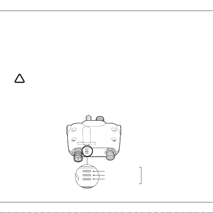
Green (Power)
Amber (VHF transmit)
Amber (AIS transmit)
Indicator
lights
4 Operation
Operation of the AIS antenna splitter is automatic and requires no user intervention.
During operation the antenna splitter will share signals received at your VHF antenna with both
the AIS transceiver and the VHF radio.
When either the AIS transceiver or VHF radio transmits, the AIS antenna splitter will
automatically sense the transmission and route the signal to the antenna.
In the event that both the VHF radio and AIS transceiver are transmitting at the same time, the
AIS antenna splitter will give priority to the VHF radio.
4.1 Indicator functions
The AIS antenna splitter includes three coloured indicators as shown in Figure 10. The state of
the indicators provides information regarding the status of the AIS antenna splitter.
Figure 10 Indicator location on the AIS antenna splitter unit
Page 16
Page 20

Operation
The indicators provide the following functions:
• Power - this indicator is illuminated whilst the unit is powered
• TX VHF - this indicator flashes to indicate VHF radio transmissions
• TX AIS - this indicator flashes to indicate AIS transmissions
Note that both the TX AIS and TX VHF LEDs may illuminate when the AIS antenna splitter is
used with some brands of VHF radio at the high output power (25W) setting. This is normal
behavior and does not indicate a fault.
Page 17
Page 21

Troubleshooting
5 Troubleshooting
Issue Possible cause and remedy
Power indicator not illuminated Check power supply connections and fuse or circuit breaker
Check polarity of power supply connections
Check power supply voltage
'VHF' indicator does not
illuminate when
VHF Radiotelephone is
transmitting
'AIS' indicator does not
illuminate when
AIS transceiver is transmitting
Clicks or pops are heard from a
connected FM broadcast
receiver
VHF or AIS transmission range
is reduced
Both the ‘AIS’ and ‘VHF’
indicators illuminate when the
VHF radio is transmitting
If the guidance given in the table above does not rectify the problem you are experiencing please
contact your dealer for further assistance.
Check the antenna output of the VHF Radiotelephone is
connected to the antenna splitter input labelled 'VHF'
Check the antenna output of the AIS transceiver is
connected to the antenna splitter input labelled 'AIS'
This is normal and may occur during VHF or AIS
transmission
A small reduction in transmission range is normal and due
to the insertion loss of the antenna splitter
This is normal operation with some brands of VHF radio and
not a fault. Function of the antenna splitter is unaffected
Page 18
Page 22

Specifications
6 Specifications
Parameter Value
Dimensions 140 x 100 x 42 mm (L x W x H)
Weight 250g
Voltage supply DC 9.6 to 31.2V
Current consumption <150mA at 12VDC
VHF and AIS frequency range 156MHz to 163MHz
Insertion loss AIS & VHF receive
paths 0dB
Insertion loss AIS & VHF transmit
paths
Max input power, AIS port 12.5W
Max input power, VHF port 25W
Min input power, VHF port 100mW
AIS, VHF and Antenna port
impedance
FM port impedance 75 Ohms
Switching time, receive to AIS transmit <10 us
Switching time, receive to VHF
transmit
Operating temperature: -10ºC to +55ºC
0dB
<1dB
50 Ohms
<10us
Page 19
Page 23

Page 24

High Performance Maritime Products
www.em-trak.com
The per formance of the S100 may be seriously impaired if not installed as instructed in the
user manual, or due to other factors such as weather and or nearby transmitting devices.
em-trak reserves the right to update and change these specications at any time and
without notice.
Head O fce:
em-trak Marine Electronics Limited
Forum 3,
Parkw ay, Solent Business Park,
Whiteley, Fareham,
Southa mpton PO15 7FH
United Kingdom
T +44 (0)1489 611662 | F + 44 (0)148 9 611612
[email protected]
Regional Ofce:
em-trak Marine Electronics Limited
470 Atlanti c Avenue,
4th oor,
Boston M A 02210
USA
 Loading...