

Page 1

B900 Series
Class B I AIS Transceiver User manual
Page 2

Thank you for purchasing this Class B AIS transceiver.
This product has been engineered to offer you the highest level of
performance and durability and we hope that it will provide many years of
reliable service. We constantly strive to achieve the highest possible quality
standards, should you encounter any problems with this product, please
contact your dealer or [email protected] who will be pleased to offer any
assistance you require.
Page 3

Table of contents
Table of contents
1 Regulatory notices......................................... 4
1.1 Safety warnings ............................................................................. 4
1.2 General notices.............................................................................. 4
2 About your AIS transceiver........................... 9
2.1 Overview ........................................................................................ 9
2.2 B900 Product range ....................................................................... 11
2.3 What's in the box? ......................................................................... 12
2.4 Support and warranty..................................................................... 12
2.5 Configuration tools ......................................................................... 13
3 Installation ...................................................... 14
3.1 Summary........................................................................................ 14
3.2 Antennas........................................................................................ 16
3.3 Power............................................................................................. 18
3.4 Location and fixing of the transceiver ............................................ 21
3.5 Configuration.................................................................................. 24
3.6 Connectivity ................................................................................... 30
4 Operation ........................................................ 35
4.1 LED indicators................................................................................ 35
4.2 Silent mode .................................................................................... 37
4.3 Voyage data recorder .................................................................... 38
4.4 PGN table ...................................................................................... 39
5 Troubleshooting............................................. 42
6 Specifications................................................. 44
7 About AIS........................................................ 46
7.1 About AIS....................................................................................... 46
Page 1
Page 4

Table of contents
7.2 Static and dynamic vessel data...................................................... 47
8 List of abbreviations...................................... 48
Page 2
Page 5

List of figures and tables
List of figures and tables
Figure 1 AIS transceiver overview ..................................................... 9
Figure 2 FLEXI-FIT bracket ............................................................... 10
Table 1 Product variants................................................................... 11
Figure 3 Items included with the product ........................................... 12
Figure 4 Typical installation configuration.......................................... 14
Figure 5 Position of the VHF antenna connector ............................... 16
Figure 6 Position of the GPS antenna connector............................... 17
Figure 7 Power and data cable connections ...................................... 18
Table 2 Colour coding of wires in the accessory cable..................... 19
Figure 8 Connecting the power supply .............................................. 20
Figure 9 AIS transceiver dimensions ................................................. 22
Figure 10 FLEXI-FIT bracket ............................................................... 22
Figure 11 AIS transceiver mounting..................................................... 23
Figure 12 Configuration using your PC................................................ 24
Figure 13 Typical mobile devices for WiFi & Bluetooth connection .....27
Figure 14 Configuration using your smartphone.................................. 28
Figure 15 NMEA 2000 network connection ......................................... 30
Figure 16 Connecting to your chartplotter............................................ 31
Figure 17 Connecting to your NMEA 0183 sensor .............................. 32
Figure 18 Connecting to your PC......................................................... 33
Figure 19 LED indicator location on the AIS transceiver unit............... 35
Table 3 LED indicator functions........................................................ 36
Figure 20 Connecting an external switch............................................. 37
Table 4 NMEA 2000 PGN List .......................................................... 41
Table 5 Troubleshooting ................................................................... 43
Table 6 Specifications....................................................................... 45
Figure 21 The AIS network .................................................................. 47
Page 3
Page 6
Regulatory notices
When reading this manual please pay attention to warnings
marked with the warning triangle shown on the left. These are
important messages for safety, installation and usage of the
product.
!
This equipment must be installed in accordance with the instructions
provided in this manual.
!
This AIS transceiver is an aid to navigation and must not be
relied upon to provide accurate navigation information. AIS is
not a replacement for vigilant human lookouts and other
navigation aids such as RADAR. The performance of the
transceiver may be seriously impaired if not installed as
instructed in the user manual, or due to other factors such
as weather and or nearby transmitting devices. Compatibility
with other systems may vary and is reliant on the third party
systems recognising the standard outputs from the transceiver.
The manufacturer reserves the right to update and change
these specifications at any time and without notice.
!
Do not install this equipment in a flammable atmosphere such
as in an engine room or near to fuel tanks.
!
1 Regulatory notices
1.1 Safety warnings
1.2 General notices
1.2.1 Position source
All marine Automatic Identification System (AIS) transceivers utilise a satellite
based location system, which is referred to as Global Navigation Satellite
System (GNSS). This includes Global Positioning System (GPS),
Globalnaya Navigazionnaya Sputnikovaya Sistema (GLONASS), Galileo,
and BeiDou.
Page 4
Page 7

Regulatory notices
The accuracy of a GPS position fix is variable and is affected by factors such
as the antenna positioning, how many satellites are used to determine a
position and how long satellite information has been received for.
1.2.2 Compass safe distance
The compass safe distance of this unit is 0.2m or greater for 0.3° deviation.
1.2.3 RF emissions notice
Caution: The AIS transceiver generates and radiates radio frequency
electromagnetic energy. This equipment must be installed and operated
according to the instructions contained in this manual. Failure to do so can
result in personal injury and / or AIS transceiver malfunction.
Caution: Never operate the AIS transceiver unless it is connected to a VHF
antenna.
To maximise performance and minimise human exposure to radio frequency
electromagnetic energy you must make sure that the antenna is mounted at
least 1.5 metres away from the AIS transceiver and is connected to the AIS
transceiver before power is applied. The system has a Maximum Permissible
Exposure (MPE) radius of 1.5m. This has been determined assuming the
maximum power of the AIS transceiver and using antennas with a maximum
gain of 3dBi.The antenna should be mounted 3.5m above the deck in order to
meet RF exposure requirements. Higher gain antennas will require a greater
MPE radius. Do not operate the unit when anyone is within the MPE radius of
the antenna (unless they are shielded from the antenna field by a grounded
metallic barrier). The antenna should not be co-located or operated in
conjunction with any other transmitting antenna. The required antenna
impedance is 50 Ohms.
1.2.4 Disposal of this product and packaging
Please dispose of the AIS transceiver in accordance with the European
WEEE Directive or with the applicable local regulations for disposal of
electrical equipment.
Page 5
Page 8

Regulatory notices
Every effort has been made to ensure the packaging for this product is
recyclable. Please dispose of the packaging in an environmentally friendly
manner.
1.2.5 Accuracy of this manual
The AIS transceiver may be upgraded from time to time and future versions
of the AIS transceiver may therefore not correspond exactly with this manual.
Information contained in this manual is liable to change without notice. The
manufacturer of this product disclaims any liability for consequences arising
from omissions or inaccuracies in this manual and any other documentation
provided with this product.
1.2.6 Radio Equipment Directive
The manufacturer of this product declares that this product is in compliance
with the essential requirements and other provisions of the Radio Equipment
Directive 2014/53/EU and as such displays the CE mark. The RED
declaration of conformity is provided as part of this documentation pack. The
declaration of conformity is provided with the product document pack.
1.2.7 FCC notice
This equipment has been tested and found to comply with the limits for a
class B digital device, pursuant to part 15 of the FCC Rules. These limits are
designed to provide reasonable protection against harmful interference in a
residential installation. This equipment generates, uses and can radiate radio
frequency energy and, if not installed and used in accordance with the
instructions, may cause harmful interference to radio communications.
This device complies with part 15 of the FCC Rules. Operation is subject to
the following two conditions: (1) This device may not cause harmful
interference, and (2) this device must accept any interference received,
including interference that may cause undesired operation.
Page 6
Page 9

Regulatory notices
WARNING: It is a violation of the rules of the Federal
Communications Commission to input an MMSI that has not
been properly assigned to the end user, or to otherwise input
any inaccurate data in this device.
!
In the United States of America, the MMSI and static data must
only be entered by a competent installer. The end user of the
equipment is not authorised to enter their own vessel data.
!
Changes or modifications not expressly approved by the party responsible for
compliance could void the user's authority to operate the equipment.
1.2.8 Important information for US customers
US CUSTOMERS ONLY: In the USA it is illegal for an end user to configure
their own AIS with their vessel data. To do so is a violation of the rules of the
United States Coast Guard (USCG). This must be done by a competent
installer, such as em-trak, an em-trak dealer or competent marine electronics
professional. If your transceiver has not been pre-configured for you please
refer to your dealer or contact [email protected] for advice on how to
have the transceiver configured legally. If purchasing direct from em-trak
online we can configure it for you and dispatch it pre-configured at no extra
cost, if you are purchasing from one of our dealers, then they will do it for you.
1.2.9 Industry Canada notice
This device complies with Industry Canada license-exempt RSS standard(s).
Operation is subject to the following two conditions:
1. This device may not cause interference, and
2. This device must accept any interference, including interference that may
cause undesired operation of the device.
This Class B digital apparatus complies with Canadian ICES-003.
Page 7
Page 10

Regulatory notices
Le présent appareil est conforme aux CNR d'Industrie Canada applicables
aux appareils radio exempts de licence. L'exploitation est autorisée aux deux
conditions suivantes:
1. L'appareil ne doit pas produire de brouillage, et
2. L'utilisateur de l'appareil doit accepter tout brouillage radioélectrique subi,
même si le brouillage est susceptible d'en compromettre le Fonctionnement.
Cet appareil numérique de la classe B est conforme à la norme NMB-003 du
Canada.
Page 8
Page 11
About your AIS transceiver
NMEA 2000Power and data
(Only applicable for
B923, B924, B953 and B954)
VHF antenna*GPS antenna
VHF radio
Mounting bracket
Amber
No Tx
indicator Lights
Blue
Silent
Red
Error
Amber
No Tx
Green
Power
* GPS receiver & antenna supports: GPS, GLONASS, Galileo and BeiDou
150 mm
115 mm
43 mm
2 About your AIS transceiver
2.1 Overview
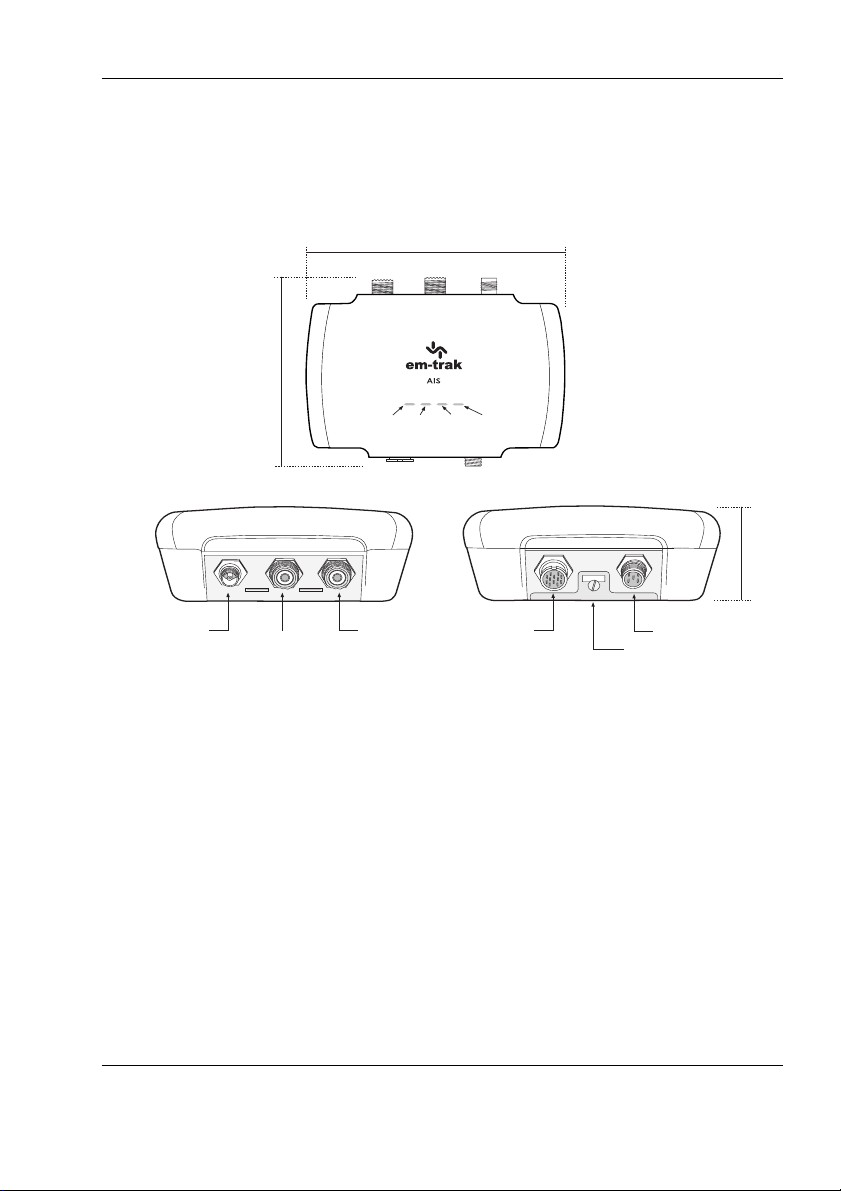
Figure 1 AIS transceiver overview
Page 9
Page 12
About your AIS transceiver
83.4 mm
60.3 mm 10 mm
71 mm
150 mm8.5 mm
3.4 mm DIA
60.3 mm
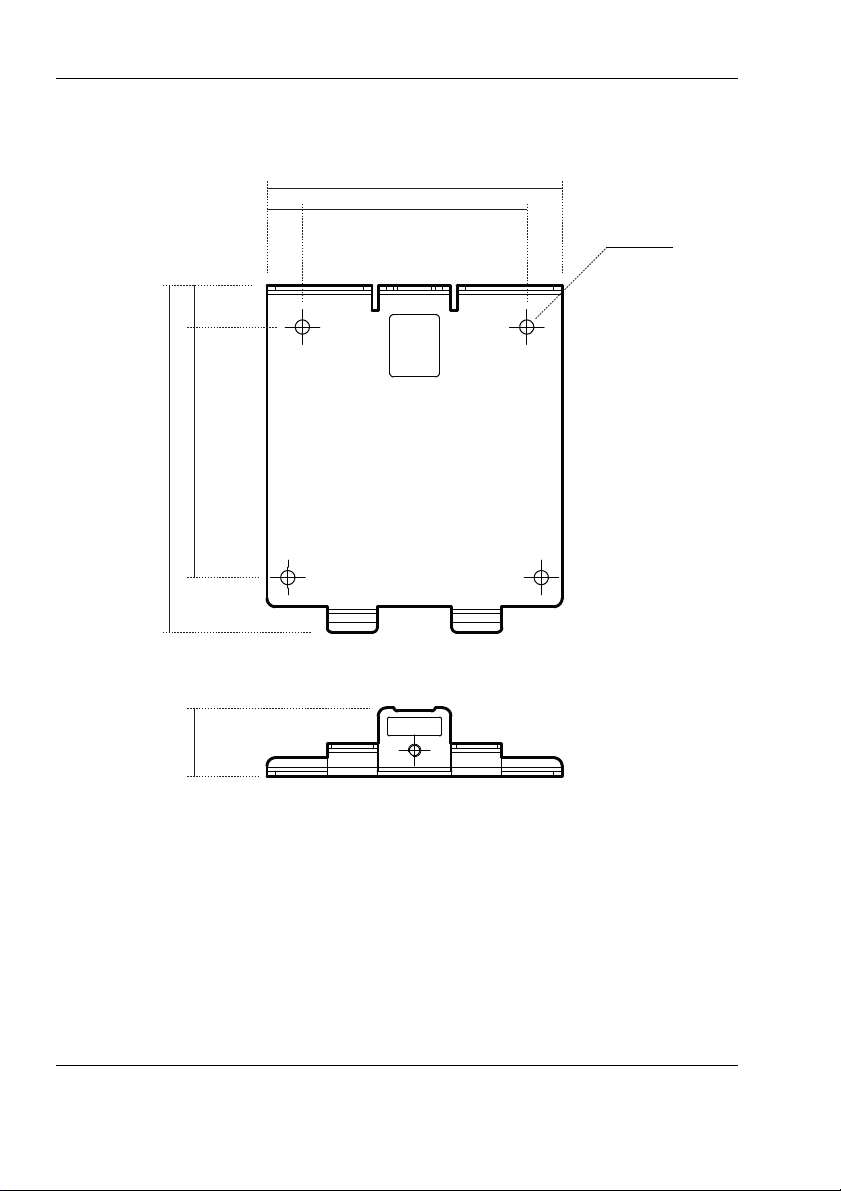
Figure 2 FLEXI-FIT bracket
Page 10
Page 13

About your AIS transceiver
(IPx6 and IPx7)
Yes Yes Yes Yes Yes Yes Yes Yes
FLEXI-FIT bracket Yes Yes Yes Yes Yes Yes Yes Yes
Yes Yes Yes Yes Yes Yes Yes Yes
No No Yes Yes No No Yes Yes
WiFi & Bluetooth No Yes No Yes No Yes No Yes
r
No Yes No Yes No Yes No Yes
2.2 B900 Product range
The B900 Series provides multiple feature options. The variants are listed in
Table 3 and the main features are detailed below.
AIS Class B
transm iss ion type2WCSTDMA2WCSTDMA2WCSTDMA2WCSTDMA5WSOTDMA5WSOTDMA5WSOTDMA5WSOTDMA
Water & weatherproof
Integrated GNSS
receiver & antenna
Integrated VHF
antenna splitter
Voyage Data Recorde
NMEA 2000,
NMEA 0183 & USB
Table 1 Product variants
2.2.1 Main features:
● Integrated WiFi & Bluetooth so you can connect wirelessly to all your
devices. Only applicable to B922/B924/B952/B954.
● Integrated VHF antenna splitter so you can use your existing VHF
radio antenna. Only applicable to B923/B924/B953/B954.
● Integrated high performance GPS receiver and antenna so that an
external one is optional.
● FLEXI-FIT™ bracket to make installation on any boat simple, safe
and secure.
● IPx7 tested and certified for complete water submersion and IPx6
tested and certified for high pressure spray. The B900 Series is able
to be installed and operated permanently outdoors in a fully exposed
location or in a location where it will be exposed to extreme hot or
cold temperatures, damp, salt air and water.
● NMEA 2000, NMEA 0183 & USB so you can connect to any chart
plotter, sensor, PC or laptop.
B921 B922 B923 B924 B951 B952 B953 B954
Yes Yes Yes Yes Yes Yes Yes Yes
Page 11
Page 14
About your AIS transceiver
Documentation
pack
Class B AIS transceiver
2 metre
Power and
data cable
FLEXI-FIT
™
bracket
Fixings
kit
1 metre
VHF radio
connection cable
(only applicable
to B923 / B924 /
B953 / B954)
2.3 What's in the box?
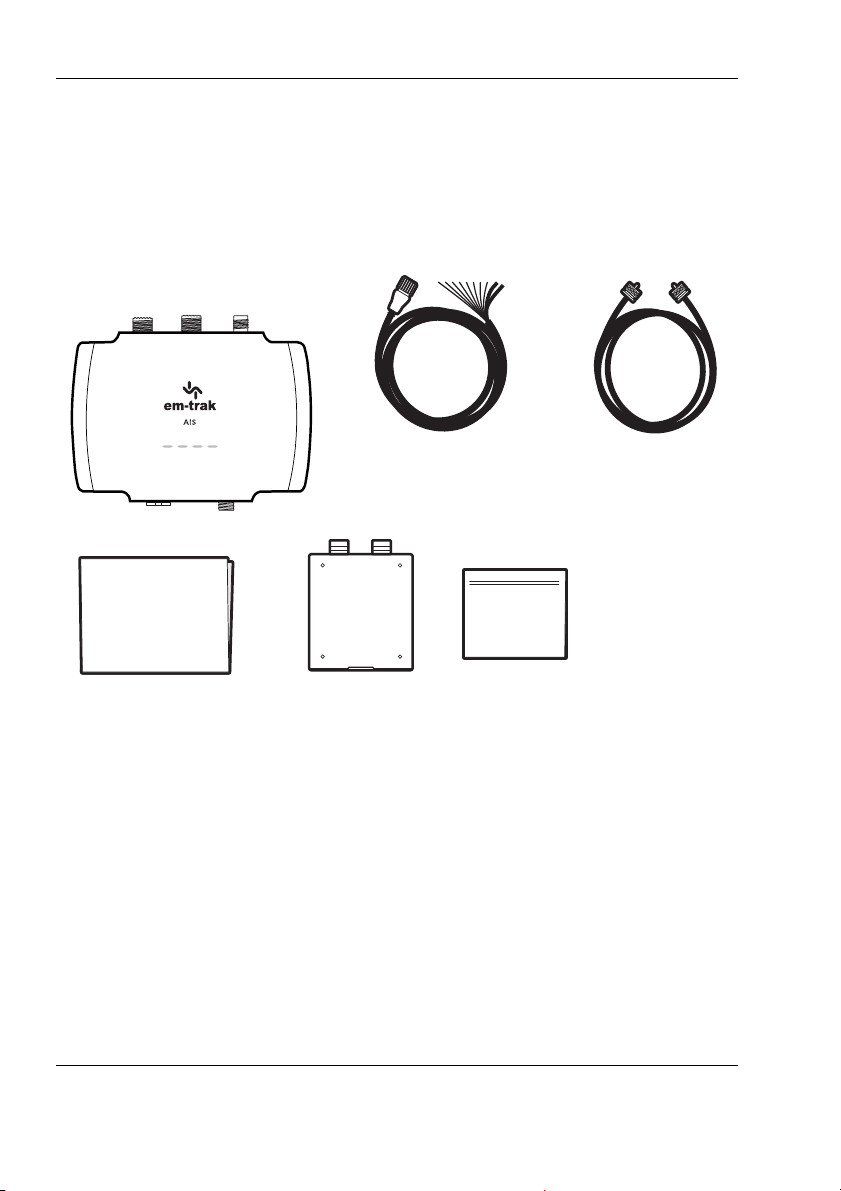
Figure 3 shows the items included with your B900 Series purchase. If any of
the items are not present please contact your dealer or support@emtrak.com.
Figure 3 Items included with the product
2.4 Support and warranty
With em-trak you can buy with confidence. If you are unhappy with your new
product for any reason, within two days of receipt and subject to the product
and packaging being complete and undamaged, you may return it to us for a
full refund. We are sorry, but we cannot accept the return of any product if you
have not advised us in writing within 48 hours of receiving your em-trak
product, or if it has been used and or damaged or if any of the package is
incomplete. All em-trak products benefit from our three year global warranty.
In the unlikely event of a problem, please contact our Customer Support
department (24/7) at [email protected] and one of our experts will work
Page 12
Page 15

About your AIS transceiver
with you to instantly resolve your issue or arrange the repair or replacement
of your em-trak product. The warranty is invalidated if the product has been
incorrectly used, damaged or tampered.
We recommend visiting www.em-trak.com/support to access the product
FAQs, and to download user manuals and documentation.
2.5 Configuration tools
Your AIS transceiver will need to be configured with your vessel details before
it will start transmitting and working correctly. To do that you will need to
download the em-trak configuration tool on to your smartphone or PC,
whichever is most convenient for you.
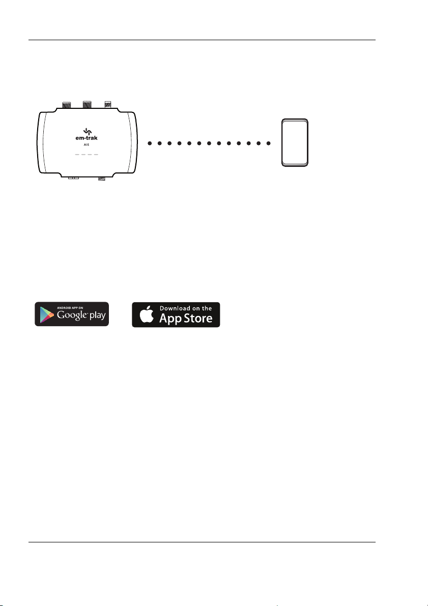
If you wish to use your smartphone, you will need to download CONNECTAIS from Google Play or the Apple App Store.
.
Once downloaded you can configure the B922/B924/B952/B954 wirelessly
using either Bluetooth or WiFi connectivity. More detail on CONNECT-AIS
and the configuration process can be found in Section 3.5.2.
If you wish to use your PC or laptop, you will need to download proAIS2 from
www.em-trak.com/installation.
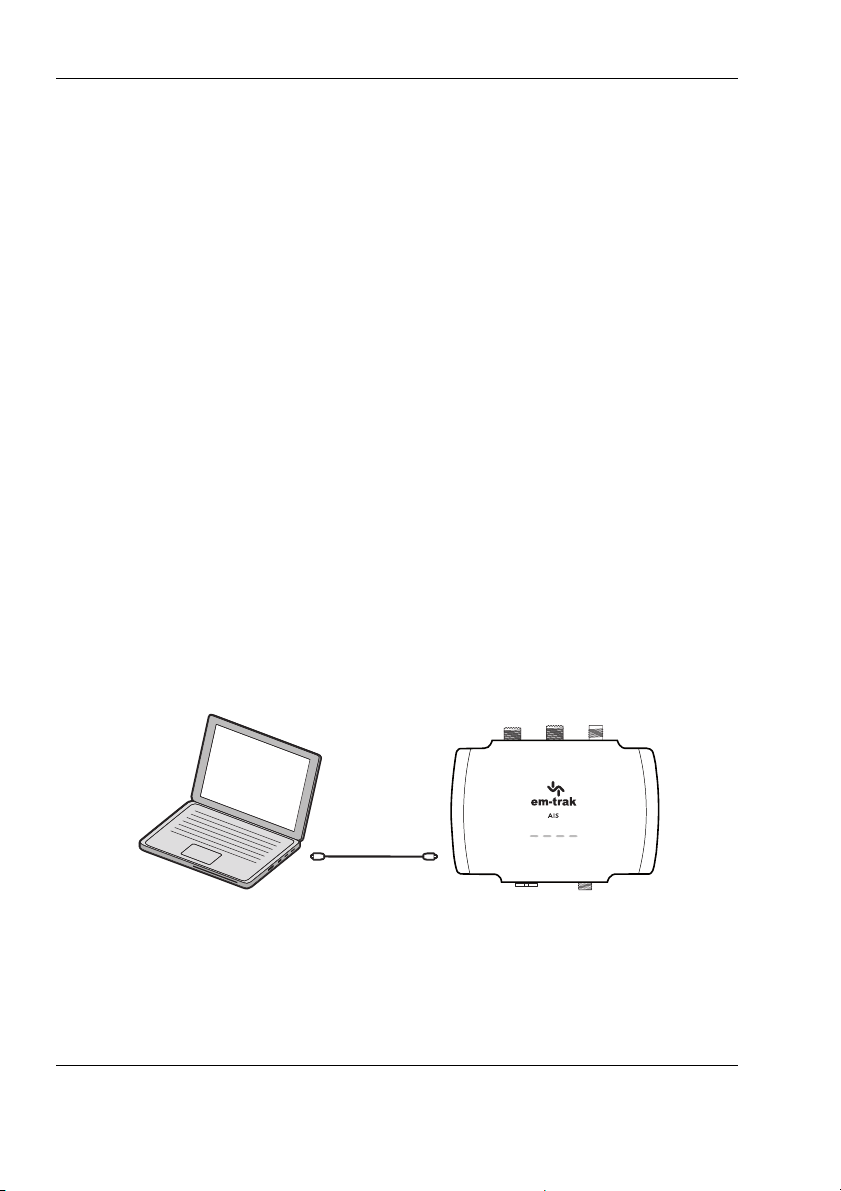
Once downloaded you can configure any variant using a micro USB cable
(not supplied). More detail on proAIS2 and the configuration process can be
found in Section 3.5.2.
Page 13
Page 16
Installation
Power in
Switch
NMEA 2000
Chartplotter
VHF antenna
VHF radio
USB
NMEA 0183 device
GPS antenna
(Optional)
AIS Class B
transceiver
(Only applicable to B923, B924, B953 and B954)
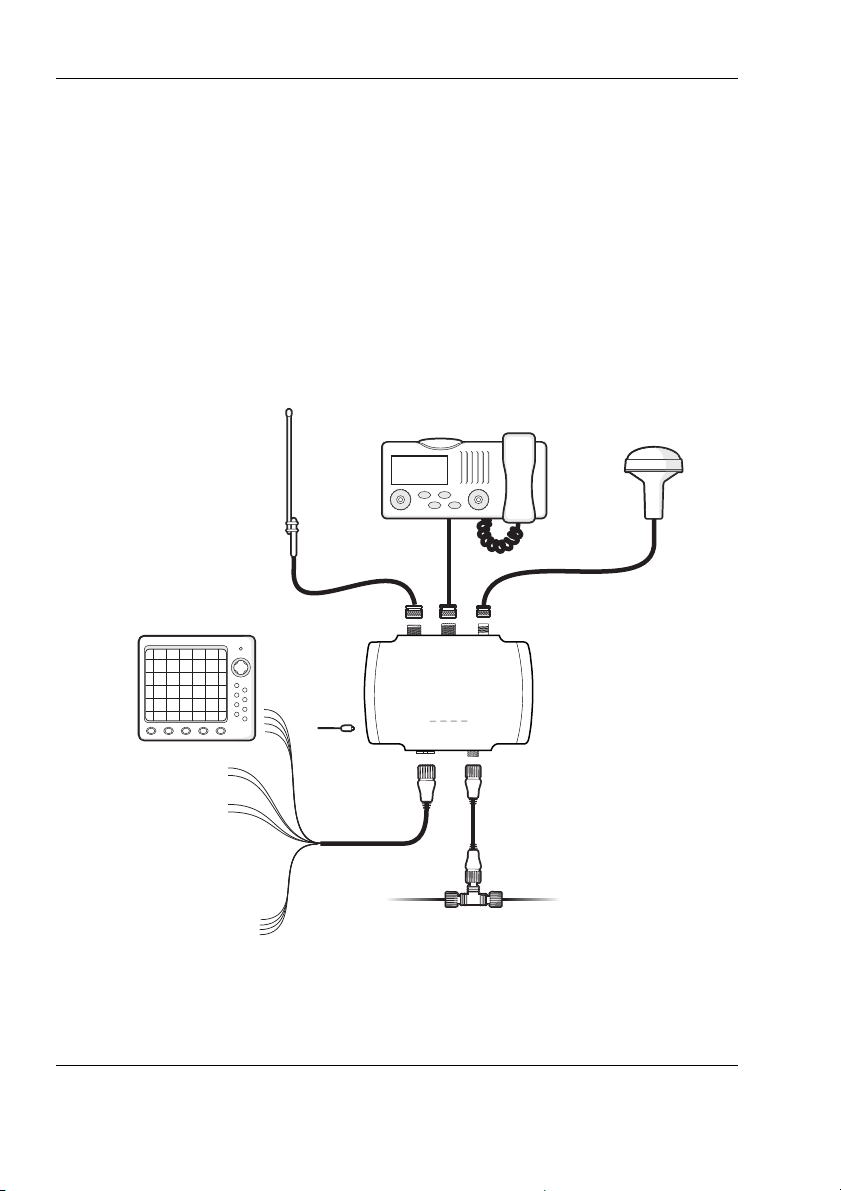
3 Installation
3.1 Summary
Before beginning installation of your transceiver, please ensure you have any
necessary additional items as detailed below. It is strongly recommended that
you read all of the instructions in this manual prior to installation. If after
reading this manual you are unsure about any element of the installation
process please contact your dealer or [email protected] for advice.
Figure 4 Typical installation configuration
Page 14
Page 17

Installation
In addition to the items supplied, the following may also be required for your
installation:
● VHF antenna and cable - this is required for your transceiver to
receive and transmit. A variant with an integrated splitter (B923/
B924/B953/B954) can use an existing VHF antenna as long as it
covers 159MHz so it will be compatible with both VHF radio
(156MHz) and AIS (162MHz). VHF antenna installation is covered in
more detail in Section 3.2.1. If you need to extend the antenna cable
when connecting to your existing VHF antenna, RG-58 or RG-8X can
be used for short distances. For longer runs we would recommend a
low loss cable like RG-213.
● External GPS antenna - this may be required if your installation
location is deep inside your boat where the Integrated GPS receiver
and antenna will not be able to receive satellite signals. GPS antenna
installation is covered in more detail in Section 3.2.2.
● Power cable - this may be required to extend the length of the 2m
power and data cable that is supplied with your transceiver. If you
require longer cables to reach your power supply, please ensure they
are capable of carrying currents of up to 2.5A peak and 220mA on
average. Connecting the power supply is covered in more detail in
Section 3.3.1.
● Micro USB cable - this is required for connection to a PC or laptop.
USB drivers and the configuration process are covered in more detail
in Section 3.6.4.
● Toggle switch - this can be used to turn on/off silent mode. We would
recommend a latching toggle switch for this application. Installation of
the toggle switch is covered in more detail in Section 4.2. Silent mode
can also be controlled using the configuration tools, proAIS2 and
CONNECT-AIS.
Page 15
Page 18
Installation
VHF antennaVHF radio
(Only applicable to B923, B924, B953 and B954)
3.2 Antennas
3.2.1 VHF antenna:
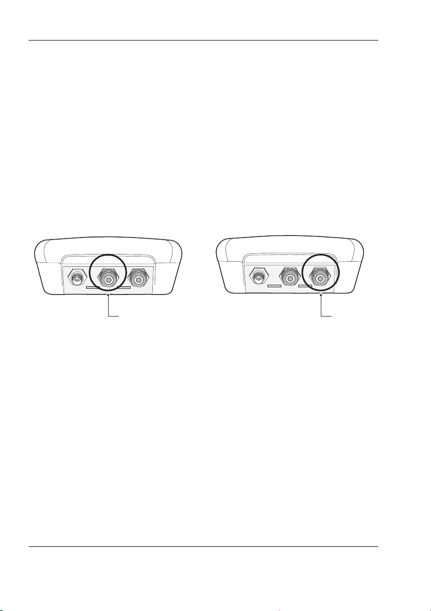
Connection to a suitable VHF antenna will be required for the transceiver to
receive and transmit.
Transceiver variants (B921/B922/B951/B952) do not have an integrated
splitter and will require a dedicated VHF antenna that covers the AIS
channels at 162MHz.
Integrated splitter variants (B923/B924/B953/B954) will require a VHF
antenna covering 159MHz so it will be compatible with both VHF radio
(156MHz) and AIS (162MHz).
Figure 5 Position of the VHF antenna connector
The VHF antenna connector type is SO-239. It requires a PL-259 mating
connector for the antenna.
For optimum performance the VHF antenna should be mounted as high as
possible, and as far away as possible from metal structures, obstructions or
sources of interference. If another transmitting antenna is installed on the
same vessel we would recommend a separation distance of at least 3m.
3.2.2 GPS Antenna:
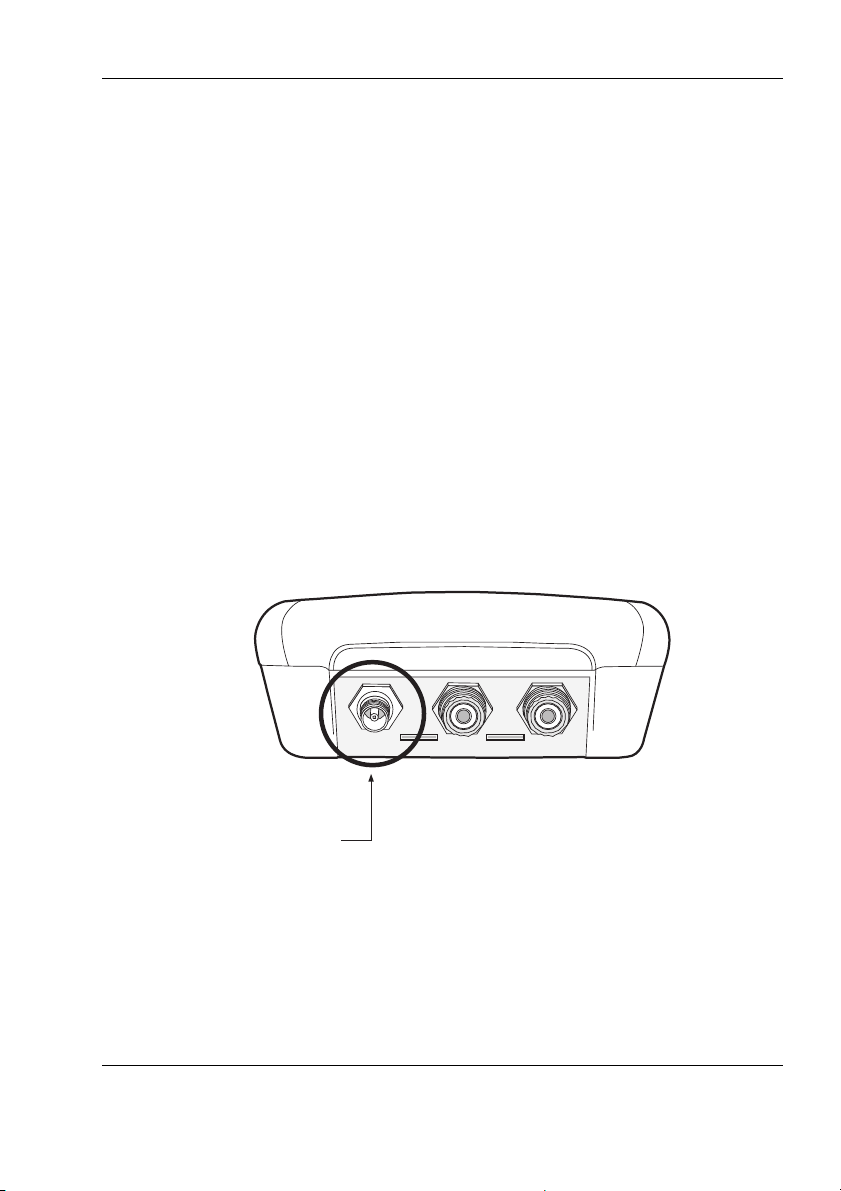
All B900 variants have an integrated high-performance GPS receiver &
antenna, and is compatible with the GPS, GLONASS, Galileo, and BeiDou
satellite navigation systems. A dual GPS mode can be enabled using the
configuration tools, allowing you to combine any two of the above systems.
Page 16
Page 19
Installation
GPS antenna
This will provide a more stable position fix, and also offers redundancy if one
of the satellite systems goes offline. If you install it near a window, under a
fiberglass deck or inside a centre console, you will not require an external
GPS antenna. If your installation location is deep inside your boat where the
GPS antenna will not be able to receive satellite signals you will need an
external GPS antenna. We recommend the em-trak GPS100, which is
available for purchase from www.em-trak.com
Please note the following guidelines when installing an external GPS
antenna.
● You will require a 1" (inch) 14 TPI threaded if you choose to pole
mount the GPS antenna.
● Mounting the external GPS antenna at a low point on the boat will
minimise the effect of pitch and roll on your position.
● Do not mount your antenna in the direct path of a radar or any other
transmitting equipment.
Figure 6 Position of the GPS antenna connector
Page 17
Page 20
Installation
Transmit +
Transmit –
Power in +
Power in –
Switch connection
Switch connection
Receive +
Receive –
Brown
Blue
Light green
Orange
Red
Black
White
Green
Purple
Pink
Grey
Yellow
Transmit +
Transmit –
Receive +
Receive –
NMEA 0183
Port 1
NMEA 0183
Port 2
3.3 Power
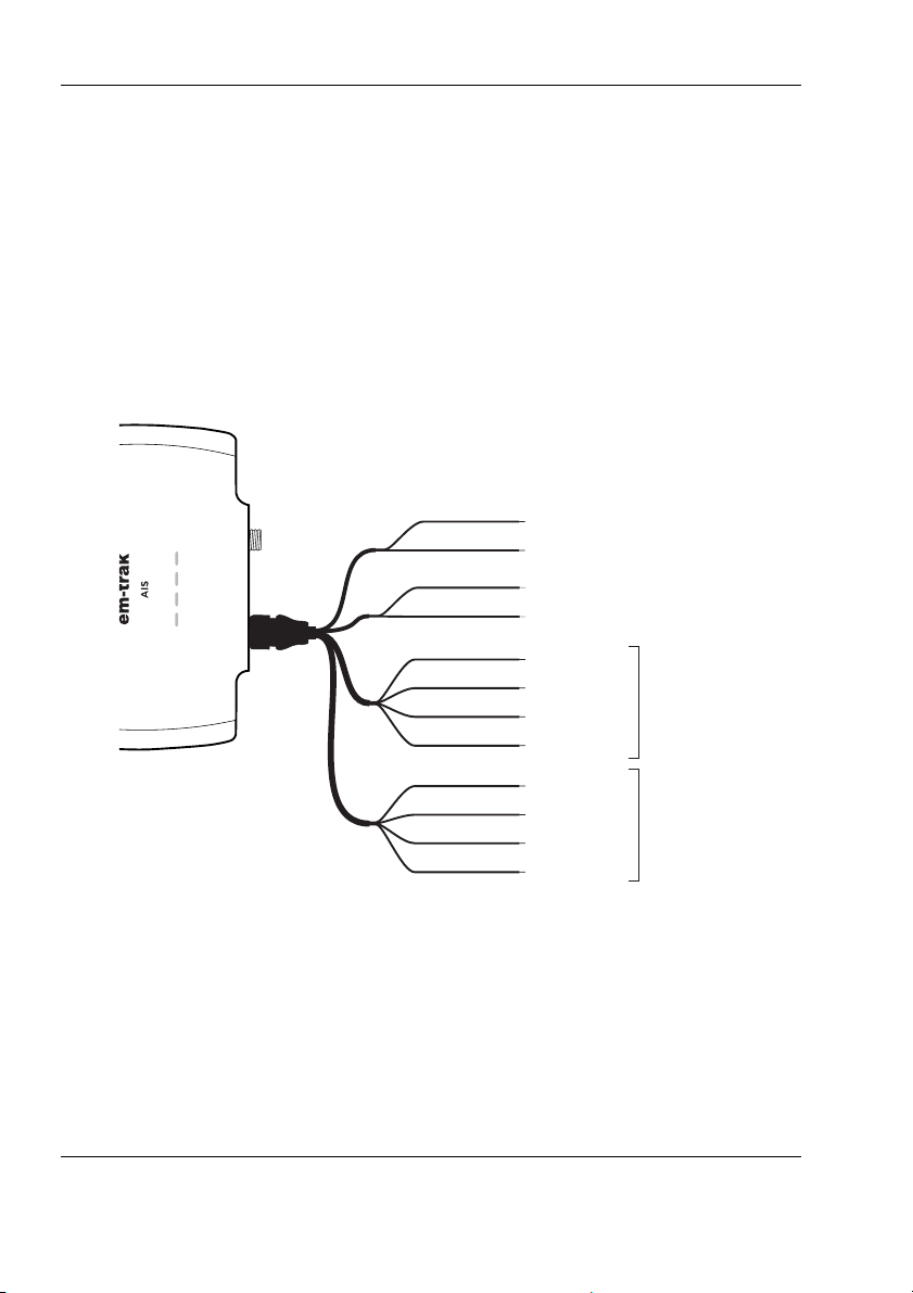
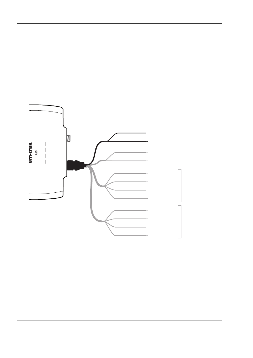
3.3.1 Connecting the power and data cable:
A power and data cable is supplied with the product to provide connections
for power, two NMEA 0183 data ports and the optional silent mode switch.
The cable has a moulded connector at one end which should be connected to
the 12 pin connector on the unit. The other end of the cable has 12 colour
coded bare wires ready for connection.
Figure 7 Power and data cable connections
Page 18
Page 21
Installation
Please check your wiring very carefully before applying power
to the product. Failure to wire the product correctly could result
in permanent damage.
!
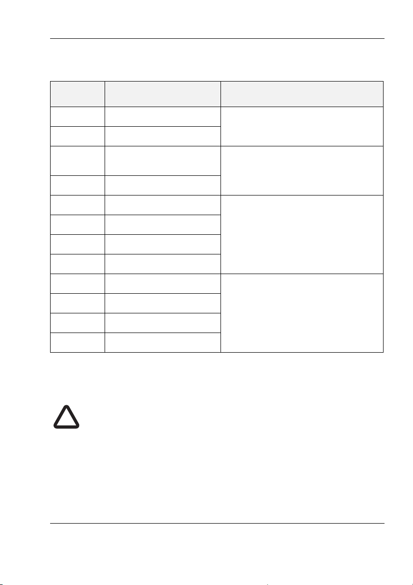
The table below lists the function of each colour coded wire for reference.
Wire
colour
Description Function
Red Power in + Power supply connections
Black Power in -
Light
Green
Switch connection External switch connections for
silent mode
Orange Switch connection
Brown NMEA 0183 port 1 TX+ High speed NMEA 0183 output
(38,400baud) intended for connection to chart plottersBlue NMEA 0183 port 1TX-
White NMEA 0183 port 1 RX+
Green NMEA 0183 port 1 RX-
Purple NMEA 0183 port 2 TX+ Low speed NMEA port
(4,800baud) intended for connec-
Pink NMEA 0183 port 2TX-
tion to other NMEA 0183 compatible sensors for multiplexing of data
Grey NMEA 0183 port 2 RX+
to the chart plotter
Yellow NMEA 0183 port 2 RX-
Table 2 Colour coding of wires in the accessory cable
The AIS transceiver is designed to operate at voltages from 9.6-31.2V,
however for optimum performance we would recommend maintaining the
voltage range at 12-24V.
Page 19
Page 22
Installation
Transmit +
Transmit –
Power in +
Power in –
Switch connection
Switch connection
Receive +
Receive –
Brown
Blue
Light green
Orange
Red
Black
White
Green
Purple
Pink
Grey
Yellow
Transmit +
Transmit –
Receive +
Receive –
NMEA 0183
Port 1
NMEA 0183
Port 2
It is recommended that crimped and soldered lugs are used to connect the
AIS transceiver to the power source using a suitable circuit breaker and/or 3A
fuse block. The red and black wires as shown in Figure 7 need to be
connected as follows:
1. Connect the red wire to a 12V or 24V power supply positive terminal.
2. Connect the black wire to the supply negative terminal.
Figure 8 Connecting the power supply
Page 20
Page 23

Installation
3.4 Location and fixing of the transceiver
Please note the following guidelines when selecting an installation location:
● The ambient temperature around the transceiver should be
maintained between -25°C and +55°C.
● The transceiver should not be located in a flammable or hazardous
atmosphere, such as in an engine room or near to fuel tanks.
● The transceiver must be fitted in a location where it is at least 0.2m
from a compass or any magnetic device.
● The transceiver should be mounted in a location where the LED
indicators are readily visible as they provide important information on
the status of the transceiver.
● WiFi & Bluetooth enabled variants (B922/B924/B952/B954) will
benefit from being installed near the center of the boat to provide a
consistent signal across all areas. The construction of your vessel
can also have an impact on performance. For example, metal
structural bulk heads and roofing, power cables and reflective
surfaces can reduce and in certain situations, block the signal.
Consider testing the reception to ensure you're happy before you
mount the bracket and transceiver.
● For optimum performance the transceiver should be mounted at least
1 metre away from other high power transmitting equipment like VHF
radios.
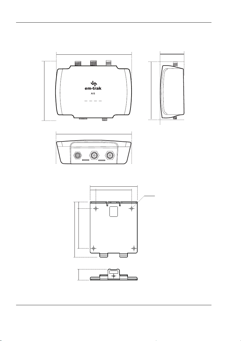
● There should be adequate space around the transceiver for routing
of cables. See Figure 9 for details of the transceiver dimensions.
Page 21
Page 24
Installation
150 mm
150 mm
43 mm
115 mm
115 mm
83.4 mm
60.3 mm 10 mm
71 mm
150 mm8.5 mm
3.4 mm DIA
60.3 mm
Figure 9 AIS transceiver dimensions
Figure 10 FLEXI-FIT bracket
Page 22
Page 25
Installation
FLEXI-FIT
™
bracket system
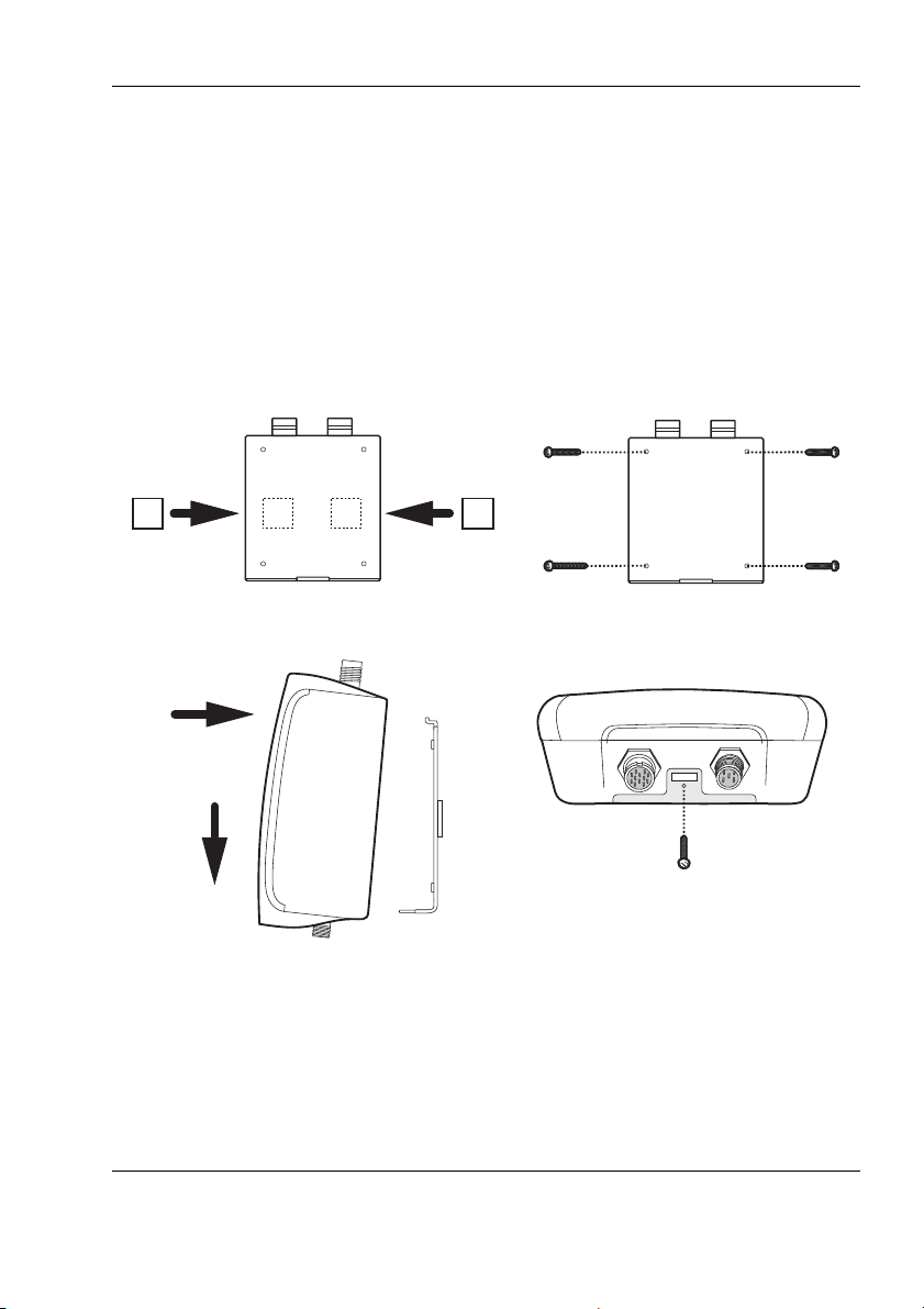
The B900 Series uses a simple bracket system to make installation as easy
as possible. Use the supplied bracket template to locate the desired position
of the transceiver and simply screw or stick (adhesive pads are also supplied)
the bracket to your vessel and then click the transceiver into the bracket. The
secure clip will hold the transceiver securely in even the most severe weather
and wave-shocks. For added security, there is a simple locking screw which
you can use to lock the transceiver to the bracket.
Figure 11 AIS transceiver mounting
Page 23
Page 26
Installation
USB
3.5 Configuration
Your transceiver will only be able to transmit once it has been configured with
appropriate vessel data.
3.5.1 Switching on your AIS transceiver for the first time
When power is applied to the transceiver for the first time all the status LED
indicators will flash briefly, leaving only the amber and red LED indicators
illuminated. You will now need to configure your transceiver, after which only
the green LED will be illuminated.
3.5.2 Configuring your AIS transceiver
Depending on the variant of transceiver there are three ways in which your
AIS transceiver can be configured:
Method 1: Configuration in advance by your dealer or installer.
If your AIS transceiver has been configured for you by your dealer or installer
you can proceed to Section . This is required for customers who have a USregistered vessel.
Method 2: Configuration using your PC
Figure 12 Configuration using your PC
Page 24
Page 27

Installation
Introduction to proAIS2
proAIS2 is available for download from www.em-trak.com/installation and
allows you to configure your transceiver using a PC or laptop over USB.
This configuration tool can be used to configure your vessel data, check the
GPS antenna performance, view details on surrounding vessels, and monitor
and diagnose the performance of the transceiver.
Installing proAIS2
1. Download and extract the zip file to your local PC or laptop. For Windows
installations you will need to open the 'en-us' folder and run the setup.exe
or proAIS2.msi files before following the on-screen prompts.
For MacOS X installations you will need to open the OSX folder and run
the proAIS2.dmg file.
2. If a security warning appears, click 'Install' to continue with the installation.
3. For Windows installations, the USB drivers can be optionally installed at
the same time. This is recommended for most installations and will be
required to allow your PC or laptop to recognise the transceiver COM port.
Once installation is complete, a start menu folder and shortcut can be created for future use.
Vessel data configuration using proAIS2
For configuration purposes only, it is possible to power the AIS transceiver
using USB only. This is useful if you wish to configure your AIS transceiver
away from the vessel power supply. The AIS transceiver will not transmit or
receive any data whilst powered by USB only.
You will require the following information in order to configure your AIS
transceiver:
● MMSI
● Vessel name
● Vessel type
● Vessel dimensions and position of your GPS antenna installation.
Page 25
Page 28

Installation
Please ensure that you enter all vessel data accurately. Failure to do
so could result in other vessels failing to identify your vessel
correctly. The vessel MMSI can only be configured once using
proAIS2. If you need to change the MMSI for any reason, please
contact your dealer or [email protected] and provide the
product serial number, current MMSI number and new MMSI
number.
!
WiFi configuration using ProAIS2
This section applies to WiFi & Bluetooth enabled variants only. (B922, B924,
B952 and B954)
Using the proAIS2 software, the WiFi interface can be configured for a user's
specific needs.
Connect the transceiver to the computer with a USB cable and apply external
power (12-24V). Run the proAIS2 software and press the “Connect” button.
Selecting the WiFi tab will enable you to configure the various WiFi
parameters.
The WiFi interface supports both Client and Access Point modes.
Client mode will allow your transceiver to join an existing network.
Access Point mode enables your transceiver to create it's own network.
The following parameters can be configured:
● WiFi network name (any name can be entered by user),
● IP address of the network (e.g. 192.168.0.1)
● Password - Any 8 characters or more.
● WiFi Channel - Preferably 1, 6, or 11).
● Port address (e.g. 2002)
Page 26
Page 29
Installation
Laptop
Tablet
Smartphone
Once the ‘Write Configuration’ button is pressed on proAIS2, the WiFi feature
will be enabled with these settings.
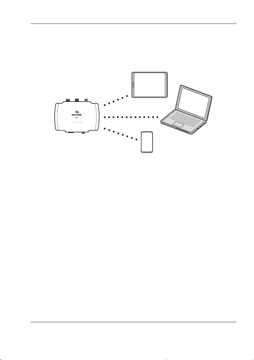
Figure 13 Typical mobile devices for WiFi & Bluetooth connection
Page 27
Page 30
Installation
Smartphone
Method 3: Configuration using your smartphone
Figure 14 Configuration using your smartphone
WiFi & Bluetooth enabled variants of the transceiver (B922/B924/B952/B954)
can be configured using the CONNECT-AIS app.
CONNECT-AIS is available for download from the App Store and Google
Play.
Once CONNECT-AIS is installed on your smartphone you will need to carry
out the following to configure your transceiver:
1. Ensure the transceiver is installed correctly and is powered up by 12 24V.
2. Start CONNECT-AIS. You will see a welcome screen.
3. Select “Lets Begin” and the “Setting up your AIS” screen will appear
4. If you have all your correct vessel information available select “I’m ready”
You will then see the “Connect to your devices” screen which will show all
the available WiFi devices within range.
Page 28
Page 31

Installation
5. Select the number of the transceiver being configured (this is printed on a
label on the side of the unit). Create a connection. You will see a message
confirming you are connected.
6. CONNECT-AIS will now guide you through configuring your vessel information. Complete the information boxes with the relevant vessel information and select “Next” when done.
7. Insert the vessel dimensions and select “Next” when done
8. Select the position of your GPS antenna aboard the vessel. (If you are
using the Integrated GPS receiver and antenna within the transceiver then
select the position of the transceiver instead). Select “Complete” when
done.
9. CONNECT-AIS will now display the active chart display which will show
other vessels with AIS in the vicinity.
The next time you open CONNECT-AIS it will connect automatically and go
straight to the home screen.
Page 29
Page 32

Installation
NMEA 2000
3.6 Connectivity
3.6.1 Connecting to an NMEA 2000 network
The transceiver can be connected to an existing NMEA 2000 network to
provide AIS and position data to other connected devices such as
chartplotters, instruments, sensors, etc.
Connection is made by a Micro-C drop cable to the existing NMEA 2000
network T-piece. This item is not supplied so you will need to purchase one
from your local dealer.
Figure 15 NMEA 2000 network connection
Starter kits are available to purchase if you do not already have an NMEA
2000 network.
The list of supported NMEA 2000 data (PGN’s) is detailed in Section 4.4
3.6.2 Connecting to your chartplotter
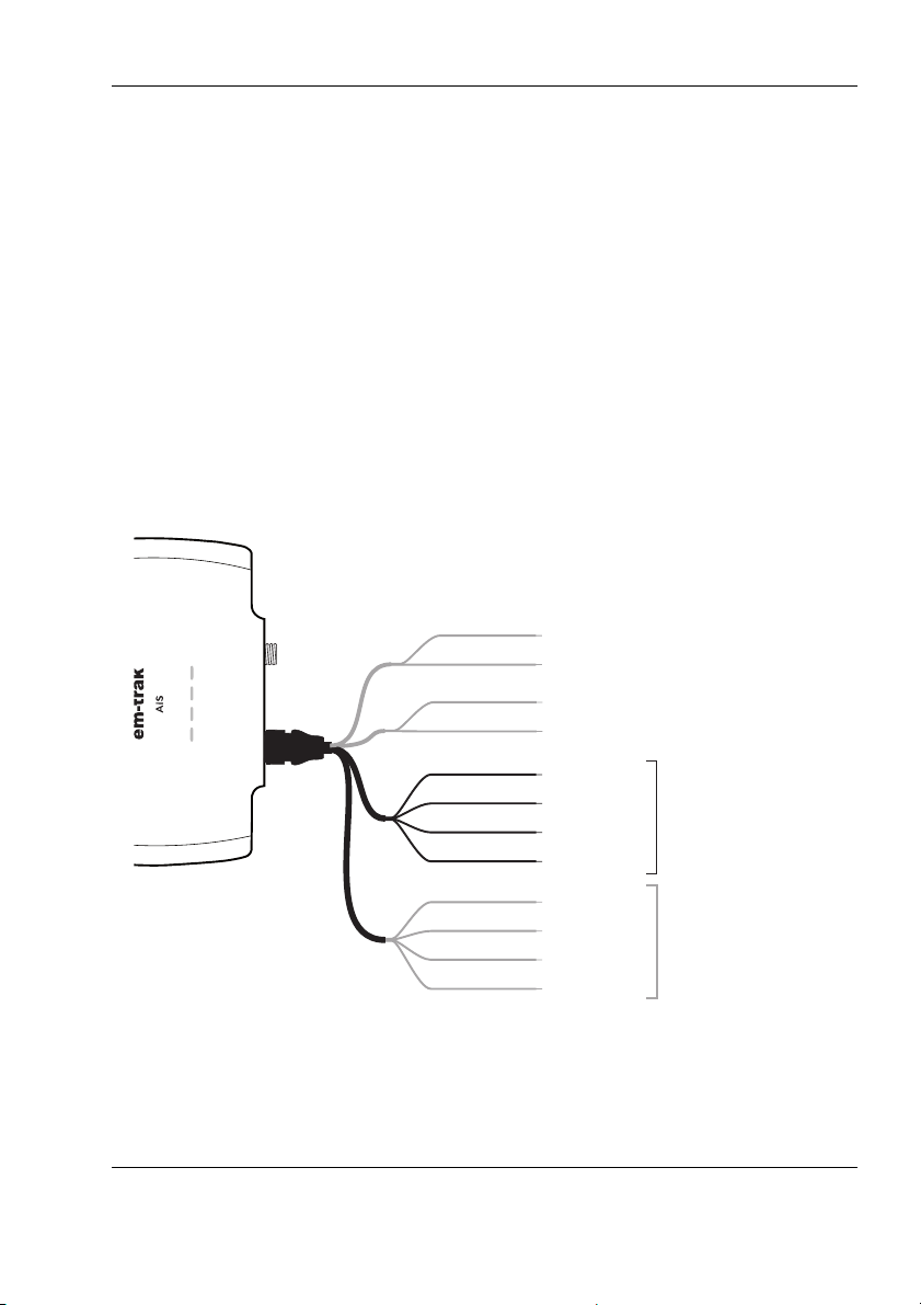
NMEA 0183 port 1 is recommended for connecting to a chartplotter,
operating at 38,400 baud by default. This can be changed using our
configuration tools if required. Four wires are provided for a bi-directional
connection, and are colour coded as shown in Figure 16.
Other manufacturers may use different signal names, however the following
general guidelines will apply:
● positive signals should be connected together
Page 30
Page 33
Installation
Transmit +
Transmit –
Power in +
Power in –
Switch connection
Switch connection
Receive +
Receive –
Brown
Blue
Light green
Orange
Red
Black
White
Green
Purple
Pink
Grey
Yellow
Transmit +
Transmit –
Receive +
Receive –
NMEA 0183
Port 1
38,400baud
(chart plotter)
NMEA 0183
Port 2
4,800baud
(other NMEA0183 device)
● negative signals should be connected together
● transmit signals should be connected to receive signals and vice
versa.
Please refer to your equipment manual for more information.
Both NMEA 0183 ports support multiplexing, which means that any data
received on port 1 will be automatically output on port 2, and vice versa.
This can be useful when connecting to a chartplotter that only has a single
NMEA 0183 port, so a sensor can be connected to port 2 on the transceiver,
where the received sensor data will combine with AIS data and get output on
port 1.
Figure 16 Connecting to your chartplotter
Page 31
Page 34
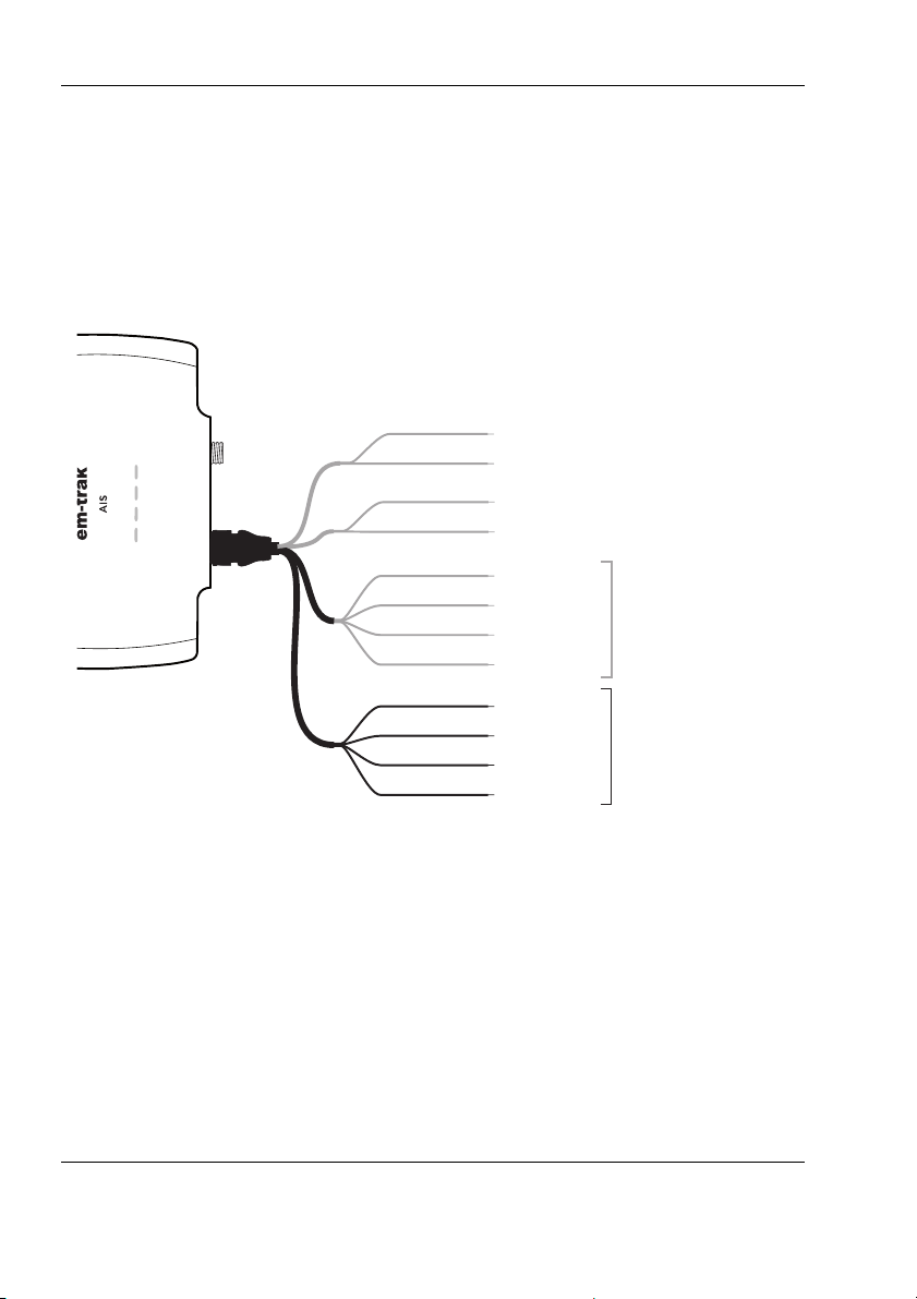
Installation
Transmit +
Transmit –
Power in +
Power in –
Switch connection
Switch connection
Receive +
Receive –
Brown
Blue
Light green
Orange
Red
Black
White
Green
Purple
Pink
Grey
Yellow
Transmit +
Transmit –
Receive +
Receive –
NMEA 0183
Port 1
38,400baud
(chart plotter)
NMEA 0183
Port 2
4,800baud
(other NMEA0183 device)
3.6.3 Connecting to your NMEA 0183 sensor
Connecting to your NMEA 0183 port 2 is recommended for connecting to
your sensor or NMEA 0183 compatible equipment operating at 4,800 baud by
default. This can be changed using our configuration tools if required. Four
wires are provided for a bi-directional connection, and are colour coded as
shown in Figure 17.
Figure 17 Connecting to your NMEA 0183 sensor
Page 32
Page 35
Installation
USB
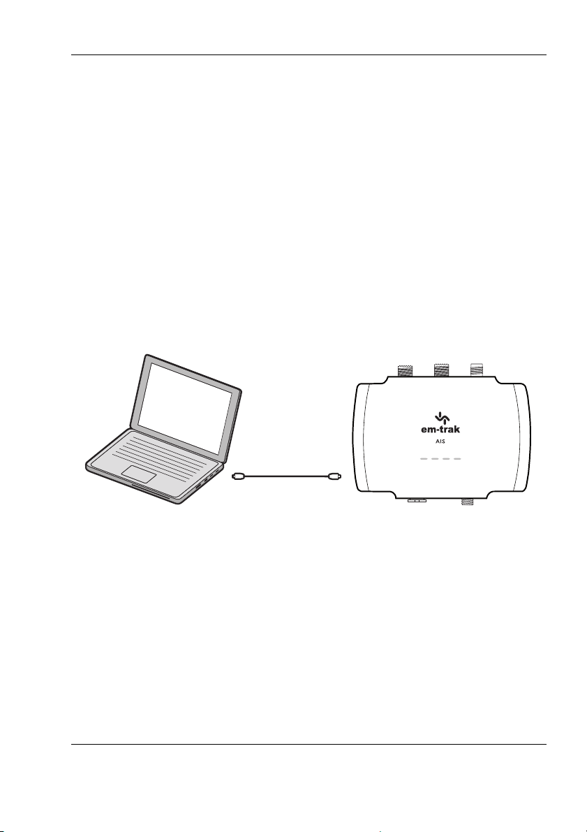
3.6.4 Connecting to your PC
A micro USB cable will be required to connect the transceiver to a PC or
laptop. This item is not supplied but is widely available for purchase.
USB drivers will need to be installed for Windows operating systems
(Windows 7 and up). These are installed automatically by using either
Windows Update or when installing proAIS2. proAIS2 is available for
download from www.em-trak.com/installation
USB drivers are typically not required for MacOS X operating systems.
Once your transceiver is communicating with your PC or laptop you can view
the received AIS data using a compatible navigation application.
Figure 18 Connecting to your PC
3.6.5 WiFi & Bluetooth connectivity
WiFi & Bluetooth enabled variants (B922/B924/B952/B954) can be
connected wirelessly to any mobile device. To establish a connection you will
need to select your transceiver from a list of detected devices. The device
name is known as the SSID - this is displayed in the WiFi tab of proAIS2 and
can be changed if required.
Page 33
Page 36

Installation
To stream AIS data to a navigation application you will then need to enter he
IP address and port number. This is also displayed in the WiFi tab of proAIS2
and can be changed if required.
Page 34
Page 37
Operation
LED Indicators
4 Operation
4.1 LED indicators
4.1.1 Using the AIS transceiver
Once the unit has been configured it is ready for use. Providing other vessels
installed with transceivers are within radio range of your vessel you should
see their details appear on the display devices that you have connected to
your transceiver. Please note that your full vessel details may not be visible to
other vessels immediately as static data messages (containing vessel name,
call sign, etc) are required to be transmitted every 6 minutes.
4.1.2 LED indicator functions
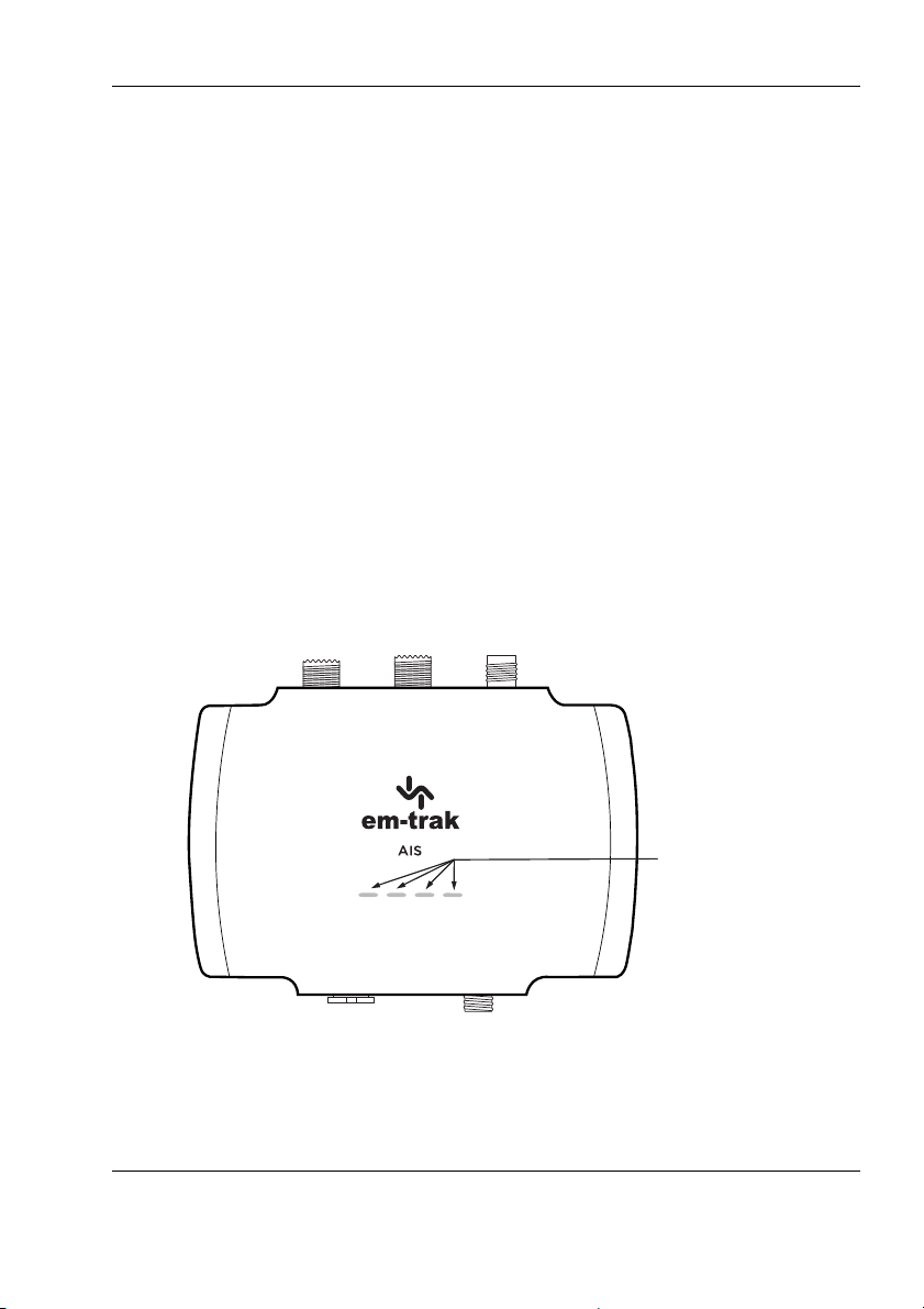
The AIS transceiver includes four coloured LED indicators as shown in Figure
19. The state of the LED indicators provide information regarding the status
of the AIS transceiver.
Figure 19 LED indicator location on the AIS transceiver unit
Page 35
Page 38
Operation
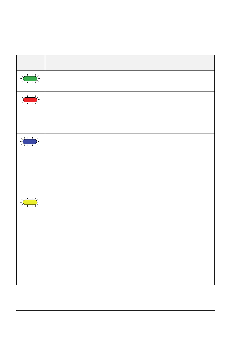
The meaning of each LED indicator is shown in the table below. Figure 19
shows the LED indicator positions on the AIS transceiver.
LED
indicator
Function
Green LED indicator
Indicates that the AIS transceiver is configured and powered up.
Red LED indicator
Indicates that the AIS transceiver has detected a system error.
The likely causes of this are detailed in the troubleshooting guide
in Section . Alarms displayed in the Diagnostic tab of proAIS2 will
also assist with troubleshooting.
Blue LED indicator
Indicates that silent mode is enabled. Silent mode is a feature of
the B900 Series that ceases the transmissions from your own
vessel, whilst the reception of other vessel position reports
continue.
You can activate this using the configuration tools or by
activating the toggle switch as detailed in Section 4.2.
Amber LED indicator
Indicates that the AIS transceiver is not transmitting. This can be
for a number of reasons:
● The AIS radio channels are exceptionally busy so there
are currently no available slots for transmission.
● The unit has been in silent mode and after deactivating
silent mode this amber LED indicator will illuminate until
the first AIS message has been sent
● The AIS transceiver has been commanded by the local
authority (via an AIS base station) to cease
transmissions.
Table 3 LED indicator functions
Page 36
Page 39
Operation
When silent mode is active other vessels will not be able to
receive your vessel information on their AIS devices. Your
navigational safety may be compromised as a result.
!
Do not connect a voltage source across the switch inputs as
this may damage the transceiver.
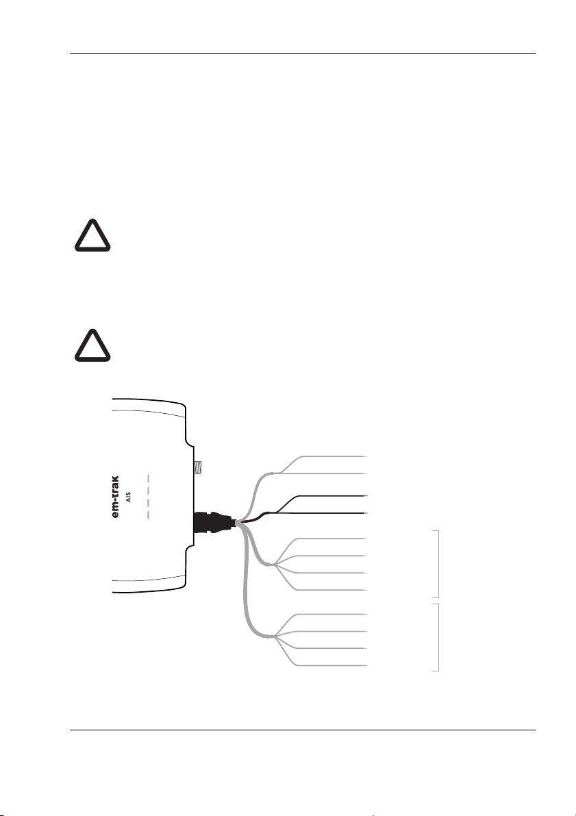
!
Transmit +
Transmit –
Power in +
Power in –
Switch connection
Switch connection
Receive +
Receive –
Brown
Blue
Light green
Orange
Red
Black
White
Green
Purple
Pink
Grey
Yellow
Transmit +
Transmit –
Receive +
Receive –
NMEA 0183
Port 1
NMEA 0183
Port 2
4.2 Silent mode
An external switch enables / disables ‘silent mode'. In silent mode the
transmission of your own vessel position ceases, whilst the reception of other
vessel's AIS position continues. When silent mode is active the blue LED
indicator will be illuminated.This is also reflected in the Diagnostics tab of
proAIS2.
Connect the toggle switch between the light green and orange wires as
shown in Figure 20. This is optional and not essential for normal operation of
the product.
Figure 20 Connecting an external switch
Page 37
Page 40

Operation
4.3 Voyage data recorder
This feature is available on transceivers with the WiFi & Bluetooth only (B922,
B924, B952 and B954).
The transceiver will log your own position at regular intervals if your position
has changed by more than 10m. Data is stored for 30 days.
The VDR log can be retrieved from the VDR tab within proAIS2.
The start and end dates of the log file are interrogated so you can select a
date range to download.
Once the date range is selected you need to select the download location.
Data is saved as RMC sentences, which can be decoded and displayed by a
range of on-line tools and navigation applications.
Page 38
Page 41

Operation
4.4 PGN table
PGN’s are useful for understanding the detailed information that your
transceiver receives and transmits on an NMEA 2000 network. The PGN’s
listed in Table 4 are supported by the transceiver. There are no unused fields.
PGN
(Dec.)
PGN
(Hex.)
Title in NMEA database Usage
059392 0E800 ISO Acknowledgment in, out
059904 0EA00 ISO Request in, out
060416 0EC00 ISO Transport Protocol -
in, out
Data
060160 0EB00 ISO Transport Protocol -
in, out
Connection
060928 0EE00 ISO Address Claim in, out
065240 0FED8 ISO Commanded
in
Address
126208 1ED00 Group Function in, out
126464 1EE00 PGN list - Group Function in, out
126992 1F010 System time out
126993 1F011 Heartbeat out
126996 1F014 Product Information in, out
126998 1F016 Configuration Information out
NMEA 0183
127250 1F112 Vessel Heading in HDT/THS
127251 1F113 Rate if Turn in ROT
Page 39
Page 42

Operation
129025 1F801 Position, Rapid Update out RMC
129026 1F802 COG & SOG. Rapid
out RMC
Update
129029 1F805 GNSS Position data out RMC
129038 1F80E AIS Class A Position
out VDM/VDO
Report
129039 1F80F AIS Class B Position
out VDM/VDO
Report
129040 1F810 AIS Class B Extended
out VDM/VDO
Position Report
129041 1F811 AIS AtoN Report out VDM/VDO
129793 1FB01 AIS UTC and Date Report out VDM/VDO
129794 1FB02 AIS Class A Static and
out VDM/VDO
Voyage Related Data
129795 1FB03 AIS Addressed Binary
out VDM/VDO
Message
129796 1FB04 AIS Acknowledge out VDM/VDO
129797 1FB05 AIS Binary Broadcast
out VDM/VDO
Message
129798 1FB06 AIS SAR Aircraft Position
out VDM/VDO
Report
129801 1FB09 AIS Addressed SRM out VDM/VDO
129802 1FB0A AIS Safety Broadcast
out VDM/VDO
Binary Message
129809 1FB11 AIS Class B CS Static
out VDM/VDO
Data Report Part A
Page 40
Page 43

Operation
129810 1FB12 AIS Class B CS Static
Data Report Part B
Table 4 NMEA 2000 PGN List
out VDM/VDO
Page 41
Page 44

Troubleshooting
5 Troubleshooting
Issue Possible cause and remedy
No LED indicators
are illuminated
The red error LED
indicator is flashing
The red 'error' LED
indicator is
illuminated
● Check that the power supply is connected
correctly.
● Check that the power supply is a 12V or 24V
supply.
There may be a problem with the VHF antenna system. This can be confirmed using proAIS2. If the
'High VSWR' alarm is active please check for the following:
● Faulty VHF antenna/cable/connectors
● Poor connection at the VHF antenna/cable/
connectors
● Suitability of the VHF antenna (for AIS only we
recommend antennas covering 162MHz / for
splitter variants we recommend antennas
covering to 159MHz)
● VHF antenna location (ensure that is isn't
mounted near other transmitting antennas or
sources of interference, metal structures, or
other obstructions)
● Check that the unit is configured with a valid
MMSI number. This can be confirmed using the
Configuration tab in proAIS2
● Check that the GPS antenna has a stable
position fix. This can be confirmed using the GPS
Status tab in proAIS2
● Check that the power supply is within 12 - 24V.
This can be confirmed using the Diagnostics tab
of proAIS2
Page 42
Page 45

Troubleshooting
The amber LED
indicator is flashing
continuously
No data is being
received by the
chart plotter
My vessel name
isn't being received
by other vessels
I can't establish a
connection using
WiFi or Bluetooth
● The amber LED indicator flashes while the
transceiver searches for a position fix. If it takes
longer than a minute you can check the
performance of the GPS antenna by using the
GPS Status tab of proAIS2
● Check that the signal wires are connected
correctly.
● Check that the baud rate matches both the
transceiver and the chart plotter.
● Confirm that other vessels are within radio range
and that they are displayed on the Other Vessels
tab of proAIS2.
● Static data (containing vessel name, call sign,
etc) is transmitted every 6 minutes so it may take
a few transmissions before all the vessel data is
displayed.
● Position reports contain critical data like position,
MMSI number, vessel speed, etc and these are
transmitted more regularly.
● Check that the transceiver is powered by 12 24V
● Check the configuration parameters using
proAIS2
● Check that there are no obstructions between
the transceiver and mobile device
● Check that there are no sources of interference
nearby
Table 5 Troubleshooting
If the guidance given above does not rectify the problem you are
experiencing, please contact your dealer or [email protected] for further
assistance.
Page 43
Page 46

Specifications
6 Specifications
Parameter Value
Dimensions 149 x 118 x 47 mm (L x W x H)
Weight Transceiver only variants 320g
Transceiver with splitter variants 345g
Input voltage DC 12 - 24V (9.6 - 31.2V maximum)
Average power
consumption
Peak current
rating
GPS Receiver
(AIS integrated)
Electrical
Interfaces
Connectors VHF antenna connector (SO-239)
Transceiver variants (B921/B922/B951/B952): 170mA /
1.6W at 12VDC
Splitter variants (B923/B924/B953/B954):
280mA / 2.1W at 12VDC
B921/B922/B951/B952 2A
B923/B924/B953/B954 2.5A
50 channel IEC 61108-1 compliant
NMEA 0183 38,400 baud
NMEA 2000 LEN=1
WiFi 2.4GHz IEEE 802.11 a/b/g/n
Output power +15dBm
Bluetooth V4.0 / Output power +11dBm
VHF radio connector (SO-239) - only applicable to
splitter variants B923/B924/B953/B954
External GPS antenna connector (TNC)
NMEA 2000 connector (Micro-C)
Power/NMEA 0183/silent mode connector (12 way)
USB micro connector
Page 44
Page 47

Specifications
VHF Transceiver Transmitter x 1
Receiver x 2 (Receivers time shared between AIS and
DSC)
Frequency: 156.025 to 162.025 MHz in 25 kHz steps
Output Power
33dBm ± 1.5 dB
CSTDMA
Output Power
37dBm ± 1.5 dB
SOTDMA
Channel
25kHz
Bandwidth
Channel Step 25kHz
Modulation
Modes
25kHz GMSK (AIS, TX and RX)
25kHz AFSK (DSC, RX only)
Bit rate 9600 b/s ± 50 ppm (GMSK)
1200 b/s ± 30 ppm (FSK)
Receiver
Performance
Sensitivity better than -107dBm at 20% PER
Co-channel 10dB
Adjacent channel 70dB
IMD 65dB
Blocking 86dB
Environmental Weather and waterproof to IPx7 & IPx6
Operating temperature: -25ºC to +55ºC
Tested to IEC 60945 'Exposed' category
LED indicators Power, TX status, error, silent mode status
Table 6 Specifications
Page 45
Page 48

About AIS
7 About AIS
7.1 About AIS
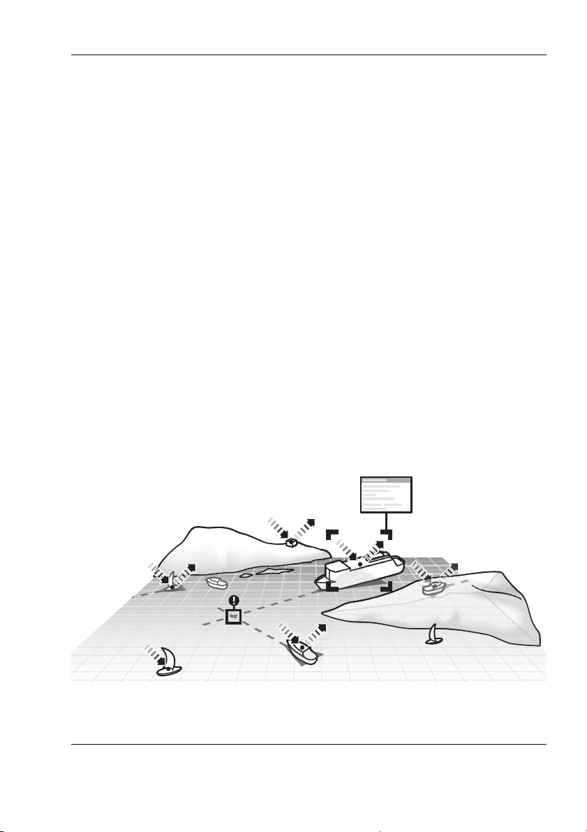
The marine Automatic Identification System (AIS) is a location and vessel
information reporting system. It allows vessels equipped with AIS to
automatically and dynamically share and regularly update their position,
speed, course and other information such as vessel identity with similarly
equipped vessels. Position is derived from the Global Navigation Satellite
System (GNSS) and communication between vessels is by Very High
Frequency (VHF) digital transmissions.
There are a number of types of AIS device as follows:
● Class A transceivers. These are similar to class B transceivers, but
are designed to be fitted to large vessels such as cargo ships and
large passenger vessels. Class A transceivers transmit at a higher
VHF signal power than class B transceivers and therefore can be
received by more distant vessels. They also transmit Class A
transceivers are mandatory on all vessels over 300 gross tonnes on
international voyages and certain types of passenger vessels under
SOLAS regulations.
● Class B transceivers. Similar to class A transceivers in many ways,
but are normally lower cost due to the less stringent performance
requirements. Class B transceivers transmit at a lower power and at
a lower reporting rate than class A transceivers.
● AIS base stations. AIS base stations are used by Vessel Traffic
Systems to monitor and control the transmissions of transceivers.
● Aids to Navigation (AtoN) transceivers. AtoN’s are transceivers
mounted on buoys or other hazards to shipping which transmit
details of their location to the surrounding vessels.
● AIS receivers. AIS receivers will generally receive transmissions
from class A transceivers, class B transceivers, AtoN’s and AIS base
stations but do not transmit any information about the vessel on
which they are installed.
Page 46
Page 49
About AIS
7.2 Static and dynamic vessel data
There are two categories of information transmitted by a transceiver: static
and dynamic data.
The vessel's dynamic data, which includes location, speed over ground
(SOG) and course over ground (COG), is calculated automatically using the
integrated GPS receiver.
Static data is information about the vessel which must be configured into the
AIS transceiver. This includes:
● Maritime Mobile Service Identity (MMSI)
● Vessel name
● Vessel call sign (if available)
● Vessel type
● Vessel dimensions
In most countries the operation of a transceiver is included under the vessel's
marine VHF license provisions. The vessel on to which the AIS unit is to be
installed must therefore possess a current VHF radiotelephone license which
lists the AIS system, vessel Call Sign and MMSI number.
Figure 21 The AIS network
Page 47
Page 50

List of abbreviations
8 List of abbreviations
AIS Automatic Identification System
AIS SART AIS Search and Rescue Transmitter
AP Access Point (Relating to WiFi behaviour)
AtoN AIS Aid to Navigation
CD Compact Disc
CE European Declaration of Conformity
COG Course Over Ground
COM Common (electrical)
CPA Closest Point of Approach
CS Carrier Sense
DC Direct Current
Dec Decimal
DGPS Differential GPS
DGPS Differential GNSS
DHCP Dynamic Host Configuration Protocol
DOP Dilution of Precision
DSC Digital Selective Calling
DTM Datum
ECDIS Electronic Chart Display and Information System
ENI Unique European Vessel Identification Number
EPFS Electronic Position Fixing System
EPIRB Emergency Position Indicating Radio Beacon
ERI Electronic Reporting International
Page 48
Page 51

List of abbreviations
ETA Estimated Time of Arrival
EXT External
FCC Federal Communications Committee
GBS GPS satellite fault detection message
GFA GPS fix accuracy and integrity message
GGA Global positioning system (GPS) fix data message
GLL Geographic position - Latitude/longitude message
GLONASS Globalnaya Navigazionnaya Sputnikovaya Sistema
(Russian GPS)
GND Electrical Ground
GNS GPS fix data message
GNSS Global Navigation Satellite System
GPS Global Positioning System
GRS GPS range residuals message
GSA GPS DOP and active satellites message
GSV GPS satellites in view message
HDT Heading true message
Hex Hexadecimal
IEC International Electrotechnical Commission
IMO International Maritime Organisation
INT Internal
IPx6 Ingress Protection (to powerful water jets)
IPx7 Ingress Protection (1m immersion for 30 minutes)
ISO International Standards Organisation
Kt Knots
Page 49
Page 52

List of abbreviations
LAT Latitude
LCD Liquid Crystal Display
LON Longitude
LR Long Range
MKD Minimum Keyboard and Display
MMSI Maritime Mobile Service Identity
MOB Man Overboard
NC Normally Closed (electrical)
NAV Navigation
NM Nautical Miles
NMEA National Marine Electronics Association
PDF Portable Document Format
PGN Parameter Group Number
PI Presentation Interface
RAIM Receiver Autonomous Integrity Monitoring
RED Radio Equipment Directive
RF Radio Frequency
RMC Recommended minimum specific GPS data message
ROT Rate of Turn
RX Receive
SD Secure Digital
SO Self Organised
SOG Speed Over Ground
SOLAS Safety of Life at Sea
SRM Safety Related Message
Page 50
Page 53

List of abbreviations
TCP Transmission Control Protocol
TCPA Time to Closest Point of Approach
TDMA Time Division Multiple Access
THS True heading and status message
TNC Threaded Neill–Concelman (a type of connector)
TPI Threads per Inch
TX Transmit
UDP User Datagram Protocol
UHF Ultra High Frequency
UTC Co-ordinated Universal Time
VBW Dual ground/water speed message
VDM All VDL AIS messages received
VDO AIS own-ship broadcast data
VHF Very High Frequency
VSWR Voltage Standing Wave Ratio
VTG Course over ground and ground speed message
WGS84 World Geodetic System 1984
WEEE Waste Electrical & Electronic Equipment
WiFi Wireless networking technology
Page 51
Page 54

List of abbreviations
Page 52
Page 55

Page 56

Head office:
em-trak Marine Electronics Ltd
Wireless House
Westfield Indistrial Estate
Midsomer Norton
Bath, BA3 4BS
United Kingdom
T +44 (0)1761 409559 | F +44 (0)1761 410093
[email protected]
Regional Office:
em-trak Marine Electronics Limited
470 Atlantic Avenue
4th floor,
Boston MA 02210
USA
For support enquiries email: [email protected]
201-0952:2
www.em-trak.com
The em-trak B900 Series transceivers are an aid to navigation and must not be relied upon
to provide accurate navigation information. AIS is not a replacement for vigilant human
lookouts and other navigation aids such as RADAR. The performanceof the B900 series may
be seriously impaired if not installed as instructed in the user manual, or due to other
factors such as weather and or nearby transmitting devices. Compatibility with other
systems may vary and is reliant on the third party systems recognising the standard
outputs from the B900 series transciever. em-trak reserves the right to update and change
these specications at any time without notice.
High Performance Maritime Products
 Loading...