


a Free Download from AnalogRules.com
Contents |
Page |
|
|
|
|
Hints for unpacking and transporting |
1 |
|
Small parts |
|
|
A |
Preparing the unit for operation |
|
|
A 1 Opening of the unit and |
|
|
removal of the transit protections |
3 |
|
A 2 Preparatory work on the unit |
3 |
|
A 3 Mains connections |
5 |
|
A 4 Earthing |
6 |
|
A 5 Connecting the signal lines |
7 |
|
A 6 Fitting and connecting of the |
|
|
accessories for remote |
7 |
|
A 7 Calibration of Reverberation |
|
|
Time Indication. |
8 |
|
A 8 Test tape |
8 |
B |
Electrical tests and adjustments after initial installation |
|
|
B 1 Setting up the amplifier gain |
|
|
without reverberation plate |
9 |
|
B 2 Adjusting the overall gain via |
|
|
the reverberation plate |
9 |
|
B 3 Frequency response measurements |
10 |
C Connecting the reverberation unit into the signal path |
|
|
|
C 1 Basic principles |
11 |
|
C 2 Stereo / Mono operation |
11 |
D |
Practical operating hints |
|
|
D 1 Units without remote control |
12 |
|
D 2 Units with remote control |
12 |
|
D 3 Bass cut at the amplifier |
13 |
Technical data EMT 140 FB-TS |
14 |
|
Technical data EMT 162 TS |
15 |
|
a Free Download from AnalogRules.com
Outline size |
17 |
Circuit diagram. EMT 140 FB-TS |
|
EMT 162 TS front view |
19 |
EMT 162 TS rear view |
20 |
EMT 162 TS with open lid |
21 |
Circuit diagram EMT 162 TS |
22 |
Adjustments and test points EMT 162 TS |
23 |
Print board EMT 162 TS |
24 |
Frequency responses EMT 162 TS |
25 |
Tolerance field EMT 140 TS |
26 |
Connection diagram for reverberation generation |
27 |
Circuit diagram for multiple control |
|
desk arrangements |
28 |
Spare parts |
29 |
Service Instructions |
30 |
EMT 140 Q |
33 |
a Free Download from AnalogRules.com
Small parts
EMT 140 TS
Reverberation Unit:
1 Hand wheel, complete
1 Plastic disk
2 open-end wrenches
8 Wire Clips
2 Clip guards
2 Plugs T 3084-2
or: 2 Plugs Cannon XLR-12c 2 Plugs Cannon XLR-13c
1 Power cord (US-version)
1 Power plug*
1 Driver magnet, complete
EMT 140 F
Remote control Motor unit:
1 Fuse 1 A slow-blow 20 mm x 5 mm 0 1 Fuse 1 A slow-blow 1 1/4" x 1/4"
1 Plug T 3055
1 Coupling disk (plastic)
1 Screw cap (US-version)
EMT 140 B
Remote Control Operating Unit:
1 Bulb socket
1 Bulb 24 V/80 mV
1 cap with lens
1 Resistor 2000 ohms 0.25 W 5 %
1 Condenser 0.1/uF 400 V
1 Toggle switch
2 Fuses 0.5 A, 20 mm x 5 mm
1 Screw cap (Europe version)
1 Fuse holder
2 Fuses 0.5 A, 1 1/4 " x 1/4
1 Screw cap (US-version)
a Free Download from AnalogRules.com
Please read Carefully before unpacking
Hints for unpacking and transporting:
1.The equipment should only be moved short distances after being unpacked.
2.Make sure the case is standing the right way up. The arrows must point upwards.
3.The front of the case should be opened first.
Remove nails carefully. Do not use crowbars or levers.
4.The sketch on the front of the Reverberation Unit shows how if should be lifted from the base of the packing case and moved to it’s destination. During transport the dial indicating reverberation time must be at the fop. The equipment should only be moved in an upright position.
5.Only when standing at ifs final destination should the Reverberation Unit be made ready for operation.
6.Before opening the equipment if is essential that the operating instructions are studied carefully.
a Free Download from AnalogRules.com
A. Preparing the unit for operation
The reverberation unit EDIT 140 is a high precision electroacoustic device requiring particular protec tion during transit. Only when the unit has been unpacked and placed in its final location should the pro tecting devices be removed and the unit prepared for operation.
A1 OPENING OF THE UNIT AND REMOVAL OF THE SHIPPING PROTECTIONS |
|
1. First unscrew the two side-plates, then the top cover-plate |
|
(the two end-plates and the base-plate should be left on). |
|
2. Untie the two cartons with accessories from the base-plate and remove them. Remove the card |
board |
pieces between the reverberation plate and the traverse units. Untie the moving parts of the damp |
ing |
plate. |
|
When packed for airfreight, the foam rubber strips between steel-plate and damping plate have to be removed.
3. Untie the shielded cables (with Co-ax plug) from the traverse and plug into the amplifier input sockets. Plug colored Co-ax plug into "left-hand" channel.
A2 PREPARATORY WORK ON THE UNIT
The various sections should be prepared for operation as follows:
1. The reverberation plate (large steel sheet)
It is held in the tubular frame by means of two steel clips on each side - i.e. 8 altogether - (spare steel clips are provided) which are attached to threaded bolts. The reverberation plate can be tensioned in the frame by means of the nuts on these bolts.

a Free Download from AnalogRules.com
Before shipment four of
these nuts (see drawing) have been loosened at the factory by exactly a quarter of a turn (900) counter-clockwise. Therefore, the standard practice is to tighten the plate by means of the same screws exactly 90* clockwise.
However, this applies only if no stressing of the steel clips occurred during transport - which may be caused by shocks etc. In this case, more tension is necessary to obtain the original state.
In case of doubt we strictly recommend to have the plate more stressed instead of having it too loose. With too high tension most probably the frequency response will run out of the tolerance field (too low at bass end), but in the same way distortion with low frequencies will be reduced.
In order to vary the tension of the plate, proceed as follows:
The inner nuts must be held in position (they must not be allowed to turn) while loosening the outer lock nuts. The inner nut should now be turned. It should be then held in this position while tightening up the lock nut.
The only criterion for correct tensioning are the electroacoustic properties (check of overall response see B 3).
If a re-tensioning of the steel-plate is neccessary (e.g. because a spring has been broken during transport) please refer to B 3, "Frequency response measurements (T - 2 S)".
After tensioning, the top cover-plate of the wooden housing should be replaced.
2. The damping plate
Its distance from the reverberation plate can be varied by means of the parallel guide mechanism (adjustment of reverberation time). The damping plate is adjusted at the factory so as to achieve - with the damping plate turned in - the smallest defined reverberation time ((equal to or less than 1 s).
The hand wheel, which is supplied separately, is for adjusting the reverberation time. It is pushed through the plate with the scale marking on the top of the unit onto the shaft which operates the lever mechanism of the damping plate. Before fixing the hand wheel on this shaft one should ascertain that the pointer is within the scale.
a Free Download from AnalogRules.com
In units without internal remote control the damping plate should be easily movable by turning the hand wheel. With minimum reverberation time the damping plate must not touch the steel plate. This applies to units with remote control as well.
3. The driving system
The black enamelled mounting-plate around the moving coil is for mounting and adjusting the driver magnet system which is supplied separately. The mounting plate is fixed to the central traverse by means of four screws. It can be adjusted by loosening these screws. By means of the plastic plate which is provided, the concentricity of the magnet and the moving coil may be checked after tensioning the reverberation plate. If the systems are concentric the plastic adjusting plate can be pushed easily onto the moving coil and inserted into-the four guides for the mounting plate. The driver magnet system should-then be pushed carefully over the moving coil without brushing against it and screwed to the mounting plate. The DC resistance of the moving coil is 12.5 ohms.
4. The pick-up systems
All versions of the EMT Reverberation Unit are equipped with two pick-up systems. They are accessible on the two outer traverses and are protected by a shielding can. By opening the lid of these cans, it is possible to ascertain that:
The microphone system (capacity approximately 500 pF) is able to move freely inside the can and the leads to the soldering lugs are also free.
Replace the lid of the can.
Then screw on the two wooden side-covers again and fix the top cover. Now the preparation has been finished.
The EMT-Reverberation Unit is protected against ambient noise by rubber suspension blocks between case and frame. However, with excessive ambient noise, additional suspension of the total unit is advisable.
A3 POWER CONNECTIONS
A three-conductor cable may be attached to the AC connector which is provided.
The EMT Reverberation Unit will be set at the factory to the AC voltage quoted in the order. This voltage is entered in the delivery papers. If no definite voltage was decided upon when ordering, the unit will be supplied with the AC voltage set to 220 V/50 Hz.
The units EMT 140 FB and EMT 140 FBst (with internal remote control) which are supplied for AC voltage of 110 V, 117 V, or 240 V are equipped with an additional transformer "S 140- B" which will be set at the factory to the -required AC voltage.
Instructions for changing the primary voltage on the additional transformer are contained in the drawing "S 140-232.B" at the end of this operating manual.
IMPORTANT
a Free Download from AnalogRules.com
The amplifier has to be set separately to the actual AC power voltage. The respective current of the fuse should be observed. The setting is done by means of the slide switch (100 V - 130 V and 190 V - 260 V) at the rear of the amp1ifier.
If a reverberation unit EMT 140 or EMT 140 st which is operated from an AC voltage other than 220 V is to be equipped subsequently with the internal remote control outfit EMT-140 F, an additional transformer "S 140-232 W' must be used. (Please note this when ordering.)
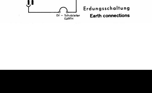
A4 OPERATING GROUND, AC GROUND, CHASSIS, ZERO-VOLT (MINUS)
In order to comply with the requirements of the numerous Safety Authorities, the following connections are available:
AC ground: |
Connection via power cord. |
External ground: |
Connection to screw on front panel. |
Zero-volt/AC ground: |
This connection is accessible on |
|
the print (covered by a plastic shield) inside the unit. |
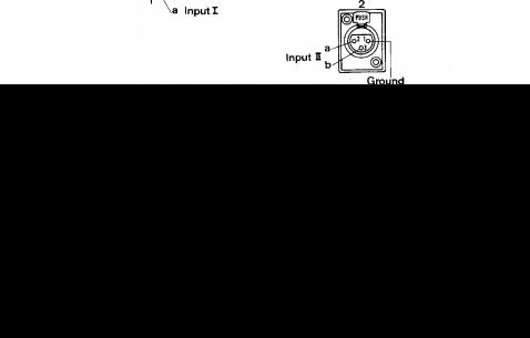
In the amplifier EMT 162 TS, the following connections are available:
AC ground / Chassis: |
At the rear of amplifier. |
Zero-volt / Chassis |
Soldered connection inside the amplifier |
|
|
|
|
|
|
|
|
A5 CONNECTING THE SIGNAL
a Free Download from AnalogRules.com
LINES
The connectors which are provided should be connected to the incoming and outgoing signal leads in accordance with the "test circuit EMT 140 FB-TS".
A6 INSTALLING AND CONNECTING THE ACCESSORIES FOR INTERNAL REMOTE CONTROL
On the units EMT 140 FB-TS the reverberation time can be varied by means of a remote control unit from the mixer. For this purpose the remote control unit EMT 140 B which is supplied, the toggle-switch with its accessories and the pilot lamp should be built into the mixer.
The reverberation time can be varied at any time on the unit itself - e.g. for testing - by means of the switch on the connecting plate ("+" increase, "-" decrease reverberation time).
The control unit EMT 140 B should be connected in accordance with the circuit diagram EMT 140 FB-TS via an 8-conductor cable and by means of the 8-pole TUCHEL connector T 3055/10 which is provided with the reverberation unit. By means of the toggleswitch, the entire reverberation unit can be remotely switched on and off from the mixer. The AC switch on the amplifier must in this case be permanently left in the "ON" position. The pilot lamp on the mixer will light up when the unit is switched on.
For testing purposes the unit may be switched on directly (by means of the switch on the mains plate of the unit) independently
of the AC switch on the mixer. However, the pilot lamp on the mixer will not light up in this case.
The remote control requires an operating voltage of 24 V DC. If a unit is ordered for other control supply voltages, this will be specially noted in the delivery papers.
 Loading...