

Page 1
INSTALLATION INSTRUCTIONS
AND
OWNER'S MANUAL
GRAVITY VENTED
DUAL WALL FURNACE
MODEL
GWT-50-3 (SG, RB)
Installer: Leave this manual with the appliance.
Consumer: Retain this manual for future reference.
WARNING: If not installed, operated and maintained
in accordance with the manufacturer's instructions,
this product could expose you to substances in fuel
or from fuel combustion which can cause death or
serious illness.
WARNING: If the information in these instructions
are not followed exactly, a re or explosion may
result causing property damage, personal injury or
loss of life.
— Donot storeor usegasoline orother ammable
vapors and liquids in the vicinity of this or any
other appliance.
— WHAT TO DO IF YOU SMELL GAS
• Do not try to light any appliance.
• Do not touch any electrical switch; do not use
any phone in your building.
• Immediately call your gas supplier from a
neighbor’s phone. Follow the gas supplier’s
instructions.
• If you cannot reach your gas supplier, call the
redepartment.
— Installation and service must be performed by a
qualiedinstaller,serviceagencyorthegassupplier.
Page 1
Page 2

TABLE OF CONTENTS
SECTION PAGE
Important Safety Information ....................................................................................3
Safety Information for Users of LP Gas ...................................................................4
Introduction ..............................................................................................................5
Specications ...........................................................................................................5
Recommended Vent Conguration ..........................................................................6
Gas Supply ...............................................................................................................7
Clearances ..............................................................................................................8
Ventilation and Combustion Air ................................................................................8
Location - All Models ................................................................................................8
Rough-In Instructions ............................................................................................8-9
Finishing Instructions ..........................................................................................9-10
Optional Thermostat Location (SG Models) ........................................................... 11
Lighting Instructions ...............................................................................................12
Vent Safety Shutoff System ...................................................................................13
Proper Main Burner Flame .....................................................................................13
Proper Pilot Flame .................................................................................................13
Troubleshooting ......................................................................................................14
Parts List ................................................................................................................15
How To Order Repair Parts ....................................................................................15
Parts View .............................................................................................................16
Remote Bulb Control Installation Instructions ........................................................17
Optional Blower Installation Instructions .......................................................... 18-19
Service Notes .........................................................................................................20
Master Parts Distributor List ...................................................................................21
Warranty .................................................................................................................22
32039-1-0314Page 2
Page 3

IMPORTANT SAFETY INFORMATION
THIS IS A HEATING APPLIANCE
DO NOT OPERATE THIS APPLIANCE WITHOUT OUTER CASING INSTALLED.
• Due to high temperatures the appliance should be
locatedoutoftrafcandawayfromfurnitureand
draperies.
• Children and adults should be alerted to the hazards
of high surface temperatures and should stay away
to avoid burns or clothing ignition.
• Young children should be carefully supervised when
they are in the same room as the appliance.
• Clothingorotherammablematerialshouldnotbe
placed on or near the appliance.
• Any safety screen or guard removed for servicing
an appliance must be replaced prior to operating
the appliance.
• Keep burner and control compartment clean.
• Installation and repair should be done by a
QUALIFIED SERVICE PERSON. The appliance
should be inspected before use and at least annually
by a qualied service person. More frequent
cleaning may be required due to excessive lint from
carpeting, bedding materials, etc. It is imperative
that control compartments, burners and circulating
air passageways of the appliance be kept clean.
• DO NOT put anything around the furnace that will
obstructtheowofcombustionandventilationair.
• DO keep the appliance area clear and free from
combustiblematerial,gasolineandotherammable
vapors and liquids.
• DO examine venting system periodically and replace
damaged parts.
• DO make a periodic visual check of pilot and burners.
Clean and replace damaged parts.
• DO NOT use this heater if any part has been under
water.Immediatelycallaqualiedservicetechnician
to inspect the heater and to replace any part of the
control system and any gas control which has been
under water.
• This furnace must not be connected to a chimney
ueservingaseparatesolid-fuelburningappliance.
32039-1-0314 Page 3
Page 4

SAFETY INFORMATION FOR USERS OF LP-GAS
Propane(LP-Gas)isaammablegaswhichcancauseres
and explosions. In its natural state, propane is odorless and
colorless. You may not know all the following safety precautions which can protect both you and your family from an
accident. Read them carefully now, then review them point by
point with the members of your household. Someday when
there may not be a minute to lose, everyone's safety will depend
on knowing exactly what to do. If, after reading the following
information, you feel you still need more information, please
contact your gas supplier.
LP-GAS WARNING ODOR
If a gas leak happens, you should be able to smell the gas because of the odorant put in the LP-Gas.
That's your signal to go into immediate action!
• Do not operate electric switches, light matches, use your
phone. Do not do anything that could ignite the gas.
• Get everyone out of the building, vehicle, trailer, or area. Do
that IMMEDIATELY.
• Close all gas tank or cylinder supply valves.
• LP-Gas is heavier than air and may settle in low areas such
as basements. When you have reason to suspect a gas leak,
keep out of basements and other low areas. Stay out until
reghters declare them to be safe.
• Use your neighbor's phone and call a trained LP-Gas service
person and the re department. Even though you may not
continue to smell gas, do not turn on the gas again. Do not
re-enter the building, vehicle, trailer, or area.
• Finally, let the service man and reghters check for escaped
gas. Have them air out the area before you return. Properly
trained LP-Gas service people should repair the leak, then
check and relight the gas appliance for you.
NO ODOR DETECTED - ODOR FADE
Some people cannot smell well. Some people cannot smell the
odorofthechemicalputintothegas.Youmustndoutifyou
can smell the odorant in propane. Smoking can decrease your
ability to smell. Being around an odor for a time can affect your
sensitivity or ability to detect that odor. Sometimes other odors in
the area mask the gas odor. People may not smell the gas odor
or their minds are on something else. Thinking about smelling a
gas odor can make it easier to smell.
The odorant in LP-gas is colorless, and it can fade under
some circumstances. For example, if there is an underground
leak, the movement of the gas through soil can lter the odorant.
Odorants in LP-Gas also are subject to oxidation. This fading can
occur if there is rust inside the storage tank or in iron gas pipes.
The odorant in escaped gas can adsorb or absorb onto or into
walls, masonry and other materials and fabrics in a room. That will
take some of the odorant out of the gas, reducing its odor intensity.
LP-Gas may stratify in a closed area, and the odor intensity could
vary at different levels. Since it is heavier than air, there may be
more odor at lower levels. Always be sensitive to the slightest gas
odor. If you detect any odor, treat it as a serious leak. Immediately
go into action as instructed earlier.
• Learn to recognize the odor of LP-gas. Your local LP-Gas
Dealer can give you a "Scratch and Sniff" pamphlet. Use it to
nd out what the propane odor smells like. If you suspect that
your LP-Gas has a weak or abnormal odor, call your LP-Gas
Dealer.
• If you are not qualied, do not light pilot lights, perform service,
or make adjustments to appliances on the LP-Gas system. If
you are qualied, consciously think about the odor of LP-Gas
prior to and while lighting pilot lights or performing service or
making adjustments.
• Sometimes a basement or a closed-up house has a musty
smell that can cover up the LP-Gas odor. Do not try to light
pilot lights, perform service, or make adjustments in an area
where the conditions are such that you may not detect the
odor if there has been a leak of LP-Gas.
• Odor fade, due to oxidation by rust or adsorption on walls of
new cylinders and tanks, is possible. Therefore, people should
be particularly alert and careful when new tanks or cylinders
are placed in service. Odor fade can occur in new tanks, or
reinstalled old tanks, if they are lled and allowed to set too
long before relling. Cylinders and tanks which have been
out of service for a time may develop internal rust which will
cause odor fade. If such conditions are suspected to exist,
SOME POINTS TO REMEMBER
a periodic sniff test of the gas is advisable. If you have any
question about the gas odor, call your LP-gas dealer. A
periodic sniff test of the LP-gas is a good safety measure
under any condition.
• If, at any time, you do not smell the LP-Gas odorant and you
think you should, assume you have a leak. Then take the same
immediate action recommended above for the occasion when
you do detect the odorized LP-Gas.
• If you experience a complete "gas out," (the container is under no vapor pressure), turn the tank valve off immediately.
If the container valve is left on, the container may draw in
some air through openings such as pilot light orices. If this
occurs, some new internal rusting could occur. If the valve is
left open, then treat the container as a new tank. Always be
sure your container is under vapor pressure by turning it off
at the container before it goes completely empty or having it
relled before it is completely empty.
32039-1-0314Page 4
Page 5
INTRODUCTION
Introduction
Vented wall furnace is shipped ready to install in a 2" x 4" stud wall,
with studs 16" (406mm) center to center. Always consult your local
Building Department regarding regulations, codes or ordinances
which apply to the installation of a vented wall furnace.
Instructions to Installer
1. Installer must leave instruction manual with owner after installation.
2. Installer must have owner ll out and mail warranty card supplied with furnace.
3. Installer should show owner how to start and operate furnace
and thermostat.
Warning:
Any change to this furnace or its control can be dangerous.
This is a heating appliance and any panel, door or guard
removed for servicing an appliance must be replaced prior
to operating the appliance.
To conserve Gas: Turn off pilot when heater is not in use.
General Information
This series is design certied in accordance with American National
Standard / CSA Standard Z21.86 and CSA 2.32 by the Canadian
Standards Association, as a Vented Wall Furnace and must be
installed according to these instructions.
Any alteration of the original design, installed other than as
shown in these instructions or use with a type of gas not
shown on the rating plate is the responsibility of the person
and company making the change.
Important
All correspondence should refer to complete Model No., Serial No.
and type of gas.
Notice: During initial ring of this furnace, its paint will bake out and
smoke will occur. To prevent triggering of smoke alarms, ventilate
the room in which the furnace is installed.
Installation in Residential Garages
Gas utilization equipment in residential garages shall be installed
so that all burners and burner ignition devices are located not less
than 18" (457mm) above the oor.
Such equipment shall be located, or protected, so it is not subject
to physical damage by a moving vehicle.
QualiedInstallingAgency
Installation and replacement of gas piping, gas utilization equipment
or accessories and repair and servicing of equipment shall be
performed only by a qualied agency. The term "qualied agency"
means any individual, rm, corporation or company which either in
person or through a representative is engaged in and is responsible for
(a) the installation or replacement of gas piping or (b) the connection,
installation, repair or servicing of equipment, who is experienced in
such work, familiar with all precautions required and has complied
with all the requirements of the authority having jurisdiction.
State of Massachusetts: The installation must be made
by a licensed plumber or gas tter in the Commonwealth of
Massachusetts.
The installation must conform to local codes or, in the absence of
local codes, with the National Fuel Gas Code ANSI Z223.1/NFPA
54* Natural Gas and Propane Installation Code, CSA B149.1.
*Available from the American National Standards Institute, Inc., 11
West 42nd St., New York, N.Y. 10036.
High Altitudes
For altitudes/elevations above 2,000 feet (610m), input ratings
should be reduced at the rate of 4 percent for each 1,000 (305m)
feet above sea level. Canadian High Altitudes for locations having
an elevation above mean sea level between 2,000 feet (610m) and
4,500 feet (1370m), the manifold pressure is to be decreased from
3.5" w.c. (.871kPa) to 3.0" w.c. (.747kPa) for Natural Gas and from
10.0" w.c. (2.49kPa) to 8.0" w.c. (1.992kPa) for Propane Gas.
Model GWT-50
Input BTU/HR (KW/H) 50,000 (14.7)
Height 66 1/8" (1679mm)
Width 16" (406mm)
Depth (Out of wall) 6" (152mm)
Gas Inlet Pipe 1/2"
Vent Pipe Type B Oval 4" (102mm)
Accessory
Blower Package GWTB-2
Wall Thermostat Millivolt TMV
Wireless Remote Wall Thermostat TRW
Remote Bulb Thermostat GWRBT
GWT-50 (SG, RB) Is a DUAL WALL Furnace. Warmed air is discharged into two rooms which share a common wall.
32039-1-0314 Page 5
SPECIFICATIONS
Page 6
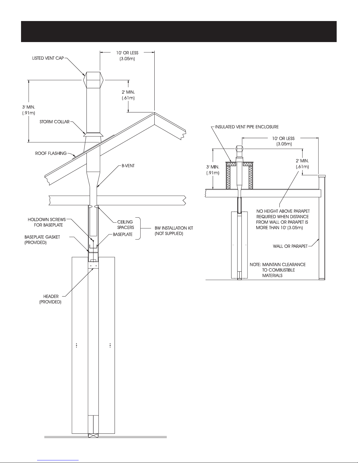
RECOMMENDED VENT CONFIGURATION
Note: No vent equipment supplied with furnace.
4" Oval (all parts purchase locally)
1. Type B-1 oval pipe
2. Single story type B-1 gas vents require a baseplate and one pair of
ceiling plate spacers.
3. Multi-story type B-1 gas vents require a baseplate, one pair of ceiling
plate spacers at the rst oor ceiling and one pair of re stop spacers
at each successive ceiling level.
Type B-W gas vent pipe is available for single story or multi-story
installations. Type B-W gas vent pipe is to be used with the
Listed base plate, ceiling plate spacers and re stop spacers.
Insulated Vent Enclosure
Gravity vented wall furnaces installed in buildings with at roofs can have
poor venting. The cold vent pipe will have a delay in proper venting and
cause the wall furnace to shut "off" by the vent safety switch. To prevent
delayed venting as well as condensation of ue products an insulated vent
enclosure is recommended.
Use Type B vent pipe and maintain at least a one inch (25mm) clearance
to combustibles.
Use metal thimble to protect vent pipe as it passes through combustibles.
Baseplate Gasket is factory installed on header. Baseplate attaches to header
with screws. B-vent snaps into and is attached to baseplate. Minimum
height of vent pipe must be six feet (1.8m) above header.
Stud space around gas vents must be free of obstructions and building paper.
Uninsulated Single-Wall Metal Pipe shall not be used outdoors in cold
climates for venting gas utilization equipment.
Attention: The main burner uses room air for combustion. As the gas/air
mixture is injected into the main burner, there is also the ow of dust and
lint particles into the main burner.
Dust and lint accumulation inside the main burner will result in a yellow main
burner ame and possible sooting inside the combustion chamber and vent
pipe. To clean main burner refer to Page 13, "Proper Main Burner Flame."
32039-1-0314Page 6
Page 7
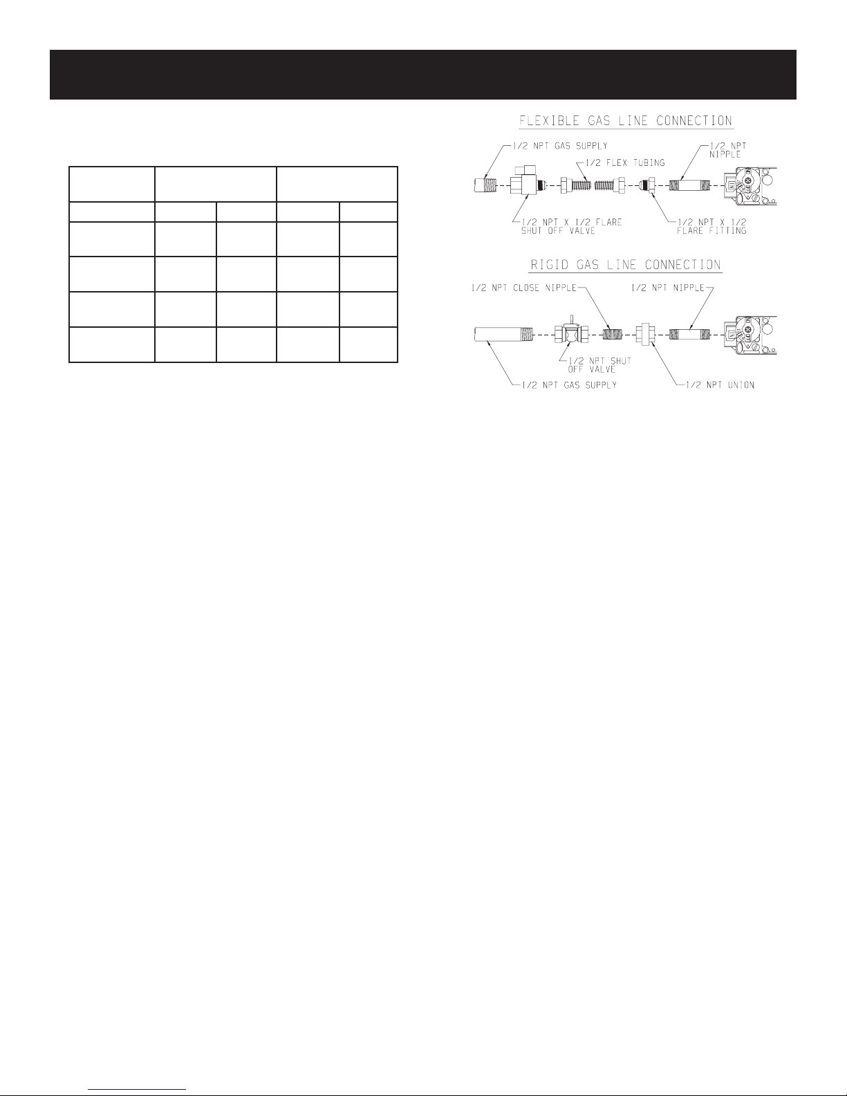
GAS SUPPLY
Check all local codes for requirements, especially for the size and
type of gas supply line required.
Recommended Gas Pipe Diameter
Pipe Length Schedule 40 Pipe
Inside Diameter
Nat. L.P. Nat. L.P.
0-10 feet
0-3 meters
10-40 feet
4-12 meters
40-100 feet
13-30 meters
100-150 feet
31-46 meters
Note: Never use plastic pipe. Check to conrm whether your local
codes allow copper tubing or galvanized.
Note: Since some municipalities have additional local codes, it is
always best to consult your local authority and installation code.
Check all local codes for requirements, especially for the size and
type of gas supply line required. On Natural gas lines less than 15'
(4.57m) long, use 1/2" pipe; on longer runs, use 3/4" iron pipe or
equal. On LP gas lines please consult LP gas supplier.
Installing a New Main Gas Cock
Each appliance should have its own manual gas cock.
A manual main gas cock should be located in the vicinity of the unit.
Where none exists, or where its size or location is not adequate,
contact your local authorized installer for installation or relocation.
Compounds used on threaded joints of gas piping shall be resistant
to the action of liqueed petroleum gases. The gas lines must be
checked for leaks by the installer. This should be done with a soap
solution watching for bubbles on all exposed connections, and if
unexposed, a pressure test should be made.
Neveruseanexposedametocheckforleaks.Appliancemust
be disconnected from piping at inlet of control valve and pipe
capped or plugged for pressure test. Never pressure test with
appliance connected; control valve will sustain damage!
A gas valve and ground joint union should be installed in the gas
line upstream of the gas control to aid in servicing. It is required by
the National Fuel Gas Code that a drip line be installed near the gas
inlet. This should consist of a vertical length of pipe tee connected
into the gas line that is capped on the bottom in which condensation
and foreign particles may collect.
1/2”
12.7mm
1/2”
12.7mm
1/2”
12.7mm
3/4”
19mm
3/8”
9.5mm
1/2”
12.7mm
1/2”
12.7mm
1/2”
12.7mm
Tubing, Type L
Outside Diameter
1/2”
12.7mm
5/8”
15.9mm
3/4”
19mm
7/8”
22.2mm
3/8”
9.5mm
1/2”
12.7mm
1/2”
12.7mm
3/4”
19mm
Figure 1
The use of the following gas connectors is recommended:
— ANS Z21.24 Appliance Connectors of Corrugated Metal Tubing
and Fittings
— ANS Z21.45 Assembled Flexible Appliance Connectors of Other
Than All-Metal Construction
The above connectors may be used if acceptable by the authority
having jurisdiction. The state of Massachusetts requires that a
exible appliance connector cannot exceed three feet in length.
Pressure Testing of the Gas Supply System
1. To check the inlet pressure to the gas valve, a 1/8" (3.175mm)
N.P.T. plugged tapping, accessible for test gauge connection,
must be placed immediately upstream of the gas supply
connection to the appliance.
2. The appliance and its individual shutoff valve must be
disconnected from the gas supply piping system during any
pressure testing of that system at test pressures in excess of
1/2 psig (3.5 kPa).
3. The appliance must be isolated from the gas supply piping
system by closing its individual manual shutoff valve during
any pressure testing of the gas supply piping system at test
pressures equal to or less than 1/2 psig (3.5 kPa).
Attention! If one of the procedures results in pressures in excess
of 1/2 psig (14" w.c.) (3.5 kPa) on the appliance gas valve, it will
result in a hazardous condition.
Checking Manifold Pressure
Both Propane and Natural gas valves have a built-in pressure
regulator in the gas valve. Natural gas models will have a manifold
pressure of approximately 3.5" w.c. (.871kPa) at the valve outlet
with the inlet pressure to the valve from a minimum of 4.5" w.c.
(1.120kPa) for the purpose of input adjustment to a maximum of
10.5" w.c. (2.614kPa) Propane gas models will have a manifold
pressure approximately 10.0" w.c. (2.49kPa) at the valve outlet
with the inlet pressure to the valve from a minimum of 11.0" w.c.
(2.739kPa) for the purpose of input adjustment to a maximum of
13.0" w.c. (3.237kPa).
A 1/8" (3.175mm) N.P.T. plugged tapping, accessible for test gauge
connection, is located on the outlet side of the gas control.
32039-1-0314 Page 7
Page 8

CLEARANCES
1. In selecting a location for installation, it is necessary to provide
adequate accessibility clearances for servicing and proper
installation.
2. Clearances to combustible surfaces are 4" (102mm) from sides,
12" (305mm) to top, 1 1/2" (38mm) from oor.
NOTE: Minimum distance of 1 1/2" (38mm) must also be maintained
VENTILATION AND COMBUSTION AIR
Wall furnaces shall be installed in a location in which the facilities
for ventilation permit satisfactory combustion of gas and proper
venting under normal conditions. In buildings of conventional frame,
brick, or stone construction without tight storm windows and doors,
inltration is normally adequate to provide air for combustion and
draft hood dilution.
from top surface of carpeting, tile, etc.
Where appliances are installed in conned and unconned spaces
within a building, the building being of unusually tight construction,
air for combustion and ventilation must be obtained directly from
outdoors or from such spaces that freely communicate with the
outdoors. Under these conditions, the conned and unconned
spaces shall be provided with two permanent openings, one near
the top of the enclosure and one near the bottom; each opening
shall have a free area of not less than one square inch (6.45cm2)
per 2,000 BTU (.6KW/H) per hour of total input.
LOCATION - ALL MODELS
Select a location near the center of the space to be heated. Overow
heat will circulate through doorways into adjacent rooms.
For large homes or spread-out oor plans, two or more furnaces are
recommended. Do not locate furnace where a door could swing
over the outer casing, or where circulation could be retarded by
furniture or cabinets.
Do not install in a closet, alcove or small hallway where the furnace
could be isolated by closing doors to the heated space.
When location is selected, check the walls, attic and roof to make
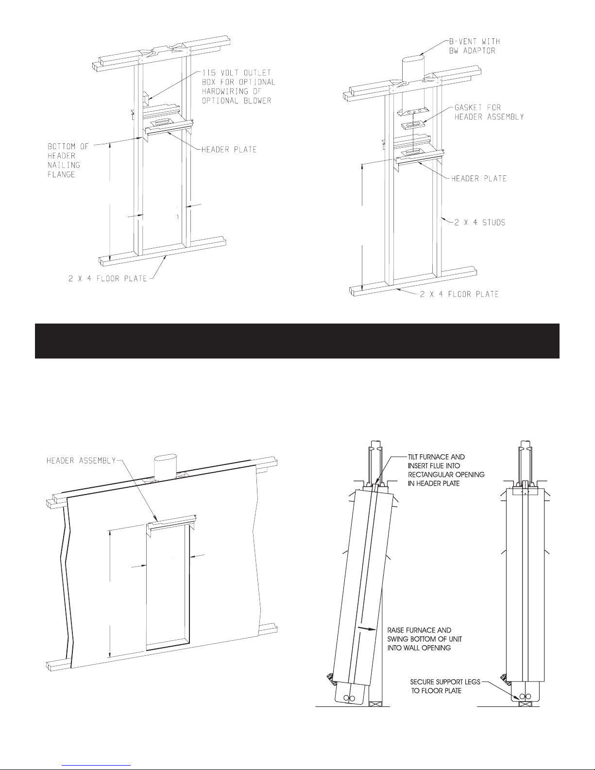
ROUGH-IN INSTRUCTIONS
Provide an opening in the wall 14 1/2" (368mm) wide and 66 1/8"
(168cm) high measured from top of oor plate (See Figure 2 and
Figure 3). Wall depth is to be 2" x 4" framing with 1/4" (6.5mm) to
5/8" (16mm) sheeting. Attach baseplate (not supplied with furnace)
to header plate with sheet metal screws at each end. Attach 4"
(102mm) oval, double wall vent pipe to baseplate. Attach enough vent
pipe so that when installed in wall opening the vent pipe will extend
above the ceiling plate by at least 6" (152mm). Install ceiling spacers
according to manufacturer's instructions. Two header extensions
are attached to the header plate. One header extension is welded
to the header plate and one header extension is screwed to the
header plate. To install header plate into wall opening remove the
header extension that is screwed to the header plate (2 screws).
sure there are no obstructions such as pipes, electric wiring, etc.,
which would interfere with the installation of the furnace or vent pipe.
NOTE: If Optional Blower is to be used, hard wiring must be
completed for the optional blower prior to installation of
header plate.
Insert header plate with attached 4" oval, double wall vent pipe
into wall opening. Position header plate at height shown in Figure
2. Locate rear edge of nailing ange at the back of the 2" x 4" stud
which will center the vent collar in the wall. Locate the angled edge
of header plate ush with the top of the wall opening. Nail header
plate to the wall studs. Replace and attach header extension onto
header plate with 2 screws.
32039-1-0314Page 8
Page 9
62 1/4”
(1581 mm)
14 ½”
(368 mm)
Figure 2
66 1/8”
(1679 mm)
WALL
OPENING
FINISHING INSTRUCTIONS
Figure 3
Plastering (Figure 4)
In new construction use only plain (not perforated) gypsum lath
around furnace and vent pipe so that plaster "Keys" will not project
into wall space.
Use wood strips nailed to inside of studs and top of bottom plate.
These must be removed before installation of furnace. Lath and
plaster against top projection of Header Plate.
Do not allow wall nish materials to project into furnace recess..
14 ½”
(368 mm)
66 1/8”
(1679 mm)
WALL
OPENING
Installing Furnace (Figure 5)
Clear the recess of all debris, and remove any wood plaster-grounds.
Stand the furnace on oor in front of wall opening.
Insert furnace ue into rectangular opening in header plate and
raise furnace carefully (see Figure 5). Swing bottom of furnace into
wall opening with back of legs ush with rear of oor plate. Secure
furnace support legs to the oor plate.
Figure 4
32039-1-0314 Page 9
Figure 5
Page 10
FINISHING INSTRUCTIONS (continued)
IMPORTANT — Avoid securing too tightly and disturbing the inner
casing. Do not try to force furnace into a wall opening which is
smaller than specied dimension.
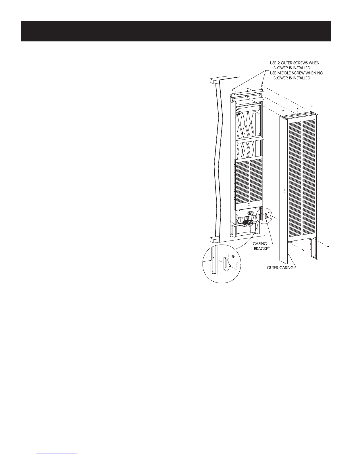
OUTER CASING (Figure 6)
1. Align 1 3/4" slot on casing bracket with bottom screw hole on
inner casing. Attach casing bracket to inner casing with one (1)
10 x 1/2" screws for each casing bracket. Do not completely
tighten screws at this time.
2. Place outer casing onto header.
Attention: Use center clearance hole on outer casing top for
attachment to header with one (1) 8 x 3/8" Phillips screw when
optional blower is not installed.
Attention: Use outside clearance holes on outer casing top
for attachment to header with two (2) 8 x 3/8" Phillips screws
when optional blower is installed.
3. Align clearance holes on outer casing bottom with screw holes
on casing brackets by adjusting slots on casing brackets.
4. Complete tightening casing bracket screws from Step 1 to inner
casing at this time.
5. Attach outer casing to casing brackets with two (2) 10 x 1-1/2"
screws.
INSTALLING CONTROL DOOR
Attach two washers supplied in hardware package to pivot pins
located at bottom of control door. Install control door to outer casing assembly.
Figure 6
32039-1-0314Page 10
Page 11

THERMOSTAT LOCATION (SG MODELS)
CAUTION — Do not run wire behind anges of Header Plate or in
any location where it might be damaged.
Millivolt wall thermostats are specially designed for use on self-
generating systems. They should never be used on line or low
voltage A.C. circuits.
Interior Wall — The thermostat should be installed on an inside
wall away from the furnace but in the same room.
It is important to use wire of a gauge proper for the length of the wire:
RECOMMENDED WIRE GAUGES
Maximum Length Wire Gauge
1' to 10' 18
10' to 25' 16
25' to 35' 14
Proper operation depends on a good pilot ame. The ame must
cover the top of the thermopile. Cleaning of the pilot orice and
burner may be required due to spiders.
System Check (Figure 7)
A millivolt meter is required to check the system. Millivolt readings
should be:
• Across the thermopile terminals, 400-450 millivolts with
thermostat OFF.
• Across the thermopile terminals, 150-250 millivolts with
thermostat ON.
• Across the thermostat wires at the valve, less than 30 millivolts
with thermostat ON.
• Across the thermostat wires at the thermostat, less than 5
millivolts with thermostat ON. (Dirty pilot or low pressure will
reduce readings.)
Figure 7
To conserve Gas: Turn off pilot when heater is not in use.
Connect thermostat wires to gas valve as shown in Figure 7.
32039-1-0314 Page 11
Page 12

GAS CONTROL KNOB SHOWN IN "OFF" POSITION
LIGHTING INSTRUCTIONS
FOR YOUR SAFETY READ BEFORE LIGHTING
WARNING:Ifyoudonotfollowtheseinstructionsexactly,areorexplosion
may result causing property damage, personal injury or loss of life.
A. This appliance has a pilot which must be lighted by hand.
When lighting the pilot, follow these instructions exactly.
B. BEFORE LIGHTING smell all around the appliance area
forgas.Besuretosmellnexttotheoorbecausesome
gasisheavierthanairandwillsettleontheoor.
WHAT TO DO IF YOU SMELL GAS
• Do not try to light any appliance.
• Do not touch any electrical switch;
do not use any phone in your building.
• Immediately call your gas supplier from a neighbor's
phone. Follow the gas supplier's instructions.
• Ifyoucannotreachyourgassupplier,calltheredepartment.
LIGHTING INSTRUCTIONS
1. STOP! Read the safety information above.
2. Set the thermostat to lowest setting (if applicable).
3. Turn off all electric power to the appliance (if applicable).
4. Remove control access panel (control door).
5. Push in gas control knob slightly and turn clockwise
to "OFF."
NOTE: Knob cannot be turned from "PILOT" to "OFF"
unless knob is pushed in slightly. Do not force.
6. Wait ten (10) minutes to clear out any gas. Then smell
forgas,includingneartheoor.Ifyousmellgas,STOP!
Follow "B" in the safety information above. If you don't
smell gas, go to the next step.
7. Find pilot - follow metal tube from gas control. The pilot
is mounted on front of main burner.
8. Turn gas control knob counterclockwise to "PILOT."
C. Use only your hand to push in or turn the gas control
knob. Never use tools. If the knob will not push in or
turnbyhand,don'ttrytorepairit;callaqualiedservice
technician.Forceorattemptedrepairmayresultinare
or explosion.
D. Do not use this appliance if any part has been under water.
Immediatelycallaqualiedservicetechniciantoinspect
the appliance and to replace any part of the control system
and any gas control which has been under water.
9. Push in control knob all the way and
hold in. Immediately light the pilot with
a match. Continue to hold the control
knob in for about one (1) minute after
the pilot is lit. Release knob and it will
pop back up. Pilot should remain lit. If
it goes out, repeat steps 5 through 9.
• If knob does not pop up when released, stop and imme-
diatelycallaqualiedservicetechnicianorgassupplier.
• If the pilot will not stay lit after several tries, turn the gas
control knob to "OFF" and call your service technician
or gas supplier.
10. Turn gas control knob counterclockwise to "ON."
11. Replace control access panel (control door).
12. Turn on all electric power to the appliance (if applicable).
13. Set thermostat to desired setting (if applicable).
TO TURN OFF GAS TO APPLIANCE
1. Set the thermostat to lowest setting.
2. Turn off all electric power (if applicable) to appliance if
service is to be performed.
3. Remove control access panel (control door).
4. Push in gas control knob slightly and turn clockwise
to "OFF." Do not force.
5. Replace control access panel (control door).
32039-1-0314Page 12
Page 13
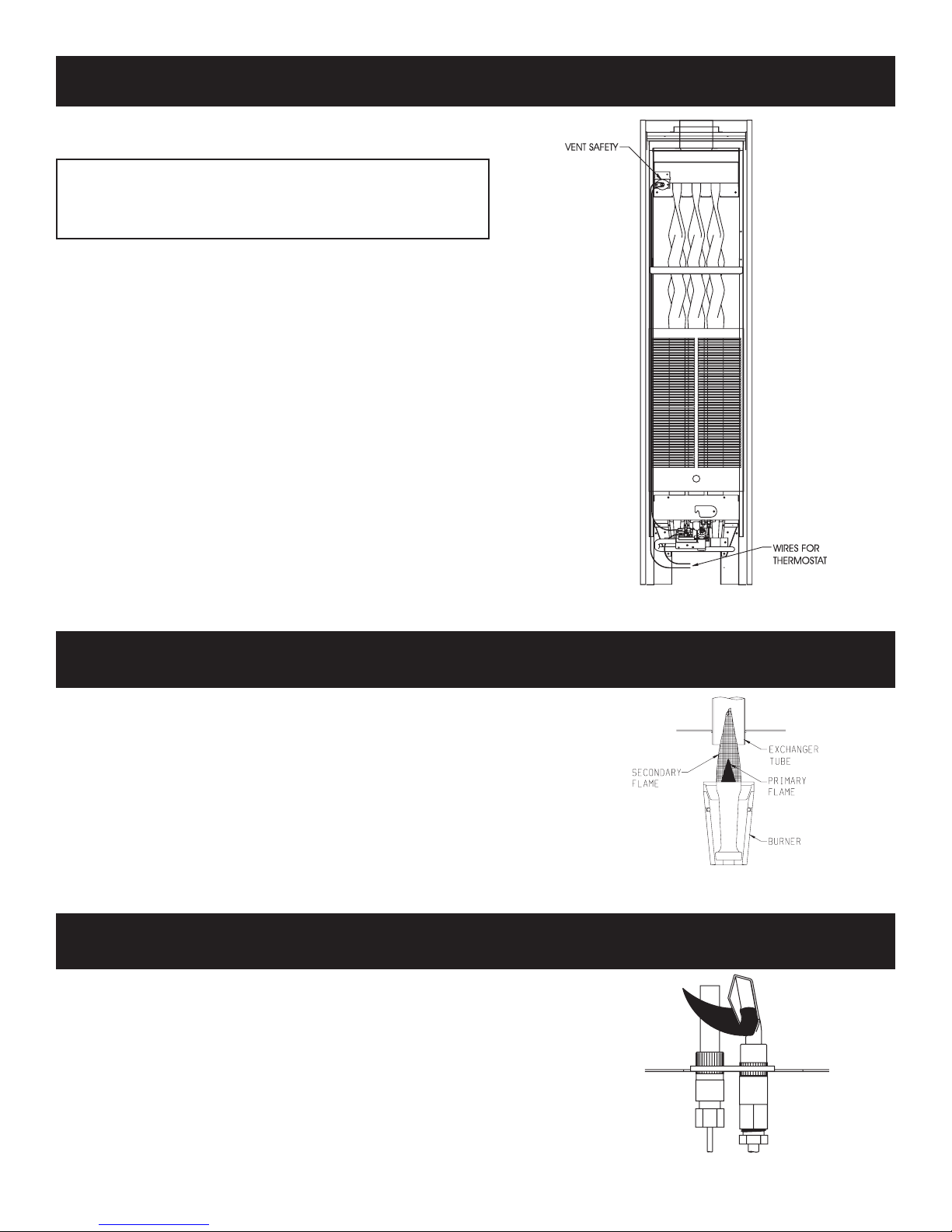
VENT SAFETY SHUTOFF SYSTEM
This appliance must be properly connected to a venting system. This
appliance is equipped with a vent safety shutoff system.
Warning: Operation of this wall furnace when not connected
to a properly installed and maintained venting system or
tampering with the vent safety shutoff system can result in
carbon monoxide (CO) poisoning and possible death.
This furnace is equipped with a manual reset vent safety switch. The
manual reset vent safety switch will cause gas ow to the main burner
to "shut off" due to improper venting or a blocked ue.
To reset the manual reset vent safety switch:
1. Remove outer casing.
2. Depress manual reset button. The manual reset vent safety switch
is located on the draft diverter.
3. Replace outer casing.
If the manual reset vent safety switch continues to "shut off" the gas
ow to the main burner a qualied service person must be contacted to
inspect for improper venting, blockage in the vent pipe or the manual
reset vent safety switch for being defective.
PROPER MAIN BURNER FLAME
The correct ame will be a short blue inner ame with a much larger light
blue outer ame. The burner does not have a primary air adjustment.
The ame will be proper if the factory-set pressure and orice are used.
After the furnace has begun operating, cleaning of the burner may be
needed for proper ame, examine at least 2 times per season.
To clean burner ports, disconnect the gas supply to the valve. Remove the
burner assembly from the combustion chamber. Remove pilot burner from
main burner and then remove the main burner. Force water into the ports
and blow dry with vacuum cleaner air, or low pressure compressed air.
PROPER PILOT FLAME
The correct ame will be blue, extending past the thermopile. The ame
will surround the thermopile just below its tip.
Natural gas pilots require adjusting when the inlet gas pressure is above
5" w.c. (1.245kPa). Remove the pilot cover screw on the control valve
and turn the adjustment screw clockwise to reduce ame. Replace
pilot cover screw to eliminate gas leaking at that control valve opening.
LP gas (propane) will not require adjustment.
After use, cleaning may be required for the proper ame.
Examine the pilot ame before and during each heating season.
Figure 8
Figure 9
32039-1-0314 Page 13
Figure 10
Page 14

TROUBLESHOOTING
GENERAL All furnaces have been re-tested to check for proper
operation. This includes main burner ame, pilot ame, and gas
control operation. If the furnace fails to function on initial installation,
it is advisable to re-check the following:
1. Inlet gas pressure.
2. Type of gas being used and that shown on the rating plate.
The Service Department at Empire Comfort Systems, Inc. may be
contacted to assist in servicing furnace.
ServicingthePilotandMainBurner,PilotOrice,Thermopile
andMainBurnerOrice
Disconnect the gas supply at the inlet to the control valve. Remove
the burner assembly to which the above components are attached.
Pilot Does Not Light
With air in the gas line, such as when the furnace is rst installed
or was "OFF" all summer, the pilot ame may be too lean to ignite
on the rst few trials. Turn the gas control knob to PILOT position
and depress the gas control knob. Hold the gas control knob down
to bleed the line;
1. Use lighter rod to light pilot with a match.
If Pilot Does Not Light By Any Means
1. Check gas control knob for being in the "Pilot" position.
2. Check pilot adjustment for being full open (counterclockwise
to open).
3. If gas is available in the supply tubing, the pilot orice and/
or pilot burner is probably restricted by a spider web. Clean
pilot assembly and relight.
If Pilot Does Not Remain "On" After Releasing Gas Control Knob
1. Follow instructions and hold gas control knob down longer
and harder.
2. Determine if pilot ame extends past thermopile; if not, adjust
pilot ame or clean pilot burner.
3. Replace thermopile if millivolt reading is less than 300 millivolts
when wall thermostat or remote bulb is turned OFF. Replace
gas control if magnet dropout millivolt reading is over 100
millivolts.
Pilot Outage During Normal Operation
1. Check input by manifold pressure gauge or gas meter.
2. Check millivolt output when furnace is in operation. If millivolt
output decreases during furnace operation gas control may
be defective.
Main Gas Valve Does Not Open When Thermostat Is Turned "On"
1. Check millivolt output of thermopile.
2. Thermostat wires may be broken.
3. Thermostat may be defective.
32039-1-0314Page 14
Page 15

PARTS LIST
ATTENTION: When ordering parts, it is very important that part number and description of part coincide.
INDEX PART
NO. NO. DESCRIPTION
1 WFA-115 HEADER GASKET
2 GWT-175
2 15756
3 GWT-184 INNER CASING ASSEMBLY
4 GWT-151 DIVERTER ASSEMBLY (2 REQUIRED)
5 GWT-020 FRONT SHIELD (2 REQUIRED)
6 GWT-077 HEAT SHIELD (2 REQUIRED)
7 GWT-177
8 GWT-186 CASING BRACKET (4 REQUIRED)
9 GWT-087
9 15739
10 R-885 NYLON WASHER (4 REQUIRED)
11 R-3763 MAGNET (4 REQUIRED)
12 DV-064 COVER PLATE (2 REQUIRED)
13 GWT-008
14 R-3046 VENT SAFETY SWITCH
15 R-3038-A ECO LEAD ASSEMBLY
16 26466 EXCHANGER ASSEMBLY - REAR
17 26465 EXCHANGER ASSEMBLY - FRONT
18 R-3036 PILOT - NAT
18 R-3037 PILOT - LPG
19 R-1054 THERMOPILE
20 GWT-096 BURNER BRACKET ASSEMBLY
HEADER ASSEMBLY
(INCLUDES NO. 1, GASKET) (USA)
HEADER ASSEMBLY (INCLUDES
NO. 1, GASKET) (CANADA)
CASING FRONT ASSEMBLY
(2 REQUIRED)
CASING DOOR ASSEMBLY
(2 REQUIRED) (USA)
CASING DOOR ASSEMBLY
(2 REQUIRED) (CANADA)
BURNER COMPARTMENT FRONT
(2 REQUIRED)
INDEX PART
NO. NO. DESCRIPTION
21 R-5245 GAS VALVE - NAT
21 R-5246 GAS VALVE - LPG
22 R-3031 BURNER (6 REQUIRED)
23 P-88-55
23 P-88-65
24 GWT-014
25 GWT-015
26 GWT-054
27 23906 VALVE SHIELD
28 23385
29 24752 LOWER SHIELD
30 29011 EXCHANGER TUBE ASSEMBLY
NOT
SHOWN
NOT
SHOWN
NOT
SHOWN
NOT
SHOWN
NOT
SHOWN
GWT-099 PILOT TUBING
R-3178
R-3179
R-734 MATCH HOLDER
GWT-190
BURNER ORIFICE - NAT (6
REQUIRED)
BURNER ORIFICE - LPG (6
REQUIRED)
AIR SHUTTER FRONT - LPG
(2 REQUIRED)
AIR SHUTTER REAR -
LPG (2 REQUIRED)
AIR SHUTTER BOTTOM -
LPG (2 REQUIRED)
CASING ASSEMBLY COMPLETE
(INCLUDES #7, #9 AND TWO #10)
PILOT ORIFICE
(HONEYWELL K14 .014 LPG ONLY)
PILOT ORIFICE
(HONEYWELL A26 .026 NAT ONLY)
HARDWARE PACKAGE (2
REQUIRED)
USE ONLY MANUFACTURER'S REPLACEMENT PARTS. USE OF ANY OTHER PARTS COULD CAUSE INJURY OR DEATH.
HOW TO ORDER REPAIR PARTS
Parts can be ordered only through your service person or dealer. For best results, the service person or dealer should order parts
through the distributor. Parts can be shipped directly to the service person/dealer.
All parts listed in the Parts List have a Part Number. When ordering parts, rst obtain the Model Number from the name plate on your
equipment. Then determine the Part Number (not the Index Number) and the Description of each part from the following appropriate
illustration and list. Be sure to give all this information.
Furnace Model Number Part Description
Furnace Serial Number Part Number
Type of Gas (Propane or Natural)
Do not order bolts, screws, washers or nuts. They are standard hardware items and can be purchased at any local hardware store.
Shipments contingent upon strikes, res and all causes beyond our control.
Empire Comfort Systems, Inc. Nine Eighteen Freeburg Ave. Belleville, Illinois 62222-0529
32039-1-0314 Page 15
Page 16

PARTS VIEW
28
7
5
6
4
8
9
10
1
2
3
4
5
14
15
6
29
12
30
13
22
23
24
25
26
16
20
19
18
22
26
17
23
21
8
25
30
13
12
24
27
11
7
10
9
32039-1-0314Page 16
Page 17

OPTIONAL REMOTE BULB CONTROL INSTALLATION INSTRUCTIONS
MODELS
GWT-25 RB, GWT-35 RB, GWT-50 RB
Note: The remote bulb control may be located on the left or
right side of the outer casing.
1. Remove remote bulb control from the shipping carton.
2. Remove outer casing assembly from shipping carton.
Note: If wall furnace is already installed, remove outer casing
from unit and lay on oor with front side down.
3. Attach wire assembly to remote bulb control.
4. Carefully unwind capillary wire on remote bulb control.
5. Remove three (3) hole plugs from left or right side of outer
casing where remote bulb control is to be installed.
6. Mount remote bulb control to inside of outer casting with two
(2) No. 6-32 x 1/4 screws.
Caution: Remote bulb wire routing is important. Wires
should be in proper location to avoid damage from being overheated. Incorrect routing of remote bulb control wires may result in damage to wires and incorrect operation of remote bulb
control. Follow these instructions and refer to the following
illustrations for proper wire routing.
7. If remote bulb control is located on the right side of the outer
casing, carefully bend or loop capillary wire around control.
This will enable the sensing bulb to be positioned at the bottom of the unit.
8. Secure sensing bulb on the inside, at the bottom, of the outer
casing with two (2) plastic clips.
9. Feed the wire assembly down along the inside of the outer
casing.
10. Use the third plastic clip to secure wire assembly and capillary
wire to the casing (approximately 24” (610mm) from bottom
of units).
11. Attach control knob to remote bulb control.
12. Install furnace according to instructions
in the Installation Instructions and Owner’s Manual.
Note: If wall furnace is already installed, secure outer casing
to unit.
13. Attach wire assembly to gas valve at the "TH" and "TH/TP"
terminals on the gas valve. If the wire assembly has two 1/4"
female connectors, the connectors should be cut off the wire
assembly. Strip and bare the wires and attach wires to the
"THERMO" terminals.
Note: This remote bulb control is connected to the gas valve
the same way as a wall thermostat. Any references made to
the thermostat in the lighting instructions would also apply to
the remote bulb control.
Gas Valve
32039-1-0314 Page 17
Part Number Description
R-1224 Remote Bulb Control
R-2499 Wire Assembly
R-1162 Control Knob
R-1720 Plastic Clip (3 Required)
R-1575 No. 6-32 x 1/4" (6mm) Screw (2 required)
Page 18

OPTIONAL BLOWER INSTALLATION INSTRUCTIONS
Installing Blower Using Three-Prong Plug
1. Install furnace according to Installation Instructions and Owner's
Manual.
2. Refer to Drawing for measurements to locate (2) mounting holes
on wall surface above furnace.
On Solid Wall
3. After locating mounting holes, attach (2) #10 x 1 1/2" screws provided
in blower kit into wall. Do not completely tighten screwheads to
wall, leave a 7/16" gap between screwheads and wall.
On Sheet Rock Wall
3. After locating mounting holes, drill (2) 5/16" diameter holes into
wall. Insert the (2) plastic expansion anchors into holes. Insert (2)
#10 x 1 1/2" screws provided in blower kit into (2) plastic expansion
anchors. Do not completely tighten screwhead to plastic expansion
anchors, leave a 7/16" gap between screwheads and plastic
expansion anchors. Refer to Figure 2.
4. At the top of outer casing remove (1) screw from center clearance
hole that attaches outer casing to header assembly. Also, remove
(2) screws that attach bottom of outer casing to inner casing.
5. Pull the outer casing forward approximately 1 inch away from wall
surface.
6. Remove (4) 8 x 3/8" screws that attach blower front to blower
housing.
Caution: When removing blower front be careful not to damage
motor coil wires. Damaged coil wires will disable blower function.
7. Position blower housing on top of header assembly and route
three-prong cord set between left side of outer casing and inner
casing.
Caution: When installing blower housing onto wall be careful motor
coil is not damaged.
Installing Blower With Hard Wiring
1. When facing the wall opening, install 120V electrical outlet junction
box inside wall opening on left wall stud approximately 12 inches
above header plate.
2. Refer to Drawing for measurements to locate access hole for
electrical wiring on wall surface.
3. After locating access hole, drill a 1/2" hole into wall.
4. Route enough eld wiring from 120V electrical outlet junction box
through 1/2" access hole in wall for connection to blower housing.
5. Install furnace according to Installation Instructions and Owner's
Manual.
6. Refer to Drawing for measurements to locate (2) mounting holes
on wall surface above the furnace.
On Solid Wall
7. After locating mounting holes, attach (2) #10 x 1 1/2" screws provided
in blower kit into wall. Do not completely tighten screwheads to
wall, leave a 7/16" gap between screwheads and wall.
On Sheet Rock Wall
7. After locating mounting holes, drill (2) 5/16" diameter holes into
wall. Insert (2) plastic expansion anchors into holes. Insert (2) #10
x 1 1/2" screws provided in blower kit into (2) plastic expansion
anchors. Do not completely tighten screwhead to plastic expansion
anchors, leave a 7/16" gap between screwheads and plastic
expansion anchors. Refer to Figure 2.
Caution: Blower cord set routing is important. Cord set should be in
proper location to avoid being overheated. Incorrect routing of cord
set may result in damage to cord set.
8. Replace the outer casing to the wall surface.
9. Attach outer casing to header assembly. Attention: The center
clearance hole will not be used. The two outside clearance holes
will be used to attach outer casing to header assembly, (1) screw
from Step 4 and (1) screw supplied in hardware package. Refer
to Figure 1.
Figure 1
10. Attach outer casing to inner casing with (2) screws from Step 4.
11. Align key hole slots on back of blower housing with the (2) screws
attached to wall. Position blower housing ush with wall surface
and on top of outer casing. Complete tightening blower housing
screws from Step 3 to wall.
12. Attach caps and plugs from blower housing and blower front.
13. Attach blower front to blower housing with (4) 8 x 3/8" screws from
Step 6.
14. Installation of optional blower assembly is completed.
Figure 2
8. Remove three prong cord set from blower housing.
9. Remove (4) 8 x 3/8" screws that attach blower front to blower
housing.
10. Position blower housing on top of header assembly.
11. Route 120V eld wiring into blower housing through cord set hole
on back of blower housing.
12. Refer to wiring diagram to make wiring connections inside blower
housing. Be sure to follow all local and National electrical codes
when making eld wiring connections.
13. Align key hole slots on back of blower housing with (2) screws
attached to wall. Position blower housing ush with wall surface
and on top of outer casing. Complete tightening blower housing
screws from Step 7 to wall.
14. Attach caps and plugs from blower housing and blower front.
15. Attach blower front to blower housing with (4) 8 x 3/8" screws from
Step 9.
16. Installation of optional blower assembly is completed.
32039-1-0314Page 18
Page 19

13”
(330 mm)
4 7/16”
(112.6 mm)
Figure 3
Fan Control
The automatic fan control is located on the bottom of the blower
assembly. The fan control is a nonadjustable, automatic type. The
fan control will require between 3 and 7 minutes of main burner
operation before the fan control "closes" and activates the blower.
The blower will continue to run between 3 and 7 minutes after the
main burner shuts off, before the fan control "opens" and deactivates
the blower.
Wiring
The appliance, when installed, must be electrically grounded in
accordance with local codes or, in the absence of local codes, with
the National Electrical Code, ANSI/NFPA 70 or Canadian Electrical
Code, CSA C22.1, if an external electrical source is utilized. This
appliance is equipped with a three-prong [grounding] plug for
your protection against shock hazard and should be plugged
directly into a properly grounded three-prong receptacle. Do
not cut or remove the grounding prong from this plug. For an
ungrounded receptacle, an adapter, which has two prongs and a
wire for grounding, can be purchased, plugged into the ungrounded
receptacle and its wire connected to the receptacle mounting screws.
With this wire completing the ground, the appliance cord plug can
be plugged into the adapter and be electrically grounded.
GWTB-2 WIRING DIAGRAM
WARNING:
Unplugging of blower accessory will not stop the heater
from cycling. To shut heater off: Turn temperature dial or
thermostat to lowest setting. Turn knob on gas control to
"OFF", depressing slightly. Do not force.
CAUTION: Label all wires prior to disconnection when servicing
controls. Wiring errors can cause improper and dangerous
operation. Verify proper operation after servicing.
Oiling
The blower motor does not have oiling holes. Do not attempt to oil
the blower motor.
32039-1-0314 Page 19
PARTS LIST
INDEX
NO.
PART NO. DESCRIPTION
1 R-2204 CORD SET
2 8720161 STRAIN RELIEF BUSHING
3 15888 BLOWER HOUSING ASSEMBLY
4 8520142 BRASS BUSHING (4 REQUIRED)
5 GWT-197 BLOWER SIDE (2 REQUIRED)
6 R-3085 WIRE ASSEMBLY
7 R-2503 FAN SWITCH
8 15887 BLOWER FRONT
9 8520141 RUBBER GROMMET (4 REQUIRED)
10 R-2804A BLOWER MOTOR
Page 20

SERVICE NOTES
EMPIRE
EMPIRE
Comfort Systems
Empire Comfort Systems Inc.
918 Freeburg Ave. Belleville, IL 62220
If you have a general question about our products, please e-mail us at
info@empirecomfort.com.
If you have a service or repair question, please contact your dealer.
www.empirecomfort.com
32039-1-0314Page 20
Page 21

MASTER PARTS DISTRIBUTOR LIST
To Order Parts Under Warranty, please contact your local Empire dealer. See the dealer locator at www.empirecomfort.
com. To provide warranty service, your dealer will need your name and address, purchase date and serial number, and the
nature of the problem with the unit.
To Order Parts After the Warranty Period, please contact your dealer or one of the Master Parts Distributors listed below.
This list changes from time to time. For the current list, please click on the Master Parts button at www.empirecomfort.com.
Please note: Master Parts Distributors are independent businesses that stock the most commonly ordered Original Equipment repair parts for Heaters, Grills, and Fireplaces manufactured by Empire Comfort Systems Inc.
Dey Distributing
1401 Willow Lake Boulevard
Vadnais Heights, MN 55101
Phone: 651-490-9191
Toll Free: 800-397-1339
Website: www.deydistributing.com
Parts: Heater, Hearth and Grills
East Coast Energy Products
10 East Route 36
West Long Branch, NJ 07764
Phone: 732-870-8809
Toll Free: 800-755-8809
Fax: 732-870-8811
Website: www.eastcoastenergy.com
Parts: Heater, Hearth and Grills
Victor Division of F. W. Webb Company
200 Locust Street
Hartford, CT 06114
Phone: 860-722-2433
Toll Free: 800-243-9360
Fax: 860-293-0479
Toll Free Fax: 800-274-2004
Websites: www.fwwebb.com & www.victormfg.com
Parts: Heater, Hearth and Grills
Able Distributors
2501 North Central Avenue
Chicago, IL 60639
Phone: 773-889-5555
Toll Free: 800-880-2253
Fax: 773-466-1118
Website: www. abledistributors.com
Parts: Heater
HOW TO ORDER REPAIR PARTS
Parts Not Under Warranty
Parts can be ordered through your Service Person, Dealer, or a Master Parts Distributor. See this page for the Master Parts Distributors list. For best results, the service person or dealer should order parts through the distributor. Parts can be shipped directly to the
service person/dealer.
Warranty Parts
Warranty parts will need a proof of purchase and can be ordered by your Service Person or Dealer. Proof of purchase is required for
warranty parts.
All parts listed in the Parts List have a Part Number. When ordering parts, rst obtain the Model Number and Serial Number from the
name plate on your equipment. Then determine the Part Number (not the Index Number) and the Description of each part from the following illustration and part list. Be sure to give all this information . . .
Appliance Model Number Part Description
Appliance Serial Number Part Number
Type of Gas (Propane or Natural)
Do not order bolts, screws, washers or nuts. They are standard hardware items and can be purchased at any local hardware store.
Shipments contingent upon strikes, res and all causes beyond our control.
32039-1-0314 Page 21
Page 22

WARRANTY
Empire Comfort Systems Inc. warranties this space heating product to be free from defects at the time of purchase and for the periods
specied below. Space heating products must be installed by a qualied technician and must be maintained and operated safely, in
accordance with the instructions in the owner’s manual. This warranty applies to the original purchaser only and is not transferable.
All warranty repairs must be accomplished by a qualied gas appliance technician.
Limited Lifetime Parts Warranty with a Five-Year Limited Labor Warranty – Combustion Chamber and Heat Exchanger
If the combustion chamber or heat exchanger (see parts list) fails because of defective workmanship or material, Empire will
repair or replace at Empire’s option.
Withinveyearsfromthedateofpurchase,Empirewillpayreasonablelabortohavethedefectivepartrepairedorreplacedat
Empire’s option.
Limited Five-Year Parts & Labor Warranty – All Other Components (Except Thermostats)
Shouldanypartfailbecauseofdefectiveworkmanshipormaterialwithinveyearsfromthedateofpurchase,Empirewill
repair or replace at Empire’s option.
Withinveyearsfromthedateofpurchase,EmpirewillpayreasonablelabortohavethatdefectrepairedatEmpire’soption.
Limited One-Year Parts Warranty – Remote Controls, Thermostats, Accessories, and Parts
Should any remote control, thermostat, accessory, or other part fail because of defective workmanship within one year from
the date of purchase, Empire will repair or replace at Empire’s option.
Duties of the Owner
The appliance must be installed by a qualied installer and operated in accordance with the instructions furnished with the
appliance.
A bill of sale, cancelled check, or payment record should be kept to verify purchase date and establish warranty period.
Ready access to the appliance for service
What Is Not Covered
Damages that might result from the use, misuse, or improper installation of this appliance.
Travel, diagnostic costs and freight charges on warranted parts to and from the factory.
Claims that do not involve defective workmanship or materials.
Unauthorized service or parts replacements.
Removal and reinstallation cost.
Inoperable due to improper or lack of maintenance.
How To Get Service
To make a claim under this warranty, please have your receipt available and contact your installing dealer. Provide the dealer
with the model number, serial number, type of gas, and purchase verication. The installing dealer is responsible for providing
service and will contact the factory to initiate any warranted parts replacements. Empire will make replacement parts available
at the factory. Shipping expenses are not covered.
If, after contacting your Empire dealer, service received has not been satisfactory, contact: Consumer Relations Department,
Empire Comfort Systems Inc., PO Box 529, Belleville, Illinois 62222, or send an e-mail to info@empirecomfort.com with
“Consumer Relations” in the subject line.
Your Rights Under State Law
This warranty gives your specic legal rights, and you may also have other rights, which vary from state to state.
EMPIRE
EMPIRE
Comfort Systems
Empire Comfort Systems Inc.
918 Freeburg Ave. Belleville, IL 62220
If you have a general question about our products, please e-mail us at
info@empirecomfort.com.
If you have a service or repair question, please contact your dealer.
www.empirecomfort.com
32039-1-0314Page 22
Page 23

INSTRUCTIONS POUR L’INSTALLATION
ET
MANUEL DU PROPRIÉTAIRE
FOURNAISE À AIR CHAUD
PAR GRAVITÉ
POUR MUR MITOYEN
MODÈLES
GWT-50-2(SG, RB)
Inst all ateu r: Laissez cette notice avec l’appareil.
Consommateur: Conservez cette notice pour
consultation ultériure.
AVERTISSEMENT: Si l’installation, l’usage
et l’entretien de ce produit ne sont pas faits
selon les instructions du fabricant, ce produit
peut vous exposer à des matières contenues
dans le carburant ou provenant de la combustion du carburant lesquelles peuvent causer
la mort ou de sérieuses maladies.
AVERTISSEMENT: Assurez vous de bien suivre les instructions données dans cette notice
pour réduire au minimum le risque d’incendie
ou d’explosion ou pour éviter tout dommage
matériel, toute blessure ou la mort.
— Ne pas entreposer ni utiliser d’essence ni d’autres
vapeurs ou liquides inammables dans le voisnage de cet appareil ou de tout autre appareil.
— QUE FAIRE SI VOUS SENTEZ UNE ODEUR DE
GAZ:
• Ne pas tenter d’allumer d’appareil.
• Ne touchez a aucun interrupteur. Ne pas vous
servir des téléphones se trouvant dans le bâtiment où vous vous trouvez.
• Appelez immédiatement votre fournisseur de
gaz depuis un voisin. Suivez les instructions
du fournisseur.
• Si vous ne pouvez rejoindre le fournisseur de
gaz, appelez le service des incendies.
— L’installation et l’entretien doivent être assurés
par un installateur ou un service d’entretien qual-
iéouparlefournisseurdegaz.
Page 23
Page 24

TABLE DES MATIÈRES
SECTION PAGE
Information Importante de Sécurité ..........................................................................3
Information de Sécurité pour les Utilisateurs de Propane ........................................ 4
Introduction ..............................................................................................................5
Spécications ...........................................................................................................5
Recommended Vent Conguration ..........................................................................6
Alimentation en Gaz .................................................................................................7
Espaces Libres .........................................................................................................8
Air de Ventilation et de Combustion .........................................................................8
Emplacement - Pour Tous les Modèles ....................................................................8
Instructions Sommaires .........................................................................................8-9
Instructions pour la Finition .................................................................................9-10
Emplacement du Thermostat (Modèles SG) .......................................................... 11
Instructions d'Allumage ..........................................................................................12
Le Système de Fermeture de Sûreté de l'Évent ....................................................13
Aspect Convenable de la Flamme du Brûleur Principal ......................................... 13
Aspect Convenable de la Flamme de la Veilleuse .................................................13
Détection des Défectuosités ................................................................................. 14
Listes des Pièces ...................................................................................................15
Façon de Commander les Pièces de Réparation ..................................................15
Vue des Pièces .....................................................................................................16
Instructions pour l'Installation de la Commande Lumineuse à Distance ................ 17
Instructions pour l'Installation de la Souferie Facultative .............................. 18-19
Notes de Service ....................................................................................................20
Liste Des Distributeurs de Pièces Principaux ........................................................21
Garantie .................................................................................................................22
32039-1-0314Page 24
Page 25

INFORMATION IMPORTANTE DE SÉCURITÉ
CECI EST UN APPAREIL DE CHAUFFAGE
NE PAS FAIRE FONCTIONNER CET APPAREIL SANS QUE LA PAROI EXTÉRIEURE SOIT INSTALLÉE.
• A cause des hautes températures, cet appareil doit être
situé dans un endroit non achalandé et loin des meubles
et des rideaux.
• Les enfants et les adultes doivent être avisés des dan-
gers des parois très chaudes et doivent rester loin pour
éviter les brûlures ou l’allumage des vêtements.
• Les petits enfants doivent être surveillés étroitement
lorsqu’ils sont dans le même appartement que l’appareil.
• Les vêtements ou d’autres matériaux inammables ne
doivent pas être placés sur ou près de l’appareil.
• Tout écran de sûreté qui est enlevé lors de la répara-
tion d’un appareil, doit être replacé avant de remettre
en marche cet appareil.
• Garder propre le brûleur et le compartiment de contrôle.
• L’installation et la réparation doivent être faites par une
PERSONNE QUALIFIÉE. L’appareil doit être inspecté
avant l’usage et au moins une fois par année, par une
personne qualiée. S’il y a un excès de poussière venant
du tapis, de la litterie, etc..., de fréquents nettoyages
seront requis. Il est impératif que les compartiments de
commandes, les brûleurs et les passages de circulation
d’air de l’appareil soient gardés propres.
• Ne rien mettre autour de la fournaise qui pourrait ob-
struer le débit de combustion et la ventilation d’air.
• Les matériaux combustibles, la gazoline ou les vapeurs
et liquides inammables ne doivent jamais être dans le
même endroit que le radiateur.
• Examiner périodiquement le système de ventilation et
remplacer les pièces défectueuses.
• Faire périodiquement une inspection visuelle de la veil-
leuse et des brûleurs. Nettoyer et remplacer les pièces
défectueuses.
• Ne pas utiliser cette fournaise s’il y a une pièce qui
a été en contact avec l’eau. Appeler immédiatement
un technicien qualié pour inspecter la fournaise et
remplacer toute pièce du système de commande et les
commandes de gaz qui ont été en contact avec l’eau.
• Cette fournaise ne doit pas être branchée à une chemi-
née servant à un autre appareil brûlant un combustible
solide.
32039-1-0314 Page 25
Page 26

INFORMATION DE SÉCURITÉ POUR LES UTILISATEURS DE PROPANE
Lepropaneestungazinammablequipeutcauserdesfeuxetdes
explosions. Dans son état naturel, le propane est inodore et sans
couleur. Peut-être que vous ne connaissez pas toutes les précautions
décrites ci-dessous? Elles peuvent vous protéger ainsi que votre
famille contre un accident. Lisez-les attentivement dès maintenant,
AVERTISSEMENT À PROPOS DE L’ODEUR DU PROPANE
Si une fuite de gaz survient, vous devriez sentir le gaz parce qu’il y a une odeur incorporée au propane.
C’est le signal que vous devez agir immédiatement.
• N’utiliser pas les interrupteurs électriques, n’allumer pas des allumettes ou n’utiliser pas le téléphone. Ne rien faire qui pourrait
enammer le gaz.
• Évacuer tout le monde du bâtiment, des véhicules et des lieux. Faire
ceci immédiatement.
• Fermer toutes les soupapes d’approvisionnement des réservoirs et
des bouteilles de gaz.
• Le propane est plus pesant que l’air et peut s’accumuler dans des
endroits bas comme les soubassements. Lorsque vous avez des raisons
de suspecter une fuite de gaz, n’allez pas dans les soubassements
ou les endroits bas. Attendez que les pompiers vous assurent de la
AUCUNE ODEUR DÉCELÉE - FAIBLE ODEUR
Il y a des personnes qui ne peuvent pas sentir très bien. Il y a des
personnes qui ne peuvent pas sentir l’odeur chimique mis dans le
gaz. Vous devez vérier si vous pouvez sentir cette odeur. Fumer peut
décroître votre capacité de sentir. Sentir une odeur pour un certain temps,
peut affecter votre sensibilité ou votre capacité de déceler cette odeur.
Quelquefois d’autres odeurs, dans le même endroit, peuvent masquer
l’odeur du gaz. Il y a des personnes qui ne peuvent pas sentir l’odeur du
gaz ou que leur attention est sur quelque chose d’autre. Penser à sentir
l’odeur du gaz peut faciliter la capacité de sentir.
L’odeur dans le propane est sans couleur et peut s’affaiblir selon
certaines circonstances. Par exemple, s’il y a une fuite souterraine, le
mouvement du gaz à travers le sol peut ltrer l’odeur. Aussi, l’odeur dans
le propane peut être exposée à l’oxydation. Cet affaiblissement peut
puis réexaminez les, point par point avec les membres de votre famille.
Un jour, lorsqu’il n’y aura pas une minute à perdre, la sécurité de chacun dépendra de votre savoir-faire. Si après avoir lu les informations
suivantes, vous pensez avoir besoin de plus amples informations,
s’il vous plaît contactez votre fournisseur de gaz.
sûreté de ces endroits avant d’y aller.
• Utiliser le téléphone de votre voisin et appeler les pompiers et une
personne entraînée avec le propane.
• Ne pas ouvrir les soupapes d’approvisionnement de gaz même si
vous ne le sentez plus. Ne retourner pas dans le bâtiment, sur les
véhicules ou sur les lieux.
• Finalement, laisser la personne qualiée et les pompiers vérier
les fuites de gaz. Laisser-les aérer les lieux avant d’y retourner. Les
personnes entraînées avec le propane devront réparer la fuite, vérier
et réallumer l’appareil au gaz, pour vous.
survenir s’il y a de la rouille à l’intérieur des réservoirs ou dans les tuyaux
de fer pour le gaz.
L’odeur de la fuite de gaz peut être adsorbée ou absorbée sur ou dans les
murs, maçonnerie et d’autres matériaux et tissus dans une chambre. Ceci
enlèvera une quantité de l’odeur du gaz, affaiblissant l’intensité de la senteur.
Le propane peut stratier dans un endroit fermé et l’intensité de l’odeur peut
varier à différents niveaux. Puisque le propane est plus pesant que l’air,
l’odeur peut être plus prononcée à un bas niveau. Toujours être sensible à
la moindre odeur de gaz. Si vous décelez une odeur, réagissez comme si
vous aviez une sérieuse fuite. Passez à l’action immédiatement en suivant
les informations précédentes.
• Apprendre à reconnaître l’odeur du propane. Votre distributeur de
propane peut vous donner un échantillon que vous grattez et sentez.
Utilisez-le pour savoir reconnaître l’odeur du propane. Si vous pensez
que votre gaz propane a une faible ou anormale odeur, appelez votre
distributeur.
• Si vous n’êtes pas qualié, n’allumer pas la veilleuse, n’effectuer pas
l’entretien ou n’ajuster pas les appareils fonctionnant au propane. Si
vous êtes qualié, soyez conscient de l’odeur du propane avant et
pendant que vous allumez la veilleuse, effectuez l’entretien ou faites
les ajustements.
• Quelquefois un soubassement ou une maison fermée a une senteur de
moisi qui peut dissimuler l’odeur de propane. N’essayez pas d’allumer
des veilleuses, d’effectuer l’entretien ou de faire des ajustements dans
des endroits où les conditions sont de telle sorte que vous ne pouvez
pas déceler l’odeur du propane en cas de fuite.
• L’affaiblissement d’odeur, attribuable à l’oxydation par la rouille ou
l’adsortion sur les parois des nouveaux réservoirs et bouteilles, est
possible. Par conséquent, les personnes doivent être particulièrement
prudentes lorsque de nouveaux réservoirs ou bouteilles sont mis en
service. L’affaiblissement d’odeur peut se produire dans les nouveaux
réservoirs ou dans les vieux réservoirs qui sont réinstallés, s’ils sont
remplis et inutilisés pour une longue période de temps. La formation
QUELQUES POINTS À RETENIR
de rouille à l’intérieur des bouteilles et des réservoirs qui ne sont
pas utilisés pour une longue période de temps, peut provoquer un
affaiblissement de l’odeur. Si vous pensez que de telles conditions
existent, un test de senteur de gaz est recommandé périodiquement.
Si vous avez des questions à propos de l’odeur du gaz, appelez
votre distributeur de propane. En toute circonstance, un test de
senteur périodique du gaz propane est une mesure de prudence.
• Si en aucun temps vous ne sentez pas l’odeur du propane et que vous
devriez, assumez que vous avez une fuite. Agissez immédiatement
selon les recommandations ci-dessus, décrivant les actions à suivre
en cas de décèlement de gaz propane.
• Si vous découvrez que le réservoir est complètement vide de gaz
(le réservoir n’a aucune pression de vapeur), fermez la soupape du
réservoir immédiatement. Si la soupape du réservoir reste ouverte,
le réservoir peut aspirer de l’air par les ouvertures, par exemple les
orices de la veilleuse. Si ceci survient, l’intérieur peut subir une
additionnelle formation de rouille. Si la soupape est restée ouverte,
considérez le contenant comme étant un nouveau réservoir. Soyez
toujours certain que le réservoir est sous pression de vapeur; fermez
la soupape du réservoir avant qu’il ne soit complètement vide et faites
le remplir.
32039-1-0314Page 26
Page 27

INTRODUCTION
Introduction
Lorsque la fournaise murale à air chaud est expédiée, elle est
prête à être installer entre les montants du mur 2" x 4" (51mm
x 102mm) et ceux-ci doivent avoir 16" (406mm) d’un centre à
l’autre centre. Toujours consulter le département de construction
de votre région en ce qui regarde les règlements, les codes ou
les ordonnances qui s’appliquent à l’installation d’une fournaise
murale à air chaud.
Instructions pour l’Installateur
1. Après l’installation, l’installateur doit laisser le manuel
d’instructions au propriétaire.
2. L’installateur doit demander au propriétaire de compléter et
poster la carte de guarantie qui est fournie avec la fournaise.
3. L’installateur doit expliquer au propriétaire la mise en marche
et le fonctionnement de la fournaise et du thermostat.
AVERTISSEMENT:
Tout changement fait à cette fournaise ou à ces
commandes peut être dangereux. Ceci est un appareil
de chauffage et si un panneau, une porte ou un dispositif
protecteur est enlevé pour l’entretien de cet appareil, il
doit être replacé avant de remettre en marche.
Information Générale
Ce radiateur est un modèle conformément certié avec
l'American National Standard / CSA Standard Z21.86 et
CSA 2.32 par Canadian Standards Association comme étant
une fournaise murale à air chaud, devant être installée en
accordance avec ces instructions.
Tout changement du modèle d’origine, installé autrement
que décrit dans ces instructions ou fonctionnant avec
un genre de gaz qui n’est pas indiqué sur la plaque
d’identication, est la responsabilité de la personne et
de la compagnie faisant ce changement.
Important
Toute la correspondance doit mentionner le numéro complet
du modèle et de la série et le genre de gaz.
Avis: Pendant le premier allumage de cette unité, la peinture
cuira et de la fumée se produira. Pour prévenir les détecteurs
de fumée de se déclencher, bien ventiler l’appartement dans
lequel l’unité est installée.
Installation dans les Garages Résidentiels
Tous les équipements dans les garages résidentiels employant
du gaz, doivent être installés de façon à ce que les brûleurs
et les appareils pour allumer les brûleurs doivent être situés
à au moins 45.7cm au dessus du plancher.
Tous ces équipements doivent être situés ou protégés de façon
à ce qu’un véhicule en se déplaçant ne puisse les endommager.
Agenced’InstallationQualiée
L’installation et le remplacement des tuyaux à gaz, des
équipements ou accessoires, la réparation et l’entretien de
l’équipement doivent être faits seulement par une agence
qualiée. Le terme “agence qualiée” signie tout individu,
rme, corporation ou compagnie qui est, en personne ou par
un représentant, engagé et responsable de: (a) l’installation
ou le remplacement des tuyaux à gaz, ou (b) la connexion,
l’installation, la réparation ou l’entretien de l’équipement, qui
possède l’expérience nécessaire en ce genre de travail, est
familié avec les précautions requises et s’est conformé à toutes
les exigences de l’autorité ayant juridiction.
L’installation doit être conforme aux codes locaux. Dans
l’absence de codes locaux, l’installation doit se conformer avec
National Fuel Gas Code ANSI Z223.1/NFPA 54* Natural Gas
and Propane Installation Code, CSA B149.1.
* Disponible chez American National Standards Institute, Inc., 11 West 42nd
St., New York, N.Y. 10036.
Hautes Altitudes
Pour des altitudes/élévations au dessus de 2,000' (610m), les
puissances d’entrée devront être réduites de 4% pour chaque
1,000' (305m) au dessus du niveau de la mer. Hautes Altitudes
au Canada pour les endroits ayant une élévation au dessus
du niveau de la mer entre 2,000' (610m) et 4,500' (1370m),
la pression doit être diminuée de 3.5" w.c. (.871kPa) à 3.0"
w.c. (.747kPa) pour le gaz naturel et de 10.0" w.c. (2.49kPa)
à 8.0" w.c. (1.992kPa) pour le gaz propane.
Modèle GWT-50
Puissance d’entrée BTU/HR (KW/H) 50,000 (14.7)
Hauteur 66 1/8" (1679mm)
Largeur 16" (406mm)
Profondeur (hors du mur) 6" (152mm)
Tuyau d’entrée de gaz 1/2" (13mm)
Tuyau d’évacuation ovale de type B 4" (102mm)
Accessoires pour les fournaises ci-dessus
Assemblage de la souferie GWTB-2
GWT-50 (SG,RB) est une fournaise pour MUR MITOYEN. L’air chaud se décharge dans deux pièces qui partagent le même mur.
32039-1-0314 Page 27
SPÉCIFICATIONS
Page 28

CAPUCHON D'ÉVENT
ENREGISTRÉ
MINIMUM 10'
(3.05m) OU
MOINS
ENTRETOISE
DU `PLAFOND
ENSEMBLE
D'INSTALLATION BW
(PAS FOURNI)
PLAQUE DE
BASE
COLLECTEUR
(FOURNI)
JOINT D'ÉTANCHÉITÉ
POUR LA PLAQUE DE BASE
(FOURNI)
VIS DE MAINTIEN
POUR LA PLAQUE DE
BASE
TUYAU
D'ÉVENT -B
MINIMUM
2' (.61m)
COLLET DE
TEMPÊTE
BANDE DE
SOLIN POUR LE
TOIT
MINIMUM
3' (.91m)
ENCEINTE ISOLÉE POUR
TUYAU D'ÉVACUATION
ENCEINTE ISOLÉE POUR
TUYAU D'ÉVACUATION
10' (3.05m)
MINIMUM
OU MOINS
2' (.61m)
MINIMUM
AUCUNE HAUTEUR AU DESSUS
DU PARAPET EST EXIGÉE
LORSQUE LA DISTANCE AU MUR
OU AU PARAPET EST PLUS DE
10' (3.05m)
MUR OU PARAPET
NOTE: MAINTENIR UN ESPACE
LIBRE AUX MATÉRIAUX
COMBUSTIBLES
3' (.91m)
MINIMUM
CONFIGURATION RECOMMANDÉE POUR L’ÉVACUATION
NOTE: Aucun matériel d’évacuation est fourni avec l’appareil.
Ovale de 4" (102mm) (toutes les pièces sont achetées localement)
1. Tuyau ovale de type B-1
2. Les tuyaux d’évacuation de type B-1 pour un étage exigent une plaque de base et
une paire d’entretoises pour le plafond.
3. Les tuyaux d’évacuation de type B-1 pour plusieurs étages exigent une plaque
de base, une paire d’entretoises pour le plafond que vous installez au plafond du
premier étage et une paire d’entretoises pare-feu pour tous les plafonds successifs.
Le tuyau à gaz d’évacuation de type B-W est disponible pour les installations
d’un étage ou de plusieurs étages. Le tuyau à gaz d’évacuation de type B-W
doit être utilisé avec la plaque de base certiée, les entretoises du plafond
et les entretoises à pare-feu.
Enceinte Isolée de l’Évent
Les fournaises murales à air chaud par gravité installées dans des bâtiments ayant un toit plat,
peuvent avoir une évacuation inadéquate. Un délai de l’évacuation adéquate se fera lorsque
le tuyau d’évacuation est froid par conséquent l’interrupteur de sûreté de l’évent “fermera” la
fournaise murale. Pour prévenir le délai de l’évacuation aussi bien que la condensation dans
les conduits d’évacuation, nous recommandons d’isoler l’enceinte d’évent.
Utiliser les tuyaux d’évacuation de type B et garder un espace libre d’au moins 1" (2.54cm)
aux combustibles.
Utiliser une bague en métal pour protéger les tuyaux d’évacuation lorsqu’ils passent à travers
les combustibles.
L’installation du joint d’étanchéité de la plaque de base sur le collecteur est faite à l’usine. La
plaque de base est attachée au collecteur avec des vis. L’évent-B s’insère avec un déclic et
est attaché à la plaque de base. La hauteur minimum du tuyau d’évacuation doit être de 6'
(1.82m) au dessus du collecteur.
Aucune obstruction ou aucun papier de construction doit être dans l’espace entre les montants
où les tuyaux d’évacuation passent.
Les tuyaux de métal à simple paroi non-isolés ne doivent pas être utilisés dans les endroits
à climat froid pour évacuer les gaz d’un appareil fonctionnant au gaz.
Attention ! Le brûleur principal utilise l’air ambiant pour la combustion. Lorsque le mélange
gaz/air est injecté dans le brûleur principal, des particules de poussières circuleront aussi
dans le brûleur principal.
Une accumulation de poussières dans le brûleur principal occasionnera la amme du brûleur
principal à devenir jaune et possiblement une accumulation de suie dans la chambre de combustion et dans le tuyau d’évacuation. Pour nettoyer le brûleur principal référez à la Page 13,
“Flamme convenable du brûleur principal”.
32039-1-0314Page 28
Page 29

ALIMENTATION EN GAZ
CONNEXION D’UNE LIGNE DE GAZ FLEXIBLE
Vérier tous les codes locaux pour répondre aux exigences,
spécialement pour la grandeur et le genre de ligne requise pour
l’alimentation de gaz.
Le Diamètre recommandé de tuyau de gaz
Longuer de
tuyau
0-10 feet
0-3 meters
10-40 feet
4-12 meters
40-100 feet
13-30 meters
100-150 feet
31-46 meters
Note: Ne jamais utiliser des tuyaux de plastique. Assurez-vous que les
codes locaux permettent les tuyaux de cuivre ou galvanisés.
Note: Étant donné que certaines municipalités ont des codes locaux
additionnels, il est toujours préférable de consulter votre autorité locale
et le code d’installation.
Installation d'un Nouveau Robinet Principal pour le Gaz
Chaque appareil doit avoir son propre robinet manuel de gaz.
Un robinet manuel principal doit être situé près de l’appareil. S’il n’y en
a pas ou si la grosseur ou l’emplacement est inadéquat, contacter votre
installateur autorisé pour l’installation ou pour changer l’emplacement.
Les composantes employées sur les joints letés des tuyaux doivent
être résistantes à l’action des gaz de pétrole liquéés. La canalisation
de gaz doit être vériée par l’installateur pour des possibilités de fuites.
Ceci doit être fait sur toutes les connexions exposées avec une solution
savonneuse. Surveiller pour la formation de bulles. Si les connexions
ne sont pas exposées, un test de pression doit être fait.
Nejamaisemployeruneammepourvérierlesfuites.Lorsd’un
test de pression, le tuyau d’arrivée de la valve de commande doit
être débranché de l’appareil et bouché. Ne jamais faire un test de
pression lorsque l’appareil est branché; la valve de commande
peut être endommagée!
Pour aider à l’entretien, une valve à gaz et un raccord horizontal doivent
être installés sur la ligne de gaz en amont du contrôle de gaz. Le National
Fuel Gas Code exige qu’une ligne d’égouttage soit installée près de
l’entrée de gaz. Ceci doit consister en une longueur de tuyau vertical
qui sera raccordé par un T sur la ligne de gaz et terminé au bas par un
bouchon. La condensation et les particules étrangères s’y amasseront.
Le plan 40 tuyau
diameter d’intérieur
Les tuyaux, Taper L
Hor du Diamétre
Nat. LP Nat. LP
1/2”
2.7mm
1/2”
12.7mm
1/2”
12.7mm
3/4”
19mm
3/8”
9.5mm
1/2”
12.7mm
1/2”
12.7mm
1/2”
12.7mm
1/2”
12.7mm
5/8”
15.9mm
3/4”
19mm
7/8”
22.2mm
3/8”
9.5mm
1/2”
12.7mm
1/2”
12.7mm
3/4”
19mm
ALIMENTATION DE GAZ ½
TUBE FLEXIBLE ½
½ NPT X½SOUPAPE DE
FERMETURE ÉVASÉE
CONNEXION D’UNE LIGNE RIGIDE
MAMELONG FERMɽNPT MAMELON NPT
SOUPAPE DE
FERMETURE½NPT
ALIMENTATION DE GAZ½NPT
Figure 1
L’emploi des connexions de gaz suivantes est recommandé.
— ANS Z21.24 Connexions d’appareil de tuyaux et de raccords en
métal ondulé.
— ANS Z21.45 Connexions exibles d’appareil autre qu’en métal.
Les connexions ci-dessus peuvent être utilisées si elles sont acceptées
par les autorités ayant juridiction. Les connexions ci-dessus peuvent
être utilisées si elles sont acceptées par les autorités ayant juridiction.
L’État de Massachusetts exige qu’une connexion exible d’un appareil
n’excède pas une longueur de trois pieds.
MAMELON
½ NPT X½RACCORD ÉVASÉ
RACCORD½NPT
Test de Pression du Système d'Alimentation de Gaz
1. Pour vérier la pression d’arrivée à la valve de gaz, une bonde N.P.T.
de 1/8" (3.175mm), accessible pour vérier le jaugeage des con-
nexions, doit être située immédiatement en amont de la connexion
d’alimentation de gaz de l’appareil.
2. Pendant un test de pression du système d’alimentation de gaz,
l’appareil et sa valve de fermeture doivent être débranchés si une
pression supérieure à 1/2 psig (3.5kPa) est employée.
3. Pendant un test de pression du système d’alimentation de gaz, si
une pression égale ou inférieure à 1/2 psig (3.5kPa) est employée,
l’appareil doit être isolé du système d’alimentation de gaz en fermant
sa propre valve de fermeture manuelle.
Attention! Si une des procédures ci-dessus occasionne une pression
supérieure à 1/2 psig (3.5kPa) sur la valve de gaz de l’appareil, une
situation dangereuse s’en suivra.
VérierlesPressionsdeGaz
Un régulateur de pression est incorporé dans la valve de gaz propane
et celle de gaz naturel.
Les modèles pour le gaz naturel auront des pressions de gaz approximativement de 3.5" w.c (.871kPa) à la sortie de la valve et une
pression d’entrée à la valve d’un minimum de 4.5" w.c. (1.120kPa) pour
permettre l’ajustement à l’entrée, allant à un maximum de 10.5" w.c.
(2.614kPa). Les modèles pour le gaz propane auront des pressions de
gaz approximativement de 10.0" w.c.(2.49kPa) à la sortie de la valve et
une pression d’entrée à la valve d’un minimum de 11.0" w.c. (2.74kPa)
pour permettre l’ajustement à l’entrée, allant à un maximum de 13.0
w.c. (3.24kPa).
Une bonde N.P.T. de 1/8" (3.175mm), accessible pour vérier le jaugeage
des connexions, est située sur le côté de la sortie de la commande de gaz.
32039-1-0314 Page 29
Page 30

ESPACES LIBRES
1. En choisissant un emplacement, il est nécessaire de fournir
l’espace libre adéquat pour l’accès à l’installation et à l’entretien.
2. Les espaces libres aux surfaces combustibles sont de 4" (102mm)
pour les côtés, 12" (305mm) pour le dessus et 1 1/2" (38mm)
pour le plancher.
NOTE: Une distance minimum de 1 1/2" (38mm) doit aussi être
AIR DE VENTILATION ET DE COMBUSTION
Les fournaises murales doivent être installées dans un endroit où la
facilité de la ventilation permet une combustion de gaz satisfaisante
et un échappement convenable sous des conditions normales. Dans
les bâtiments de construction conventionnelle, de brique ou de pierre
sans fenêtre et porte étanche, l’inltration est normalement adéquate
pour fournir l’air pour la combustion et la dilution du coupe-tirage.
EMPLACEMENT- POUR TOUS LES MODÈLES
Choisir un emplacement près du centre de l’espace à être chauffé.
Le surplus de chaleur circulera dans les chambres contiguëes par
les encadrements de porte.
Pour les grandes maisons ou des surfaces étendues de plancher,
nous recommandons deux ou plusieurs fournaises. Ne placer pas
une fournaise près d’une porte qui en s’ouvrant frapperait la paroi
extérieure de la fournaise ou près d’un meuble ou une armoire qui
ralentirait la circulation.
Ne pas installer dans un garde-robe, une alcôve ou un petit passage
où des portes fermées peuvent isolées la fournaise de l’endroit à
être chauffé.
Lorsque l’emplacement est choisi, vérier les murs, le grenier et
maintenue pour le dessus des tapis, tuiles, etc.
Lorsque les appareils sont installés dans des endroits connés et
ouverts d’un bâtiment lequel est exceptionnellement étanche, l’air
de combustion et de ventilation doit être obtenu directement de
l’extérieur ou d’un espace qui communique librement avec l’extérieur.
Sous ces conditions, les endroits connés et ouverts doivent être
pourvus de deux ouvertures permanentes, une près du dessus de
l’enceinte et une près du dessous; chaque ouverture doit avoir un
espace libre pas moindre que 6.45cm carré par 2,000 Btu (.6KW/H)
d’entrée totale.
le toit pour être certain qu’il n’y a pas d’obstruction telles que des
tuyaux, des ls électriques, etc., lesquels entraveraient l’installation
de la fournaise ou le tuyau d’évacuation.
Note: Si la souferie facultative est utilisée, l’installation électrique
permanente de la souferie facultative doit être complétée avant
d’installer la plaque collectrice.
INSTRUCTIONS SOMMAIRES
Plaque collectrice et tuyau d’évacuation (Figure 1 et Figure 2)
Faites une ouverture dans le mur d’une largeur de 14 1/2" (368mm)
et d’une hauteur de 66 1/8" (168cm), en mesurant à partir du dessus
de la lambourde (Voir Figure 2 et Figure 3). Lӎpaisseur du mur
consistera d’une construction de 2" x 4" (51mm X 102mm) avec une
tôle de 1/4" (6.5mm) à 5/8" (16mm). Assembler la plaque de base
(pas fournie avec la fournaise) à la plaque collectrice en utilisant
des vis à tôle à chaque extrémité. Attachez un tuyau d’évacuation
oval de 4" (102mm) et à double parois à la plaque de base. Assurezvous que vous aurez assez de longueur de tuyau d’évacuation de
façon que lorsqu’il sera installé dans l’ouverture murale, le tuyau
d’évacuation s’allongera d’au moins 6" (152mm) au-dessus de la
plaque du plafond. Installez les entretoises du plafond en suivant les
instructions du manufacturier. Deux extensions sont attachées à la
plaque collectrice. Une extension est soudée à la plaque collectrice
et l’autre extension est vissée à la plaque collectrice. Pour installer
la plaque collectrice dans l’ouverture murale, vous devrez enlever
l’extension qui est vissée àla plaque collectrice (2 vis). Insérez la
plaque collectrice avec le tuyau d’évacuation oval de 4" (102mm) et
à double parois dans l’ouverture murale. Mettez en place la plaque
collectrice à la hauteur représentée à la Figure 2. Trouvez le bord
arrière du rebord cloué à l’arrière du montant de 2" x 4" (51mm x
102mm) lequel centrera le collet de l’évent dans le mur. Placez le
rebord angulaire de la plaque collectrice de niveau avec le dessus
de l’ouverture murale. Clouez la plaque collectrice aux montants.
Replacez et vissez l’extension sur la plaque collectrice avec 2 vis.
32039-1-0314Page 30
Page 31

BAS DU REBORD
LAMBOURDE
CLOUÉ DU
COLLECTEUR
INSTALLATION ÉLECTRIQUE
PERMANENTE FACULTATIVE
D’UNE PRISE DE COURANT
115VOLT POUR LA
SOUFFLERIE FACULTATIVE
PLAQUE COLLECTRICE
ÉVENT BAVEC UN
ADAPTATEUR BW
JOINT D’ÉTANCHÉITÉ POUR
L’ENSEMBLE COLLECTEUR
62 ½”
(1581 mm)
14 ½”
(368 mm)
2”x4” (51mmx102mm)
Figure 2
INSTRUCTIONS POUR LA FINITION
Plâtrage (Figure 4)
Dans une nouvelle construction utiliser seulement des lattes de gypse
uni (non perforée) autour de la fournaise et du tuyau d’évacuation
ainsi les “Rappointis” du plâtre ne sortiront pas dans le trou du mur.
Utiliser des lattes de bois clouées à l’intérieur des montants et sur le
dessus de la plaque du bas. Celles-ci doivent être enlevées avant
d’installer la fournaise. Latter et plâtrer autour de la partie supérieure
de la projection de la plaque collectrice.
Ne laisser aucun matériel de la nition du mur dépasser dans la
cavité de la fournaise.
ENSEMBLE
COLLECTEUR
PLAQUE COLLECTRICE
66 1/8”
(1679 mm)
OUVERTURE
MURALE
LAMBOURDE 2”x4” (51mmx102mm)
MONTANTS 2”x4”
(51mmx102 mm)
Figure 3
le sol. Placer la fournaise sur le plancher devant l’ouverture murale.
Insérer le tuyau d’évacuation de la fournaise dans l’ouverture
rectangulaire dans la plaque collectrice et soulever la fournaise
soigneusement. (Voir Figure 5). Basculer le bas de la fournaise
dans l’ouverture murale en ayant l’arrière des pattes à eur avec
l’arrière de la lambourde. Fixer les pattes de support de la fournaise
à la lambourde.
BASCULERLA
FOURNAISEETINSÉRER
LE TUYAU
D'ÉVACUATION DANS
L'OUVERTURE
RECTANGULAIREDANS
LA PLAQUE
COLLECTRICE
14 ½”
(368mm)
66 1/8” (1679 mm)
OUVERTURE
MURALE
Figure 4
Installer la Fournaise (Figure 5)
Nettoyer la cavité de tous les débris et enlever le plâtre et le bois sur
32039-1-0314 Page 31
SOULEVER LA
FOURNAISE AND
POUSSER LE BAS DE
L'UNITÉ DANS
L'OUVERTURE MURALE
FIXER LES PATTES DE
SUPPORTÀ LA
LAMBOURDE
Figure 5
IMPORTANT
Éviter de xer la fournaise trop serrée et de pertuber la paroi intérieure.
N’essayer pas de forcer la fournaise dans une ouverture murale qui
serait plus petite que les dimensions mentionnées.
Page 32

INSTRUCTIONS POUR LA FINITION (SUITE)
PAROI EXTÉRIEURE (Figure 6)
1. Aligner les encoches de 1 3/4" du support de la paroi avec
les trous de vis qui sont au bas de la paroi intérieure. Attacher le support de la paroi avec la paroi intérieure avec
une (1) vis #10 x 1/2" pour chaque support de la paroi.
Ne serrez pas les vis complètement à ce moment.
2. Placer la paroi extérieure sur le collecteur.
Attention: Utiliser le trou libre au centre supérieur de la
paroi extérieur pour attacher le collecteur avec une (1) vis
Phillips #8 x 3/8" lorsquelasouferiefacultativen’est
pas installée.
Attention: Utiliser les trous libres extérieurs de la partie
supérieure de la paroi extérieure pour attacher le collecteur
avec deux (2) vis Phillips #8 x 3/8" lorsquelasouferie
facultative est installée.
3. Aligner les trous libres au bas de la paroi extérieur avec
les trous de vis qui sont sur les supports de la paroi en
ajustant les encoches sur les supports de la paroi.
4. Maintenant, visser complètement les vis du support de la
paroi que vous avez installées à l’Étape 1 avec la paroi
intérieure.
5. Attacher la paroi extérieure avec les supports de la paroi
en utilisant deux (2) vis #10 x 1 1/2".
INSTALLER LA PORTE DE COMMANDE
Attacher deux rondelles (fournies avec fournaise) aux goupilles situées au bas de la porte de commande. Installer la
porte de commande à l’assemblage des parois extérieures.
LORSQUE LA SOUFFLERIE EST
INSTALLÉE, UTILISER LES 2 VIS
UTILISER LA VIS DU MILIEU LORSQUE
LA SOUFFLERIE N’EST PAS INSTALLÉE.
SUPPORT DE
LA PAROI
EXTÉRIEURES.
PAROI EXTÉRIEURE
Figure 6
32039-1-0314Page 32
Page 33

EMPLACEMENT DU THERMOSTAT (MODÈLES SG)
ATTENTION — Ne placer pas des ls électriques derrière les
rebords de la plaque collectrice ou quelque part où ils seraient
endommagés.
Les thermostats muraux sont conçus pour l’usage d’un système
auto-générateur. Il ne doivent jamais être utilisés sur un circuit
en ligne ou un circuit de bas voltage de courant alternatif.
Mur intérieur — Le thermostat doit être installé sur un mur
intérieur, éloigné de la fournaise mais dans le même appartement que celle-ci.
Il est important d’employer le ll d’un mesure appropriée pour
la longueur du l:
MESURES RECOMMANDÉES DE FIL
Longueur Maximum Mesure de Fil
1' to 10' 18
10' to 25' 16
25' to 35' 14
Le bon fonctionnement dépend d’une amme adéquate de la
veilleuse. La amme doit recouvrir le haut de la thermopile.
Le nettoyage de l’orice de la veilleuse et du brûleur doit être
fait à cause des araignées.
VéricationduSystème (Figure 7)
Un compteur de millivolt est exigé pour vérier le système. La
lecture de millivolt doit être:
• A travers les bornes de la thermopile, 400-450 millivolts avec
le thermostat FERMÉ.
• A travers les bornes de la thermopile, 150-250 millivolts avec
le thermostat OUVERT.
• A travers les ls du thermostat à la valve, moins de 30 mil-
livolts avec le thermostat OUVERT.
• A travers les ls du thermostat au thermostat, moins de 5
millivolts avec thermostat OUVERT. (Une veilleuse sale ou
une basse pression réduira les lectures.)
Brancher les ls du thermostat à la valve de gaz comme il est
représenté à la Figure 7.
À L’ÉVENT DE SÛRETÉ
À LA THERMOPILE
AU THERMOSTAT
Figure 7
32039-1-0314 Page 33
Page 34

GAS CONTROL KNOB SHOWN IN "OFF" POSITION
INSTRUCTIONS D'ALLUMAGE
POUR VOTRE SÉCURITÉ LIRE AVANT D’ALLUMER
AVERTISSEMENT: Si vous ne suivez pas exactement ces instructions, un feu ou une explosion peut
se produire causant des dommages à la propriété, des blessures corporelles ou la mort.
A. Cet appareil a une veilleuse qui doit être allumée manuel lement. Lorsque vous allumez la veilleuse, suivez exactement
ces instructions.
B. AVANT D’ALLUMER, sentez partout dans l’appartement
dans lequel l’appareil est situé pour déceler une odeur de gaz.
Soyez certain de sentir près du plancher parce qu’il y a des
gaz qui sont plus pesant que l’air et ceux-ci resteront sur le
plancher.
QUOI FAIRE SI VOUS SENTEZ LE GAZ
• N’essayer pas d’allumer un appareil.
• Ne toucher pas les interrupteurs électriques.
N’utiliser pas les téléphones dans le bâtiment.
• Appeler immédiatement votre fournisseur de gaz en
employant le téléphone de votre voisin. Suivre les instruc-
INSTRUCTIONS D’ALLUMAGE
1. Arrêter! Lire les informations de sécurité ci-dessus.
2. Mettre le thermostat à son plus bas réglage.
3. Éteindre tout pouvoir électrique à l’appareil. (Si applicable)
4. Enlever le panneau d’accès aux commandes (porte des
commandes).
5. Pousser légèrement le bouton de contrôle de gaz et tourner
dans le sens des aiguilles d’une montre à la position
“FERMÉ”.
BOUTON DE CONTRÔLE DE GAZ REPRÉSENTÉ DANS
LA POSITION “FERMÉ”
NOTE: Le bouton ne peut pas être tourné de la position “VEILLEUSE” à la position “FERMÉ” à moins que vous poussiez
légèrement le bouton. Ne pas forcer.
6. Attendre 10 minutes pour se débarrasser des gaz. Après les
10 minutes, sentir partout y compris près du plancher pour
déceler une odeur de gaz. Si vous sentez le gaz, ARRÊTER!
Suivre “B” dans les informations de sécurité ci-dessus. Si
vous ne sentez aucun gaz, aller à la prochaine étape.
7. Trouver la veilleuse - suivre le tuyau de métal à partir du
tions du fournisseur de gaz.
• Si vous ne pouvez pas contacter votre fournisseur
de gaz, appeler le poste de pompiers.
C. Utiliser seulement votre main pour pousser ou tourner
le bouton de contrôle de gaz. N’utiliser jamais des outils. Si
vous ne pouvez pas pousser ou tourner le bouton avec vos
mains, n’essayer pas de le réparer; appeler un technicien
qualié.Forcer ou essayerderéparer peutrésulterenun
feu ou une explosion.
D. Ne pas utiliser cet appareil si une pièce a été en contact
avecl’eau.Appelerimmédiatementuntechnicienqualiépour
inspecter le radiateur et remplacer toute pièce du système de
commande et les commandes de gaz qui ont été en contact
avec l’eau.
contrôle de gaz. La veilleuse est montée
devant le brûleur principal.
8. Tourner le bouton de contrôle de gaz dans
le sens opposé des aiguilles d’une montre
à la position “VEILLEUSE”.
9. Pousser complètement en bas le bouton
de contrôle et tenir dans cette position. Immédiatement,
allumer la veilleuse avec une allumette. Continuer de tenir le
bouton de contrôle pour environ une (1) minute après que
la veilleuse soit allumée. Relâcher le bouton et il reviendra
à sa position. La veilleuse est supposée rester allumée. Si
elle s’éteint, recommencer les étapes 5 jusqu’à 9.
• Si le bouton ne revient pas à sa position lorsque vous le
relâchez, arrêter et appeler immédiatement un technicien
d’entretien qualié ou le fournisseur de gaz.
• Si la veilleuse ne reste pas allumée après plusieurs
essais, tourner le bouton de contrôle de gaz à la position
“fermé” et appeler votre technicien d’entretien ou votre
fournisseur de gaz.
10. Tourner le bouton de contrôle de gaz dans le sens opposé
des aiguilles d’une montre à la position “OUVERT”.
11. Replacer le panneau d’accès aux commandes (porte des
commandes).
12. Allumer tout le pouvoir électrique de l’appareil. (si applicable)
13. Mettre le thermostat au réglage désiré.
BRÛLEUR
DE LA VEIL-
LEUSE
POUR FERMER LE GAZ À L’APPAREIL
1. Mettre le thermostat au plus bas réglage.
2. Si l’entretien doit être fait, éteindre tout le pouvoir électrique
à l’appareil (si applicable).
3. Enlever le panneau d’accès aux commandes (porte des
commandes).
4. Pousser légèrement le bouton de contrôle de gaz et tourner
dans le sens des aiguilles d’une montre à la position “FERMÉ”.
Ne pas forcer.
5. Replacer le panneau d’accès aux commandes (porte des
commandes).
32039-1-0314Page 34
Page 35

LE SYSTÈME DE FERMETURE DE SÛRETÉ DE L’ÉVENT
Le Système de Fermeture de Sûreté de l’Évent.
Cet appareil doit être branché correctement à un système d’évacuation. Cet
appareil est muni d’un système de fermeture de sûreté de l’évent.
AVERTISSEMENT: Le fonctionnement de cette fournaise murale
lorsqu’elle n’est pas branchée à un système d’évacuation lequel
doit être installé et entretenu correctement ou lorsque vous
tripotez avec le système de fermeture de sûreté de l’évent, peut
causer un empoissonnement au monoxide de carbone (CO) et
possiblement la mort.
Cette fournaise est munie d’un interrupteur de sûreté de l’évent avec une
remise à zéro manuelle. Lors d’une évacuation inadéquate ou d’une obstruction de la cheminée, l’interrupteur de sûreté de l’évent avec une remise à
zéro manuelle provoquera une fermeture du débit de gaz au brûleur principal.
Pour remettre à zéro l’interrupteur de sûreté de l’évent avec une remise à
zéro manuelle:
1. Enlever la paroi extérieure.
2. Abaisser le bouton de remise à zéro manuelle. L’interrupteur de sûreté
de l’évent avec une remise à zéro manuelle est situé sur le coupe-tirage.
3. Replacer la paroi extérieure.
Si l’interrupteur de sûreté de l’évent avec remise à zéro manuelle continu
d’arrêter le débit de gaz au brûleur principal, un technicien d’entretien
qualié doit être contacté pour vérier s’il y a une évacuation inadéquate,
une obstruction dans le tuyau d’échappement ou si l’interrupteur de sûreté
de l’évent avec remise à zéro manuelle est défectueux.
L’ÉVENT DE SÛRETÉ
FILS ÉLECTRIQUES
POUR LE THERMOSTAT
Figure 8
ASPECT CONVENABLE DE LA FLAMME DU BRÛLEUR PRINCIPAL
La amme convenable aura une petite amme bleue intérieure avec une amme extérieure
bleue pâle beaucoup plus grande. Il n’y a pas d’ajustement d’air primaire pour le brûleur. La
amme sera adéquate si la pression pré-ajustée à l’usine et les orices sont utilisés. Après
que la fournaise ait fonctionné, un nettoyage du brûleur peut être exigé pour obtenir une
amme adéquate. Vérier au moins 2 fois par année.
Pour nettoyer les orices du brûleur, débrancher l’alimentation de gaz à la valve. Dans la
FLAMME SEC-
ONDAIRE
TUYAU DE
L’ÉCHANGEUR
FLAMME
PRIMAIRE
chambre de combustion, enlever l’assemblage du brûleur. Enlever le brûleur de la veilleuse
qui est branché au brûleur principal et alors vous pourrez enlever le brûleur principal. Faire
entrer de l’eau avec force dans les orices et sécher avec une pression d’air par exemple
BRÛLEUR
un aspirateur ou un compresseur d’air à basse pression.
Figure 9
ASPECT CONVENABLE DE LA FLAMME DE LA VEILLEUSE
La amme adéquate sera bleue et s’allongera plus loin que la thermopile. La amme entourera
la thermopile juste en-dessous de la pointe.
Les veilleuses de gaz naturel exigent un ajustement lorsque la pression d’entrée de gaz est
supérieure à 5" w.c. (1.25kPa). Enlever la vis du couvercle de la veilleuse sur la valve de
contrôle et tourner la vis d’ajustement dans le sens des aiguilles d’une montre pour réduire
la amme. Replacer la vis du couvercle de la veilleuse pour éliminer une fuite de gaz à
l’ouverture de cette valve de contrôle.
Le gaz PL (propane) n’exige aucun ajustement.
Après l’usage, un nettoyage peut être exigé pour obtenir une amme adéquate.
Examiner la amme de la veilleuse avant et durant chaque saison de chauffage.
Figure 10
32039-1-0314 Page 35
Page 36

DÉTECTION DES DÉFECTUOSITÉS
GÉNÉRAL: Toutes les fournaises ont reçu un test d’allumage pour
vérier le bon fonctionnement. Ceci inclus la amme du brûleur
principal, la amme de la veilleuse et le fonctionnement du contrôle
de gaz. Si la fournaise ne fonctionne pas à la première installation,
nous vous suggérons de revérier ce qui suit:
1. Pression de gaz à l’arrivée
2. Le genre de gaz utilisé et montré sur la plaque d’identication.
Pour vous assister à l’entretien de la fournaise, vous pouvez contacter le département de service à Empire Comfort Systems, Inc.
EntretiendelaVeilleuseetduBrûleurPrincipal,Oricedela
Veilleuse,ThermopileetOriceduBrûleurPrincipal
Débrancher l’alimentation de gaz à l’entrée de la valve de contrôle.
Enlever l’assemblage du brûleur à laquelle les pièces composantes
ci-dessus sont attachées.
Veilleuse ne s’Allume pas
Lorsqu’il y a de l’air dans la ligne de gaz, par exemple lors de la première installation de la fournaise ou à cause du non-fonctionnement
durant l’été, la amme de la veilleuse peut être trop faible pour
s’enammer lors des premiers essais. Tourner le bouton de la
valve de contrôle à la position VEILLEUSE et baisser le bouton de
contrôle de gaz. Tenir le bouton de contrôle de gaz baissé pour
drainer la ligne;
1. Utiliser une tige d’allumage pour allumer la veilleuse avec
une allumette.
En Aucune Façon, la Veilleuse ne s’Allume Pas
1. Vérier le bouton de contrôle de gaz, il doit être dans la position
“Veilleuse”.
2. Vérier l’ajustement de la veilleuse, il doit être complètement
ouvert (dans le sens opposé des aiguilles d’une montre pour
“ouvert”).
3. S’il y a du gaz dans le tuyau d’alimentation, l’orice de la veilleuse et/ou le brûleur de la veilleuse est probablement bouché
par un l d’araignées. Nettoyer l’assemblage de la veilleuse
et réallumer.
La Veilleuse s’Enammemaiss’Éteint Lorsque le Bouton de
Contrôle de Gaz est Relâché:
1. Suivre les instructions et appuyer sur le bouton de contrôle
de gaz plus longtemps et fermement.
2. Déterminer si la amme de la veilleuse s’allonge au-delà de la
thermopile; si non, ajuster la amme de la veilleuse ou nettoyer
le brûleur de la veilleuse.
3. Remplacer la thermopile si la lecture des millivolts est moindre
que 300 millivolts lorsque le thermostat mural ou la commande
lumineuse est FERMÉ. Remplacer le contrôle de gaz si la
lecture des millivolts de l’aimant à déclenchement est plus de
100 millivolts.
Panne de la Veilleuse lors d’un Fonctionnement Normal
1. Vérier l’entrée de gaz avec un manomètre ou un gazomètre.
2. Vérier la sortie en millivolt lorsque la fournaise fonctionne.
Si la sortie en millivolt décroît lorsque la fournaise fonctionne,
le contrôle de gaz peut être défectueux.
Valve Principale de Gaz ne s’Ouvre Pas Lorsque le Thermostat
est Tourné à “Ouvert”:
1. Vérier la sortie en millivolt de la thermopile.
2. Les ls électriques du thermostat peuvent être brisés.
3. Le thermostat peut être défectueux.
32039-1-0314Page 36
Page 37

LISTE DES PIÈCES
ATTENTION: Lorsque vous commandez les pièces, il est très important que le numéro de la pièce et la description coïncident.
Numéro
d’index
1 WFA-115 Joint d’étanchéité du collecteur
2 GWT-175 Ensemble collecteur (inclus No. 1, joint
2 15756 Ensemble collecteur (inclus No. 1, joint
3 GWT-184 Ensemble des parois intérieures
4 GWT-151 Ensemble du coupe-tirage (exige 2)
5 GWT-020 Blindage à l’avant (exige 2)
6 GWT-077 Blindage thermique (exige 2)
7 GWT-177 Façade d’enveloppe (exige 2)
8 GWT-186 Support des parois (exige 4)
9 GWT-087 Ensemble des portes (exige 2) (USA)
9 15739 Ensemble des portes (exige 2) (Canada)
10 R-885 Rondelle en nylon (exige 4)
11 R-3763 Aimant (exige 4)
12 DV-064 Plaque de recouvrement (exige 2)
13 GWT-008 Compartiment avant du brûleur - (exige
14 R-3046 Interrupteur de sûreté de l’évent
15 R-3038 Ensemble de conducteur eco
16 26466 Ensemble de l’échangeur - arrière
17 26465 Ensemble de l’échangeur - avant
18 R-3036 Veilleuse - NAT
18 R-3037 Veilleuse - PL
19 R-1054 Thermopile
Numéro
de la pièce
Description
d’étanchéité) (USA)
d’étanchéité) (Canada)
(Comprend deux n°11)
2)
20 GWT-096 Ensemble du support du brûleur
Numéro
d’index
21 R-5245 Soupape de gaz - NAT
21 R-5246 Soupape de gaz - PL
22 R-3031 Brûleur (exige 6)
23 P-88-55 Orice du brûleur - NAT (exige 6)
23 P-88-65 Orice du brûleur - PL (exige 6)
24 GWT-014 Volet avant pour l’air -PL(exige 2)
25 GWT-015 Volet arrière pour l’air -PL(exige 2)
26 GWT-054 Volet du bas pour l’air - PL
27 23906 Protection
28 23385 Enveloppe complète (comprend n°7, n°9
29 24752 Blindage inférior
30 29011 Support de tube d’échangeur
Pas
Représenté
Pas
Représenté
Pas
Représenté
Pas
Représenté
Pas
Représenté
Numéro
Description
de la pièce
(exige 2)
et deux n°10)
GWT-099 Tubulure de la veilleuse
R-3178 Orice de la veilleuse (Honeywell K14
R-3179 Orice de la veilleuse (Honeywell A26
R-734 Porte-allumette
GWT-190 Ensemble de quincaillerie
.014 PL seulement)
.026 NAT seulement)
Utiliser seulement les pièces de remplacement du fabricant. L’emploi de d’autres pièces peut causer des blessures ou la mort.
FAÇON DE COMMANDER LES PIÈCES DE RÉPARATION
Les pièces peuvent être commandées seulement par l’entremise du technicien d’entretien ou du vendeur. Pour de meilleurs résultats,
le technicien d’entretien ou le vendeur devrait commander les pièces chez le distributeur. Les pièces peuvent être expédiées directement au technicien d’entretien ou au vendeur.
Toutes les pièces énumérées dans la liste ont un numéro de pièce. Lorsque vous commandez des pièces, premièrement obtenez le
numéro du modèle sur la plaque d’identication de l’appareil. Puis en vous référant à l’illustration et à la liste des pièces, déterminer le
numéro de la pièce (pas le numéro d’index) et la description de chaque pièce. Soyez certain de donner toutes ces informations.
Numéro du modèle du radiateur Description de la pièce
Numéro de série du radiateur Numéro de la pièce
Sorte de Gaz (Propane ou Naturel)
Ne pas commander les boulons, les vis, les rondelles ou les écrous. Ce sont des pièces standard que vous pouvez acheter dans les
quincailleries.
L’expédition des marchandises se fera sans délai, excepté en cas de grèves, de feux ou toutes autres circonstances indépendantes de
notre volonté.
Empire Comfort Systems, Inc. Nine Eighteen Freeburg Ave. Belleville, Illinois 62222-0529
32039-1-0314 Page 37
Page 38

VUE DES PIÈCES
28
7
5
6
4
8
9
10
1
2
3
4
5
14
15
6
29
12
30
13
22
23
24
25
26
16
20
19
18
22
26
17
23
21
8
25
30
13
12
24
27
11
7
10
9
32039-1-0314Page 38
Page 39

INSTRUCTIONS POUR L’INSTALLATION DE LA COMMANDE LUMINEUSE À DISTANCE
VIS DES BORNES POUR
L’ASSEMBLAGE DES FILS
PATTES DE MONTAGE
DE LA COMMANDE
COMMANDE LUMIN
EUSEÀDISTANCE
ARBRE DU BOUTON
DE COMMANDE
PINCE EN
PLASTIQUE
POUR TENIR
LES FILS SUR
LE CÔTÉ DE LA
PAROL
FIL CAPILLAIRE
AMPOULE
DÉTECTRICE
PINCE EN PLASTIQUE
POUR TE NIR
L’AMPOULE
SUR LE CÔTÉ
DE LA PAROI
AMPOULE
DÉTECTRICE
MODÈLES
GWT-25-RB, GWT-35-RB, GWT-50-RB
ÀL’ÉVENT DE SÛRETÉ
Note: Au choix du propriétaire, la commande lumineuse à dis-
tance peut être placée sur le côté gauche ou droit de la paroi
extérieure.
1. Enlever la commande lumineuse à distance de l’emballage.
2. Enlever l’assemblage de la paroi extérieure de l’emballage.
Note: Si la fournaise est déjà installée, enlever la paroi extérieure
de la fournaise et placer la sur le plancher en mettant le
devant vers le bas.
3. Attacher l’assemblage des ls à la commande lumineuse à
distance.
4. Soigneusement dérouler le l capillaire de la commande lumineuse à distance.
5. Enlever (3) bouchons soit du côté gauche ou du côté droit de
la paroi extérieure où la commande lumineuse à distance sera
installée.
6. Installer la commande lumineuse à distance à l’intérieure de
la paroi extérieure avec 2 vis n˚ 6-32 x 1/4" (6mm).
Attention: L’acheminement des ls de la commande lumineuse
est très important. Pour empêcher que les ls soient
endommagés par un surchauffage, ceux-ci doivent être
placés adéquatement. Un acheminement inadéquat
des ls de la commande lumineuse à distance peut
avoir pour résultat d’endommager les ls et avoir un
fonctionnement inadéquat de la commande lumineuse
à distance. Pour un acheminement adéquat des ls,
suivre ces instructions et référer vous au schéma.
7. Si la commande lumineuse à distance est située sur le côté
droit de la paroi extérieure, plier ou enrouler soigneusement
le l capillaire autour de la commande. Ceci permettra de
positionner l’ampoule détectrice au bas de l’unité.
8. En utilisant des pinces en plastique, xer l’ampoule détectrice
à l’intérieur et au bas de la paroi extérieure.
9. Pousser l’assemblage des ls vers le bas, le long de l’intérieur
de la paroi extérieure.
10. Utiliser la troisième pince pour xer l’assemblage des ls et le
l capillaire à la paroi. (Approximativement 24" (610mm) du
bas de l’unité).
11. Attacher le bouton de commande à la commande lumineuse
à distance.
12. Installer la fournaise selon les instructions dans les Instructions
d’Installation et Manuel du Propriétaire.
Note: Si la fournaise est déjà installée, xer la paroi extérieure
13. Brancher l’assemblage des ls à la valve de gaz aux bornes
Brancher l’assemblage des ls à la valve de gaz à la borne
à l’unité.
“TH” et “TH/TP” sur la valve Robertshaw.
“THERMO” sur la valve ITT. Si l’assemblage des ls a deux
connecteurs femelles de 1/4" (6mm), les connecteurs devront
être coupés de l’assemblage des ls. Dénuder les ls et
brancher les ls aux bornes “THERMO”.
Note: Cette commande lumineuse à distance est connectée
à la valve de gaz de la même façon que le thermostat mural.
Dans les instructions d’allumage, chaque fois qu’il réfère au
thermostat celles-ci s’appliqueront à la commande lumineuse
à distance.
Numéro de la
pièce
R-1224 Commande lumineuse à distance
R-2499 Assemblage des ls
R-1162 Bouton de commande
R-1720 Pince en plastique (exige 3)
R-1575 Vis n˚ 6-32 x 1/4" (6mm) (exige 2)
À LA THERMOPILE
ÀLA COMMANDE LUMINEUSEÀDISTANCE
Description
32039-1-0314 Page 39
Page 40

INSTRUCTIONS POUR L’INSTALLATION DE LA SOUFFLERIE FACULTATIVE
InstallationdelaSouferieenUtilisantuneFicheàTroisBroches
1. Installer la fournaise selon les Instructions pour l’Installation et Manuel
du Propriétaire.
2. Référez-vous au dessin pour les mesures qui vous permettront de
localiser (2) trous de montage sur la surface murale au-dessus de la
fournaise.
Sur un Mur Solide
3. Après avoir localiser les trous de montage, attacher (2) vis 10 x 1 1/2" (3 8mm )
dans le mur. Les vis sont fournies dans l’ensemble de la souferie. Ne
vissez pas complètement les vis au mur, laisser un espace de 7/16"
(11mm) entre la tête de la vis et le mur.
Sur un Mur en Placoplâtre
3. Après avoir localiser les trous de montage, percer (2) trous de 5/16"
(7.8mm) de diamètre dans le mur. Insérer les (2) ancrages d’expansion
en plastique dans les trous. Insérer les (2) vis 10 x 1 1/2" (38mm) dans
les ancrages d’expansion en plastique. Les vis sont fournies dans
l’ensemble de la souferie. Ne vissez pas complètement les vis dans
les ancrages d’expansion en plastique, laisser un espace de 7/16"
(11mm) entre la tête de la vis et l’ancrage d’expansion en plastique.
Référez-vous à la Figure 2.
4. À la partie supérieure de la paroi extérieure, enlevez la (1) vis du trou du
milieu qui attachent la paroi extérieure avec le collecteur. Aussi enlevez
les (2) vis qui attachent la partie inférieure de la paroi extérieure à la
paroi intérieure.
5. Tirer la paroi extérieure vers l’avant approximativement 1" (26mm) de
la surface murale.
6. Enlever (4) vis 8 x 3/8" qui attachent l’avant de la souferie au châssis
de la souferie.
Avertissement: Lorsque vous enlevez la paroi avant de la souferie,
faites attention de ne pas endommager la bobine de ls électrique du
moteur. Si la bobine de ls électrique est endommagée, ceci mettra
la souferie hors de service
7. Placer le châssis de la souferie sur le dessus de l’ensemble collecteur
et acheminer le cordon électrique à trois broches entre le côté gauche
de la paroi extérieure et la paroi intérieure.
Attention: L’acheminement du cordon électrique est très important.
Le cordon électrique doit être localiser adéquatement pour éviter le
surchauffage. Des dommages au cordon électrique peuvent survenir
si le cheminement est inadéquat.
8. Replacer la paroi extérieure à la surface murale.
9. Attacher la paroi extérieure au collecteur. Attention: Le trou du milieu
ne servira pas. Les deux trous libres extérieurs seront utilisés pour
attacher la paroi extérieure au collecteur, (1) vis de l’Étape 4 et (1) vis
du paquet de quincaillerie. Référez-vous à la Figure 1.
Figure 1
LORSQUE LA SOUFFLERIE EST INSTALLÉE,
UTILISER LES 2 VIS EXTÉRIEURES.
UTILISER LA VIS DU MILIEU LORSQUE LA
SOUFFLERIE N’EST PAS INSTALLÉE.
10. Attacher la paroi extérieure à la paroi intérieure en utilisant les (2) vis
de l’Étape 4.
11. Aligner les encoches de repérage sur l’arrière du châssis de la souferie
avec les (2) vis qui sont attachées au mur. Placer le châssis de la
souferie à eur avec la surface murale et sur le dessus de la paroi
extérieure. Visser complètement les vis du châssis de la souferie au
mur. Ce sont les vis de l’Étape 3.
12. Placer les bouchons du châssis et de l’avant de la souferie.
13. Attacher l’avant de la souferie au châssis de la souferie en utilisant
les quatre (4) vis 8 x 3/8" de l’Étape 6.
14. L’installation de la souferie facultative est complétée.
Attention: Lorsque vous installez le châssis de la souferie sur le mur, faites
attention de ne pas endommager le serpentin du moteur.
Installation de la soufflerie avec l’Installation Électrique
Permanente.
1. En faisant face à l’ouverture murale, installer la boîte de jonction pour
la prise de courant de 120 volt à l’intérieur de l’ouverture murale sur
le montant gauche approximativement 12" (312mm) au dessus de la
plaque collectrice.
2. Référez-vous au dessin pour les mesures qui vous permettront de
localiser sur le mur, le trou d’accès pour les ls électriques.
3. Après avoir localiser le trou d’accès, percez un trou de 1/2" (13mm)
dans le mur.
4. Acheminer assez de l électrique de la boîte de jonction pour la prise
de courant de 120 volt et à travers le trou d’accès dans le mur pour
brancher le châssis de la souferie.
5. Installer la fournaise selon les Instructions pour l’Installation et Manuel
du Propriétaire.
6. Référez-vous au dessin pour les mesures qui vous permettront de
localiser (2) trous de montage sur le mur au-dessus de la fournaise.
Sur un Mur Solide
7. Après avoir localiser les trous de montage, attacher (2) vis 10 x 1 1/2" (38m m)
dans le mur. Les vis sont fournies dans l’ensemble de la souferie. Ne
vissez pas complètement les vis au mur, laisser un espace de 7/16"
entre la tête de la vis et le mur.
Sur un Mur en Placoplâtre
7. Après avoir localiser les trous de montage, percer (2) trous de 5/16"
de diamètre dans le mur. Insérer les (2) ancrages d’expansion en
plastique dans les trous. Insérer les (2) vis 10 x 1 1/2" dans les ancrages
d’expansion en plastique. Les vis sont fournies dans l’ensemble de
la souferie. Ne vissez pas complètement les vis dans les ancrages
d’expansion en plastique, laisser un espace de 7/16" entre la tête de
la vis et l’ancrage d’expansion en plastique. Référez-vous à la Figure
2.
8. Du châssis de la souferie,
enlever le cordon électrique
à trois broches.
ÉTAPE 1
9. Enlever les (4) vis 8 x 3/8"
qui attachent l’avant de la
souferie au châssis de la
ÉTAPE 2
souferie.
10. Placer le châssis de la
souferie sur le dessus du
collecteur.
11. Acheminer le l électrique
ÉTAPE 3
de 120 volt dans le châssis
de la souferie en passant à
travers le trou pour le cordon
électrique situé à l’arrière du
châssis de la souferie.
Figure 2
12. Référez-vous au diagramme
électrique pour faire les
connexions des ls électriques à l’intérieur du châssis de la souferie.
Soyez certain de suivre tous les codes électriques locaux et nationaux
lorsque vous faites les connexions des ls électriques.
13. Aligner les encoches de repérage sur l’arrière du châssis de la souferie
avec les (2) vis qui sont attachées au mur. Placer le châssis de la
souferie à eur avec la surface murale et sur le dessus de la paroi
extérieure. Visser complètement les vis du châssis de la souferie au
mur. Ce sont les vis de l’Étape 7.
14. Placer les bouchons du châssis et de l’avant de la souferie.
15. Attacher l’avant de la souferie au châssis de la souferie en utilisant
les quatre (4) vis 8 x 3/8" de l’Étape 9.
16. L’installation de la souferie facultative est complétée.
32039-1-0314Page 40
Page 41

13”
(330.2 mm)
1½”
(38mm)
1½”
(38 mm)
(2) TROU DE MONTAGE
DE LA SOUFFLERIE
4 7/16
(112.6 mm)
2 1/16”
(52 mm)
CHÂSSIS DE LA
SOUFFLERIE
GARNITURE
FANTÔME
PAROI EXTERIEURE
AVANT DE LA
SOUFFLERIE
Figure 3
Commande du Ventilateur
La commande automatique du ventilateur est située au bas de la souferie.
La commande du ventilateur n’est pas réglable, type automatique. La commande du ventilateur exige que le brûleur fonctionne entre 3 et 7 minutes,
avant que la commande du ventilateur “ferme” et active la souferie. La
souferie continuera de fonctionner entre 3 et 7 minutes après que le brûleur
principal s’arrêtera, et avant que la commande du ventilateur “s’ouvre” et
désactive la souferie.
Installation des Fils Électriques
Si vous utilisez une source électrique extérieure, l’appareil, lorsqu’il est installé, doit avoir une prise de terre conforme avec les codes locaux ou dans
l’absence de codes locaux, avec le National Electrical Code, ANSI/NFPA70
ou Canadian Electrical Code, CSA C22.1. Pour votre protection contre les
dangers de chocs, cet appareil est muni d’une che à trois broches (prise de
terre) qui doit être branchée directement dans une prise de courant femelle
qui a été convenablement mise à terre. Ne pas couper ou enlever la broche
de mise à terre de cette che. Pour une prise de courant femelle qui n’a
pas de mise à terre, un adaptateur qui a deux broches et un l de mise à
terre peut être acheté et branché dans la prise de courant femelle qui n’a
pas de mise à terre et le l doit être attaché à la vis du support de la prise
de courant. Avec ce l complétant la mise à terre, la che de l’appareil peut
être branchée dans l’adaptateur.
AVERTISSEMENT
Débrancherl’accessoiredelasouferie n’arrêterapas lecycle
de la fournaise. Pour fermer la fournaise: Tourner le cadran de
température ou le thermostat à son plus bas réglage. Tourner le
bouton de commande de gaz à “FERMÉ”, relâcher légèrement.
Ne pas forcer.
AVERTISSEMENT: Lors de l’entretien des commandes, tous les ls
doivent être identiés avant de les débrancher. Une erreur de letage
peut entraîner un mauvais et dangereux fonctionnement. Vérier que
le fonctionnement soit convenable après l’entretien.
Huiler
Le moteur de la souferie n’a pas de trou pour l’huile. N’essayez pas d’huiler
le moteur de la souferie.
GWTB-2 DIAGRAMME DE L’INSTALLATION ÉLECTRIQUE
Liste des Pièces
Numéro Numéro
d’index de la pièce Description
1 R-2204 Cordon électrique
2 8720161 Manchon de tension
3 15888 Assemblage du chassis de la
souferie
4 8520142 Bague en laiton (exige 4)
5 GWT-197 Côté du chassis de la souferie
(exige 2)
6 R-3085 Assemblage des ls
7 R-2503 Interrupteur du ventilateur
8 15887 Devant du chassis de la souferie
9 8520141 Anneau de caoutchouc (exige 4)
10 R-2804A Moteur de la souferie
32039-1-0314 Page 41
Page 42

NOTES DE SERVICE
Date Nom du distributeur Nom du technicien de service Entretien effectué/notes
Page 43

LISTE DES DISTRIBUTEURS DE PIÈCES PRINCIPAUX
Pour commander des pièces sous garantie, adressez-vous au revendeur Empire local. Veuillez voir le concessionnaire au
www.empirecomfort.com. Pour assurer un service sous garantie, le revendeur doit connaître votre nom, votre adresse, la
date d’achat et le numéro de série du produit, ainsi qui la nature du problème.
Pour commander des pièces après expiration de la période de garantie, veuillez communiquer avec votre revendeur ou avec
l’un des distributeurs de pièces principaux indiqués ci-dessous. Cette liste est complétée de temps à autres. Pour consulter
la liste courante, cliquez sur le bouton Master Parts à www.empirecomfort.com.
Remarque : Les distributeurs de pièces principaux sont des sociétés indépendantes qui stockent les pièces de rechange
d’origine les plus couramment commandées pour les radiateurs, barbecues et foyers fabriqués par Empire Comfort Systems
Inc.
Dey Distributing
1401 Willow Lake Boulevard
Vadnais Heights, MN 55101
Téléphone : 651-490-9191
Sans frais : 800-397-1339
Site Web : www.deydistributing.com
Pièces : Radiateurs, foyers et barbecues
Victor Division of F. W. Webb Company
200 Locust Street
Hartford, CT 06114
Téléphone : 860-722-2433
Sans frais : 800-243-9360
Télécopieur : 860-293-0479
Téléc. sans frais : : 800-274-2004
Site Web : www.fwwebb.com & www.victormfg.com
Pièces : Radiateurs, foyers et barbecues
COMMENT COMMANDER DES PIÈCES DE RECHANGE
East Coast Energy Products
10 East Route 36
West Long Branch, NJ 07764
Téléphone : 732-870-8809
Sans frais : 800-755-8809
Télécopieur : 732-870-8811
Site Web : www.eastcoastenergy.com
Pièces : Radiateurs, foyers et barbecues
Able Distributors
2501 North Central Avenue
Chicago, IL 60639
Téléphone : 773-889-5555
Sans frais : 800-880-2253
Télécopieur : 773-466-1118
Website: www. abledistributors.com
Pièces : Radiateurs
Pièces hors garantie
Les pièces peuvent être commandées auprès d’un réparateur, d’un revendeur ou d’un distributeur de pièce. Voir la liste des distributeurs de pièces principaux plus haut sur cette page. Pour obtenir de meilleurs résultats, il est conseillé au réparateur ou revendeur de
commander les pièces auprès du distributeur. Les pièces peuvent être expédiées directement au réparateur ou revendeur.
Pièces sous garantie
Les pièces sous garantie nécessitent un justicatif d’achat et peuvent être commandées auprès du réparateur ou du revendeur. Le
justicatif d’achat est requis pour les pièces sous garantie.
Toutes les pièces gurant dans la Nomenclature des pièces comportent une Référence. Lors de la commande de pièces, voir d’abord
le Numéro de modèle sur la plaque signalétique de l’appareil. Déterminer ensuite la Référence (pas le numéro de Repère) et la Description de chaque pièce à l’aide de l’illustration appropriée et de la liste. Veiller à bien fournir tous ces renseignements. . .
Numéro de série de l’appareil Description de la pièce
Numéro de série de l’appareil Numéro de pièce
Type de gaz (propane ou gaz naturel)
Ne pas commander de boulons, vis, rondelles ou écrous. Ce sont des articles de visserie standard pouvant être achetés dans toute
quincaillerie ou magasin de bricolage.
Envois sous réserve de grèves, incendie et autres causes indépendantes de notre volonté.
Page 44

GARANTIE
Empire Comfort Systems Inc. garantit que ce produit de chauffage individuel est exempt de défauts au moment de son achat et pen-
dant les périodes indiquées ci-dessous. Les produits de chauffage individuel doivent être installés par un technicien qualié et doivent
être entretenus et utilisés de façon sécuritaire, en conformité avec les instructions du mode d’emploi. Cette garantie est accordée à
l’acheteur initial seulement et n’est pas transférable. Toutes les réparations sous garantie doivent être exécutées par un technicien
d’appareil au gaz qualié.
Garantie limitée de dix ans sur les pièces – Chambre de combustion
En cas de défaillance de la chambre de combustion (voir la nomenclature des pièces) en raison de défauts de pièces ou de maind’œuvre dans les dix ans à compter de la date d’achat, Empire s’engage à la réparer ou à la remplacer, au choix d’Empire.
Garantie limitée d’un an sur les pièces – Télécommande, thermostats, accessoires et pièces
En cas de défaillance d’une télécommande, d’un thermostat, d’un accessoire ou autre pièce en raison de défauts de maind’œuvre dans un délai d’un an à compter de la date d’achat, Empire s’engage à la réparer ou à la remplacer, au choix d’Empire.
Obligations du propriétaire
L’appareil doit être installé par un installateur qualié et utilisé en conformité avec les instructions fournies avec l’appareil.
Conserver une facture, un chèque oblitéré ou un justicatif de paiement pour attester de la date d’achat et établir la période de
garantie.
Accès immédiat à l’appareil pour la réparation.
Ce qui n’est pas couvert
Dommages pouvant résulter de l’emploi, de l’emploi abusif ou d’une installation incorrecte de cet appareil.
Frais de déplacement, de diagnostic et de transport des pièces sous garantie vers et depuis l’usine.
Réclamations qui n’impliquent pas des défauts de pièces ou de main-d’œuvre.
Réparations ou remplacements de pièces non autorisés.
Coûts de dépose et de remontage.
Appareil inutilisable en raison d’un entretien incorrect ou insufsant.
Comment recourir à la garantie
Pour soumettre une réclamation en garantie, veiller à avoir le reçu à disposition et communiquer avec le revendeur installateur. Indiquer au revendeur le numéro de modèle,
le numéro de série, le type de gaz et le justicatif d’achat. Le revendeur installateur a pour responsabilité d’assurer la réparation et
s’adressera à l’usine pour mettre en œuvre tout remplacement de pièces sous garantie. Empire met les pièces de rechange à disposition à l’usine. Les frais de port ne sont pas couverts.
Si, après s’être adressé au revendeur Empire, le service reçu n’est pas satisfaisant, communiquer avec : Consumer Relations
Department, Empire Comfort Systems Inc., PO Box 529, Belleville, Illinois 62222 (États-Unis) ou envoyer un courriel à info@empirecomfort.com en indiquant « Consumer Relations » dans le champ de sujet.
Vos droits en vertu de la loi provinciale
Cette garantie vous accorde des droits juridiques particuliers, toutefois vous pouvez avoir d’autres droits, qui varient d’une
province à l’autre.
Empire Comfort Systems Inc.
918 Freeburg Ave. Belleville, IL 62220
EMPIRE
EMPIRE
Comfort Systems
Pour toute question générale concernant nos produits, veuillez nous
envoyer un courriel à info@empirecomfort.com. Pour toute question
d’entretien ou de réparation, veuillez contacter votre revendeur.
www.empirecomfort.com
32039-1-0314Page 44
 Loading...