

Page 1
TO
INSTALLATION AND OPERATING INSTRUCTIONS
IF YOU CANNOT READ OR UNDERSTAND THESE INSTALLATION INSTRUCTIONS DO NOT
INTRODUCTION
This ECS’s remote control system was developed to provide safe, reliable, and user-friendly remote control syst em for gas heat ing appliances.
The system can be operated manually from the transmitter. The system operates on one of 255 securit y codes that are programmed into the
transmitt er at the factory.
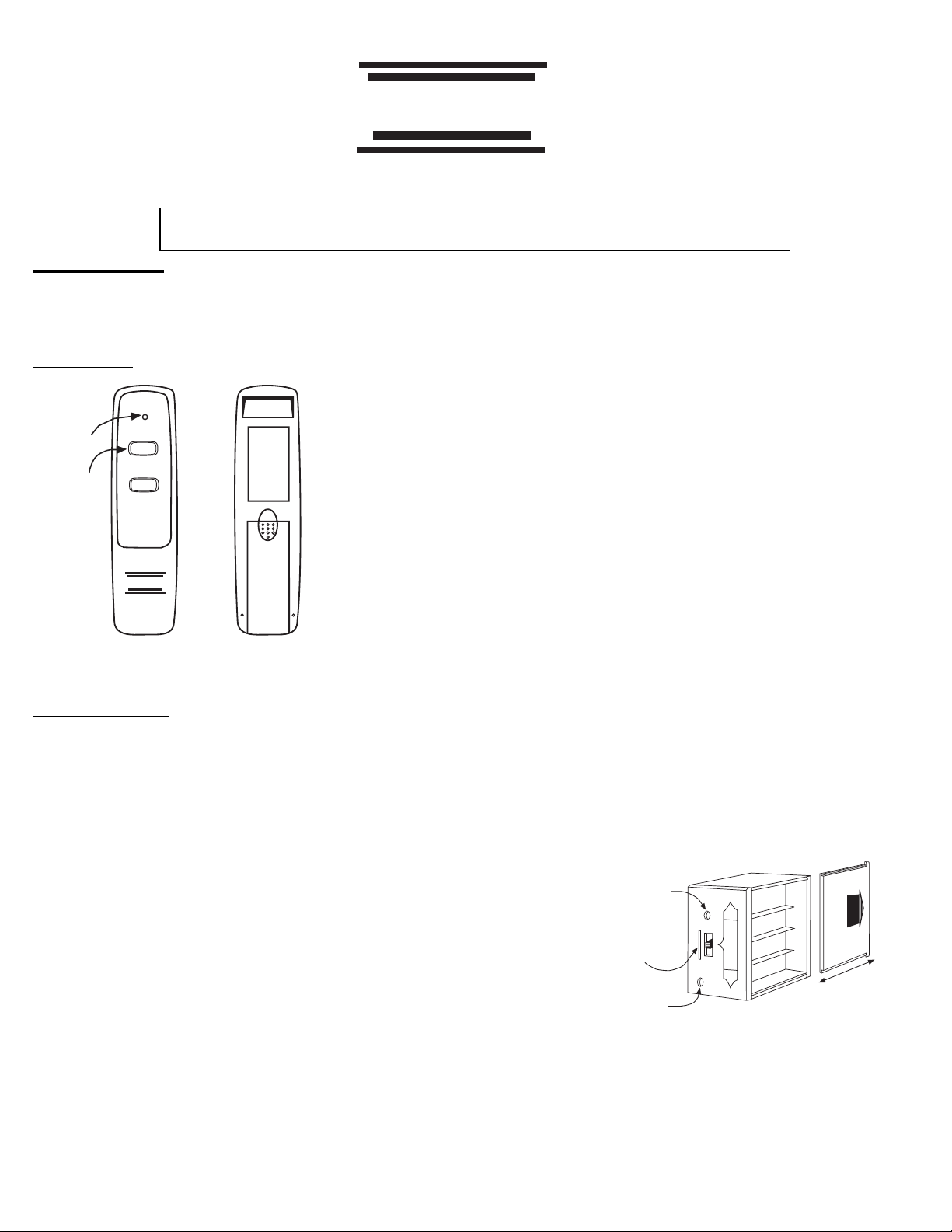
TRANSMITTER
WALL CLIP
SLOT
SIGNAL
LIGHT
ON/OFF
BUTTONS
REMOTE RECEIVER
The remote receiver operates on 4 AA-size 1.5V batteries. It is recommended that ALKALINE batteri es be used for longer battery life and
maximum microprocessor performance. IMPORTANT: New or fully charged batteries are essential for proper operation of the remote
receiver.
The remote receiver houses the microprocessor that responds to commands from the transmi tter to control system oper ation. The remote
receiver has a 3- position slide switch for sel ecting the MODE of operation: ON/REMOTE/OFF
• With the sli de swit ch in the ON position (toward the LEARN button), the system will
remain on until the sl ide switch is placed in the OFF or REMOTE position.
• With the slide switch in the REMOTE position (centered), the system will only operate
if the remote receiver receives commands from the transmitter.
• With the sli de switch in the OFF position (away from the LEARN butt on), the system
is off.
• It is suggested t hat the slide switch be placed in the off position if you will be
away from your home for an extended period of time. If the remote receiver is
mounted out of children’s reach, placing the slide switch in the OFF position
also functi ons as a safety “lock-out” by both turning the system off and
rendering the remote receiver inoperative.
ON
OFF
12V
BATTERY
ECS
FRONT BACK
COMPARTMENT
ECS
FRBC
ATTEMPT
The transmitt er oper ates on a 12V battery (included) made specifically for remot e
controls and electronic lighters. Install the 12V battery suppli ed wit h the unit into the
battery compart m ent.
It is recommended t hat AKALI N E batteries always be used for longer batt ery life and
maximum operational performance.
The transmitt er has ON and O FF funct ions that are activated by pressing either button
on the face of the transmit ter. When a button on the transmitter is pressed, a signal light
on the transmitter illuminates briefly to verify that a signal has been sent. Upon initial
use, there may be a delay of three seconds before the remote receiver wil l respond to
the transmit ter. This is part of the system’s design. If the signal light does not
illumi nate, check the position of the transmitter’s battery.
INSTALL OR OPERATE
Learning
button
Slide
Switch
ON
REMOTE
OFF
Frequency
adjusting
access hole
Requires 4-AA 1.5V
alkaline batteries
ON
LEARN
REMOTE
OFF
ADJ.
Remote Receiver
Battery cover slides on/off
REV 2/15/05Page 1 of 5 Part # 17808
Page 2
INSTALLATION INSTRUCTIONS
WARNING
This remote contr ol system must be installed exactly as outlined in these i nstructions. Read all instructions completely before
attempting installation. Follow instr uctions carefully during installation. Any modifications of the ECS remote control or any of its
components will void the warrant and may be pose a fire hazard.
Do not connect any gas valve or electronic module directly to 110-120VAC power. Consult gas appli ance manufacturer’s instructions
and wiring schemat ics for proper placement of all wir es. All electronic modules are to be wir ed to manufact urer’s specifications.
The following wiri ng diagrams are for illustration purpose only. Follow instru ctions from manufacturer of gas valve and/or electronic
module for corr ect wi ring procedures. Improper inst allation of electric components can cause damage to electronic module, gas valve
and remote receiver.
INSTALLATION
The remote receiver can be eit her wall-mounted in a standard plastic switch box or placed on or near the fireplace hearth. Preferably, the
remote receiver should be wall-mounted in a plastic switch box, as this will prot ect it s electronic components from both the heat produced by
the gas appliance and potential damage or abuse that can occur i f i t i s lef t exposed on t he hearth. PROTECTION FROM EXTREME HEAT IS
VERY IMPORTANT. Like any piece of electr onic equipment, the remote receiver should be kept away from temperatur es exceeding 130
0
F
inside the r eceiver case. Battery life is also significantly shortened if batt e ries are exposed to high temperat ures.
Make sure the remote recei ver switch is in the OFF position. It is r ecom m ended that 18 gauge solid or stranded wires (not included) be used
to make connections bet ween the terminal wiring block on the millivolt gas valve or electronic module and the wire terminals on the remote
receiver. For the best results, use 18 gauge solid or stranded wire, with no splices and measuring no longer than 20 ft.
WALL MOUNTING
Install 4 AA-size 1.5 ALKALINE batteries in the remote r eceiver. For best performance, remote receiver batteries should be factory fresh when
installed. Very little battery power is required to operate the remote recei ver, but the electronics are tuned to operate best when battery output
is greater than 5.3 volts. Four new AA batteries should provide an output voltage of 6.0 to 6.2 volts. Be sure batteries are installed with the
(+) and (-) ends facing t he correct direction.
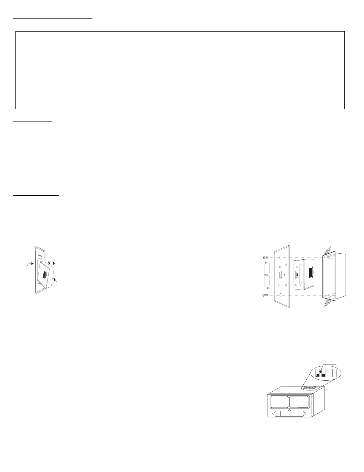
To attach Cover Plate to Receiver box
Position the receiver as shown in diagram to the left with lower
WALL
tab on cover plat e inser ted into groove of receiver (M ake sure
ADJ hole and LEARN hole on cover plate properly aligns with
ON
ON
LEARN
R
E
M
O
T
REMOTE
E
OFF
OFF
ADJ.
Cover Plate
(Rear View)
Remote Receiver
remote receiver ) Pull Receiver up and snap into top tab of cover
plate.
Position the cover plate so the word ON is facing up; then, install
Receiver
Slide
Button
LEARN
.
ADJ
the remote recei ver into the plastic switch box usi ng the t w o long
screws provided. Push the White Button over the receiver slide
switch only after making sure the remote receiver has LEARNED
the transmitter’s security code (see MATCHING SECURITY
CODES). NOTE: White Button covers both ADJ and Learn holes
when properly installed.
Cover Plate
Remote Receiver
Plastic Switch Box
NOTE: The remote receiver will only respond to the transmitter when the 3-position slide button on the remote receiver is in the
REMOTE position. If the syst em does not respond to the battery transmitter on initial use, see MATCHING
SECURITY CODES, and recheck battery positions in the remote receiver.
HEARTH MOUNT
Remote Receiver
MILLIVOLT
VALVE
The remote receiver can be placed on the fireplace hearth or under t he fi replace, behind the
control access panel . Position where the ambient tem perature inside the receiver case does
not exceed 130
0
F.
NOTE: Black Slide Button is used for Hearth Mount applications.
OFF
REMOTE
ON
REV 2/15/05Page 2 of 5 Part # 17808
Page 3
WIRING INSTRUCTIONS
A qualified elect rician or a gas technician who is familiar with the gas appliance and gas valves that wil l be operated by this remote should
install the r em ote control system. Incorrect wiring connections WILL cause damage to the gas valve or elect ronic module operating the gas
appliance and may also damage the remote receiver.
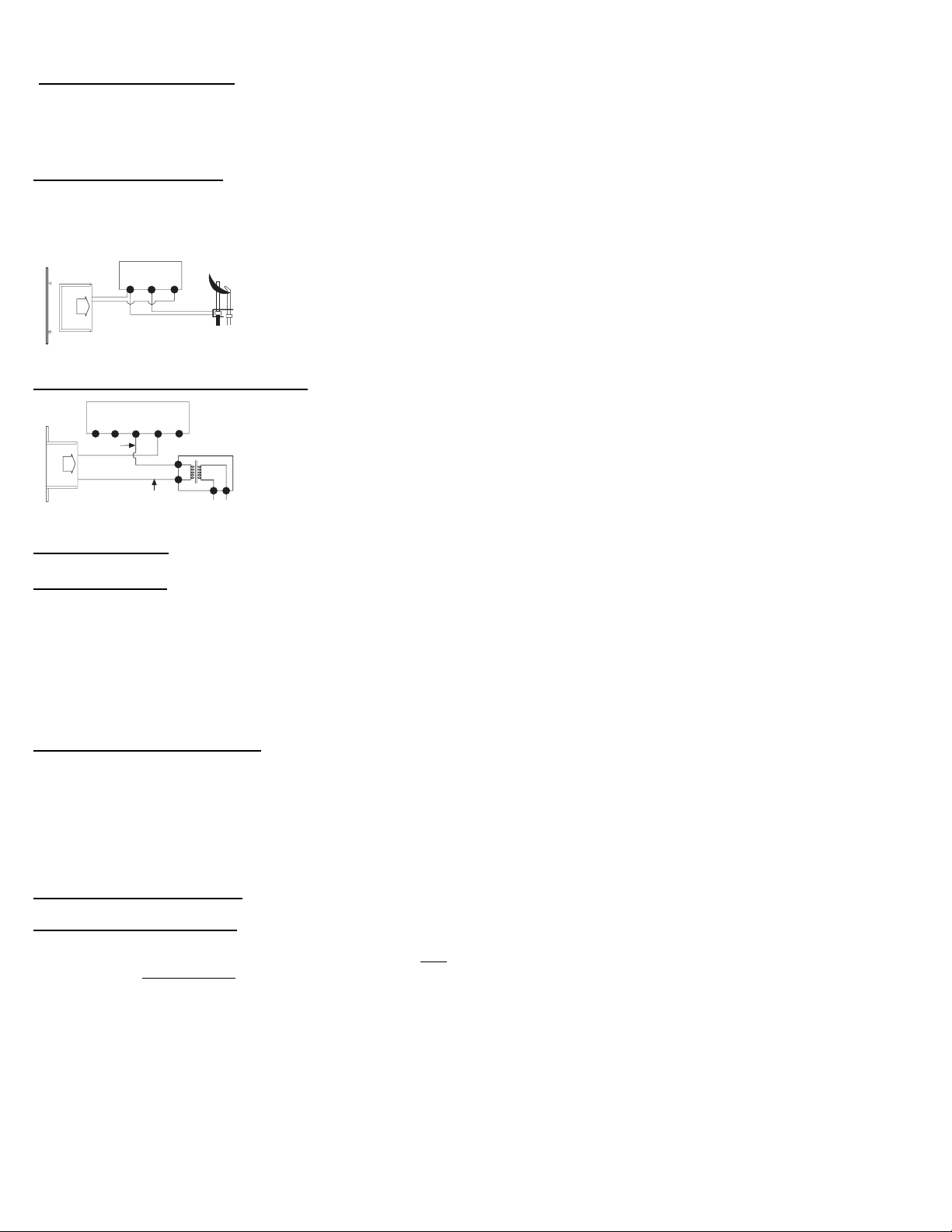
WIRING MILLIVOLT VALVES
The remote receiver is connected to the millivolt valve using the TH (thermostat) terminals on the terminal block on the millivolt gas valve.
Connect 18 gauge solid or stranded wires from the remote receiver to the gas valve.
TERMINAL BLOCK
ON MILLIVOLT
GAS VALVES
TH
TP
TP
Operation of the rem ote receiver is similar to that of a t hermostat in that both turn the gas valve on and off
TH
based on input signals. A thermostat’s input si gnals are different temper atur es. The remote receiver’s
input signals com e from the transmitter.
THERMOPILE/
PILOT LIGHT
REMOTE
RECEIVER
Connect each of the two wires l eading from the TH terminals on the millivolt gas valve to either of the two
wire terminals on t he remote receiver. Normally it does not matter which wires go to which terminal.
WIRING ELECTRONIC SPARK IGNITIONS
ELECTRONIC MODULE
neutral wire
REMOTE
RECEIVER
TR
24VAC
hot wire
TH
110/24VAC
Transformer
120VAC
The remote control recei ver can be connected, in series, to a 24VAC tr ansformer to the TR (transformer)
terminal on the ELECTRONIC MODULE. Connect the hot wire from the 24VAC transformer to either of
the wire terminal s on the remote receiver. Connect another wir e (not incl uded) between the other receiver
wire terminal and the TH (ther m ostat) terminal on the ELECTRONIC MODULE.
SYSTEM CHECK
MILLIVOLT VALVES
Light your gas appliance following the lighti ng instructions that came with the appliance. Confirm that the pilot f lame is on; it must be in
operation f or t he main gas valve to operate.
• Slide the 3-position button on the remote receiver t o the ON posit ion. The main gas flame (i.e., the fire) should ignite.
• Slide the button t o OFF. The flame shoul d extinguish (the pilot flame will remain on).
• Slide the button to REMOTE (the center position), then pr ess the ON button on the transmitter to change the syst em to ON. The main gas
flame should i gnit e.
ELECTRONIC IGNITION SYSTEMS
• Slide the 3-position button on the remote receiver t o the ON position. The spark electr ode should begin sparking to ignite the pilot (the
pilot may ignite after only one spark). After the pilot flame is lit, the main gas valve should open and the main gas flame should ignite.
• Slide the button t o OFF. The main gas fl am e and pilot fl ame should BOTH extinguish.
• Slide the button to REMOTE (the center position), then pr ess the ON button on the transmitter to change the syst em to ON. The spark
electrode should begin sparking to ignite the pilot. After the pilot is lit, the main gas valve should open and the main gas flame should
ignite.
GENERAL INFORMATION
MATCHING SECURITY CODES
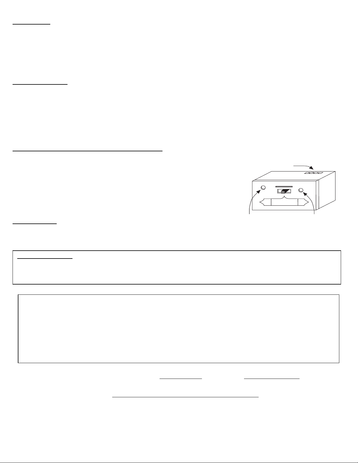
Each transmitt er can use one of 255 unique security codes. It may
of the transmitter upon initial use
, if batteries are replaced, or if a replacement transmit ter is purchased from your dealer or the f actory. When
matching securi ty codes, be sure slide button on the recei ver is in the REMOTE position; the code will NOT “LEARN” if the slide switch is in the
ON or OFF position. Program the remot e recei ver to LEARN a new security code by pushing in the LEARN button on the top of the remote
receiver and t hen pressing the MODE button on the transmitter. A change in t he beeping pattern, at the receiver, indi cates the transmitter ’s
code has been programmed into the receiver. When an existing receiver is matched to a new transmitter , the new security code will override
the old one.
The microprocessor that controls the security code matching procedure is cont rolled by a timing function. If you are unsuccessful in matching
the securit y code on the first attempt, wait 1-2 minutes before trying again – this delay al lows the microprocessor to reset its timer circuitry –
and try up to two or three more ti m es.
be necessary to program the rem ote r eceiver to LEARN the security code
REV 2/15/05Page 3 of 5 Part # 17808
Page 4
BATTERY LIFE
Life expectancy of the alkaline batteries in the transmitter should be at least 12 months. Check and replace all batteries annually. When the
transmitt er no l onger operates the remote receiver from a distance it did previously (i.e., the transmitt er’s range has decreased) or the remote
receiver doe not funct ion at all, the batteries shoul d be checked. It is important that the remote receiver batteries ar e fully charged and
provides continuous output voltage of a least 5.3 volts. The length of the wire between the remote recei ver and gas valve directly affects the
operating per formance of the remote system. The longer the wir e, the more battery power is required to deli ver signals between the remote
receiver and t he gas valve. Recommended length is no longer than 20 feet. The transmitter should operate with as li tt le as 5.0 volts battery
power.
TROUBLE SHOOTING
If you encounter probl em s wit h your fireplace system, the pr oblem may be with the fireplace itself or it could be with the ECS remote. Review
the fireplace manufacturer’s operati on m anual to make sure all connections ar e properly made. Then check the operation of the ECS remote
in the following manner:
• Make sure the batter ies are correctly installed in the RECEIVER. One reversed battery will keep receiver from operating properly.
• Check battery i n Transmitter to make sure contacts are touching (+) and (-) ends of battery. Bend metal cont acts in for tighter fit.
• Be sure RECEIVER and Transmitter ar e wit hin 20’-25’ operating range.
• Keep RECEIVER from temperatures exceedi ng 130
0
F. Battery life shortened when ambient temperatures are above 1300 F.
• If RECEIVER is installed i n ti ghtl y enclosed metal surround, the operating distance will be shortened.
RECEIVER ADJUSTMENT – RECOMMENDED ADJUSTMENT
NOTE: The slide button, Whit e or Black, covers the ADJ access hole when installed.
A. To adjust at the receiver, use a small slotted screwdri ver. Turn the adjustment screw
Remote Receiver
Wire terminals
counter-cl ockwise about 5 degrees or a maximum of 1/8 turn. This should correct the
distance probl em.
B. If that does not correct the problem, return adjust m ent screw to original positi on and
ADJ.
LEARN
then turn adj ustment screw clockwise.
This adjustment is like tuning your radio. If you keep tur ning the adjustment screw, in either
direction, you will go past the proper setti ng (t uning).
OFF
REMOTE
ON
SPECIFICATIONS
Frequency adjusting
access hole
Learning
button
BATTERIES: Transmitter 12V (A23)
Remote Receiver 6V –4ea. AA 1.5 Alkaline FCC ID No.’s: transmitter –K9L1002TX; receiver – K9L3001RX
Operating Fr equency: 303.875MHZ Canadian ISC ID No.’s: transmitter –2439 102 728; receiver – 2439 102 728A
FCC REQUIREMENTS
NOTE: THE MANUFACTURER IS NOT RESPONSIBLE FOR ANY RADIO OR TV INTERFERENCE CAUSED BY UNAUTHORIZED
MODIFICATIONS TO THIS EQUIPMENT. SUCH MODIFICATIONS COULD VOID THE USER’S AUTHORITY TO OPERATE THE
EQUIPMENT.
This REMOTE CONTROL SYSTEM is warranted for 12 months from the date of purchase or installation to the original
purchaser to be free from defects in materials and workmanship. Damage to the SYSTEM caused by accident, misuse,
abuse, or installation error whether performed by a contractor, service company, or owner, is not covered by this
warranty. Seller will not be responsible for labor charges and/or damage incurred in installation, repair, replacement or
for incidental or consequential damages. Batteries and any damage caused by them are not covered by this warranty.
Some states, provinces, and nations do not allow exclusion or limitations of incidental or consequential damages, so the
above limitations or exclusions may not apply. This warranty gives you specific legal rights. You may have other rights
that vary by state, province or nation.
Limited Warranty
FOR TECHNICAL U.S. INQUIRIES
CANADIAN INQUIRIES
SERVICE, CALL: 888/672-8929 or 260/459-1703 877-472-3923
Website: skytechsystem.com
MANUFACTURED EXCLUSIVELY BY SKYTECH II, INC
REV 2/15/05Page 4 of 5 Part # 17808
Page 5

REMOTE ON/OFF RECEIVER
INSTALLATION INSTRUCTIONS
16660
EFFECTIVE DATE JUNE 2004
INSTRUCTIONS MUST BE LEFT WITH THE OWNER FOR FUTURE REFERENCE AFTER INSTALLATION.
Remote ON/OFF Receiver - Cast Ir on Seri es
Use the following steps to attach the remote receiver to the cast iron stoves:
1. Attach, from left to right, the slide-on cover plate onto the remote receiver. ON will be to the top and OFF will be to the bottom on the slide-
on cover plate.
2. Push the receiver slide button onto the receiver slide swit ch. Reverse installation of the slide button if it is off center.
3. Attach velcro loop on the left side of the valve cover support.
4. Attach velcro hook onto remote receiver. The word TOP on the remote receiver should be to the top when installed onto valve cover
support.
5. Attach velcro hook on remote receiver onto velcro loop on valve cover support.
Remote ON/OFF Receiver - Direct Vent Fir eplaces and Vent-Free Fireplaces
Use the following steps to place the remote receiver in the bottom of the inner casing assembly, adj acent to the gas valve.
1. The remote receiver can not be placed behind the gas valve.
2. When facing the appliance, the remote receiver must be placed to the right of the gas valve.
Remote ON/OFF Receiver - Vent-Free Log Sets (Millivolt System)
Use the following steps to place the remote receiver adjacent to the gas valve.
1. The remote receiver can not be placed behind the gas valve and burner assembly.
2. When facing the appliance, the remote receiver can be placed to the right of the gas valve and burner assembly or under burner pan left of
gas valve.
Remote ON/OFF Receiver - DV-210 and DV-215
Attention: Do not install remote receiver inside furnace.
Use the following steps to attach remote receiver.
1. Attach remote receiver at bott om of either side on outer casing.
2. If furnace is installed high enough above floor, attach r emote recei ver on the underside of furnace.
Remote ON/OFF Receiver - DV-25 and DV-35
Attention: Do not install remote receiver inside furnace.
Use the following st ep to att ach remote receiver.
1. Attach remote receiver to the under side of the furnace, adjacent to the right of piezo ignitor.
Remote ON/OFF Receiver - DVC-35, DV-55, FAW-40 and FAW-55
Use the following st ep to att ach remote receiver.
1. Attach remote receiver in the i nterior, bottom of furnace, adj acent t o gas valve.
Remote ON/OFF Receiver - GWT-25, GWT- 35 and GWT- 50
Use the following st ep to att ach remote receiver.
1. Attach remote receiver to wall sill or floor plate.
Remote ON/OFF Receiver - DV-20E, DV-40E and DV-55E
Use the following st ep to att ach remote receiver.
1. Attach remote receiver in the i nterior of the furnace, adjacent to t he right of pressure switch.
Attention: Velcro loop and hook are not necessary for al l i nstallations.
REV 2/15/05Page 5 of 5 Part # 17808
 Loading...