


EA2160 |
EA2220 |
EA480 |
2-/4-/5-CHANNEL AMPLIFIERS |
Installation & Operating Manual |
Einbau- & Bedienungsanleitung |

CONTENTS
1. |
DESIGN FEATURES |
5 |
2. |
CONNECTIONS & CONTROLS |
6-11 |
2.1 |
FRONT & REAR PANEL CONNECTION & CONTROLS EA2160/EA2220 |
6-7 |
2.2 |
FRONT & REAR PANEL CONNECTIONS & CONTROLS EA480 |
8-9 |
2.3 |
FRONT & REAR PANEL CONNECTION & CONTROLS EA450-300 |
10-12 |
2.4 |
SPEAKER IMPEDANCE & POWER WIRE INFO |
13 |
3. |
AMPLIFIER MOUNTING |
13 |
4. |
WIRE ROUTING |
14 |
4.1 |
MAIN POWER WIRES |
14 |
4.1 |
RCA & REMOTE WIRES |
14 |
4.3 |
LOUDSPEAKER WIRES |
14 |
5. |
CROSSOVER ADJUSTMENTS |
15 |
5.1 |
SELECTING THE OPERATION MODE |
15 |
5.2 |
HIGHPASS CROSSOVER FREQUENCY ADJUSTMENT |
15 |
5.3 |
LOWPASS CROSSOVER FREQUENCY ADJUSTMENT |
15 |
5.4 |
SUBSONIC HIGHPASS CROSSOVER ADJUSTMENT |
16 |
5.5 |
INPUT LEVEL ADJUSTMENT |
16 |
6. |
TECHNICAL SPECIFICATIONS |
32-33 |
7. |
EMPHASER LIMITED WARRANTY |
34 |
7.1 |
EMPHASER WARRANTY LIMITATIONS |
34 |
8. |
WARRANTY CARD |
35 |

INHALT
1. |
TECHNISCHER AUFBAU / MERKMALE |
17 |
2. |
ANSCHLÜSSE & BEDIENUNGSELEMENTE |
18-23 |
2.1. |
EINGÄNGE & FUNKTIONEN AM FRONT & REAR PANEL EA2160/EA2220 |
20-21 |
2.2 |
EINGÄNGE & FUNKTIONEN AM FRONT & REAR PANEL EA2160/EA2220 |
22-23 |
2.3 |
EINGÄNGE & FUNKTIONEN AM FRONT & REAR PANEL EA2160/EA2220 |
24-26 |
2.4 |
LAUTSPRECHER-IMPEDANZ & POWERKABEL INFO |
27 |
3. |
MONTAGE DES VERSTÄRKERS |
28 |
4. |
VERKABELUNG / ELEKTRISCHER ANSCHLUSS |
28 |
4.1 |
HAUPT-STROMKABEL |
29 |
4.2 |
CINCH- & REMOTE KABEL |
29 |
4.3 |
LAUTSPRECHERKABEL |
29 |
5. |
EINSTELLUNG DER FREQUENZWEICHE |
29 |
5.1 |
WAHL DES OPERATIONS-MODUS |
29 |
5.2 |
HOCHPASS TRENNFREQUENZ EINSTELLUNG |
30 |
5.3 |
TIEFPASS TRENNFREQUENZ EINSTELLUNG |
30 |
5.4 |
SUBSONIC HOCHPASS TRENNFREQUENZ EINSTELLUNG |
30 |
5.5 |
ANPASSUNG DER EINGANGSEMPFINDLICHKEIT |
31 |
6. |
TECHNISCHE SPEZIFIKATIONEN |
32-33 |
7. |
EMPHASER GARANTIE-BESTIMMUNGEN |
34 |
7.1 |
EMPHASER GARANTIE-EINSCHRÄNKUNGEN |
34 |
8. |
GARANTIEKARTE |
35 |

Congratulations!
And thank you for choosing this EMPHASER car audio amplifier!
To maximize the performance of this amplifier and your car audio system install, we recommend that you acquaint yourself thoroughly with all capabilities and features of the EMPHASER amplifier model you have chosen. Please read this manual carefully, before attempting the installation of this amplifier. Please retain this manual and your purchasing / installation receipts for future reference.
IMPORTANT NOTICE:
In case you are installing your EMPHASER amplifier by yourself, you should have your installation checked and approved by an authorized professional EMPHASER dealer/installer, in order to qualify for full warranty protection and also, to reach maximum power-output and audio performance possible with your individual car audio system.

1.DESIGN FEATURES
■CAR AUDIO Amplifier: This EMPHASER amplifier allows the crossover controlled amplification of satellite speaker systems, kickwoofer or subwoofer systems
■Dash-Mount Remote Lowpass Level Control: A compact „Lowpass-Level“ remote control unit can be mounted close to the drivers seat. This control device allows the convenient level adjustment of the bass volume (not applicable for EA480)
■FULL-MOSFET CIRCUITRY: This EMPHASER amplifier line features a full MOS-FET circuitry layout, implementing MOS-FET’s for power supply and output stages, to guarantee excellent sonic performance and very high power output
■Load Stability: This EMPHASER amplifier line up features models that work stable and reliable into very low impedance loads. Due to the high damping factor, every model of this amplifier line will guaranteed to have full control over the connected speaker system(s)
■Integrated Electronic CROSSOVER: The internal crossover section features independently selectable highpass or bandpass filtering, as well as fulllrange loop through. All x-overs feature crossover slope rates of 12/24 dB/octave
■Uncompromising Design AND CONSTRUCTION: Only best electrical and electronic components have been used for the assembly of this amplifier line. Such as double-sided glass-fiber epoxy circuit boards equipped with high current TR output devices.
■Advanced Protection Circuitry: The protection circuitry safe-guards the amplifier from short-circuits at the speaker outputs, DC offset voltage at the outputs and overheating of power electronics
■Status and Protection LED’s: A green and a red LED located at the side panel enable you to monitor the operating status of your EMPHASER amp
■Adjustable Input Sensitivity: Each RCA line-input pair accepts input voltages from 300mV to 7V, providing a good match to the line-output levels of almost any head-unit on the market

2. CONNECTIONS & CONTROLS
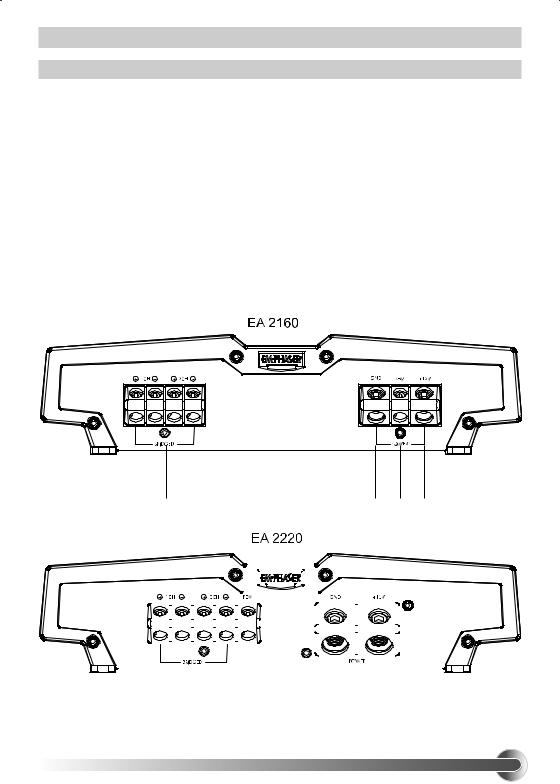
2.1 REAR PANEL EA2160/EA2220
9“OUTPUT TERMINALS”
Loudspeaker output terminal to connect the loudspeakers.
10“GND” POWER INPUT TERMINAL
Moulded direct power input terminals to connect the amplifier to the negative or ground wire of the vehicle
11“REMOTE” INPUT TERMINAL
Terminal to connect the amplifier to the automatic (remote) turn-on / turn-off lead of the head unit
12“+12V” POWER INPUT TERMINAL
Moulded direct power input terminals to connect the amplifier to the positive +12V power wire connected to the car battery
|
|
9 |
|
|
|
|
|
|
|
|
|
|
|
|
|
|
|
|
bl bm bn |
||||||
|
|
|
|
|
|
|
|
|
|
|
|
|
|
|
|
|
|
|
|
|
|
|
|
|
|
|
|
|
|
|
|
|
|
|
|
|
|
|
|
|
|
|
|
|
|
|
|
|
|
|
|
|
|
|
|
|
|
|
|
|
|
|
|
|
|
|
|
|
|
|
|
|
|
|
|
|
|
|
|
|
|
|
|
|
|
|
|
|
|
|
|
|
|
|
|
|
|
|
|
|
|
|
|
|
|
|
|
|
|
|
|
|
|
|
|
|
|
|
|
|
|
|
|
|
|
|
|
|
|
|
|
|
|
|
|
|
|
|
|
|
|
|
|
|
|
|
|
|
|
|
|
|
|
|
|
|
|
|
|
|
|
|
|
|
|
|
|
|
|
|
|
|
|
|
|
|
|
|
|
|
|
|
|
|
|
|
|
|
|
|
|
|
|
|
|
|
|
|
|
|
|
|
|
|
|
|
|
|
|
|
|
|
|
|
|
|
|
|
|
|
|
|
|
|
|
|
|
|
|
|
|
|
|
|
|
|
|
|
|
|
|
|
|
|
|
|
|
|
|
|
|
|
|
|
|
|
|
|
|
|
|
|
|
|
|
|
|
|
|
|
|
|
|
|
|
|
|
|
|
|
|
|
|
|
|
|
|
|
|
|
|
|
|
|
|
|
|
|
|
|
|
|
|
|
|
|
|
|
|
|
|
|
|
|
|
|
|
|
|
|
|
|
|
|
|
|
|
|
|
|
|
|
|
|
|
|
|
|
|
|
|
|
|
|
|
|
|
|
|
|
|
|
|
|
|
|
|
|
|
|
|
|
|
|
|
|
|
|
|
|
|
|
|
|
|
|
|
|
|
|
|
|
|
|
|
|
|
|
|
|
|
|
|
|
|
|
|
|
|
|
|
|
|
|
|
|
|
|
|
|
|
|
|
|
|
|
|
|
|
|
|
|
|
|
|
|
|
|
|
|
|
|
|
|
|
|
|
|
|
|
|
|
|
|
|
|
|
|
|
|
|
|
|
|
|
|
|
|
|
|
|
|
|
|
|
|
|
|
|
|
|
|
|
|
|
|
|
|
|
|
|
|
|
|
|
|
|
|
|
|
|
|
|
|
|
|
|
|
|
|
|
|
|
|
|
|
|
|
|
|
|
|
|
|
|
|
|
|
|
|
|
|
|
|
|
|
|
|
|
|
|
|
|
|
|
|
|
|
|
|
|
|
|
|
|
|
|
|
|
|
|
|
|
|
|
|
|
|
|
|
|
|
|
|
|
|
|
|
|
|
|
9 |
bm |
bl bn |

2. CONNECTIONS & CONTROLS
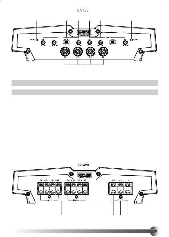
2.2FRONT PANEL EA480
1POWER LED
Green „operation“ LED, signaling correct operation of the amplifier.
2INPUT GAIN CONTROL 1/2-CH
Input level control for 1/2-CH amplifier section - allowing to match the output voltage of the head-unit‘s RCA line-outs to the amplifier input section.
3HIGH PASS FREQUENCY CONTROL 1/2-CH
Control for the frequency adjustment of the 12dB/oct. high-pass filtering of the speakers connected to 1/2-CH output terminals.
4OPERATION MODE SWITCH 1/2-CH
Switch to select the operation mode of the crossover filter driving 1/2-CH section of the amplifier.
5LOW PASS FREQUENCY CONTROL 1/2-CH
Control for the frequency adjustment of the 24dB/oct. low-pass filtering of the speakers connected to 1/2-CH output terminals.
6INPUT GAIN CONTROL 3/4-CH
Input level control for 3/4-CH amplifier section - allowing to match the output voltage of the head-unit‘s RCA line-outs to the amplifier input section.
7HIGH PASS FREQUENCY CONTROL 3/4-CH
Control for the frequency adjustment of the 12dB/oct. high-pass filtering of the speakers connected to 3/4-CH output terminals.
8OPERATION MODE SWITCH 3/4-CH
Switch to select the operation mode of the active crossover driving 3/4-CH section of the amplifier.
9LOW PASS FREQUENCY CONTROL 3/4-CH
Control for the frequency adjustment of the 24dB/oct. low-pass filtering of the speakers connected to 3/4-CH output terminals.
10PROTECTION LED
Red „protection“ LED, signaling faulty speaker connections or general malfunction of the amplifier.
11RCA INPUTS 1/2-CH 3/4-CH
Low-level stereo RCA signal input for connection with head-unit.
1 2 3 4 5 6 7 8 9 bl
bm
2. CONNECTIONS & CONTROLS
2.2 REAR PANEL EA480
12SPEAKER OUTPUT TERMINALS 1/2-CH and 3/4-CH
Output terminals to connect the speakers in stereo or bridged mode to the amplifier.
13„GND“ POWER INPUT TERMINAL
Terminal to connect the amplifier to the negative or ground pole of the car battery.
14„REM“ REMOTE INPUT TERMINAL
Terminal to connect the amplifier to the automatic (remote) turn-on / turn-off lead of the head unit.
15„+12 V“ POWER INPUT TERMINAL
Terminal to connect the amplifier to the positive +12V pole of the car battery.
bn |
bo bp bq |

2. CONNECTIONS & CONTROLS
2.3FRONT PANEL EA450-300
1RCA INPUTS 1/2-CH
Low-level stereo RCA signal input for connection with head-unit.
2RCA INPUTS 3/4-CH
Low-level stereo RCA signal input for connection with head-unit.
3STEREO RCA INPUT 5-CH
Low-level stereo RCA signal input for connection with head-unit.
4POWER LED
Green „operation“ LED, signaling correct operation of the amplifier.
5INPUT GAIN CONTROL 1/2-CH
Input level control for 1/2-CH amplifier section - allowing to match the output voltage of the head-unit‘s RCA line-outs to the amplifier input section.
6HIGH PASS FREQUENCY CONTROL 1/2-CH
Control for the frequency adjustment of the 12dB/oct. high-pass filtering of the speakers connected to 1/2-CH output terminals.
7OPERATION MODE SWITCH 1/2-CH
Switch to select the operation mode of the active crossover driving 1/2-CH section of the amplifier.
8INPUT GAIN CONTROL 3/4-CH
Input level control for 3/4-CH amplifier section - allowing to match the output voltage of the head-unit‘s RCA line-outs to the amplifier input section.
9HIGH PASS FREQUENCY CONTROL 3/4-CH
Control for the frequency adjustment of the 12dB/oct. high-pass filtering of the speakers connected to 3/4-CH output terminals.
10OPERATION MODE SWITCH 3/4-CH
Switch to select the operation mode of the active crossover driving 3/4-CH section of the amplifier.
11LOW PASS FREQUENCY CONTROL 3/4-CH
Control for the frequency adjustment of the 24dB/oct. low-pass filtering of the speakers connected to 3/4-CH output terminals.
12INPUT GAIN CONTROL 5-CH
Input level control for 5-CH amplifier section - allowing to match the output voltage of the head-unit‘s RCA line-outs to the amplifier input section.
10
 Loading...