


EMP MODEL 200/250
OPERATION MANUAL
CONTENTS…………………………………………………………………………page 1 INSTALLATION DATA………………………………………………………………... 2 MODEL 200/250 CONTROLLER……………………………………………………… 3 FS/RC SCANNER OPERATION.……………………………………………………… 4 SELECTOR SWITCH…………...……………………………………………………… 5 TRANSMISSION………………..……………………………………………………… 6 REGISTRATION MARKS……...……………………………………………………… 7 INTERNAL VIEW OF MODEL 200/250………………………………………………. 8 MODEL 200/250 INTERNAL COMPONENTS…………..…………………………… 9 MODEL 200/250 SPB SETTINGS & ALARM CONTROL……………………….. 10-11 MODEL 200/250 INTERNAL SET UP, MOTOR TYPE & LENGTH TIMING…...…. 12 MOTOR WIRING………………………….……………………………………………. 13 MOTOR STARTER WIRING……………………………………………………….….. 14 SYSTEM CHECKOUT………….………………………………………………………. 15 SET-UP & OPERATING PROCEDURE…………….……………………………... 16-17 SET-UP & OPERATING PROCEDURE ILLUSTRATIONS…………………………. 18 TROUBLE SHOOTNG GUIDE……………………………………………………. 1921 CIRCUIT DESCRIPTION………………………………………………………………. 22 MODEL 200/250 INTERNAL BLOCK SCHEMATIC………………………………… 23 FRONT PANEL PARTS LIST…..……………………………………………………… 24 SELECTOR SWITCH PARTS….……………………………………………………… 25 RECOMMENDED SPARE PARTS LIST AND WARRANTY…………………….…. 26
(1)
INSTALLATION
CONTROLLER
The Model 200 or 250 Controller requires;
(1)A clean 120VAC 50-60HZ +/- 8% With;
(a)Peak Power Requirement 960 VA - 1 Second Motor Inrush
(b)Peak Line Current 8 AMP
(c)Steady State Line Current 2 AMP (with Motor Running)
(2)The Controller must be mounted to minimize vibration. It should also be conveniently placed for operator to view all indicator LED’s for the Front Panel Adjustments.
(3)All cables to the Scanner, Motors and Selector Switch should not be run with any cables from heaters, static eliminators, Main Drive Motors or power cables.
SCANNER
The Scanner must be firmly mounted to minimize any machine vibration. For best registration results, the Scanner should be positioned as close to the knife as possible. See Page 4 for additional information.
SELECTOR SWITCH
The Selector Switch must be driven in an integral relationship. (1:1, 2:1, 3:1, etc.) with the knife at a speed not exceeding the 500 RPM. Since there are adjustments made to the Selector Switch, the operator must have access to it.
TRANSMISSION
The DDT Transmission must be firmly secured to a flat rigid foundation. The Transmission can be secured with bolts through the slotted mounting holes on the Mount Plate. The Mount Plate must rest firmly on the foundation before bolting down. Align shafts accurately. When using direct coupling connection, a flexible coupling is recommended. If gearing or timing belts are used, the gears or pulleys should be mounted on the main shafts as close to the housing as possible. This will minimize overhung loads. GUARDS must be used since external moving parts pose a danger.
LUBRICATION
All EMP Transmissions are shipped without oil. Before starting, add the specified quantity of Mobil Gear # 629 Oil. If this oil in not available, the substitute must be a 4EP Grade Oil. After the first 100 hours of operation and every 2000 hours thereafter, change the oil.
(2)
MODEL 200/250 CONTROLLER
The Front Panel contains the indicators and adjustment controls necessary for proper operation. The function of each of the front panel part is as follows.
Retard LED |
This red LED lights each time the Selector Switch vane passes |
|
trough it’s retard area. |
Advanced LED |
This green LED lights each time the Selector Switch vane passes |
|
through the advance area. |
Retard Timing Knob |
Used to control the timing of the Correction Motor in the retard |
|
mode. |
Advanced Timing Knob |
Used to control the timing of the Correction Motor in the advance |
|
mode. |
Retard Indicator |
This switch will light each time a retard correction takes place. It is |
and Jog Switch |
also used to manually jog the printed web into position. |
Advanced Indicator |
This switch will light each time an advance correction takes place. |
and Jog Switch |
It is also used to manually jog the printed web into position. |
Scanner LED |
This amber LED will flash when any printed matter is detected by |
|
the scanner. |
Sensitivity Knob |
This adjustment varies the sensitivity of the scanner. The higher |
|
the setting, the more sensitive the scanner is to contrasting colors. |
Correction Motor |
This switch when lit, indicates that the Correction Motor is in its |
ON/OFF |
automatic mode. |
Length Motor |
This switch when lit, indicates that the Length Motor is in its |
ON/OFF |
automatic mode. This switch is found only on the Model 250 Dual |
|
Motor Controllers. |
Alarm LED |
This red LED flashes once an out of tolerance alarm condition |
|
exists. |
Alarm On-Off |
This switch when on indicated that the out of tolerance system is |
|
activated. |
(3)
FS or RC SCANNER
Both the RC and FS Scanners detect all colors by sensing changes in contrast. The actual detection by the Scanner takes place at either edge of the register mark. Provision is made on the Controller for selecting either a light increase or decrease at the mark’s edge. Using an example of a black mark against a white background, the scanner is stabilized by the white background. Upon detecting the leading edge of the black mark, a signal is generated when using the Dark Mark mode. If the Light Mark mode was used, the signal would be generated when leaving the register mark. Either edge of the mark may be used depending upon the relative color and contrast between the mark and it’s background.
When the web is transparent, a bracket mounted under the web is required so the scanner light can be reflected back to the scanner. The bracket must provide the contrast normally provided by the web.
A foil adaptor is available for use with webs that are highly reflective (foil, etc.). The adaptor angles the Scanner for optimum detection under these conditions.
To maintain the Scanner’s performance, an occasional wipe of the lens’ surface with a Q-Tip and alcohol is recommended.
1.FS Focalite Scanners:
A focusing LED is provided with this scanner, which helps the operator bring the scanner into sharper focus. To focus the scanner correctly, perform the following steps:
1.Position the scanner about 1 inch from the web and observe the focusing L.E.D.
2.Move the scanner closer to the web slowly. The focusing L.E.D. Will begin to glow with increasing intensity.
3.The L.E.D. will reach a maximum intensity, movement of the scanner either towards or away from the web causes the LED to lose intensity.
4.The scanner is now correctly focused. Lock it in this position.
2.RC Scanners:
Position the scanner approximately 3/8 to ½ of an inch from the web to insure correct focus. When properly focused, the scanner light will create a 1/8” round image on the web.
(4)
SELECTOR SWITCH
The Selector Switch is used to provide a signal to the Controller, indicating the position of the knife. The Selector Switch is normally geared 1:1 to the knife. When the rotary knife has 2 or 3 blades, the switch should be geared 2:1 or 3:1.
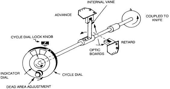
The Selector Switch is housed in a rugged two piece casting which protects the electronics from the industrial environment and provides a secure mounting. Inside the Selector Switch, are the ADVANCE and RETARD OPTIC BOARD ASSEMBLIES. The position of each Optic Board Assembly represents the Advance and Retard flags located on the Cycle Dial of the Selector Switch. When the Advance or Retard Flag is repositioned, the corresponding Optic Board is also adjusted. The area between the Advance and Retard flags is known as the DEAD AREA. This represents the area where the Internal Vane is not blocking either the Advance or Retard Optic, therefore no corrections are made.
During the operation of the registration system, the Register Mark is detected by the Scanner as the arrow on the Selectors Switch’s indicator dial reaches either the Retard Optic Board active area, the dead area or the Advance Optic Board active area. Should the Register Mark be sensed while the indicator arrow is in either the advance or retard active area, a correction will take place. This active area is determined by the width of the vane located on the Selector Switch shaft. For more information regarding the active area refer to page 7.
In addition the Selector Switch has a print adjust feature which allows the web position to be adjusted in relationship to the knife. This is achieved by adjusting the Cycle Dial of the Selector Switch.
INTERNAL VIEW OF SELECTOR SWITCH
(5)
TRANSMISSION
The fourth component of the EMP Register System is the Differential Transmission. Based on your application, EMP will recommend the unit that will best serve your needs.
The choices are;
1- DDT-MVC Transmission-Uses both a correction and length motor
2- DDT Transmission-Uses only a correction motor
3- T-2 Transmission-Uses only a correction motor
4- ILDT Transmission-Uses only a correction motor
The selection of the Transmission will also affect your choice of a Controller. The Model 250 Dual Motor Register System is required for the DDT-MVC Transmission and if an existing PIV is being motorized. All other transmissions listed operate with the Model 200 Controller since all units are single motor controllers.
For all preprinted registration applications, EMP recommends the DDT-MVC or DDT Transmission. The DDT Transmission’s ability to correct both length errors as well as random register errors provides the most accurate registration. The DDT Transmission maintains the registration by regulation the speed of the machine’s Draw Rollers. The Correction Motor will receive signals from the Controller. The correction will momentary adjust the Draw Roller Speed, which will advance or retard the amount of preprinted web delivered to the knife. The Length Motor used on the DDT-MVC will make adjustments to the Variator. These adjustments correct the constant length error portion or register error.
For additional information, please refer to the operating manual of the transmission used in your application.
(6)
REGISTRATION MARKS
The Registration Mark is the reference that tells the Controller the printed web’s exact position. It is important that the Registration Mark have the following characteristics:
1 - Color - Since the Scanner “sees” the mark by sensing the change in colors, contrast is the key. High contrast (Dark color on light or vice versa) provides the best signal ratio and control reliability. Plan early to use bright, well defined, contrasting colors in your operation.
2 - Size - EMP recommends the mark to be a minimum of 3/8” in length and 1/8” wide. This size is recommended because the 3/8” length allows for slight side to side web drift while still remaining in the path of the Scanner. The width of 1/8” provides the scanner enough time to sense the contrast.
3 - Minimum Clear Space - To maintain proper registration, only the Register Mark can give the signal to the controller. To help the system recognize only the Register Mark, a clear unprinted area before and after the Registration Mark is required. The size of this clear area is determined by the size of the internal vane of the Selector Switch.
(See chart below for vane sizes).
For our example we will assume the following;
1)Standard HSS9 Switch with 30 degree active area.
2)The repeat length of the web is 12 inches.
3)The Selector Switch and Knife rotate in a 1:1 ratio.
Under these circumstances, we require a 1 inch clear area before and after the Registration Mark.
(30 degrees / 360degrees) X 12” Repeat Length = 1 inch
Should you have any questions regarding the Registration Mark, please send sample to EMP for testing.
Selector Switch Part No. |
Active Area |
Description |
||
CCW |
or |
CW |
|
|
HSS9 |
or |
HSS91 |
30 degrees |
Standard |
HSS94 |
or |
HSS914 |
18 degrees |
Narrow Active Area |
SSB9 |
or |
SSB91 |
30 degrees |
Worm wheel adjustment |
SSB94 |
or |
SSB914 |
18 degrees |
Wormwheel Adjustment |
(7)

(8)
 Loading...