

Page 1
PD1159-V20
Page 1 of 17
©2020 EMO Systems GmbH
EMO Systems GmbH
• Rungestr. 19
• 10179 Berlin
• Phone: +49 30 4000 475-80
• Fax: +49 30 4000 475-90
• www.emosystems.de/en
EMO Systems Inc.
• PO Box 6213
• Phone: +1 972 677 3667
• www.emosystems.com
ENGLISH
EMOSAFE EN-66
Product Datasheet
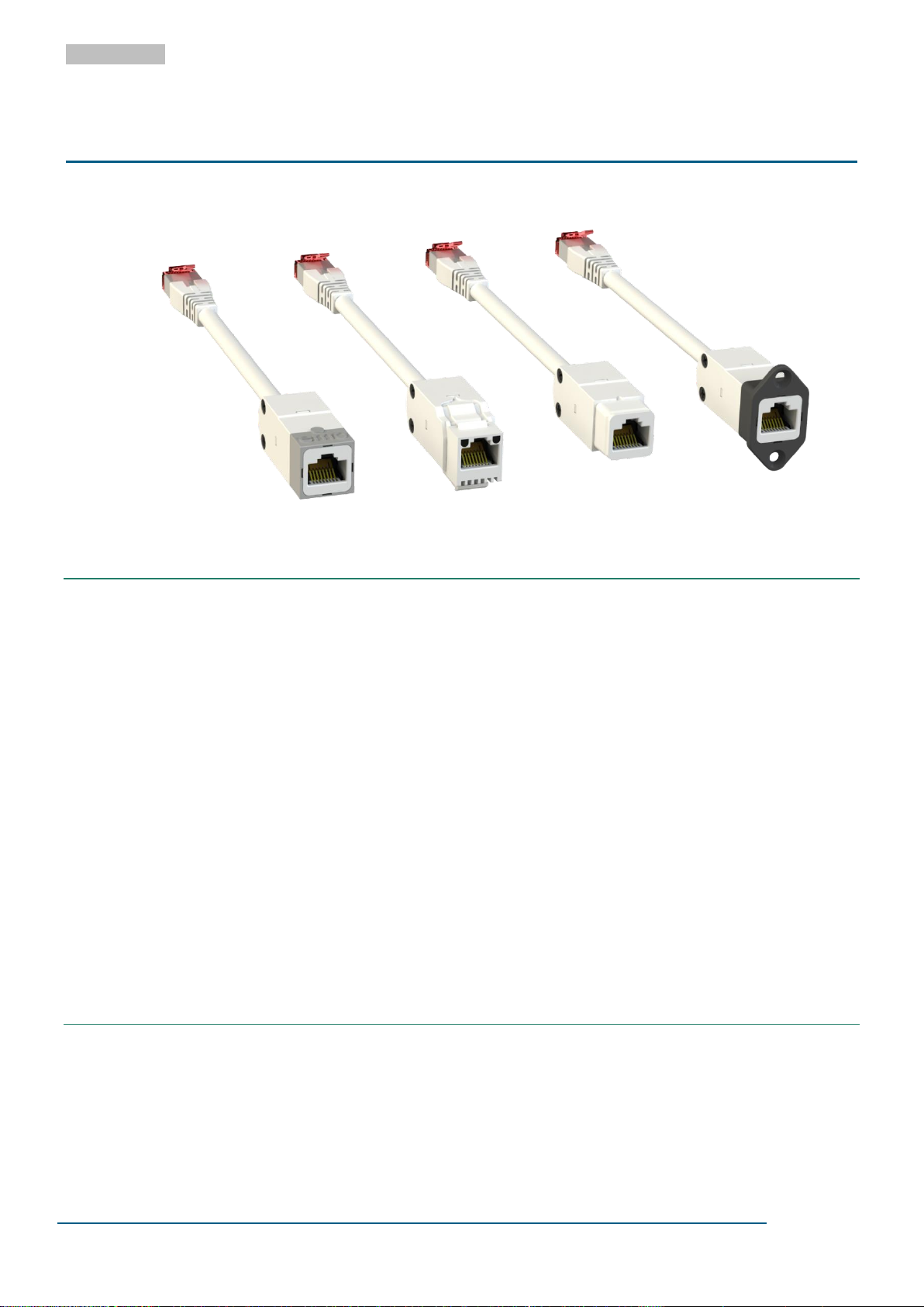
Network Isolators with Cable
EN-66e, EN-66K, EN-66S and EN-66S mit Z-4-SF-EXT
1 FEATURES AND ADVANTAGES
Available with Keystone or SnapFit interface
SnapFit accessories available for panel mounting
5.0 kV AC dielectric strength
8.5 kV DC dielectric strength
Suitable for installation into devices and racks
Suitable for use within medical devices
Designed and tested to meet IEC 60601-1
UL Recognized Component
High Performance 10Gigabit Ethernet
ISO/IEC 11801 Class EA as well as TIA/EIA-568 Cat 6A Ethernet Performance in Channel Links
Extremely low insertion losses; allowing total cable lengths of 100 meters
100% inspection by our Quality Control
Available in various cable stub lengths
Suitable for devices with supply voltages up to 400 V AC
RoHS compliant
2 GENERAL DESCRIPTION
The EMOSAFE EN-66 Network Isolator galvanically isolates every conductor (specifically the data and
shield conductors) between devices connected via a copper-based Ethernet network. The Network Isola-
tor prevents current flow resulting from differences in electrical potentials, and also protects connected
devices and their users from stray external voltages and power surges which may be directly or inductively
Page 2

PD1159-V20
Page 2 of 17
©2020 EMO Systems GmbH
EMO Systems GmbH
• Rungestr. 19
• 10179 Berlin
• Phone: +49 30 4000 475-80
• Fax: +49 30 4000 475-90
• www.emosystems.de/en
EMO Systems Inc.
• PO Box 6213
• Phone: +1 972 677 3667
• www.emosystems.com
ENGLISH
coupled onto the network lines by causes such as installation errors, lightning, switching operations, and
electrostatic discharge.
Built into a medical electrical (ME) product, the EMOSAFE EN-66 Network Isolator facilitates the safe
Ethernet connection of this ME product within the patient environment. The EN-66 satisfies all construction requirements of IEC 60601-1 in the formation of two means of patient protection (MOPP) within the
network interface, thereby practically eliminating the risk of electrical shocks arising from such stray external voltages at the network connection. With its UL approval, the EN-66 is also suitable for devices destined for export to the North American markets.
The EMOSAFE EN-66 is an efficient and compact 10Gigabit Ethernet network isolator, characterised by
exceptional Ethernet performance and a very high dielectric withstanding voltage. As a Keystone module,
it can be used in all Keystone-compatible outlet sockets, patch panels, and panel cut-outs. The construction with socket and cable stub provides the physical functionality of an extension cable.
Low-frequency signal components are strongly attenuated, protecting connected devices from ground
loops.
The EMOSAFE EN-66 Network Isolator transmits high-frequency signals through the principle of electromagnetic induction. This results in the EN-66 not requiring any external power supply. There are no software drivers to be installed.
3 APPLICATIONS
3.1 PATIENT PROTECTION
Electrical separation of Ethernet interfaces of medical electrical (ME) devices and systems, where patients
must be protected from dangerous leakage currents, in conformity with applicable standards.
3.2 EQUIPMENT PROTECTION
Applications, in which valuable or critical devices or those requiring special protection need to be protected against ripple, mains hum, and surge voltages from the network periphery.
3.3 MEASUREMENT TECHNOLOGY
Electrical measuring and monitoring equipment, which needs to be protected against external and interference voltages arising from the application environment.
3.4 POTENTIAL DIFFERENCES (TECHNICAL BUILDING SYSTEMS)
Computer systems, which are electrically connected with each other over significant distances via Ethernet cabling, where current flows caused by potential differences must be prevented.
Page 3
PD1159-V20
Page 3 of 17
©2020 EMO Systems GmbH
EMO Systems GmbH
• Rungestr. 19
• 10179 Berlin
• Phone: +49 30 4000 475-80
• Fax: +49 30 4000 475-90
• www.emosystems.de/en
EMO Systems Inc.
• PO Box 6213
• Phone: +1 972 677 3667
• www.emosystems.com
ENGLISH
EN-66
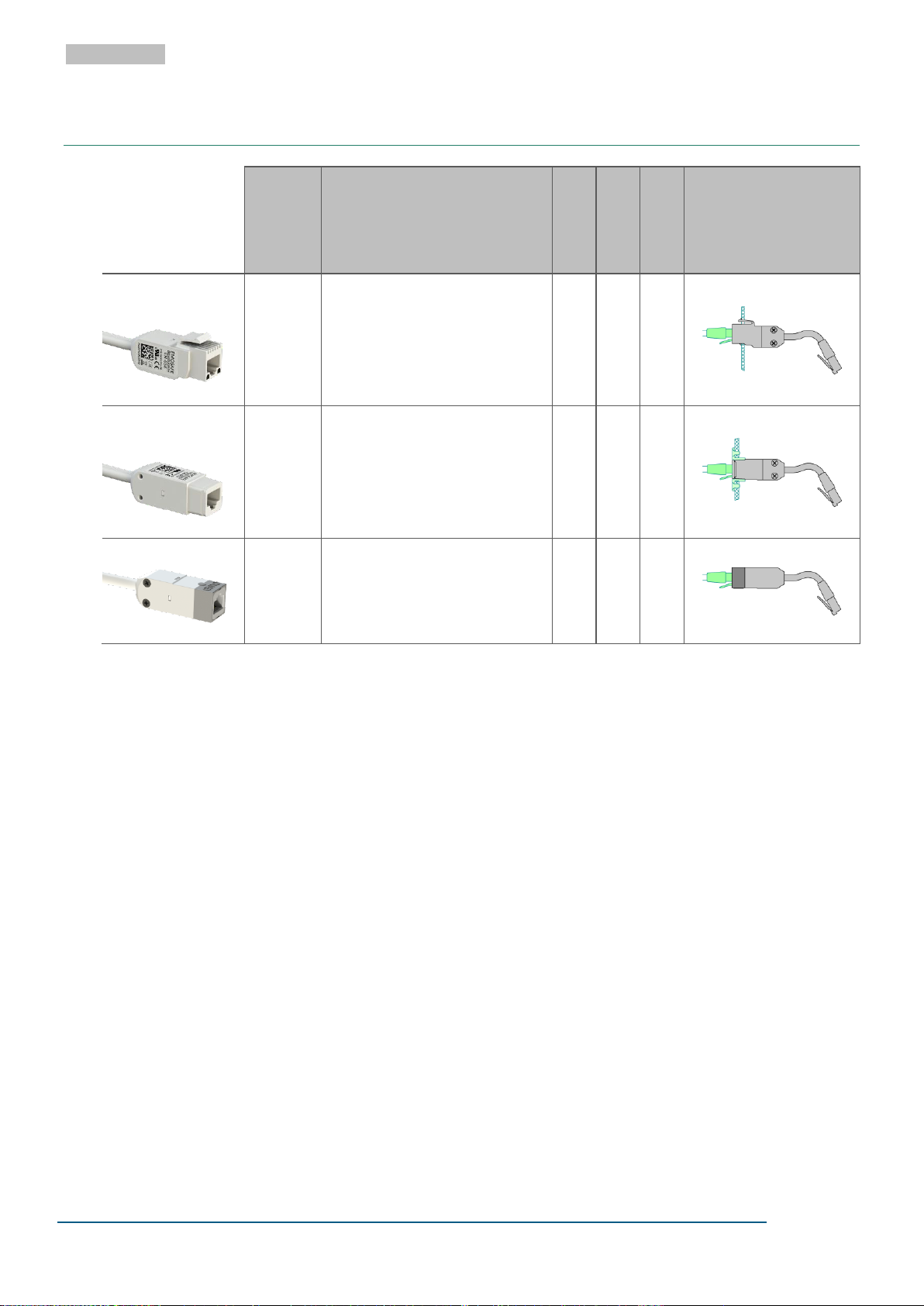
Installation Network Isolator with Cable
Name
Article
number
Special features
AC dielectric
strength (kV)
IEC 60601
-1
100/1000/
10000 Mbit/s
Configuration
Keystone
EN-66K
A10076
For use in Key-stone-compatible
outlets.
5.0
SnapFit
EN-66S
A10075
For use with EMOSAFE SnapFit
accessories.
5.0
Standalone
EN-66e
A10074
For easy upgrade of existing
equipment.
5.0
4 SUMMARY OF VARIANTS
Page 4
PD1159-V20
Page 4 of 17
©2020 EMO Systems GmbH
EMO Systems GmbH
• Rungestr. 19
• 10179 Berlin
• Phone: +49 30 4000 475-80
• Fax: +49 30 4000 475-90
• www.emosystems.de/en
EMO Systems Inc.
• PO Box 6213
• Phone: +1 972 677 3667
• www.emosystems.com
ENGLISH
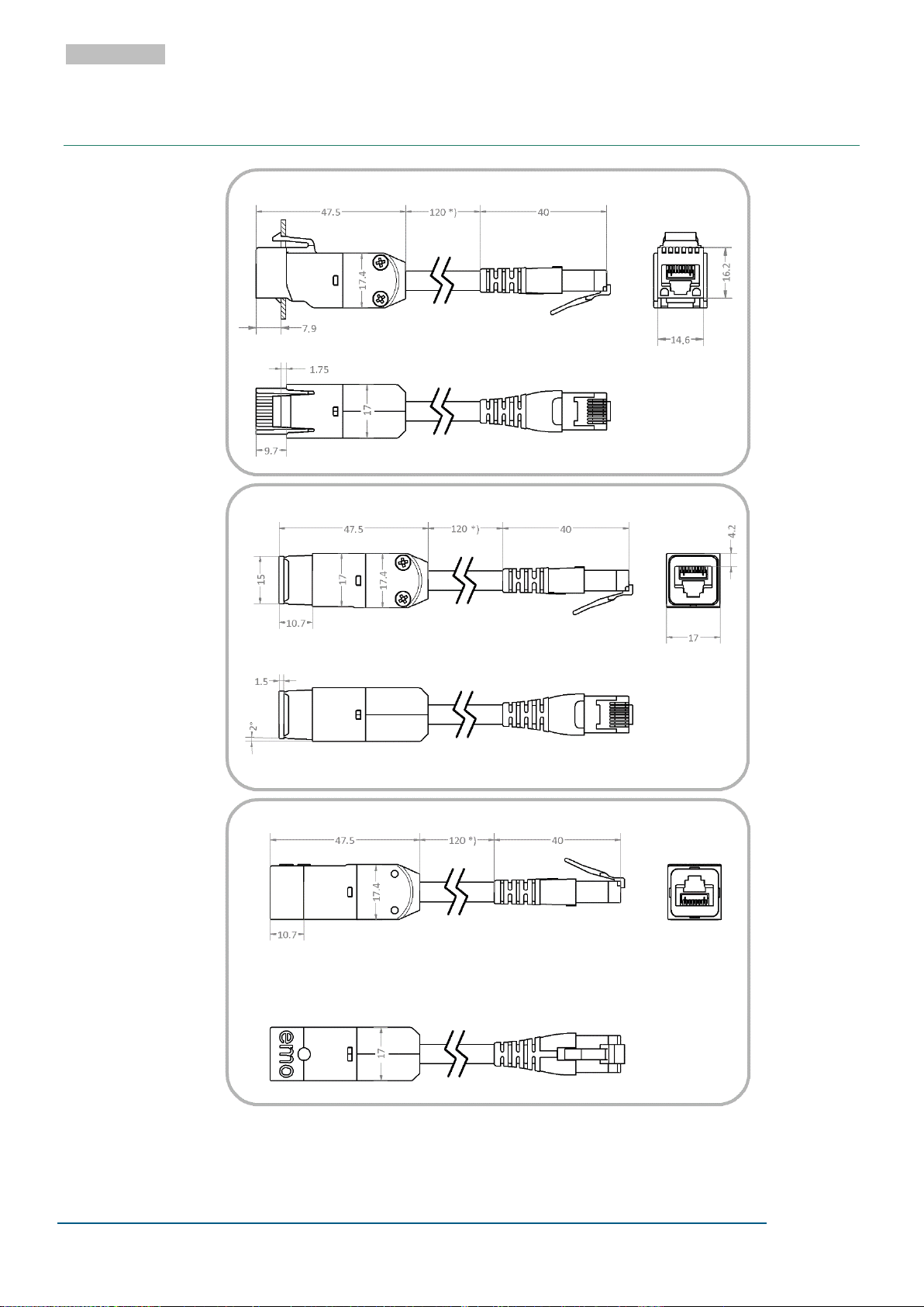
EN-66K
EN-66S
EN-66e
5 TECHNICAL DRAWINGS
Figure 1 Technical drawings for EN-66. All dimensions are in millimetres.
*) Standard cable length of 200 mm. A selection of other cable lengths from 30 mm to 10 m are available upon request.
Page 5
PD1159-V20
Page 5 of 17
©2020 EMO Systems GmbH
EMO Systems GmbH
• Rungestr. 19
• 10179 Berlin
• Phone: +49 30 4000 475-80
• Fax: +49 30 4000 475-90
• www.emosystems.de/en
EMO Systems Inc.
• PO Box 6213
• Phone: +1 972 677 3667
• www.emosystems.com
ENGLISH
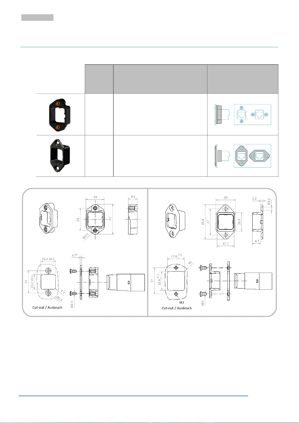
SnapFit
Installation frames for
SnapFit variants
Name
Article
number
Special features
Configuration
Z-3-SF-INT
A10057
Housing assembly for flush mounting
Two snap-fit positions
Material: polyamide, black
Two M2.5 brass inserts
Z-4-SF-EXT
A10058
Protruding housing assembly
Two snap-fit positions
Material: polyamide, black
Z-3-SF-INT Z-4-SF-EXT
6 ACCESSORIES
6.1 OVERVIEW
Figure 2 Physical dimensions and required cut-out for SnapFit installation frames. All dimensions are in millimetres.
* 1.5mm is recommended for a flush surface mounting. Other plate thicknesses are possible.
Page 6
PD1159-V20
Page 6 of 17
©2020 EMO Systems GmbH
EMO Systems GmbH
• Rungestr. 19
• 10179 Berlin
• Phone: +49 30 4000 475-80
• Fax: +49 30 4000 475-90
• www.emosystems.de/en
EMO Systems Inc.
• PO Box 6213
• Phone: +1 972 677 3667
• www.emosystems.com
ENGLISH
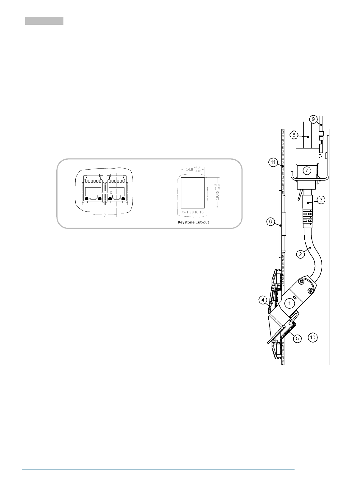
Figure 4 Keystone network
isolator in a cable duct
7 INSTALLATION
Network Isolators may only be connected to an Ethernet network via components that comply with either
EN 62368-1/ VDE 0868-1 (Information technology equipment) or IEC 60601-1 (Medical electrical equipment).
7.1 EN-66K
The Network Isolator EN-66K can be snapped into any housing aperture
which corresponds to the Keystone dimension requirements shown in Figure
1. It is therefore compatible with many wall outlets and rack systems from
various manufacturers and is especially suitable for use within cable ducts
and medical supply units.
Figure 3 Dimensions for Keystone-compatible cut-outs.
Figure 4 shows a typical assembly within a cable duct ⑩, with cover ⑪. The
Network Isolator EN-66K ① is shown installed in a Keystone-compatible wall
outlet, which usually consists of a support frame ⑤ and a plastic front panel
④. The RJ45 plug ③ of the Network Isolator is to be inserted into a RJ45
jack module termination ⑦ at the end of the permanently installed data cable ⑧. When retrofitting the Network Isolator EN-66K ① into network
channels, the existing RJ45 jack module from the wall outlet can be shifted
back within the cable duct ⑩ and used as the connection to the Network
Isolator.
The interface at the RJ45 jack module ⑦ between the permanently installed
cable and the Network Isolator must be kept accessible if regular safety
checks are to be conducted, or if the ability to subsequently verify the permanent installation is required. If this is not already made possible by a removable duct cover ⑪, we recommend the installation of a service access panel ⑥.
The EN-66K Network Isolator also interrupts the shield connection. Should the cable shield of the permanently installed network cable ⑧ need to be connected with the room or equipment potential, this must occur at the shifted-back RJ45 jack module ⑦, i.e. with the help of an earthing
wire ⑨.
Permanent tensile loading on the connecting cable ② is not permitted.
If it is intended that two or more EN-66K Network Isolators will be installed side by side into multiple mod-
ule carriers, the mounting distance "D" in Figure 3 must be taken into account. Crucial to this is the creepage distance across the dimension "X" in Figure 3, between the shield plates of the inserted RJ45 plugs.
Page 7
PD1159-V20
Page 7 of 17
©2020 EMO Systems GmbH
EMO Systems GmbH
• Rungestr. 19
• 10179 Berlin
• Phone: +49 30 4000 475-80
• Fax: +49 30 4000 475-90
• www.emosystems.de/en
EMO Systems Inc.
• PO Box 6213
• Phone: +1 972 677 3667
• www.emosystems.com
ENGLISH
The resulting creepage distance must not fall short of 8 mm (250 V AC), or 12 mm (400 V AC), as appropriate for the voltage scenario. The center-to-center distance “D” can however be reduced, if the creepage
distance across the dimension "X" is increased accordingly (e.g. by adding plastic dividers). Combining
EMOSAFE Network Isolators and non-galvanically isolated Keystone modules within module carriers is not
recommended.
7.2 EN-66S
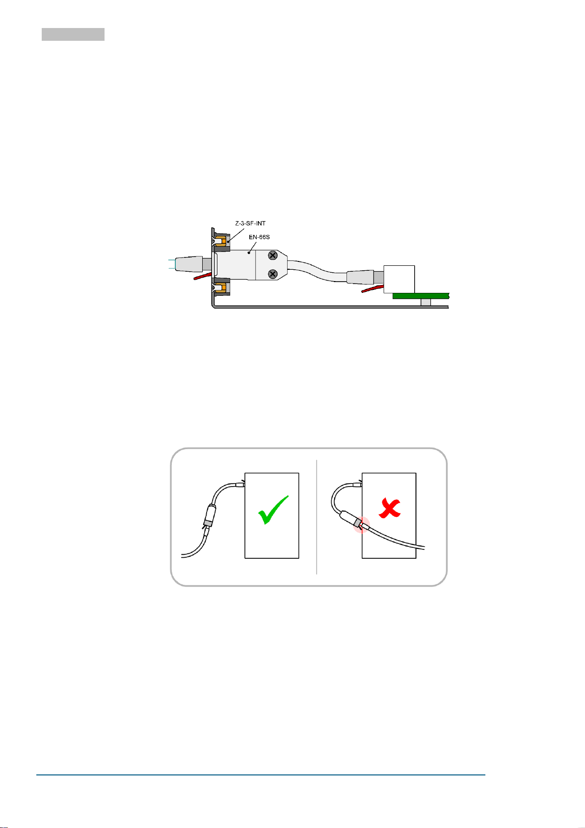
The EN-66S Network Isolator is intended for incorporation into electronic devices, and it provides a SnapFit interface for this purpose. An example configuration is shown in Figure 5.
SnapFit installation frames are available as accessories for the EN-66S; providing panel mounting which is
secure and free from play. The physically square interface allows for four different attachment positions.
The production of customer specific SnapFit frames is possible upon request.
Figure 5 Example configuration of the EN-66S installed in combination with the Snap-Fit accessory Z-3-SF-INT.
ATTENTION: SnapFit installation frames are no longer removable after being snapped into place.
7.3 EN-66e
Figure 6 Via the not isolated ending of a patch cable and the metal housing of a termination device, the ground isolation of the
The EN-66e can be used for an easy retrofit existing equipment. For best speed performance and maximal
protection, the network isolator should be placed as close as possible to the device which is supposed to
be protected.
Therefore please pay attention to the correct plug-in position when assembling!
network isolator can be accidently bypassed.
Care must be taken with cable routing in the application. By placing the isolator close to the end device
with conductive areas and using a patch cable with a large ground connection, the ground isolation of the
network isolator may accidently be bypassed (see Figure 6)
Page 8

PD1159-V20
Page 8 of 17
©2020 EMO Systems GmbH
EMO Systems GmbH
• Rungestr. 19
• 10179 Berlin
• Phone: +49 30 4000 475-80
• Fax: +49 30 4000 475-90
• www.emosystems.de/en
EMO Systems Inc.
• PO Box 6213
• Phone: +1 972 677 3667
• www.emosystems.com
ENGLISH
7.4 POWER OVER ETHERNET
The EN-66 Network Isolator can be used in a Power over Ethernet (PoE) network without restriction (however PoE devices downstream of the electrical isolation are not supplied with power).
8 SAFETY NOTICE
8.1 ASSEMBLY
During design and assembly into medical electrical systems, attention should be paid to clearance and
creepage distances, to ensure that the distances required by IEC 60601-1 are met. The isolating effect of
the Network Isolator must not be compromised by neighbouring conductive components. If, for example,
the installation of the Network Isolator is to be within a metal plate, this plate must be connected to the
ground potential (protective earth).
The EN-66 Network Isolator should always terminate a cable route. Installations that are set back within
cable ducts, as well as installations in remote patch panels, are not recommended because the protective
properties of the Network Isolator are guaranteed only directly at its own RJ45 output.
8.2 ENCLOSURE AND CONNECTION AREAS
The Network Isolator provides excellent protection between input and output, however the plastic enclosure provides only basic isolation. Furthermore, the connected plugs and the areas around the receptacles
may have metal surfaces accessible to human contact, and therefore provide no protection. If the risk
management process of the responsible organization (i.e. manufacturer or operator, as defined in IEC
60601-1) reveals unacceptable risks that operators or patients can touch the housing or exposed conducting parts while the Ethernet cabling is connected to a potentially dangerous voltage, the Network Isolator
and the exposed conducting surfaces must be surrounded with an appropriate enclosure to ensure the
required means of protection for the application.
8.3 DAMAGE AND CONTAMINATION
Damaged Network Isolators, and Network Isolators which are contaminated by dust or liquids, are to be
replaced.
9 SAFETY AND FUNCTION TESTING
9.1 FUNCTION AND COMPLIANCE TESTING
The transmission properties of permanent network installations fitted with EN-66 Network Isolators can
be checked with cable certification devices which are suitable for testing electrically isolated cable sections. To be able to conduct such an inspection, the test equipment must be configured in an AC wire-map
mode. The entire cable route, including the Network Isolator, can be tested to TIA/EIA-568 Cat 6A or
ISO 11801 Class EA as a Channel-Link. Testing of the cable shielding and the conductor resistance is not
possible in this mode. If however, these tests are required, or if the quality of the cable route itself needs
to be tested (without the Network Isolator), then testing can be performed by bypassing the Network Isolator, and connecting directly to the RJ45 socket ⑦, set back within the cable duct, as indicated in Figure
4.
Page 9

PD1159-V20
Page 9 of 17
©2020 EMO Systems GmbH
EMO Systems GmbH
• Rungestr. 19
• 10179 Berlin
• Phone: +49 30 4000 475-80
• Fax: +49 30 4000 475-90
• www.emosystems.de/en
EMO Systems Inc.
• PO Box 6213
• Phone: +1 972 677 3667
• www.emosystems.com
ENGLISH
9.2 SAFETY INSPECTIONS
Regular safety inspections and post-repair inspections are not prescribed for network isolators in medical
use, as network isolators themselves are not classified as medical electrical (ME) devices. However, together with a connected medical device, network isolators form an ME system, which altogether may be
subject to inspection. The test interval, as well as the requirements to be met for both regular safety inspections and post-repair inspections will be specified by the responsible organisation (i.e. manufacturer
or operator, as defined in IEC 60601-1), and based upon the applicable standards for the entire ME system.
To simplify implementation, the system components (in this case, the network isolator) can be individually
tested. The responsible organization provides the test parameters, specifies the test interval, and specifies
the actions to take when a component fails the test. Such an assessment may, depending upon requirements, include the following checks:
9.2.1 VISUAL INSPECTION
Check for evidence of external damage and ingress of substances, dust or liquids for example.
9.2.2 LEAKAGE CURRENT TEST
The leakage current is to be measured, to ensure that it falls within the prescribed limits. For this purpose,
test equipment which can perform equipment leakage current measurements in accordance with
IEC 62353 may be used. To perform a leakage current test, all conductors on the input side must be shortcircuited together, and all the conductors on the output side must also be short-circuited together. The AC
test voltage specified by the responsible organisation is then applied across these two connections. Input
and output sides are interchangeable. The expected current flow can be found in section 11 SPECIFICATIONS.
9.2.3 HIPOT TEST
To ensure that the device under test is not damaged, it is recommended that a DC voltage source is used
in place of the AC voltage source, and that the DC voltage is 1½ times that of the required AC voltage. The
test setup is essentially the same as that of the Leakage Current Test above. The expected dielectric
strength can be found in section 11 SPECIFICATIONS.
9.2.4 FUNCTIONAL TEST
After conducting the tests above, and reconnecting the Network Isolator into the network, an examination is recommended to ensure that the signal transmission is performing correctly. Such a functional test
can be performed, for example, with a suitable Ethernet cable certification device. Refer to the section 9.1
FUNCTION AND COMPLIANCE TESTING.
10 MODEL OPTIONS AND ORDERING INFORMATION
10.1 NOTES
The length of the flexible cable stub ② (see Figure 4 ) of the EN-66 Network Isolator is available in selected lengths from 30 mm to 10 m (inclusive). Refer to Figure 7, as well as the table in section 10.3. It is
recommended that this length be kept to a minimum. When compared to a fixed installed cable, this flexible cable stub may be more susceptible to near end crosstalk (NEXT) and alien crosstalk (AXT). The flexible
cable stub itself generates a small, but length-dependent amount of insertion loss (IL).
Page 10
PD1159-V20
Page 10 of 17
©2020 EMO Systems GmbH
EMO Systems GmbH
• Rungestr. 19
• 10179 Berlin
• Phone: +49 30 4000 475-80
• Fax: +49 30 4000 475-90
• www.emosystems.de/en
EMO Systems Inc.
• PO Box 6213
• Phone: +1 972 677 3667
• www.emosystems.com
ENGLISH
Length Groups
Step
Length Tolerance
Length Code
30, 40, … 100 mm
10 mm
± 5 mm
00030 … 00100
120, 140, … 300 mm
20 mm
± 7 mm
00120 … 00300
350, 400, … 1000 mm
50 mm
± 15 mm
00350 … 01000
1100, 1200, … 3000 mm
100 mm
± 30 mm
01100 … 03000
3500, 4000, … 10000 mm
500 mm
± 50 mm
03500 … 10000
A10076
- 0 0 4 0 0 - 1 8
0
Artikelnr.
Length Code
Angle Code
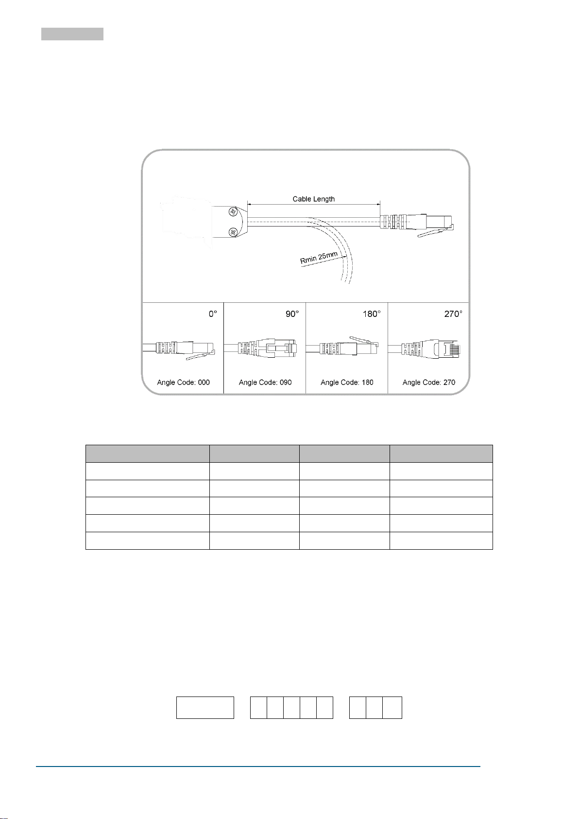
For flexible cable stub lengths between 30 mm and 500 mm (inclusive), the plug angle can be chosen, easing mechanical constraints in certain assembly configurations, and removing impermissible torsion strains
from the cable assembly. Refer to Figure 7. The manufacturing tolerance for the plug angle is ±20°.
10.2 ANGLE CODES
10.3 AVAILABLE CABLE LENGTHS
10.4 ORDER NUMBERS
When placing orders for EN-66, please specify the exact Order Code (OC). The order number is a hyphenated concatenation of the Article Number (A10068 for EN-66K, or A10069 for EN-66S), the Length Code
for the desired cable length (see section 10.3 above), and the Angle Code for the desired plug angle (see
Figure 7). For flexible cable stub lengths greater than 500 mm, the EN-66 will always be manufactured
with a plug angle of 0°, and the Angle Code can be omitted for such orders.
The following example shows the complete Order Code for an EN-66K with 400 mm cable length and a
plug angle at 180°.
Figure 7. Cable length, as well as angle codes.
Page 11
PD1159-V20
Page 11 of 17
©2020 EMO Systems GmbH
EMO Systems GmbH
• Rungestr. 19
• 10179 Berlin
• Phone: +49 30 4000 475-80
• Fax: +49 30 4000 475-90
• www.emosystems.de/en
EMO Systems Inc.
• PO Box 6213
• Phone: +1 972 677 3667
• www.emosystems.com
ENGLISH
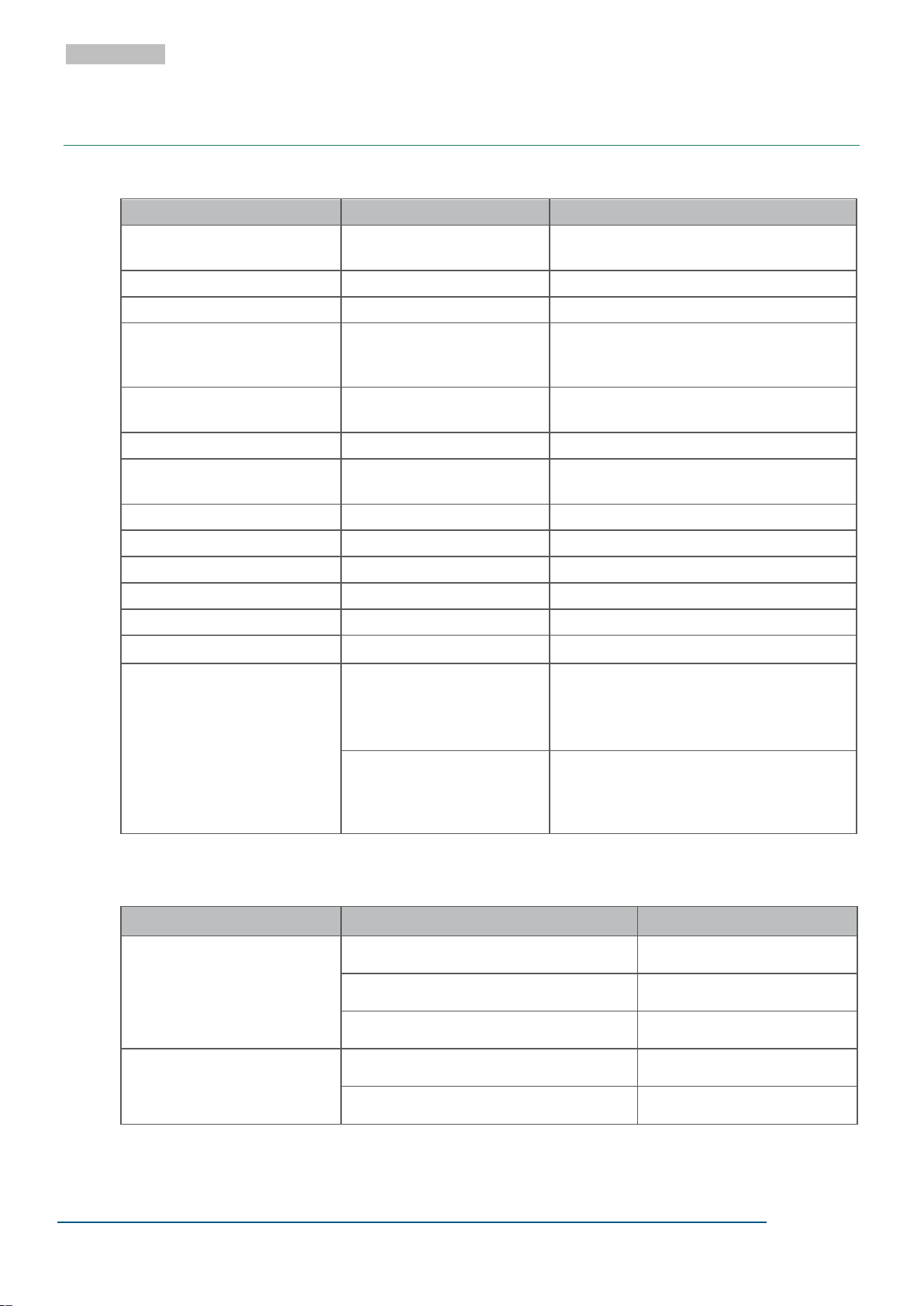
Category
Standards or Test Criteria
Property
Designation
EMOSAFE EN-66K, EMOSAFE EN-66S,
EMOSAFE EN-66e
Housing Color
White
Housing Material Plastic
Construction
EN-66K: Keystone Module with Cable
EN-66S: SnapFit Module with Cable
EN-66e: Standalone Module with Cable
Cable Length
Flexible cable segment be-
tween plug and housing
Selected lengths between 30 mm and 10 m
(inclusive). Refer to section 10.3
Minimum Bending Radius
25 mm
Maximum short-term loading
upon cable
70 N for up to 10 s
Input Interface RJ45 Jack, straight
Output Interface RJ45 Plug, cable
Weight
with 200 mm cable length
approximately 26 g
Protection Rating
EN 60529
IP40
Mating Cycles:
RJ45 plug in RJ45 socket
> 1000 cycles
Mismatched: Mating Cycles:
with RJ11 / RJ12 / RJ25
maximum of 100 cycles
Mean Time To Failure (MTTF)
SN 29500 Standard
Temperature: 25°C
Duty cycle: 100%
(24 hours, 7 days)
3,240 years
SN 29500 Standard
Temperature: 40°C
Duty cycle: 100%
(24 hours, 7 days)
3,070 years
Category
Standards or Test Criteria
Property
Transmission Speeds
and Supported Network Protocols
100 Mbit/s
100Base-T (IEEE802.3 Cl.25)
1000 Mbit/s
1000Base-T (IEEE802.3 Cl.25)
10 Gbit/s
10GBase-T (IEEE802.3 Cl.48)
Performance Category
ISO/IEC 11801
Channel Link (CH), Class
Class E
A
TIA/EIA-568
Channel Link (CH), Cat
Cat 6A
11 SPECIFICATIONS
11.1 GENERAL
11.2 ETHERNET PERFORMANCE
Page 12
PD1159-V20
Page 12 of 17
©2020 EMO Systems GmbH
EMO Systems GmbH
• Rungestr. 19
• 10179 Berlin
• Phone: +49 30 4000 475-80
• Fax: +49 30 4000 475-90
• www.emosystems.de/en
EMO Systems Inc.
• PO Box 6213
• Phone: +1 972 677 3667
• www.emosystems.com
ENGLISH
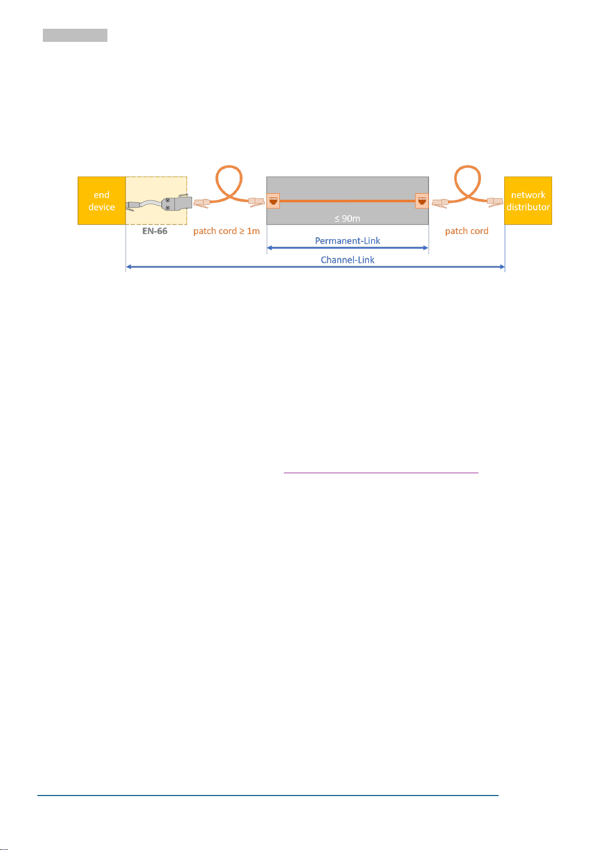
Figure 8 Recommended setup of the network isolator
Depending on the measurement parameter, the Ethernet performance of a network component is not
only dependent on the hardware component itself, but also on the transmission link in which it is installed. For this reason, the network isolators are evaluated using a realistic transmission link, the socalled Channel-Link. In order to offer maximum protection for the end device, we recommend the structure of Figure 8.
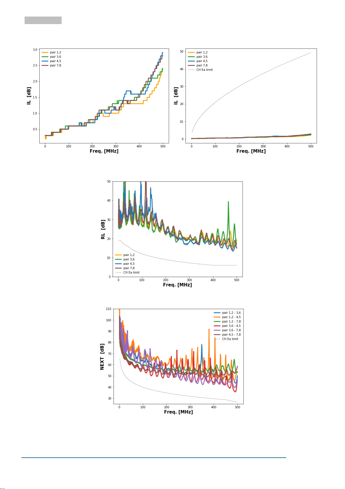
The speed is classified, among other things, by adhering to limit values for the Insertion Loss (IL), the Return Loss (RL) and Near-End-Crosstalk (NEXT) of the system setup.
The IL is fundamentally additive and the individual IL portions of all components of the system structure
can be added up. Figure 9 and Figure 10 show the IL of the network isolator without the remaining Channel-Link components. Figure 11 and Figure 12 show the RL and the NEXT performance of the recommended structure on the end device side. The RL and the NEXT depend strongly on the structure of the
system and do not behave additively with the rest of the structure.
More detailed information on system setup, classifications, performance and the basics of the individual
parameters can be found in our white paper "Ethernet Performance of Network Isolators".
Page 13
PD1159-V20
Page 13 of 17
©2020 EMO Systems GmbH
EMO Systems GmbH
• Rungestr. 19
• 10179 Berlin
• Phone: +49 30 4000 475-80
• Fax: +49 30 4000 475-90
• www.emosystems.de/en
EMO Systems Inc.
• PO Box 6213
• Phone: +1 972 677 3667
• www.emosystems.com
ENGLISH
Figure 9 Insertion Loss of an EN-66
Figure 10 Insertion Loss of an EN-66 with the
Class EA Channel-Link Limit
Figure 11 Return Loss of an EN-66 on the end device side of the setup of the recommended setup
Figure 12 NEXT-Performance Loss of an EN-66 on the end device side of the setup of the recommended setup
Page 14
PD1159-V20
Page 14 of 17
©2020 EMO Systems GmbH
EMO Systems GmbH
• Rungestr. 19
• 10179 Berlin
• Phone: +49 30 4000 475-80
• Fax: +49 30 4000 475-90
• www.emosystems.de/en
EMO Systems Inc.
• PO Box 6213
• Phone: +1 972 677 3667
• www.emosystems.com
ENGLISH
Category
Standards or Test Criteria
Property
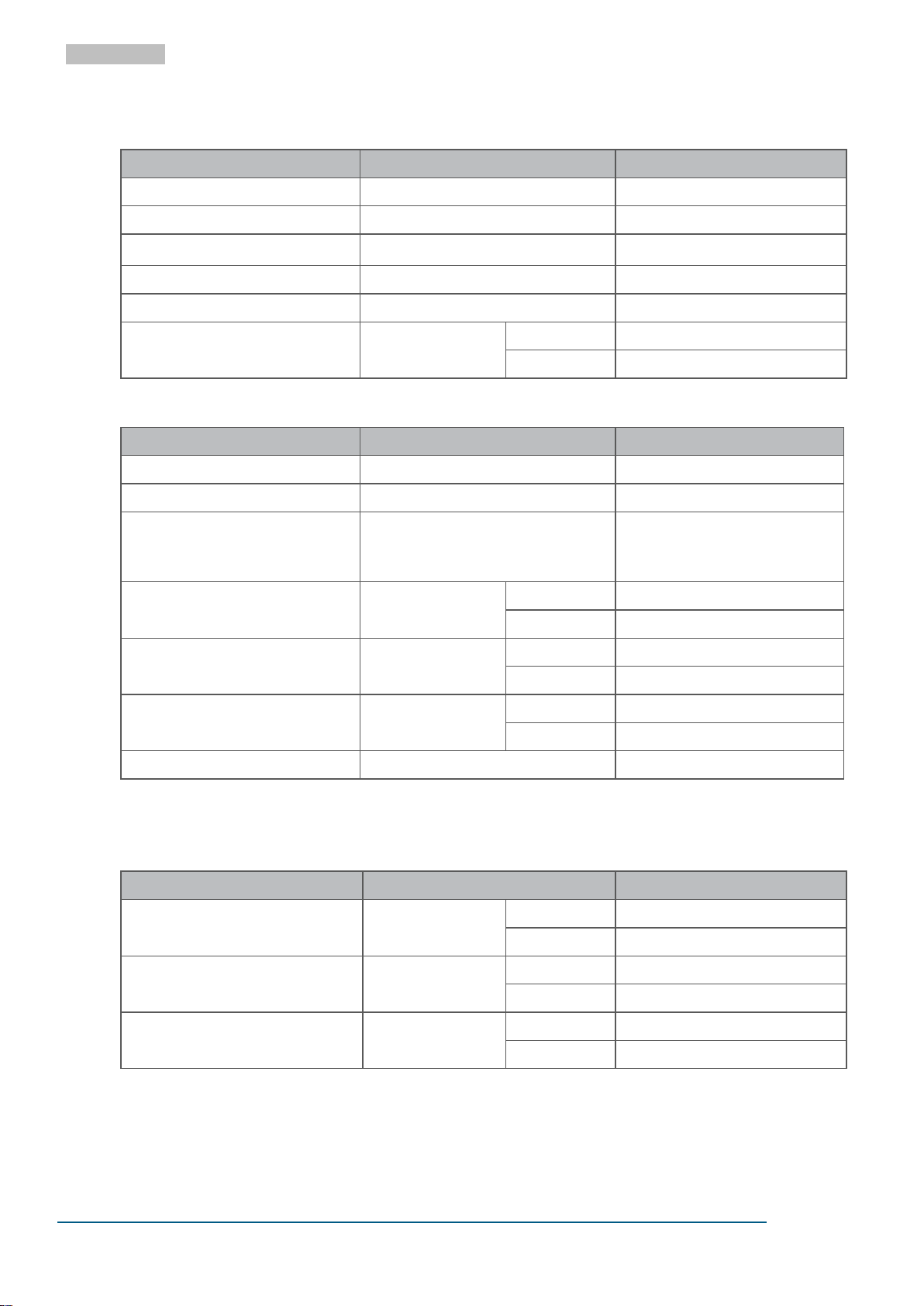
AC Dielectric Strength
@ 50 Hz, for 60 s
5.0 kV
DC Dielectric Strength
for 60 s
8.5 kV
Reinforced Isolation
IEC 60601-1
Coupling Capacitance / Channel
15 pF ±25%
Total Coupling Capacitance
60 pF ±25%
Total Leakage Current
275 V AC @ 50 Hz
Typical:
12.0 µA
Maximum:
16.0 µA
Category
Standards or Test Criteria
Property
Pollution Degree
IEC 61010
21
Overvoltage Category
IEC 60664-1
III
Maximum Working Voltage2
Maximum mains voltage of the
connected devices, in accordance
with IEC 60601-1
400 V AC
450 V DC
Temperature
Min.:
-10°C
Max.:
+60°C
Air Humidity
Non-condensing
Min.:
10%
Max.:
90%
Air Pressure
Min.:
700 hPa
Max.:
1,060 hPa
Altitude
Max.:
3,200 m
Category
Standards or Test Criteria
Property
Temperature
Min.:
-40°C
Max.:
+70°C
Air Humidity
Non-condensing
Min.:
10%
Max.:
90%
Air Pressure
Min.:
500 hPa
Max.:
1,060 hPa
11.3 ELECTRICAL
11.4 OPERATING CONDITIONS AND AREA OF APPLICATION
1
Normally only nonconductive pollution occurs. Temporary conductivity caused by condensation is to be expected.
2
The Network Isolator can be permanently exposed to this voltage level.
11.5 ENVIRONMENTAL CONDITIONS: STORAGE AND TRANSPORTATION
Page 15
PD1159-V20
Page 15 of 17
©2020 EMO Systems GmbH
EMO Systems GmbH
• Rungestr. 19
• 10179 Berlin
• Phone: +49 30 4000 475-80
• Fax: +49 30 4000 475-90
• www.emosystems.de/en
EMO Systems Inc.
• PO Box 6213
• Phone: +1 972 677 3667
• www.emosystems.com
ENGLISH
Category
Property
UL Recognized Component
UL File No.
E362969
IEC 60601-1
IEC 60601-1-2
ANSI/AAMI ES 60601-1
CAN/CSA-C22.2 No. 60601-1
Low Voltage Directive
EMC Directive
RoHS Directive
Area
Number and
type of Means
of Protection
Material
Group
(from CTI)
Maximum
Operating Voltage
Required
creepage
distance
(mm)
Required
clearance
distance
(mm)
Measured
creepage
distance
(mm)
Measured
clearance
distance
(mm)
V AC
V
peak
A
2 MOPP 1
IIIb 2
400
565
12.0
7.0
12.0
9.0
A
Ethernet
Input/Output
Ethernet
Input/Output
Plastic enclosure
11.6 CERTIFICATES
The versions of the cited standards and directives to which our products comply with can be found in our
Declaration of Conformity and our UL certificate on our website under "Standard Conformity and Certifi-
cates".
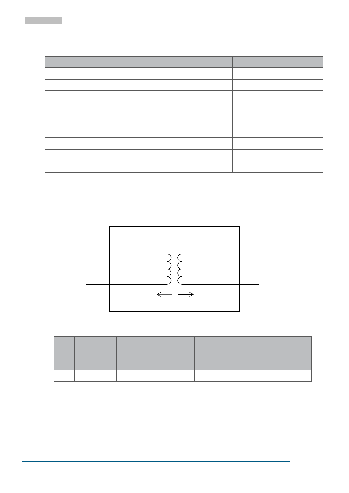
11.7 ISOLATION DIAGRAM
Figure 13. Isolation diagram for EN-66
1
MOPP = Means of Patient Protection
2
Materials in the Material Group IIIb have a Comparative Tracking Index (CTI) value between 100 and 175.
Page 16
PD1159-V20
Page 16 of 17
©2020 EMO Systems GmbH
EMO Systems GmbH
• Rungestr. 19
• 10179 Berlin
• Phone: +49 30 4000 475-80
• Fax: +49 30 4000 475-90
• www.emosystems.de/en
EMO Systems Inc.
• PO Box 6213
• Phone: +1 972 677 3667
• www.emosystems.com
ENGLISH
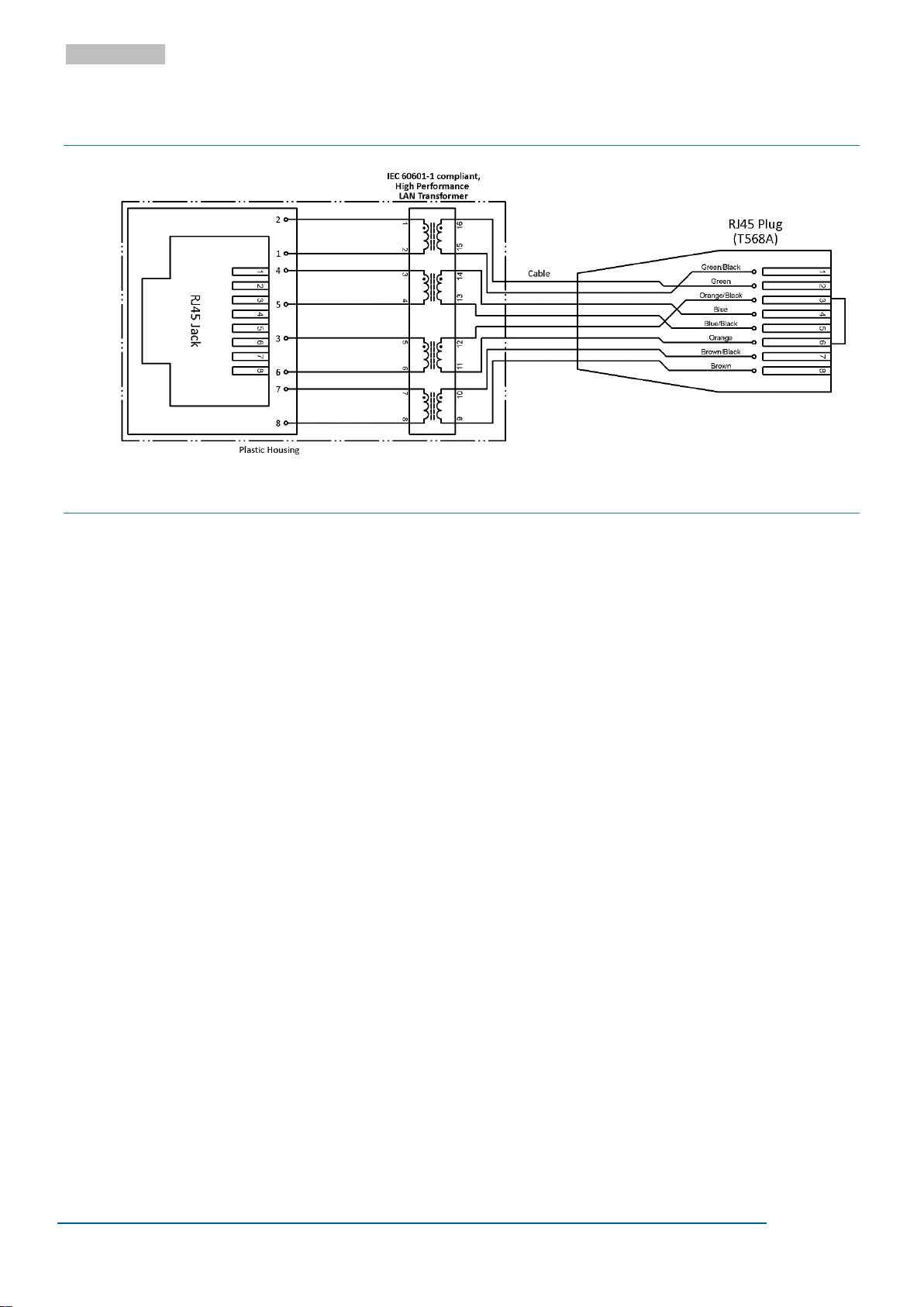
12 SCHEMATIC DIAGRAM
13 PACKAGING
Contents:
One of: EN-66K or EN-66S
Installation Guide
A packaging label provides the following information:
Article Description
Quantity
Cable Length (for customer specific products)
Plug Angle (for customer specific products)
Part Number (PN) (or Order Code (OC) for customer specific products)
Date of Manufacture
Serial Number (SN)
The Serial Number is printed as both a linear (Code 128) and a 2-D Barcode (Data Matrix)
Page 17
PD1159-V20
Page 17 of 17
©2020 EMO Systems GmbH
EMO Systems GmbH
• Rungestr. 19
• 10179 Berlin
• Phone: +49 30 4000 475-80
• Fax: +49 30 4000 475-90
• www.emosystems.de/en
EMO Systems Inc.
• PO Box 6213
• Phone: +1 972 677 3667
• www.emosystems.com
ENGLISH
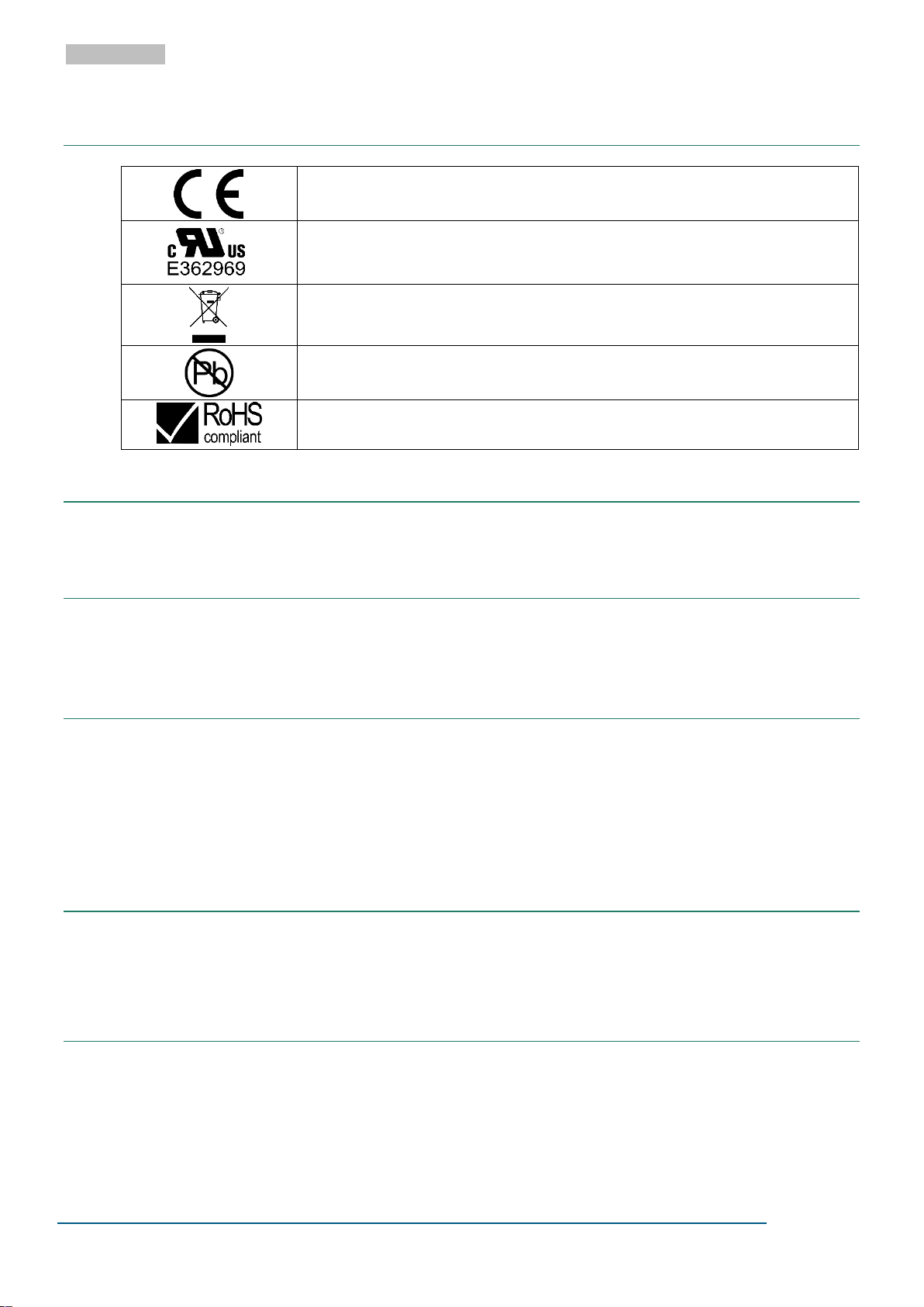
Through this mark, the conformity of the product with all applicable EU Directives is
confirmed.
Designates the product as a UL "Recognized Component";
File number E362969.
The product may not be disposed of in domestic rubbish.
This product contains no substances containing lead and is manufactured using leadfree solder.
This product meets the requirements of EU Directive concerning the limitation of the
use of certain hazardous substances in electric and electronic equipment.
14 PRODUCT MARKINGS
15 SCHEDULED MAINTENANCE
When used as directed, EMOSAFE Network Isolators are maintenance-free.
16 ENVIRONMENTAL PROTECTION INFORMATION
This device contains electronic components. At the end of its service life it is to be returned to the manufacturer for disposal.
17 QUALITY
EMO Systems operates a certified quality management system for development and production in accordance with ISO 9001 and ISO 13485. Prior to delivery, each Network Isolator is subjected to a comprehensive quality inspection. This inspection ensures, among other factors, that the attained values for leakage
currents, dielectric withstand strengths, insertion losses, return losses, and near end crosstalk values all
meet the specified requirements.
18 CONTACT AND SUPPORT
Please find our up-to-date contact details on our website: http://www.emosystems.de/en/contact
Or send us an e-mail at the following address: [email protected]
19 LEGAL NOTIFICATION
The information provided above in this datasheet has been compiled with all due care and is believed to
be accurate and reliable. However, we cannot guarantee that the information contained is completely
free from error. The end user is responsible and liable for the proper use of this product. EMO Systems
GmbH assumes no liability. We reserve the right to make changes to this datasheet without notice.
 Loading...