

Page 1
PD 1056-V20
Page 1/23
© 2013 EMO Systems GmbH
EMO S ystems GmbH • Rungestr. 19 • 10179 Berlin • Germany • Tel.: +49 . 30 . 4000 475-80 • Fax: +49 . 30 . 4000 475-90 • [email protected] • www.emosystems.de
ENGLISH
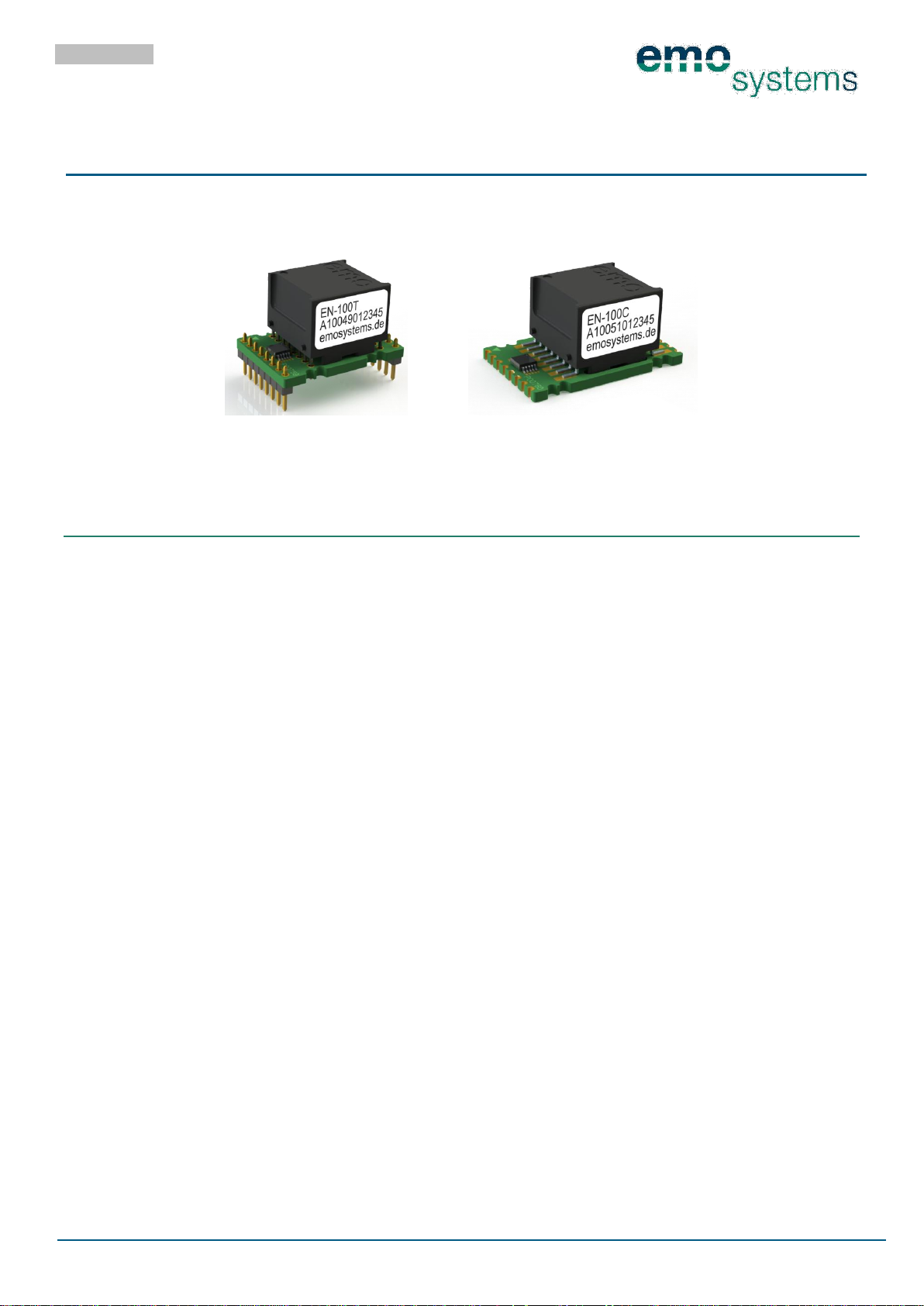
EMOSAFE EN-100
Product Data Sheet
Network Isolators for PCB assembly
November 2013
1 GENERAL DESCRIPTION
The EMOSAFE EN-100 Network Isolator interrupts all galvanically conducting connections (conductors and
shielding) between the Ethernet input socket and the Ethernet circuit of the device being protected. They
prevent potential equalisation currents and protect devices and their users from transient excess voltages
which have been coupled directly or inductively into the Ethernet network line through errors in installation, lightning strikes, switching operations, electrostatic discharges and so on.
EMOSAFE EN-100 Network Isolators are meant to be integrated into the PCB of the device being protected. There are models available for plug-in assembly with socket strips and models that can be permanently soldered. Their extremely compact design also allows them to be used in situations where there is very
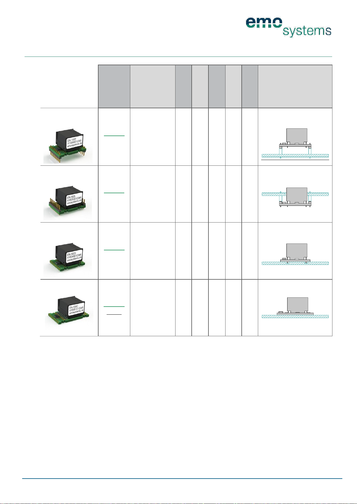
limited space. A summary of the available variants can be found in Section 4 SUMMARY OF VARIANTS
All EN-100 models provide especially effective device protection thanks to the implementation of additional TVS diode circuitry. Voltage spikes on single conductors cannot be suppressed using conventional
network isolators However, even these are eliminated when using the EN-100.
Devices in the EN-100 series meet the requirements of IEC 60601-1 (3rd Edition) and IEC 60601-1-2 and as
such are suitable for providing the galvanic separation of Ethernet interfaces for devices used in the field
of medicine.
EMOSAFE Network Isolators transmit high-frequency AC voltages using the principle of electromagnetic
induction in the frequency range used for data transmission. Due to this transmission principle, they do
not require their own power supply. The installation of drivers is not required.
Low-frequency signal components are strongly attenuated, so that connected devices may, for example,
be protected against ground loops.
Page 2
PD 1056-V20
Page 2/23
© 2013 EMO Systems GmbH
EMO Systems GmbH • Rungestr. 19 • 10179 Berlin • Germany • Tel.: +49. 30. 4000 475-80 • Fax: +49. 30. 4000 475-90 • [email protected] • www.emosystems.de
2 FEATURES AND ADVANTAGES
For PCB assembly, pluggable or solderable
Ultracompact
Gigabit Ethernet
4.6 kV AC dielectric strength
8.5 kV DC dielectric strength
Suitable for devices with a supply voltage of up to 400 V AC
Limitation of transient excess voltages on signal lines with use of TVS diodes
Extremely low Insertion Loss
Conforms to IEC 60601-1 (3
rd
Edition)
Reinforced insulation in accordance with IEC 60601-1
CE marking
UL Recognized Component
3 APPLICATIONS
3.1 PATIENT PROTECTION
Galvanic separation of Ethernet interfaces from medical electrical devices/systems where patients must
be protected from dangerous leakage currents in conformity with applicable standards.
3.2 EQUIPMENT PROTECTION
Protection of particularly valuable devices from ripple voltages and excess voltages from the periphery of
the network.
3.3 MEASUREMENT TECHNOLOGY
Protection of electrical measuring and monitoring equipment from external and interference voltages
arising from the Ethernet cabling.
3.4 AUDIO
Reduction of low-frequency AC voltages (mains hum) which are caused by the mains connection to an imperceptible degree.
Page 3
PD 1056-V20
Page 3/23
© 2013 EMO Systems GmbH
EMO Systems GmbH • Rungestr. 19 • 10179 Berlin • Germany • Tel.: +49. 30. 4000 475-80 • Fax: +49. 30. 4000 475-90 • [email protected] • www.emosystems.de
EN-100
Network Isolators
for PCB assembly
Name
Article
number
Special features
Dielectric strength
in kV (AC)
TVS diodes
10/100/1000
Mbit
Return Loss @
100MHz in dB
Insertion Loss @
100MHz in dB
Configuration
Pluggable
EN-100T
A10049
Especially short;
downwardspointing pin
connectors to be
plugged or soldered; THT transformer
4.6
>14
<1
Pluggable
EN-100L
A10050
Especially short;
upwardspointing pin
connectors to be
plugged or soldered; THT transformer
4.6
>14
<1
Solderable
EN-100S
A10048
Especially short;
edge soldering
points for manual soldering to
the solder pads;
THT transformer
4.6
>14
<1
Solderable
EN-100C
A10051
Edge soldering
points for manual soldering to
the solder pads;
SMD transformer; no milling of
the carrier PCB
necessary
4.6
>14
<1
4 SUMMARY OF VARIANTS
Page 4
PD 1056-V20
Page 4/23
© 2013 EMO Systems GmbH
EMO Systems GmbH • Rungestr. 19 • 10179 Berlin • Germany • Tel.: +49. 30. 4000 475-80 • Fax: +49. 30. 4000 475-90 • [email protected] • www.emosystems.de
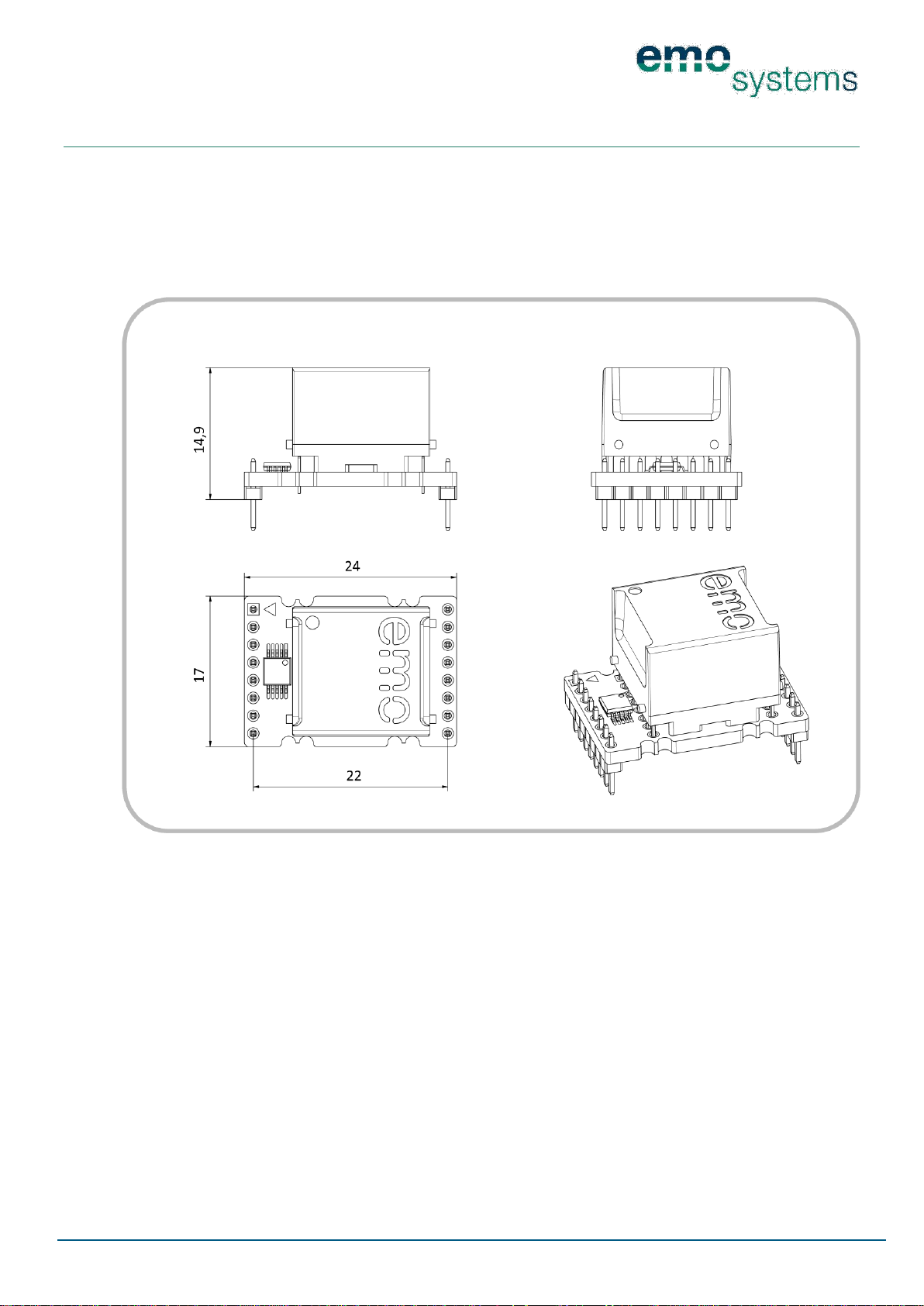
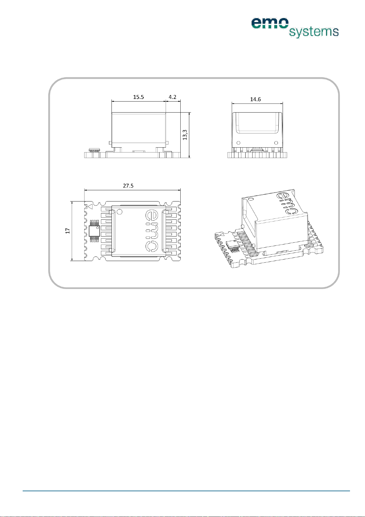
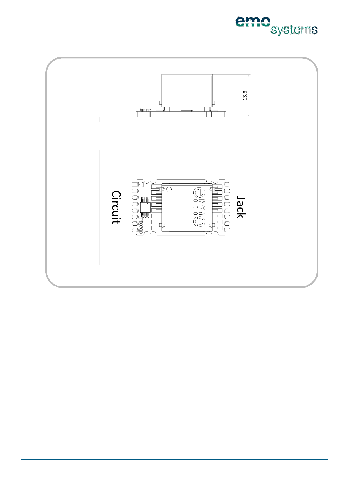
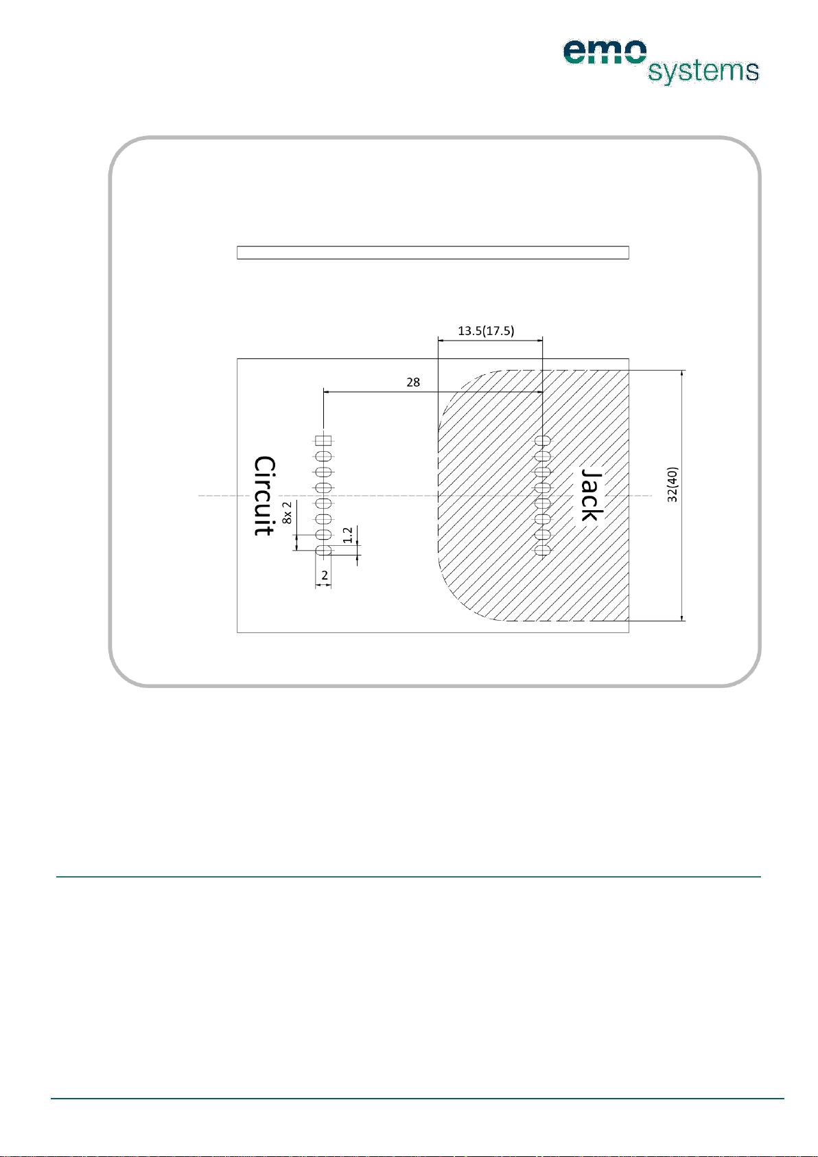
5 DRAWINGS
All dimensions in millimetres
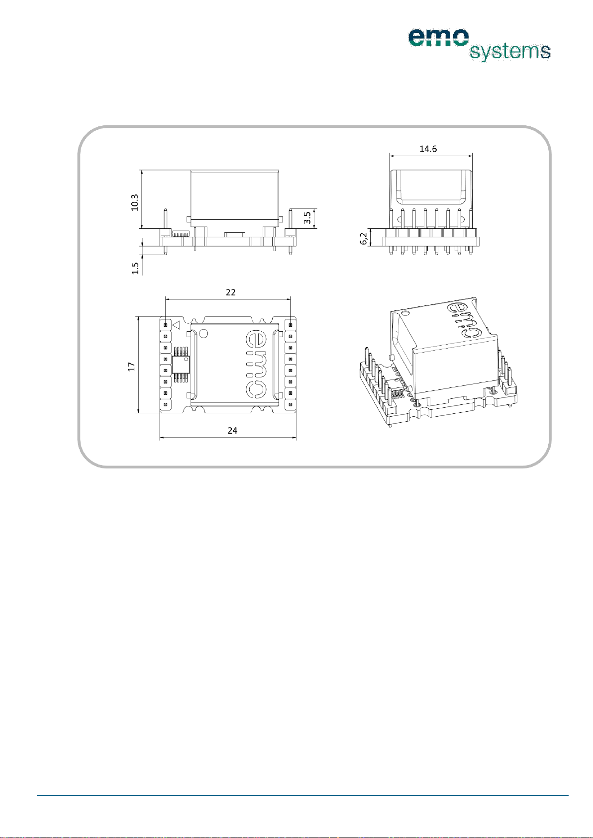
5.1 EN-100T
5.1.1 EN-100T MODULE DIMENSIONS
Page 5
PD 1056-V20
Page 5/23
© 2013 EMO Systems GmbH
EMO Systems GmbH • Rungestr. 19 • 10179 Berlin • Germany • Tel.: +49. 30. 4000 475-80 • Fax: +49. 30. 4000 475-90 • [email protected] • www.emosystems.de
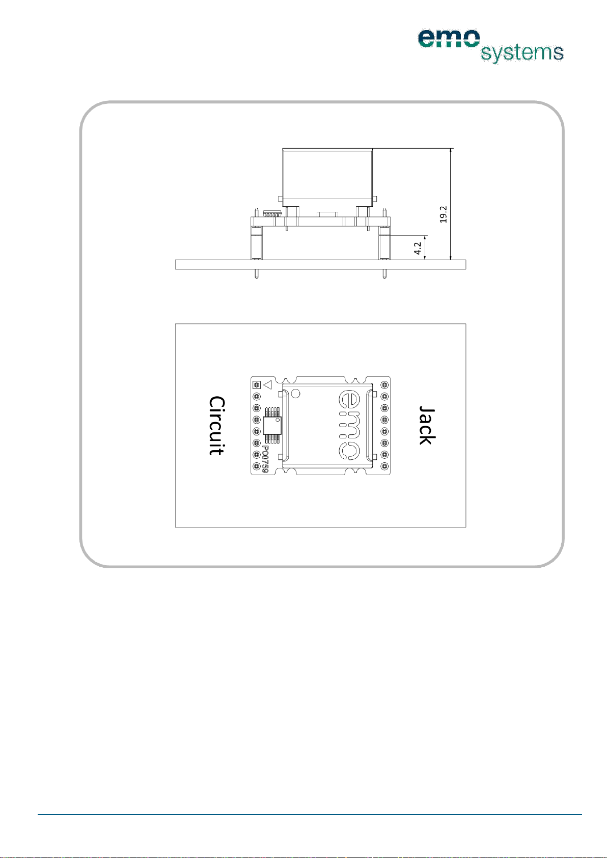
5.1.2 EN-100T FITTING DIMENSIONS
The pin connectors can be soldered directly into the PCB or, as illustrated, be plugged into a socket strip.
This dimensioned drawing illustrates a socket strip with a height of 4.2 mm. The assembly height is reduced by this amount if a socket strip is not used.
Page 6
PD 1056-V20
Page 6/23
© 2013 EMO Systems GmbH
EMO Systems GmbH • Rungestr. 19 • 10179 Berlin • Germany • Tel.: +49. 30. 4000 475-80 • Fax: +49. 30. 4000 475-90 • [email protected] • www.emosystems.de
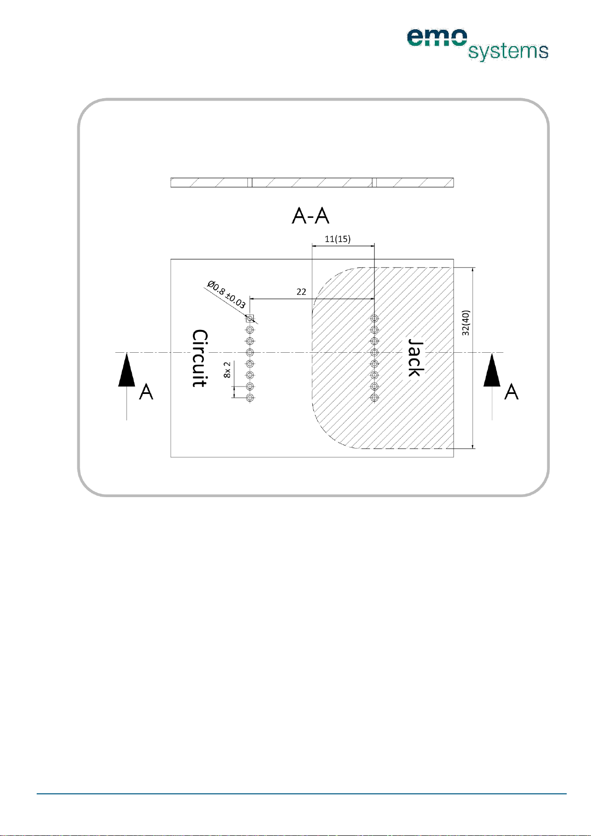
5.1.3 EN-100T PCB LAYOUT
No conducting paths should be placed in the shaded area as this would reduce the leakage distance to inadmissible values. The dimensions given for the shaded area refer to the requirements for the provision
of two protective measures for patient protection for devices with a voltage rating of 250 V(400 V). However, the actual requirements for the clearance and leakage distance vary, and have to be determined and
checked depending on the device. The assembly of the Network Isolators in a manner that satisfies requirements and the relevant standards is the responsibility of the device manufacturer.
Page 7
PD 1056-V20
Page 7/23
© 2013 EMO Systems GmbH
EMO Systems GmbH • Rungestr. 19 • 10179 Berlin • Germany • Tel.: +49. 30. 4000 475-80 • Fax: +49. 30. 4000 475-90 • [email protected] • www.emosystems.de
5.2 EN-100L
5.2.1 EN-100L MODULE DIMENSIONS
Page 8
PD 1056-V20
Page 8/23
© 2013 EMO Systems GmbH
EMO Systems GmbH • Rungestr. 19 • 10179 Berlin • Germany • Tel.: +49. 30. 4000 475-80 • Fax: +49. 30. 4000 475-90 • [email protected] • www.emosystems.de
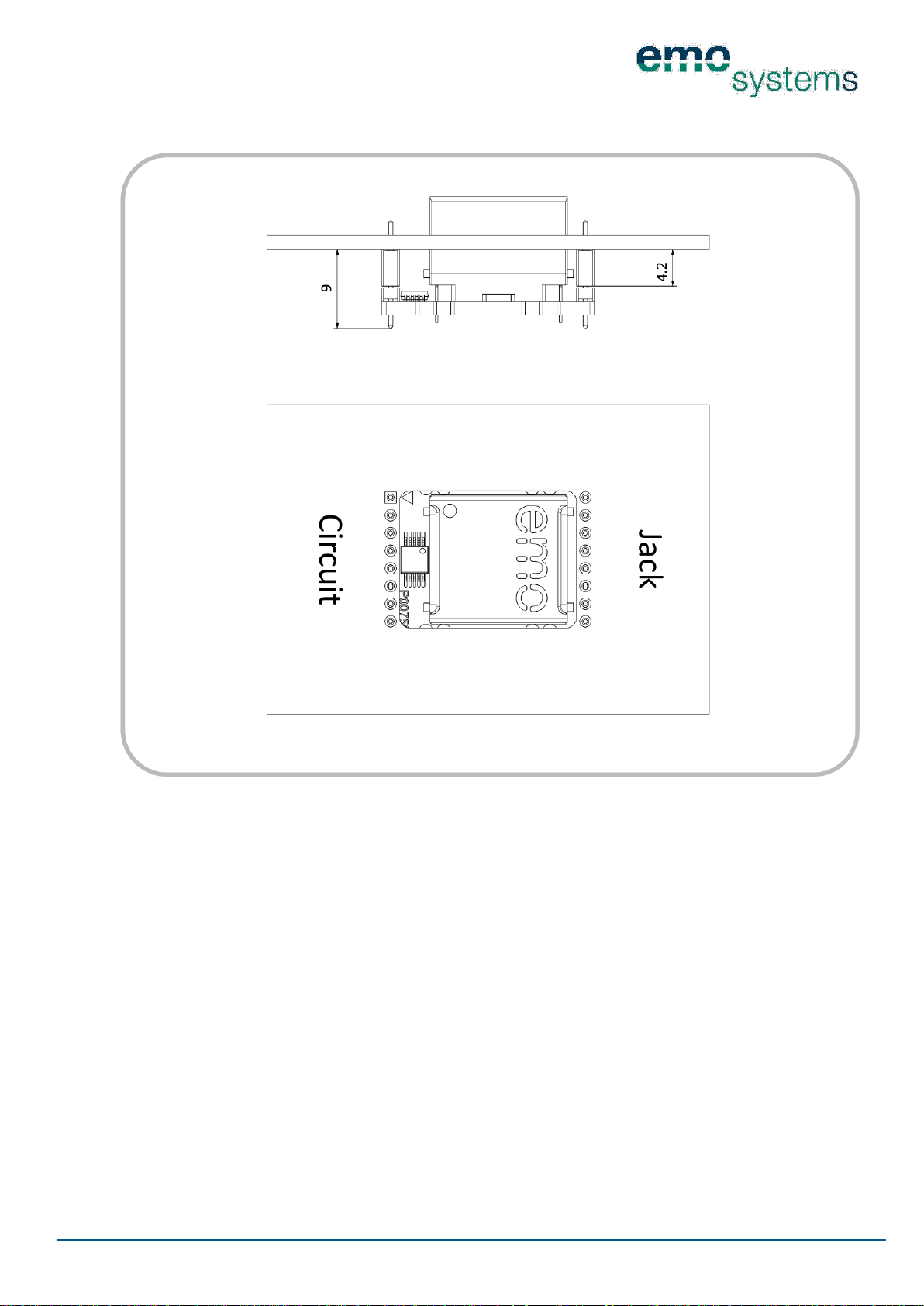
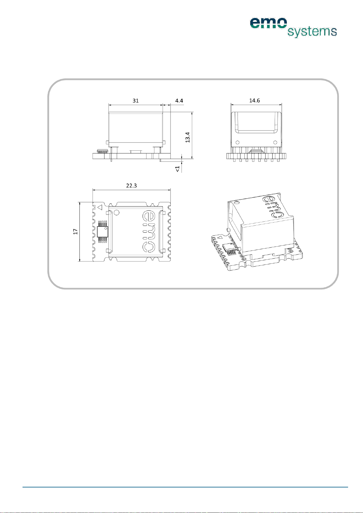
5.2.2 EN-100L FITTING DIMENSIONS
The pin connectors can be soldered directly into the PCB or, as illustrated, be plugged into a socket strip.
This dimensioned drawing illustrates a socket strip with a height of 4.2 mm. The assembly height is
changed by this amount if a socket strip is not used.
Page 9
PD 1056-V20
Page 9/23
© 2013 EMO Systems GmbH
EMO Systems GmbH • Rungestr. 19 • 10179 Berlin • Germany • Tel.: +49. 30. 4000 475-80 • Fax: +49. 30. 4000 475-90 • [email protected] • www.emosystems.de
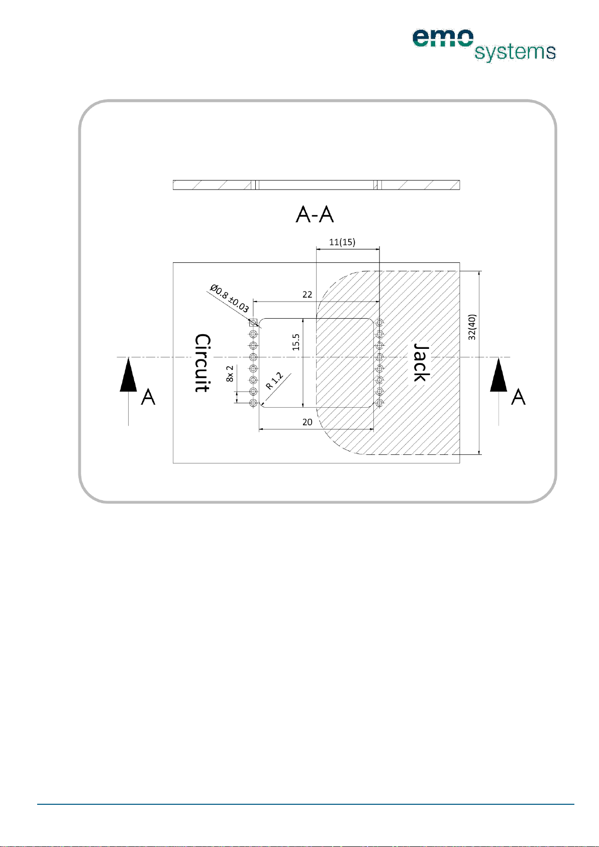
5.2.3 EN-100L PCB LAYOUT
No conducting paths should be placed in the shaded area as this would reduce the leakage distance to inadmissible values. The dimensions given for the shaded area refer to the requirements for the provision
of two protective measures for patient protection for devices with a voltage rating of 250 V (400 V). However, the actual requirements for the clearance and leakage distance vary, and have to be determined and
checked depending on the device. The assembly of the Network Isolators in a manner that satisfies requirements and the relevant standards is the responsibility of the device manufacturer.
Page 10
PD 1056-V20
Page 10/23
© 2013 EMO Systems GmbH
EMO Systems GmbH • Rungestr. 19 • 10179 Berlin • Germany • Tel.: +49. 30. 4000 475-80 • Fax: +49. 30. 4000 475-90 • [email protected] • www.emosystems.de
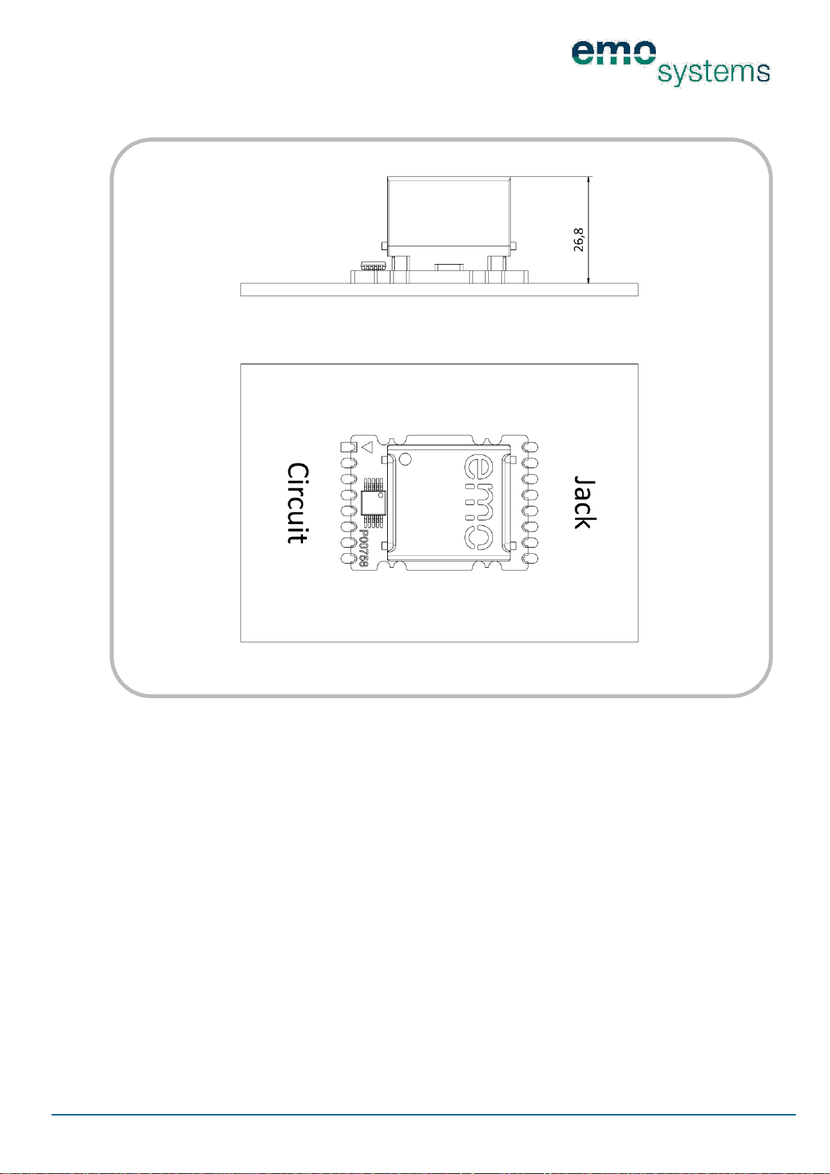
5.3 EN-100S
5.3.1 EN-100S MODULE DIMENSIONS
Page 11
PD 1056-V20
Page 11/23
© 2013 EMO Systems GmbH
EMO Systems GmbH • Rungestr. 19 • 10179 Berlin • Germany • Tel.: +49. 30. 4000 475-80 • Fax: +49. 30. 4000 475-90 • [email protected] • www.emosystems.de
5.3.2 EN-100S FITTING DIMENSIONS
Page 12
PD 1056-V20
Page 12/23
© 2013 EMO Systems GmbH
EMO Systems GmbH • Rungestr. 19 • 10179 Berlin • Germany • Tel.: +49. 30. 4000 475-80 • Fax: +49. 30. 4000 475-90 • [email protected] • www.emosystems.de
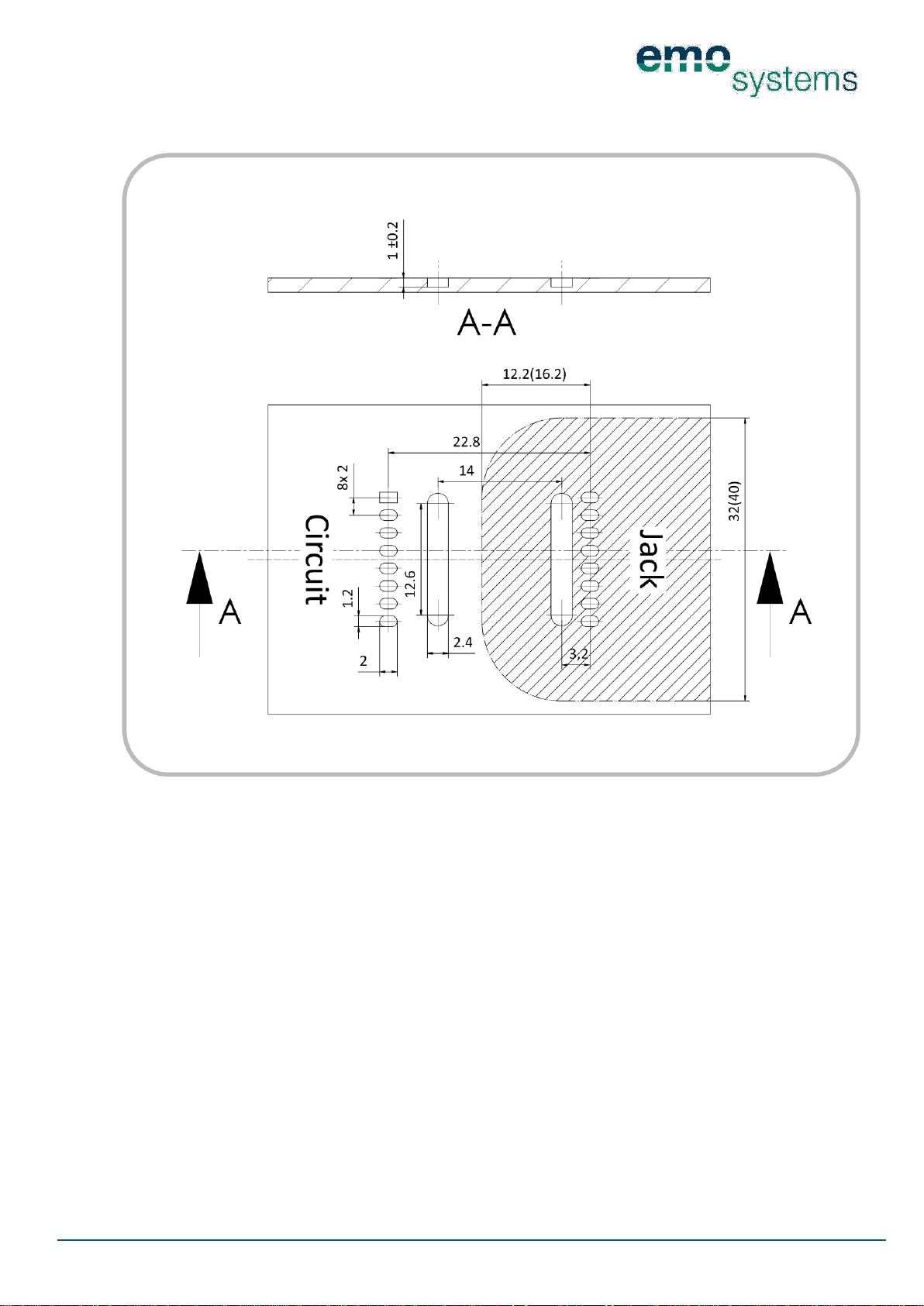
5.3.3 EN-100S PCB LAYOUT
No conductors should be placed in the shaded area as this reduces the leakage distance to inadmissible
values. The dimensions given for the shaded area refer to the requirements for the provision of two protective measures for patient protection for devices with a voltage rating of 250 V (400 V). However, the
actual requirements for the clearance and leakage distance vary, and have to be determined and checked
depending on the device. The assembly of the Network Isolators in a manner that satisfies requirements
and the relevant standards is the responsibility of the device manufacturer.
Page 13
PD 1056-V20
Page 13/23
© 2013 EMO Systems GmbH
EMO Systems GmbH • Rungestr. 19 • 10179 Berlin • Germany • Tel.: +49. 30. 4000 475-80 • Fax: +49. 30. 4000 475-90 • [email protected] • www.emosystems.de
5.4 EN-100C
5.4.1 EN-100C MODULE DIMENSIONS
Page 14
PD 1056-V20
Page 14/23
© 2013 EMO Systems GmbH
EMO Systems GmbH • Rungestr. 19 • 10179 Berlin • Germany • Tel.: +49. 30. 4000 475-80 • Fax: +49. 30. 4000 475-90 • [email protected] • www.emosystems.de
5.4.2 EN-100C FITTING DIMENSIONS
Page 15
PD 1056-V20
Page 15/23
© 2013 EMO Systems GmbH
EMO Systems GmbH • Rungestr. 19 • 10179 Berlin • Germany • Tel.: +49. 30. 4000 475-80 • Fax: +49. 30. 4000 475-90 • [email protected] • www.emosystems.de
5.4.3 EN-100C PCB LAYOUT
No conductors should be placed in the shaded area as this reduces the leakage distance to inadmissible
values. The dimensions given for the shaded area refer to the requirements for the provision of two protective measures for patient protection for devices with a voltage rating of 250 V (400 V). However, the
actual requirements for the clearance and leakage distance vary, and have to be determined and checked
depending on the device. The assembly of the Network Isolators in a manner that satisfies requirements
and the relevant standards is the responsibility of the device manufacturer.
6 HANDLING NOTES
The EN-100 model Network Isolators are for manual soldering. Procedures using a reflow oven or using
wave soldering are not allowed as this may cause thermal damage to the potting material within the
transformer component. Avoid temperatures of more than 85°C to prevent thermal stress to the transformer component.
Page 16

PD 1056-V20
Page 16/23
© 2013 EMO Systems GmbH
EMO Systems GmbH • Rungestr. 19 • 10179 Berlin • Germany • Tel.: +49. 30. 4000 475-80 • Fax: +49. 30. 4000 475-90 • [email protected] • www.emosystems.de
7 INSTRUCTIONS FOR USE
The EN-100 Network Isolator has been designed for data transmission in the frequency range of 0.3 to
100 MHz. Lower frequencies are strongly attenuated. For this reason, it is generally not possible to transmit the signals from nurse call systems, telephone systems or analogue audio or video signals over a Network Isolator.
The EN-100 Network Isolator can be used in a Power over Ethernet (PoE) network without restriction
(however PoE devices downstream of the galvanic separation cannot be supplied with power).
8 SAFETY NOTICE
8.1 SAFETY INSPECTIONS
The test interval, as well as the requirements to be met for both regular safety inspections and post-repair
inspections will then be specified for the interface to be protected by the organisation responsible based
upon the applicable standards for this system.
8.2 CLEARANCE AND LEAKAGE DISTANCES
The PCB layout and device design of devices that use the EN-100 are to be done such that the applicable
standards (e.g. IEC60601-1) for the required clearance and leakage distances are maintained.
Page 17
PD 1056-V20
Page 17/23
© 2013 EMO Systems GmbH
EMO Systems GmbH • Rungestr. 19 • 10179 Berlin • Germany • Tel.: +49. 30. 4000 475-80 • Fax: +49. 30. 4000 475-90 • [email protected] • www.emosystems.de
Category
Standards specifications or
test criteria
Characteristic
Name
EMOSAFE EN-100 (...)
Designed for
PCB module
Supported network protocols
IEEE802.3
10BaseT (Cl.14), 100BaseTx (Cl.25),
1000BaseT (Cl.40)
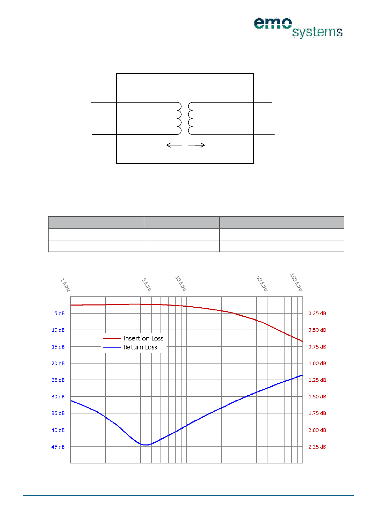
Insertion Loss
1 MHz < f < 100 MHz
<1 dB
Return Loss
1 MHz < f < 100 MHz
>14 dB
Suitable for the protection of
Ethernet interfaces in ME (medical
electrical) devices
IEC 60601-1:2005 (3rd)
UL 60601-1
Protection Class I and Class II devices or
devices with an independent power supply;
with applied parts B, BF and CF
Isolation type
Reinforced isolation
Isolation distances which are
realised internally
12.5 mm clearance and leakage distances
Markings
CE, UL, RoHS compliant, lead(Pb)-free
Category
Standards specifications or
test criteria
Characteristic
Housing dimensions
See dimensioned drawings
Weight
approx. 6 g
Category
Standards specifications or
test criteria
Characteristic
Maximum operating voltage
(maximum mains voltage) of
connected devices
IEC 60601-1:2005 (3rd)
UL 60601
≤ 400 V AC / ≤ 450 V DC
Dielectric strength (AC/DC)
AC: 4600 V / 50 Hz / 60s
DC: 8500 V / 60s
Total leakage current
275 V
AC
/ 50 Hz
12.5 µA ± 25%
Coupling capacitance
275 VAC / 50 Hz
37.5 pF / channel ±25 % (150 pF total)
Protection against momentary
transient voltages
Line to line
TVS diode circuitry
Maximum pulse power
P
pk /
tp=8/20 µs
300 W
Reverse blocking voltage
V
RWM
5 V
Terminal voltages
IPP = 1A, tp=8/20µs
12.5 V
IPP = 5A, tp=8/20µs
17.5 V
IPP = 12A, tp=8/20µs
25.0 V
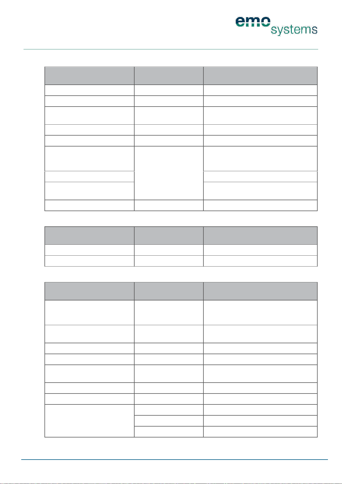
9 SPECIFICATIONS
9.1 GENERAL
9.2 MECHANICAL
9.3 ELECTRICAL
Page 18
PD 1056-V20
Page 18/23
© 2013 EMO Systems GmbH
EMO Systems GmbH • Rungestr. 19 • 10179 Berlin • Germany • Tel.: +49. 30. 4000 475-80 • Fax: +49. 30. 4000 475-90 • [email protected] • www.emosystems.de
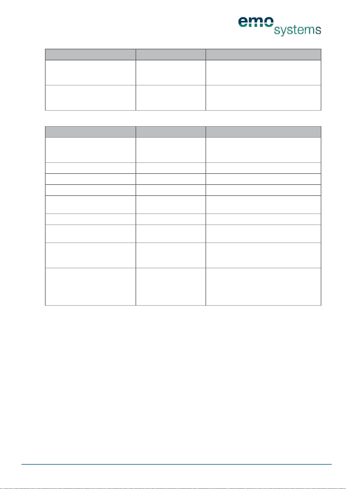
Category
Criteria
Characteristic
Storage
Temperature
Air humidity
Air pressure
-25 to +70 °C
10 to 90% (non-condensing)
700 to 1060 hPa
Transportation
Temperature
Air humidity
Air pressure
-40 to +70 °C
10 to 90% (non-condensing)
500 to 1060 hPa
Category
Characteristic
Explanatory notes
Degree of contamination
2
Contamination only arises through nonconductive materials. Occasional conductivity
caused by condensation can be expected
Excess voltage category
III
Environments with up to three-phase wiring
Maximum altitude above sea level
3200 m
Temperature
-10 to +70 °C
Air humidity
10 to 90% (non-
condensing)
Air pressure
500 to 1060 hPa
Max. operating voltage of equipment connected in V AC/V DC
400/565
Achievable protective measures,
number and type in accordance
with IEC 60601-1:2005
2 MOPP
MOOP: Means of Operator Protection
MOPP: Means of Patient Protection
Insulating material group
(CTI value)
IIIb
(100-175)
Insulating Material Group I CTI > 600
Insulating Material Group II 400 < CTI < 600
Insulating Material Group IIIa 175 < CTI < 400
Insulating Material Group IIIb 100 < CTI < 175
9.4 ENVIRONMENTAL CONDITIONS — STORAGE AND TRANSPORTATION
9.5 OPERATING CONDITIONS AND AREA OF APPLICATION
Page 19
PD 1056-V20
Page 19/23
© 2013 EMO Systems GmbH
EMO Systems GmbH • Rungestr. 19 • 10179 Berlin • Germany • Tel.: +49. 30. 4000 475-80 • Fax: +49. 30. 4000 475-90 • [email protected] • www.emosystems.de
Required
Actual dimensions
Clearance distance
7 mm
12.5 mm
Leakage distance
12 mm
12.5 mm
A
Ethernet
Ethernet
Output
PCB
9.6 ISOLATION DIAGRAM
Valid for all variants
Input
The required clearance and leakage distances in Area A of the isolation diagram result, according to IEC
60601-1, in each case from the most unfavourable permitted operational conditions; also see 9.5 OPER-
ATING CONDITIONS AND AREA OF APPLICATION.
9.7 FREQUENCY RESPONSE
Typical frequency response for the Insertion Loss and the return loss of an EN-100C Network Isolator.
Page 20
PD 1056-V20
Page 20/23
© 2013 EMO Systems GmbH
EMO Systems GmbH • Rungestr. 19 • 10179 Berlin • Germany • Tel.: +49. 30. 4000 475-80 • Fax: +49. 30. 4000 475-90 • [email protected] • www.emosystems.de
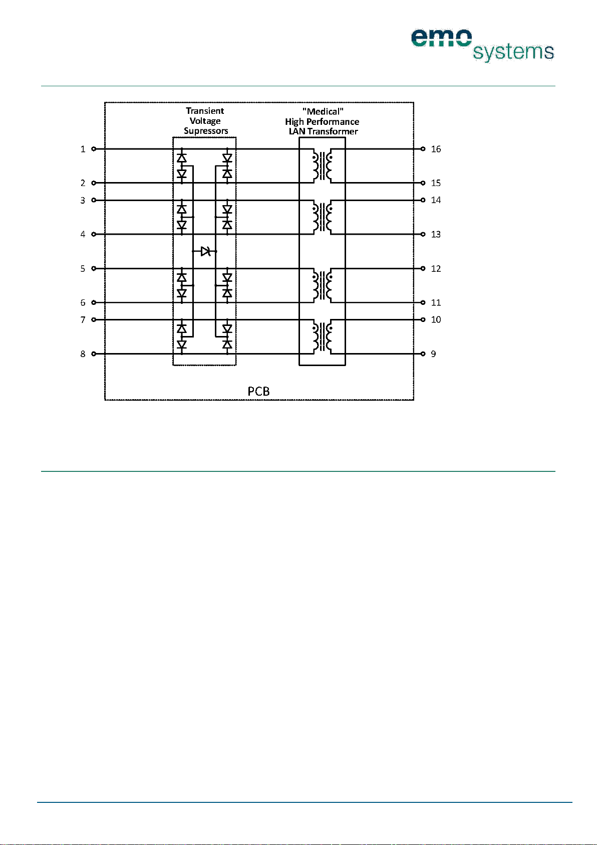
10 CIRCUIT DIAGRAM
Circuit diagram for all EN-100 variants
11 PACKAGING
Packaging contents:
EN-100 Network Isolator
A packaging label is affixed to the packaging. This label contains the following information:
Article description
Quantity
Order Code (OC)
Date of Manufacture
Serial number
The serial number is printed as a 1D- (Code 128) and 2D barcode (Data Matrix).
Page 21
PD 1056-V20
Page 21/23
© 2013 EMO Systems GmbH
EMO Systems GmbH • Rungestr. 19 • 10179 Berlin • Germany • Tel.: +49. 30. 4000 475-80 • Fax: +49. 30. 4000 475-90 • [email protected] • www.emosystems.de
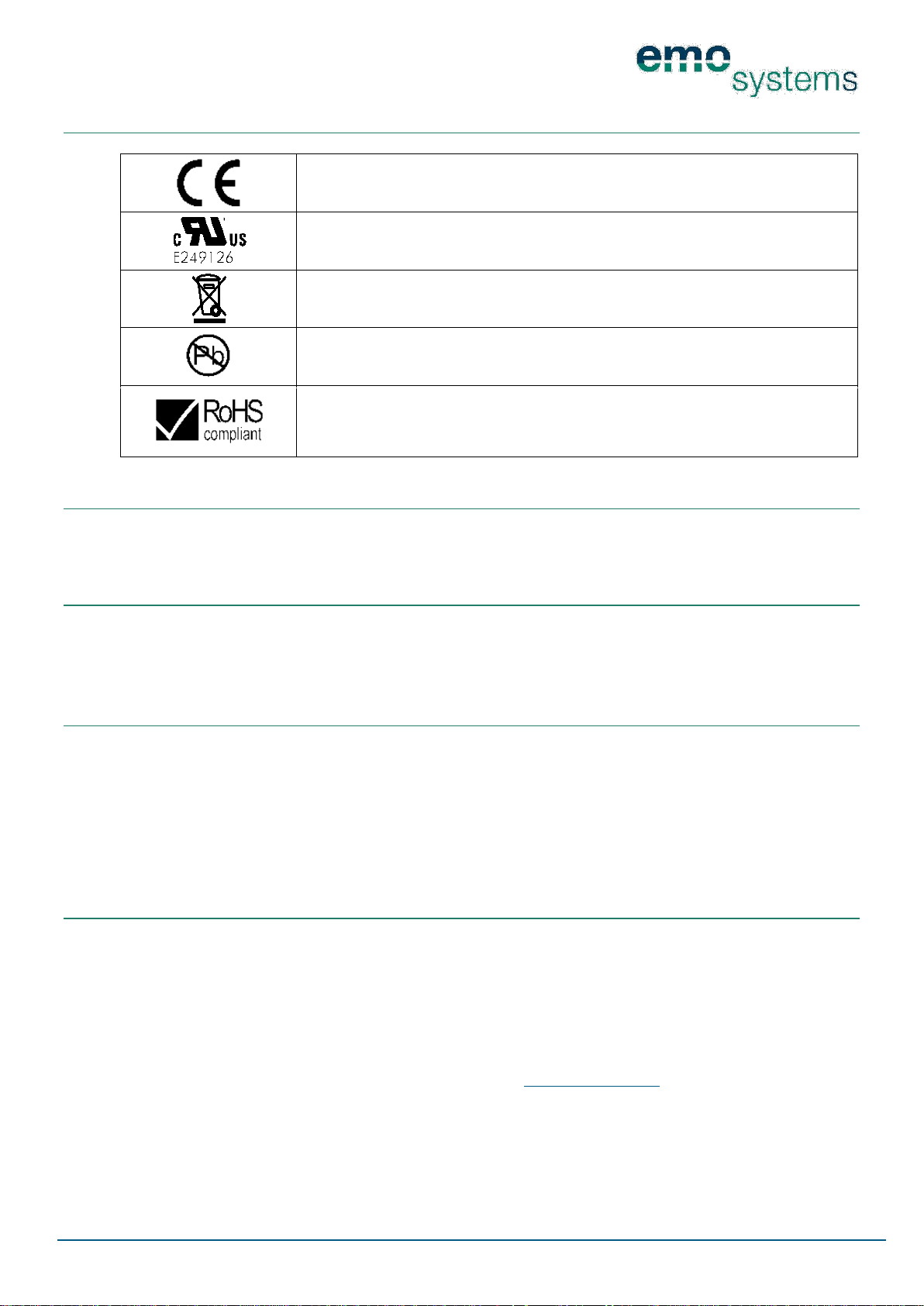
This mark certifies conformity of the product with all applicable EU Directives.
Designates the product as a UL "Recognised Component"; File no. E249126
The product may not be disposed of with domestic waste.
This product contains no substances containing lead and is manufactured using leadfree solder.
This product meets the requirements of EC Directive 2002/95/EC concerning the limitation of the use of certain hazardous substances in electrical and electronic equipment.
12 PRODUCT MARKINGS
13 MAINTENANCE
When used as directed, EMOSAFE Network Isolators are maintenance-free.
14 ENVIRONMENTAL PROTECTION INFORMATION
This device contains electronic components. At the end of its service life, it is to be returned to the manufacturer for disposal.
15 QUALITY
EMO Systems maintains a certified quality management system for development and manufacturing according to ISO 9001 and ISO 13485. Before dispatch, each Network Isolator is subjected to a comprehensive quality inspection. Among other things, an examination takes place to see whether the values
achieved for leakage current, dielectric strength, Insertion Loss, Return Loss and near-end crosstalk
(NEXT) meet the specified requirements.
16 CERTIFICATES
All Network Isolators from EMO Systems GmbH are also registered by UL International as "Recognized
Components" under the file numbers E249126 and E362969. They are therefore suitable for use in American and Canadian markets.
Furthermore, the compliance of our Network Isolators with the standards specifications IEC 60601-1:2005
(3rd Ed.), UL 60601 and CSA 22.2 no. 601.1-M90 has been confirmed by an independent, accredited laboratory. To view a copy of these certificates, please visit the UL Online Directory or contact us directly.
The conformity of our products with the requirements of the IEC 60601-1-2 is also attested to by an external laboratory. The test report is available upon request.
Page 22
PD 1056-V20
Page 22/23
© 2013 EMO Systems GmbH
EMO Systems GmbH • Rungestr. 19 • 10179 Berlin • Germany • Tel.: +49. 30. 4000 475-80 • Fax: +49. 30. 4000 475-90 • [email protected] • www.emosystems.de
Berlin, 2013-11-11
Location, Date
Friedrich Riemeier (Managing Director)
Name (Function)
17 DECLARATION OF CONFORMITY
The company
EMO Systems GmbH
Rungestraße 19
10179 Berlin
Germany
hereby declares on its sole authority that the products
EMOSAFE Network Isolators
EN-100T
EN-100L
EN-100C
EN-100S
meet the requirements of the applicable Directives 2006/95/EEC (Electrical equipment designed for use
within certain voltage limits), 2004/108/EEC (electromagnetic compatibility) and 2011/65/EU (on the re-
striction of the use of certain hazardous substances in electrical and electronic equipment).
Applied harmonised standards specifications, national standards specifications and other standards documents:
IEC 60601-1:1988, A1:1991 and A2:1995
IEC 60601-1: 2005 (3rd Edition)
IEC 60601-1-2:2007
This document is valid from
11 November 2013
Page 23

PD 1056-V20
Page 23/23
© 2013 EMO Systems GmbH
EMO Systems GmbH • Rungestr. 19 • 10179 Berlin • Germany • Tel.: +49. 30. 4000 475-80 • Fax: +49. 30. 4000 475-90 • [email protected] • www.emosystems.de
18 CONTACT AND SUPPORT
Our latest contact details can be found on our website:
http://www.emosystems.de/en/kontakt.
Alternatively, you may send an e-mail to the following address:
19 LEGAL NOTICE
The information provided has been compiled with all due care, and is believed to be accurate and reliable.
However, we cannot guarantee that the information is completely free from error.
The end user is responsible and liable for the proper use of this product; we assume no liability. We reserve the right to make changes to this data sheet without prior notice.
 Loading...