

Page 1

SWITCHMAN-3
USER MANUAL
Version 3.5
Page 2

1. Product Brief
The SwitchMan-3 system is a switching control center. The complete system
consists of the Main Unit and a wired Remote. All user controls and displays are on
the Remote. The Remote draws power from the Main Unit. The following list
summarizes features of this product:
• 4 sets of 6-channel inputs:
2 balanced/unbalanced inputs with XLR connectors
one balanced/unbalanced input with XLR and RCA connectors
one unbalanced input, RCA only
• 6-channel output with two connector sets: balanced (XLR) and unbalanced
(RCA)
• Proprietary, fully electronic volume control system
• Individual level trim and mute functions on all channels, all input s
• Templates store the system set-up data
• 115/230V 50/60Hz operating voltage
.
The signal path is made of six electrically identical channels. The gain and noise
characteristics are:
• Maximum gain (balanced IN to balanced OUT) 9 dB
• Gain control range
• Max. output level 26 dBu
• Max. input level 22 dBu
• S/N (U
• THD (U
• Crosstalk
out = 2V RMS, A-weighted) > 110 dB
out = 2V RMS) < 0.01%
better than 62 dB
better than -80 dB
2
Page 3
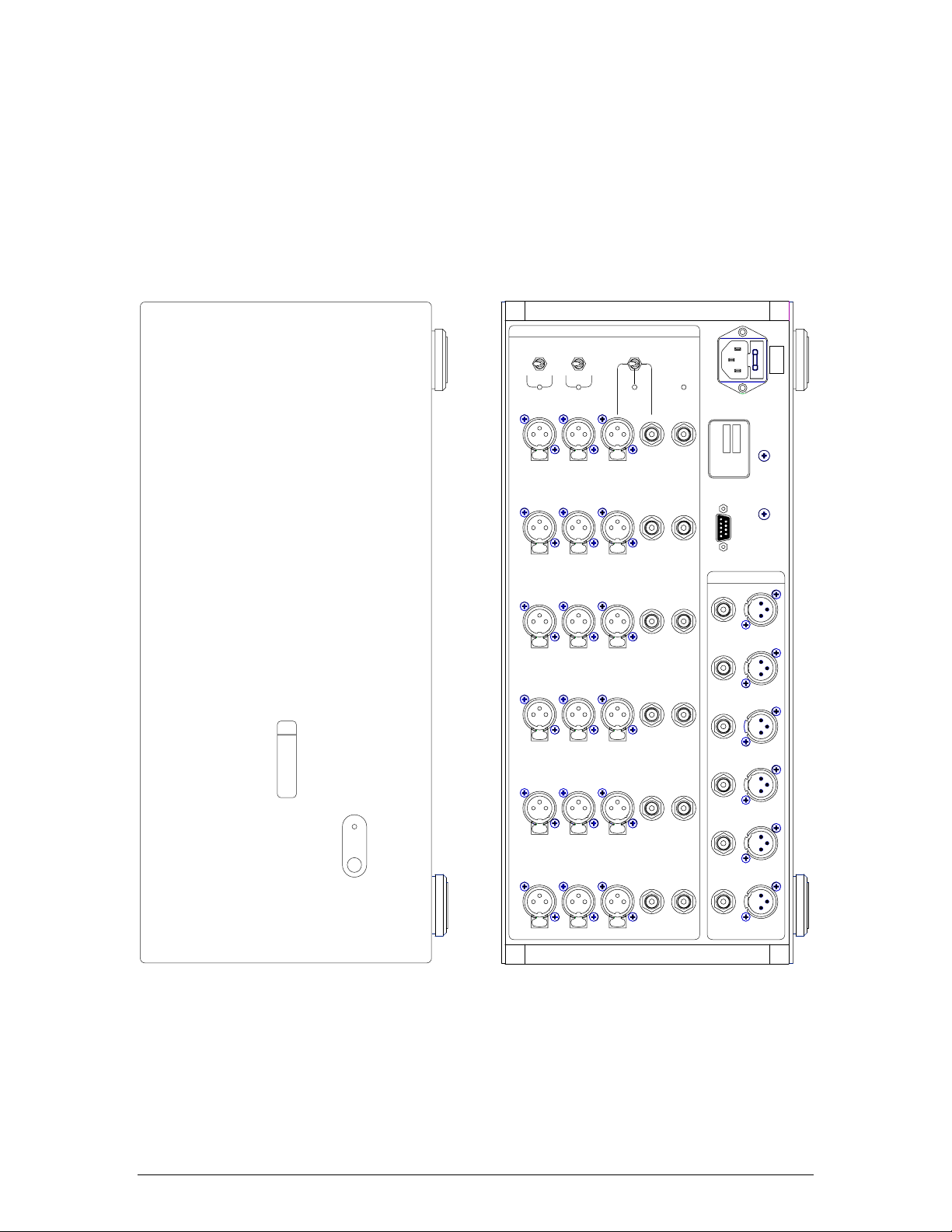
I
T
S
P
U
N
BAL
SYS A
UNBAL
BAL
SYS B
PUSH PUSHPUSH
UNBAL
SYS C
SYS D
45 VA 50 / 60 Hz
SWM-3
emmLabs
MODEL
5000
SERIAL
MADE IN CANADA
115 V
SET FOR
INTERNALLY
SWM3
meitnerdesign
Labs
emm
CH 1 CH 2 CH 3 CH 4 CH 5 CH 6
PUSH PUSHPUSH
PUSH PUSHPUSH
PUSH PUSHPUSH
PUSH PUSHPUSH
PUSH PUSHPUSH
REMOTE
T
T
S
P
U
U
O
CH 1 CH 2 CH 3 CH 4 CH 5 CH 6
3
Page 4

2. Getting Started
Caution Before turning this unit on, you MUST verify that the
system is set for the correct AC Mains voltage in your
area. The factory set voltage is indicated on the back of
the unit.
1.1 Quick Set-up
Main Unit has one port dedicated to the connection with the Remote. Look for
DB-9 modular connectors on the back panels of both units. The Remote is powered
from the Main Unit.
Typical set-up procedure will consist of the following steps:
- connect the Remote to the Main Unit using the cable provided, secure the
connectors in place
- connect audio systems to the Main Unit
- power up SwitchMan Main Unit.
The Remote-to-Main cable is terminated with DB-9 plugs: male connector on the
Main Unit side and female connector on the Remote side. Please note that DB-9
terminated cables are commonly used to connect RS-232 peripheral devices to
personal computers. On a personal computer, those DB-9 connectors are marked as
COM ports. SwitchMan’s Remote Unit is NOT an RS-232 compatible device, thus
never connect SwitchMan Remotes to COM ports on personal computers,
never connect SwitchMan Main Units to COM ports on personal computers.
After first-time power-up, the Remote should present the following information:
- Master Volume setting of 20 on the numerical display
- input system indicator LED (green) should be lit at System A
- all other LED indicators should be turned off.
The system A selector (green LED) on the Main Unit’s front panel should be lit as
well. At this point, the SwitchMan-3 is ready for operation . Turning the main knob at
the center of the Remote adjusts the Master Volume. The volume setting is displayed
as a step number ranging from 0 (“zero”, full attenuation) to 110 (max. volume).
The initial configuration of the system is as follows:
- Input System A is selected
- Master Volume level is step no. 20 (all Input Systems)
- Channel Trim value is 0 (all channels, all Input Systems)
4
Page 5

- none of the channels is mute (all Input Systems)
SwitchMan-3 uses a nonvolatile memory (NVRAM) to store Template files. A template
is a data file that saves system settings. The NVRAM contains six templates. In a
new system,
all templates are initialized to default values, as listed above.
1.2 Operation
From a user standpoint, the SwitchMan-3 system operates in three fundamental
modes:
- Volume Control Mode
- Channel Trim Mode
Template Load/Save Mode.
-
After power-up, the system always switches to the Volu me Control Mode. This is the
fundamental operational mode.
SwitchMan Quartet is operated from a Remote Unit. The top panel of the Remote has
14 buttons, 1 rotary knob, 14 LED indicators, and a numerical display. In addition,
there are two buttons on the back: SHIFT (black) and Remote RESET (red.)
1.2.1 Volume Control Mode
The system offers several functions in the Volume Control Mode:
- Master Volume Adjustment using the rotary knob at the center of the Remote
- Input Selection using buttons A, B, C, and D, on the left side of the Remote
- System Mute (all channels) using MUTE button
- channel setting inspection, using channel buttons 1, 2, 3, 4, 5, and 6 on the
right side of the Remote
- switching to the Channel Trim Mode using TRIM button
- Template Load or Template Save using LOAD/SAVE buttons.
The volume setting is displayed as a step number ranging from 0 (“zero”, full
attenuation) to 110 (max. volume.)
Fast-blinking MUTE LED indicator (red) confirms that Mute function is engaged i.e.
all channels are at full attenuation. The main knob remains active, however, and the
display is being updated. Upon disengaging the Mute, the system returns to volume
setting as shown on the display.
Green LED indicator confirms Input System selection.
Yellow LED indicator confirms the Channel selection. The Channel Settings are
presented as follows:
- Level Trim value is shown on the numerical display
- channel mute status is indicated by red MUTE LED.
Channel Level Trim is displayed as a step number ranging from –40 to +40. Trim step
equates to 0.25
the trim value of zero is displayed with a plus.
dB. Trim settings are always displayed with a plus or minus sign;
5
Page 6

In Volume Control Mode no changes can be made to channel settings - when a
channel button is pressed, the settings are viewed only. If no other buttons are
pressed at this time, the system will wait 4 seconds, then restore the main display
(Master Volume step shown again) and turn off the channel LED indicator.
To modify a channel setting, please switch to the Trim Mode first.
1.2.2 Channel Trim Mode
The Trim Mode enables modifications to channel Level Trim and ch annel Mute status.
Pressing TRIM button switches to Channel Trim Mode. To go back to Volume Control
Mode, press the TRIM button again.
In this mode, one channel is always selected; thus, one of the channel LEDs (yellow)
is lit. To operate on another channel, press the proper channel button on right side of
the Remote.
Adjust the Channel Level Trim using the rotary knob at the center of the Remote.
Channel mute status is toggled with the MUTE button.
Maximum range of channel Volume Trim is –40 to +40 steps. Trim step equates to
0.25 dB. The display always shows Trim settings with a leading sign. Th e trim value
of zero is displayed with a plus.
Please note that the system may limit the range of a trim adjustment on the plus
side. This happens if a relatively high Master Volume setting is combined with the
positive trim value. The resulting channel gain setting may be outside the system’s
range. The SwitchMan system always tracks trim values on all channels.
The “Special Features” chapter contains more information on this topic.
1.2.3 Template Load Mode
Template Load mode allows for selection of a one of six templates stored in the
NVRAM. When a template is loaded, all the settings saved in it are applied
immediately. A Template holds the following information:
- an Input System that was selected (A, B, C, or D)
- all the settings for each Input System:
- Master Volume setting
- Level Trim value for each channel (1 to 6)
- Mute Status for each channel (1 to 6)
In addition, the system “remembers” which template was loaded or saved last time.
Upon power-up, the system settings are restored because that template loads
automatically.
6
Page 7

Press TMPL button to switch to Template Mode – a yellow LED indicator above the
button should be lit. At this point you can return to Volume C ontrol Mode (press
TMPL again) or select a template using buttons 1 to 6 on the right side of the
Remote. Channel buttons double as template selectors. The Syst em will wait for a
template selection for approx. 4 seconds. If a selector key is not pressed during that
time, the SwitchMan will return to Volume Control mode.
At this point, one of the LED indicators (1 to 6) is blin king to remind you of the most
recently loaded template. Once a new template is selected, the correspondin g LED
indicator will light up. The LEDs will stay on for approx. 2 seconds and the system
returns to Volume Control Mode automatically.
New template settings are effective immediately; the Input System selector LED and
master volume display are updated.
The main rotary knob and TRIM button are inactive during template load operations.
1.2.4 Template Save Mode
Current system settings can be saved in a template. A template contains separate
data records for each Input System.
Press SAVE button to switch to Template Save Mode. Alternatively, press TMPL and
then SAVE keys to go to Template Save Mode.
Yellow LED indicators above TMPL and SAVE buttons should be lit. At this point you
can return to Volume Control Mode (press SAVE again) or select a template using
buttons 1 to 6 on the right side of the Remote. The System will wait for a template
selection for approx. 4 seconds. If a selector key is not pressed during that time, the
SwitchMan will return to Volume Control mode.
One of the LED indicators (1 to 6) blinks to remind of the most recently accessed
template.
When a template selector key is pressed, the corresponding LED indicator will light
up and the SAVE indicator will blink briefly to confirm the template save operation.
At this point, the current settings are already saved in the selected template in
NVRAM. Then SwitchMan system automatically returns to the Volume Control Mode.
The main rotary knob and TRIM button are inactive during template save
operations.
7
Page 8

3. Special Features
3.1 Channel Solo
Channel Solo, when engaged, temporarily mutes all but one selected channel.
The Channel Solo is being engaged from Volume Control Mode. Press the SHIFT
(black) key on the back of the Remote, and then one of the channel buttons 1 to 6.
The LED indicator for the selected channel will blink. T his channel stays on.
Press another channel button (without the SHIFT) to move the SOLO to the other
channel. In order to return to Volume Control Mode, press the SOLOed channel
button again. Pressing any of the input selector buttons also returns the system to
Volume Control Mode.
SOLO does not affect main knob functions – the master volume is still adjustable.
If a channel were muted, it would not be soloed - it would remain muted. The MUTE
LED shall light up to indicate mute status.
The Solo feature allows for an immediate transfer to Channel Trim M ode (press the
TRIM button now) where mute status of the channel can be changed.
3.4 Template Erase
Caution: This procedure will erase data of ALL six templates in NVRAM.
Erased template data cannot be recovered.
All templates will be reset to factory settings.
To erase Templates, follow this procedure:
- press TMPL button, the TMPL LED indicator will light u p
- press SHIFT-MUTE button; at this point, the NVRAM is being erased; all
template LED indicators (1 to 6) blink fast.
After approx. 3 seconds, the system goes through complete hardware reset (both
Main and Remote units.) During a reset phase, all templates are re-initialized with
factory settings – check default values listed in 1.1.
In practice, the Template Erase feature can be useful when the SwitchMan system is
moved to different application area. It might be more convenient to start with
known and neutral system settings rather than go through many check/modify
operations.
8
Page 9

4. Hints and Tips
• Selecting another input (A to D), or reselecting the current input again,
immediately puts the system into Volume Control Mode, thus escaping any other
mode the system is currently in.
• When inspecting settings of a given channel, you may choose to adjust that
channel right away. Press the TRIM button at this point - the channel selection
stays the same, but now the system is in Channel Trim Mode.
• The RESET (red) button on the back of the Remote Unit restarts the Remote
only; however, the system returns to Volume Control mode at this point.
• The Remote Unit can be unplugged and plugged-in at any time. You may use this
as a sure-fire variant of System Lock feature.
Set up and adjust your system, then disconnect and hide away the Remote.
When the Remote is re-connected again, the display and LED indicators shall
update immediately. Pressing the RESET button on the back of the Remote
ensures that both units are synchronized.
• If you save the current settings (in a template of your choice,) your system setup survives power-down/power-up events.
9
Page 10

Warranty
EMM Labs warrants the SWM-3 product against defects in material and workmanship
under normal use and service for a period of time specified by the product’s serial
number from the date of first delivery to the owner. The warranty time period is 5
years limited to the original owner.
EMM Labs will pay for return shipping charges back to the owner when the product is
sent to EMM Labs within the first 90 days after purchase. Otherwise, owner will be
responsible for all shipping charges to and from EMM Labs.
For all warranty claims, a copy of the original invoice must accompany the product.
Opening the product or modifying it in any way by the owner, including but not
limited to cryogenic treatment, will void any warranty.
Please contact EMM Labs (
instructions before shipping any product to EMM Labs.
EMM Labs products are sold worldwide through authorized dealers with restricted
territories. If any EMM Labs product is purchased from non-authorized dealers or
from a dealer selling outside his / her authorized territory all warranties will be void.
support@emmlabs.com) for RMA number and shipping
10
Page 11

Appendix A
Wiring for ‘REMOTE’ DB9 connector on SWM-3 rear panel in remote
control applications via external MIDI devices
The SWM-3 can be remote controlled by either the included remote control or by
external controllers via the MIDI protocol. It is not possible to use both remote
control methods at the same time, since they both use the same connector
(REMOTE). The wiring is as follows:
External MIDI controller Direction REMOTE Connector on SWM-3
MIDI In: DIN Pin 4 (+5V Sink) Å------- MIDI Out: Pin 9 (+5V Source)
MIDI In: DIN Pin 5 (Signal Return) -------Æ MIDI Out: Pin 6 (Signal Source)
MIDI Out : DIN Pin 4 (+5V Source) -------Æ MIDI In: Pin 1 (+5V Sink)
MIDI Out: DIN Pin 5 (Signal Source) Å------- MIDI In: Pin 7 (Signal Return)
The remaining pins on the REMOTE connector should not be used:
Pin 2: not connected
Pin 3: GND
Pin 4: not connected
Pin 5: GND
Pin 8: DO NOT USE (12V power supply)
Note: The DB9 pin number sequence of the REMOTE connector is that which is visible
(with a magnifying glass) on the face view of the Female DB9 connector.
5 4 3 2 1
O O O O O
O O O O
9 8 7 6
11
 Loading...