

Page 1
Version 1.1
001
PRE2 STEREO PREAMPLIFIER OWNER’S MANUAL
© 2014 EMM Labs Inc., All Rights Reserved. EMM Labs reserves the right to amend specifications & design without notice.
Page 2

Welcome
002
PRE2 STEREO PREAMPLIFIER OWNER’S MANUAL
© 2014 EMM Labs Inc., All Rights Reserved. EMM Labs reserves the right to amend specifications & design without notice.
ank you for choosing EMM Labs...
Page 3

Table Of Contents
003
PRE2 STEREO PREAMPLIFIER OWNER’S MANUAL
Welcome
Warranty
PRE2 STEREO PREAMPLIFIER
Features & Specifications
Front Panel & Functions
Rear Panel & Functions
Operational Features
Main Screen
002
005
006
007
008
008
009
011
Volume Knob and Signal Gain
Input Selectors
Product Power Up
Programming Menu
Display Contrast and Brightness
© 2014 EMM Labs Inc., All Rights Reserved. EMM Labs reserves the right to amend specifications & design without notice.
012
012
012
013
014
Page 4

Table Of Contents
004
PRE2 STEREO PREAMPLIFIER OWNER’S MANUAL
Input Naming Menu
Volume Display Units
System Maintenance
Set Volume Font
Input Preselect
Clear Settings
Infrared Remote Control
Appendix A - Serial Remote Control (RS232)
014
015
016
016
017
008
017
018
019
© 2014 EMM Labs Inc., All Rights Reserved. EMM Labs reserves the right to amend specifications & design without notice.
Page 5

Warranty
Warranty
EMM Labs warrants the PRE2 product against defects in material
and workmanship under normal use and service for a period of time
specied by the product’s serial number from the date of rst
delivery to the owner. e warranty time period is 5 years. Warranty
is limited to the original owner and is non-transferable.
EMM Labs will pay for return shipping charges back to the owner
when the product is sent to EMM Labs within the rst 90 days aer
purchase (US and Canada end-users only). Otherwise, owner will be
responsible for all shipping charges to and from EMM Labs.
005
PRE2 STEREO PREAMPLIFIER OWNER’S MANUAL
For all warranty claims, a copy of the original invoice must
accompany the product.
Opening the product or modifying it in any way by the owner,
including but not limited to cryogenic treatment, will void any
warranty.
Please contact EMM Labs (support@emmlabs.com) for RMA number
and shipping instructions before shipping any product to EMM Labs.
EMM Labs products are sold worldwide through authorized dealers
with restricted territories. EMM Labs product purchased from
non-authorized dealers or from a dealer selling outside his / her
authorized territory will automatically void product warranty.
© 2014 EMM Labs Inc., All Rights Reserved. EMM Labs reserves the right to amend specifications & design without notice.
Page 6

PRE2 STEREO PREAMPLIFIER
PRE2 STEREO PREAMPLIFIER
Built on the heritage of the famous PA6i, the PRE2 preamplier
incorporates Ed’s latest preamplication designs coupled with ground
breaking technology.
e PRE2 STEREO PREAMPLIFIER features:
• 6 sets of stereo analog inputs and 1 stereo recording loop.
• 100% contactless dual-balanced discrete audio paths.
• Proprietary soware-based analog volume control.
• Exclusive aerospace-grade composite laminate circuit boards.
006
PRE2 STEREO PREAMPLIFIER OWNER’S MANUAL
• Newly designed intuitive control system featuring
programmable input naming, settings recall and many
additional features.
• Proprietary High-isolation resonant mode power supply for
silent, green operation.
e PRE2 is the culmination of years of research and development
resulting in EMM Labs most sophisticated and transparent
preamplier to date.
© 2014 EMM Labs Inc., All Rights Reserved. EMM Labs reserves the right to amend specifications & design without notice.
Page 7

Features & Specifications
Features & Specications
S/N ratio: 110dB (A-weighted)
THD: 1kHz <0.01%; 20kHz <0.01%
Frequency range: 0Hz-100kHz
Gain control range: Better than 62dB
Maximum output level: +/- 11V p-p (+26 dBu)
Maximum input level: +/- 7V p-p (+22 dBu)
System Gain: +12dB
Analog Inputs:
• 2 Stereo sets of Balanced (XLR) - Input Impedance: 20kΩ
007
PRE2 STEREO PREAMPLIFIER OWNER’S MANUAL
• 4 Stereo sets of Un-Balanced (RCA) - Input Impedance: 10kΩ
• 1 Stereo Loop Input Un-Balanced (RCA) - Input Impedance: 50kΩ
Analog Outputs:
• 1 Stereo set of Balanced (XLR) - Output Impedance: 150Ω
• 1 Stereo set of Un-Balanced (RCA) - Output Impedance: 75Ω
• 1 Stereo Loop Output Un-Balanced (RCA) - Output Impedance: 300Ω
System:
• System control via serial RS-232
• Soware upgradeable
Power Consumption Max: 40W
Dimensions W x D x H: 435 x 400 x 92mm, Weight: 12kg
© 2014 EMM Labs Inc., All Rights Reserved. EMM Labs reserves the right to amend specifications & design without notice.
Page 8
Front Panel and Functions
Front Panel & Functions
008
PRE2 STEREO PREAMPLIFIER OWNER’S MANUAL
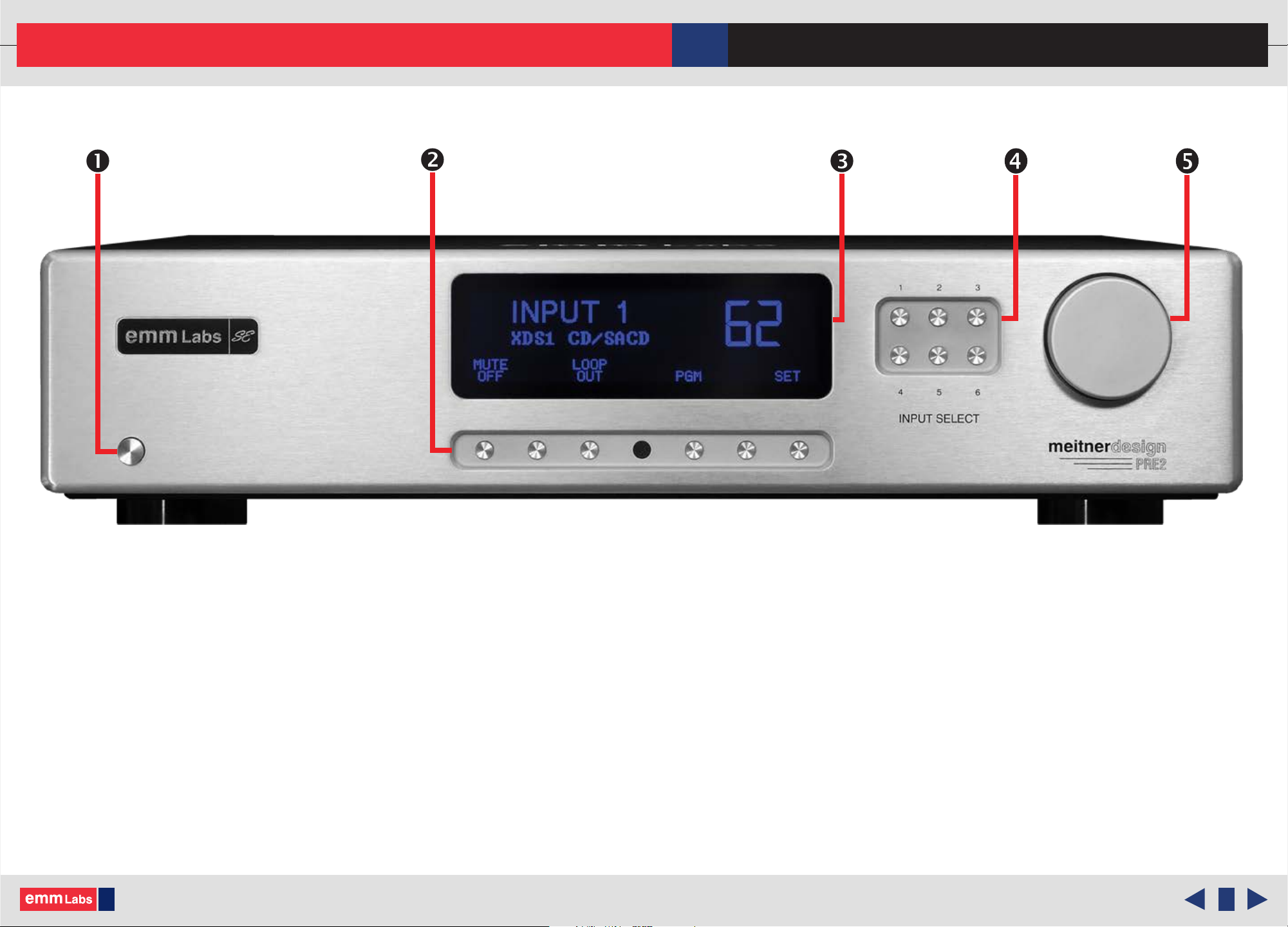
1. Standby/Power-Save button:
Toggles the operation between on and power-save mode. In power save mode the
remote control and all front panel functions become inactive.
2. Program and Function buttons:
Front panel buttons used to access functions and program the PRE2.
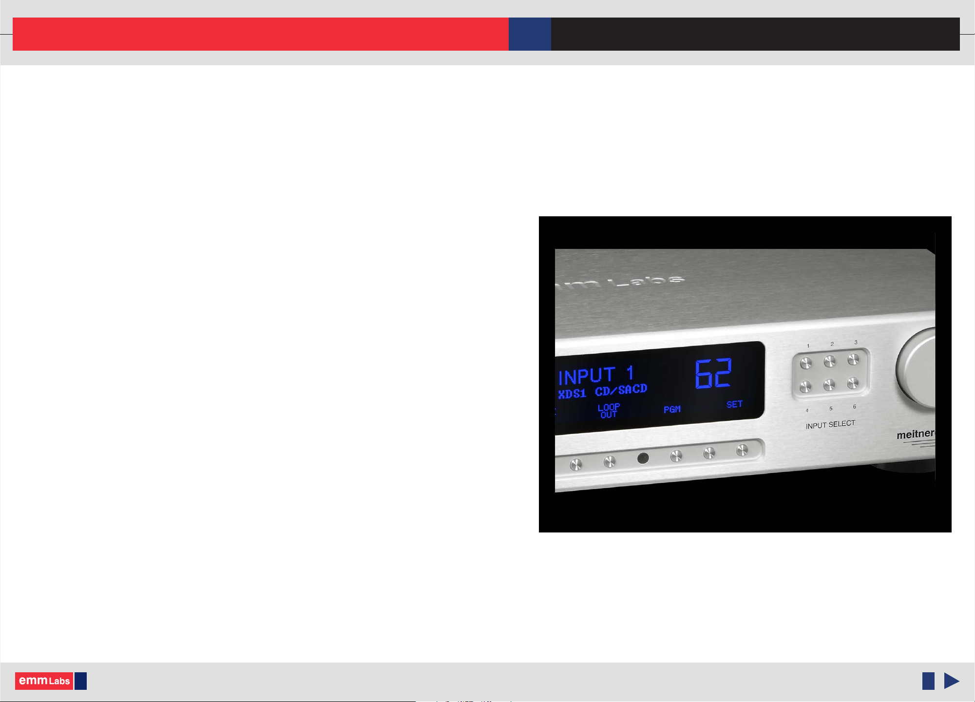
3. PRE2 Display:
Display can be dimmed or turned o using the the remote DIM button.
4. Input Selection buttons.
5. PRE2 Volume Knob.
© 2014 EMM Labs Inc., All Rights Reserved. EMM Labs reserves the right to amend specifications & design without notice.
Page 9

Back Panel and Functions
Back Panel & Functions
009
PRE2 STEREO PREAMPLIFIER OWNER’S MANUAL
1. Analog Inputs:
• Inputs 1 and 2 are balanced XLR inputs
• Inputs 3, 4, 5 and 6 are un-balanced RCA inputs
2. Loop Input and Output (un-balanced)
3. Analog Outputs:
• Le and Right Balanced (XLR) Connectors
• Le and Right Un-Balanced (RCA) Connectors
4. System:
• Remote RS232: RS232 control port
• USB: soware update port
© 2014 EMM Labs Inc., All Rights Reserved. EMM Labs reserves the right to amend specifications & design without notice.
Page 10

Back Panel and Functions
010
PRE2 STEREO PREAMPLIFIER OWNER’S MANUAL
Back Panel & Functions
4. System (Cont’d):
• RESET: Used to access the backup BIOS.
5. Product model and serial number indicator:
Warranty void if model/serial number indicator is not attached to unit, missing or
damaged whereby serial number cannot be seen.
6. Main Power connector and Power Switch
7. Product VOLTAGE indicator:
Indicates working voltage of the PRE2. Only use with indicated line voltage.
© 2014 EMM Labs Inc., All Rights Reserved. EMM Labs reserves the right to amend specifications & design without notice.
Page 11

Operational Features
Main Screen
1. Mute Button
Pressing the mute button initiates a 2-stage, sequential Mute
function. So Mute (-20dB from the current level), Full Mute,
and nally Mute O. Mute is O/disabled as soon as the
Volume knob is rotated or the Volume buttons are depressed
on the remote. Once Mute is o the PRE2 will return the
signal path to its current volume setting. A short fade-in is
performed to avoid audible transient artifacts.
2. Loop Button
011
PRE2 STEREO PREAMPLIFIER OWNER’S MANUAL
e Loop function allows for the insertion of an external
device (e.g. signal processor) into the main signal path. ere is no gain applied to loop return signal. e state of Loop path
is input-dependent. Each preamp input can engage the Loop as required.
3. PGM Button
e PGM (program) opens a pop-up menu with 4 main programming or conguration selections. New navigation buttons
will appear: Up, Down, Enter, and Exit. See “Programming Menu” section.
4. SAVE Button
e SAVE function immediately saves the state of the system in non-volatile memory. e following parameters are saved:
• Volume Step Number and Loop state - as set for each input
• Volume Display Units (steps or decibels)
• Volume Font: 7-Segment or a ‘Designer’ font
• LCD display Contrast and Brightness settings
• e default input to be selected upon power-up.
© 2014 EMM Labs Inc., All Rights Reserved. EMM Labs reserves the right to amend specifications & design without notice.
Page 12

Operational Features
012
PRE2 STEREO PREAMPLIFIER OWNER’S MANUAL
Main Screen
4. SAVE Button (cont’d)
Notes:
• e Mute is a transient feature and its state is not saved. PRE2 product powers up with Mute O.
• Input names are saved from a dedicated, on-screen name editor; see the ‘Programming Menu’
e Volume Knob and Signal Gain
e Volume knob adjusts the signal gain from full attenuation (step 0) to maximum gain at step 100. e maximum gain
measured from any input to RCA output is +6dB. e maximum gain measured from any input to XLR output is +12dB.
From the top of the control range (Step 100) down to Step 10, a single step lowers the gain by 0.5dB. Below Step 10, the
changes are progressively coarser. Step 1 is at -64dB. Volume indicator on the main screen shows either the Volume Step or
Signal Gain in decibels (Please ‘Programming Menu’ to change Volume indicator). e gain is referenced to signal level at the
RCA outputs. Actual gain at XLR outputs is 6dB higher.
Input Selectors (1 to 6)
Input selection buttons connect one of six front-end input stages to main signal path. e system performs short fadeout/
fade-in operation on signals being switched. Please Note: e Mute is applied in the main (common) signal path; input
selection does not aect the state of Mute.
Product Power-up
Upon Power-Up Reset, the system controller restores the input and display settings as listed in section 1.1.4. In addition,
all input names (kept in separate les in non-volatile memory) are restored. File data integrity is checked. Should data
corruption occur, the system reformats aected set-up les and restores default conguration.
© 2014 EMM Labs Inc., All Rights Reserved. EMM Labs reserves the right to amend specifications & design without notice.
Page 13

Operational Features
013
Product Power-up (cont’d)
In a newly built product or when PRE2 is reset, default settings are as follows:
• Selected input : Input 1 (XLR)
• Volume : Step 0 (all inputs)
• Volume Units : Steps
• Loop : O (all inputs)
• Mute : O
• LCD Contrast/Brightness : Mid-point
• Input Names: : Blank, no characters (all inputs)
• Volume Font : ‘7-segment’ font
PRE2 STEREO PREAMPLIFIER OWNER’S MANUAL
Programming Menu
In this release, the programming menu has 4 items, shown in a pop-up box on the LCD screen.
© 2014 EMM Labs Inc., All Rights Reserved. EMM Labs reserves the right to amend specifications & design without notice.
Page 14

Operational Features
Programming Menu (cont’d)
014
PRE2 STEREO PREAMPLIFIER OWNER’S MANUAL
Display Contrast and Brightness
Input Naming Menu
1. Display Contrast and Brightness
Contrast and Brightness both have a 9-step adjustment range, visualized on screen by horizontal indicator bar. e le
and right arrow so buttons operate the adjustment. Contrast and Brightness adjustments have separate screens, and the
so button ‘NEXT’ allows you to access both screens. Both settings are saved in non-volatile memory from the main
screen.
2. Input Naming Menu
Input names are edited using the Volume knob and the line editor with 3 so buttons: Cursor Le, Cursor Right, and
Backspace Erase. Rotating the Volume knob changes the character at the cursor position. e character set is as follows:
• capital letters A-Z
• SPACE character
© 2014 EMM Labs Inc., All Rights Reserved. EMM Labs reserves the right to amend specifications & design without notice.
Page 15

Operational Features
015
PRE2 STEREO PREAMPLIFIER OWNER’S MANUAL
Programming Menu
2. Input Naming Menu (cont’d)
• DASH, PERIOD, and SLASH characters
• digits 0-9.
Rotating the Volume knob scrolls through the characters. Pressing one of Input Selector buttons shows the current name
of the input, and allows the name to be edited. e name being edited is stored only by pressing the ‘SAVE’ button on this
screen. Pressing another input button or selecting a dierent/same input discards the changes. Pressing the ‘Quit’ button
returns you to the ‘Programming Menu’ page, discarding any changes made.
3. Volume Display Units
e screen shows a sample value of the Volume display.
e ‘Change Units’ so button toggles the Volume
display units to the following two options:
• Volume Step
• Gain in [dB]
e Volume knob is active and you can change the
sample value. e actual Volume (signal gain) is not
aected. e Volume display unit selected is stored only
by pressing the ‘SAVE’ button. Upon ‘EXIT’ aer ‘SAVE’
the main screen will display the selected Volume display
unit. Pressing ‘EXIT’ without pressing ‘SAVE’ discards any changes.
© 2014 EMM Labs Inc., All Rights Reserved. EMM Labs reserves the right to amend specifications & design without notice.
Page 16

Operational Features
Programming Menu
4. System Maintenance
016
PRE2 STEREO PREAMPLIFIER OWNER’S MANUAL
System Maintenance
Volume Font Selection
e System Maintenance screen shows the current rmware version and a list of maintenance tasks. e tasks are
selected by using the numbered input select buttons. In this release, there are 3 maintenance tasks:
• Set Volume Font (2 options):
a. 7-segment font
b. EMM font
In future updates EMM may update the Volume Font selection with many other fonts.
Font selection is saved only when you press the ‘SAVE’ button. Pressing ‘EXIT’ without pressing ‘SAVE’ discards any
changes.
© 2014 EMM Labs Inc., All Rights Reserved. EMM Labs reserves the right to amend specifications & design without notice.
Page 17

Operational Features
017
PRE2 STEREO PREAMPLIFIER OWNER’S MANUAL
Programming Menu
4. System Maintenance (cont’d )
• Input Preselect
e power-on input can be changed by the user using the ‘Input Preselect’ feature. e current power-on input is
shown on-screen. At this point, any Input can be chosen either by pressing the associated numbered input button or
by using the ‘NEXT’ so button. Pressing the ‘SELECT’ so button saves the new setting.
Input Preselect
Clear Settings
• Clear Settings
All user settings will be reset to run the factory default programming. An alert box ‘Proceed?’ is shown rst
allowing the user to cancel the operation.
© 2014 EMM Labs Inc., All Rights Reserved. EMM Labs reserves the right to amend specifications & design without notice.
Page 18

Infrared Remote Control
018
PRE2 STEREO PREAMPLIFIER OWNER’S MANUAL
Infrared Remote Control
VOL UNITS : is button toggles volume display units between steps and dB
DIM : is butons toggles through the 3 display states:
• DIM (dim the display)
VOL
UNITS
DIM
DISPLAY
• OFF (display o)
• FULL (back to the current default setting)
INPUT (1 to 6) : ese buttons can be used to directly access any INPUT.
LOOP : Turns LOOP funtion on/o for the selected INPUT
MUTE : is buttons toggles through 3 MUTE states:
• SOFT MUTE
• MUTE
• MUTE OFF
VOLUME : Controls the volume/signal gain. Press the up arrow button to
increase volume/gain. Press the down arrow button to decrease
LOOP
INPUT
1
4
VOLUME
2
5 6
MUTE
3
volume/gain
© 2014 EMM Labs Inc., All Rights Reserved. EMM Labs reserves the right to amend specifications & design without notice.
Page 19

Appendix A - PRE2 Serial Remote Control (RS232)
019
PRE2 STEREO PREAMPLIFIER OWNER’S MANUAL
PRE2 Serial Remote Control (RS232)
Introduction
e PRE2 can be remotely controlled in one of the two (mutually exclusive) modes:
• Standard mode
• Slave Preamp mode.
In Standard mode the product receives and acts upon the RC-6 Infra Red Remote commands. Recognized IR codes are
translated into EMM Labs’ ASCII-based control commands that are sent out on the RS232 port. e Command Protocol is
dened in Section 2. e PRE2 also receives the control commands from RS232 port. Recognized commands are acted upon,
and, in addition, echoed (sent out) in the transmit path on the RS232 port.
All outgoing RS232 commands are destined for slave PRE2s, which are meant to act in sync with main unit. In Slave Preamp
mode, the IR Remote receiver is disabled, but the product still receives commands at its RS232 port. As before, the decoded
and recognized commands are echoed in the transmit path of the RS232. is will facilitate product daisy-chaining, where
multiple slave preamps can act in sync with the main (Standard) unit.
In either mode, all front panel controls and menus are fully operational. Standard/Slave modality determines only the
IR remote control capabilities of this product. e Standard controller mode is best used in the following scenarios:
• PRE2 is the only preamp in a system
• PRE2 is the main pre-amp in a multichannel set-up, typically running front-le and front-right channels; the main
preamp is receiving IR remote commands, while other preamps are slaved to it.
e Slave mode should be used when the PRE2 is in the signal path of any additional channels in a multichannel
set-up. e slave unit follows main preamp actions while the main unit receives IR Remote commands. Multiple
slave preamps can be connected in a daisy-chain conguration.
© 2014 EMM Labs Inc., All Rights Reserved. EMM Labs reserves the right to amend specifications & design without notice.
Page 20

Appendix A - PRE2 Serial Remote Control (RS232)
PRE2 Serial Remote Control (RS232)
Remote Control Protocol
e PRE2 Remote Control protocol is dened with the goal of structural simplicity and ease of implementation. Typical
implementation requires only a standard, asynchronous UART/RS232 port. At the Data Link level the following assumptions
are made:
• Short, xed-length data frames
• Data encoding uses only ascii (printable) characters
• Data frame has a checksum eld for error detection, but the checksum opt-out is possible at sender’s request - in such a
case, Sender’s frame has a standard blank checksum, and the Receiver side does not check against it.
020
PRE2 STEREO PREAMPLIFIER OWNER’S MANUAL
At the Application level (i.e. remote control of a product) the message processing will be stateless:
• Each message is handled independently
• Each command acted upon immediately.
Frame Structure
e PRE2 frame structure is shown in the following diagram:
P1 P0 M3 M2 M1
*
Frame preamble : < > Asterisk character.
| Product Class
| Command Message
M0
C1 C0
| Cheksum |
*
Destination Product Class : P1, P0 two alphanumeric characters (a preamplier product will be denoted as "PR").
Command Message : M3, M2, M1, M0 typically 4 characters long, but it is product-dependent.
© 2014 EMM Labs Inc., All Rights Reserved. EMM Labs reserves the right to amend specifications & design without notice.
Page 21

Appendix A - PRE2 Serial Remote Control (RS232)
021
PRE2 STEREO PREAMPLIFIER OWNER’S MANUAL
PRE2 Serial Remote Control (RS232)
Frame Structure (cont’d )
Checksum : C1, C0 one-byte checksum, its binary value represented by 2 hex characters, or, <N><A> the
opt-out variant, where the checksum is substituted by "NA" token, as in 'Not-A-checksum' or
'Not Applicable'. e checksum is calculated as byte-wide exclusive OR from all preceding
characters in the frame, excluding frame preamble (the asterisk). Checksum seed value is
0x00. Character ASCII codes are used in the calculation.
Command Message Structure
e Command Message for PRE2 is four character long (M3, M2, M1, and M0) and is composed of two parts:
Command Code : C1, C2 two alphanumeric characters and/or decimal digits (A-Z, a-z, 0-9)
Parameter Value : V1, V2 one-byte value represented by 2 hex digits (0-9, A-F).
Control Messages
Complete message frames are shown, and the blank checksum (the “NA”) is used.
Volume (VL) : *PRVLxxNA where ‘xx’ is volume step number (0 to 100) formatted as 2 hexadecimal digits.
Examples: step number 10 will be encoded as ‘0A’ or step number 100 will be encoded as ‘64’.
Select Input (SI) : *PRSI0iNA where 'i' is the input number, encoded as a character '1' to '6'
Mute (MT) : *PRMT00NA mute OFF
*PRMT01NA so mute
*PRMT02NA mute ON
© 2014 EMM Labs Inc., All Rights Reserved. EMM Labs reserves the right to amend specifications & design without notice.
Page 22

Appendix A - PRE2 Serial Remote Control (RS232)
022
PRE2 STEREO PREAMPLIFIER OWNER’S MANUAL
PRE2 Serial Remote Control (RS232)
Control Messages (c ont’d)
Loop (LP) : *PRLP00NA loop OFF
*PRLP01NA loop ON
Display Dim (DM) : *PRDM00NA no dimming, full brightness
*PRDM01NA reduced brightness
*PRDM02NA the backlight is turned o
Volume Display
Units (VU) : *PRVU00NA reserved code
*PRVU01NA the Volume is displayed in Steps (0 to 100)
*PRDM02NA the gain of signal path is shown (in Decibels)
Save settings (SV) : *PRSV00NA product operational settings are saved in non-volatile memory
NULL Cmd. (NL) : *PRNLxxNA where ‘xx’ are any 2 alphanumeric characters; this message is used in system
testing only.
Control Message Timing
Back-to-back command messages can be sent to PRE2 unit, however, no ow control mechanism is used. e longest
recommended data burst is 10 messages. In such a case the burst should be followed by 100ms of idle time. In a real-life
system, this constraint is of no consequence.
© 2014 EMM Labs Inc., All Rights Reserved. EMM Labs reserves the right to amend specifications & design without notice.
Page 23

Appendix A - PRE2 Serial Remote Control (RS232)
PRE2 Serial Remote Control (RS232)
RS232 Port Set-up
e RS232 Control port in PRE2 is set up as follows:
• Baud rate 9600bps
• Character length 8 bits
• Stop Bits 1
• Parity none
Product Class Denitions
023
PRE2 STEREO PREAMPLIFIER OWNER’S MANUAL
• Disc Transport : "CD"
• SACD Player : "SC"
• Blu-ray Player : "BD"
• Preamplier : "PR"
• DAC : "DA"
• Media Player : - to be dened -
• Signal Processor : - to be dened -
• Power Amplier : - to be dened -
Note: SACD or Blu-ray players can accept generic disc transport commands ("CD"), and, in addition, their product-specic
commands. e command set for a SACD player, for example, should support the Program and Layer Selections.
© 2014 EMM Labs Inc., All Rights Reserved. EMM Labs reserves the right to amend specifications & design without notice.
Page 24

Appendix A - PRE2 Serial Remote Control (RS232)
024
PRE2 STEREO PREAMPLIFIER OWNER’S MANUAL
PRE2 Serial Remote Control (RS232)
RS232 Cables for PRE2
Standard, direct RS232 cable from a PC (or dedicated System Controller) to PRE2
DB9
FEMALE
PC or System
Controller
DB9
MALE
5
9
4
8
3
7
2
6
1
5
9
4
8
3
7
2
6
1
PRE2
SHIELD
© 2014 EMM Labs Inc., All Rights Reserved. EMM Labs reserves the right to amend specifications & design without notice.
Page 25

Appendix A - PRE2 Serial Remote Control (RS232)
PRE2 Serial Remote Control (RS232)
RS232 Cables for PRE2 (con t’d)
025
PRE2 STEREO PREAMPLIFIER OWNER’S MANUAL
Y-patchcord for PRE2 daisy chaining.
e patchcord has 2 ‘legs’:
• from PRE2 (central) connector to the
Input connector, and
• from PRE2 connector to slave Output
connector.
Recommended length is 12 to 14 inches for
each leg (approx. 30 to 35 cm).
DB9
FEMALE
PC or System
Controller
DB9
MALE
5
9
4
8
3
7
2
6
1
5
9
4
8
3
7
2
6
1
PRE2
SHIELD
DB9
MALE
5
9
4
8
3
7
2
6
1
SLAVE
PRE2
© 2014 EMM Labs Inc., All Rights Reserved. EMM Labs reserves the right to amend specifications & design without notice.
 Loading...