

Page 1

ADC8 Mk IV
DAC8 Mk IV
USER MANUAL V1.3
Page 2

A/D Converter ADC8 Mk IV
The EMM Labs 8-channel A/D converter is a 4th generation design to meet
the highest standards in professional audio recording applications. It offers
conversion between analog and digital audio of various different formats, as
well as conversion between digital audio formats.
Features
• 8-channel conversions:
• from analog to PCM (16/24 bits selectable and 44.1kHz - 96kHz)
• from analog to DSD
• from DSD to PCM (44.1kHz - 16/24 bits selectable)
• from DSD on optical to DSD on BNC connectors
• from DSD on BNC to DSD on optical connectors
• Supported output formats:
• AES/EBU (4 connectors) for PCM
• “RAW DSD” (legacy format for DSD on BNC conectors)
• SDIF-3 for DSD on BNC connectors
• SDIF-2 for PCM on BNC connectors
• ST Fiber optic for DSD
• Supported input formats:
• Balanced analog 8dbu - 32dbu (pin 2 hot), switchable ranges 8dbu-20dbu /
20dbu - 32 dbu.
• “RAW DSD” (legacy format for DSD on BNC conectors)
• SDIF-3 for DSD on BNC connectors
• ST Fiber optic for DSD
• Power supply
• power factor corrected
• auto ranging 85V - 240V, 50/60Hz
• power consumption: 60W
• Analog input impedances
• in HI gain position: 30kΩ balanced, 15kΩ unbalanced
• in LO gain position: 68kΩ balanced, 34kΩ unbalanced
1
Page 3
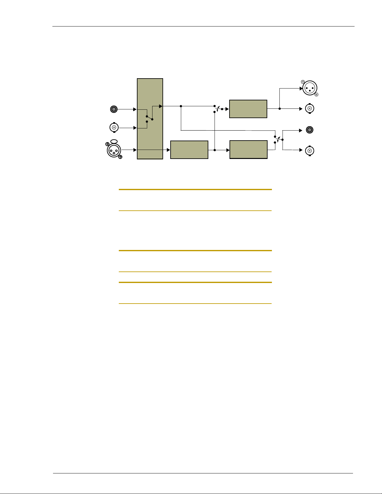
Signal flow
DSD (Optical)
DSD
DSD to PCM
Conversion
PCM
(AES/EBU)
PCM
(SDIF2)
DSD (RAW/SDIF3)
(shared Conn.)
Analog
Note: Analog inputs are balanced with pin 2 hot, pin 3 cold and pin 1 GND. For unbalanced
inputs just connect to pin 2 and tie pin 3 to GND.
Function Switches
Note: Some configurations require long settling times of up to several seconds after changing
switch positions.
Note: The powerup sequence and initial calibration of the unit takes about 20 seconds after
power is applied.
A/D
Conversion
DSD
DC Removal
DSD
(optical)
DSD
(shared Conn.)
Clock Section
INT /EXT: Selects internal or external clock source. LOCK LED is lit
OPTIC / BNC: Selects external clock between optical and BNC formats.
Sample Rate Section
64 / 128: Selects oversampling ratio. 128 position does not allow
1FS / 2FS: Selects the sample rate for PCM data. FS is the base
44.1 / 48: Selects the base frequency (only 44.1kHz is allowed for
when A/D converter is locked to external clock.
2FS PCM generation (error light on).
frequency (see 44.1 / 48 switch). 2FS position will mute
outputs when the oversampling ratio is set to 128.
DSD outputs and inputs).
2
Page 4
3
Page 5

Digital Audio Input Section
OUT / IN: OUT position selects conversion from analog to digital.
IN position selects conversion from digital to digital.
OPTIC / BNC: If the DATA DIR switch is set to IN, this selects data
input between optical or BNC connectors (data format is
selected in Interface Format Section).
Interface Format Section
RAW / SDIF-3: When DSD is on BNC the user has the choice between
RAW and SDIF-3 formats.
DSD / PCM: This switch selects DSD or PCM format on the BNC
connectors (in both directions).
OPTIC1 / OPTIC2: Selects format 1or 2 for both input and output (currently
not implemented - only 1 format).
16 / 24 BITS: The wordlength of the PCM outputs can be selected
between 16 and 24 bits. The 16 bit position uses noise
shaping to convert original format of 24 bits to 16 bits.
Error Indicator is lit for illegal switch positions (audio outputs are muted)
Analog Input Level
LO / HI: The LO position allows the user to set levels between
Clipping indicators
The clipping LED’s come on when the level on the PCM outputs reach
0dbFS. This level corresponds to 0dbSACD on all DSD outputs. However,
the levels on the DSD outputs are allowed to go up to +3dbSACD.
+20dbu and +32dbu.
The HI position allows the user to set the levels between
+8dbu and +20dbu.
4
Page 6

Table 1: Functional Modes of A/D
Conversion BNC Analog In AES/EBU Optical In Optical Out
Analog to
DSD, PCM
Analog to
DSD, PCM
DSD to DSD,
PCM
DSD to DSD,
PCM
DSD Out In PCM Out - DSD Out
PCM Out
(SDIF-2)
DSD In - PCM Out - DSD Out
DSD Out or
PCM Out
Basic Operation
In addition to the basic conversion modes shown below, the ADC8 Mk IV
converts between DSD on optical and DSD on BNC (RAW DSD or SDIF-3)
and back again.
Conversion from Analog to DSD and PCM
INT
CLOCK
OPTIC
64
SAMPLE RATE
1 FS
In PCM Out - DSD Out
- PCM Out DSD In DSD Out
44.1
OUT
OPTIC
RAW DSD
INTERFACE FORMATDIGITAL AUDIO IN
DSD
16 BIT
EXT
LOCK BNC
EXTERNAL
128
OVERS.
2 FS
PCM
48
BASE
IN
DATA-DIR
BNC
SDIF-3 PCM
2
24 BIT
PCM OUTOPTICBNC
“Empty” switches are ignored.
Note: DSD and PCM is only generated simultaneously when the base frequency 44.1kHz and
1FS are selected.
Note: The PCM sample rate of 2FS can only be selected for the oversampling ratio of 64FS
Optional selections:
• Oversampling ratio 64FS / 128FS: this changes the bit rate of the DSD
output. No optical DSD output is generated for 128FS. When 128FS is
selected DSD is generated at 128FS in either RAW DSD or SDIF-3 format.
• Wordlength of PCMOUT 16bit / 24 bit
• The PCM data can also be routed to the BNC outputs (SDIF-2 format) with
the DSD / PCM switch.
5
Page 7

• DSD format on BNC connectors RAW DSD / SDIF-3
Conversion from DSD to PCM
INT
EXT
CLOCK
LOCK BNC
EXTERNAL
OPTIC
64
128
OVERS.
SAMPLE RATE
1 FS
2 FS
PCM
44.1
48
BASE
OUT
IN
DATA-DIR
OPTIC
BNC
RAW DSD
SDIF-3 PCM
INTERFACE FORMATDIGITAL AUDIO IN
DSD
“Empty” switch positions are ignored.
DSD input can be on BNC or optical connectors. Appropriate selections have
to be made in the CLOCK and DIGITAL AUDIO IN sections (OPTIC / BNC).
DSD data rate at input can be either 64FS or 128FS as selected by
Oversampling ratio.
Note: 2FS PCM generation is only possible from 64FS DSD and not from 128FS.
Optional selections:
• Wordlength of PCMOUT 16bit / 24 bit
• The PCM data can also be routed to the BNC outputs (SDIF-2 format) with
the DSD / PCM switch, in case the DSD input is optical.
16 BIT
2
24 BIT
PCM OUTOPTICBNC
6
Page 8

D/A Converter DAC8 Mk IV
The EMM Labs 8-channel D/A converter is a 4th generation design to meet
the highest standards in professional audio recording applications. It offers
conversion between digital audio of various different formats and analog, as
well as conversion between digital audio formats.
Features
• 8-channel conversions:
• from PCM (44.1kHz - 96kHz) to analog
• from DSD to analog
• from PCM (44.1kHz, 88.2kHz) to DSD
• from DSD on optical to DSD on BNC connectors
• from DSD on BNC to DSD on optical connectors
• from PCM on AES/EBU to PCM (SDIF-2)
• Supported input formats:
• AES/EBU (4 connectors) for PCM
• “RAW DSD” (legacy format for DSD on BNC conectors)
• SDIF-3 for DSD on BNC connectors
• SDIF-2 for PCM on BNC connectors
• ST Fiber optic for DSD
• Supported output formats:
• Balanced analog 14dbu - 24dbu (pin 2 hot)
• “RAW DSD” (legacy format for DSD on BNC conectors)
• SDIF-3 for DSD on BNC connectors
• SDIF-2 for PCM on BNC connectors
• Power supply
• power factor corrected
• auto ranging 85V - 240V, 50/60Hz
• power consumption: 60W
• Analog output impedances
•100Ω balanced, 50Ω unbalanced
7
Page 9

Signal Flow
DSD (RAW / SDIF3)
(shared Conn.)
DSD (Optical)
PCM (AES/EBU)
PCM* (SDIF2)
(shared Conn.)
Note: *SDIF2 inputs expect 24-bits (or 0-filled 16 bits) of PCM
Note: Analog outputs are balanced with pin 2 hot, pin 3 cold and pin 1 GND. For unbalanced
outputs just connect to pin 2 and leave pin 3 open ended
Function Switches
DSD
PCM to DSD
Conversion
PCM
Optical
RAW DSD / SDIF3
(shared Conn.)
D/A
(shared Conn.)
DSD
DSD
Analog
PCM
Clock Section
INT / EXT: Selects internal or external clock source. LOCK LED is lit
Sample Rate Section
1FS / 2FS: Selects the sample rate for PCM data. FS is the base
44.1 / 48: Selects the base frequency (only 44.1kHz is allowed for
Digital Audio Input Section
IN / OUT: Selects the data direction on the BNC connectors. DSD
DSD / PCM: Selects digital audio input format.
when D/A converter is locked to external clock.
frequency (see selector switch for base).
DSD outputs and inputs)
and PCM data can be received or transmitted.
8
Page 10

9
Page 11

OPTIC / WIRE: Selects the physical connector for input data (optical or
BNC / XLR (WIRE): Selects BNC or XLR as input when OPTIC / WIRE switch
Interface Format Section
RAW / SDIF-3: When PCM is on BNC this switch needs to be set to
DSD / PCM: Selects format for BNC output for all situations where
Oversampling Ratio
64FS / 128: For PCM input this switch selects the oversampling ratio
WIRE). For the WIRE selection an additional switch is
necessary to define WIRE as either BNCor XLR.
is set to WIRE
“RAW DSD” which is equivalent for SDIF-2, when DSD is
on BNC this switch selects between RAW DSD and
SDIF-3 formats
PCM is selected as input format to D/A converter. This
switch has to be in DSD position when DSD is the
selected input format via optical to the D/A and is
ignored when BNC DIR is set to IN.
and for DSD inputs it selects the sample rate of the DSD
input data. It also selects the sample rate of the DSD
output on the BNC connectors.
Error Indicator Is lit for illegal switch positions
Table 2: Functional Modes of D/A
Conversion BNC Analog AES/EBU Optical In Optical Out
DSD to DSD,
analog
PCM to DSD,
analog
PCM to DSD,
analog
DSD to DSD,
analog
DSD In Out - - DSD
PCM In Out - - DSD
PCM Out or
DSD Out or
-
DSD Out Out - DSD DSD
Out PCM In - DSD
10
Page 12

Basic Operation
BNC-DIR
WIRE
BNC
BNC OUT
In addition to the basic conversion modes shown below, the DAC8 Mk IV
converts between DSD on optical and DSD on BNC (RAW DSD or SDIF-3)
and back again.
Conversion from PCM on AES/EBU to Analog
CLOCK
LOCKPOWER ERROR
INT
EXT
SAMPLE RATE
1 FS
2 FS
PCM BASE
44.1
48
IF FORMATDIGITAL AUDIO INPUT
IN
OUT
DSD
PCM
OPTIC
WIRE
BNC
XLR
RAW DSD
DSD
PCMSDIF-3
64
128
OVERS
Additional selections for 44.1 / 48 / 88.2 / 96kHz sample rate and for the 64/
128 oversampling ratio can be made with the sample rate and oversampling
switches.
“Empty” switch positions are ignored.
11
Page 13

Conversion from PCM on BNC (SDIF-2) to Analog
BNC-DIR
WIRE
BNC
BNC OUT
BNC-DIR
WIRE
BNC
BNC OUT
CLOCK
LOCKPOWER ERROR
INT
EXT
SAMPLE RATE
1 FS
2 FS
44.1
48
PCM BASE
IF FORMATDIGITAL AUDIO INPUT
IN
OUT
DSD
PCM
OPTIC
WIRE
BNC
XLR
RAW DSD
DSD
PCMSDIF-3
64
128
OVERS
Additional selections for 44.1 / 48 / 88.2 / 96kHz sample rate and for the 64/
128 oversampling ratio can be made with the sample rate and oversampling
switches.
“Empty” switch positions are ignored.
Conversion from DSD on BNC (RAW DSD or SDIF-3) to Analog
CLOCK
INT
IN
OUT
DSD
PCM
LOCKPOWER ERROR
OPTIC
WIRE
BNC
XLR
EXT
RAW DSD
SAMPLE RATE
1 FS
2 FS
PCM BASE
44.1
48
IF FORMATDIGITAL AUDIO INPUT
DSD
PCMSDIF-3
64
128
OVERS
12
Page 14

Additional selection for RAW DSD or SDIF-3 format for DSD input can be
BNC-DIR
WIRE
BNC
BNC OUT
made with the interface format switch. The overampling switch needs to be
set to the sample rate (64FS or 128FS) of the DSD input data.
“Empty” switch positions are ignored.
Conversion from DSD on Optical to Analog
CLOCK
LOCKPOWER ERROR
INT
EXT
SAMPLE RATE
1 FS
2 FS
44.1
48
PCM BASE
IF FORMATDIGITAL AUDIO INPUT
IN
OUT
DSD
PCM
OPTIC
WIRE
BNC
XLR
RAW DSD
DSD
PCMSDIF-3
64
128
OVERS
In this mode an additional conversion from DSD on optical input to DSD on
BNC output can be performed. For this the BNC-DIR switch needs to be set
to OUT, the IF FORMAT switches to either RAW DSD or SDIF-3 and to DSD.
“Empty” switch positions are ignored.
13
Page 15

Conversion from PCM on AES/EBU to DSD on BNC (RAW DSD or SDIF-2) and Optical
BNC-DIR
WIRE
BNC
BNC OUT
CLOCK
LOCKPOWER ERROR
INT
EXT
SAMPLE RATE
1 FS
2 FS
44.1
48
PCM BASE
IF FORMATDIGITAL AUDIO INPUT
IN
OUT
DSD
PCM
OPTIC
WIRE
BNC
XLR
RAW DSD
DSD
PCMSDIF-3
64
128
OVERS
Only 44.1kHz based PCM can be converted to DSD. Additional selections
can be made for 1FS / 2FS for PCM input and for RAW DSD / SDIF-3 for
DSD output. No DSD output on optical is possible for 128FS, only for DSD
on BNC.
“Empty” switch positions are ignored.
14
 Loading...