

Page 1
Version 1.3
001
DAC2 AUDIO CONVERTER OWNER’S MANUAL
© 2010 EMM Labs Inc., All Rights Reserved. EMM Labs reserves the right to amend specifications & design without notice.
Page 2

Welcome
002
DAC2 AUDIO CONVERTER OWNER’S MANUAL
© 2010 EMM Labs Inc., All Rights Reserved. EMM Labs reserves the right to amend specifications & design without notice.
ank you for choosing EMM Labs...
Page 3

Table Of Contents
003
DAC2 AUDIO CONVERTER OWNER’S MANUAL
Welcome
Warranty
DAC2 Audio Converter
Features & Specifications
Front Panel & Functions
Rear Panel & Functions
Operation
Infrared Remote Control
002
004
005
006
008
010
012
015
Appendix A - Serial Remote Control (RS232)
© 2010 EMM Labs Inc., All Rights Reserved. EMM Labs reserves the right to amend specifications & design without notice.
016
Page 4

Warranty
Warranty
EMM Labs warrants the DAC2 product against defects in material
and workmanship under normal use and service for a period of time
specied by the product’s serial number from the date of rst
delivery to the owner. e warranty time period is 5 years. Warranty
is limited to the original owner and is non-transferable.
EMM Labs will pay for return shipping charges back to the owner
when the product is sent to EMM Labs within the rst 90 days aer
purchase (US and Canada end-users only). Otherwise, owner will be
responsible for all shipping charges to and from EMM Labs.
004
DAC2 AUDIO CONVERTER OWNER’S MANUAL
For all warranty claims, a copy of the original invoice must
accompany the product.
Opening the product or modifying it in any way by the owner,
including but not limited to cryogenic treatment, will void any
warranty.
Please contact EMM Labs (support@emmlabs.com) for RMA number
and shipping instructions before shipping any product to EMM Labs.
EMM Labs products are sold worldwide through authorized dealers
with restricted territories. EMM Labs product purchased from
non-authorized dealers or from a dealer selling outside his / her
authorized territory will automatically void product warranty.
© 2010 EMM Labs Inc., All Rights Reserved. EMM Labs reserves the right to amend specifications & design without notice.
Page 5

DAC2 AUDIO CONVERTER
DAC2 AUDIO CONVERTER
e DAC2 is a high-performance stereo D/A converter with a wide
variety of user selectable digital inputs. It has evolved from EMM Labs
acclaimed converter systems which are used worldwide in professional
studios to create some of the nest recordings.
e DAC2 provides conversion from a wide variety of digital input
formats, including USB Audio for computers, media systems and
digital audio playback machines making it an extremely exible
converter system that can act as a standalone conversion hub to a host
of digital sources.
005
DAC2 AUDIO CONVERTER OWNER’S MANUAL
e DAC2 has:
• EMM Labs proprietary internal MDAT algorithm to up-sample
and condition digital audio to twice the SACD/DSD sample
rate.
• Ed Meitner’s proprietary discrete Dual Differential DAC circuit.
• Uses our exclusive aerospace grade composite laminate circuit
boards.
e DAC2, when paired with an EMM Labs transport, performs as an
unparalleled CD/SACD playback system.
© 2010 EMM Labs Inc., All Rights Reserved. EMM Labs reserves the right to amend specifications & design without notice.
Page 6

Features & Specifications
Features & Specications
2-Channel D/A conversions:
• from PCM (44.1kHz, 48kHz, 88.2kHz, 96kHz) to analog
• from DSD to analog
Supported digital input formats:
• AES/EBU (1 connector)
• SPDIF (Coax)
• Two Optical TOSLink SPDIF
• EMM OptiLink
• USB Audio
006
DAC2 AUDIO CONVERTER OWNER’S MANUAL
Analog outputs and impedances:
• Balanced on XLR (100Ω)
• Unbalanced on RCA (50Ω)
User selectable levels
Low position:
• XLR outputs: 4V (+14.38dBu)
• RCA outputs: 2V (+8.353dBu)
High position:
• XLR outputs: 7.2V (+19.38dBu)
• RCA outputs: 3.6V (+13.34dBu)
Note: XLR analog outputs are balanced with pin 2 hot, pin 3 cold and pin 1 ground.
© 2010 EMM Labs Inc., All Rights Reserved. EMM Labs reserves the right to amend specifications & design without notice.
Page 7

Features & Specifications
007
DAC2 AUDIO CONVERTER OWNER’S MANUAL
Features & Specications
System control via wired Infrared remote and serial RS-232 ports (see Appendix A)
Power supply:
• Power factor corrected
• Factory set to 100V or 115V or 230V, 50/60Hz operation
• Power consumption: 50W
• Remote control: Infrared
• Dimensions W x D x H: 435 x 400 x 92mm
• Weight: 12kg
© 2010 EMM Labs Inc., All Rights Reserved. EMM Labs reserves the right to amend specifications & design without notice.
Page 8

Front Panel & Functions
Front Panel & Functions
008
DAC2 AUDIO CONVERTER OWNER’S MANUAL
1. Standby/Power-Save button:
Toggles the operation between on and power-save mode. In power save mode the
remote control and all front panel functions become inactive.
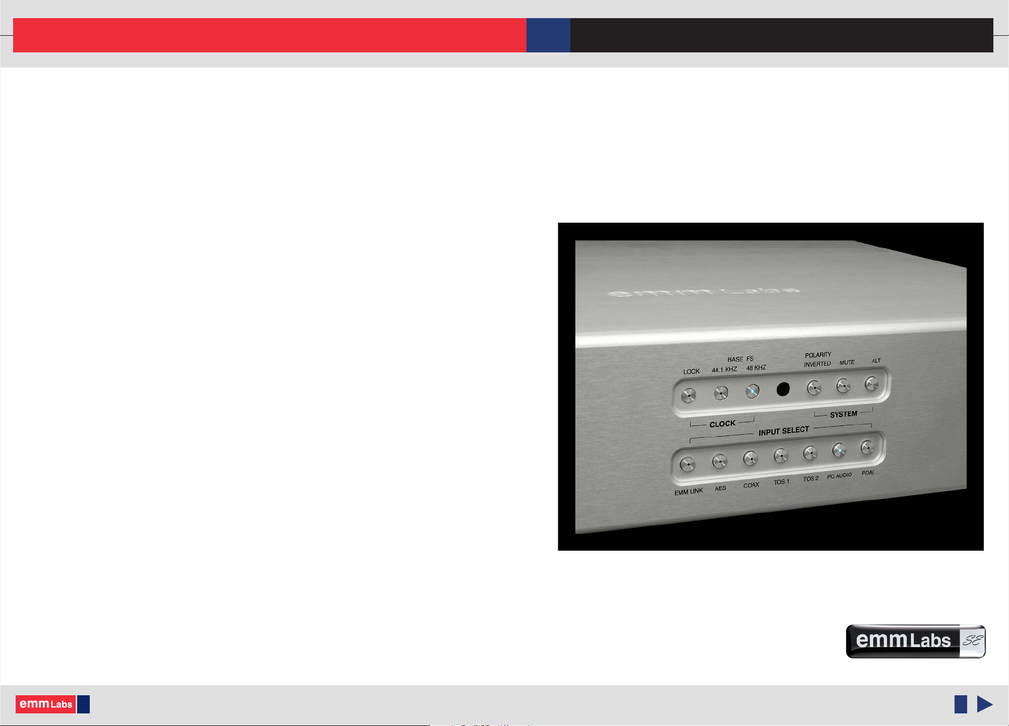
2. Clock Control Indicators:
LOCK: is indicator is lit when the unit detects valid digital clock at the selected
digital audio input. For normal operation with digital audio inputs this indicator has
to be lit or else all audio outputs will be muted.
44.1kHz / 48kHz: ese indicate the base frequency for the selected digital audio
input. Eg. digital inputs with sample frequencies of 44.1kHz or 88.2kHz the 44.1kHz
indicator will be lit. For digital inputs with sample frequencies of 48kHz or 96kHz
the 48kHz indicator will be lit.
© 2010 EMM Labs Inc., All Rights Reserved. EMM Labs reserves the right to amend specifications & design without notice.
Page 9

Front Panel & Functions
009
DAC2 AUDIO CONVERTER OWNER’S MANUAL
Front Panel & Functions
3. POLARITY INVERTED button:
When this button is lit the polarity of all analog outputs are inverted. e inversion is
performed in the digital domain.
4. MUTE button:
When lit all outputs are muted. Pushing the button again unmutes the outputs.
5. ALT button (intended for future use)
6. Digital input selector buttons:
• EMM LINK: Selects the EMM Optilink input for internconnection with an EMM
Labs transport. e cables used are ST glass (multimode) supplied with the
transport.
• AES: Selects AES/EBU (XLR) format PCM digital input . Sample rates up to 96kHz
are supported.
• COAX: Selects SPDIF (RCA) format PCM audio from COAX connector. Sample
rates up to 96kHz are supported.
• TOS1: Selects SPDIF (TOSLINK) format PCM audio from TOS1 connector. Sample
rates up to 96kHz are supported.
• TOS2: Selects SPDIF (TOSLINK) format PCM audio from TOS2 connector. Sample
rates up to 96kHz are supported.
• PC AUDIO: Selects USB PCM audio (computer, media player, media server).
44.1kHz and 48kHz sample rates are supported.
• PDAI - Switch and connector intended for future use.
PC Audio from USB input:
For best delity, care must be taken to ensure that as little processing is performed on the audio
data by the computer. In both Windows and OSX systems, the use of low-latency ASIO device
drivers are highly recommended.
© 2010 EMM Labs Inc., All Rights Reserved. EMM Labs reserves the right to amend specifications & design without notice.
Page 10

Rear Panel & Functions
Rear Panel & Functions
010
DAC2 AUDIO CONVERTER OWNER’S MANUAL
1. Main Power Switch
2. Main Power connector and fuse holder:
Main fuse holder as well as included spare fuse is located within this compartment.
3. Product VOLTAGE indicator:
Indicates working voltage of the DAC2. Only use with indicated line voltage.
4. Product model and serial number indicator:
Warranty void if model/serial number indicator is not attached to unit, missing or
damaged whereby serial number cannot be seen.
© 2010 EMM Labs Inc., All Rights Reserved. EMM Labs reserves the right to amend specifications & design without notice.
Page 11

Rear Panel & Functions
011
DAC2 AUDIO CONVERTER OWNER’S MANUAL
Rear Panel & Functions
5. Analog Line Output:
• Le and Right Balanced (XLR) Connectors
• Le and Right Un-Balanced (RCA) Connectors
• Level High/Low switch (Output Line Level with 0dBfs signal on AES/EBU input):
Low position: XLR outputs: 4V (+14.38dBu)
RCA outputs: 2V (+8.353dBu)
High position: XLR outputs: 7.2V (+19.38dBu)
RCA outputs: 3.6V (+13.34dBu)
6. Digital Inputs:
• EMM Optilink: input for interconnection with an EMM Labs transport.
• AES/EBU: AES/EBU (XLR) PCM digital input.
• COAX: SPDIF (RCA) format PCM audio.
• TOS1: SPDIF (TOSLINK) format PCM audio.
• TOS2: SPDIF (TOSLINK) format PCM audio.
• PC AUDIO: USB PCM audio from a computer, media player, server
• PDAI: Connector intended for future use.
7. System
Remote:
• External IR: wired infra-red communication port
• Wired RS232: RS232 communication port
Service:
• USB: soware update port please see Appendix A for details
• RESET: Used to access the backup BIOS in connection with soware
upgrades via the USB port. Should not be used during normal
operation. Please see Appendix A for details.
© 2010 EMM Labs Inc., All Rights Reserved. EMM Labs reserves the right to amend specifications & design without notice.
Page 12

Operation
012
DAC2 AUDIO CONVERTER OWNER’S MANUAL
Basic Operations and Input Connections
1. Memory:
Aer 10 seconds when no button has been pushed or changed, the DAC2 memorizes
its momentary setup in permanent memory for later retrieval aer the next powerup.
It will be recalled immediately aer the unit is turned on. Each individual input
selection will keep its last conguration before powerdown.
During normal operation each input selection will immediately memorize its
conguration so that switching between dierent sources with dierent congurations
can be accomplished with a single button selection.
2. DAC2 Input Connections
Just connect the appropriate digital source output to the specic DAC2 input, on the
back of the DAC2 and select the appropriate digital source from either the front panel
buttons or the remote control.
Typical front panel display when DAC2 is locked to 44.1kHz base frequency and the
© 2010 EMM Labs Inc., All Rights Reserved. EMM Labs reserves the right to amend specifications & design without notice.
Page 13

Operation
013
DAC2 AUDIO CONVERTER OWNER’S MANUAL
Basic Operations and Input Connections
2. DAC2 Input Connections (cont’d):
EMM Optilink is selected as the digital source (connected to an EMM Labs
transport).
Above is another example. Here the DAC2 is connected to an AES digital source with
a base frequency of 48kHz (PCM 48kHz or 96kHz audio). For AES connections the
DAC2 uses a single AES input to carry 2 channels of PCM audio up to 96kHz.
NOTE: If the LOCK light is not ON then the DAC2 is not receiving appropriate
digital audio from the digital source. e DAC2 will automatically mute all the
outputs if it does not receive a proper digital audio signal from the selected source.
Check the source setup and cable connections for problems.
3. Using the remote and pressing the “Display DAC” button turns o all the DAC2 LEDs
except the LOCK light.
© 2010 EMM Labs Inc., All Rights Reserved. EMM Labs reserves the right to amend specifications & design without notice.
Page 14

Operation
Basic Operations and Input Connections
4. TSD1+DAC2 Quick Connect:
Connect the EMM Optilink cable from the TSD1 to the DAC2
014
DAC2 AUDIO CONVERTER OWNER’S MANUAL
TSD1
DAC2
EMM Optilink Cable
Make sure the TSD1 is External Clock switch is set to internal
Using either the remote or the front panel of the DAC2 select EMM Link.
e LOCK light and the 44.1kHz sync. light both should be lit on the DAC2.
© 2010 EMM Labs Inc., All Rights Reserved. EMM Labs reserves the right to amend specifications & design without notice.
Page 15

Infrared Remote Control
015
Infrared Remote Control
e remote control provides combined functions for both the DAC2 and
EMM Labs transport. e functions that are relevant to the DAC2:
DAC2 AUDIO CONVERTER OWNER’S MANUAL
DAC:
INPUT:
POLARITY:
is function toggles the front panel LEDs ON or OFF on the DAC2
When in OFF mode only the LOCK LED would be lit.
ese buttons are used to select the digital source input:
• EMM : Selects the EMM Optilink input.
• AES : Selects AES/EBU format PCM digital audio via XLR
• COAX : Selects SPDIF format PCM digital audio via coax/RCA
connector
• TOS : Toggles between TOSLINK SPDIF format PCM audio
from either TOS1 or TOS2 connectors.
• USB : Selects USB PCM audio via USB interface.
• PDAI : Expansion port intended for future use.
Toggles the analog output polarity. Polarity inversion is performed
in the digital domain.
MUTE:
© 2010 EMM Labs Inc., All Rights Reserved. EMM Labs reserves the right to amend specifications & design without notice.
Mutes the outputs.
Page 16

Appendix A - Serial Remote Control (RS232)
016
DAC2 AUDIO CONVERTER OWNER’S MANUAL
Serial Remote Control (RS232)
e DAC2 is equipped with a 9-pin RS232 port for system remote control via a serial cable
(not provided by EMM Labs). Please use a standard RS232 cable. Do not use a null model
cable, as this will not work. RS232 communication port settings:
• 19,200 baud
• 8 bits
• 1 stop bit
• no ow control
• no parity bit
Commands to the DAC2
All commands sent to the DAC2 consist of 3 ASCII characters (all lowercase) followed by a
carraige return or <CR>. Repeating a <CR> will repeat the last command sent. Received
commands are not stored in a stack. ey need to be sent in intervals of at least 50ms to
allow enough time for the DAC2 to execute a command before receiving the next one.
Command Function
pol Toggles the analog output polarity
mut Mutes the outputs
emm Selects the EMM Optilink input
aes Selects AES/EBU format PCM digital audio via XLR
cox Selects SPDIF format PCM digital audio via coax/RCA connector
to1 Selects TOSLINK format PCM digital audio via TOS1 connector
to2 Selects TOSLINK format PCM digital audio via TOS2 connector
© 2010 EMM Labs Inc., All Rights Reserved. EMM Labs reserves the right to amend specifications & design without notice.
Page 17

Appendix A - Serial Remote Control (RS232)
017
DAC2 AUDIO CONVERTER OWNER’S MANUAL
Commands to the DAC2 (cont`d)
Command Function
usb Selects USB PCM audio via USB interface
Status bytes sent from DAC2
e DAC2 sends back 4 Bytes terminated with a <CR> whenever any status changes.
<Byte 0><Byte 1><Byte 2><Byte 3><CR>
Byte 0 ASCII ' 0 ' - Not Used
Byte 1 ASCII ' 0 ' - Not Used
Byte 2
bit 0 Not Used
bit 1 Not Used
bit 2 Status of EMM Link input (0 when selected)
bit 3 Status of USB input (0 when selected)
bit 4 Status of AES input (0 when selected)
bit 5 Status of Coax input (0 when selected)
bit 6 Status of TOS1 input (0 when selected)
bit 7 Status of TOS2 input (0 when selected)
Byte 3
bit 0 Lock Status, 1 when locked
bit 1 Not Used
bit 2 0 when 44.1kHz selected as base sample frequency
bit 3 0 when 48kHz selected as base sample frequency
bit 4 Status of polarity of analog outputs (0 when inverted)
© 2010 EMM Labs Inc., All Rights Reserved. EMM Labs reserves the right to amend specifications & design without notice.
Page 18

Appendix A - Serial Remote Control (RS232)
Status bytes sent from DAC2 (cont`d)
Byte 3
bit 5 Not Used
bit 6 Status of mute (0 when muted)
bit 7 Not Used
Byte 4 <CR> (0x0D)
018
DAC2 AUDIO CONVERTER OWNER’S MANUAL
© 2010 EMM Labs Inc., All Rights Reserved. EMM Labs reserves the right to amend specifications & design without notice.
 Loading...