

Page 1

Three-Piece ball valve
EA-307 User Manual
English Version
[DRAFT VERSION]
For use for company in Europe who will place the product on the market.
Please amend which necessary.
EA-307 Series
PED Category I, II
Document No: 3-29-06
Date: 92/6/10
Version: 1
PREPARED BY
REVIEWED BY
APPROVED BY
DATE
DATE
DATE
Eayuan Metal Industrial Co., Ltd.
3F-8, No. 665, Sec. 2, Wu Chuan W Rd.,
T aichung, Taiwan, R.O.C.
Page 2

Contents
1. General Precautions
2. Product Description
3. Design Specification
4. Pressure Temperature Ratings
5. Delivery Condition and Storage
6. Installation and Operation
7. Maintenance
Page- 2~3
Page- 4~6
Page- 7
Page- 7~8
Page- 8
Page- 9~12
Page-13~15
8. Torqure Data
9. Corrosion Data
Page-16
Annex 1.
1
Page 3

1.General Precautions
a. Material Selection:
The possibility of material deterioration in service and the need for periodic
inspections is depended on the contained fluid. Carbide phase conversion to
graphite, oxidation of ferrite materials, decrease in ductility of carbon steels at
low temperature (even in applications above -29℃) are among those items. Even
information about corrosion data is provided in this user manual, the user is
requested to take attention or consideration to determine the suitability of material
in their application.
b. Pressure-Temperature rating:
The Pressure-Temperature rating is considered for static pressure. Please refer to
P & T rating section on page 9 for working precaution. The allowable temperature
is between -29℃ and 180℃, Do not exceed the temperature range to avoid
danger accident happen.
c. Fluid thermal expansion:
Pressure, built-up in the body cavity by heating volatile fluid, can damage the
seats or the ball. The hole in the ball beneath the stem slot can equalize pressure
between body cavity and the line when valve in the open position. An optional
internal pressure equalizing hole drilled in upstream side of ball is suggested for
certain applications e.g. ammonia, chlorine, LPG, for pressure equalization when
valve in the close position.
d. Static electric effect:
The ball valves are provided with anti-static devices for ball-stem-body. When
service conditions require electrical continuity to prevent static discharge, the user
is responsible for specifying static grounding.
e. Fire safe condition:
Generally, the application of the valve shall comply with the
Pressure-Temperature rating range. If the risk of fire is major effect, user is
recommended to select our fire-safe products, which with API-607 4th edition
approval. Contact to the valve distributor or manufacturer for details.
f. Liquids with high fluid velocity:
When ball valves must be operated frequently on liquids with very high velocity,
a check shall be made with the valve distributor or manufacturer for appropriate
2
Page 4

advice to minimize the possibility of seat deformation, especially when they are
highly pressurized on high-temperature line.
g. Throttling service: Ball valves are generally not recommended for throttling
service, where both the fluid flow and the leading edge of the ball can damage or
deform the resilient ball seats causing leakage. High fluid velocity or the presence
of solid particles in suspension will further reduce seat life in throttling
applications.
h. Do not open the bonnet or cap when bearing pressure. Valve is not equipped with
pressure access device. User should check it by other method through its piping
system.
i. No touch the surface of valve on high temperature.
j. Not allowed for unstable fluid, otherwise specified with catogory III in
Declaration of conformity or/and in this user manual.
k. Lock design on the handle to avoid the valve operated by non-related people is
optional requested by the user.
3
Page 5

2. Product Description
2.1 Feature
a. STANDARD type, FULL BORE ball valve.
b. Blowout proof stem.
c. Anti-static devices for ball-stem-body.
d. Pressure balance hole in ball slot.
e. Pressure self-relief seat to prevent pressure built up.
f. Lock design on the handle is optional
2.2 Product specification
The scope of product specifications are as following
DN PN63 DN PN63
DN15 Art .3 para. 3 DN50 Category II
DN20 Art .3 para. 3 DN65 Category II
DN25 Art .3 para. 3 DN80 Category II
DN32 Category II DN100 Category II
DN40 Category II
2.3 Material of construction and Common dimension
307-1/2”~2”see Fig-1
307-2-1/2”~4” see Fig-2
4
Page 6
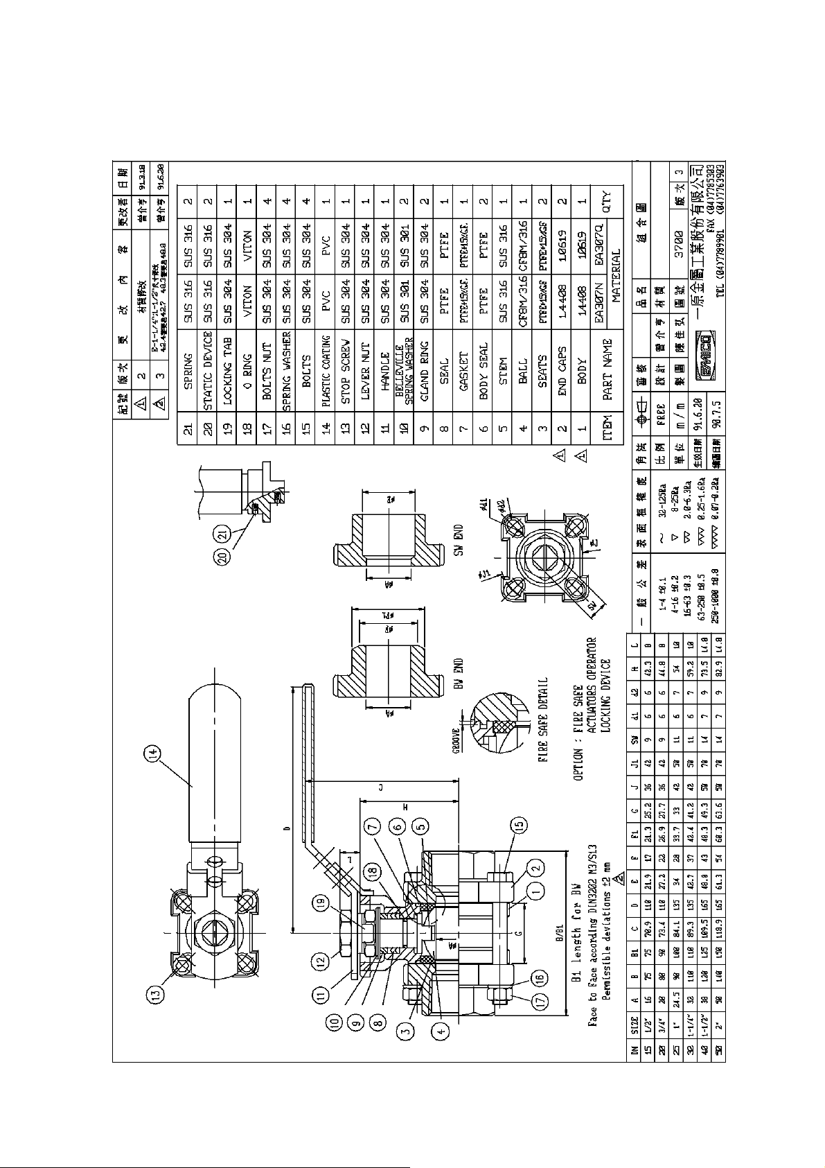
Fig-1
5
Page 7
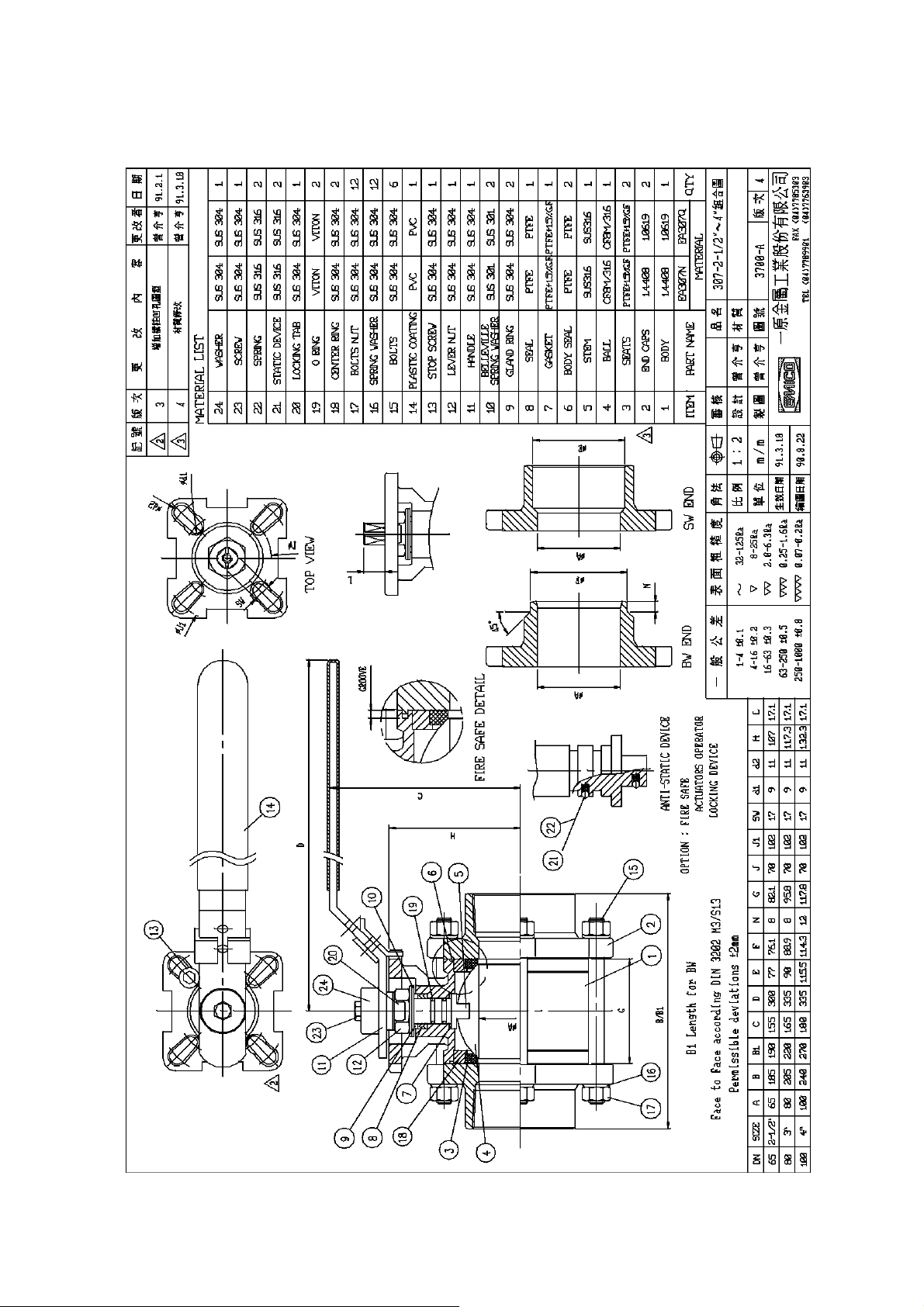
Fig-2
6
Page 8
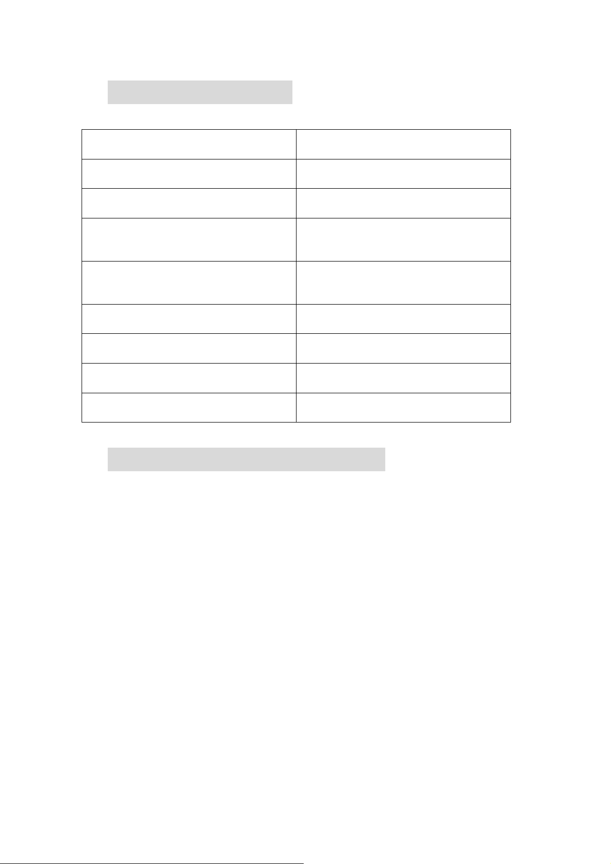
3. Design Specification
Items Standards/Codes
Standards of Design (P-T rating) prEN 12516-1
Testing prEN 12266-1
DIN- 2999or259 (screw type)
Connection
Face to Face
Mounting Pad ISO-5211
Stem DIN-79
DIN- 3239 (Butt weld type part1)
DIN- 3239 (socket weld type part2)
DIN- 3202-M3(screw type &
socket weld type)
DIN- 3202-S13(Butt weld type)
Material of Casting (Body, Cap, Ball)
Bolt and Nut ISO-3506 (A2-70)
EN 10213-4 1.4408 & 1.4308
EN 10213-2 1.0619
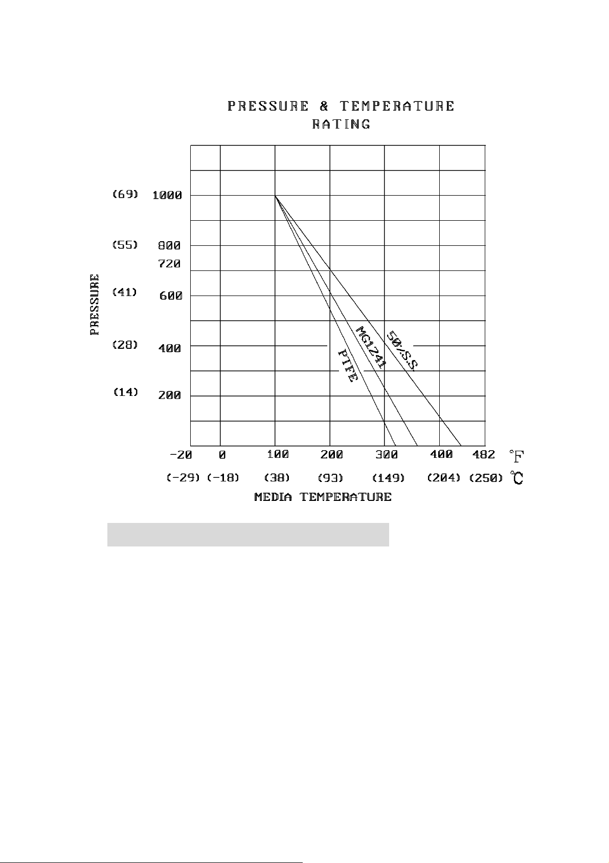
4. Pressure Temperature Ratings
The pressure-temperature rating of ball valves are determined, not only by valve shell
materials, but also by sealing materials used for ball seats, stem packings, and body seal.
Sealing materials may be high molecule, elasticity and hardness. However, the choice is
limited by the characteristics of the service fluid, temperature, pressure, velocity of fluid,
frequency of valves operation and sizes of ball valves etc. Followings are the general
rating charts for non-shock fluid service for floating ball valves distinguished by sizes and
seating materials, please refer to section 1, General precaution.
7
Page 9
5. Delivery Condition and Storage
Valves stay in the open condition during the transportation. For incoming QC, it must
check:
a. Packing condition: Is there any damaged during the transportation.
b. The bolts of cap: to make sure the bolt does not loose tightness when it arrived.
Valves must store in an indoor warehouse to avoid dusts and other foreign object, do
not exposed in an open space without to put a cover over or take off the packing under
an unnecessary situation.
8
Page 10

6. Installation and Operation
6.1 Handling
During the ball valve installation, it must follow the procedure to hold at the both
sides of the body. Bigger valves required a hoist to lift must be lifted at both sides of
the body. The sling must be strong enough to ensure the safety during the
installation.
6.2 Cleaning
Even the valves was transported under a clean environment, operator must check is
there any foreign body or dusts inside the bore. If yes, clean it before installation.
Operator clean the valves by water, compression air, or steam (automation valve shall
be cleaned only with water or steam, the compression air is not allowed.) For
cleaning, first is to put the valve bore perpendicular to the ground and clean. Ensure
all the dusts can be removed from the bore. The second is to check and to clean all
the connecting pipe bore and connection area. No flush, rust and foreign bodies are
allowed to avoid the blocking and leakage.
6.3 Valve Installation (Install to the pipeline system)
a. Direction
Most of the valves do not restrict the flow direction.
b. Position
The body, cap and gasket are in the connection area of ball valve and pipeline.
The bear weight ability and gradient are very important to the pipe installation.
Do not make the pressure from the pipeline and stress to concentrate on the
connecting area of body and cap. It will cause the deformed and leakage, and
the ball, seat, and stem will stick, leaking, and damaged.
c. Fittings
1.Screw end--- Fig-3
1.1.Before installation, clean ball valve and pipe fitting up to remove any dusts
or foreign object or any tiny metal chips.
1.2.Check if the threaded type of ball valve is the same as it of pipe.
1.3.Wrap tap seal or other sealing material around threads of pipe 2 – 3 circles.
1.4.Hold end cap of valve with wrench and hold pipe end tightly with pipe
wrench. Rotate pipe by clockwise until they joint tightly.
1.5.After installation finished. Apply soap bubbles on the joint points to check
if the pipeline is sealed properly.
9
Page 11
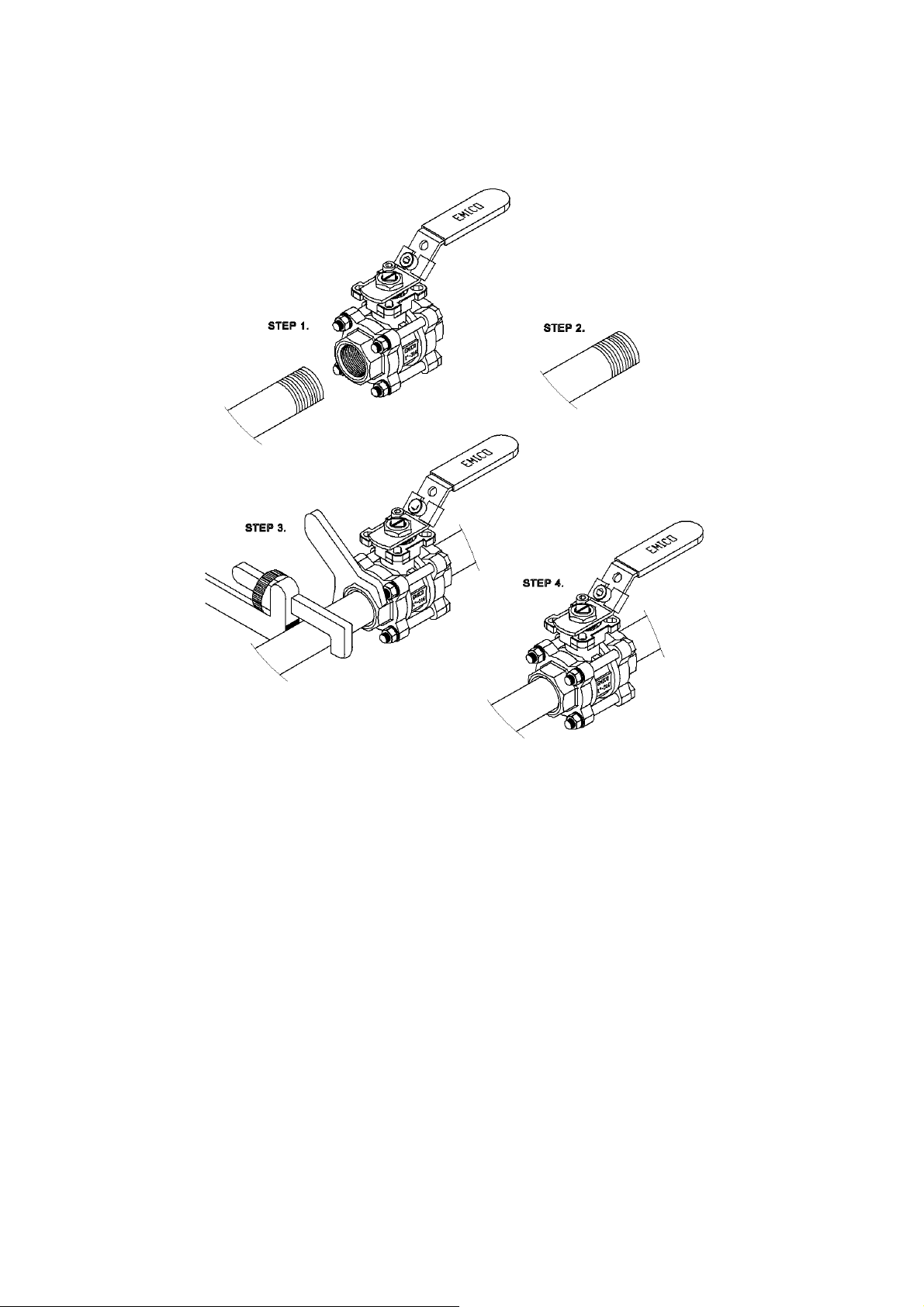
Fig-3
2.Welding end--- Fig-4
2.1.Before installation, clean ball valve and pipe fitting up to remove any
dusts or foreign object or any tiny metal chips.
2.2.Disassemble body and end caps by loosen screws. Take body apart.
2.3.Weld end caps at pipeline. (Note the concentricity and parallel between
two end caps)
2.4.After the temperature at welding section cool down, connect body and end
caps. (tighten bolts by symmetrical order)
2.5.After installation finished. Apply soap bubble on the joints to check if
the pipeline is sealed properly or not.
10
Page 12
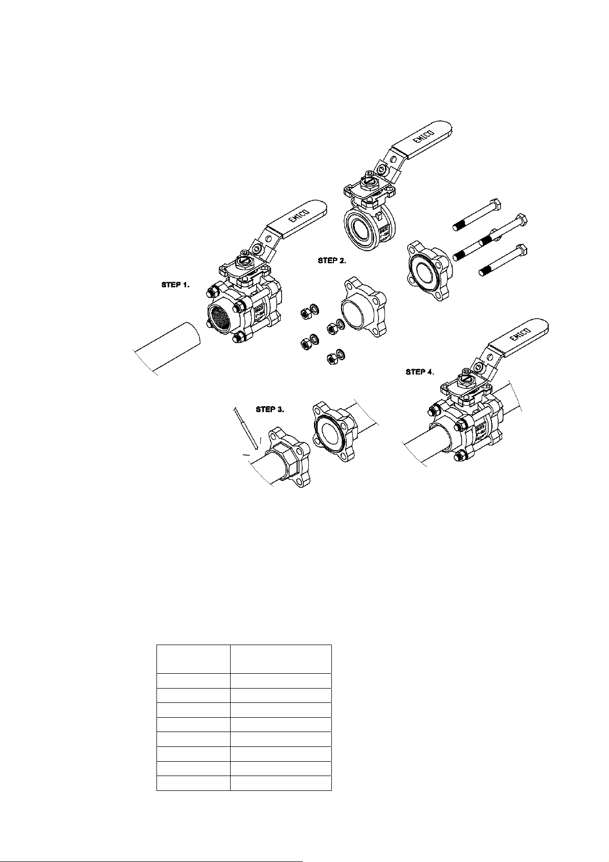
Fig-4
d. Systems hydrostatic test
Before delivery, valves are tested 1.5 times the allowable pressure at ambient
temperature in open position. After installation, the piping system may subject to
system tests, as condition not to exceed the allowable pressure.
6.4 Actuator installation
The ball valves are provided with ISO 5211 actuator attachment. Following is the
flange type against sizes of the ball valves.
SIZ
E
DN15 F03~F04
DN20 F03~F04
DN25 F04~F05
DN32 F04~F05
DN40 F05~F07
DN50 F05~F07
DN65 F07~F10
DN80 F07~F10
Mounting
Pad
11
Page 13

DN100 F07~F10
The sizes of actuator and setting of the input power or pressure of actuator are
depended on the operation torque. The following table lists the maximum torque
values of each flange type. User is recommended to refer to the instruction of
actuator supplier. Overload torque applied by the actuator may transfer the
un-intended load to ball valve itself or to the piping joints. Setting of the input
power or pressure of the actuator is better not to exceed 1.5 times of the operation
torque data.
6.5 Operation
a. For manual operation, shift the handle in counter clockwise direction for close
and clockwise for opening.
b. If the handle is parallel to the flow direction, the valve is open. If the handle is
right-angled to the flow direction, the valve is close.
c. When installing actuator or the valve is operated with removable handle, the user
should ensure the position of the valve whether open or close. There is a sign at
the top of stem for square type stem. Fig-5 below shows how to access the position
of ball valve.
12
Page 14
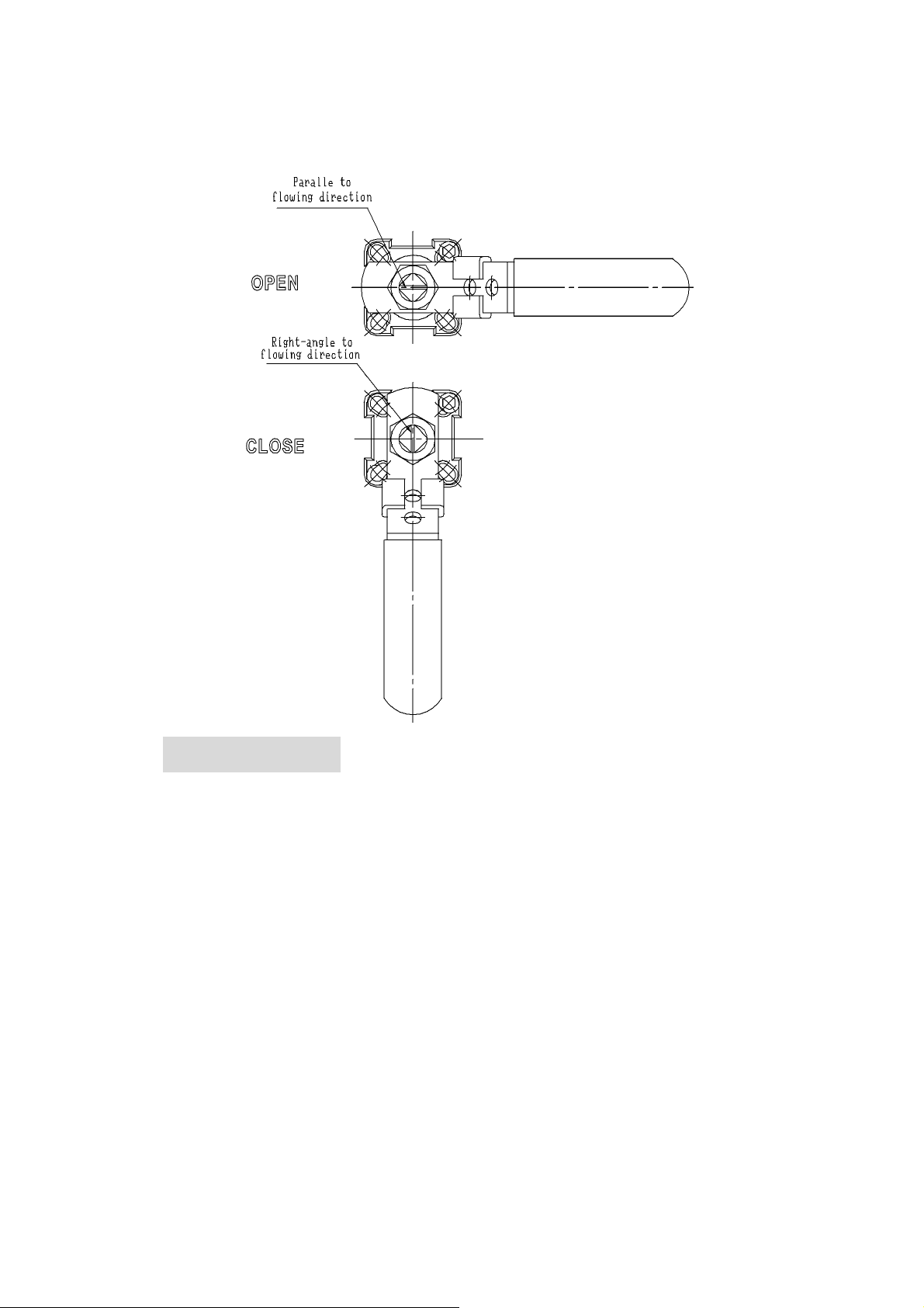
Fig-5
7. Maintenance
7.1 Maintenance frequency
The maintenance frequency is determined upon the application of ball valve. User shall
consider the time interval depend on the kinds of fluid, flow velocity, operation
frequency, high-pressure effect and high-temperature effect etc.
7.2 Disassembly
a. The user should check if the kits of EA-307 are available in the local market. If not,
please do not disassemble the valve, otherwise, please make an order from the original
manufacturer for the kits of EA-307.
b. To dismantle the valve must follow the procedure and drawings below.
c. Make sure there is no fluid left inside valve before disassembly. The correct position
to store the valves is to put the flange end on cardboard or a wooden pallet on a stable
platform or ground.
13
Page 15
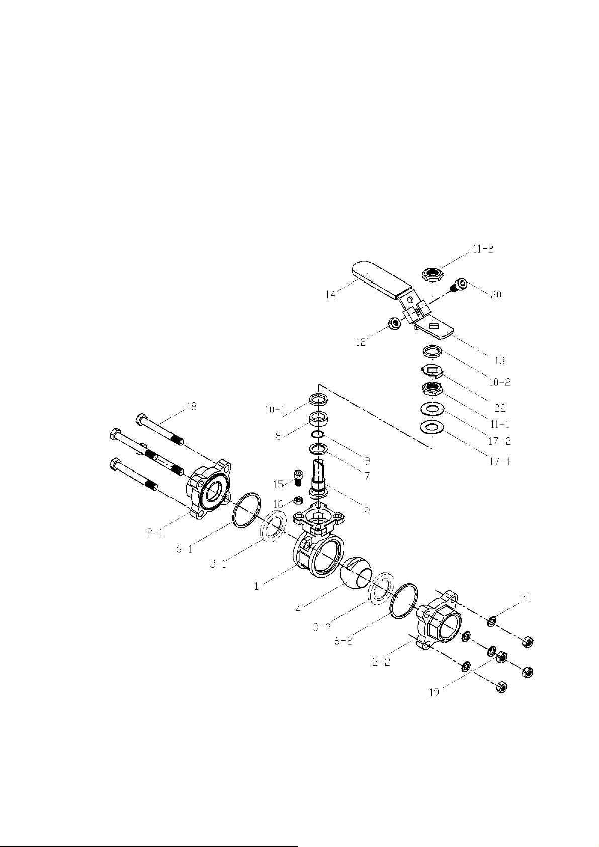
d. For valve with hand wheel, it is necessary to dismantle the hand wheel form the valve
first, then put the valve flange end as above item c.
e. To dismantle the valve body and end cap, release the bolts symmetrically. It must be
careful to dismantle the ball to avoid the seat retainer fall down from end cap.
f. To take ball out, it is necessary to turn the ball in the close position.
g. To lift the ball by hoist, it is necessary to make the protection at the corner to avoid the
ball damaged by metal contacted.
7.3 Parts inspection, maintenance, and replacement:
a. Check if the surface of ball is scraped? It may use the PT for inspection if
necessary. If there is any damaged on the surface, find out the root cause such as
14
Page 16

the dirt fluid…etc. It must avoid the damage factors as far as possible.
b. If the ball surface is damaged, check if it locates at the contacting area of ball and
ball seat? If so, the ball must take a fine milling. If it is damaged heavily, and
cannot be repaired, then change a new ball.
c. If the scraped area is not at the location described in the item b above, it is
necessary to re-fine milling the damage area again. Otherwise, the ball will
damage the soft seat during the open and close operation or it will dig out the ball
seat and cause serious leakage.
d. To inspect the surface of soft seat, if it has any scrape mark, concave, dusts
(including weld dregs, iron bit, sands…etc.), abrasion, abnormal press scrape, or a
tiny scrape. Usually, the scrape mark and damage by dusts will occur the same
time as ball damaged. It is the root cause for leakage. If leakage occurs before
repairing, then suggest to change a new soft seat (PTFE or RPTFE). The mark
from press or fine scrape is happen in an abnormal operation pressure. It must
reconsider to choose a right valve.
e. The gland packing must be replaced by the new parts after dismantle the valve.
The material of it can be PTFE, Grafoil or PTFE + Glass Fiber. The material of
new packing must be the same as the old one. To tight the gland nut, please see
Section 9 for torque data.
f. To do the final inspection for a valve, it must operate 10 times of open and close to
ensure all the parts are assemble correctly. To ensure the torque is in the same
value during the open/close operation. If the torque is not the same during
operation, it may have some parts in an incorrect position or interference. It must
be dismantled and re-assembly. Otherwise, it is easy to damage if valve works in
a pipeline under higher pressure.
7.4 Assembly
For assembly process, it takes the opposite way of dismantle process. The ball must
be at the close position when assembling the body and end cap. The stopper must
locate at the right place. Otherwise, the open and close operation will be opposite.
15
Page 17
8. Torque Data
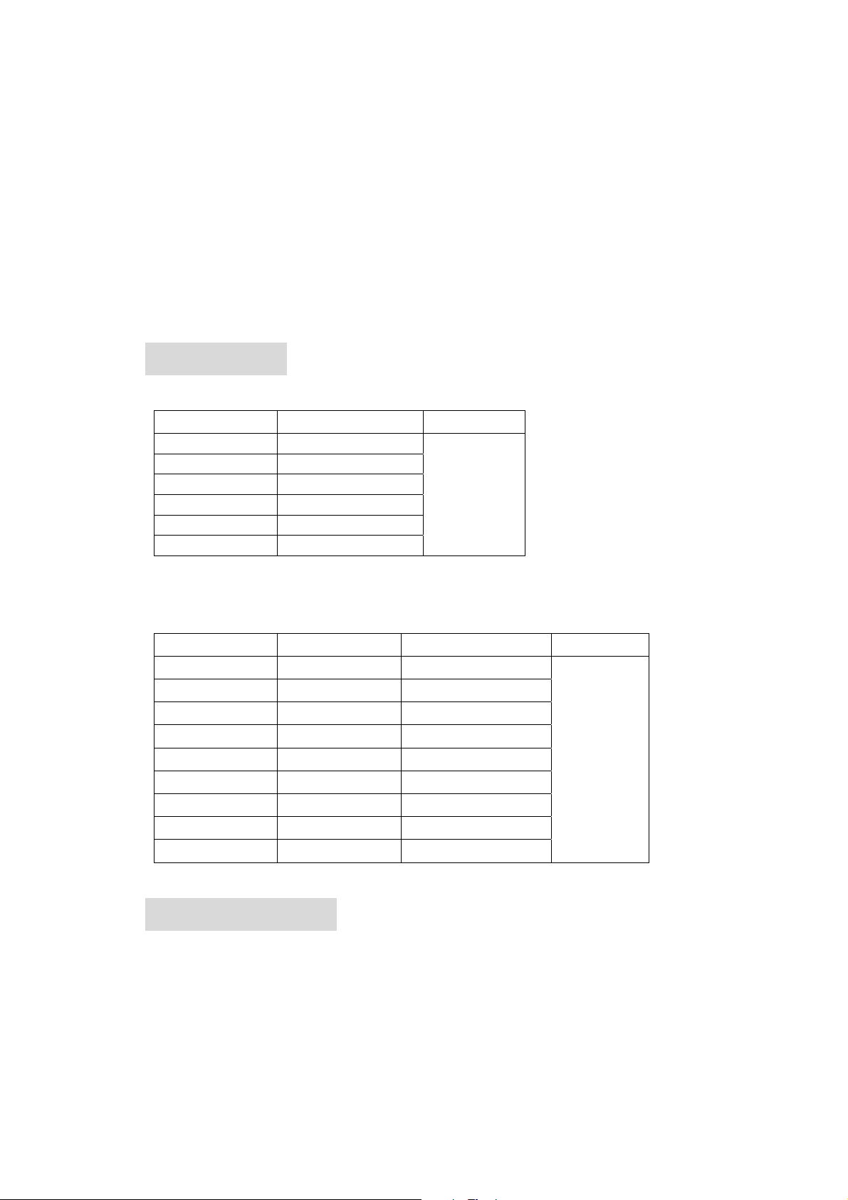
Stem Nut
SIZE
1/2”;3/4” 4
1”;1-1/4” 4.5
1-1/2”;2” 5.5
2-1/2” 7
3” 7
4” 7
鎖緊扭力(N-m) 公 差
+-10%
Bolt&Nut
SIZE
1/2”
3/4”
1”
1-1/4”
1-1/2”
2”
2-1/2”
3”
4”
牙式 鎖緊扭力(kgf-cm) 公 差
M6 190
M8 220
M8 250
M10 310
M10 410
M10 410
M12 1000
M16 1220
M16 1430
9. Corrosion Data
The following corrosion data is for information only.
Annex 1.
+-10%
16
 Loading...