


14 |
|
|
|
|
|
18 |
|
|
|
|
15 |
|
|
|
|
|
|
|
|
|
12 |
|
|
|
|
|
|
|
|
|
|
|
|
|
|
|
|
|
|
|
|
|
17 |
|
|
|
|
2 |
|
|
|
|
20 |
25 |
|
|
|
|
|
13 |
|
26 |
|
23 |
|
1 |
|
||
|
|
|
|
|
|||||
|
|
|
|
|
|
||||
|
|
|
|
|
|
|
19 |
3 |
|
|
|
|
|
|
|
|
24 |
|
|
|
|
|
|
|
|
|
|
|
|
|
|
|
|
|
|
|
|
21 |
|
|
|
16 |
22 |
|
|
|
|
|
|
|
|
|
|
|
|
|
24 |
21 |
|
|
|
|
|
|
|
|
|
||
|
|
|
|
|
|
9 |
|
|
|
|
|
TO 12 |
|
|
|
|
|
|
4 |
|
|
PRESSURE |
|
|
|
|
|
|
|
|
|
SWITCH |
|
|
|
|
|
|
|
|
|
11 |
|
|
|
|
|
|
|
|
|
|
|
|
|
|
|
TO 19 |
|
|
|
|
|
|
|
|
|
ELBOW |
|
|
|
|
|
|
|
|
|
5 |
|
|
|
10 |
|
|
|
|
|
6 |
|
|
|
|
|
8 |
|
|
7 |
|
|
|
|
9 |
|
|
|
|
|
||
|
|
|
|
|
|
|
|
|
|
|
|
|
|
|
|
|
|
JENNY PRODUCTS, INC. |
|
|
|
|
MODEL AM780 - HC4V |
|
850 N. Pleasant Ave. |
|
|||
Copyright 2006 |
|
|
|
Somerset, Pennsylvania 15501 |
|
||||
|
|
|
|
|
|
|
|
|
|

Jenny Products, Inc.
850 North Pleasant Avenue
Somerset, PA 15501-1069
Ph: 814-445-3400
Fx: 814-445-2280
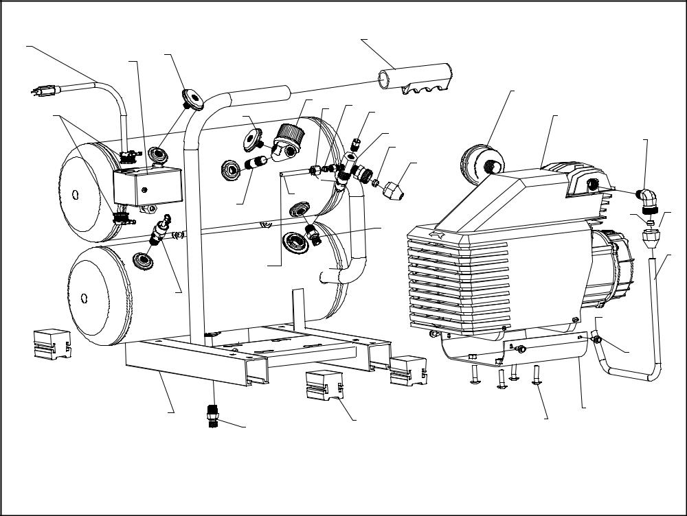
Parts List for Model AM780-HC4V
NOTE: The quantity number indicates the total number of pieces required for a complete unit repair. When ordering parts give compressor model, serial number and part number. Order assemblies when possible.
REF. NO. |
PART NO. |
DESCRIPTION |
QTY. |
1 |
421-1710 |
PUMP,CMPRSR,PISTON,REPLCMT(1010),AM780 |
1 |
|
|
|
|
2 |
630-317007000 |
FILTER,AIR,PUMP,AM39/77/78/840,39154 |
1 |
3 |
121-1035 |
ELBOW,MALE,COMPRESSION,BR,3/8TBX3/8"NPTM |
1 |
|
|
|
|
4 |
610-1369 |
AFTERCOOLER,ELCTRC,AM780,SLV&NT,3/8,HC4V |
1 |
5 |
120-1177 |
SCREW,SELF DRILL,HEX,ST,PL,12 X 3/4 |
4 |
|
|
|
|
6 |
320-1130 |
SADDLE,STL,PLTD,W/HARDWARE,AM780/790 |
1 |
7 |
120-1276 |
SCREW,BT,HC,ST,BL,1/4-20 X 3/4" |
4 |
|
|
|
|
8 |
104-1193 |
PAD,RUBBER,SQUARE,1.5UNI-STR,40D,PAD-40B |
4 |
9 |
141-1058 |
DRAIN,PETCOCK,BRASS,1/4"NPTM,DC14 |
2 |
|
|
|
|
10 |
411-1017 |
TANK,HNDCRY,4G,NON,AM39&78,HC4V,RPLMT |
1 |
11 |
141-1004 |
VALVE,SAFETY,ASME,1/4",165 PSI,SV165 |
1 |
|
|
|
|
12 |
140-1074-015 |
SWITCH,PSI,2HP,100-125#,UNLD&LVR,PBVL5UN |
1 |
13 |
123-1029 |
CONNECTOR,ROMEX,CLAMP,STRAIGHT,3/8" |
2 |
|
|
|
|
14 |
123-1026 |
CORD,DROP,SJOW,5-15PLUG,15A,14/3,6 FT |
1 |
15 |
142-1003 |
GAUGE,PSI,200#,BK MT,JENNY,1.5,1/4",PG14 |
1 |
|
|
|
|
16 |
122-1137 |
NIPPLE,CLOSE,STEEL,SCH 40,PLATED,1/4" |
1 |
17 |
360-1108 |
REGULATOR,PRESSURE,AIR,W/PG18,1/4"N,R14 |
1 |
|
|
|
|
18 |
104-1072 |
GRIP,HANDLE,RUBBER,YELLOW,7/8",STERILE |
1 |
19 |
141-1099 |
VALVE,CHECK,1/2"M,90 DEG,3/8"COMPRESS |
1 |
|
|
|
|
20 |
121-1025 |
CONNECTOR,MALE,COMPRESSION,BR,1/4TBX1/8" |
1 |
21 |
121-1121 |
NUT,COMPRESSION,TUBING,BRASS,3/8"LONG |
2 |
|
|
|
|
22 |
610-1074 |
TUBE,UNLOADER,W/SLEEVE,HC4V,ASSY |
1 |
23 |
141-1065 |
VALVE,START,COLD,1/8"MNPT |
1 |
|
|
|
|
24 |
121-1081 |
SLEEVE,COMPRESSION,BRASS,3/8" |
2 |
Copyright 2006 Jenny Products, Inc. |
Page 1 of 2 |

Jenny Products, Inc.
850 North Pleasant Avenue
Somerset, PA 15501-1069
Ph: 814-445-3400
Fx: 814-445-2280
Parts List for Model AM780-HC4V
NOTE: The quantity number indicates the total number of pieces required for a complete unit repair. When ordering parts give compressor model, serial number and part number. Order assemblies when possible.
REF. NO. |
PART NO. |
DESCRIPTION |
QTY. |
25 |
121-1080 |
SLEEVE,COMPRESSION,BRASS,1/4" |
1 |
|
|
|
|
26 |
142-1002 |
GAUGE,PSI,200#,BK MT,JENNY,1.5,1/8",PG18 |
1 |
Copyright 2006 Jenny Products, Inc. |
Page 2 of 2 |
|
|
1 |
|
|
|
|
|
|
|
|
|
|
2 |
|
|
|
|
|
|
|
|
|
5 |
3 |
|
|
|
|
|
|
|
|
|
6 |
|
|
|
|
|
|
|
|
|
|
|
|
|
|
|
|
|
|
|
|
|
7 |
8 |
|
|
|
|
|
|
|
|
|
|
|
|
|
|
|
|
|
|
|
|
10 |
9 |
|
|
|
|
|
|
|
|
|
11 |
|
|
|
|
|
|
|
|
|
15 |
12 |
|
|
|
|
|
|
|
|
|
|
13 |
27 |
|
|
|
|
|
|
|
|
|
14 |
|
|
|
|
|
|
|
|
|
|
16 |
|
|
|
|
|
|
|
|
|
17 |
|
|
|
|
|
|
|
|
|
|
|
|
|
|
|
|
32 |
|
|
35 |
21 |
|
|
|
|
|
31 |
|
34 |
|
||
18 |
|
|
|
30 |
33 |
|
|
|||
|
|
|
|
|
|
|
|
|||
|
|
|
|
|
|
|
|
|
||
19 |
24 |
|
28 |
29 |
|
|
Jenny Products, Inc. |
|
||
26 |
|
|
|
|
||||||
|
|
|
850 North Pleasant Avenue |
|||||||
20 |
|
|
|
|
|
|||||
|
|
|
|
|
|
Somerset, PA 15501 |
|
|||
21 |
22 23 |
|
|
|
|
|
Ph: 814-445-3400 |
|
||
|
25 |
|
|
|
|
|
Fx: 814-445-2280 |
|
||
Copyright 2006 |
|
|
|
|
|
|
www.jennycompressor.com |
|||

Jenny Products, Inc.
850 North Pleasant Avenue
Somerset, PA 15501-1069
Ph: 814-445-3400
Fx: 814-445-2280
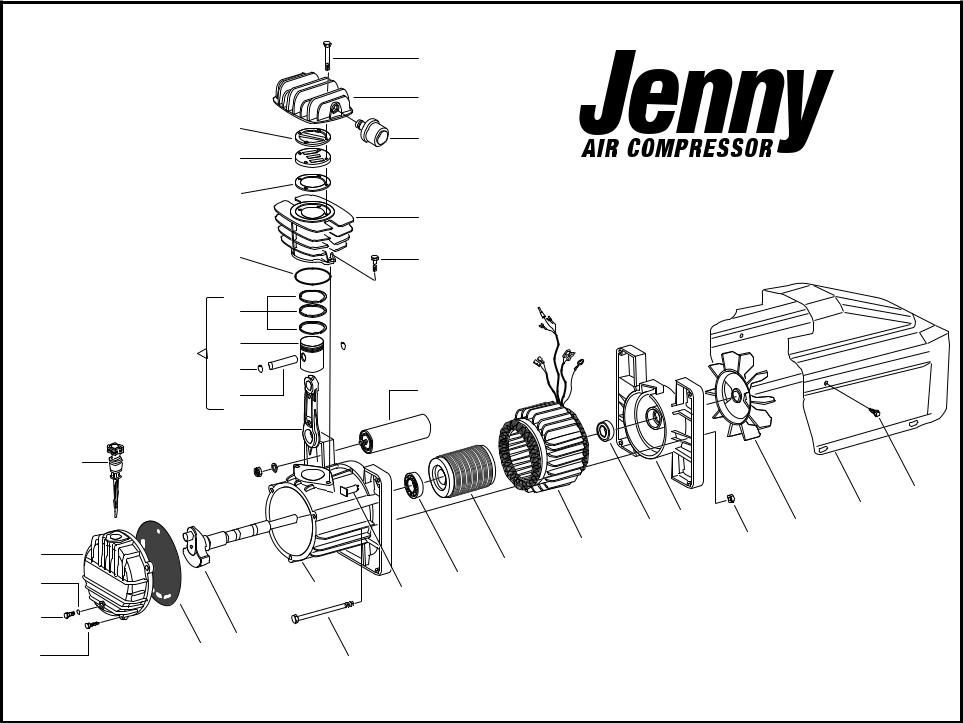
Parts List for Model AM780 Pump
NOTE: The quantity number indicates the total number of pieces required for a complete pump repair. When ordering parts give compressor model, serial number and part number. Order assemblies when possible.
REF. NO. |
PART NO. |
DESCRIPTION |
|
QTY. |
1 |
630-014002021 BOLT,HEAD,M6 X 45,AM39, 3952 |
|
4 |
|
|
|
|
|
|
2 |
630-116001001 |
HEAD,COMPRESSOR,AIR,ALUM,3/8",AM78,(7850) |
1 |
|
3 |
630-317007000 |
FILTER,AIR,AM39/77/78/840, 39154 |
See also #38 |
1 |
|
|
|
|
|
4 |
630-116022038 |
REED,VALVE,AM39/77, 3947 (Not Shown) |
2 |
|
5 |
630-116022009 |
GASKET,HEAD,AM39/77, 3951 |
|
1 |
|
|
|
|
|
6 |
630-116022013 |
PLATE,VALVE,AM39/77,(3940) |
|
2 |
6A |
630-116022012 |
GASKET,PLATE,VALVE,AM39/77,(3941) |
(Not Shown) |
1 |
|
|
|
|
|
7 |
630-116022010 |
GASKET,CYLINDER,TOP,AM39/77,(3912) |
1 |
|
8 |
630-116001006 CYLINDER,CAST IRON, AM78,MK200, 7830 |
1 |
||
|
|
|
|
|
9 |
630-014001044 |
BOLT,CYLINDER,39/78,(398) USE (788) |
2 |
|
10 |
630-116022029 |
GASKET,CYLINDER,BOTTOM,AM39/77,(3931) |
1 |
|
|
|
|
|
|
11 |
630-216022002 |
SET,RING,PISTON, AM39/77,(39133) |
|
1 |
12 |
630-116022004 |
PISTON,AM39/77,(3932) |
|
1 |
|
|
|
|
|
13 |
630-015001000 |
CLIP,PIN,WRIST,AM39/77,(3936) |
|
2 |
14 |
630-116022040 |
PIN,WRIST,AM39/77,(3935) |
|
1 |
|
|
|
|
|
15 |
630-416022004 |
KIT,PIN&PISTON&RINGS,AM39/77/78,(39132) |
1 |
|
16 |
630-116091021 |
ROD,CONNECTING,AM39/77/78/99,(3921) |
1 |
|
|
|
|
|
|
17 |
630-012008000 |
DIPSTICK,GRIP,RED,AM39/77(3914) |
|
1 |
18 |
630-016032014 |
COVER,END,AM39/77,(392) |
|
1 |
|
|
|
|
|
19 |
630-010072000 |
RING,O,PLUG,DRAIN,OIL,M800,(8004) |
|
1 |
20 |
630-014013024 |
PLUG,DRAIN,OIL,AM39/77/78/403,(3913) |
|
1 |
|
|
|
|
|
21 |
630-014006121 |
SCREW,4.2 X 13,AM99,(396) |
|
5 |
22 |
630-116001025 |
SEAL,COVER,END,AM390/780/790,(3924A) |
1 |
|
Copyright 2006 Jenny Products, Inc. |
Page 1 of 2 |

Jenny Products, Inc.
850 North Pleasant Avenue
Somerset, PA 15501-1069
Ph: 814-445-3400
Fx: 814-445-2280
Parts List for Model AM780 Pump
NOTE: The quantity number indicates the total number of pieces required for a complete pump repair. When ordering parts give compressor model, serial number and part number. Order assemblies when possible.
REF. NO. |
PART NO. |
DESCRIPTION |
QTY. |
23 |
630-116032006 |
CRANKSHAFT,AM39/77,(3920) |
1 |
24 |
630-116022051 |
CRANKCASE,AM39/77,(391) |
1 |
|
|
|
|
25 |
630-116011038 |
BOLT,M6 X 130,AM390/780/800,(3926) |
2 |
26 |
630-008030000 |
SWITCH,OVERLOAD,20AMP,AM77-78, 7842 |
1 |
|
|
|
|
27 |
630-009200035 |
CAPACITOR,60MF,AM77/780/, 7819 |
1 |
28 |
630-6205-2RS |
BEARING,END,COMPRESSOR, AM39/77/78,(399) |
1 |
|
|
|
|
29 |
N/A |
N/A |
N/A |
30 |
N/A |
N/A |
N/A |
|
|
|
|
31 |
630-6203-2Z |
BEARING,END,MOTOR,AM39/77/78, 999 |
1 |
32 |
630-116011001 |
COVER,END,MOTOR,AM39/77,(3928) |
1 |
|
|
|
|
33 |
630-014003002 |
NUT,M6,AM39/77,AM204,AM761,(3929) |
2 |
34 |
630-116001003 |
FAN,ALUMINUM,AM78,(7839) |
1 |
|
|
|
|
35 |
630-116001002 |
HOUSING,FAN,PLASTIC,BLACK,AM78,(7848) |
1 |
|
|
ASSEMBLIES |
|
|
|
|
|
15 |
630-416022004 |
KIT,PIN&PISTON&RINGS,AM39/77/78,(39132) |
1 |
36 |
630-216032001 |
SET,GASKET,AM39/77/78,(39100) |
1 |
|
|
INCLUDES 5, 6A, 7, 10 and 22 |
|
|
|
|
|
37 |
630-1001 |
KIT,REPAIR,BASIC,M39/77/78,39101 |
1 |
|
|
INCLUDES 3, 4, 11, and 36 |
|
38 |
630-1013 |
FILTER,AIR,AM39/77/78/840,PACKAGE OF 6, 39154P |
1 |
Copyright 2006 Jenny Products, Inc. |
Page 2 of 2 |

Reciprocating


 Air
Air


 Compressors
Operation and
Maintenance
Manual
Jenny Products, Inc.
850 North Pleasant Avenue
Somerset, PA 15501-1069
Ph:814-445-3400 • Fx:814-445-2280
www.jennycompressor.com • info@jennycompressor.com
Table of Contents
Section 1 |
|
Safety and Health Instructions |
|
Safety and Health Instruction for Safe Use.................... |
5 |
Section 2 |
|
Introduction and Description |
|
Introduction.................................................................... |
16 |
General Description........................................................ |
16 |
Major Components......................................................... |
16 |
Reciprocating Air Compressor Assembly....................... |
16 |
Single Stage and Two Stage Reciprocating Pumps....... |
17 |
Electric Motor................................................................. |
17 |
Gasoline Engine............................................................. |
17 |
Air Control System......................................................... |
17 |
Constant Run Units - Head Unloader and |
|
Discharge Unloader ......................................... |
17 |
Start-Stop Control Units.................................... |
18 |
Dual Control Units............................................. |
18 |
Pilot Valve...................................................................... |
18 |
Pressure Switch............................................................. |
18 |
Pressure Regulator......................................................... |
19 |
Base/Tank Weldment Assembly..................................... |
19 |
Magnetic Starter............................................................. |
19 |
Check Valve................................................................... |
19 |
Relief Valve.................................................................... |
19 |
Air Intake Filter(s)........................................................... |
19 |
Section 3 |
|
Preparation for Use and Installation |
|
Instructions |
|
General.......................................................................... |
21 |
Inspection of New Equipment......................................... |
21 |
Servicing of New Equipment.......................................... |
22 |
Lubrication..................................................................... |
22 |
Air Cleaner..................................................................... |
22 |
Installation...................................................................... |
22 |
Section 4 |
|
Operating Instructions |
|
Operating Controls and Indicators.................................. |
26 |
On/Off Switch.................................................... |
26 |
Receiver Pressure Gauge................................. |
26 |
Pressure Regulator............................................ |
26 |
Pressure Regulator Gauge............................... |
26 |
Oil Level Gauge................................................ |
26 |
Pressure Switch................................................ |
26 |
Pilot Valve......................................................... |
26 |
Safety Valve...................................................... |
26 |
Dual Control Switch.......................................... |
26 |
Dual Voltage Switch.......................................... |
27 |
Preparation for Use.............................................. |
27 |
Lubrication............................................................ |
27 |
Air Cleaner............................................................ |
28 |
Adjusting Regulator............................................... |
28 |
Connecting and Disconnecting Hoses.................. |
28 |
Draining Air Receiver Condensate....................... |
29 |
Humid Areas......................................................... |
29 |
Dual Voltage Switch............................................. |
29 |
Noise Considerations............................................ |
30 |
Location Considerations |
|
Stationary Compressors.......................... |
30 |
Portable Compressors............................. |
30 |
Transporting......................................................... |
31 |
Moving.................................................................. |
31 |
Compatibility......................................................... |
31 |
General Requirements.......................................... |
31 |
Condensate Discharge Piping.............................. |
32 |
Refueling.............................................................. |
32 |
Grounding............................................................ |
32 |
Starting Procedure................................................ |
33 |
Shutdown Procedure............................................ |
35 |
Section 5 |
|
Preventive Maintenance |
|
Checking Compressor Pump Oil Level................ |
38 |
Checking Compressor Pump Oil.......................... |
38 |
Checking Safety Relief Valve Operation............... |
39 |
Checking Air Filter Element.................................. |
39 |
Pilot Valve Cut-Out Pressure Adjustment............. |
39 |
Pilot Valve Pressure Differential Adjustment........ |
40 |
Pressure Switch Adjustment................................. |
40 |
Drive Belt Adjustment........................................... |
41 |
Checking for Air Leaks......................................... |
42 |
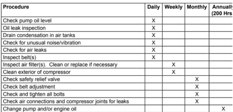
Preventive Maintenance Schedule....................... |
43 |
Service Information............................................... |
44 |
Repairs................................................................. |
44 |
Warranty............................................................... |
44 |
Free Warning Label Replacement........................ |
44 |
Section 6 |
|
Troubleshooting |
|
Troubleshooting.................................................... |
46 |
2
Thank you !
For ordering a JENNY®. Jenny has been a manufacturer of high quality equipment since 1929.
Special attention has been given to every detail of engineering design, perfection of manufacturing methods, individual part inspection, and thorough testing upon completion to assure the continuous trouble-free operation of your Jenny.
In short, your Jenny was designed and made by customer-minded workers. If you, for any reason, fail to find that our product serves as you believe it should, you will be doing yourself and us a favor by telling our Customer Representative, through our Distributor - or direct, just how our product has failed to please you. Over the years we have found that when troubles are reported by our customers, both of us profit. So please help us to serve you properly, which is our first desire.
In the march of progress, engineering and design changes are inevitable, therefore, we reserve the right to vary our designs and/or specifications without implying that they need to be installed on previous models. If you have occasion to order parts or request information about your Jenny, be sure to give machine model number, pump model letter or model number and serial number.
You will find this booklet a valuable guide to the proper and safe operation and maintenance of your new Jenny. It is intended to be used by anyone using or maintaining the equipment. Follow the instructions carefully and you will assure yourself of the utmost in compressed air efficiency and economy.
3
Section 1
Safety and
Health
Instructions
4

Important!
SAFETY AND HEALTH INSTRUCTIONS
FOR SAFE USE
THIS PRODUCT CAN CAUSE SERIOUS INJURY OR
DEATH IF NOT USED IN ACCORDANCE WITH THE FOLLOWING SAFETY INSTRUCTIONS. WE CAN NOT ANTICIPATE EVERY POSSIBLE CIRCUMSTANCE THAT MIGHT INVOLVE A POTENTIAL HAZARD. THE WARNINGS, CAUTIONS, DANGERS, AND SAFETY
SUGGESTIONS ARE THEREFORE NOT ALL INCLUSIVE. AS THE OWNER YOU ARE RESPONSIBLE FOR THE
SAFE OPERATION OF THIS EQUIPMENT. ALWAYS
! DANGER MAKE SURE THAT ANYONE USING THIS EQUIPMENT HAS READ THIS MANUAL AND FOLLOWS THE SAFETY
WARNINGS TO HELP PREVENT THE POSSIBILITY OF PERSONAL INJURY TO THE OPERATOR OR ANYONE ELSE. IF ANY OPERATING PROCEDURE, INSTALLATION, MAINTENANCE, OR WORK METHOD NOT SPECIFICALLY RECOMMENDED IS USED, YOU MUST SATISFY YOURSELF THAT IT IS SAFE FOR YOU AND OTHER PERSONS. YOU MUST ALSO ENSURE THAT THE PRODUCT WILL NOT BE DAMAGED OR MADE UNSAFE BY THE PROCEDURE YOU CHOSE.
In the event that an injury does occur, please seek medical attention at once since the equipment may cause injuries that are not initially recognized.
1. Use proper electrical power.
Connect unit to a dedicated circuit of the proper voltage, proper rated circuit breaker, and wired with the proper wire size and number of conductors.
Use supply Wires suitable for 110°C
Ensure that all connections are properly tightened. Improper connections could result, causing damage, injury, or death of the equipment operator.
This machine must be connected in accordance with the National Electric Code (NEC) Article 422-4 - Ed-31, Except as provided for in NEC 90-4.
This machine must be properly grounded to avoid fatal electrical shock in the event of an electrical malfunction. A ground connector screw should be fastened into the chassis to facilitate supplemental grounding as permitted by NEC 250-91.
5

Do not connect any other equipment to the electrical circuit serving this unit.
Do not replace a fuse or circuit breaker with one of a higher rating without being certain the wire size is adequate to handle the increased electrical load. If connected to a circuit protected by fuses, use time-delay fuse marked “D”.
Keep all electrical connections dry and off of the ground.
Observe all local and national codes for the installation and use of this type of equipment.
Please use the following criteria for wire selection.
•0 to 25 Feet from Main Power Source - At least the same size wire.
•25 to 50 Feet from Main Power Source - At least one wire size larger.
•50 to 100 Feet from Main Power Source - At least two wire sizes larger.
•100 to 150 Feet from Main Power Source - At least three wire sizes larger.
If the wire size being used is too small, the voltage drop will be high, and this will cause the motor to draw excessive current and overheat or fail.
If there are any questions or problems with the electrical system being used please, do not hesitate in calling a local qualified electrician.
2. Wear proper protective clothing and equipment.
Wear full eye protection (preferably a face shield) while operating this product. The pressurized spray from this unit can cause severe injury to the eyes. It also may contain irritants, particles or caustic chemicals.
3. Do not operate with protective covers or guards removed.
Operating this machine with the protective guards or covers removed could expose high speed moving components which could allow the operator or bystander to become entangled. Entanglement in this equipment may result in serious injury, amputation, or death.
This unit may start and stop automatically when switch is in Auto mode.
4. Do not operate with any electrical panels or covers opened.
Operating this unit with any of the electrical panels or covers opened may expose high powered electrical connections and/or components which may come in contact with the operator. Contact with high powered electrical equipment by a person could result in serious injury or death.
5. Do not operate this unit with any of the safety controls bypassed.
This unit was designed with safety in mind. Never allow anyone to bypass, modify, or alter any of the
6

safety devices on this unit. If any of the safety devices appear to be dysfunctional, do not operate the unit and immediately contact a qualified technician.
Periodically have all the safety devices checked for proper operation.
6. Do not operate this unit with any components rated less than the maximum operating pressure of the unit.
This unit was designed to compress air at a specific operating pressure and volume.
Never exceed the pressure rating of air tools, spray guns, air operated accessories, tires, and other inflatables. This can cause them to explode or fly apart and could result in a serious injury.
7. Do not direct air stream at people, animals, or any living thing. Use only OHSA approved air blow guns.
The pressurized spray from this product can cause serious injury or death if sprayed at people, animals, or any living thing. This machine is capable of producing extremely high pressures and/or temperatures. The pressurized spray can cut exposed flesh like a knife. The spray can also cause severe irritation, cuts and/or burns. It can inject air and/or harmful particles and chemicals into the skin and other soft tissues, and this can cause serious injury or death. To prevent this from happening, always hold the air blow gun securely at all times. Never point spray at people, animals, or any living thing.
Never put hands or fingers over the spray tip while in operation. Use only OSHA approved air blow guns.
If an accident occurs and the spray appears to have penetrated the skin, even if the injury appears to be minor, seek medical care immediately. Do not treat as a simple cut. Be prepared to tell a physician what particles and/or chemicals you are using.
For treatment instructions, have your physician contact the nearest regional poison information center for more information.
8. Do not use compressed air from this equipment for breathing.
The compressed air from the compressor is not safe for breathing! The air stream may contain carbon monoxide, toxic vapors, hydrocarbons, oil mist, water vapor, and/or solid particles. Never inhale air from the compressor either directly or from a breathing device connected to the compressor.
9. Unplug or disconnect unit before cleaning or servicing.
To help prevent the risk of injury or death as a result of shock or electrocution or |
entanglement while this product is being cleaned, serviced, or repaired, electrical |
power must be removed. Unplug or disconnect the power cord or “lock out” the switch |
box that supplies power. For more details, please refer to U.S. Department of Labor, |
7

Occupational Safety and Health Administration, Regulation 29 CFR 1910.147, Control of Hazardous
Energy Source (lockout/tagout).
Only qualified personnel should attempt any electrical repairs or trouble shooting on the equipment.
Serious injury or death could result from improper repairs and/or trouble shooting.
10. Never modify or alter this unit.
For your own safety as well as others, never allow this unit to be altered or modified. Modifying or altering equipment to operate in a fashion other than its original design may cause serious injury or death.
Never exceed the factory pressure or temperature rating of the system. Be sure that all accessory equipment and system components meets or exceeds the pressures and temperatures developed by the unit.
11. Do not operate unit with damaged or worn hoses, fittings, clamps, or spuds.
Always check the connection hose, control hoses, fittings, clamps, and spuds prior to operation. Replace all damaged or worn items with one which meets or exceeds the specifications of the original equipment. The use of an improper hose, fitting, clamp, or spud may cause the hose, fitting, clamp, or spud to rupture which could result in serious injury or death or damage to the machine.
12. Do not repair damaged hoses or fittings.
Replace all damaged hoses and/or fittings with ones which meet or exceed the specifications of the original equipment.
Do not use the hose if cuts, leaks, abrasions, bulges, or coupling damage is evident.
Never remove any hose or fitting while the unit is on. The risk of fluid injection is present.
13. Do not touch exposed metal such as the compressor pump, motor, tank, connection hoses, or any fluids.
This unit operates at extremely high temperatures. These temperatures may reach in excess of 240° F. Touching any exposed metal or other surfaces may cause severe burns.
Compressor will remain hot for a long period of time. Allow the compressor to cool to room temperature before attempting any service or repairs.
14. Provide at least three (3) feet of clearance to adjacent construction.
This unit requires adequate ventilation and must be placed in a location which provides at least three feet of clearance to all adjacent construction. This unit operates at high temperatures and failure to
8
allow adequate ventilation or restrict the air flow may cause the machine to overheat or cause materials in close proximity to reach their flash temperatures and ignite.
15. Do not operate near flammable or combustible materials.
This product is not intended for use in locations where fire or explosion hazards may exist due to the presence of flammable vapors, liquids or gases, or combustible dusts  or fibers.
Heat generated by the compression cycle and/or drive system is released into the atmosphere and can cause materials in close proximity to reach their flash temperatures and ignite or explode.
Always operate the compressor in a well ventilated area.
Always store flammable or combustible materials in a secure location away from all open flames, sparks, and heat sources.
16. Do not remove any air line or receiver connections before relieving air pressure in the entire air system and receiver tank(s).
This machine is capable of producing extremely high pressures and/or temperatures. The pressurized spray can cut exposed flesh like a knife. The spray can also cause severe irritation, cuts and/or burns. It can inject air and/or harmful particles and chemicals into the skin and other soft tissues, and this can result in serious injury or death. To prevent this from happening, always relieve the air pressure in the entire system and in the receiver tanks before removing any air lines or receiver connections.
17. Do not operate at pressures, temperatures and rotational speeds in excess of the manufacturers recommendations.
With safety in mind, the unit was designed and is tested to withstand specific operating pressures, temperatures, and volumes. The different components of the machine are matched to produce the factory set operating pressure and volume. Any modification of these settings can cause damage to the compressor and/or maintenance and operating personnel.
Never make adjustments and/or parts substitutions to alter the factory set operating pressures, temperatures, and volumes.
18. Do not spray flammable or toxic liquids in confined areas. Areas must be well ventilated. Follow all manufacturers supplied instructions of the material to be sprayed and the warnings associated with those products.
Never spray flammable liquids in confined areas. The flammable vapors may accumulate and then ignite causing an explosion. Always spray flammable liquids in a well ventilated area free from combustible materials, gasoline, or solvent vapors.
9
Never spray toxic liquids or chemicals in confined areas. The toxic vapors may accumulate and overcome the operator. Injury or death may result.
Read and follow all the safety instructions provided on the product label and Material Safety Data Sheet (MSDS) for the material being used.
Use a NIOSH/MSHA approved respirator designed for use each specific application.
Always wear the appropriate approved safety equipment.
Always operate the compressor in a well ventilated area.
Always store flammable materials in a secure location away from all open flames, sparks, and heat sources.
19. Use this machine only in a well ventilated area.
This unit requires adequate ventilation. Heat generated by the compression cycle of the unit must be released into the atmosphere. Failure to allow adequate ventilation or restrict the air flow may cause the machine to overheat.
20. To prevent corrosion, drain receiver tank(s) after 4 hours of use or at the end of each day, whichever comes first. Have the receiver tank(s) inspected for corrosion and/or damage periodically.
Always drain receiver tanks daily or after each use. If the receiver or any air lines develop leaks, immediately replace them. There is a risk of a violent tank or air line explosion which can cause damage to property and can injure or kill people nearby.
All pressure vessels should be inspected once every year or more often depending on use. To find your state pressure vessel inspector, look under Division of Labor and Industries in the government section of a phone book.
Never make modifications, weld, drill into, or attempt any repairs to compressor tanks.
If modifications are necessary, take the tank to an A.S.M.E. certified coded pressure vessel shop that can perform these modifications. The shop will need an ASME “R” stamp.
Never make adjustments and/or parts substitutions to alter the factory set operating pressures, temperatures, and volumes.
21. Do not use in flammable or combustible atmosphere.
This product is not intended for use in locations where fire or explosion hazards may exist due to the presence of flammable vapors, liquids or gases, or combustible dusts or fibers.
It is normal for the electrical contacts within the motor and the electrical control box to
10

spark. Also, it is normal for gasoline engines to produce extremely high temperatures and sparks. If the high temperatures or sparks from the compressor come in contact with flammable vapors, they may ignite causing a fire or explosion.
22. Do not permit untrained personnel to maintain or make repairs on this unit.
Only qualified personnel should be permitted to make any type of repairs to this unit. Improper repairs may cause this unit to malfunction which could result in serious injury or death to the operator, repair person, or bystander.
23. Risk of Asphyxiation.
The pressurized spray from this unit can cause particles as well as vapors to become airborne. Keep a safe distance from the vapors and airborne particles. Wear protective breathing apparatus and approved safety equipment. Use only in a well ventilated area.
Never use the equipment to spray toxic chemicals. The risk of inhalation or contact with the skin may result in injury or death.
Never attempt to stop or deflect a leak with any part of your body (including the use of a rag). The risk of injection is present.
Some dust may contain chemicals known to the state of California to cause cancer, birth defects, and other reproductive harm. Some of these chemicals are compounds in fertilizers, insecticides, herbicides, pesticides and arsenic and chromium found in treated lumber.
24. Keep compressor as far away from spraying area as possible. At least 25 feet minimum.
When a combustible liquid is sprayed, there can be Danger of Fire or Explosion, especially in and enlosed area.
Do not spray flammable liquids in confined area. Spray area must be ventilated. Do not smoke while spraying or spray where spark or flame is present. Keep compressors as far from spraying area as possible
25. Do not leave loose parts, rags, tools, and other foreign matter on the compressor, drive system, or fan blade.
Loose parts, rags, tools, and other foreign matter can become entangled in the unit or be expelled from the machine at a high rate of speed. This can result in damage to the machine or serious injury or death to the operator, repair person, or bystander.
26. All local code requirements for pressure vessels should be investigated to assure all requirements have been met. Pressure vessels such as the receiver may require additional ASME code stamping to meet local code(s).
11
 Loading...