

Page 1
Product Data Document
420DS-1k
July 16, 2007 - Page 1
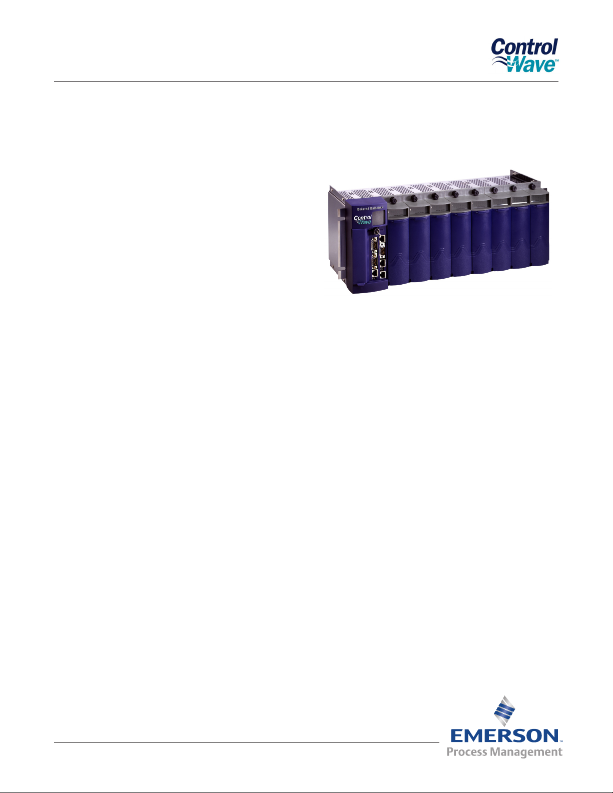
Bristol® ControlWave® PAC
Process Automation Controller
Bristol® ControlWave® PAC, from Emerson Process Management, is a highly adaptable, high
performance Process Automation Controller with
exceptional networking capability to provide a
complete Process Automation Management Solution. Designed with a great emphasis on scalability
and modularity, ControlWave can be congured to
maximize the performance of a wide range of control systems, from small or mid-size applications to
large ones. Additionally, due to its small form factor
and rugged industrial design, ControlWave offers an
outstanding ability to match the requirements of the
most demanding process plant and SCADA system
environments. Above all, Emerson has developed
this innovative controller to provide cost-effective
solutions by minimizing the time required for instal-
lation and conguration.
Through this new open architecture, ControlWave
provides an ideal hybrid union of PLC, RTU and
DCS without compromising the unique features
and capabilities of each product. Consequently, the
ControlWave Process Automation Controller not
only introduces the great possibilities of an open
architecture for emerging communication standards,
but it also provides a simple solution for existing
networks. From its conception, ControlWave was intended as a very exible system capable of satisfying the requirements of local, expanded, remote and
distributed I/O combinations. It is widely accepted
as a scalable platform because it can be used for
small applications using a single rack, but it can
also be expanded to large applications spanning an
entire plant.
Hardware Features
586 based processor provides unparalleled
•
performance
Up to three 100/10 MB Ethernet ports
•
Ethernet remote I/O
•
Up to four serial communication ports
•
2, 4, and 8 I/O slot panel mount chassis, panel
•
or 19” rack mount on 8 slot chassis
Single and double density I/O modules
•
Hot Swap I/O replacement
•
Security key-lock to prevent unauthorized
•
access
Internal loop power for I/O simplies installation
•
AOs maintain last/preset value on CPU
•
Watchdog
Remote Automation Solutions
Website: www.EmersonProcess.com/Remote
DOs maintain last or zero value on CPU
•
Watchdog
Wide temperature range (-40 to +70ºC)
•
Class I, Div. 2 hazardous location and CE
•
approval
Open, industry standards for programming,
•
conguration and communication
Page 2

Product Data Document
420DS-1k
July 16, 2007 - Page 2
Bristol® ControlWave® PAC
Scalability
ControlWave PAC meets the needs of a wide range
of applications, from a unit controller RTU to a
powerful plant process control system through its
modular architecture, large I/O capacity and Ethernet networking capability.
For smaller I/O congurations, the low power
ControlWave Micro and Express are ideal RTU
packages with all of the same software capabilities
of their ControlWave PAC big brother.
ControlWave Micro is a compact modular RTU/PLC
hybrid, providing up to eleven serial communication
ports and optional built-in 100/10 Base-T Ethernet
ports. Built-in spread spectrum radio and dial-line
modem options reduce integration cost, enhance
communication exibility and provide communication back-up.
The base unit is used to house the power system,
CPU and 2 or 6 I/O modules. The base is expandable up to fourteen I/O slots through 2,4 or 8 slot
plug-on I/O expansion bases.
ControlWave Express is a very compact, low prole
SCADA RTU with a xed I/O point count. Extremely
low power consumption makes ControlWave Express highly suitable for many remote sites common
in water, wastewater, and natural gas applications
ControlWave Designer with ACCOL III
To minimize your engineering and development
time, we have adopted the international standard
for PLC programming, IEC 61131-3. ControlWave
Designer is a fully IEC 61131-3 compliant programming environment for the ControlWave family of
products. ControlWave Designer includes all ve
IEC 61131-3 process languages for batch, continuous and discrete control: Function Block Diagram,
Structured Text, Sequential Function Chart, Ladder
Logic Diagram and Instruction List.
ControlWave Designer includes an extensive library
of more than 200 basic IEC 61131-3 functions and
function blocks common to many IEC 61131-3
based products. These include:
Flip-ops, Counters & Timers
•
Ladder diagram functions - coils and contacts,
•
etc.
Numerical, Arithmetic & Boolean functions
•
- Sine, Cosine, Add, Sub, Square Root, And, Or,
etc.
Selection & Comparison - Min, Max, Greater
•
than, Equal, Less than, etc.
Type conversions - Integer to Real, Boolean to
•
Word, etc.
Open Standards for Programming, Net-
work Conguration and Communication
Only ControlWave brings the perfect combination of
industry standards to minimize learning, engineering
and implementation costs.
By adhering to such industry standards as Ethernet,
TCP/IP, Microsoft Windows, COM/DCOM, FTP, OLE
and ActiveX, ControlWave is able to achieve the
highest degree of openness in control system archi-
tecture and bring the optimal process efciency and
productivity needed to ensure a successful system
implementation.
Remote Automation Solutions
Website: www.EmersonProcess.com/Remote
ACCOL III
In addition to the basic functions and function
blocks, ControlWave Designer brings the benet
of over twenty years of SCADA and plant control
experience in Emerson’s Bristol ACCOL III function
block library. ACCOL III includes over sixty func-
tion blocks valuable for use in oil & gas, water and
wastewater and process measurement & control
applications. Further, ACCOL III is designed to take
full advantage of the signicant features offered by
ControlWave.
Briey, this library includes function blocks for:
Average, Compare, Totalize
•
Scheduling & Sequencing
•
Page 3

Product Data Document
420DS-1k
July 16, 2007 - Page 3
PID & Lead/Lag
•
AGA gas ow and liquids calculations
•
File handling
•
In addition, ControlWave ensures data integrity, in
the event of a communication interruption, by storing critical time-stamped alarm and historical data
in the controller memory. This data is then securely
retrieved when communication is restored.
Specications
Bristol® ControlWave® PAC
Ethernet ports with RJ45 connectors
Isolation: Ethernet ports isolated to 500 Vdc
•
Power Supply and Chassis
12 or 24 Vdc power
•
Power-fail detection and recovery sequencer
•
System LEDs for: Active , Fail, & Power OK
•
Power supply isolation: 500 Vdc
•
ISA bus for I/O system (supports Hot Swap I/O)
•
able to drive 8 local chassis I/O modules
CPU
AMD Elan 520 processor: 586 CPU-100 Mhz
•
Data Memory: 2 MB SRAM battery backed
•
memory
Historical Archive memory: Stored in either ash
•
or battery backed SRAM
Code/ Instruction Memory: 16 MB on-board
•
Flash
Synchronous Dynamic memory: 4 MB (66MHz
•
SDRAM coupled to a 32-bit bus)
PCI bus for communication expansion module
•
2-digit ‘Port 80’ display for booting and run-time
•
diagnostics
Key-lock security switch
•
Communication
Two RS-232 serial communication ports with
•
standard PC/AT 9-pin male D-sub connectors
on CPU module, both supporting baud rates up
to 115.2 KB
Two expansion RS 232 or RS 485 serial
•
communication ports: up to 115.2 KB
1 standard PC/AT 9-pin D-sub Connector and 1
RJ45 8-pin connector
Isolation: RS 485 serial communication ports
•
isolated to 500 Vdc
Up to three independent 100/10 Base-T
•
2 – I/O slot chassis: Panel Mount 7.97”W x
•
6.97”H x 4.96”D (202.43W x177.03H x 125.98D)
4 – I/O slot chassis: Panel Mount 11.84”W
•
x 6.97”H x 4.96”D (300.73W x 177.03H x
125.98D)
8 – I/O slot chassis: Panel Mount or 19” Rack
•
Mount 18.96”W x 6.97”H x 4.96”D (481.58W x
177.03H x 125.98D)
Environmental Specications
Industrial operational temperature limits
•
(-40 to + 70oC)
Humidity: 0-95% (non-condensing)
•
Vibration limits: 1.0 g acceleration over 10-150
•
Hz; 0.5 g acceleration over 150-2000 Hz
ControlWave Local I/O
ControlWave ‘Process Friendly’ local I/O modules
are designed to maximize usability while minimizing installation, maintenance, and system downtime
costs. A pull-down door provides front panel wiring
terminal access for technicians. The bezel and even
the terminations can be easily removed from the
I/O card to make wiring even easier. In addition, the
availability of both local direct and remote DIN rail
terminations conveniently accommodates a wide
range of applications.
To minimize eld wiring and eliminate the need for
marshalling strips, the analog input and digital input
modules are capable of supplying loop power to two
Remote Automation Solutions
Website: www.EmersonProcess.com/Remote
Page 4

Product Data Document
420DS-1k
July 16, 2007 - Page 4
Bristol® ControlWave® PAC
wire transmitters and dry contacts. For maximum
channel-to-channel isolation, externally powered
analog and digital inputs may be selected.
Status-at-a-glance indicators offer instant visual
notication of I/O system problems. Each I/O
module has a bi-color Pass/Fail LED to display the
on-line diagnostic status. Digital I/O status LED’s
are provided for each point. Analog Input modules
have a unique feature. Each input point has two
LEDs to indicate input under/over range conditions
due to open and shorted eld devices. The green
LED, when lit, indicates the input is in a normal
range. The Red LED, when lit, indicates the input is
under or over range, typically meaning it is open or
shorted.
Features
Convenient ‘Process Friendly’ pluggable
•
local and remote wiring terminations simplify
installation
Status-at-a-glance LED indicators
•
Single and Double density I/O count available
•
for all modules provide application exibility
Loop powered inputs minimize wiring costs
•
Easy access pull-down door with terminal wiring
•
labels
Hot Swap I/O replacement
•
All I/O modules are enclosed in a rugged
•
aluminum shell
Analog outputs congurable for ‘Hold last value,
•
Fail-Safe state or preset value’
Discrete outputs congurable ‘Hold last value or
•
fail to zero’
Specications
All I/O
Surge protection meets C37.90-1978 and
•
IEC 801-5
Terminations are pluggable and accept a
•
maximum wire size of 14 gauge
‘HOT SWAP’ module replacement is supported.
•
All I/O is frozen for 300 ms when any module is
replaced
Environmental Specications
•
Operating Temperature range: -40 to 70oC
(-40 to 158oF), storage up to 85oC
Relative Humidity: 15-95% non-condensing
Vibration: 1.0g for 10-150 Hz, 0.5g for 150Hz to
2000Hz
RFI Susceptibility: 3V/m – 80 MHz to 1000Mhz
(EN50082-2)
ControlWave Digital Input Module
Number of points: 16 or 32 – non-interrupting
•
inputs
16-bit wide bus access
•
Input Voltage Range: 24 Vdc nominal
•
Remote Automation Solutions
Website: www.EmersonProcess.com/Remote
Input current : 5 mA nominal
•
Optical isolation: 1500 V eld input to logic
•
Surge suppression: 500Vdc MOV to chassis
•
31 Vdc transorb between signal and isolated
ground
Input ltering: 30 ms time constant (contact
•
bounce)
Dry contact or externally powered voltage
•
inputs – 21 Vdc on-board isolated loop power
Page 5

Product Data Document
420DS-1k
July 16, 2007 - Page 5
Bristol® ControlWave® PAC
supply for contacts
Power Consumption: 100 mA max @5V ( all
•
LED’s on)
Status indication: LED per point status and
•
module OK/FAIL LED
ControlWave Digital Output Module
Number of points: 16 or 32
•
16-bit wide bus access
•
Output type: solid state open source MOSFET
•
Operating voltage range: 10 - 31Vdc
•
Maximum operating frequency: 20 Hz
•
Current sink load capability: 500 mA at 31V
•
Electrical isolation: 1500 Vdc
•
Surge supression: 500 MOV to chassis
•
31 Vdc transob between signal and isolated
ground
Status indicator: LED per point status and
•
module OK/FAIL LED
Congurable Fail State ‘OFF’, or ‘Hold Last
•
Value’
Input Impedance: > 1 megOhm for 1-5 Vdc,
•
250 Ohm for 4-20 mA
Common Mode Rejection: 70 db
•
Normal Mode Rejection: 26 db
•
Input Filtering: 300 ms to 99.9% of input signal
•
Channel Settling Time: 680 microseconds
•
Conversion Time: 25 microseconds
•
Accuracy:
•
0.1% of span 25oC
0.2% of span -20 oC to 70 oC
0.3% of span -40 oC to 70 oC
Isolated Voltage Common Mode Range: 31 Vdc
•
to isolated common
LED Indicators : Normal, Over-range/Under-
•
range, module FAIL/OK
On board References: 1V, 5V
•
On-board isolated loop supply for internally
•
powered AI
Surge Supression: 31 Vdc transorb across input
•
signals and (-) input to chassis
500Vdc MOV isolated common to chassis
•
Power consumption: 143 mA max @ 5 Vdc (all
•
LEDs ON)
ControlWave Analog Input Module
Number of Channels: 8 or 16
•
A/D Resolution: 14 bit
•
Input Conguration: Isolated voltage input: 500
•
V per card to chassis 31 V per channel when
externally sourced
Internally or externally sourced current
•
Input:Single-ended inputs 4-20 mA
Voltage Input: Isolated Differential inputs
•
1-5 V dc
Externally sourced current loop with 1–5
•
V input module and 250 ohm resistor
across the input terminals or 4-20 mA
input module
Thermocouple Input Module
Number of Channels: 6 AI
•
Input type: B, R, S, J, E, K, T, C, N, +/- 10 mV
•
AI Resolution: 16 bit
•
Input Conguration: Differential thermocouple
•
Voltage input Impedance: 10 megΩ
•
Channel data acquisition: 50 microsec
•
Conversion Time: 66 millisec for all 6 inputs
•
Input Accuracy: Varies by thermocouple type
•
0.025% of span at 25°C for 10 mV input
0.95% of span -25°C to 70°C for 10 mV input
Common Mode Rejection: 120 db
•
Remote Automation Solutions
Website: www.EmersonProcess.com/Remote
Page 6

Product Data Document
420DS-1k
July 16, 2007 - Page 6
Normal Mode Rejection: 80 db
•
Electrical Isolation: 500 Vdc channel to channel
•
and channel to bus
Surge Suppression: 180 Vdc transorb between
•
signal and ground meets IEEE 472.1978
Cold Junction Compensation: RTD sensor on
•
terminal block
Local or remote terminations
•
Power Consumption - 6 inputs:
•
TC analog input: 0.96 watt
RTD Input Module
Number of Channels: 4 AI
•
Input Type; 2, 3, or 4 wire RTD
•
AI Resolution: 16 bit
•
Voltage Input Impedance: 9.6 KΩ
•
Channel Data Acquisition: 50 microsec
•
Conversion Time: 3 wire - 266 ms, 4 wire - 200
•
ms, for all 4 inputs
Input Accuracy:
•
+/- 0.5°C at 25°C
+/- 1.0°C at -40°C to 70°C
Common Mode Rejection: 120 db
•
Normal Mode Rejection: 80 db
•
Electrical Isolation: 500 Vdc channel to channel
•
and channel to bus
Surge Suppression: 12 Vdc transorb between
•
signal and ground meets IEEE 472.1978
Local or remote terminations
•
Power Consumption - 4 inputs:
•
RTD analog input: 0.6 watt
ControlWave Analog Output Module
Number of Channels: 4 or 8
•
Bristol® ControlWave® PAC
Output congurations: 4-20 mA (650 max. drive)
•
D/A resolution: 12 bit
•
Accuracy:
•
0.1% of span @ 25oC for current output
0.2% of span @ -20 to 70 oC for current output
0.3% of span @ -40 to 70 oC for current output
Electrical Isolation from the power system by an
•
opto-coupler and a dc/dc converter.
Settling time: 1 ms
•
FAIL and OK module status LED
•
Surge Supression: 31 Vdc transorb across
•
output signals and (-) output to common
Power Consumption: 91 mA max. @5 V (all
•
LEDs ON)
500Vdc MOV isolated common to chassis
•
Congurable Output Fail State (hold last value,
•
zero (-5%), to specied value)
ControlWave Universal Digital Input Module and
Counter (UDI)
Number of points: 6 or 12
•
Polled DI and High Speed Counter or Low
•
Speed Counter
Bus Access: 16-bits wide
•
Frequency Range: 0-10 KHz
•
Input Voltage Range: 12V, 24V
•
Debounce circuitry factory set Enabled or
•
Disabled
Input Current: 5mA +/- 10%
•
Each counter input can be congured as a
•
polled input, Low Speed Counter, or High Speed
Counter (Roll-over on 65536, not software
resettable)
Input Filtering, Software congurable for:
•
20 micro seconds for high speed counter
1 milliseconds for low speed counter 30
milliseconds for contact closure interruptible DI
Loop power for dry contact inputs
•
Remote Automation Solutions
Website: www.EmersonProcess.com/Remote
Page 7
Product Data Document
420DS-1k
July 16, 2007 - Page 7
Electrical Isolation: 1500 Vdc to system logic
•
and 500Vdc to chassis
Surge Suppression: 31 Vdc transorb across
•
input and to eld common
Terminations: Pluggable, max wire size is
•
14 gauge. Set, reset, common and Shield
terminals per input
Status Indication: Status LED per input, module
•
PASS/FAIL LED
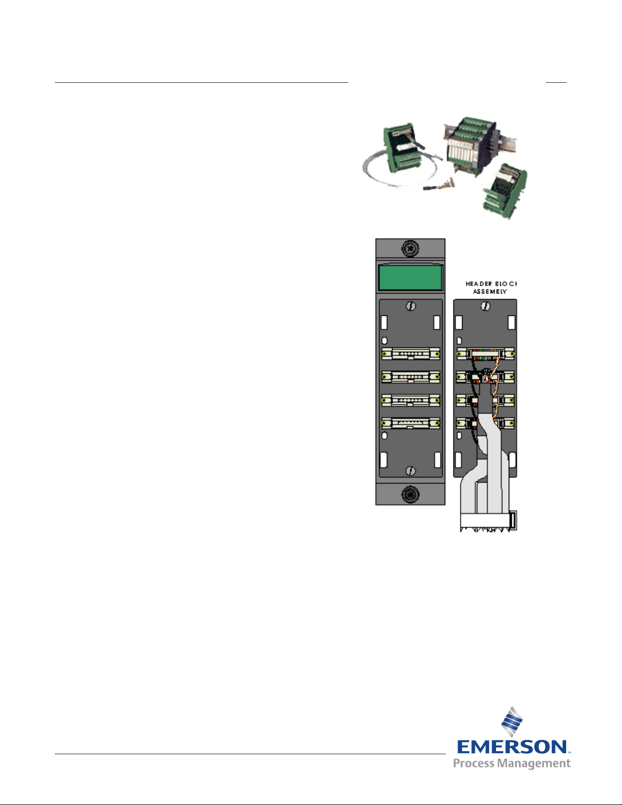
Remote Termination Modules
The remote termination option for ControlWave Local I/O modules provides a convenient alternative
to the standard direct connect termination. Remote
terminiations allow a concentration of electrical connections from one or more controllers to be located
in one area such as the rear of a 19" cabinet.
Bristol® ControlWave® PAC
All Remote Termination modules are standard DINrail mountable and connect to the I/O module with
from one to four pre-wired connector cables. To
simplify installation, all I/O modules use the same
cable.
Features
Removes electrical connections from the
•
controller
Passive terminations are DIN-rail mountable
•
Options for fusing, relays and 120 VAC I/O
•
A single common connector cable for all I/O
•
Up to 14 AWG wire with compression screw
•
terminals
Available Modules
AI: 4 points, no fuses
AI: 4 points, with fuses
AO: 2 points, no fuses
AO: 2 points, with fuses
DI: 24 Vdc - 8 points, no fuses
DI: 24 Vdc - 8 points, with fuses
DI: 120 VAC - 8 points
DO: 24 Vdc - 8 points, no fuse
DO: 24 Vdc - 8 points, with fuse
DO: 8 points - 6 Amp relay
Cable Lengths
18 inch cable
•
39 inch cable
•
6-1/2 foot cable
•
13 foot cable
•
Remote Automation Solutions
Website: www.EmersonProcess.com/Remote
Page 8

Product Data Document
420DS-1k
July 16, 2007 - Page 8
Bristol® ControlWave® PAC
ControlWave I/O Expansion Rack
ControlWave I/O Expansion Racks allow for expansion of I/O up to and including total plant wide
control consisting of hundreds of I/O points. The
process control application program resides in the
main ControlWave process controller. It controls
both local I/O as well as the I/O in the Expansion
Racks. No control functionality is required in the I/O
Expansion Rack.
The ControlWave I/O Expansion Rack consists of
a 2, 4, or 8 slot ControlWave Chassis. The chassis
contains an Ethernet communication engine dedicated to communications between the main processor and the expansion I/O. The communication
engine also supports timing functionality and battery
backed RAM to retain outputs during short power
outages. The ControlWave I/O Expansion Rack is
connected to the main or host ControlWave controller rack via an Ethernet physical link using TCP/IP.
Ethernet is widely accepted as a networking standard physical data link that allows the ControlWave
I/O Expansion Rack to t into any local or wide
area Ethernet based network, thereby increasing
exibility and providing an economical, reliable, I/O
system.
Hardware Features
10/100 Base T Ethernet Interface
•
Serial communications ports for Ethernet port
•
setup
Scalability
ControlWave I/O Expansion Racks allow for in-
creased system exibility depending on the process
I/O count. The expansion racks provide a cost
effective solution to large I/O count projects, and an
economical approach to low or medium I/O count
applications. ControlWave meets the needs of a
wide range of applications.
Specications
Communication Processor
Data Memory: 2 MB SRAM battery backed
•
memory
2-digit “Port 80” display for booting and run-time
•
diagnostics
Communication
Serial communication port with standard PC/AT
•
9-pin male D-sub connector, supporting baud
rates up to 115.2 KB
Isolation: RS-485 communication port isolated
•
to 500 VDC
One 10/100 Base T Ethernet port with RJ-
•
45 connector. (This port is used as the main
communication link to the Host controller.)
Isolation: Ethernet port isolated to 500 VDC
•
2,4, or 8 I/O slot panel mounted stainless steel
•
chassis, panel or 19’ rack mount
Supports all ControlWave I/O modules
•
Hot swap I/O replacement
•
Internal loop power for I/O simplies installation
•
AO’s maintain last/preset value on CPU watch
•
dog
DO’s maintain last or zero value on CPU watch
•
dog
Wide temperature range (-40 to +70 deg. C)
•
Class 1, Div. 2 hazardous location and CE
•
approval
Remote Automation Solutions
Website: www.EmersonProcess.com/Remote
Power Supply and Chassis
12 or 24 VDC power.
•
Power-fail detection and recovery sequencer.
•
System LED’s for: Active, Fail, and Power OK.
•
Power supply isolation: 500 VDC.
•
ISA bus for I/O system (supports Hot Swap I/O)
•
able to drive 8 chassis I/O modules
Chassis dimensions are the same as for the
•
ControlWave PAC
Page 9

Product Data Document
420DS-1k
July 16, 2007 - Page 9
Bristol® ControlWave® PAC
ControlWave Redundancy
Redundant systems are offered for critical processes and harsh applications that require maximum operational readiness and system availability.
ControlWave Redundant Systems are designed to
prevent a single point of failure from shutting down
the system. ControlWave offers two levels of redundant operation in order to achieve the optimum level
of reliability required by the application. Many applications require the level of reliability provided by
the cost effective ControlWave Redundant Process
Control and Communication system. Other, even
more critical applications may require the higher
system availability provided by the ControlWave Redundant I/O system. These designs deliver redundant systems that provide high availability, reliability,
and safety.
ControlWave Redundant System
Dual CPUs, Dual Power Supply Sequencers
•
Automatic Failure Detection
•
Automatic Switchover to Hot Standby Controller
•
Switchover time typically < 500 ms
•
OpenBSI
Simply Creative
Emerson’s OpenBSI (Open Bristol System Interface)
is a set of network setup, communication diagnostic,
and data viewing utilities that provide access to both
Process Control and Communications Redundancy
High Reliability
•
No Single Point of Failure
•
Communication Channel Switching
•
Alarm and Historical Data Backup
•
No programming required for redundancy data
•
transfer
Upgrade programs on the y
•
Convenient Packaging
•
Refer to product data document 420ds11a.pdf for
complete details.
Local I/O or Expansion I/O Redundancy
Remote Automation Solutions
Website: www.EmersonProcess.com/Remote
Page 10

Product Data Document
420DS-1k
July 16, 2007 - Page 10
Bristol® ControlWave® PAC
ControlWave and Network 3000 controllers and
RTUs. OpenBSI is the only product available in the
industry to bring such unique functionality and ease
of use to the network level. At the core is the communication interface, written as a Windows communication server API through which other client
applications communicate with Emerson networks.
OpenBSI supports both serial BSAP protocol
and Ethernet Internet Protocol communication to
ControlWave and Network 3000 RTUs and controllers.
OpenBSI Utilities
Above this communication layer are a group of applications known as OpenBSI Utilities. These client
utilities communicate through the server to collect
and manage data gathered from the network, gen-
Allows network conguration through NetView
•
PC and Network communication diagnostics
•
OPC Server for interfacing to most HMI
•
software
Harvester collects historical data on request or
•
scheduled basis
NetView is the basic conguration and applica-
tion interface for all network operations. NetView
uses a tree structure for network graphical display
in the Windows Explorer style. Network nodes can
be added on-line by simply dragging the node icon
into the tree. This invokes a conguration Wizard,
simplifying network setup. Through the NetView
Wizard, the necessary network parameters are
entered for node and IP address, alarm and message routing, and network communication media.
Once congured, selecting any node allows direct
access to the common OpenBSI utilities to reprogram, download a new application to the node,
review communication statistics, view real-time data
through DataViewer, and edit controller/RTU properties.
erate les based on collected historical data, collect
alarms, and monitor and control OpenBSI communications.
Communication engine for PC applications
•
Supports ControlWave and Network 3000 serial
•
and IP protocols
RS 232, Dial-line, cellular, radio, CDPD,
•
satellite, and Ethernet connections
Provides on-line download & signal variable
•
changes
Remote Automation Solutions
Website: www.EmersonProcess.com/Remote
NetView - Network conguration and ap-
plication LaunchPad
Page 11

Product Data Document
420DS-1k
July 16, 2007 - Page 11
Bristol® ControlWave® PAC
Local Conguration Wizard allows local communication with any attached ControlWave controller
or RTU to download system ashware upgrades,
congure cold download parameters, and congure
IP and soft-switch parameters.
Conguration Wizard simplies network setup
DataView is an on-line utility used to collect and
display several types of process data, including signal values, data array values, signal lists, and audit
trail information.
Operators have the ability to alter signal values.
Multiple DataView windows may be open simultaneously.
WebBSI - WebBSI is a powerful and exible soft-
ware product bringing web technology to all of
Emerson’s Bristol automation and SCADA products.
WebBSI includes a set of ActiveX Controls for reading and writing real-time and historical data, trending, recipe editing and custom display generation.
Through these controls, you can use the standard
Microsoft Internet Explorer web browser to access
Network 3000, TeleFlow and ControlWave products
through a set of supplied HTML web pages.
Custom built web page interface using a
standard web browser
Real-time ActiveX Controls
One of the many benets OpenBSI brings to you is
our use of open standards such as ActiveX Controls. ActiveX is another of the Microsoft standards,
which allow plug and play with any ActiveX container, using Microsoft ActiveX container technology such as Visual Basic, HTML web pages, and
Microsoft Excel.
DataView for Real-time data display
Remote Automation Solutions
Website: www.EmersonProcess.com/Remote
The set of available ActiveX Controls provides the
basic functions necessary to communicate and collect data from ControlWave.
ActiveX Controls
Security 0 56-bit encryption - allows the user to
•
sign on to the RTU
Signal Value - displays signal values in various
•
formats
Page 12

Product Data Document
420DS-1k
July 16, 2007 - Page 12
Comm Statistics - works with a standard page
•
that displays the RTU's communication statistics
Conguration Info - works with a standard page
•
that displays and allows the user to change
RTU conguration information
Historical - Collect and view historical archive
•
and audit les
The IP compliant ControlWave opens the door for
owner controlled access via web pages. Any generic web page builder can be employed to create
user dened pages to access ControlWave. The
web pages are populated with these pre-congured
ActiveX controls.
Bristol® ControlWave® PAC
cal archive in addition to the real-time alarm reporting system.
This le is also collected through OpenBSI and
presented as a text le in the PC. This functionality
is extremely useful in providing an event trail during communication or PC downtime or other sytem
problem.
Archive collection - collection and storage to
•
disk of the ControlWave archive data
Audit collection - collection and storage to disk
•
of the ControlWave audit data
Exports data les to third party, .CSV & ODBC
•
applications
Required Software
Microsoft Internet Explorer
Bristol ActiveX Controls
OpenBSI LocalView or NetView
Historical Data Collection
Historical Data Collection
High Historical Data Integrity
The ControlWave Historical Data Collection system offers exceptional historical data integrity by
providing time-stamped historical data storage in
ControlWave ash memory. The historical data
is collected, through OpenBSI, on a scheduled or
demand basis and converted to .CSV and ODBC
compliant le formats for use in spreadsheets and
reports. If data is missed due to a communication
failure, it is collected when the communications is
re-established and the PC historical database is
backlled with the missing data. This distributed
historical database architecture provides the greatest data reliability and integrity during communication or PC failuer.
Another important historical feature is the Audit
storage and collection system. The Audit Trail is a
les stored in ControlWave ash memory containing
signicant events and time-stamped alarms. The
alarms stored in the Audit system provide a histori-
DDE compliant for use with other popular
•
Windows applications
OPC Server
With industry demand for open standards,
ControlWave answers the call by embracing technologies that open the door for maximizing your
efciency and productivity. The OPC standard was
developed by the OPC Foundation comprised of
hardware and software suppliers from the process
control community. OPC allows the engineer to
select best in class hardware and software with con-
dence in their interoperability. Our OpenBSI OPC
Server was among the rst to comply with the OPC
Foundation alarm and event server specication.
OPC Data Access 1.0a & 2.0 compatible
•
Windows, 2000 & XP
•
Compatible with both ControlWave and Network
•
3000 systems
32 bit multi-threading, multi-processor design
•
Automatic database reader
•
Integrated real-time data monitor
•
Supports OPC Browser interface
•
Supports both serial comm and IP Ethernet
•
connections
Supports COM/DCOM & OLE Automation
•
Remote Automation Solutions
Website: www.EmersonProcess.com/Remote
Page 13

Product Data Document
420DS-1k
July 16, 2007 - Page 13
Primary and Background polling scheme
•
OPC Alarm & Event Server support
•
ControlWave Open Network Connectivity
By embracing the open system network technologies available through TCP/IP, Ethernet, OPC, and
Microsoft DNA, as well as pseudo standards such
as Modbus and Open Modbus, ControlWave can
provide a total Process Automation Management
Solution for in-plant LAN based networks and WIde
Area Network SCADA systems.
With the exceptional connectivity provided by the
ControlWave network, access to real-time data and
operating conditions, historical data, maintenance
and performance data are all available to the global
network. ControlWave provides the needed information to the plant oor technician, operator, engineer, supervisor and corporate management, even
external customers.
Communication Protocols
Like all of Emerson’s products, Bristol ControlWave
supports BSAP (Bristol Standard Asynchronous
Protocol), Modbus, DFI, CIP, DNP3 and serial ASCII
as standard functions. These protocols are implemented in Flashware so no additional hardware
is required to use any one or a combination of all
protocols.
BSAP Protocol
All Emerson’s Bristol Network 3000 and
ControlWave RTU and controller products support
BSAP protocol. BSAP is widely accepted as providing exceptional data integrity and greatly simpli-
es communication between controllers. BSAP is
provided with interfaces for Master/Slave, vertical
networks, and Client/Server, horizontal networks. In
either case, variable lists are created in each controller that are easily passed from server to client or
slave to master.
BSAP meets the denition of an industry-standard,
open architecture protocol because it conforms to
ISO standards 2629, 1745 and 2111, it is not proprietary in that Emerson does not charge a license fee
and makes the protocol and documentation avail-
Bristol® ControlWave® PAC
able to anyone.
While BSAP is an open protocol, the added functionality of the messages provide much more capability than is found in other networks.
Global time-synchronization
•
Time-stamped Alarm reporting
•
Historical archive data transfer
•
Audit le transfer
•
On-line program editing
•
Diagnostics
•
Communication statistics
•
Modbus Protocol
Modbus - Modbus is often considered a de-facto
standard protocol because of its broad usage as
either the primary or a secondary offering in many
measurement and control related products. Even
with its common use, Modbus protocol actually
has many variations. Consider Modbus RTU and
Modbus ASCII, Master & Slave, Serial and TCP/IP
Open Modbus. In addition, there are considerations
regarding supported function codes, oating point
values and byte order. ControlWave supports the
following:
Modbus serial and TCP/IP Open Modbus
•
(Ethernet)
Master and slave
•
Modbus RTU and ASCII
•
Modes 1 - 7, 8, 15 & 16
•
IP modes 51, 52, & 53
•
Integer and IEEE 4 byte oating point
•
Generic Serial Interface
The Generic Serial Interface is a user programmable Master and Slave protocol used to send and
receive messages typically with third party serial
ASCII devices. This protocol can be used to interface with such devices as message boards, card
readers and many measurement devices.
Remote Automation Solutions
Website: www.EmersonProcess.com/Remote
Page 14

Product Data Document
420DS-1k
July 16, 2007 - Page 14
Bristol® ControlWave® PAC
Key-Lock Security
The front panel keyswitch on ControlWave provides
a high level of manual security by allowing three
modes of operation to restrict access ot on-line
functions.
In Run Mode, ControlWave will reject any attempt
to download or modify the running program, either
locally or over the network.
In Remote Mode, ControlWave will allow download-
ing and on-line program modication through the
network provided the security access requirements
have been met. Local download and on-line modication of the running program is prohibited.
In Local Mode, ControlWave will allow download
and on-line modication through either the network
connection or through a local serial communication port provided the security access requirements
have been met.
Multi-User Security Access
Security is an essential element of any open
system, particularly those with Internet access.
ControlWave employs a User Name/Password access system protected by a 56-bit encryption technique through the TCP connection. There can be
up to thirty-two users who sign in using their name
and password. Both the name and the password
can be up to sixteen characters.
The security system provides for up to sixty-four
access rights to read and write data values and les
via FTP, access and congure historical and audit
data information, edit conguration, run internal
diagnostics, read and reset system status. It further
allows the programming software to read, write and
download the ControlWave.
ControlWave was designed to provide the optimum
level of data security using a distributed database
architecture. All data including time & date stamped
alarms, alarm limits, and historical data are stored
locally in each industrially rugged ControlWave,
thereby distributing your data integrity risk. To
rther ensure that the data is always current and
historically accurate, the historical data is stored
in non-volatile ash memory within ControlWave.
Historical data is even maintained during and after
program downloading.
When historical data is collected from ControlWave,
it is converted and appended to .CSV and/or ODBC
compliant databases but does not destroy the original historical data stored in ControlWave, thus pro-
viding a exible and secure historical data system
that is clearly recognized as a benet to virtually
every industrial application.
The Bridge Between Systems
Continuing our tradition of introducing innovative
new solutions while maintaining compatibility with
existing systems, Emerson again provides a migration path for existing customers by bridging the new
ControlWave system with Network 3000 systems
already in place. The network bridge is enabled
by employing the open architecture technologies
afforded by TCP/IP and OPC in both networks.
TCP/IP allows seamless Ethernet connectivity to
both networks as well as the corporate Intranet so
both ControlWave and Network 3000 controllers can
reside and communicate on the same LAN. Emerson’s Bristol OpenBSI OPC Server facilitates the
merging of the two networks for technical, engineering and operator data access. The data source,
conguration and path are completely transparent to
the OPC client. Real-time data can also be passed
between the two communication networks, making
this a total Plant Automation Management Solution.
The Secure Data Advantage
ControlWave sets a new standard for providing intelligent control at the point where control is needed.
Whether you need control on the plant oor or at a
remte site in the "middle of nowhere", ControlWave
is the solution for control, communication and
secure data to help you make the right operating
decisions.
Remote Automation Solutions
Website: www.EmersonProcess.com/Remote
Page 15

Product Data Document
420DS-1k
July 16, 2007 - Page 15
Bristol® ControlWave® PAC
8-I/O Module - ControlWave - Mounting Dimensions
Remote Automation Solutions
Website: www.EmersonProcess.com/Remote
Page 16

Product Data Document
420DS-1k
July 16, 2007 - Page 16
Bristol® ControlWave® PAC
4-I/O Module - ControlWave - Mounting Dimensions
Remote Automation Solutions
Website: www.EmersonProcess.com/Remote
Page 17

Product Data Document
420DS-1k
July 16, 2007 - Page 17
Bristol® ControlWave® PAC
2-I/O Module - ControlWave - Mounting Dimensions
Remote Automation Solutions
Website: www.EmersonProcess.com/Remote
Page 18

Product Data Document
A
B A
4.00
TYP
1.48
2.36
TYP
19 Inch Rack Mount Configuration
For 8 I/O Assembly
C
DETAIL
A
6.71
4.91
1.80
End Panel Mounting
.82
6.98
.28
6.74
.32
.57
ASSEMBLY
DIM.
.32
.46
4 I/O Modules
A
FULL R
8 I/O Modules
.22
FULL R
2 I/O Modules
DIM.
B
18.31
All Dimensions Are In Inches
18.98
DIM.
C
11.65
7.31
10.98
7.98
17.70
6.70
10.37
420DS-1k
July 16, 2007 - Page 18
Bristol® ControlWave® PAC
Remote Automation Solutions
Website: www.EmersonProcess.com/Remote
ControlWave Installation Drawing
Page 19

Product Data Document
420DS-1k
July 16, 2007 - Page 19
Bristol® ControlWave® PAC
ControlWave Base Unit
DESCRIPTION PART NO.
ControlWave main and I/O Expansion rack Chassis (Holds PSSM, CPU and 2, 4, or 8 I/O modules)
Select either the ControlWave CPU or I/O Expansion rack CPU.
0 I/O slot chassis Panel mount 396463-01-0
2 I/O slot chassis Panel mount or 19” rackmount 396356-03-6
4 I/O slot chassis Panel mount or 19” rackmount 396356-02-8
8 I/O slot chassis Panel mount or 19” rackmount 396356-01-0
Internal Power Supply Sequencer Module (PSSM)
12 V input power PSSM 396351-02-6
24 V input power PSSM 396351-01-8
Redundant I/O System
PSSM
24 V input power PSSM used with Redundant I/O system. See Page 5 396351-03-4
CPU (See Note 1) Comm Port Congurations (Note 3)
CPU with 16 MB of RAM 1 - ENET & 2 - RS 232 396359-01-9
CPU with 16 MB of RAM 1 - ENET & 3 - RS 232 & 1 - RS 485 (Note 2) 396359-06-0
CPU with 16 MB of RAM 1 - ENET & 2 - RS 232 & 2 - RS 485 (Note 2) 396359-07-8
CPU with 16 MB of RAM 3 - ENET & 3 - RS 232 & 1 - RS 485 (Note 2) 396359-05-1
CPU with 16 MB of RAM 3 - ENET & 2 - RS 232 & 2 - RS 485 (Note 2) 396359-12-4
I/O Expansion Rack CPU Comm Port Congurations (Note 3)
Comm CPU 2 - RS232 & 1 - ENET 396458-01-7
Comm CPU 1 RS 232, 1 - RS 485 & 1 - ENET 396458-02-5
Remote Automation Solutions
Website: www.EmersonProcess.com/Remote
Page 20

Product Data Document
420DS-1k
July 16, 2007 - Page 20
Bristol® ControlWave® PAC
ControlWave Base Unit (Continued)
DESCRIPTION PART NO.
Local Termination I/O Modules
16 AI 4-20 mA Internally or Externally powered AI 396352-01-4
16 AI 1-5 V & ext. powered 4-20 (with 250 ohm on input) 396352-02-2
8 AI 4-20 mA Internally or Externally powered AI 396352-03-0
8 AI 1-5 V & ext. powered 4-20 (with 250 ohm on input) 396352-04-9
6 TC B, R, S, J, E, K, T, C, N, + 10 mV 396877-01-0
4 RTD 2, 3, or 4 wire platinum RTD 396878-01-6
8 AO 4-20 mA 396353-01-0
8 AO 1-5 V 396353-02-9
4 AO 4-20 mA 396353-03-7
32 DI Selectable Internally or Externally powered Dry Contact 396357-01-6
16 DI Selectable Internally or Externally powered Dry Contact 396357-02-4
32 DO Open Drain - 500 mA current capability, 30 mS lter 396358-01-2
16 DO Open Drain - 500 mA current capability, 30 mS lter 396358-02-0
12 UDI (HighSpeed
Counter) Both 12 and 6 UDI High speed counters come with selectable 396362-01-0
6 UDI (HighSpeed Counter) debounce (enabled/disable) @ (0-10 KHz) Low or High speed 396362-02-8
Notes
Note 1: CE approval requires the CE Accessories kits.
Note 2: RS485 Comm port 3 is RJ45. RS 485 ports have 500 V isolation
Note 3: The I/O Expansion Rack CPU interfaces to the main ControlWave Chassis CPU via Ethernet
Note 4: For conformal coating add -C sufx to each part number.
Remote Automation Solutions
Website: www.EmersonProcess.com/Remote
Page 21

Product Data Document
420DS-1k
July 16, 2007 - Page 21
Bristol® ControlWave® PAC
ControlWave I/O Modules and Termination Blocks
DESCRIPTION PART NO.
Remote Termination I/O Modules (PC 850)
16 AI 4-20 mA Internally or Externally powered AI 396352-11-1
16 AI 1-5 V & ext. powered 4-20 (with 250 ohm on input) 396352-12-0
8 AI 4-20 mA Internally or Externally powered AI 396352-13-8
8 AI 1-5 V & ext. powered 4-20 (with 250 ohm on input) 396352-14-6
6 TC B, R, S, J, E, K, T, C, N, + 10 mV 396877-02-8
4 RTD 2, 3, or 4 wire platinum RTD 396878-02-4
8 AO 4-20 mA 396353-11-8
8 AO 1-5 V 396353-12-6
4 AO 4-20 mA 396353-13-4
32 DI Selectable Internally or Externally powered Dry Contact 396357-11-3
16 DI Selectable Internally or Externally powered Dry Contact 396357-12-1
32 DO Open Drain - 500 mA current capability, 30 mS lter 396358-11-0
16 DO Open Drain - 500 mA current capability, 30 mS lter 396358-12-8
12 UDI (High Speed Counter) Both 12 and 6 UDI High speed counters come with selectable 396362-11-7
6 UDI (High Speed Counter) debounce (enabled/disable) @ (0-10 KHz) Low or High speed
counters. Inputs are 24VDC only.
396362-12-5
Remote Terminal Blocks - (replacement fuses & relays can be found on spares page) (PC 851)
4 point AI (Note 1) No fuse 396391-01-0
4 point AI Fused 396391-02-8
2 point AO (Note 1) No fuse 396391-01-0
2 point AO Fused 396391-02-8
8 point DI No fuse 396292-01-6
8 point DI Fused 395622-02-6
8 point DI - 120 Vac No fuse (for internally powered DI module) 395622-04-2
8 point DI - 120 Vac No fuse (for externally powered DI module) 395622-01-8
8 point DO No fuse 396292-01-6
8 point DO Fused 395622-03-4
8 point DO 6 Amp Relay - No fuse 395622-00-0
3 point UDI No fuse 396391-01-0
3 point UDI (Note 2) No fuse protection 396391-02-8
Remote Automation Solutions
Website: www.EmersonProcess.com/Remote
Page 22

Product Data Document
420DS-1k
July 16, 2007 - Page 22
Bristol® ControlWave® PAC
ControlWave I/O Modules and Termination Blocks (Cont’d)
DESCRIPTION PART NO.
Remote Terminal Blocks (one cable required for each terminal block) (PC 851)
39” Term Cable 396389-01-5
6.5 ft.” Term Cable 396389-02-3
13 ft. Term Cable 396389-03-1
Note 1: Sheild termination connection for AI & AO Remote Terminal blocks 395722-01-2
recommend (P/N 395722-01-2) AO requires one and the AI requires two.
Note 2: Fuses do not offer protection for UDI points.
ControlWave Redundancy
CWREDCPU - A - BC - D
CODE DESCRIPTION CWREDCPU CODE
Redundant unit includes: Chassis, 2-PSSM, 2-CPU, Redundancy Switch Panel and serial
communication cables from the CPUs to the Switch Panel. I/O is located in the Expansion Rack
A Internal Power Supply Sequencer Module A
10 PSSM Power Supply +24 VDC input power 1
PSSM Power Supply +12 VDC input power 2
BC Dual Redundant CPUs Comm Port Congurations CWREDCPUCP BC
20 CPU (2) RS 232, (1) ETHERNET 01
CPU (2) RS 232, (2) RS-485, (1) ETHERNET 07
CPU (2) RS 232, (2) RS-485, (3) ETHERNET 12
D Chassis & Switcher Assembly CWREDCHASI D
30 With Cables, Panel Mount (2) RS-232, (2) RS-485 2
© 2007 Remote Automation Solutions, division of Emerson Process Management. All rights reserved.
Bristol, Inc., Bristol Babcock Ltd, Bristol Canada, BBI SA de CV and the Flow Computer Division , are wholly owned subsidiaries of Emerson Electric Co. doing business as Remote Automation Solutions (“RAS”), a division of Emerson Process Management. FloBoss, ROCLINK, Bristol, Bristol Babcock, ControlWave, TeleFlow and Helicoid are trademarks of RAS. AMS,
PlantWeb and the PlantWeb logo are marks of Emerson Electric Co. The Emerson logo is a trademark and service mark of the Emerson Electric Co. All other marks are property of their
respective owners.
The contents of this publication are presented for informational purposes only. While every effort has been made to ensure informational accuracy, they are not to be construed as warranties or guarantees, express or implied, regarding the products or services described herein or their use or applicability. RAS reserves the right to modify or improve the designs or
specications of such products at any time without notice. All sales are governed by RAS’ terms and conditions which are available upon request. RAS does not assume responsibility for
the selection, use or maintenance of any product. Responsibility for proper selection, use and maintenance of any RAS product remains solely with the purchaser and end-user.
Emerson Process Management
Remote Automation Solutions
Watertown, CT 06795 USA T 1 (860) 945-2200
Mississauga, ON 06795 Canada T 1 (905) 362-0880
Worcester WR3 8YB UK T 44 (1) 905-856950
Website: www.EmersonProcess.com/Remote
 Loading...