

Emerson Process Management BINOS 100 F, BINOS 100 M, BINOS 100, HYDROS 100, BINOS 100 2M User Manual
Page 1

Instruction Manual
ETC00781
February 2004
Series 100 Gas Analyzers
BINOS® 100, BINOS® 100 M
BINOS® 100 2M, BINOS® 100 F
OXYNOS® 100, HYDROS® 100
www.EmersonProcess.com
Software Version 5.1x
Page 2

ESSENTIAL INSTRUCTIONS
READ THIS PAGE BEFORE PROCEEDING!
Emerson Process Management (Rosemount Analytical) designs, manufactures and tests
its products to meet many national and international standards. Because these
instruments are sophisticated technical products, you MUST properly install, use, and
maintain them to ensure they continue to operate within their normal specifications. The
following instructions MUST be adhered to and integrated into your safety program when
installing, using and maintaining Emerson Process Management (Rosemount Analytical)
products. Failure to follow the proper instructions may cause any one of the following
situations to occur: Loss of life; personal injury; property damage; damage to this
instrument; and warranty invalidation.
• Read all instructions prior to installing, operating, and servicing the product.
• If you do not understand any of the instructions, contact your Emerson Process
Management (Rosemount Analytical) representative for clarification.
• Follow all warnings, cautions, and instructions marked on and supplied with the
product.
• Inform and educate your personnel in the proper installation, operation, and
maintenance of the product.
• Install your equipment as specified in the Installation Instructions of the
appropriate Instruction Manual and per applicable local and national codes.
Connect all products to the proper electrical and pressure sources.
• To ensure proper performance, use qualified personnel to install, operate, update,
program, and maintain the product.
• When replacement parts are required, ensure that qualified people use replacement
parts specified by Emerson Process Management (Rosemount Analytical).
Unauthorized parts and procedures can affect the product’s performance, place the
safe operation of your process at risk, and VOID YOUR WARRANTY. Look-alike
substitutions may result in fire, electrical hazards, or improper operation.
• Ensure that all equipment doors are closed and protective covers are in place,
except when maintenance is being performed by qualified persons, to prevent
electrical shock and personal injury.
The information contained in this document is subject to change without notice.
1. Edition: 10/2001 3. Edition: 01/2003
2. Edition: 11/2002 4. Edition: 02/2004
Emerson Process Management
Manufacturing GmbH & Co. OHG
Industriestrasse 1
D-63594 Hasselroth
Germany
T +49 (0) 6055 884-0
F +49 (0) 6055 884-209
Internet: www.EmersonProcess.com
Page 3
SAFETY SUMMARY
GENERAL
Safety Summary
I. Intended Use Statement
The series 100 instruments are intended for use an industrial measurement device only. It is not
intended for use in medical, diagnostic, or life support applications, and no independent agency
certifications or approvals are to be implied as covering such applications.
II. Safety Symbols
Several symbols attached to the analyzer or printed in the instruction manual are used to point
out special sources of danger:
Source of danger !
See Operation Manual!
Electrostatic Discharge (ESD) !
Explosives !
Hot components !
Toxic !
Risk to health !
Analyzer specific notes for the user !
For additional information to these safety symbols see instruction manual.
Strictly follow the related instructions !
ETC00781(4) Series 100 e 02/2004
S - 1
Page 4

SAFETY SUMMARY
GENERAL
III. General
X To avoid explosion, loss of life, personal injury and damages to this equipment and other
property, all personnel authorized to install, operate and service this equipment should be
thoroughly familiar with and strictly follow the instructions in this manual !
Save these instructions !
X If this equipment is used in a manner not specified in these instructions, protective features
may be impaired !
X Correct and safe operation of analyzers calls for appropriate transportation and storage,
expert installation and commissioning as well as correct operation and meticulous
maintenance !
X Emerson Process Management does not take responsibility (liability) for the customer´s
failure to comply with these requirements !
X Do not attempt internal service or adjustment unless other person, capable of rendering first
aid and resuscitation, is present !
X Because of the danger of introducing additional hazards, do not perform any unauthorized
modification to the instrument !
Return the instrument to a Emerson Process Management Sales and Service office for
service or repair to ensure that safety features are maintained !
X Instruments which appear damaged or defective should be made inoperative and secured
against unintended operation until they can be repaired by qualified service personnel.
S - 2
ETC00781(4) Series 100 e 02/2004
Page 5
SAFETY SUMMARY
GENERAL / GASES AND GAS CONDITIONING (SAMPLE HANDLING)
Do not open instrument when energized !
Component replacement and internal adjustments requires servicing by
qualified personnel only !
Read this instruction manual before attempting to operate the instrument !
Be sure to observe the additional notes, safety precautions and warnings
given in the instruction manual !
Operate analyzer as table-top version or as rack-mountable version (built-in) only
(except of BINOS® 100 F: designed for wall mounting only) !
Do not operate the instrument in the presence of flammable gases or explosive
atmosphere without supplementary protective measures !
Hot components may exist at the photometer or in heated versions !
BINOS 100 F
The analyzer has a weight of approx. 30 - 35 kg.
Lift or carry this unit with at least 2 persons.
For easy transport use a suitable cart or comparable tools.
Verify that the cable fittings with installed cables are hermetic to be
in agreement with protection class IP 65 (according to DIN standard 40050).
The permissible outside diameters of the cables are 7 to 12 mm !
The analyzer is intended to be wall mounted. Use bolts which are
suitable for the weight of the unit and appropriate anchors.
ETC00781(4) Series 100 e 02/2004
Make sure the wall where the analyzer is intended to be mounted is solid to
hold the analyzer!
S - 3
Page 6
SAFETY SUMMARY
GASES AND GAS CONDITIONING (SAMPLE HANDLING) / SUPPLY VOLTAGE
IV.Gases and Gas Conditioning (Sample Handling)
Be sure to observe the safety regulations for the gases
(sample gas and test gases / span gases) and the gas bottles !
Inflammable or explosive gas mixtures must not be purged into the instrument
without supplementary protective measures !
To avoid risks for the operators by explosive, toxic or unhealthy gas
components, first purge the gas lines with ambient air or nitrogen (N2) before
cleaning or exchanging parts of the gas paths.
V. Supply Voltage
The socket outlet shall be installed near the equipment and shall be easily
accessible to disconnect the device from the socket outlet.
Verify whether the line voltage stated on the instrument or power supply is in
accordance with that of your mains line!
Be sure to observe the safety precautions and warnings given by
manufacturer of power supply !
X BINOS® 100(M), BINOS® 100 2M (external PS), HYDROS® 100 and OXYNOS® 100 are
Safety Class III instruments.
Verify correct polarity for 24 V DC operation !
S - 4
Use only power supply VSE 2000, UPS 01 T, DP 157, SL5, SL10 (DP 157 and
SL for rack installation only) or equivalent power supplies to keep the
instrument safe.
If using equivalent power supplies they must have SELV output voltage !
ETC00781(4) Series 100 e 02/2004
Page 7
SAFETY SUMMARY
SUPPLY VOLTAGE
X BINOS® 100 2M (internal PS) and BINOS® 100 F are Safety Class 1 instruments
The analyzer is provided with a protective earth terminal.
To prevent shock hazard, the instrument chassis and cabinet must be connected
to an electrical ground. The instrument must be connected to the AC power
supply mains through a three-conductor power cable, with the third wire firmly
connected to an electrical ground (safety ground) at the power outlet.
If the instrument is to be energized via an external power supply, that goes for the
power supply too.
Any interruption of the protective (grounding) conductor or disconnection of the
protective earth terminal will cause a potential shock hazard that could result in
personal injury. Deliberate disconnection is inadmissible / prohibited !
The analyzer BINOS® 100 F (field housing) has no switch with disconnect
function. The customer has to provide a switch or circuit breaker into his
installation. This switch has to be installed near by analyzer, must be easily
attainable for operator and has to be characterized as disconnector for analyzer.
Cables to external data processing have to be double-insulated against mains
voltage for analyzer BINOS® 100 F !
Use cables suitable for intrinsic safe applications only ! Install internal data lines
that they have a distance to mains voltage lines of at least 5 mm.
This distance has to be valid permanently (e.g. via cable holder) !
24 VDC supply to external components/analyzers with the internal power
supply of BINOS® 100 2M requires a fuse to be connected in series to the
consumer which limits the current consumption to max. 2 A !
Verify correct polarity for 24 V DC supply of external components !
ETC00781(4) Series 100 e 02/2004
S - 5
Page 8

SAFETY SUMMARY
ANALYZER SPECIFIC NOTES FOR USER
VI. Analyzer specific notes for the user
The installation site for the instrument has to be dry and remain above
freezing point at all times.
The instrument must be exposed neither to direct sunlight nor to strong
sources of heat. Be sure to observe the permissible ambient temperature !
For outdoor sites, we recommend to install the instrument in a protective
cabinet. At least the instrument has to be protected against rain (e.g., shelter).
Do not interchange gas inlets and gas outlets !
All gases have to be supplied to the analyzer as conditionned gases !
If corrosive gases are inserted into the instrument, it has is to be verified that there
are no gas components which may damage the gas path components.
Ensure that all gas connections are made as labeled and are leak free !
Improper gas connections could result in explosion and death !
The unit´s exhaust may contain hydrocarbons and other toxic gases such as
carbon monoxide ! Carbon monoxide is highly toxic !
Permissible gas pressure of sample gas / test gases max. 1,500 hPa !
The exhaust gas lines have to be mounted in a declining, descending,
pressureless and frost-free and according to the valid emission legislation !
In case it is necessary to open the gas paths, close the analyzers
gas connections with PVC caps immediatly to avoid pollution of gas paths !
BINOS® 100 F lift points are labeled ! Labels showing down side for transport !
Do not use electronics of the optional pressurization system as handle !
S - 6
Use only optional delivered cables from our factory or equivalent shielded cables
to be in agreement with the CE conformity.
The customer has to prove that the shield is connected correctly (chapter 29.10).
Shield and connectors housing have to be connected conductive.
Sub. min. D plugs/sockets have to be screwed to the analyzer.
The analyzer (excepting BINOS® 100 F) is not in agreement with the CE
conformity if optional terminal strip adapters are used In this case CE
conformity must be declared by customer as “manufacturer of system”.
ETC00781(4) Series 100 e 02/2004
Page 9
SAFETY SUMMARY
BINOS® 100 F SPECIFIC NOTES FOR USE IN HAZARDOUS AREAS (EX ZONES)
VII. BINOS® 100 F specific notes for use in hazardous areas (EX Zones)
Be sure to observe the additional notes, safety precautions and warnings
given in the supplemental manual for analyzers intended to be used in
hazardous areas.
If you do not have the additional manual available, please contact your
Emerson Process Management Sales Office!
VII.a Z purge for CSA-C/US Ex Zone 2 Non-Flammable Atmospheres
This enclosure shall not be opened unless the area is known to be free of
flammable materials or unless all devices within have been de-energized !
Upon start-up or after loss of continuous dilution requiring switching off the
electrical supply, purge for 11 minutes with flow rate approx. 55 scfh (26 l/min.,
see chapter 5.3.3) unless the internal atmosphere is known to be well below
the lower explosive limit (LEL) !
This analyzer is not designed for analysis of flammable sample !
Introduction of flammable samples into this equipment could result in explosion,
causing severe personal injury, death or property damage !
Consult factory if flammable samples are to be measured !
Do not open while energized unless it is known that no explosive atmosphere is
present !
ETC00781(4) Series 100 e 02/2004
S - 7
Page 10
SAFETY SUMMARY
Z PURGE FOR CSA-C/US EX ZONE 2 NON-FLAMMABLE ATMOSPHERES
VIII. Additional notes for service / maintenance
Do not open instrument when energized !
Component replacement and internal adjustments requires servicing by
qualified personnel only !
Always disconnect power, discharge circuits and remove external voltage
sources before troubleshooting, repair or replacement of component !
Any work inside the instrument without switching off the power must be
performed by a specialist who is familiar with the related danger, only !
To avoid a danger to the operators by explosive, toxic or unhealthy gas
components, first purge the gas lines with ambient air or nitrogen (N2) before
the gas paths are cleaned or parts are replaced.
Hot components may exist at the photometer or in heated versions !
In case of replacing fuses the customer has to be certain that fuses of specified
type and rated current are used. It is prohibited to use repaired fuses or defective
fuse holders or to short-circuit fuse carriers (fire hazard).
Do not open BINOS® 100 F for use in hazardous areas (EX Zones) while
energized unless it is known that no explosive atmosphere is present !
S - 8
Cleaning of BINOS® 100 F front panel for EX Zone 1:
Danger of electrostatic discharge !
Use damp cloth only for cleaning front panel !
ETC00781(4) Series 100 e 02/2004
Page 11

SAFETY SUMMARY
ADDITIONAL NOTES FOR SERVICE / MAINTENANCE
VIII.a Electrostatic Discharge
The electronic parts of the analyzer can be irreparably damaged if exposed to electrostatic
discharge (ESD).
The instrument is ESD protected when the covers have been secured and safety precautions
observed. When the housing is open, the internal components are not ESD protected anymore.
Although the electronic parts are reasonable safe to handle, you should be aware of the following
considerations:
Best ESD example is when you walked across a carpet and then touched an electrical grounded
metal doorknob. The tiny spark which has jumped is the result of electrostatic discharge (ESD).
You prevent ESD by doing the following:
Remove the charge from your body before opening the housing and maintain during work with
opened housing, that no electrostatic charge can be built up.
Ideally you are opening the housing and working at an ESD protecting workstation.
Here you can wear a wrist trap.
However, if you do not have such a workstation, be sure to do the following procedure exactly:
Discharge the electric charge from your body. Do this by touching a device that is grounded
electrically (any device that has a three - prong plug is grounded electrically when it is plugged
into a power receptacle).
This should be done several times during the operation with opened housing (especially after
leaving the service site because the movement on a low conducting floors or in the air might
cause additional ESDs).
ETC00781(4) Series 100 e 02/2004
S - 9
Page 12

SAFETY SUMMARY
ELECTROSTATIC DISCHARGE
IX. Operating Conditions according to DMT Approval
(The following is a reprint of chapter 6 of the supplement I to the DMT reports
“IBS/PFG-No. 41300392 NIII” and “IBS/PFG-No. 41300292 NIII” about the performance
test of the stationary gas analyzers BINOS
®
100 (M/2M) and OXYNOS® 100).
According to the system version and measuring results included in this report, the stationary
gas analyzers BINOS® 100 (M/2M) from Fisher-Rosemount GmbH & Co. [now: Emerson
Process Management; the editor] are suitable for measuring the concentrations of methane
between 0 and 80 % CH4, of carbon dioxide between 0 and 80 % CO2, of carbon monoxid
between 0 - 200 ppm CO and 0 - 10 Vol.% CO and the stationary gas analyzers BINOS® 100
(M/2M) and OXYNOS® 100 are suitable for measuring of oxygen between 0 - 10 Vol.-%, if the
features and system version go conform with the details contained in the enclosed documents
as stated in this report, if the analysis system is operated accordingly and if the following
requirements are met:
X
When using the gas warning system, it must be ensured that the permissible variations
will not be exceeded, taking into account the systematic failures of the measuring signals
(as indicated in this report) and the local operating conditions. Consider the Code of
Pratice No. T032 of the Labor Association of the Chemical Industry "Usage of stationary
gas warning systems for explosion protection".
X
Verify that the explosion protection requirements are met when using the gas warning
system.
X
Depending on the situation, it must be verified that the preset values are low enough to
allow the system to activate the necessary protection and emergency measures and,
thus, to prevent any critical situations in a minimum period of time.
X
When at system installation, a release of one or both measuring components in the
ambient air might occur, its influence on the measuring result should be proved. A sealed
cell or an external housing purging with sample-free air of measuring gases can be used,
if required.
X
The operability of the alarms and the displays of each system should be tested with clean
air and test gas after the initial operation, after each long-time interruption, and
periodically. The tightness of gas pathes should also be tested. The tests must be
documented by keeping accounts.
S - 10
ETC00781(4) Series 100 e 02/2004
Page 13

SAFETY SUMMARY
OPERATING CONDITIONS ACCORDING TO DMT APPROVAL
X The intervals for the periodical tests must be settled by the person being responsible for
the system´s security and in accordance with the Code of Pratice No. T023 of the Labor
Association of the Chemical Industry "Maintenance of stationary gas warning systems for
explosion protection".
X
Consider the superproportional dependency of the barometric pressure on the
measured value for CO2.
X
The system control with serial interfaces described in this operation manual have not
been subject to this investigation.
X
Sample gas condensation in analyzer (components) must be prevented by taking the
necessary steps.
X
When the system is used with aggressive gases, it is to be verified that there are no gas
components which might damage the gas path components.
X
Appropriate dust filters must precede the used systems.
X
The pressure and flow values recommended by the manufacturer should be observed.
An external monitoring of the sample gas flow through the analyzer should be provided.
X
The results of this investigation are based on the systems using software versions “3.03”,
“4.00”, “4.01” and “4.11”. A change of the software version used must be certified by the
Testing Association.
X
It should be ensured that the system parameters for the analog output have been correctly
adjusted. End of range of low concentration should not be identical or lower than the begin
of range. Disregarding these versions, the measurement range should be adjusted
between 0 to 80 % CH4, 0 to 80 % CO2, 0 to 10 % CO or 0 to 10 % O2 resp. when the systems
are used for explosion protection.
X
Read and follow the operation and maintenance manual supplied to and certified by PFG.
It is important that the temperature is kept between 5 and 45 °C.
ETC00781(4) Series 100 e 02/2004
S - 11
Page 14

SAFETY SUMMARY
OPERATING CONDITIONS ACCORDING TO DMT APPROVAL
X
The analyzer housings must be provided with a permanent type plate indicating the name
of the manufacturer, model number, serial number, and the following reference and date
of testing:
"IBS/PFG-Nr. 41300392" (for CH4, CO2 or CO)
"IBS/PFG-Nr. 41300292" (for O2)
Other designation requirements, such as these according to ElexV, are still valid. With
this type plate, the manufacturer conformes that the features and technical data of the
delivered system are identical with those described in this report. Any system which is not
provided with such a type plate does not go conform with this report.
X
The chapter 6 of this report must be included in the operation and maintenance manual.
X
The manufacturer has to supply the customer with a copy of this report, if required.
X
A print of the report in an abridged version requires the agreement of PFG.
X
The results included in this report may not be altered in publications produced by the
manufacturer.
S - 12
ETC00781(4) Series 100 e 02/2004
Page 15

SAFETY SUMMARY
OPERATING CONDITIONS ACCORDING TO DMT APPROVAL
ETC00781(4) Series 100 e 02/2004
S - 13
Page 16

SAFETY SUMMARY
S - 14
ETC00781(4) Series 100 e 02/2004
Page 17

PREFACE
PREFACE
General Overview
The series 100 of analyzers offers multi-component, multi-method analysis. Different measurement methods can be combined in one analyzer. The following measuring methods of the
individual measuring channels are possible:
IR = non-dispersive infrared measurement
PO2= paramagnetic oxygen measurement
EO2= electrochemical oxygen measurement
TC = thermal conductivity measurement
All analyzers are designed to measure 1 or 2 gas components except of HYDROS® 100 and
OXYNOS® 100 in case of PO2 measurement (both 1 channel only).
a) Software Versions
Different software versions and analyzer options are available:
BINOS® 100 (M), OXYNOS® 100, HYDROS® 100 (1/4 19" housing, external power supply):
Version 4.11 with optional RS 232/485 Interface (according to DMT Approval)
Version 5.10 with optional RS 232/485 Interface
BINOS® 100 2M (1/2 19" housing, internal power supply):
Version 4.11 with optional RS 232/485 Interface (according to DMT Approval)
Version 5.10 with optional RS 232/485 Interface
*)
BINOS® 100 2M (1/2 19" housing, external power supply):
Version 4.11 with optional RS 232/485 Interface (according to DMT Approval)
Version 5.10 with optional RS 232/485 Interface*) and/or with optional 7 digital inputs
Version 5.11 with optional 7 digital inputs and FOUNDATION™ Fieldbus
**)
BINOS® 100 F (field housing, internal power supply):
Version 4.11 with optional RS 232/485 Interface (according to DMT Approval)
Version 5.10 with optional RS 232/485 Interface*) and/or with optional 7 digital inputs
Version 5.11 with optional 7 digital inputs and optional FOUNDATION™ Fieldbus
*)
not in combination with FOUNDATION™ Fieldbus
**)
not in combination with RS 232/485 interface
ETC00781(4) Series 100 e 02/2004
**)
P - 1
Page 18

PREFACE
b) Housing Versions
Different housing versions are delivered (for detailed informations see price list):
BINOS® 100 = 1/4 19" housing, ext. PS one or two IR channel
BINOS® 100 M = 1/4 19" housing, ext. PS, one IR channel and one EO2 channel
BINOS® 100 2M = 1/2 19" housing, one or two IR channel(s) or
internal or external PS, one IR channel and one EO2 channel or
one IR channel and one PO2 channel or
one IR channel and one TC channel or
one PO2 channel and one TC channel or
one EO2 channel and one TC channel or
one ot two PO2 channels
one ot two EO2 channels
one or two TC channels
with standard options: one internal sample gas pump
one internal solenoid valve block
one integrated fine dust filter
one integrated flow indicator
BINOS® 100 F = field housing, int. PS, measuring channels see BINOS® 100 2M
with standard options: see BINOS® 100 2M (dust filter for GP only)
HYDROS® 100 = 1/4 19" housing, ext. PS, one TC channel
OXYNOS® 100 = 1/4 19" housing, ext. PS, one or two EO2 channel or
one PO2 channel
P - 2
ETC00781(4) Series 100 e 02/2004
Page 19

PREFACE
Area Classification
a) General Purpose
All analyzer components are installed into a 1/4 19" housing (BINOS® 100 (M), OXYNOS® 100,
HYDROS® 100) or a 1/2 19" enclosure (BINOS® 100 2M), 3 height units. These housings are go
conform to DIN-standard protection class IP 20. The housings are available as rack-mountable
or as table-top versions. The table-top housings are fitted with an additional carrying handle and
additional rubber feets.
Additionally we can deliver a field housing version (BINOS® 100 F). All componets are installed
into a protection housing conforming to DIN-standard protection class IP 65 (approx. NEMA 4/4X).
This enclosure is designed for wall mounting.
b) Hazardous Areas
For installation in hazardous areas special versions of BINOS® 100 F are avaliable with
adapted options and specifications. These versions are not subject of this manual (except the
variation with Z-purge). For all other analyzer versions intended to be used in hazardous areas
pls. refer to the separate manuals.
Ex Zone 2
The BINOS® 100 F is equipped with
- Pressurization system for ATEX EX Zone 2 Applications
- Z purge for CSA-C/US EX Zone 2 Non-Flammable Atmospheres
Ex Zone 1
The BINOS® 100 F is equipped with
- Pressurization system for ATEX EX Zone 1 Applications
ETC00781(4) Series 100 e 02/2004
P - 3
Page 20

PREFACE
P - 4
ETC00781(4) Series 100 e 02/2004
Page 21

CONTENTS
Table of Contents
SAFETY SUMMARY S - 1
I. Intended Use Statement S - 1
II. Safety Symbols S - 1
III. General S - 2
V. Supply Voltage S - 4
VI. Analyzer specific notes for the user S - 6
VII. BINOS® 100 F specific notes for use in hazardous areas (EX Zones) S - 7
VII.a Z purge for CSA-C/US Ex Zone 2 Non-Flammable Atmospheres S - 7
VIII. Additional notes for service / maintenance S - 8
VIIIa Electrostatic Discharge S - 9
IX. Operating Conditions according to DMT Approval S - 10
PREFACE P - 1
General Overview P - 1
a) Software Versions P - 1
b) Housing Versions P - 2
Area Classification P - 3
a) General Purpose P - 3
b) Hazardous Areas P - 3
Ex Zone 2 P - 3
Ex Zone 1 P - 3
1. TECHNICAL DESCRIPTION 1 - 1
1.1 Front Panel 1 - 1
1.2 Rear Panel 1 - 5
1.3 Internal Construction 1 - 11
1.3.1 Internal Gas Paths 1 - 25
a) Gas Path Material 1 - 25
b) Gas Path Layout (internal tubing) 1 - 26
ETC00781(4) Series 100 e 02/2004
I
Page 22

CONTENTS
2. MEASURING PRINCIPLE 2 - 1
2.1 IR Measurement 2 - 1
2.1.1 Interference Filter Correlation (IFC Principle) 2 - 1
2.1.2 Opto-Pneumatic Measuring Principle 2 - 3
2.1.3 Technique 2 - 5
2.2 Oxygen Measurement 2 - 6
2.2.1 Paramagnetic Measurement 2 - 6
2.2.2 Electrochemical Measurement 2 - 8
2.3 Thermal Conductivity Measurement 2 - 10
2.3.1 Sensor Design 2 - 10
2.3.2 Analysis Cell 2 - 10
2.3.3 Measurement Method 2 - 11
3. PHOTOMETER ASSEMBLY 3 - 1
3.1 Photometer with Pyroelectrical Detector (Solid-state detector) 3 - 1
3.2 Photometer with Gas Detector 3 - 4
5. PREPARATION OF START-UP 5 - 1
5.1 Installation Site 5 - 2
5.2 Gas Conditioning (Sample Handling) 5 - 3
5.2.1 Fine Dust Filter (Option BINOS® 100 2M/F) 5 - 4
5.2.2 Gas Sampling Pump (Option BINOS® 100 2M/F) 5 - 4
5.2.3 Pressure Sensor (Option) 5 - 4
5.2.4 Gas Flow 5 - 4
5.3 Gas Connections 5 - 5
5.3.1 Standard 5 - 5
5.3.2 Internal Solenoid Valves (Option BINOS® 100 2M/F) 5 - 8
5.3.3 Purge gas connection of BINOS® 100 F for Ex zones 5 - 10
5.4 Additional Hints to BINOS® 100 F (Field Housing) 5 - 11
5.4.1 Wall Mounting 5 - 12
5.4.2 Electrical Connections 5 - 13
II
ETC00781(4) Series 100 e 02/2004
Page 23

CONTENTS
6. SWITCHING ON 6 - 1
6.1 General 6 - 1
6.2 24 V DC Supply 6 - 2
6.3 230/120 V AC Supply 6 - 2
6.3.1 BINOS® 100 2M 6 - 4
6.3.2 BINOS® 100 F 6 - 5
7. KEY FUNCTIONS 7 - 1
7.1 FUNCTION 7 - 2
7.2 ENTER 7 - 4
7.3 INPUT - CONTROL 7 - 6
7.4 PUMP (BINOS® 100 2M/F only) 7 - 7
8. SETTING SYSTEM PARAMETERS 8 - 1
8.1 Pressure Correction 8 - 2
8.2 Cross Compensation (internal) 8 - 2
8.3 Cross Compensation Calibration (internal) 8 - 3
8.4 Hold 8 - 4
8.5 Automatic Calibration 8 - 4
8.6 Tolerance Check 8 - 5
8.7 Display Off 8 - 6
8.8 Analog Signal Outputs 8 - 7
8.9 Flushing Period 8 - 8
8.10 User Code 8 - 8
8.11 Response Time (t90) 8 - 9
8.12 Offset (Begin of range) 8 - 10
8.13 End of Range Value 8 - 11
8.14 Reset 8 - 12
8.15 Program Version 8 - 13
8.16 Serial - No. 8 - 13
8.17 Pump *) 8 - 14
8.18 Pump Control *) 8 - 14
ETC00781(4) Series 100 e 02/2004
III
Page 24

CONTENTS
9. CALIBRATION 9 - 1
9.1 Manual Calibration 9 - 2
9.1.1 Zeroing 9 - 2
9.1.2 Spanning 9 - 4
9.2 Time-Controlled Calibration Mode (Option) 9 - 7
9.2.1 Zeroing 9 - 7
9.2.2 Combined Zeroing and Spanning 9 - 9
9.3 Remote-Controlled Calibration Mode (Option) 9 - 10
10. MEASUREMENT / SWITCHING OFF 10 - 1
10.1 Measurement 10 - 1
10.2 Switching Off 10 - 1
11. DIGITAL OUTPUTS 11 - 1
11.1 Concentration Limits 11 - 2
11.2 Valve Control 11 - 4
11.3 Status Signals (Option non-voltage-carrying relay contacts) 11 - 4
12. SERIAL INTERFACE (OPTION) 12 - 1
12.1 Upgrading Serial Interface / Status Signals 12 - 1
12.2 General 12 - 2
12.3 Start Up 12 - 4
12.3.1 RS 232 C 12 - 4
12.3.2 RS 485 12 - 5
12.3.3 Switching ON/OFF Interface Operation 12 - 6
12.3.4 Setting Interface Parameters 12 - 6
12.4 Telegram Syntax 12 - 8
12.4.1 Start Character ( “$” = Hex 24) 12 - 8
12.4.2 Terminate Character ( “CR” = Hex OD) 12 - 8
12.4.3 Instruction Code 12 - 8
12.4.4 Hyphen Character ( “;” = Hex 3B) 12 - 8
12.4.5 Status Telegram 12 - 9
12.4.6 Numerical Representations 12 - 10
12.4.7 Block Parity Check 12 - 10
12.5 Instruction Syntax 12 - 11
12.5.1 Instruction Listing 12 - 12
12.5.2 Response Telegrams 12 - 13
IV
ETC00781(4) Series 100 e 02/2004
Page 25

CONTENTS
13. DIGITAL INPUTS / FOUNDATION™ FIELDBUS
(BINOS® 100 2M/F OPTION ONLY) 13 - 1
13.1 Digital Inputs 13 - 1
13.1.1 General 13 - 1
13.1.2 Start of Calibration 13 - 1
13.1.3 Valve Control 13 - 2
13.1.4 Pump Control 13 - 2
13.2 Foundation™ Fieldbus *) 13 - 2
14. CROSS COMPENSATION / SETTING OF RESPSONSE TIME
(TC OPTION ONLY) 14 - 1
14.1 Cross Compensation 14 - 1
14.1.1 Preparing Actions 14 - 2
14.1.2 Adjustment Procedure 14 - 3
16. LIST OF FAILURES 16 - 1
17. MEASURING POINTS OF BKS AND OXS 17 - 1
17.1 Measuring points of BKS 17 - 1
17.1.1 Supply Voltage + 6 V 17 - 1
17.1.2 Reference Voltage positive 17 - 1
17.1.4 Motor Drive (for IR channel only) 17 - 2
17.1.5 Temperature Sensor 17 - 3
17.1.6 Light Barrier Signal 17 - 4
17.1.7 Analog Preamplifiering 17 - 5
17.2 Measuring points of OXS (EO2 measurement) 17 - 6
17.2.1 Sensor Signal 17 - 6
ETC00781(4) Series 100 e 02/2004
V
Page 26

CONTENTS
18. PLUG PIN ALLOCATION OF PRINTED CIRCUIT BOARDS 18 - 1
18.1 Plug Pin Allocation of BKS 18 - 1
18.1.1 IR measurement without oxygen channel 18 - 2
18.1.2 Oxygen Measurement without IR channel 18 - 2
18.1.3 IR / Oxygen Measurement combined 18 - 3
18.1.4 TC Measurement without IR channel 18 - 3
18.1.5 IR / TC Measurement combined 18 - 4
18.1.6 Oxygen / TC Measurement combined 18 - 4
18.2 Plug Pin Allocation OXS (EO2 measurement only) 18 - 5
18.3 Plug Pin Allocation WAP 100 (TC measurement only) 18 - 6
19. JUMPER ALLOCATION OF BKS 19 - 1
21. FINE DUST FILTER (OPTION) 21 - 1
22. LEAK TESTING 22 - 1
23. HOUSING 23 - 1
23.1 Cleaning of Housing Surface 23 - 1
23.2 Opening the Housing 23 - 2
23.2.1 1/4 19" Housing 23 - 2
23.2.2 BINOS® 100 2M 23 - 3
a) Housing Cover 23 - 3
b) Front Panel 23 - 4
23.2.3 BINOS® 100 F (Field Housing) 23 - 5
24. REPLACEMENT AND CLEANING OF PHOTOMETRIC
COMPONENTS 24 - 1
24.1 Taking out the Photometer Assembly 24 - 1
24.2 Light Source Replacement 24 - 2
24.3 Cleaning of Analysis Cells and Windows 24 - 3
24.3.1 Removal of Analysis Cells 24 - 3
24.3.2 Cleaning 24 - 4
24.3.3 Reinstalling the Analysis Cells 24 - 5
24.4 Chopper Replacement 24 - 6
24.5 Reinstalling of the Photometer Assembly 24 - 6
24.6 Physical Zeroing 24 - 7
24.6.1 Standard Photometer (not sealed version) 24 - 7
VI
ETC00781(4) Series 100 e 02/2004
Page 27

CONTENTS
24.6.2 Sealed Photometer (Option) 24 - 8
25. CHECKING / REPLACING AN ELECTROCHEMICAL
OXYGEN SENSOR 25 - 1
25.1 Checking the Sensor 25 - 2
25.2 Replacing the Sensor 25 - 3
25.2.1 Remove the old Sensor 25 - 3
a) Oxygen Measurement without IR - channel 25 - 3
b) IR / Oxygen Measurement combined 25 - 5
25.2.2 Removing the Sensor 25 - 6
25.2.3 Reinstalling the Sensor 25 - 6
a) Oxygen Measurement without IR - channel 25 - 6
b) Combined IR / Oxygen Measurement 25 - 6
25.2.4 Basic settings for the Oxygen Sensor 25 - 7
27. TECHNICAL DATA 27 - 1
27.1 Options 27 - 1
27.2 Housing 27 - 1
27.3 Signal Inputs / Outputs, Interfaces 27 - 2
27.4 General Specifications 27 - 3
27.5 Voltage Supply 27 - 9
27.5.1 Electrical Safety 27 - 9
27.5.2 Power Supplies [UPS 01 T / SL10 / SL5] 27 - 9
28. REPLACING THE EPROM 28 - 1
30. CABLES AND CORDS 30 - 1
30.1 24 V DC Supply Cable 30 - 1
30.2 230/120 V AC Input (BINOS® 100 2M, UPS power supply) 30 - 2
30.3 Power Supply for Wall Mounted Analyzers (BINOS® 100 F) 30 - 2
30.3 Data / Signal Lines 30 - 3
30.3.1 Sub D Sockets, 9 pin 30 - 3
30.3.2 Sub D Plugs, 9 pin 30 - 3
32. FAILURE CHECK LIST 32 - 1
a) Customer Service 32 - 4
b) Training 32 - 4
ETC00781(4) Series 100 e 02/2004
VII
Page 28

CONTENTS
VIII
ETC00781(4) Series 100 e 02/2004
Page 29

CONTENTS
ETC00781(4) Series 100 e 02/2004
IX
Page 30

CONTENTS
X
ETC00781(4) Series 100 e 02/2004
Page 31

TECHNICAL DESCRIPTION
FRONT VIEW
1. Technical Description
The different analyzers are based on the same internal main components and differ only by
available options and enclosures.
BINOS® 100 (M), OXYNOS® 100, HYDROS® 100 (1/4 19" enclosures)
BINOS® 100 2M (1/2 19" enclosure )
All analyzer components are installed into enclosure, 3 height units tall. These housings are
classified protection class IP 20. The housings are available as rack-mountable or as table-top
versions. The table-top housings are fitted with an additional carrying handle and additional
rubber feets.
BINOS® 100 F (field housing, wall mountable)
Additional we can deliver a field housing version . All components are installed into a protective
enclosure, classified IP 65 acc. IEC 60529 (approx. NEMA 4/4X). This enclosure is designed
for wall mounting. An magnetically operated impact tested front panel is available as an option.
Special versions are available for installation in hazardous areas, which meet the
requirements of either ATEX (Europe), CENELEC (outside Europe) or North America
(CSA-C/US; Z-purge).
The special conditions for operating ATEX analyzers are described in a supplemental manual.
1.1 Front Panel
The front panel includes the LED displays for both analysis channels and all of the analyzer
operating controls.
The BINOS® 100 2M and BINOS® 100 F front panels show status LEDs for the options
“Solenoid Valves” and “Gas Sampling Pump” and include a key “PUMP” *) to switch on and off
the gas sampling pump.
The front panels of BINOS® 100 2M and BINOS® 100 F may be equipped with an optional fine
dust filter with integrated needle valve or/and a flow meter (for general purpose applications
only).
These options are not available if BINOS® 100 F is intended to be used in hazardous areas (EX
Zones) or if IP 65 is required.
ETC00781(4) Series 100 e 02/2004
1 - 1
Page 32

TECHNICAL DESCRIPTION
FRONT VIEW
1
11
12
250 ppm
CO
% O
para. oxygen sensor
% O
2
FUNCTION ENTER INPUT - CONTROL
2
chem.
% O
chem. oxygen sensor
7
paramagnetic
2
electrochemical
2
4
65
1 - 2
Fig. 1-1: BINOS® 100 (M), OXYNOS® 100, HYDROS® 100 Front view
1 LED display (channel 1)
2 LED display (channel 2)
4 Input setting control key DOWN
5 Input setting control key UP
6 Key ENTER
7 Key FUNCTION
11 Fastening screws for the carrying-strap bracket
or rack-mounting purposes
12 Housing cover fastening screw
ETC00781(4) Series 100 e 02/2004
Page 33

TECHNICAL DESCRIPTION
FRONT VIEW
Needle valve (option)
³
12
% O
2
1000
ppm
45678391011
Fig. 1-2: BINOS® 100 2M (standard version), front view
1 LED display (channel 1)
2 LED display (channel 2)
3 Function LED for options "Solenoid Valves / Gas Sampling Pump"
4 Input setting control key DOWN
5 Input setting control key UP
6 ENTER key
7 FUNCTION key
8 Key for option “Gas Sampling Pump”
9 Flow indicator (option)
10 Fine dust view filter with needle valve (option)
11 Fastening screws for the carrying strap bracket
or rack-mounting purposes
ETC00781(4) Series 100 e 02/2004
1 - 3
Page 34

TECHNICAL DESCRIPTION
FRONT VIEW
Wall mounting
holder
Fastener
front panel
Fig. 1-2 for
General Purpose
Operation front panel
Fig. 1-4 for
hazardous areas
(ex zones)
Fig. 1-3: BINOS® 100 F, front view
Front panel
1 - 4
Fig. 1-4: BINOS® 100 F magnetically operated front panel , impact tested, front view
ETC00781(4) Series 100 e 02/2004
Page 35

1.2 Rear Panel
The rear panels include
R the gas line fittings
R the plug for the electrical supply input
R the subminiature “D” mating socket for the analog signal outputs
TECHNICAL DESCRIPTION
REAR PANEL
R the subminiature “D” plug for the digital outputs (concentration limits / valve control)
R optionally the subminiature “D” mating plug for analog signal inputs
(interference cross compensation, TC only)
R optionally the subminiature “D” mating socket for the RS 232 C / RS 485 interface
R optionally the subminiature “D” mating plug for the status signals (relay outputs)
For BINOS® 100 2M/F only:
R optionally the solenoid valve block
R optionally the terminal strips for the 7 digital inputs
R optionally the terminal strips for the FOUNDATION™ Fieldbus
**)
**) ***)
*)
*)
not in combination with FOUNDATION™ Fieldbus
**)
BINOS® 100 2M with external power supply only
***)
not in combination with RS 232/485 interface
ETC00781(4) Series 100 e 02/2004
1 - 5
Page 36

TECHNICAL DESCRIPTION
REAR PANEL
K1 K2 K1 K2
1
IN
OUT
CROSS COMP.
6
5
8
X1 OUTPUT
7
INTERFACE
24 V
max. W
X2 OUTPUT
3
12+ 1
X3 OUTPUT
2
MADE I N GERMANY
9
4
1 - 6
3
Fig. 1-5: BINOS® 100 (M), OXYNOS® 100 (EO2), HYDROS® 100, Rear view
1 Gas inlet line fittings
2 Analog signal output mating socket
3 24 VDC supply input terminal
4 Plug for Digital signal output
5 Gas outlet line fittings
6 Housing cover fastening screws
7 mating socket Serial Interface [RS 232 C / 485] (Option)
8 Plug for Output Relays (Option)
9 Plug for analog signal inputs
(interference cross compensation, HYDROS® 100 only)
ETC00781(4) Series 100 e 02/2004
Page 37

TECHNICAL DESCRIPTION
REAR PANEL
X2 OUTPUT
7
INTERFACE
X1 OUTPUT
6
IN
1
2
8
3
24 V
max. 40 W
3
12+1
OUT
5
4
X3 OUTPUT
MADE I N GERMANY
ETC00781(4) Series 100 e 02/2004
Fig. 1-6: OXYNOS® 100 (PO2), Rear view
1 Gas inlet line fittings
2 Analog signal output mating socket
3 24 VDC supply input terminal
4 Plug for Digital signal output
5 Gas outlet line fittings
6 Housing cover fastening screws
7 mating socket Serial Interface [RS 232 C / 485] (Option)
8 Plug for Output Relays (Option)
1 - 7
Page 38

TECHNICAL DESCRIPTION
REAR PANEL
12 34 56789
17
FLOW
10
11
Fig. 1-7: BINOS
15
®
100 2M, version A (shown with internal power supply), Rear view with all options
12131416
1 Gas inlet line fitting
22
nd
gas inlet line fitting (option)
3 Gas outlet line fitting
42
nd
gas outlet line fitting (option)
5 Plug for analog signal inputs
(interference cross compensation, TC only)
6 “Solenoid valves”: common gas outlet line fitting
7 “Solenoid valves”: Test gas inlet 1
8 “Solenoid valves”: Test gas inlet 2
9 24 VDC output (max. 2 A, see technical data)
10 Power supply [UPS 01 T (Universal Power Supply)]
11 Plug Power Supply (Mains line)
12 “Solenoid valves”: Zero gas inlet
13 “Solenoid valves”: Sample gas inlet
14 Plug Digital Outputs (threshold contacts)
15 Mating socket Serial Interface [RS 232 C / 485] (option)
16 Mating socket Analog Signal Outputs
17 Plug Output Relays (status signal option)
1 - 8
ETC00781(4) Series 100 e 02/2004
Page 39

TECHNICAL DESCRIPTION
REAR PANEL
1234 5
K1 K2 K1 K2
IN OUT
X1 OUTPUT
FLOW
IN/OUT
X2 OUTPUT X3 OUTPUT
DURCHFLUSS
MAX. 1 L/ MIN
87
ANALOG I N
SPAN 1
SPAN 2
SAMPLE
ZERO
1
3
OUT
2
24V
max.120W
9
DIGI TAL IN
V+
V-
E1
E2
E3
E4
E5
E6
E7
FB+
FBFB+
FB-
16 15 17 14 13 12
Fig. 1-8: BINOS
®
100 2M, version B (with external power supply), Rear view with all options
6
1 Gas inlet line fitting
22
nd
gas inlet line fitting (option)
3 Gas outlet line fitting
42
nd
gas outlet line fitting (option)
5 Plug for analog signal inputs
(interference cross compensation, TC only)
6 “Solenoid valves”: common gas outlet line fitting
7 “Solenoid valves”: Test gas inlet 1
8 “Solenoid valves”: Test gas inlet 2
9 Terminal strips for the 7 Digital Inputs (option)
10 Terminal strips for FOUNDATION™ Fieldbus (option)
11 24 V DC supply input terminal
12 “Solenoid valves”: Zero gas inlet
13 “Solenoid valves”: Sample gas inlet
14 Plug Digital Outputs (threshold contacts)
15 Mating socket Serial Interface
16 Mating socket Analog Signal Outputs
17 Plug Output Relays (status signal option)
*)
**)
[RS 232 C / 485] (option)
1011
ETC00781(4) Series 100 e 02/2004
*)
only possible if serial interface RS 232/485 is not request !
**)
only possible if FOUNDATION™ Fieldbus is not request !
1 - 9
Page 40

TECHNICAL DESCRIPTION
REAR PANEL
1234 5
OUTIN
X1 OUTPUT
IN/OUT
X4
X2 OUTPUT
!
FLOW
DURCHFLUSS
MAX.1L/MIN
X3 OUTPUT
87
K2K1K2K1
ANALOG IN
SPAN 1
SPAN 2
SAMPLE
ZERO
OUT
24V
120W
1
8
7
!
SPAN 1
SPAN 2
OUT
2
3
SAMPLE
ZERO
16
Fig. 1-9: BINOS
15
14 13
17
®
100 2M (special version), Rear view with all options
6
12
11 12
1 Gas inlet line fitting channel 1
2 Gas inlet line fitting channel 2
3 Gas outlet line fitting channel 1
4 Gas outlet line fitting channel 2
5 Plug for analog signal inputs
(interference cross compensation, TC only)
6 “Solenoid valves”: common gas outlet line fitting
7 “Solenoid valves”: Test gas inlet 1
8 “Solenoid valves”: Test gas inlet 2
9 (open)
10 (open)
11 24 V DC supply input terminal
12 “Solenoid valves”: Zero gas inlet
13 “Solenoid valves”: Sample gas inlet
14 Plug Digital Outputs (threshold contacts)
15 Mating socket Serial Interface [RS 232 C / 485] (option)
16 Mating socket Analog Signal Outputs
17 Plug Output Relays (status signal option)
13
1 - 10
ETC00781(4) Series 100 e 02/2004
Page 41

1.3 Internal Construction
The analyzers includes the following components:
R Depending on analyzer configuration
- one or two IR photometer benches
- one IR photometer and one EO2 sensor
- one IR photometer and one PO2 sensor
- one IR photometer and one TC sensor
- one PO2 sensor and one TC sensor
- one EO2 sensor and one TC sensor
TECHNICAL DESCRIPTION
INTERNAL CONSTRUCTION
- one or two PO2 sensors
- one ot two EO2 sensors
- one or two TC sensors
R Optionally one pressure sensor (range of 800 to 1,100 hPa).
The concentration values computed by the analyzer will then be corrected to reflect the
barometric pressure to eliminate faulty measurements due to changes in barometric
pressure (see technical data).
R Optionally one gas sampling pump (BINOS® 100 2M/F only, see chapter 7.4 and 8.17).
[pumping rate maxi. 2,5 l/min. (special solution with 2 pumps with parallel gas paths)].
R BINOS® 100 2M (standard version) / BINOS® 100 F:
Integrated power supply (230/120 V AC).
R Optionally solenoid valve unit
(BINOS® 100 2M/F only, special solution with 2 valve blocks with parallel gas paths).
For this case there are built-in 4 (8) solenoid valves (Sample Gas - Zero Gas Span Gas 1- Span Gas 2) at the analyzer.
For manual or automatical adjustment the zero gas and the span gases will be fed to
the solenoid valves controlled by the analyzer.
If a solenoid valve is open there is illuminated a green LED (Fig. 1-2, Item 3) at the front
panel.
ETC00781(4) Series 100 e 02/2004
1 - 11
Page 42

TECHNICAL DESCRIPTION
INTERNAL CONSTRUCTION
Cover metal plate
Gas line fittings
PCB BKS
(channel 2)
Front panel
IR photometer bench
(depending on analyzer
configuration)
(channel 1)
Pressure sensor
(option)
1 - 12
Fig. 1-10: Inside View BINOS® 100
(1 IR channel analyzer, high measuring range with gas detector)
ETC00781(4) Series 100 e 02/2004
Page 43

Gas line fittings
TECHNICAL DESCRIPTION
INTERNAL CONSTRUCTION
Cover metal plate
PCB BKS
IR photometer bench
(depending on analyzer
configuration)
(channel 2)
electrochemical
oxygen sensor
with PCB “OXS”
(channel 1)
Pressure sensor
(option)
ETC00781(4) Series 100 e 02/2004
Front panel
Fig. 1-11: Inside View BINOS® 100 M
(IR channel / electrochemical oxygen measurement)
1 - 13
Page 44

TECHNICAL DESCRIPTION
INTERNAL CONSTRUCTION
Gas line fittings
Security dust filter
O2 sensor
Inlet
Outlet
Heat exchanger
PCB BKS
to Sensor
from Sensor
Heat exchanger view "X" (180° rotate)
1 - 14
Front panel
Fig. 1-12: OXYNOS® 100, Inside View with paramagnetic sensor
ETC00781(4) Series 100 e 02/2004
Page 45

Gas line fittings
TECHNICAL DESCRIPTION
INTERNAL CONSTRUCTION
channel 2 channel 1
Security dust filter
Pressure sensor
(Option)
ETC00781(4) Series 100 e 02/2004
Front panel
Fig. 1-13: OXYNOS® 100, Inside view with electrochemical sensor
1 - 15
Page 46

TECHNICAL DESCRIPTION
INTERNAL CONSTRUCTION
Gas line fittings
PCB BKS
PCB WAP 100
Out
Thermal conductivity sensor
In
1 - 16
Front panel
Fig. 1-14: HYDROS® 100, Inside view
ETC00781(4) Series 100 e 02/2004
Page 47

Solenoid valves
(Option)
Power supply option
(UPS 01)
TECHNICAL DESCRIPTION
INTERNAL CONSTRUCTION
Gas line fittings
Circuit board BKS
(below physical bench)
IR photometer bench
(depending on analyzer
configuration)
Paramagnetic
oxygen sensor
(depending on analyzer
configuration)
(Channel 1)
(Channel 2)
Electrochemical
oxygen sensor
with circuit board “OXS”
(depending on analyzer
configuration)
(Channel 1)
Pressure sensor
(option)
Gas sampling pump
(option)
Fine dust filter
with integrated
needle valve for
regulation of gas
flow rate (option)
ETC00781(4) Series 100 e 02/2004
Flow indicator
(option)
Fig. 1-15: Inside View dual-channel BINOS® 100 2M (version A)
(IR channel / oxygen measurement, combined)
1 - 17
Page 48

TECHNICAL DESCRIPTION
INTERNAL CONSTRUCTION
Solenoid valves
(Option)
Power supply option
(UPS 01)
Gas line fittings
Circuit board BKS
(Channel 1)
Electrochemical
oxygen sensor
with circuit board “OXS”
Pressure sensor
(option)
Gas sampling pump
(option)
Fine dust filter
with integrated
needle valve for
regulation of gas
flow rate (option)
1 - 18
Flow indicator
(option)
Fig. 1-16: Inside View BINOS® 100 2M (version A)
(1 channel oxygen measurement, electrochemical)
ETC00781(4) Series 100 e 02/2004
Page 49

Solenoid valves
(Option)
Power supply option
(UPS 01)
TECHNICAL DESCRIPTION
INTERNAL CONSTRUCTION
Gas line fittings
Circuit board BKS
(below physical bench)
IR photometer bench
(depending on analyzer
configuration)
PCB WAP 100
Thermal conductivity
sensor
(depending on analyzer
configuration)
Electrochemical
oxygen sensor
with circuit board “OXS”
(depending on analyzer
configuration)
Gas sampling pump
(option)
Fine dust filter
with integrated
needle valve for
regulation of gas
flow rate (option)
ETC00781(4) Series 100 e 02/2004
Flow indicator
(option)
Fig. 1-17: Inside View dual-channel BINOS® 100 2M (version A)
(IR / EO2 , TC / EO2 or IR / TC measurement, combined)
1 - 19
Page 50

TECHNICAL DESCRIPTION
INTERNAL CONSTRUCTION
Solenoid valves
(Option)
Power supply option
(UPS 01)
Gas line fittings
Circuit board BKS
PCB WAP 100
Paramagnetic
oxygens sensor
Thermal conductivity
sensor
Gas sampling pump
(option)
Fine dust filter
with integrated
needle valve for
regulation of gas
flow rate (option)
(oxygen measurement (paramagnetic) / thermal conductivity measurement, combined)
1 - 20
Flow indicator
(option)
Fig. 1-18: Inside View dual-channel BINOS® 100 2M (version A)
ETC00781(4) Series 100 e 02/2004
Page 51

Solenoid valves
(Option)
Digital inputs and
FOUNDATION™
Fieldbus
(options)
TECHNICAL DESCRIPTION
INTERNAL CONSTRUCTION
Gas line fittings
Circuit board BKS
(below physical bench)
IR photometer bench
(depending on analyzer
configuration)
PCB`s WAP 100 and
HEX 01
(intrinsically safe TC
measurement for
potentially explosive
atmosphere,
consult factory)
Thermal conductivity
sensor
(depending on analyzer
configuration)
(Channel 1)
(Channel 2)
Electrochemical
oxygen sensor
with circuit board “OXS”
(depending on analyzer
configuration)
(Channel 1)
Gas sampling pump
(option)
ETC00781(4) Series 100 e 02/2004
Fig. 1-19: Inside View dual-channel BINOS® 100 2M (version B)
(IR channel / oxygen measurement, combined)
1 - 21
Page 52

TECHNICAL DESCRIPTION
INTERNAL CONSTRUCTION
Solenoid valves
(Option)
Digital inputs and
FOUNDATION™
Fieldbus
(options)
Gas line fittings
Circuit board BKS
PCB`s WAP 100 and
HEX 01
(intrinsically safe
measurement for
potentially explosive
atmosphere,
consult factory)
Paramagnetic
oxygen sensor
Thermal conductivity
sensor
Gas sampling pump
(option)
1 - 22
Fig. 1-20: Inside view dual-channel BINOS® 100 2M w. external P/S (here: version for CAT)
(parmagnetic oxygen measurement & thermal conductivity measurement)
ETC00781(4) Series 100 e 02/2004
Page 53

Gas line fittings
TECHNICAL DESCRIPTION
INTERNAL CONSTRUCTION
Solenoid valves
channel 2
(option)
Solenoid valves
channel 1
(option)
Gas sampling pump
channel 2 (option)
***
*
IR photometer benches
(depending on analyzer
configuration)
Fig. 1-21: Inside View dual-channel BINOS® 100 2M (special version)
ETC00781(4) Series 100 e 02/2004
Gas sampling pump
channel 1
(option)
(two gas sampling pumps and two solenoid valve blocks)
1 - 23
Page 54

TECHNICAL DESCRIPTION
INTERNAL CONSTRUCTION
Terminal strips
for output / input signals
Power Input Fuses
DC 24 V distribution
Photometer / sensor assembly
is dependening on
analyzer configuration
Power supply
Fig. 1-22: Inside View BINOS® 100 F (field housing)
1 - 24
ETC00781(4) Series 100 e 02/2004
Page 55

TECHNICAL DESCRIPTION
INTERNAL CONSTRUCTION
1.3.1 Internal Gas Paths
The materials used for the gas paths are selected according to the application. In marking such
selection the diffusion rates of the individual gas components, their corrosivity, and the temperature and pressure of the sampled gas must be taken into account.
a) Gas Path Material
The physical and chemical properties of the sampled gas and the operating conditions
(temperature and pressure) of the analyzer determine the materials which are used for gas paths
and gas fittings.
Safety Dust Filter
All analyzers are equipped with a PTFE safety dust filter. This filter is no substitute for the necessary
dust filter to be provided with sample handling systems (described in chapter 5.2).
Fittings
As standard the analyzers are provided with PVDF fittings, 6/4 mm. The analyzers can be delivered
with swagelok® fittings, stainless steel, 6/4 mm or 1/4" as option.
Additional fittings are delivered as special options.
Tubing
As standard the analyzers are provided with Viton tubings or PTFE tubings (6/4 mm).
Additional tubings (e.g. stainless steel) are delivered as special options.
ETC00781(4) Series 100 e 02/2004
1 - 25
Page 56

TECHNICAL DESCRIPTION
INTERNAL CONSTRUCTION
b) Gas Path Layout (internal tubing)
The principle various possible layouts of the internal gas lines are summarized in the following
figures.
Analyzer
Gas outlet
(OUT K1)
Gas inlet
(IN K1)
Fig. 1-23: Tubing in series (BINOS® 100 (M), OXYNOS® 100, HYDROS® 100 analyzers)
Gas outlet
Analyzer
Gas inlet
(IN K1)
Gas inlet
(IN K2)
(OUT K1)
Gas outlet
(OUT K2)
1 - 26
Fig. 1-24 Tubing in parallel (BINOS® 100 (M), OXYNOS® 100, HYDROS® 100 analyzers)
ETC00781(4) Series 100 e 02/2004
Page 57

TECHNICAL DESCRIPTION
INTERNAL CONSTRUCTION
span gas 1
(SPAN 1 / V1)
span gas 2
(SPAN 2 / V2)
sample gas
(SAMPLE / V3)
zero gas
(ZERO / V4)
Gas outlet
(OUT)
Analyzer
solenoid valves
(Option)
sample gas pump
(Option)
Gas inlet
(IN K1)
Flow indicator,
Filter and throttle
(Options)
*)
*)
not for BINOS® 100 F in hazardous areas
Fig. 1-25: Tubing in series (BINOS® 100 2M analyzers)
(equipped with all options)
Gas outlet
(OUT K1)
span gas 1
(SPAN 1 / V1)
not used
not used
span gas 2
(SPAN 2 / V2)
sample gas
sample gas pump
sample gas
zero gas
(Option)
zero gas
(ZERO / V4)
(ZERO / V4)
(SAMPLE / V3)
(SAMPLE / V3)
(OUT)
Gas outlet
(OUT)
Gas outlet
(IN K1)
Gas inlet
(IN K2)
Gas inlet
Gas outlet
(OUT K1)
Flow indicator
Gas outlet
(OUT K2)
Fig. 1-26: Tubing in parallel (special version of BINOS® 100 2M analyzer)
ETC00781(4) Series 100 e 02/2004
(equipped with all options)
1 - 27
Page 58

TECHNICAL DESCRIPTION
1 - 28
ETC00781(4) Series 100 e 02/2004
Page 59

MEASURING PRINCIPLE
IR MEASUREMENT
2. Measuring Principle
Depending on the gas to be analyzed different measuring methods will be used.
2.1 IR Measurement
The analyzers are non-dispersive infrared photometers (NDIR) using measurement of selective
absorption in a column of gas.
The measuring effect derived from absorption of infrared radiation is due to the gas being
measured. The gas specific wavelengths of the absorption bands characterize the type of gas
while the strength of the absorption gives a measure of the concentration of the component
measured. Due to a rotation chopper wheel, the radiation intensities coming from measuring and
reference side of the analysis cell produce periodically changing signals within the detector.
The detector signal amplitude thus alternates between concentration dependent and concentration independent values. The difference between the two is a reliable measure of the concentration
of the absorbing gas component.
Dependent on measuring component and measuring concentration, two different measuring
methods will be used.
2.1.1 Interference Filter Correlation (IFC Principle)
The undivided analysis cell is alternately illuminated with filtered light concentrated in one of two
spectral separated wave length ranges. One of these two spectrally separated wave length bands
is chosen to coincide with an absorption band of the sample gas, and the other is chosen such
that none of the gas constituents expected to be encountered in practice absorbs anywhere within
the band.
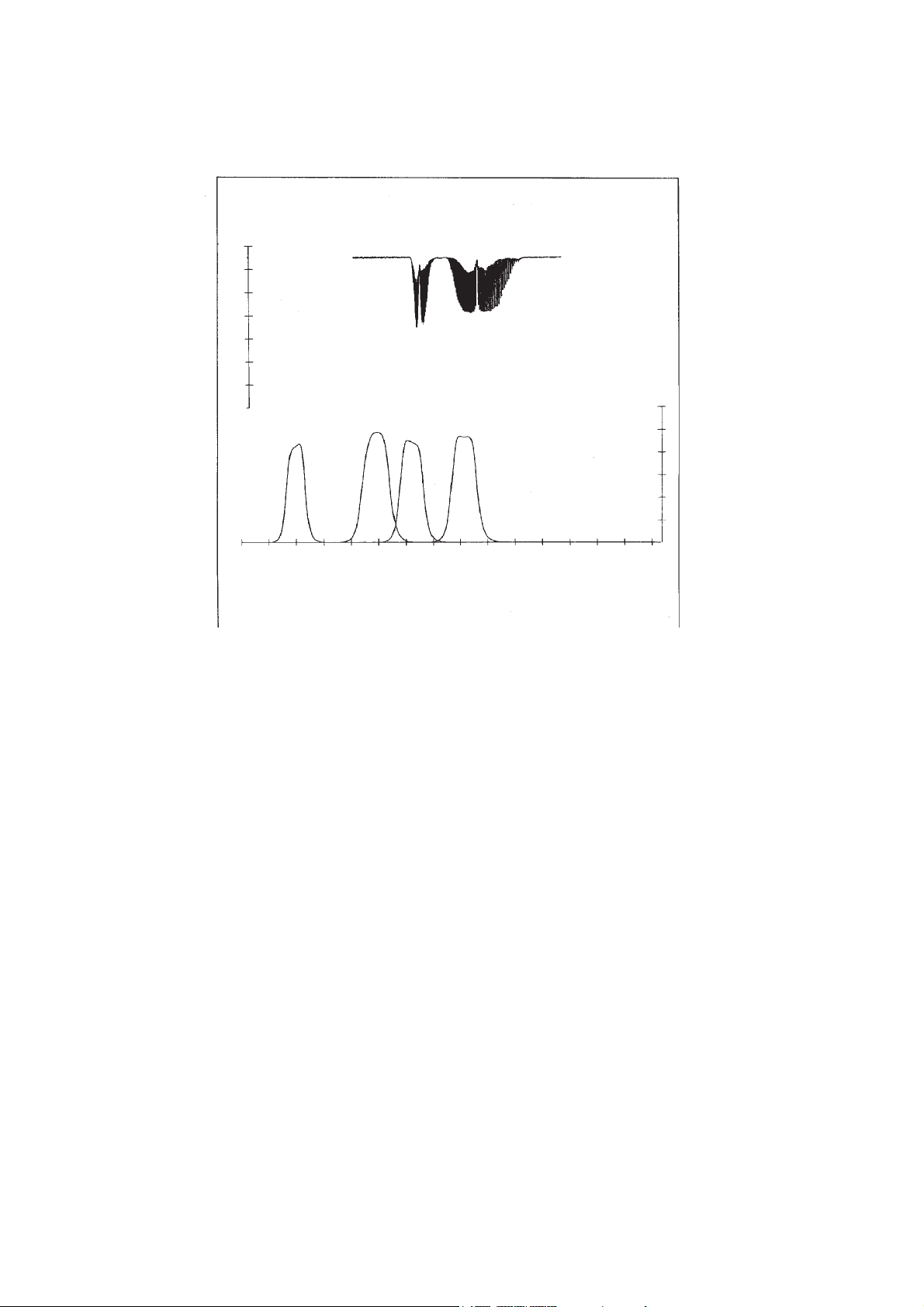
The spectral transmittance curves of the interference filters used in the 100 series analyzer and
the spectral absorption of the gases CO and CO2 are shown in Fig. 2-1. It can be seen that the
absorption bands of these gases each coincide with the passbands of one of the interference
filters. The fourth interference filter, used for generating a reference signal, has its passband in a
spectral region where none of these gases absorb. Most of the other gases of interest also do not
absorb within the passband of this reference filter.
ETC00781(1) Series 100 e 10/2001
2 - 1
Page 60
MEASURING PRINCIPLE
IR MEASUREMENT
9075604530150
Transmittance [%]
HC
Transmittance [%]
CO
2
CO
2
Reference
4400 460042004000 48003000 3200 3400 3600 3800 5000 5200 5400 5600 5800 6000
Wave Length [nm]
CO
CO
Interference -
Absorption Band
Filter
18 36 54 72 900
Fig. 2-1: Absorption Bands of Sample Gases and Transmittance of the
Interference Filters used
The signal generation happens by a pyroelectrical (solid-state) detector.
The detector records the incoming IR radiation. This radiation intensity is reduced by the
absorption of the gas at the corresponding wave lengths. By comparing the intensity at measuring
and reference wave length an alternating voltage signal is developed. This signal results from
cooling and heating of the pyroelectrical material of the detector.
2 - 2
ETC00781(1) Series 100 e 10/2001
Page 61

MEASURING PRINCIPLE
IR MEASUREMENT
2.1.2 Opto-Pneumatic Measuring Principle
A thermal radiator generates the infrared radiation passing through a chopper wheel. This
radiation alternately passes through a filter cell and reaches the measuring and reference side of
the analysis cell with equal intensity.
After passing another filter cell the radiation reaches the pneumatic detector.
The pneumatic detector compares and evaluates the radiation from the measuring and reference
sides and converts them into voltage signals proportional to their intensity via a preamplifier.
The detector consists of a gas-filled absorption and a compensation chamber which are
interconnected via a flow channel.
Absorption chamber
Flow channel with
Microflow sensor
CaF2 Window
Gas intake connection
Compensation chamber
ETC00781(1) Series 100 e 10/2001
Fig. 2-2: Principle Design of Gas Detector
2 - 3
Page 62

MEASURING PRINCIPLE
IR MEASUREMENT
In principle the detector is filled with the infrared active gas to be measured and is only sensitive
to this distinct gas with its characteristic absorption spectrum. The absorption chamber is sealed
with a window which are transparent for infrared radiation [usually CaF2 (Calcium fluoride)].
When the IR radiation passes through the reference side of the analysis cell into the detector, no
preabsorption occurs. Thus the gas inside the absorption chamber is heated, expands and some
of it passes through the flow channel into the compensation chamber.
When the IR radiation passes through the open measurement side of the analysis cell into the
detector, a part of it is absorbed depending on sample gas concentration. The gas in the absorption
chamber then is heated less than in the case of radiation coming from reference side. Absorption
chamber gas become colder, gas pressure in the absorption chamber is reduced and some gas
of compensation chamber passes through the flow channel into the absorption chamber.
The flow channel geometry is designed in such a way that it hardly impedes the gas flow by
restriction. Due to the radiation of chopper wheel, the different radiation intensities lead to
periodically repeated flow pulses within the detector.
The microflow sensor evaluates this flow and converts it into electrical voltages.
The electronics, which follow, evaluate the signals and convert them into the corresponding display
format.
2 - 4
ETC00781(1) Series 100 e 10/2001
Page 63

MEASURING PRINCIPLE
123
123
IR MEASUREMENT
2.1.3 Technique
The broadband emission from two IR sources (in the case of dual channel analyzers) passes
through the chopper blade, then, if IFC, through combinations of interference filters, if
optopneumatic principle depending on application through an optical filter (reduction of influences) and enters the analysis cells. The light transmitted through these cells is focused by filter
cells onto the according detector. The preamplified detector output signal is sent to microprocessor
circuitry, which converts the analytical signals to results expressed directly in physical concentration units (Vol.-%, ppm, mg/Nm3 etc.).
Light source
Analysis cell measuring side
Analysis cell reference side
MOTOR
Duplex filter disc
Adapter cell
(high measuring range)
Analysis cell
(undivided)
Filter cell
Preamplifier
Filter cell
Gas detector
ETC00781(1) Series 100 e 10/2001
Pyroelectrical detector
(solid-state detector)
Preamplifier
Chopper blade
Fig. 2-3: Principle Representation
2 - 5
Page 64

MEASURING PRINCIPLE
OXYGEN MEASUREMENT (PO2 PARAMAGNETIC PRINCIPLE)
2.2 Oxygen Measurement
Depending on analyzer model different measuring methods will be used.
The installed type of oxygen sensor is to identify at the channel code (see Fig. 1-1).
% O2 para. = paramagnetic Sensor
% O2 chem. = electrochemical Sensor
2.2.1 Paramagnetic Measurement
The determination of O2 concentration is based on the paramagnetic principle (magnetomechanic principle).
Two nitrogen filled (N2 is diamagnetic) quartz spheres are arranged in a "dumbbell" configuration
and suspended free to rotate on a thin platinum ribbon in a cell.
A small mirror that reflects a light beam coming from a light source to a photodetector, is mounted
on this ribbon. A strong permanent magnet especially shaped to produce a strong highly inhomogeneous magnetic field inside the analysis cell, is mounted outside the wall.
When oxygen molecules enter the cell, their paramagnetism will cause them to be drawn towards
the region of greatest magnetic field strength. The O2 molecules thus exert different forces which
produce a torque acting on the sphere arrangement, and the suspended “dumbbell”, along with
the mirror mounted on its suspension ribbon, will be angulary rotated away from the equilibrium
position.
The mirror then will deflect an incident light beam onto the photodetector which itself produces an
electric voltage. The electric signal is amplified and fed back to a conducting coil at the “dumbbell”,
forcing the suspended spheres back to the equilibrium position.
The current required to generate the restoring torque to return the “dumbbell” to its equilibrium
position is a direct measure of the O2 concentration in the gas mixture.
The complete analysis cell consists of analysis chamber, permanent magnet, processing
electronics, and a temperature sensor. The sensor itself is thermostat controlled up to approx. 55
°C. For warming up the measuring gas is conducted via a heat-exchanger.
Optionally we have built-in a solvent resistant cell or an intrinsic safe cell for potentially explosive
atmosphere.
2 - 6
ETC00781(1) Series 100 e 10/2001
Page 65

MEASURING PRINCIPLE
OXYGEN MEASUREMENT (PO2 PARAMAGNETIC PRINCIPLE)
ETC00781(1) Series 100 e 10/2001
Fig. 2-4: Principle Construction of paramagnetic Analysis Cell
1 Permanent magnet
2 Platinum wire
3 Mirror
4 Quartz spheres
5 Wire loop
6 Photodetector
7 Light source
8 Amplifier
9 Display
2 - 7
Page 66

MEASURING PRINCIPLE
OXYGEN MEASUREMENT (EO2 ELECTROCHEMICAL PRINCIPLE)
2.2.2 Electrochemical Measurement
The determination of O2 concentrations is based on the principle of a galvanic cell.
The principle structure of the oxygen sensor is shown in Fig. 2-5.
Lead wire (Anode)
Lead wire (Cathode)
Anode
O - ring (8)
Plastic disc (9)
Plastic top (10)
(1)
(Lead)
(Black)
Thermistor (5)
Acid electrolyte (3)
Sponge disc (7)
Cathode
(2)
Teflon membrane (4)
(Red)
Resistor (6)
(Gold film)
Fig. 2-5: Structure of electrochemical Oxygen Sensor
The oxygen senor incorporate a lead/gold oxygen cell with a lead anode (1) and a gold cathode
(2), using a specific acid electrolyte. To avoide moisture losses at the gold electrode a sponge sheet
is inserted on the purged side.
Oxygen molecules diffuse through a non-porous Teflon membrane (4) into the electrochemical cell
and are reduced at the gold-cathode. Water results from this reaction.
On the anode lead oxide is formed which is transferred into the electrolyte. The lead anode is
regenerated continuously and the electrode potential therefore remains unchanged for a long
time.
The rate of diffusion and so the response time (t90) of the sensor is dependent on the thickness
of the Teflon membrane.
2 - 8
ETC00781(1) Series 100 e 10/2001
Page 67

MEASURING PRINCIPLE
OXYGEN MEASUREMENT (EO2 ELECTROCHEMICAL PRINCIPLE)
(Red) (Black)
Thermistor (5)
(-)
Gold-
Cathode (2)
O2 + 4 H+ + 4 e- ¤ 2 H2O
Summary reaktion O
(11)
Electrolyte (3)
(ph 6)
+ 2 Pb ¤ 2 PbO
2
Resistor (6)
2 Pb + 2 H2O ¤ 2 PbO + 4 H+ + 4 e
Fig. 2-6: Reaction of galvanic cell
(+)
Lead-
Anode (1)
-
The electric current between the electrodes is proportional to the O2 concentration in the gas
mixture to be measured. The signals are measured as ter minal voltages of the resistor (6) and the
thermistor (5) for temperature compensation.
The change in output voltages (mV) of the senor (11) represents the oxygen concentration.
Note !
Depending on measuring principle the electrochemical O
of oxygen (residual humidity avoids drying of the cell). Supply cells continuously with dry sample gas
of low grade oxygen concentration or with oxygen-free sample gas could result a reversible detuning
sensitivity. The output signal will become instabil.
of O
2
For correct measurement the cells have to be supplied with O
We recommend to use the cells in intervall measurement (purge cells with conditioned (dust removal
but no drying) ambient air during measurement breaks).
If it is necessary to interrupt oxygen supply for several hours or days, the cell has to regenerate (supply
cell for about one day with ambient air). Temporary flushing with nitrogen (N2) for less than 1 h (e.g.
analyzer zeroing) will have no influence to measuring value.
cell needs a minimum internal consumption
2
concentrations of at least 0.1 Vol.-%.
2
ETC00781(1) Series 100 e 10/2001
2 - 9
Page 68

MEASURING PRINCIPLE
THERMAL CONDUCTIVITY (TC) MEASUREMENT
2.3 Thermal Conductivity Measurement
To measure gases like Hydrogen (H2), Argon (Ar) or Helium (He), the measurement method of
thermal conductivity (TC) will be used.
2.3.1 Sensor Design
The sensor consists of four small PT 100 resistors arranged in a Wheatstone Bridge which is
mounted into a block made of either aluminum, stainless steel or hastelloy, depending on the
application (e.g. stainless steel / hastelloy for corrosive gases). The block is thermostatted to
supress influence of external temperature change.
Fig. 2-7: Thermal conductivity sensor
2.3.2 Analysis Cell
Both the volume of the block and the mass of the resistors have been minimized on order
to obtain short response time.
The block contains two gas paths for sample and reference gas, whereat the reference gas
path is closed for standard applications. Always two sensors are located in the sample and
the reference gas path. The resistors are full glass packaged to withstand agressive gases.
The material in contact with the gases are glass, Gold, Aluminum, stainless steel and
Hastelloy, so a high resistance against corrosion by agressive gases is provided by this
cell.
2 - 10
ETC00781(1) Series 100 e 10/2001
Page 69

MEASURING PRINCIPLE
THERMAL CONDUCTIVITY (TC) MEASUREMENT
2.3.3 Measurement Method
The entire measurement cell is thermostatted to a temperature of up to 75 °C. The four sensors
are electrically heated to a higher temperature and the signal of the Wheatstone Bridge is
monitored. Depending on the thermal conductivity of the gases that pass the cell, the
temperature of the sensors in contact with the gas changes and thus their electrical resistance.
This changes the output signal of the Wheatstone Bridge and electronic circuitry processes this
signal to obtain standardized signal amplitudes, and transmits these to both an indicator
instrument and to the signal output connector.
ETC00781(1) Series 100 e 10/2001
2 - 11
Page 70

MEASURING PRINCIPLE
THERMAL CONDUCTIVITY (TC) MEASUREMENT
2 - 12
ETC00781(1) Series 100 e 10/2001
Page 71

PHOTOMETER ASSEMBLY
PYROELECTRICAL DETECTOR
3. Photometer Assembly
Depending on gas component and measuring range, different photometer assemblies will be
realized in 100 series.
Optional the photometer can be sealed to ambient air. In this case all par ts are sealed with O- rings.
The entire photometer assembly is mounted as a unit on the main circuit board (BKS) by means
of a bracket. The main circuit board is inserted into guide rails in the analyzer housing, to which
the front panel (membrane keypad) and the rear panel are assembled.
3.1 Photometer with Pyroelectrical Detector (Solid-state detector)
Fig. 3-1 shows the schematical photometer assembly for dual channel operation.
The base element for the photometer assembly is the chopper housing (03), upon which the light
source (thermal radiator, 07), the analysis cell (cuvette, 09), and the signal detection unit [filter cell
(14/15), pyroelectrical (solid-state) detector with integrated preamplifier (16)] are all mounted.
The chopper housing also incorporates the duplex filters (04/05) for the selection of spectral bandpass ranges from the broadband emission of the light sources.
Between the two halves of the chopper housing (03), which are sealed together with an O-ring,
is the chopper blade, driven by a stepping motor. Both the chopper housing and the motor
encapsulation are hermetically sealed with respect to the ambient in order to prevent entry of
gases, such as atmospheric CO2, which could produce background absorptivity (preabsorption)
leading to drift effects. An absorber material provides for constant removal of any traces of CO
which may enter the interior of the chopper housing via diffusion.
2
The chopper housing additionally incorporates a photoelectric gate for providing a reference
signal for the phase angle of the chopper blade, plus a temperature sensor (28) for monitoring
continuously the photometer assembly temperature. This temperature information is used by the
signal processing electronics for the compensation of thermal effects.
The analysis cells are merely aluminum tubes equipped with sample gas inlet and outlet fittings.
ETC00781(4) Series 100 e 02/2004
3 - 1
Page 72

PHOTOMETER ASSEMBLY
PYROELECTRICAL DETECTOR
This extremely simple and windowless design enables easy cleaning of the cells in the event of
contamination.
The only optical surfaces which also might become contaminated are the chopper windows and
the windows of the filter cells; these are accessible upon removal of the cell body.
The filter cell (14/15) has a necked conical shape for optimal adaptation of the analysis cell beam
cross - sectional profile to the active area of the detectors.
For high measurement ranges (up to 100 %), an adapter cell (10) is required.
The use of a spacer ring (08) creates an analysis cell in the space between the exit window of the
adapter cell and the entrance window of the filter cell.
3 - 2
ETC00781(4) Series 100 e 02/2004
Page 73

ETC00781(4) Series 100 e 02/2004
Fig. 3-1: Photometer Assembly with Pyroelectrical Detector
3 - 3
Legends:
03 Chopper Housing
04 / 05 Duplex Filter Disc
06 Zero - Adjustment Baffle (not for sealed photometer)
07 Light Source (thermal radiator)
08 Analysis Cell 1 - 7 mm (spacer ring)
09 Analysis Cell 50 - 200 mm
10 Adapter Cell
14/15 Filter Cell
16 Detector
17 Flange (light source)
18-21 O - Rings
22 Clamp (analysis cells 1-7 mm)
23 (24) Clamping Collar (analysis cells 1-7 mm)
25 Clamp (analysis cells 10-200 mm)
26 Light Source Mounting Screws
27 Mounting Screws for Analysis Cells/Adapter Cells
28 Temperature Sensor
PYROELECTRICAL DETECTOR
PHOTOMETER ASSEMBLY
Page 74

PHOTOMETER ASSEMBLY
GAS DETECTOR
3.2 Photometer with Gas Detector
Fig. 3-2 shows schematically the photometer assembly.
This assembly is similar to the assembly with pyroelectrical detector.
The analysis cells are separated into two halves by means of an internal wall along its axis and
both ends are sealed with windows. This divided the analysis cell in measuring side and reference
side.
Sample gas is flowing through measuring side while the closed reference side contains inert gas
(N2).
To prevent measuring errors by preabsorption, two absorber, fitted to the gas connections of the
reference side, absorb CO2 parts.
The filter cell has a single stage conical shape.
The gas detector is connected by a shielded cable to the separate preamplifier.
For small measuring ranges the preamplifier is mounted at the analysis cell.
For high measuring ranges the preamplifier is mounted at two holding clamps.
3 - 4
ETC00781(4) Series 100 e 02/2004
Page 75

PHOTOMETER ASSEMBLY
GAS DETECTOR
3521
44
ETC00781(4) Series 100 e 02/2004
16 5 4 623
Fig. 3-2: Photometer Assembly 100 Series with Gas Detector
[example above and middle: high measuring ranges,
example below: small measuring ranges.
1 Analysis Cell
2 Filter Cell
3 Gas Detector
4 Holding Device
5 Preamplifier
6 Absorber
3 - 5
Page 76

PHOTOMETER ASSEMBLY
3 - 6
ETC00781(4) Series 100 e 02/2004
Page 77

PREPARATION
5. Preparation of Start-up
Please check the package and its contents immediately upon receipt.
If any item is damaged or lost you are requested to notify the contractor to undertake a damage
survey and report the loss or damage to us immediately.
BINOS® 100 F:
Unscrew transfer safety lock of photometer sliding carriage (Fig. 5-1) !
Lock the system during transport !
Fig. 5-1: BINOS® 100 F, Photometer safety lock
ETC00781(4) Series 100 e 02/2004
5 - 1
Page 78

PREPARATION
INSTALLATION SITE
5.1 Installation Site
The analyzers must not operate in explosive atmosphere without supplementary
protective measures !
Free flow of air into and out of the analyzers (ventilation slits) must not be
hindered by nearby objects or walls !
Operate analyzer as table-top version or as rack-mountable version (built-in) only
(except of BINOS® 100 F: designed for wall mounting only) !
The installation site for the analyzers has to be dry and remain above freezing
point at all times. The analyzers must be exposed neither to direct sunlight nor
to strong sources of heat.
Be sure to observe the permissible ambient temperatures (c.f. chapter 27:
Technical Data). For outdoor installation, we recommend to install the analyzers
in a protective cabinet. At least, the analyzers has to be protected against rain
(e.g., shelter).
The BINOS 100 series analyzer has to be installed as near as possible to the sample point,
in order to avoid low response time caused by long sample gas lines.
In order to decrease the response time, a sample gas pump with a matching high pumping rate
may be used, while the analyzers has to be operated in the bypass mode or by an overflow
valve to prevent too high flow and too high pressure (Fig. 5-2).
Exhaust
5 - 2
Overpressure valve
Gas sampling pump
analyzer
Filter
Fig. 5-2: 100 series, Bypass installation
Flow meter
Exhaust
ETC00781(4) Series 100 e 02/2004
Page 79

PREPARATION
GAS CONDITIONING (SAMPLE HANDLING)
5.2 Gas Conditioning (Sample Handling)
The conditioning of the sample gas is of greatest importance for the successful operation of any
analyzer according to extractive method.
All gases have to be supplied to the analyzers as conditionned gases !
If corrosive gases are inserted into the instrument, it has is to be verified that there
are no gas components which may damage the gas path components.
The gas has to fullfil the following conditions:
It must
R be free of condensable constituents
R be free of dust
R be free of aggressive constituents which are not compatible with the material of the gas
paths.
R have temperatures and pressures which are within the specifications stated in “Technical
Data” of this manual.
Inflammable or explosive gas mixtures may not be introduced into the analyzers
without supplementary protective measures !
When analysing vapours, the dewpoint of the sample gas has to be at least 10 °C below the
ambient temperature in order to avoid the precipitation of condensate in the gas paths.
Suitable gas conditionning hardware may be supplied or recommended for specific analytical
problems and operating conditions.
ETC00781(4) Series 100 e 02/2004
5 - 3
Page 80

PREPARATION
GAS CONDITIONING (SAMPLE HANDLING)
5.2.1 Fine Dust Filter (Option BINOS® 100 2M/F)
A fine dust filter with a pore size of 2 µm may optionally be integrated into the
BINOS® 100 2M/F front panel (Fig. 1-2, Item 10, not for 2 channel analyzers with parallel gas
paths and for BINOS® 100 F analyzers used in hazardous area (Ex zones)).
5.2.2 Gas Sampling Pump (Option BINOS® 100 2M/F)
Optional BINOS® 100 2M/F can be equipped with a gas sampling pump (pumping rate max. 2.5
l/min., see chapter 7.4). For special solutions with 2 parallel measuring channels and 2 gas
sampling pumps consult factory.
Lifetime max. 5,000 hours of operation !
5.2.3 Pressure Sensor (Option)
It is possible to integrate a pressure sensor with a range of 800 - 1,100 hPa.
The concentration values computed by the analyzer will then be corrected to reflect the barometric
pressure to eliminate faulty measurements due to changes in barometric pressure (see technical
data, chapter 27.).
5.2.4 Gas Flow
The gas flow rate should be within the range 0.2 l/min to max. 1.5 l/min !
A constant flow rate of about 1 l/min is recommended.
The allowed gas flow rate for analyzers with paramagnetic oxygen sensor and
for BINOS® 100 F analyzers used in hazardous area (Ex zones) is max. 1.0 l/min!
BINOS® 100 2M/F with an optional fine dust filter (see chapter 5.2.1) allow to adjust the flow
with a screw driver via an optional integrated throttle.
It is possible to integrate up to two flow indicators into the BINOS® 100 2M/F front panel
(Fig. 1-2 to 1-4).
5 - 4
ETC00781(4) Series 100 e 02/2004
Page 81

PREPARATION
GAS CONNECTIONS
5.3 Gas Connections
The installed gas connections are depending on gas analyzer specification and model. All
fittings are clearly marked.
The fittings are located on the rear panel of the instrument or on the left bottom side.
The exhaust gas lines have to be mounted in a declining, pressureless
and frost-free way and according to the valid emission legislation !
Do not interchange gas inlets and gas outlets !
Ensure that all gas connections are made as labeled and are leak free !
Improper gas connections could result in explosion and death !
The unit´s exhaust may contain hydrocarbons and other toxic gases such as
carbon monoxide ! Carbon monoxide is highly toxic !
Permissible gas pressure max. 1,500 hPa !
5.3.1 Standard Configuration
Depending on analyzer version the following gas connections are installed:
in = Gas inlet out = Gas outlet
K 1 = measuring channel 1 K 2 = measuring channel 2
*)
Zero gas and span gas are introduced directly via the sample gas inlet. The test gas containers
have to be set up according to the current legislation.
Be sure to observe the safety regulations for the respective gases
(sample gas and test gases / span gases) and the gas bottles !
*)
for HYDROS® 100 with open reference side of sensor the gas fittings of channel 2 are used to
connect the reference gas.
ETC00781(4) Series 100 e 02/2004
5 - 5
Page 82

PREPARATION
GAS CONNECTIONS
K1 K2 K1 K2
Gas inlet
fittings
IN
X1 OUTPUT
INTERFACE
24 V
max. W
OUT
CROSS COMP.
3
12+ 1
Fig. 5-3a: BINOS® 100 (M), OXYNOS® 100 (EO2), HYDROS® 100, gas connections
X2 OUTPUT
INTERFACE
X1 OUTPUT
IN
Gas outlet
fittings
Gas inlet
fittings
5 - 6
24 V
max. 40 W
3
12+1
X3 OUTPUT
MADE I N GERMANY
Fig. 5-3b: OXYNOS® 100 (PO2), gas connections
OUT
Gas outlet
fittings
ETC00781(4) Series 100 e 02/2004
Page 83

PREPARATION
GAS CONNECTIONS
Gas inlet
fittings
Gas outlet
fittings
Fig. 5-3c: BINOS® 100 2M, standard gas connections
Wall mounting holder
ETC00781(4) Series 100 e 02/2004
Gas connections
Fig. 5-3d: BINOS® 100 F, standard gas connections
5 - 7
Page 84

PREPARATION
GAS CONNECTIONS
5.3.2 Internal Solenoid Valves (BINOS® 100 2M/F Option)
For operation with optional internal solenoid valves, the following indications have to be
considered:
All necessary gases have to be connected at the corresponding solenoid valve at an overpressure
of 50 - max. 500 hPa.
For 2 channel analyzer with parallel gas paths we can deliver a special solution with 2 valve blocks.
Be sure to observe the safety regulations for the respective gases
(sample gas and test gases / span gases) and the gas bottles !
The test gas containers have to be set up according to the valid regulations.
If a solenoid valve is open there is illuminated a green LED (Fig. 1-2, Item 3) at the front panel.
Solenoid valve:
common gas outlet
(to standard gas inlet K1)
Solenoid valve:
span gas 1
Solenoid valve:
span gas 2
5 - 8
Solenoid valve:
sample gas
Solenoid valve:
zero gas
Fig. 5-4a: BINOS® 100 2M (version A), gas connections with solenoid valve option
ETC00781(4) Series 100 e 02/2004
Page 85

0
K1 K2 K1 K2
PREPARATION
GAS CONNECTIONS
Solenoid valve:
span gas 1
IN OUT
X1 OUTPUT
IN/OUT
X2 OUTPUT X3 OUTPUT
DURCHFLUSS
MAX.1L/MI N
ANALOG I N
SPAN 1
SPAN 2
SAMPLE
ZERO
1
3
OUT
24V
max. 1 2
2
Fig. 5-4b: BINOS® 100 2M (version B), gas connections with solenoid valve option
Solenoid valve:
Span gas 1
channel 1
Solenoid valve:
not used
ANALOG IN
SPAN 1
!
SPAN 1
Solenoid valve:
span gas 2
Solenoid valve:
common gas outlet
(to standard gas inlet K1)
Solenoid valve:
sample gas
Solenoid valve:
zero gas
Solenoid valve:
not used
Solenoid valve:
Span gas 2
channel 2
Solenoid valve:
common gas outlet
channel 1
(to standard gas inlet K1)
Solenoid valve:
sample gas
channel 1
Solenoid valve:
zero gas
channel 1
SPAN 2
SAMPLE
ZERO
OUT
24V
120W
1
OUT
2
3
SPAN 2
SAMPLE
ZERO
Solenoid valve:
Common gas outlet
channel 2
(to standard gas inlet K2)
Solenoid valve:
sample gas
channel 2
Solenoid valve:
zero gas
channel 2
Fig. 5-4c: BINOS® 100 2M (special version), gas connections with 2 solenoid valve blocks
ETC00781(4) Series 100 e 02/2004
5 - 9
Page 86

PREPARATION
PURGE GAS CONNECTIONS OF BINOS® 100 F / CONTINUOUS PURGE
5.3.3 Purge gas connection of BINOS® 100 F for Ex zones
a) ATEX Applications
Refer to the supplemental manual for installing analyzers in hazardous
areas where ATEX is applicable.
b) Z purge for CSA-C/US Ex Zone 2 Non-Flammable Atmospheres
This analyzer is not designed for analysis of flammable sample !
Introduction of flammable samples into this equipment could result in explosion,
causing severe personal injury, death or property damage !
Consult factory if flammable samples are to be measured !
Z Purge kit is designed for protection against the invasion of flammable gases into enclosure from
outside atmosphere only. It does not provide protection against the release of inflammable gases
contained in the sample gas via internal leakages.
P Connect purge gas (air or N2) to the BINOS® 100 F inlet via 1/4" O.D. tube connection
(see Fig. 27-4) !
Outlet is done via 3/8" O.D. fitting with analyzer specific insert throttle.
P Use purge gas supply under pressure of 58 psig (4 bar; 5,000 hPa abs.).
. This will provide a flow rate approx. 55 scfh (26 l/min.). At this flow rate, five case volumes
of purge gas will pass through the instrument in 11 minutes.
After 11 minutes, reduce the pressure to 5.1 psig (350 mbar; 1,350 hPa abs.), resulting in
a flow rate of approx. 18 scfh (8.5 l/min.). This will provide an enclosure over-pressure of
approx. 0.24 inch H2O (0.6 hPa) for continuous purge.
Pressure inside the housing must not exceed 5 hPa at normal operation or
10 hPa for a short time of less than 1/2 hour resp. !
5 - 10
ETC00781(4) Series 100 e 02/2004
Page 87

PREPARATION
PURGE GAS CONNECTIONS OF BINOS® 100 F / Z PURGE
5.4 Additional Hints to BINOS® 100 F (Field Housing)
In the field housing version BINOS® 100 F all componets are incorporated into a protection
housing going conform to DIN-standard protection class IP 65 (approx. NEMA 4/4X). This
housing is designed for wall mounting.
For installation in hazardous areas the BINOS® 100 F is equipped with an impact tested front
panel (according to CENELEC, EN 50014) with touch screen keypad. Optionally we can
provide additional intrinsically safe I/O's and/or ex interface relays (couplers). For European ex
zone 2 a simplified pressurization is installed and individual approval is provided. An EExp
approved “purge system” for European ex zone 1 (both according to CENELEC, EN 50016) or
with Z Purge for measurement of non-flammable gases in hazardous areas (according to CSAC/US for North American Ex zone 2) is another option.
Be sure to observe the additional notes, safety precautions and warnings given
in the individual manuals (simplified pressurization for ex zone 2 /
EExp approved “purge system” for ex zone 1) and in section “Safety Summary,
subsection VII.!
ETC00781(4) Series 100 e 02/2004
5 - 11
Page 88

PREPARATION
0
ADDITIONAL HINTS ON BINOS® 100 F (FIELD HOUSING)
5.4.1 Wall Mounting
This housing is designed for wall mounting.
Location of fixing points: see Fig. 5-5.
Lift or carry housing with at least 2 persons because of the high weight of field
housing BINOS® 100 F (approx. 30 - 35 kg for standard housing).
For easy transport use a suitable cart.
Lift points are labeled ! Labels showing down side for transport !
Do not use electronics of optional “purge system” as handle !
Take care to use anchors and bolts specified to be used for the weight
of the units!
Take care the wall the unit is intended to be installed at is solid and
stable to hold the units!
550
492
approx. 355
300
332
1
18
Glands
(connection cables)
Fig. 5-5: Dimensional sketch / Drill drawing BINOS® 100 F Standard version
[all dimensions in mm]
5 - 12
ETC00781(4) Series 100 e 02/2004
18
Page 89

®
ADDITIONAL HINTS ON BINOS
100 F (FIELD HOUSING)
5.4.2 Electrical Connections
Be sure to observe the safety precautions and warnings !
Verify, that the cable glands together with installed cables are hermetic
to ensure protection class IP 65 (according to IEC 60529).
The permissible outside diameters of the cables are 7 to 12 mm !
a) Mains Supply
PREPARATION
The analyzer is rated for an operating voltage of 230 V AC or 120 V AC, 47-63 Hz.
The built-in power supply is either of type SL5 or of type SL10 and provides a switch to
manually select the nominal voltage.
P Open the analyzers front door.
P Insert the mains line through the cable glands (Fig. 5-6 or 5-5) into the housing.
Connect L , N and PE to the terminals located nearby the powerline filter (Fig. 5-8).
Verify that the line voltage given on the identification plate
(front door inside) complies with that of your power supply line !
Verify that the position of the power supply's voltage selector switch complies
with the voltage of your power supply line (Fig. 27-7, 27-8 and 5-8) !
The BINOS® 100 F (field housing) has no switch with disconnect function.
The customer has to provide a switch or circuit breaker into his installation. This
switch has to be installed near by analyzer, must be easily attainable for operator
and has to be charaterized as disconnector for analyzer.
cable glands
for data lines
cable gland
for mains line
Wall mounting
holder
ETC00781(4) Series 100 e 02/2004
Front door
Gas connections
Fig. 5-6: BINOS® 100 F, cable glands for lines (side view from left)
5 - 13
Page 90

PREPARATION
ADDITIONAL HINTS ON BINOS® 100 F (FIELD HOUSING)
b) Optional Signal Lines
This are analog outputs, digital inputs/outputs and serial interfaces.
P Open the analyzer's front door.
P Insert the cable through the cable glands (Fig. 5-6 and 5-5) into the housing.
Connection is to be done to the respective terminal strips (Fig. 5-7 and 5-8).
Assignment see chapter 2.
Cables to external dataprocessing have to be double-insulated against mains
voltage for analyzer BINOS® 100 F !
Use only shielded cables for signal lines! To ensure proper electromagnetic
compatibility (EMC) it is recommended to follow the installation steps given
below.
All unused cable glands need to be sealed using a sealing plug
(part no. ETC00791 or similiar)
Unused cable gland openings in the enclosure need to be covered using a
special screw (part no. ETC 000790 or similiar).
Cable Gland Assembly Instruction
for Shielded Cables
1. Strip the cable
insulation
2. Uncover the
shielding
5 - 14
3. Feed cable through
gland nut and into
fixing element
4. Put the shielding
net over the element
the way that it
covers the o-ring 2
mm.
5. Stick the fixing
element into the
neck and fix the
gland.
ETC00791
Cable gland sealing plug
ETC00790
Cable gland allen
screw sealing plug
ETC00781(4) Series 100 e 02/2004
Page 91

PREPARATION
Terminal strips for
data lines
X9
1
X11
1
2
1
F100.1
F100.2
X10
4321
Interface
Serial out
Terminal strip Interface:
serial interface option
Power supply
ETC00781(4) Series 100 e 02/2004
Fig. 5-7: BINOS® 100 F, Data line connections
Inside view from front (detail, without front door)
5 - 15
Page 92

PREPARATION
ADDITIONAL HINTS TO BINOS
®
100 F (FIELD HOUSING)
Terminal strip X2:
analog outputs
Terminal strip X3:
digital outputs
X2 Analog out
X3 Digital out
X1 Status
Tterminal strips
for mains cord
PE
N L
N L
PE
Powerline filter
(connection of L and N of mains line)
5 - 16
Terminal strip X1:
output (status) relays option
Ground conductor pin
(PE mains line)
Fig. 5-8: BINOS® 100 F, Connection data lines / mains line
(inside view, left side panel)
ETC00781(4) Series 100 e 02/2004
Page 93

SWITCHING ON
GENERAL
6. Switching On
6.1 General
Be sure to observe the safety precautions and warnings !
Once the instrument has been correctly assembled and installed in accordance with the general
instructions given in section 5., the equipment is ready for operation.
The equipment is switched on by providing the required voltage.
The presence of the supply voltage will be indicated by the illumination of the LED displays.
Upon connection of the supply voltage, the analyzer will perform a self diagnostic test routine.
First the actual program version will be shown.
(analyzers without fieldbus) or (analyzers with fieldbus)
Finally either concentration values or error messages will be displayed
If as a result of a battery fault the default values were charged, this will be shown by a flushing “batt.”
This message will disappear after depressing any key.
Analyzer warming-up takes about 15 to 50 minutes, depending on the
installed detectors !
Before starting an analysis, however, the following should be performed:
R entry of the desired system parameters,
R calibration of the analyzer.
Note:
The "X’s" shown in the display indicate a number or combinations of numbers.
ETC00781(4) Series 100 e 02/2004
6 - 1
Page 94

SWITCHING ON
24 V DC SUPPLY
6.2 24 V DC Supply
The analyzers of series 100 (with except of BINOS® 100 F and BINOS® 100 2M with internal power
supply) are specified for an operating voltage of 24 V DC. This voltage has to be provided via
a 3-pole XLR flange (male).
The DC supply voltage has to be provided by one of the optional power supplies VSE 2000,
UPS 01 T, DP 157, SL5, SL10 or an equivalent power supply.
P Connect power supply and analyzer (Fig. 6-1, Plug 24 V DC).
Verify correct polarity before operation (Fig. 29-1) !
P Connect mains line and power supply.
Be sure to observe the safety precautions and warnings given by
manufacturer of power supply !
6.3 230/120 V AC Supply
X1 OUTPUT
INTERFACE
X2 OUTPUT
24 V
max. W
3
12+ 1
X3 OUTPUT
Plug 24 V DC
Input
6 - 2
MADE I N GERMANY
Fig. 6-1a: BINOS® 100 (M), OXYNOS® 100 (EO2), HYDROS® 100, Voltage supply
ETC00781(4) Series 100 e 02/2004
Page 95

SWITCHING ON
24 V DC SUPPLY
Plug 24 V DC
Input
X2 OUTPUT
INTERFACE
X1 OUTPUT
24 V
max. 40 W
2+
3
Fig. 6-1b: OXYNOS® 100 (PO2), Voltage supply
IN
OUT
K1 K2 K1 K2
DIGITAL IN
IN OUT
X1 OUTPUT
IN/OUT
X2 OUTPUT X3 OUTPUT
DURCHFLUSS
MAX. 1 L/ MIN
ANALOG I N
SPAN 1
SPAN 2
SAMPLE
ZERO
1
3
OUT
2
24V
max.120W
V+
V-
E1
E2
E3
E4
E5
E6
E7
FB+
FBFB+
FB-
Plug 24 V DC
Fig. 6-1c: BINOS® 100 2M (version B) with external power supply, Voltage supply
Input
ETC00781(4) Series 100 e 02/2004
6 - 3
Page 96

SWITCHING ON
230/120 V AC SUPPLY
6.3.1 BINOS® 100 2M
The analyzer BINOS® 100 2M is optional lly equipped with an internal “autoranging” power
supply and is specified for an operating voltage of 230 V AC or 120 V AC resp., 47-63 Hz.
For supply of external components / analyzers there is built in a 24 VDC outlet (a 3-pole XLR flange,
female, max. 2 A).
P Connect internal power supply and external components (Fig. 6-2, 24 V DC out).
24 VDC supply to external components/analyzers with the internal power
supply of BINOS® 100 2M requires a fuse to be connected in series to the
consumer which limits the current consumption to max. 2 A !
Verify correct polarity for 24 V DC supply to external components before
operation (Section 29.) !
P Connect mains line and internal power supply (Fig. 6-2, V AC in).
Verify beforehand that the line voltage stated on the power supply meets that
of your power supply line !
The socket outlet shall be installed near the equipment.
6 - 4
ETC00781(4) Series 100 e 02/2004
Page 97

SWITCHING ON
230/120 V AC SUPPLY
Socket 24 V DC out
Input
230/120 V AC
POWER
Fig. 6-2: BINOS® 100 2M (version A) shown with internal power supply, Voltage supply
6.3.2 BINOS® 100 F
The analyzer is specified for an operating voltage of 230 V AC or 120 V AC resp., 47-63 Hz..
Built-in power supply (manual switch between 230/120 VAC) is either power supply of type SL5
or of type SL10.
Once the instrument has been correctly assembled and installed in accordance with the general
instructions given in section 5., 5.3.3 and 5.4, the equipment is ready for operation.
The analyzer is switched on by providing the required voltage.
ETC00781(4) Series 100 e 02/2004
6 - 5
Page 98

SWITCHING ON
6 - 6
ETC00781(4) Series 100 e 02/2004
Page 99

KEY FUNCTIONS
7. Key Functions
By default the analyzer is operated and programmed by using the membrane keypad with its
four keys (see Fig. 1-1 and 1-2, Item 4 to 7).
If either the BINOS100® 2M or BINOS 100 F analyzer is equipped with an internal pump, the
fifth key “PUMP” is activated by software. (see Fig. 1-2. Item 8 and chapter 7.4).
BINOS® 100 F for use in rough surroundings may optionally be equipped with a touch screen
keypad without fifth key for gas sampling pump. In this case the pump is controlled via software
menu.
Operator guidance prompts will appear on the 4 digit LED displays.
Battery buffering of the stored parameters prevents their loss in the absense of voltage supply.
ETC00781(4) Series 100 e 02/2004
7 - 1
Page 100

KEY FUNCTIONS
FUNCTION
7.1 FUNCTION
Pressing this key (Fig. 1-1 and 1-2, Item 3) addresses the individual analyzer functions in
sequence. Merely addressing an analyzer function will not initiate an analyzer action or operation.
The analyzer will stay in measurement mode until the ENTER key is pressed.
Remark concerning the optional touch screen keypad:
To avoid unintended keypad activation all the keys are secured by an additional
user code. This code has to be entered each time before leaving the
measurement display:
After pressing the FUNCTION key the text "Code" appears in the upper display and
the following keys have to be pressed within a time period of 20 seconds: DOWN,
UP, ENTER, FUNCTION. Pressing the correct sequence shows the text "Code" in
the lower display too and menu scrolling is enabled.
If the correct code is not entered within the time period of 20 seconds menu scrolling
will still be locked and the measurement display is shown again.
7 - 2
ETC00781(4) Series 100 e 02/2004
 Loading...