

Page 1
Reference Manual
00809-0100-4663, Rev BA
January 2010
Rosemount 8732
Integral Mount or Remote Mount Magnetic
Flowmeter System with F
OUNDATION
™
fieldbus
www.rosemount.com
Page 2

Page 3

Reference Manual
NOTICE
00809-0100-4663, Rev BA
January 2010
Rosemount 8732
Integral Mount or Remote Mount
Magnetic Flowmeter System with
OUNDATION
F
Read this manual before working with the product. For personal and system safety, and for
optimum product performance, make sure you thoroughly understand the contents before
installing, using, or maintaining this product.
Rosemount Inc. has two toll-free assistance numbers:
Customer Central
Technical support, quoting, and order-related questions.
United States - 1-800-999-9307 (7:00 am to 7:00 pm CST)
Asia Pacific- 65 777 8211
Europe/ Middle East/ Africa - 49 (8153) 9390
North American Response Center
Equipment service needs.
1-800-654-7768 (24 hours—includes Canada)
Outside of these areas, contact your local Rosemount representative.
™
fieldbus
The products described in this document are NOT designed for nuclear-qualified
applications. Using non-nuclear qualified products in applications that require
nuclear-qualified hardware or products may cause inaccurate readings.
For information on Rosemount nuclear-qualified products, contact your local Rosemount
Sales Representative.
www.rosemount.com
Page 4

Page 5

Reference Manual
00809-0100-4663, Rev BA
January 2010
Rosemount 8732
Table of Contents
SECTION 1 Introduction
SECTION 2 Installation
System Description. . . . . . . . . . . . . . . . . . . . . . . . . . . . . . . . . . . . . . . . . . . . . . .1-1
Safety Messages . . . . . . . . . . . . . . . . . . . . . . . . . . . . . . . . . . . . . . . . . . . . . . . .1-2
Service Support . . . . . . . . . . . . . . . . . . . . . . . . . . . . . . . . . . . . . . . . . . . . . . . . .1-2
Safety Messages . . . . . . . . . . . . . . . . . . . . . . . . . . . . . . . . . . . . . . . . . . . . . . . .2-1
Transmitter Symbols. . . . . . . . . . . . . . . . . . . . . . . . . . . . . . . . . . . . . . . . . . . . . .2-2
Pre-Installation . . . . . . . . . . . . . . . . . . . . . . . . . . . . . . . . . . . . . . . . . . . . . . . . . .2-2
Mechanical Considerations. . . . . . . . . . . . . . . . . . . . . . . . . . . . . . . . . . . . . . . . .2-2
Environmental Considerations . . . . . . . . . . . . . . . . . . . . . . . . . . . . . . . . . . . . . .2-3
Installation Procedures. . . . . . . . . . . . . . . . . . . . . . . . . . . . . . . . . . . . . . . . . . . .2-3
Mount the Transmitter . . . . . . . . . . . . . . . . . . . . . . . . . . . . . . . . . . . . . . . . . .2-3
Identify Options and Configurations . . . . . . . . . . . . . . . . . . . . . . . . . . . . . . .2-4
Hardware Switches . . . . . . . . . . . . . . . . . . . . . . . . . . . . . . . . . . . . . . . . . . . .2-4
Conduit Ports and Connections. . . . . . . . . . . . . . . . . . . . . . . . . . . . . . . . . . .2-5
Conduit Cables . . . . . . . . . . . . . . . . . . . . . . . . . . . . . . . . . . . . . . . . . . . . . . .2-6
Electrical Considerations. . . . . . . . . . . . . . . . . . . . . . . . . . . . . . . . . . . . . . . .2-6
Installation Category . . . . . . . . . . . . . . . . . . . . . . . . . . . . . . . . . . . . . . . . . . .2-7
Overcurrent Protection . . . . . . . . . . . . . . . . . . . . . . . . . . . . . . . . . . . . . . . . .2-7
Connect Transmitter Power. . . . . . . . . . . . . . . . . . . . . . . . . . . . . . . . . . . . . .2-7
Connect F
Transmitter Communication Input . . . . . . . . . . . . . . . . . . . . . . . . . . . . . . . . .2-8
Power Conditioning . . . . . . . . . . . . . . . . . . . . . . . . . . . . . . . . . . . . . . . . . . . .2-8
Field Wiring . . . . . . . . . . . . . . . . . . . . . . . . . . . . . . . . . . . . . . . . . . . . . . . . . .2-8
Transmitter Wiring Connection . . . . . . . . . . . . . . . . . . . . . . . . . . . . . . . . . . .2-9
Sensor Connections . . . . . . . . . . . . . . . . . . . . . . . . . . . . . . . . . . . . . . . . . . . . .2-11
Rosemount Sensors . . . . . . . . . . . . . . . . . . . . . . . . . . . . . . . . . . . . . . . . . .2-11
Transmitter to Sensor Wiring. . . . . . . . . . . . . . . . . . . . . . . . . . . . . . . . . . . .2-11
Conduit Cables . . . . . . . . . . . . . . . . . . . . . . . . . . . . . . . . . . . . . . . . . . . . . .2-12
Sensor to Remote Mount Transmitter Connections . . . . . . . . . . . . . . . . . .2-13
OUNDATION fieldbus Wiring . . . . . . . . . . . . . . . . . . . . . . . . . . . . . .2-8
SECTION 3 Configuration
Introduction. . . . . . . . . . . . . . . . . . . . . . . . . . . . . . . . . . . . . . . . . . . . . . . . . . . . .3-1
Local Operator Interface. . . . . . . . . . . . . . . . . . . . . . . . . . . . . . . . . . . . . . . . . . .3-1
Basic Features . . . . . . . . . . . . . . . . . . . . . . . . . . . . . . . . . . . . . . . . . . . . . . . . . .3-1
Data Entry . . . . . . . . . . . . . . . . . . . . . . . . . . . . . . . . . . . . . . . . . . . . . . . . . . .3-2
LOI Examples. . . . . . . . . . . . . . . . . . . . . . . . . . . . . . . . . . . . . . . . . . . . . . . . . . .3-2
Table Value Example . . . . . . . . . . . . . . . . . . . . . . . . . . . . . . . . . . . . . . . . . .3-3
Select Value Example . . . . . . . . . . . . . . . . . . . . . . . . . . . . . . . . . . . . . . . . . .3-3
Display Lock . . . . . . . . . . . . . . . . . . . . . . . . . . . . . . . . . . . . . . . . . . . . . . . . .3-3
Start Totalizer . . . . . . . . . . . . . . . . . . . . . . . . . . . . . . . . . . . . . . . . . . . . . . . .3-3
Stop Totalizer . . . . . . . . . . . . . . . . . . . . . . . . . . . . . . . . . . . . . . . . . . . . . . . .3-3
Reset Totalizer . . . . . . . . . . . . . . . . . . . . . . . . . . . . . . . . . . . . . . . . . . . . . . .3-3
Diagnostic Messages . . . . . . . . . . . . . . . . . . . . . . . . . . . . . . . . . . . . . . . . . . . . .3-5
Review. . . . . . . . . . . . . . . . . . . . . . . . . . . . . . . . . . . . . . . . . . . . . . . . . . . . . .3-5
Process Variables. . . . . . . . . . . . . . . . . . . . . . . . . . . . . . . . . . . . . . . . . . . . . . . .3-5
PV - Primary Variable . . . . . . . . . . . . . . . . . . . . . . . . . . . . . . . . . . . . . . . . . .3-6
PV -% Range. . . . . . . . . . . . . . . . . . . . . . . . . . . . . . . . . . . . . . . . . . . . . . . . .3-6
PV - Analog Output . . . . . . . . . . . . . . . . . . . . . . . . . . . . . . . . . . . . . . . . . . . .3-6
Totalizer Setup . . . . . . . . . . . . . . . . . . . . . . . . . . . . . . . . . . . . . . . . . . . . . . .3-6
Pulse Output . . . . . . . . . . . . . . . . . . . . . . . . . . . . . . . . . . . . . . . . . . . . . . . . .3-7
TOC-1
Page 6

Rosemount 8732
Reference Manual
00809-0100-4663, Rev BA
January 2010
Basic Setup . . . . . . . . . . . . . . . . . . . . . . . . . . . . . . . . . . . . . . . . . . . . . 3-7
Tag . . . . . . . . . . . . . . . . . . . . . . . . . . . . . . . . . . . . . . . . . . . . . . . . . 3-7
Flow Units. . . . . . . . . . . . . . . . . . . . . . . . . . . . . . . . . . . . . . . . . . . . 3-7
Line Size. . . . . . . . . . . . . . . . . . . . . . . . . . . . . . . . . . . . . . . . . . . . . 3-9
PV URV (Upper Range Value). . . . . . . . . . . . . . . . . . . . . . . . . . . 3-10
PV LRV (Lower Range Value) . . . . . . . . . . . . . . . . . . . . . . . . . . . 3-10
Calibration Number. . . . . . . . . . . . . . . . . . . . . . . . . . . . . . . . . . . . 3-11
PV Damping . . . . . . . . . . . . . . . . . . . . . . . . . . . . . . . . . . . . . . . . . 3-11
SECTION 4 Operation
SECTION 5 Sensor Installation
Introduction . . . . . . . . . . . . . . . . . . . . . . . . . . . . . . . . . . . . . . . . . . . . . 4-1
Diagnostics . . . . . . . . . . . . . . . . . . . . . . . . . . . . . . . . . . . . . . . . . . . . . 4-1
Diagnostic Controls . . . . . . . . . . . . . . . . . . . . . . . . . . . . . . . . . . . . 4-1
Basic Diagnostics. . . . . . . . . . . . . . . . . . . . . . . . . . . . . . . . . . . . . . 4-2
Advanced Diagnostics . . . . . . . . . . . . . . . . . . . . . . . . . . . . . . . . . . 4-3
Diagnostic Variables. . . . . . . . . . . . . . . . . . . . . . . . . . . . . . . . . . . . 4-8
Trims. . . . . . . . . . . . . . . . . . . . . . . . . . . . . . . . . . . . . . . . . . . . . . . . 4-9
Status . . . . . . . . . . . . . . . . . . . . . . . . . . . . . . . . . . . . . . . . . . . . . . 4-11
Advanced Configuration . . . . . . . . . . . . . . . . . . . . . . . . . . . . . . . . . . 4-12
Detailed Setup. . . . . . . . . . . . . . . . . . . . . . . . . . . . . . . . . . . . . . . . . . 4-12
Additional Parameters . . . . . . . . . . . . . . . . . . . . . . . . . . . . . . . . . 4-12
Display Language. . . . . . . . . . . . . . . . . . . . . . . . . . . . . . . . . . . . . 4-13
Signal Processing. . . . . . . . . . . . . . . . . . . . . . . . . . . . . . . . . . . . . 4-13
Device Info . . . . . . . . . . . . . . . . . . . . . . . . . . . . . . . . . . . . . . . . . . 4-15
Mode . . . . . . . . . . . . . . . . . . . . . . . . . . . . . . . . . . . . . . . . . . . . . . . . . 4-17
Block Mode: Target . . . . . . . . . . . . . . . . . . . . . . . . . . . . . . . . . . . 4-18
Block Mode: Actual. . . . . . . . . . . . . . . . . . . . . . . . . . . . . . . . . . . . 4-18
Block Mode: Permitted . . . . . . . . . . . . . . . . . . . . . . . . . . . . . . . . 4-18
Block Mode: Normal . . . . . . . . . . . . . . . . . . . . . . . . . . . . . . . . . . . 4-18
Safety Messages. . . . . . . . . . . . . . . . . . . . . . . . . . . . . . . . . . . . . . . . . 5-1
Sensor Handling . . . . . . . . . . . . . . . . . . . . . . . . . . . . . . . . . . . . . . . . . 5-3
Sensor Mounting . . . . . . . . . . . . . . . . . . . . . . . . . . . . . . . . . . . . . . . . . 5-4
Upstream/Downstream
Piping . . . . . . . . . . . . . . . . . . . . . . . . . . . . . . . . . . . . . . . . . . . . . . . 5-4
Sensor Orientation . . . . . . . . . . . . . . . . . . . . . . . . . . . . . . . . . . . . . 5-4
Flow Direction. . . . . . . . . . . . . . . . . . . . . . . . . . . . . . . . . . . . . . . . . 5-6
Installation (Flanged Sensor). . . . . . . . . . . . . . . . . . . . . . . . . . . . . . . . 5-7
Gaskets . . . . . . . . . . . . . . . . . . . . . . . . . . . . . . . . . . . . . . . . . . . . . 5-7
Flange Bolts . . . . . . . . . . . . . . . . . . . . . . . . . . . . . . . . . . . . . . . . . . 5-7
Installation
(Wafer Sensor) . . . . . . . . . . . . . . . . . . . . . . . . . . . . . . . . . . . . . . . . . 5-10
Gaskets . . . . . . . . . . . . . . . . . . . . . . . . . . . . . . . . . . . . . . . . . . . . 5-10
Flange Bolts . . . . . . . . . . . . . . . . . . . . . . . . . . . . . . . . . . . . . . . . . 5-11
Installation
(Sanitary Sensor). . . . . . . . . . . . . . . . . . . . . . . . . . . . . . . . . . . . . . . . 5-12
Gaskets . . . . . . . . . . . . . . . . . . . . . . . . . . . . . . . . . . . . . . . . . . . . 5-12
Alignment and Bolting. . . . . . . . . . . . . . . . . . . . . . . . . . . . . . . . . . 5-12
Grounding . . . . . . . . . . . . . . . . . . . . . . . . . . . . . . . . . . . . . . . . . . . . . 5-12
Process Leak Protection (Optional). . . . . . . . . . . . . . . . . . . . . . . . . . 5-16
Standard Housing Configuration . . . . . . . . . . . . . . . . . . . . . . . . . 5-16
Relief Valves. . . . . . . . . . . . . . . . . . . . . . . . . . . . . . . . . . . . . . . . . 5-17
Process Leak Containment . . . . . . . . . . . . . . . . . . . . . . . . . . . . . 5-17
TOC-2
Page 7

Reference Manual
00809-0100-4663, Rev BA
January 2010
Rosemount 8732
SECTION 6 Maintenance and Troubleshooting
APPENDIX A Reference Data
APPENDIX B Approval Information
Safety Information . . . . . . . . . . . . . . . . . . . . . . . . . . . . . . . . . . . . . . . . 6-1
Installation Check and Guide. . . . . . . . . . . . . . . . . . . . . . . . . . . . . . . . 6-2
Diagnostic Messages. . . . . . . . . . . . . . . . . . . . . . . . . . . . . . . . . . . . . . 6-3
Transmitter Troubleshooting . . . . . . . . . . . . . . . . . . . . . . . . . . . . . . . . 6-5
Quick Troubleshooting. . . . . . . . . . . . . . . . . . . . . . . . . . . . . . . . . . . . . 6-7
Step 1: Wiring Errors . . . . . . . . . . . . . . . . . . . . . . . . . . . . . . . . . . . 6-7
Step 2: Process Noise . . . . . . . . . . . . . . . . . . . . . . . . . . . . . . . . . . 6-7
Step 3: Installed Sensor Tests . . . . . . . . . . . . . . . . . . . . . . . . . . . . 6-7
Step 4: Uninstalled Sensor Tests. . . . . . . . . . . . . . . . . . . . . . . . . . 6-9
Functional Specifications. . . . . . . . . . . . . . . . . . . . . . . . . . . . . . . . . . .A-1
Foundation
Performance Specifications. . . . . . . . . . . . . . . . . . . . . . . . . . . . . . . . .A-5
Physical Specifications . . . . . . . . . . . . . . . . . . . . . . . . . . . . . . . . . . . .A-7
Product Certifications. . . . . . . . . . . . . . . . . . . . . . . . . . . . . . . . . . . . . .B-1
Approved Manufacturing Locations. . . . . . . . . . . . . . . . . . . . . . . . . . .B-1
European Directive Information. . . . . . . . . . . . . . . . . . . . . . . . . . . . . .B-1
ATEX Directive. . . . . . . . . . . . . . . . . . . . . . . . . . . . . . . . . . . . . . . .B-1
European Pressure Equipment Directive (PED) (97/23/EC) . . . . .B-1
Electro Magnetic Compatibility (EMC) (2004/108/EC) . . . . . . . . . .B-2
Low Voltage Directive (93/68/EEC) . . . . . . . . . . . . . . . . . . . . . . . .B-2
Low Voltage Directive (2006/95/EC) . . . . . . . . . . . . . . . . . . . . . . .B-2
Other important guidelines . . . . . . . . . . . . . . . . . . . . . . . . . . . . . . .B-2
IECEx Scheme. . . . . . . . . . . . . . . . . . . . . . . . . . . . . . . . . . . . . . . .B-2
Hazardous Locations Product Approvals Offering. . . . . . . . . . . . . . . .B-3
Hazardous Location Certifications. . . . . . . . . . . . . . . . . . . . . . . . . . . .B-5
Transmitter Approval Information. . . . . . . . . . . . . . . . . . . . . . . . . .B-5
™
fieldbus Specifications . . . . . . . . . . . . . . . . . . . . . . . . . .A-4
APPENDIX C Diagnostics
Diagnostic Availability . . . . . . . . . . . . . . . . . . . . . . . . . . . . . . . . . . . . .C-1
Licensing and Enabling . . . . . . . . . . . . . . . . . . . . . . . . . . . . . . . . . . . .C-2
Licensing the 8732 Diagnostics . . . . . . . . . . . . . . . . . . . . . . . . . . .C-2
Tunable Empty Pipe Detection . . . . . . . . . . . . . . . . . . . . . . . . . . . . . .C-2
Tunable Empty Pipe Parameters . . . . . . . . . . . . . . . . . . . . . . . . . .C-2
Optimizing Tunable Empty Pipe. . . . . . . . . . . . . . . . . . . . . . . . . . .C-3
Troubleshooting Empty Pipe . . . . . . . . . . . . . . . . . . . . . . . . . . . . .C-4
Ground/Wiring Fault Detection . . . . . . . . . . . . . . . . . . . . . . . . . . . . . .C-4
Ground/Wiring Fault Parameters . . . . . . . . . . . . . . . . . . . . . . . . . .C-4
Troubleshooting Ground/Wiring Fault. . . . . . . . . . . . . . . . . . . . . . .C-5
Ground/Wiring Fault Functionality . . . . . . . . . . . . . . . . . . . . . . . . .C-5
High Process Noise Detection. . . . . . . . . . . . . . . . . . . . . . . . . . . . . . .C-5
High Process Noise Parameters . . . . . . . . . . . . . . . . . . . . . . . . . .C-6
Troubleshooting High Process Noise . . . . . . . . . . . . . . . . . . . . . . .C-6
High Process Noise Functionality. . . . . . . . . . . . . . . . . . . . . . . . . .C-7
8714i Meter Verification. . . . . . . . . . . . . . . . . . . . . . . . . . . . . . . . . . . .C-8
Sensor Signature Parameters . . . . . . . . . . . . . . . . . . . . . . . . . . . .C-8
8714i Meter Verification Test Parameters . . . . . . . . . . . . . . . . . . .C-9
8714i Meter Verification Test Results Parameters . . . . . . . . . . . .C-10
Optimizing the 8714i Meter Verification . . . . . . . . . . . . . . . . . . . .C-13
Troubleshooting the 8714i Meter Verification Test. . . . . . . . . . . .C-14
8714i Meter Verification Functionality. . . . . . . . . . . . . . . . . . . . . .C-14
Rosemount Magnetic Flowmeter Calibration Verification Report . . .C-16
TOC-3
Page 8

Rosemount 8732
Reference Manual
00809-0100-4663, Rev BA
January 2010
APPENDIX D Digital Signal Processing
APPENDIX E Universal Sensor Wiring Diagrams
Safety Messages. . . . . . . . . . . . . . . . . . . . . . . . . . . . . . . . . . . . . . . . . D-1
Warnings . . . . . . . . . . . . . . . . . . . . . . . . . . . . . . . . . . . . . . . . . . . . D-1
Procedures . . . . . . . . . . . . . . . . . . . . . . . . . . . . . . . . . . . . . . . . . . . . . D-2
Auto Zero . . . . . . . . . . . . . . . . . . . . . . . . . . . . . . . . . . . . . . . . . . . . D-2
Signal Processing. . . . . . . . . . . . . . . . . . . . . . . . . . . . . . . . . . . . . . D-2
Rosemount Sensors . . . . . . . . . . . . . . . . . . . . . . . . . . . . . . . . . . . . . . E-3
Rosemount 8705/8707/8711/8721 Sensors to
Rosemount 8732 Transmitter. . . . . . . . . . . . . . . . . . . . . . . . . . . . . E-3
Rosemount 8701 Sensor to Rosemount 8732 Transmitter . . . . . . E-4
Connecting Sensors of Other Manufacturers. . . . . . . . . . . . . . . . . E-5
Brooks Sensors . . . . . . . . . . . . . . . . . . . . . . . . . . . . . . . . . . . . . . . . . . E-6
Model 5000 Sensor to Rosemount 8732 Transmitter. . . . . . . . . . . E-6
Model 7400 Sensor to Rosemount 8732 Transmitter. . . . . . . . . . . E-7
Endress And Hauser Sensors . . . . . . . . . . . . . . . . . . . . . . . . . . . . . . . E-8
Endress and Hauser Sensor to Rosemount 8732 Transmitter. . . . E-8
Fischer And Porter Sensors. . . . . . . . . . . . . . . . . . . . . . . . . . . . . . . . . E-9
Model 10D1418 Sensor to Rosemount 8732 Transmitter . . . . . . . E-9
Model 10D1419 Sensor to Rosemount 8732 Transmitter . . . . . . E-10
Model 10D1430 Sensor (Remote) to
Rosemount 8732 Transmitter. . . . . . . . . . . . . . . . . . . . . . . . . . . . E-11
Model 10D1430 Sensor (Integral) to
Rosemount 8732 Transmitter. . . . . . . . . . . . . . . . . . . . . . . . . . . . E-12
Model 10D1465 and Model 10D1475 Sensors (Integral) to
8732 Transmitter . . . . . . . . . . . . . . . . . . . . . . . . . . . . . . . . . . . . . E-13
Fischer and Porter Sensor to Rosemount 8732 Transmitter . . . .E-14
Foxboro Sensors . . . . . . . . . . . . . . . . . . . . . . . . . . . . . . . . . . . . . . . .E-15
Series 1800 Sensor to Rosemount 8732 Transmitter . . . . . . . . .E-15
Series 1800 (Version 2) Sensor to
Rosemount 8732 Transmitter. . . . . . . . . . . . . . . . . . . . . . . . . . . .E-16
Series 2800 Sensor to 8732 Transmitter . . . . . . . . . . . . . . . . . . .E-17
Foxboro Sensor to 8732 Transmitter. . . . . . . . . . . . . . . . . . . . . .E-18
Kent Veriflux VTC Sensor . . . . . . . . . . . . . . . . . . . . . . . . . . . . . . . . .E-19
Veriflux VTC Sensor to 8732 Transmitter. . . . . . . . . . . . . . . . . . .E-19
Kent Sensors. . . . . . . . . . . . . . . . . . . . . . . . . . . . . . . . . . . . . . . . . . .E-20
Kent Sensor to Rosemount 8732 Transmitter . . . . . . . . . . . . . . .E-20
Krohne Sensors. . . . . . . . . . . . . . . . . . . . . . . . . . . . . . . . . . . . . . . . .E-21
Krohne Sensor to Rosemount 8732 Transmitter . . . . . . . . . . . . .E-21
Taylor Sensors. . . . . . . . . . . . . . . . . . . . . . . . . . . . . . . . . . . . . . . . . .E-22
Series 1100 Sensor to Rosemount 8732 Transmitter . . . . . . . . .E-22
Taylor Sensor to Rosemount 8732 Transmitter . . . . . . . . . . . . . .E-23
Yamatake Honeywell Sensors. . . . . . . . . . . . . . . . . . . . . . . . . . . . . .E-24
Yamatake Honeywell Sensor to Rosemount 8732 Transmitter . .E-24
Yokogawa Sensors . . . . . . . . . . . . . . . . . . . . . . . . . . . . . . . . . . . . . .E-25
Yokogawa Sensor to Rosemount 8732 Transmitter. . . . . . . . . . .E-25
Generic Manufacturer Sensors . . . . . . . . . . . . . . . . . . . . . . . . . . . . .E-26
Generic Manufacturer Sensor to Rosemount 8732 Transmitter. .E-26
Identify the Terminals. . . . . . . . . . . . . . . . . . . . . . . . . . . . . . . . . .E-26
Wiring Connections . . . . . . . . . . . . . . . . . . . . . . . . . . . . . . . . . . .E-26
TOC-4
Page 9

Reference Manual
00809-0100-4663, Rev BA
January 2010
Rosemount 8732
APPENDIX F Resource Block
APPENDIX G Transducer Block
APPENDIX H 375 Field Communicator Operation
Definition. . . . . . . . . . . . . . . . . . . . . . . . . . . . . . . . . . . . . . . . . . . . .F-1
Parameters and Descriptions . . . . . . . . . . . . . . . . . . . . . . . . . . . . . . . F-1
Resource Block Errors. . . . . . . . . . . . . . . . . . . . . . . . . . . . . . . . . . . . . F-5
Modes . . . . . . . . . . . . . . . . . . . . . . . . . . . . . . . . . . . . . . . . . . . . . . . . . F-5
Alarm Detection . . . . . . . . . . . . . . . . . . . . . . . . . . . . . . . . . . . . . . .F-6
Status Handling . . . . . . . . . . . . . . . . . . . . . . . . . . . . . . . . . . . . . . .F-6
VCR . . . . . . . . . . . . . . . . . . . . . . . . . . . . . . . . . . . . . . . . . . . . . . . . F-6
Troubleshooting. . . . . . . . . . . . . . . . . . . . . . . . . . . . . . . . . . . . . . . . . .F-6
Definition. . . . . . . . . . . . . . . . . . . . . . . . . . . . . . . . . . . . . . . . . . . . .G-1
Parameters and Descriptions . . . . . . . . . . . . . . . . . . . . . . . . . . . . . . .G-2
Flow-Specific Block Configuration Values . . . . . . . . . . . . . . . . . . . . . .G-3
Transducer Block Errors . . . . . . . . . . . . . . . . . . . . . . . . . . . . . . . . . . .G-4
Transducer Block Diagnostics . . . . . . . . . . . . . . . . . . . . . . . . . . . . . . .G-5
Modes . . . . . . . . . . . . . . . . . . . . . . . . . . . . . . . . . . . . . . . . . . . . . . . . .G-5
Alarm Detection . . . . . . . . . . . . . . . . . . . . . . . . . . . . . . . . . . . . . . .G-5
Status Handling . . . . . . . . . . . . . . . . . . . . . . . . . . . . . . . . . . . . . . .G-5
Troubleshooting. . . . . . . . . . . . . . . . . . . . . . . . . . . . . . . . . . . . . . . . . .G-6
HandHeld Communicator . . . . . . . . . . . . . . . . . . . . . . . . . . . . . . . . . .H-1
Connections and Hardware. . . . . . . . . . . . . . . . . . . . . . . . . . . . . . . . .H-2
Basic Features. . . . . . . . . . . . . . . . . . . . . . . . . . . . . . . . . . . . . . . . . . .H-3
Action Keys. . . . . . . . . . . . . . . . . . . . . . . . . . . . . . . . . . . . . . . . . . .H-3
Alphanumeric and Shift Keys . . . . . . . . . . . . . . . . . . . . . . . . . . . . .H-4
Menus and Functions . . . . . . . . . . . . . . . . . . . . . . . . . . . . . . . . . . . . .H-4
Main Menu . . . . . . . . . . . . . . . . . . . . . . . . . . . . . . . . . . . . . . . . . . .H-5
Online Menu. . . . . . . . . . . . . . . . . . . . . . . . . . . . . . . . . . . . . . . . . .H-5
Diagnostic Messages . . . . . . . . . . . . . . . . . . . . . . . . . . . . . . . . . . .H-6
TOC-5
Page 10

Rosemount 8732
Reference Manual
00809-0100-4663, Rev BA
January 2010
TOC-6
Page 11

Reference Manual
00809-0100-4663, Rev BA
January 2010
Section 1 Introduction
System Description . . . . . . . . . . . . . . . . . . . . . . . . . . . . . . page 1-1
Safety Messages . . . . . . . . . . . . . . . . . . . . . . . . . . . . . . . . .page 1-2
Service Support . . . . . . . . . . . . . . . . . . . . . . . . . . . . . . . . . page 1-2
Rosemount 8732
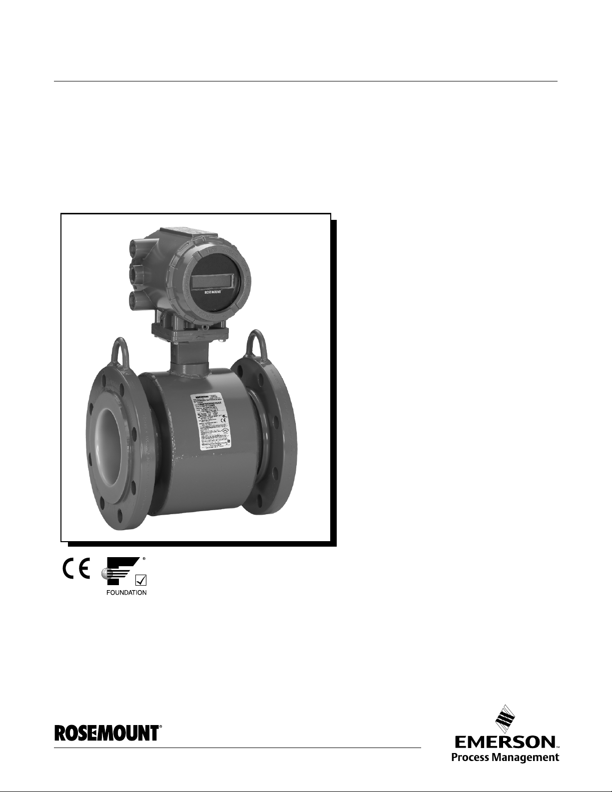
SYSTEM DESCRIPTION The Rosemount
sensor and transmitter, and measures volumetric flow rate by detecting the
velocity of a conductive liquid that passes through a magnetic field.
There are four Rosemount magnetic flowmeter sensors:
• Flanged Rosemount 8705
• Flanged High-Signal Rosemount 8707
• Wafer-Style Rosemount 8711
• Sanitary Rosemount 8721
There are two Rosemount magnetic flowmeter transmitters:
• Rosemount 8712
• Rosemount 8732
The sensor is installed in-line with process piping — either vertically or
horizontally. Coils located on opposite sides of the sensor create a magnetic
field. Electrodes located perpendicular to the coils make contact with the
process fluid. A conductive liquid moving through the magnetic field
generates a voltage at the two electrodes that is proportional to the flow
velocity.
The transmitter drives the coils to generate a magnetic field, and electronical ly
conditions the voltage detected by the electrodes to provide a flow signal. T he
transmitter can be integrally or remotely mounted from the sensor.
This manual is designed to assist in the installation and ope ration of the
Rosemount 8732 Magnetic Flowmeter Transmitter and the Rosemount 8700
Series Magnetic Flowmeter Sensors.
®
8700 Series Magnetic Flowmeter System consists of a
www.rosemount.com
Page 12
Reference Manual
See “Safety Messages” on page D-1 for complete warning information.
00809-0100-4663, Rev BA
Rosemount 8732
January 2010
SAFETY MESSAGES Procedures and instructions in this manual may require special preca utions to
ensure the safety of the personnel performing the operations. Refer to the
safety messages listed at the beginning of each section before performing
any operations.
Attempting to install and operate the Rosemount 8705, 8707 High-Signal, 8711 or 8721
Magnetic Sensors with the Rosemount 8712 or 8732 Magnetic Flowmeter Transmitter
without reviewing the instructions contained in this manual could result in personal injury or
equipment damage.
SERVICE SUPPORT To expedite the return process outside the United States, contac t the nearest
Rosemount representative.
Within the United States and Canada, call the North American Response
Center using the 800-654-RSMT (7768) toll-free number. The Response
Center, available 24 hours a day, will assist you with any needed information
or materials.
The center will ask for product model and serial numbers, and will provide a
Return Material Authorization (RMA) number. The center will also ask for the
name of the process material to which the product was last exposed.
Mishandling products exposed to a hazardous subst ance may result in death
or serious injury. If the product being returned was exposed to a hazardous
substance as defined by OSHA, a copy of the required Material Safety Data
Sheet (MSDS) for each hazardous substance identified must be included with
the returned goods.
The North American Response Center will detail the additional information
and procedures necessary to return goods exposed to hazardous
substances.
1-2
Page 13
Reference Manual
00809-0100-4663, Rev BA
January 2010
Section 2 Installation
Safety Messages . . . . . . . . . . . . . . . . . . . . . . . . . . . . . . . . .page 2-1
Transmitter Symbols . . . . . . . . . . . . . . . . . . . . . . . . . . . . . page 2-2
Pre-Installation . . . . . . . . . . . . . . . . . . . . . . . . . . . . . . . . . .page 2-2
Mechanical Considerations . . . . . . . . . . . . . . . . . . . . . . . .page 2-2
Environmental Considerations . . . . . . . . . . . . . . . . . . . . . page 2-3
Installation Procedures . . . . . . . . . . . . . . . . . . . . . . . . . . . page 2-3
Sensor Connections . . . . . . . . . . . . . . . . . . . . . . . . . . . . . . page 2-11
This section covers the steps required to physically install the magnetic
flowmeter. Instructions and procedures in this section may require special
precautions to ensure the safety of the personnel performing the operations.
Please refer to the following safety messages before performing any
operation in this section.
Rosemount 8732
SAFETY MESSAGES This symbol is used throughout this manual to indicate that special attention
to warning information is required.
Failure to follow these installation guidelines could result in death or serious injury:
Installation and servicing instructions are for use by qualified personnel only. Do not perform
any servicing other than that contained in the operating instructions, unless qualified. Verify
that the operating environment of the sensor and transmitter is consistent with the
appropriate hazardous area approval.
Do not connect a Rosemount 8732 to a non-Rosemount sensor that is located in an
explosive atmosphere.
Explosions could result in death or serious injury:
Installation of this transmitter in an explosive environment must be in accordance with the
appropriate local, national, and international standards, codes, and practices. Please review
the approvals section of the 8732 reference manual for any restrictions associated with a
safe installation.
Before connecting a handheld communicator in an explosive atmosphere, make sure the
instruments in the loop are installed in accordance with intrinsically safe or non-incendive
field wiring practices.
Electrical shock can result in death or serious injury
Avoid contact with the leads and terminals. High voltage that may be present on leads can
cause electrical shock.
www.rosemount.com
Page 14
Rosemount 8732
Reference Manual
00809-0100-4663, Rev BA
January 2010
The sensor liner is vulnerable to handling damage. Never place anything through the sensor
for the purpose of lifting or gaining leverage. Liner damage can render the sensor useless.
To avoid possible damage to the sensor liner ends, do not use metallic or spiral-wound
gaskets. If frequent removal is anticipated, take precautions to protect the liner ends. Short
spool pieces attached to the sensor ends are often used for protection.
Correct flange bolt tightening is crucial for proper sensor operation and life. All bolts must be
tightened in the proper sequence to the specified torque limits. Failure to observe these
instructions could result in severe damage to the sensor lining and possible sensor
replacement.
Emerson Process Management can supply lining protectors to prevent liner damage during
removal, installation, and excessive bolt torquing.
TRANSMITTER SYMBOLS
Caution symbol — check product documentation for details
Protective conductor (grounding) terminal
PRE-INSTALLATION Before installing the Rosemount 8732 Magnetic Flowmeter Transmitter, there
are several pre-installation steps that should be completed to make the
installation process easier:
• Identify the options and configurations that apply to your application
• Set the hardware switches if necessary
• Consider mechanical, electrical, an d en vir onm en tal req uir eme nts
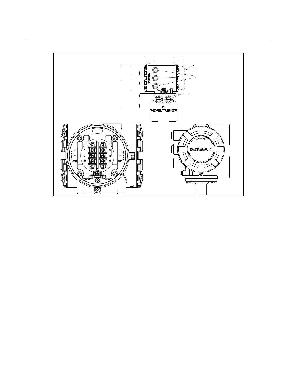
MECHANICAL CONSIDERATIONS
The mounting site for the 8732 transmitter should provide enough room for
secure mounting, easy access to conduit ports, full openin g of the transmitter
covers, and easy readability of the LOI screen (see Figure 2-1). The
transmitter should be mounted in a manner that prevent s moisture in conduit
from collecting in the transmitter.
If the 8732 is mounted remotely from the sensor, it is not subject to limitations
that might apply to the sensor.
2-2
Page 15
Reference Manual
5.82
(148)
6.48 (165)
7.49 (190)
LOI Cover
4.97
(126)
8.81
(224)
3.00
(76)
3.07
(78)
4.97
(126)
1
/2”-14 NPT Electrical
Conduit Connections
(2 places with a 3rd
optional)
1
/2”-14 NPT Remote Junction
Box Conduit Connections (2
places)
00809-0100-4663, Rev BA
January 2010
Figure 2-1. Rosemount 8732 Dimensional Drawing
Rosemount 8732
ENVIRONMENTAL CONSIDERATIONS
To ensure maximum transmitter life, avoid temperature extremes and
vibration. Typical problem areas include:
• high-vibration lines with integrally mounted transmitters
• warm-climate installations in direct sunlight
• outdoor installations in cold climates.
Remote-mounted transmitters may be installed in the control room to protect
the electronics from a harsh environment and provides easy access for
INSTALLATION PROCEDURES
configuration or service.
Rosemount 8732 transmitters require external power so there must be access
to a suitable power source.
Rosemount 8732 installation includes both detailed mecha nical and electrical
installation procedures.
Mount the Transmitter Remote-mounted transmitters may be mounted on a pipe up to two inches in
diameter or against a flat surface.
Pipe Mounting
To mount the transmitter on a pipe:
1. Attach the mounting bracket to the pip e using the m ounting har dware.
2. Attach the 8732 to the mounting bracket using the mounting screws.
2-3
Page 16

Rosemount 8732
Reference Manual
00809-0100-4663, Rev BA
January 2010
Surface Mounting
To surface mount the transmitter:
1. Attach the 8732 to the mounting location using the mounting screws.
Identify Options and Configurations
The standard application of the Rosemount 8732 includes a FOUNDATION
fieldbus output. Be sure to identify options and configurations that apply to
your situation, and keep a list of them nearby for consideration during the
installation and configuration procedures.
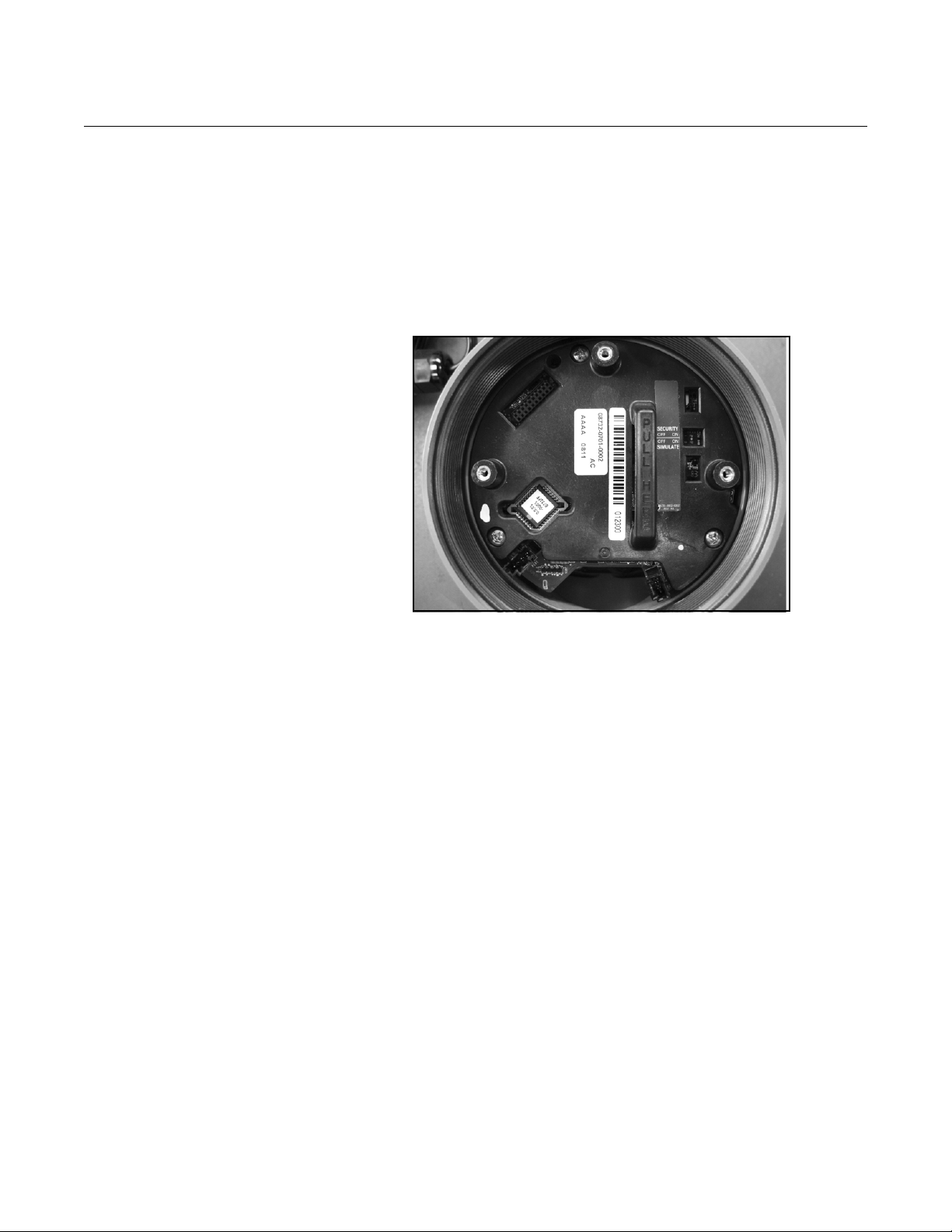
Hardware Switches The 8732 electronics board is equipped with two user-selectable hardware
switches. These switches set the Transmitter Security and Simulate Mode.
The standard configuration for these switches when shipped from the factory
are as follows:
Transmitter Security: OFF
Simulate Mode OFF
Definitions of these switches and their functions are provided below. If you
determine that the settings must be changed, see below .
Transmitter Security
The security switch on the 8732 allows the user to lock out any configuration
changes attempted on the transmitter. No changes to the configuration are
allowed when the switch is in the ON position. The flow rate indication
function remains active at all times.
With the switch in the ON position, you may still access and review any of the
operating parameters and scroll through the available choices, but no actual
data changes are allowed. Transmitter security is set in the OFF position
when shipped from the factory.
Simulate Mode
The Simulate Mode switch is used in conjunction with the Analog Input (AI)
function block. The switch is used to enable flow measurement simulation. To
enable the simulate enable feature, the switch must transition from OFF to
ON after power is applied to the transmitter, preventing the transmitter from
being accidentally left in simulate mode. Simulate Mode is set in the OFF
position when shipped from the factory.
Changing Hardware Switch Settings
In most cases, it is not necessary to change the setting of the hardware
switches. If you need to change the switch settings, complete the steps
below:
NOTE
The hardware switches are located on the top side of the electronics board
and changing their settings requires opening the electronics housing. If
possible, carry out these procedures away from the plant environment in
order to protect the electronics.
2-4
Page 17
Reference Manual
00809-0100-4663, Rev BA
January 2010
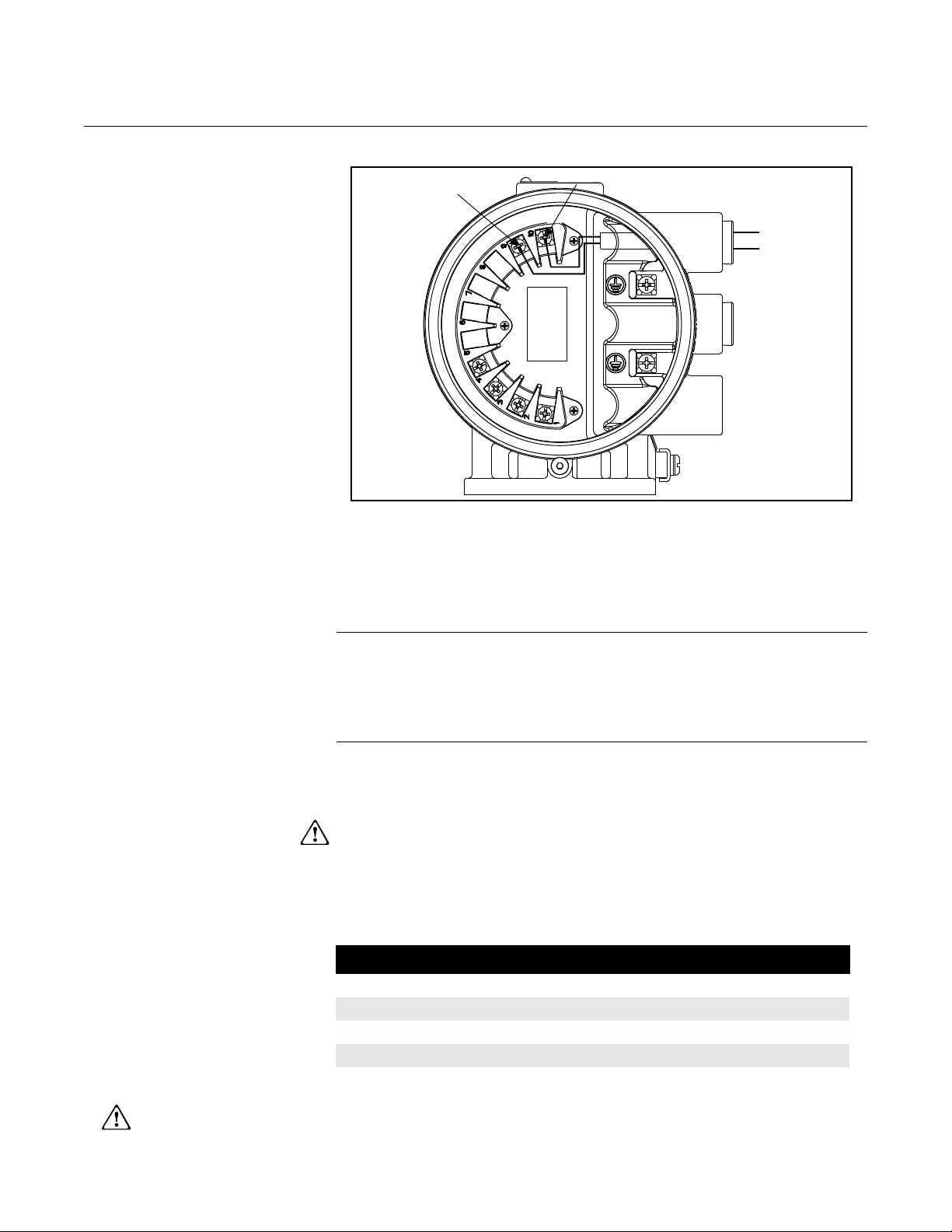
Figure 2-2. Rosemount 8732
Electronics Board and Hardware
Switches
Rosemount 8732
1. Disconnect power to the transmitter.
2. Remove electronics cover.
3. Remove display if applicable.
4. Identify the location of each switch (see Figure 2-2).
5. Change the setting of the desired switche s with a sm all scr ewd r iver.
6. Replace the electronics cover.
Conduit Ports and Connections
Both the sensor and transmitter junction boxes have ports for 1/2-inch NPT
conduit connections, with optional CM20 and PG 13.5 connections available.
These connections should be made in accordance with national, local or plant
electrical codes. Unused ports should be sealed with metal plugs and PTFE
tape or other thread sealant. Connections should also be made in accordance
with area approval requirements, see examples below for details. Proper
electrical installation is necessary to prevent errors due to electrical noise and
interference. Separate conduit s are not necessary for the coil drive and signa l
cables connecting the transmitter to the sensor, but a dedicated conduit line
between each transmitter and sensor is required. A shielded cable must be
used.
Example 1: Installing flanged sensors into an IP68 area. Sensors must be
installed with IP68 cable glands and cable to maintain IP68 rating. Unused
conduit connections must be properly sealed to prevent water ingress. For
added protection, dielectric gel can be used to pot the sensor terminal block.
Example 2: Installing flowmeters into explosion proof/flameproof areas.
Conduit connections and conduit must be rated for use in the hazardous area
to maintain flowmeter approval rating.
2-5
Page 18
Reference Manual
NOTE
Dimensions are in
inches
(millimeters).
1.00
(26)
Cable Shield
00809-0100-4663, Rev BA
Rosemount 8732
January 2010
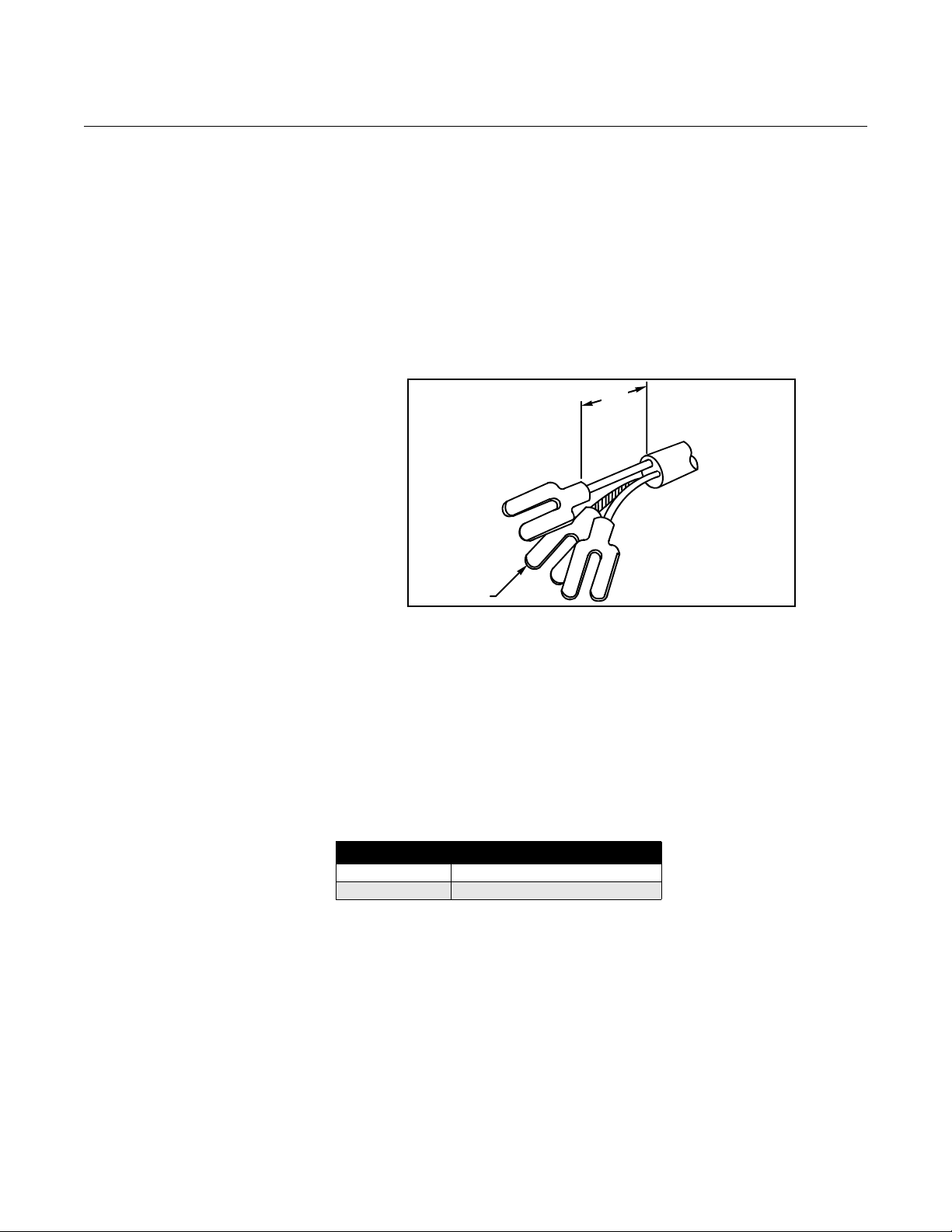
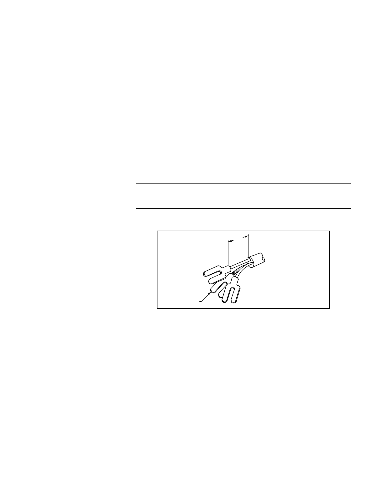
Conduit Cables Run the appropriate size cable through the conduit connections in your
magnetic flowmeter system. Run the power cable from the power source to
the transmitter . Do n ot run power cab les and outpu t signal cables in the same
conduit. For remote mount installations, run the coil drive and electrode
cables between the flowmeter and transmitter. Refer to Electrical
Considerations for wire type. Prepare the ends of the coil drive and electrode
cables as shown in Figure 2-3. Limit the unshielded wire length to 1-in. on
both the electrode and coil drive cables. Excessive lead length or failure to
connect cable shields can create electrical noise resulting in unstable meter
readings.
Figure 2-3. Cable Preparation
Detail
Electrical Considerations Before making any electrical connections to the Rosemount 8732, consider
the following standards and be sure to have th e proper power supply, conduit,
and other accessories. When prepar ing all wir e conne ctions, remove only the
insulation required to fit the wire completely under the terminal connection.
Removal of excessive insulation may result in an unwanted electrical short to
the transmitter housing or other wire connections.
Transmitter Input Power
The 8732 transmitter is designed to be powered b y 90-250 V AC, 50–60 Hz or
12–42 V DC. The eighth digit in the transmitter model number designates the
appropriate power supply requirement.
Model Number Power Supply Requirement
1 90-250 V AC
2 12-42 V DC
Supply Wire Temperature Rating
Use 12 to 18 AWG wire. For connections in ambient temperatures
exceeding 140 °F (60 °C), use wire rated to at least 194 °F (90 °C).
Disconnects
Connect the device through an external disconnect or circuit breaker.
Clearly label the disconnect or circuit breaker and locate it near the
transmitter.
Requirements for 90-250 V AC Power Supply
2-6
Wire the transmitter according to national, local, and plant electrical
requirements for the supply voltage. In addition, follow the supply wire and
disconnect requirements on page2-7.
Page 19
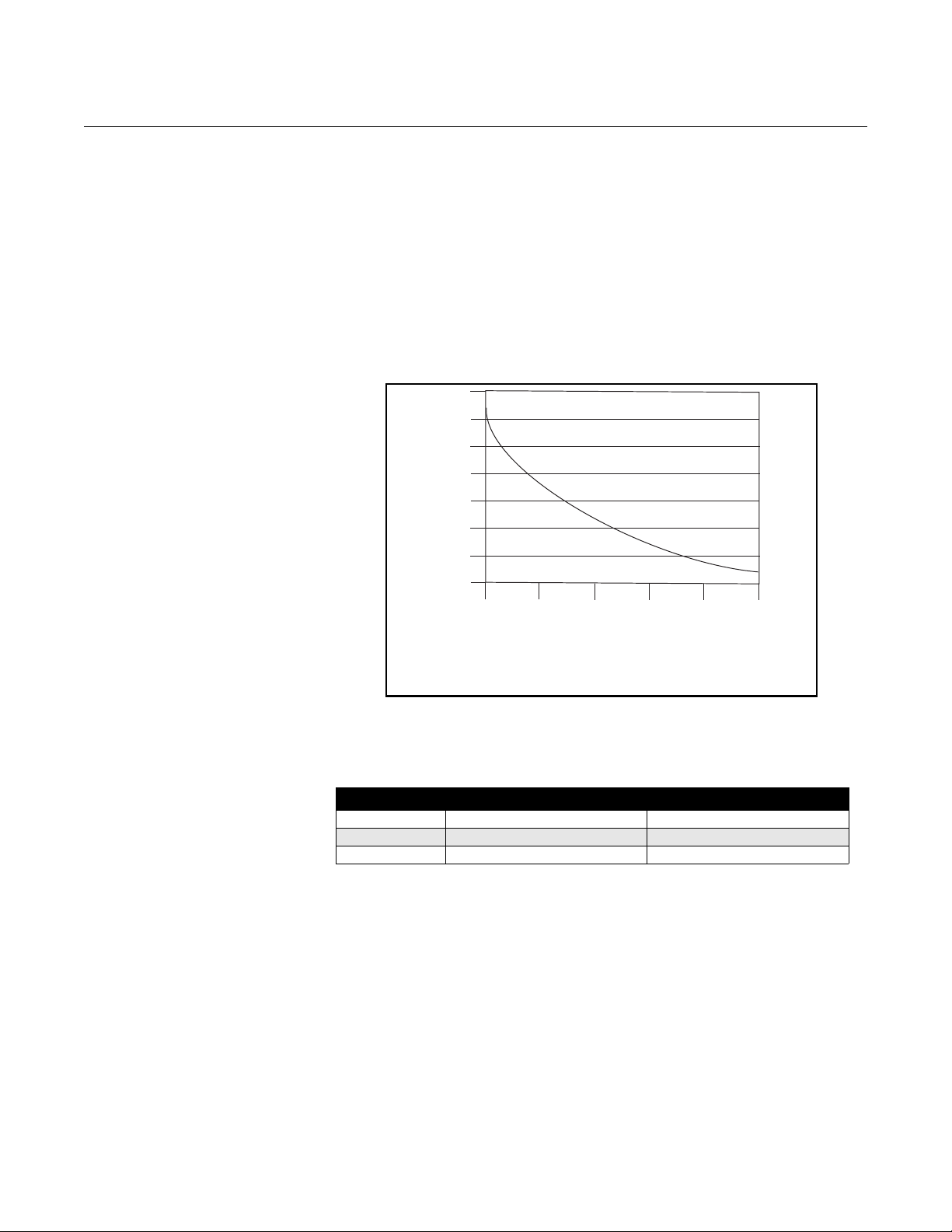
Reference Manual
MaximumResis cetan
SupplyVoltage 12– VDC
1amp
--------------------------------------------------------------------=
Power Supply (Volts)
I = 10/V
I = Supply current requirement (Amps)
V = Power supply voltage (Volts)
Supply Current (Amps)
12 18
24
30
36
42
0.2
0.3
0.4
0.5
0.6
0.7
0.8
0.9
00809-0100-4663, Rev BA
January 2010
Figure 2-4. Supply Current
versus Input Voltage
Rosemount 8732
Requirements for 12-42 V DC Power Supply
Units powered with 12-42 V DC may draw up to 1 amp of cu rren t. As a result,
the input power wire must meet certain gauge requirements.
Figure 2-4 shows the supply current for each corresponding supply voltage .
For combinations not shown, you can calculate the maximum distance given
the supply current, the voltage of the source, and the minimum start-up
voltage of the transmitter, 12 V DC, using the following equation:
Installation Category The installation category for the Rosemount 87 32 is (overvoltage) Category II. Overcurrent Protection The Rosemount 8732 Flowmeter Transmitter requires overcurrent protection
of the supply lines. Maximum ratings of overcurrent devices are as follows:
Power System Fuse Rating Manufacturer
110 V AC 250 V; 1 Amp, Quick Acting Bussman AGCI or Equivalent
220 V AC 250 V; 2 Amp, Quick Acting Bussman AGCI or Equivalent
42 V DC 50 V, 3 Amp, Quick Acting Bussman AGCI or Equivalent
Connect Transmitter Power
To connect power to the transmitter, complete the following steps.
1. Ensure that the power source and connecting cable meet the
requirements outlined on page 2-8.
2. Turn of f the power source.
3. Open the power terminal cover.
4. Run the power cable through the conduit to the transmitter.
5. Connect the power cable leads as shown in Figure 2-5.
a. Connect AC Neutral or DC- to terminal 9.
b. Connect AC Line or DC+ to terminal 10.
c. Connect AC Ground or DC Ground to the ground screw mounted
inside the transmitter enclosure.
2-7
Page 20
Rosemount 8732
AC Line or DC +
Transmitter
Power Cable
AC Neutral or DC –
AC or DC
Ground
See “Safety Messages” on page 2-1 for complete warning information.
Figure 2-5. AC Transmitter
Power Connections
Reference Manual
00809-0100-4663, Rev BA
January 2010
Connect FOUNDATION fieldbus Wiring
Transmitter Communication Input
Power Conditioning Each fieldbus power supply requires a power conditioner to decouple the
Field Wiring Power independent of the coil power supply must be supplied for FOUNDATION
Table 2-1.
Ideal Cable Specifications for
Fieldbus Wiring
The FOUNDATION fieldbus signal provides the output information from the
transmitter.
The FOUNDATION fieldbus communication requires a minimum of
9 V dc and a maximum of 32 V dc at the transmitter communication terminals.
NOTES
• Do not exceed 32 V dc at the transmitter communication terminals.
• Do not apply ac line voltage to the transmitter
communication terminals.
Improper supply voltage can damage the transmitter.
power supply output from the fieldbus wiring segment.
fieldbus communications. Use shielded, twisted pair for best results. For new
installations or to get maximum performance, twisted pair cable designed
especially for fieldbus should be used. Table 2-1 details cable characteristics
and ideal specifications.
Characteristic Ideal Specification
Impedance 100 Ohms ± 20% at 31.25 kHz
Wire Size 18 AWG (0,8 mm2)
Shield Coverage 90%
Attenuation 3 db/km
Capacitive Unbalance 2 nF/km
2-8
Page 21
Reference Manual
–FF signal
+FF signal
00809-0100-4663, Rev BA
January 2010
Rosemount 8732
NOTE
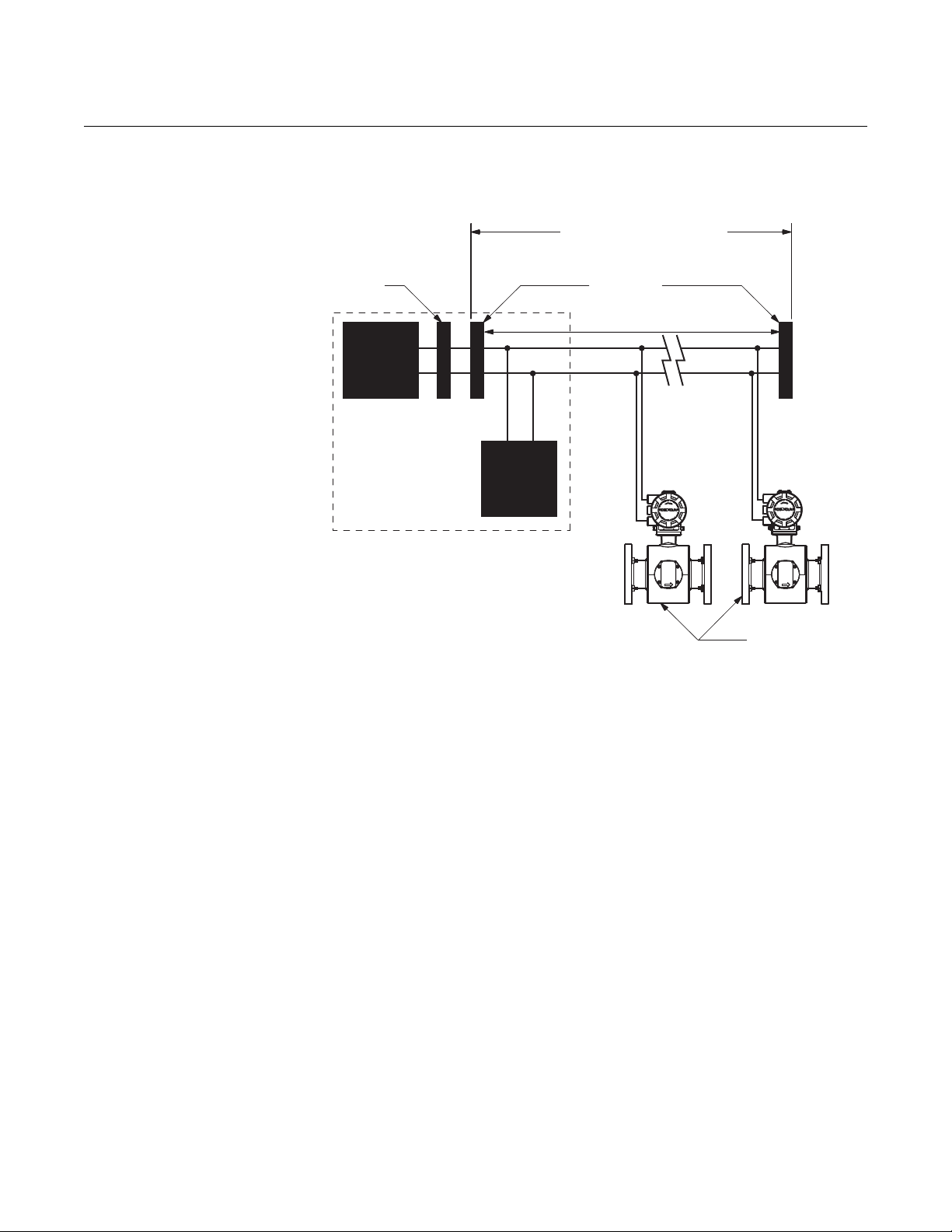
The number of devices on a fieldbus segment is limited by the power supply
voltage, the resistance of the cable, and the amount of current drawn by
each device.
Transmitter Wiring Connection
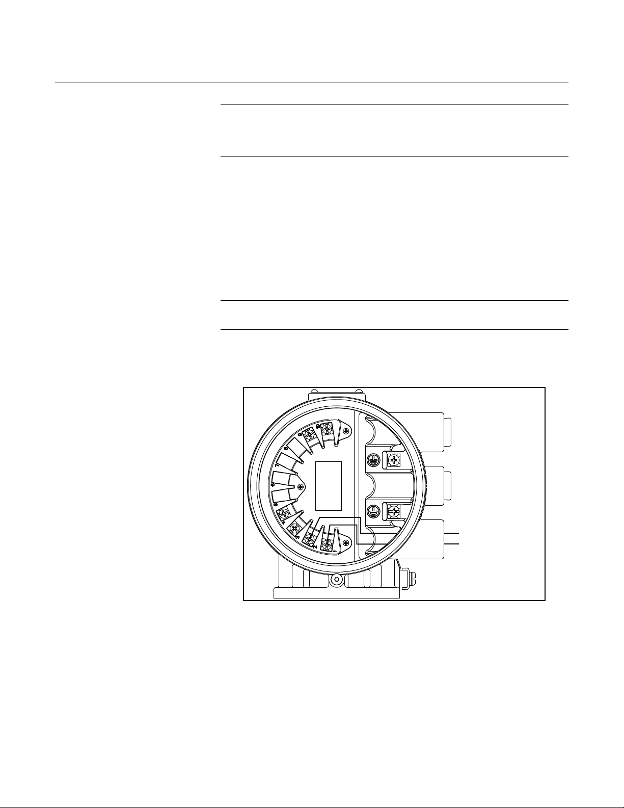
Figure 2-6. F
Signal Connections
OUNDATION fieldbus
To connect the 8732 to the FOUNDATION fieldbus (FF) segment, complete
the following steps.
1. Ensure that the power source and connecting cable meet the
requirements outlined above and in “Field Wiring” on page 2-8.
2. Turn of f the transmitter and power sources.
3. Run the F
4. Connect -FF to Terminal 1.
5. Connect +FF to Terminal 2.
NOTE
Foundation fieldbus signal wiring for the 8732 is not polarity sensitive.
Refer to Figure 2-6 on page 2-9.
OUNDATION fieldbus cable into the transmitter.
2-9
Page 22
Rosemount 8732
Integrated
Power
Conditioner
and Filter
Terminators
6234 ft (1900 m) max
(depending upon cable
characteristics)
Fieldbus
Segment
(Spur)
(Trunk)
(The power supply,
filter, first terminator,
and configuration tool
are typically located
in the control room.)
*Intrinsically safe installations may
allow fewer devices per I.S. barrier.
Power
Supply
FOUNDATION
Fieldbus
Configuration
Tool
(Spur)
Devices 1 through 11*
Figure 2-7. Rosemount 8732
Transmitter Field Wiring
Reference Manual
00809-0100-4663, Rev BA
January 2010
2-10
Page 23
Reference Manual
Coil Drive
and
Electrode
Cables
Power
Power
Outputs
Outputs
Coil Drive
and
Electrode
Cables
Power
Outputs
Power
Outputs
00809-0100-4663, Rev BA
January 2010
Rosemount 8732
SENSOR CONNECTIONS This section covers the steps required to physically install the transmitter
including wiring and calibration.
Rosemount Sensors To connect the transmitter to a non-Rosemount sensor, refer to the
appropriate wiring diagram in “Universal Sensor Wiring Diagrams” on
page E-1. The calibration procedure listed is not required for use with
Rosemount sensors.
Transmitter to Sensor Wiring
Figure 2-8. Conduit Preparation
Correct Incorrect
Flanged and wafer sensors have two conduit ports as shown in Figur e 2-8.
Either one may be used for both the coil drive and electrode cables. Use the
stainless steel plug that is provided to seal the unused conduit port. Use
Teflon tape or thread sealant appropriate for the installation when sealing the
conduit.
A single dedicated conduit run for the coil drive and electrode cables is
needed between a sensor and a remote transmitter. Bundled cables in a
single conduit are likely to create interference and noise problems in your
system. Use one set of cables per conduit run. See Figure 2-8 for proper
conduit installation diagram and Table 2-2 for recommended cable. For
integral and remote wiring diagrams refer to Figure 2-10.
Table 2-2. Cable Requirements
Description Units Part Number
Signal Cable (20 AWG) Belden 8762, Alpha 2411 equivalent ft
Coil Drive Cable (14 AWG) Belden 8720, Alpha 2442 equivalent ft
Combination Signal and Coil Drive Cable (18 AWG)
(1) Combination signal and coil drive cable is not recommended for high-signal magmeter system. For remote mount installa tions, combination signal and coil
(1)
drive cable should be limited to less than 330 ft. (100 m).
08712-0061-0001
m
m
ft
m
08712-0061-0003
08712-0060-0001
08712-0060-0003
08712-0752-0001
08712-0752-0003
2-11
Page 24
Reference Manual
1.00
(26)
NOTE
Dimensions are in
inches (millimeters).
Cable Shield
00809-0100-4663, Rev BA
Rosemount 8732
January 2010
Rosemount recommends using the combination signal and coil drive for N5,
E5 approved sensors for optimum performance.
Remote transmitter installations require equal lengths of signal and coil drive
cables. Integrally mounted transmitters are factory wired and do not require
interconnecting cables.
Lengths from 5 to 1,000 feet (1.5 to 300 meters) may be specified, and will be
shipped with the sensor.
Conduit Cables Run the appropriate size cable through the conduit connections in your
magnetic flowmeter system. Run the power cable from the power source to
the transmitter. Run the coil drive and electrode cables between the sensor
and transmitter .
Prepare the ends of the coil drive and electrode cables as shown in Figure
2-9. Limit the unshielded wire length to 1-inch on both the electrode and coil
drive cables.
NOTE
Excessive lead length or failure to connect cable shields ca n create electrical
noise resulting in unstable meter readings.
Figure 2-9. Cable Preparation
Detail
2-12
Page 25
Reference Manual
00809-0100-4663, Rev BA
January 2010
Rosemount 8732
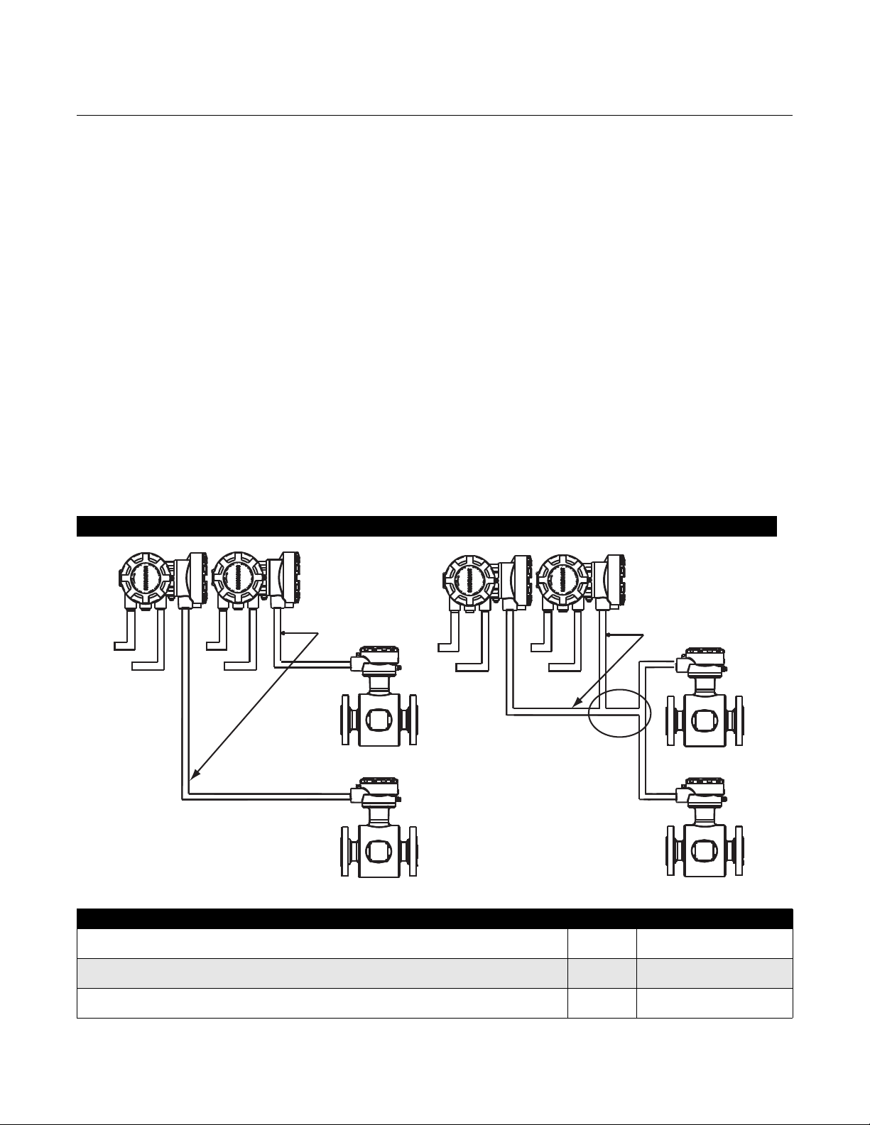
Sensor to Remote Mount Transmitter Connections
Figure 2-10. Wiring Diagram
Connect coil drive and electrode cables as shown in Figure 2-10.
Do not connect AC power to the sensor or to terminals 1 an d 2 of the
transmitter, or replacement of the electronics board will be necessary.
Rosemount 8732 Transmitter
11
2 2
17 17
18 18
19 19
Rosemount 8705/8707/8711/8721
Sensors
2-13
Page 26

Rosemount 8732
Reference Manual
00809-0100-4663, Rev BA
January 2010
2-14
Page 27
Reference Manual
00809-0100-4663, Rev BA
January 2010
Rosemount 8732
Section 3 Configuration
Introduction . . . . . . . . . . . . . . . . . . . . . . . . . . . . . . . . . . . . . page 3-1
Local Operator Interface . . . . . . . . . . . . . . . . . . . . . . . . . . page 3-1
Basic Features . . . . . . . . . . . . . . . . . . . . . . . . . . . . . . . . . . page 3-1
LOI Examples . . . . . . . . . . . . . . . . . . . . . . . . . . . . . . . . . . .page 3-2
Diagnostic Messages . . . . . . . . . . . . . . . . . . . . . . . . . . . . . page 3-5
Process Variables . . . . . . . . . . . . . . . . . . . . . . . . . . . . . . . .page 3-5
Basic Setup . . . . . . . . . . . . . . . . . . . . . . . . . . . . . . . . . . . . .page 3-7
INTRODUCTION This section covers basic operation, software functionality, and configuration
procedures for the Rosemount 8732 Magnetic Flowmeter Transmitter. For
information on connecting anothe r m anufacturer’s flowtube sensor, refer to
“Universal Sensor Wiring Diagrams” on page E-1.
The Rosemount 8732 features a full range of software functions for
configuration of output from the transmitter. Software functions are accessed
through the LOI, AMS, a Handheld Communicator, or a control system.
Configuration variables may be changed at any time and specific instructions
are provided through on-screen instructions.
Table 3-1. Parameters
Basic Set-up Parameters Page
Review page 3-5
Process Variables page 3-5
Basic Setup page 3-7
Flow Units page 3-7
Range Values page 3-10
PV Sensor/Flowtube Sensor Calibration Number page 3-11
Totalizer Setup page 3-6
LOCAL OPERATOR INTERFACE
The optional Local Operator Interface (LOI) provides an operator
communications center for the 8732. By using th e LO I, th e op er at or can
access any transmitter function for changing configuration parameter settings,
checking totalized values, or other functions. The LOI is integral to the
transmitter electronics.
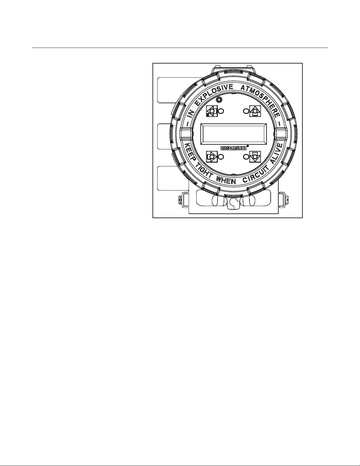
BASIC FEATURES The basic features of the LOI include 4 navigational arrow keys that are used
to access the menu structure. See Figure 3-1.
www.rosemount.com
Page 28
Rosemount 8732
Figure 3-1. Local Operator
Interface Keypad
Reference Manual
00809-0100-4663, Rev BA
January 2010
Data Entry The LOI keypad does not have numerical keys. Numerical data is entered by
the following procedure.
1. Access the appropriate function.
2. Use the RIGHT ARROW key to move to the value to change.
3. Use the UP and DOWN ARROWS to change the highlighted value.
For numerical data, toggle through the digits 0–9, decimal point, and
dash. For alphabetical data, toggle through the letters of the alphabet
A–Z, digits 0–9, and the symbols ,&, +, -, *, /, $, @,%, and the blank
space.
4. Use the RIGHT ARRO WS to highlight other digit s you want to change
and change them.
5. Press “E” (the lef t arrow key) when all cha nges are compl ete to save
the entered values.
LOI EXAMPLES Use the DOWN ARROW to access the menu structure in Table 3-2. Use the
ARROW KEYS to select the desired parameters to review/change.
Parameters are set in one of two ways, Table Values or Select Values.
Table Values:
Parameters such as units, that are available from a predefined list
Select Values:
Parameters that consist of a user-created number or character string, such
as calibration number; values are entered one character at a time using
the ARROW KEYS.
3-2
Page 29

Reference Manual
00809-0100-4663, Rev BA
January 2010
Table Value Example Setting the TUBE SIZE:
1. Press the DOWN arrow to access the menu.
2. Select line size from the Basic set-up menu.
3. Press the UP or DOWN arrow to increase/decrease (incrementally)
the tube size to the next value.
4. When you reach the desired size, press “E” (the left arrow).
5. Set the loop to manual if necessary, and press “E” again.
After a moment, the LCD will display the new tube size and the maximum flow
rate.
Select Value Example Changing the ANALOG OUTPUT RANGE:
1. Press the DOWN arrow to access the menu.
2. Using the arrow keys, select PV URV from the Basic Setup menu.
3. Press RIGHT arrow key to posit ion the cursor.
4. Press UP or DOWN to set the number.
5. Repeat steps 2 and 3 until desired number is displayed.
6. Press “E”.
Rosemount 8732
After a moment, the LCD will display the new analog output range.
Display Lock The display can be locked to prevent unintentional configuration changes.
The display lock can be activated through a HART communication device, or
by holding the UP arrow for 10 seconds. When the display lock is activated,
DL will appear in the lower left hand corner of the display. To deactivate the
display lock (DL), hold the UP arrow for 10 seconds. Once deactivated, the
DL will no longer appear in the lower left hand corner of the display.
Start Totalizer To start the totalizer, press the DOWN arrow to display the totalizer screen
and press “E” to begin totalization. A symbol will flash in the lower right
hand corner indicating that the meter is totalizing.
Stop Totalizer To stop the totalizer, press the DOWN arrow to display the totalizer screen
and press “E” to end totalization. The flashing symbol will no longer display
in the lower right hand corner indicating that the meter has stopped totalizing.
Reset Totalizer To reset the totalizer, press the DOWN arrow to display the totalizer screen
and follow the procedure above to stop totalization. Once totalization has
stopped, press the RIGHT arrow key to reset the NET total value to zero.
To reset the gross total value, you must change the line size. See “Line Size”
on page 3-9 for details on how to change the line size.
3-3
Page 30
Rosemount 8732
Diag Controls
Basic Diag
A dvanced D iag
Variables
Trims
Status
E mpty P ipe
Process Noise
G round/W i ri ng
Elec Temp
Self Test
A O L oop Test
Pulse Out Test
E mpty P ipe
Elec Temp
G round/W i ri ng
Process Noise
8714i
4-20 mA V erif y
Licensing
R un 8714i
V iew Results
Tube Signature
Test Criteria
M easur ements
Values
R e-Signature
Recall V alues
Coil R esist
C oil S ignature
E lectr ode R es
No Flow
Flowing, Full
E mpty P ipe
Coil R esist
C oil S ignature
E lectr ode R es
E mpty P ipe
Elec Temp
L ine N oise
5Hz SN R
37Hz SN R
Signal Power
8714i R esults
D/A Trim
Digital Trim
A uto Z ero
Universal Trim
4-20 mA V erif y
View Results
Tag
Flow Units
L ine S ize
PV UR V
PV L R V
Cal Number
PV Damping
C oi l F requency
Proc Density
PV LSL
PV USL
PV Min Span
Analog
Pulse
DI/DO Config
Totalizer
Reverse Flow
HART
PV UR V
PV L R V
Alarm Type
Test
Pulse Scaling
Pulse W idth
Pulse M ode
Test
DI 1
DO 2
Totalize Units
Total Dis
play
Burst Mode
B urst C ommand
F lange T ype
F lange M atl
E lectr ode T ype
E lectr ode M atl
L iner Material
Software Rev
Final A smbl #
Tag
Description
Message
Device ID
PV Sensor S/N
Flowtube Tag
Revision Num
M ateri al s
Operating Mode
SP Config
C oi l F requenc y
PV Damping
Lo-Flow Cuto
Flow Display
Total Display
L anguage
More Params
Output C onfi g
LOI Config
Si g Processing
Device Info
PV Units
Special Units
Totalize Units
Diagnostics
Basic Setup
Detailed S etup
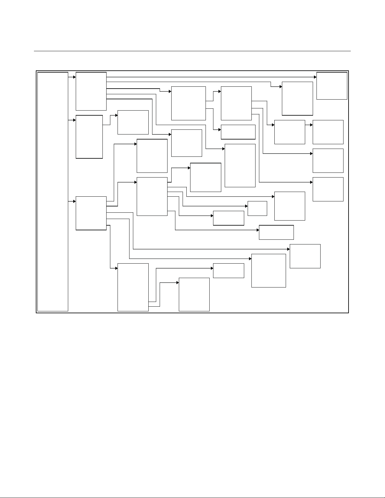
Ta ble 3-2. LOI Menu Tree
Reference Manual
00809-0100-4663, Rev BA
January 2010
3-4
Page 31

Reference Manual
00809-0100-4663, Rev BA
January 2010
Rosemount 8732
DIAGNOSTIC MESSAGES
The following error messages may appear on the LOI screen. See Table 6-4
on page 6-5 for potential causes and corrective actions for these errors:
• Electronics Failure
• Coil open circuit
• Digital trim failure
• Auto zero failure
• Auto trim failure
• Flowrate > sensor limit
• Analog out of range
• PZR activated
• Electronics Temp Fail
• Pulse out of range
• Empty pipe
• Reverse flow
• Electronics temp out of range
The following error messages may appear on the LOI screen. See Table 6-4
on page 6-5 for potential causes and corrective actions for these errors:
• High Process Noise
• Grounding/Wiring Fault
• 4-20 mA Loop Verification Failed
• 8714i Failed
Review The 8732 includes a capability that enables you to review the configuration
Fast Keys 1, 5
variable settings.
The flowmeter configuration parameters set at the factory should be reviewed
to ensure accuracy and compatibility with your particular application of the
flowmeter.
NOTE
If you are using the LOI to review variables, each variable must be accessed
as if you were going to change its setting. The value displayed on the LOI
screen is the configured value of the variable.
PROCESS VARIABLES The process variables measure flow in several ways that reflect your needs
Fast Keys 1, 1
and the configuration of your flowmeter. When commissioning a flowmeter,
review each process variable, its function and output, and take co rrective
action if necessary before using the flowmete r in a proc es s application
Process Variable (PV) – The actual measured flow rate in the line. Use the
Process Variable Units function to select the units for yourapplication.
Percent of Range – The process variable as a percentage of the Analog
Output range, provides an indication where the current flow of the meter is
within the configured range of the flowmeter. For example, the Analog Output
range may be defined as 0 gal/min to 20 gal/min. If the measured flow is 10
gal/min, the percent of range is 50 percent.
3-5
Page 32

Reference Manual
00809-0100-4663, Rev BA
Rosemount 8732
Analog Output – The analog output variable provides the analog value fo r the
flow rate. The analog output refers to the industry stand ard output in th e 4–20
mA range. The analog output and 4-20 mA loop can be verified using the
Analog Feedback diagnostic capability internal to the transmitter (See “8714i
Meter Verification” on page C-8).
Totalizer Setup – Provides a reading of the total flow of the flowmeter since the totalizer was last reset. The totalizer value should be zero during commissioning on the bench, and the units should reflect the volume units of the flow rate. If the totalizer value is not zero, it may need to be reset. This function also allows for configuration of the totalizer parameters.
Pulse Output – The pulse output variable provides the pulse value for the flow
rate.
January 2010
PV - Primary Variable The Primary Variable shows the current measured flow rate. This value
Fast Keys 1, 1, 1
determines the analog output from the transmitter.
PV -% Range The PV% Range shows where in the flow range the current flow value is as a
Fast Keys 1, 1, 2
percentage of the configured span.
PV - Analog Output The PV Analog Output displays the mA output of the transmitter
Fast Keys 1, 1, 3
corresponding to the measured flow rate.
Totalizer Setup The Totalizer Setup menu allows for the viewing and configuration of the
Fast Keys 1, 1, 4
totalizer parameters.
Totalizer Units
Fast Keys 1, 1, 4, 1
Totalizer units allow for the configuration of the units that the totalized value
will be displayed as. These units are independent of the flow units.
Measured Gross Total
Fast Keys 1, 1, 4, 2
Measured gross total provides the output reading of the tot alizer. This value is
the amount of process fluid that has passed through the flowmeter since the
totalizer was last reset.
NOTE
To reset the measured gross total value, the line size must be changed.
Measured Net Total
Fast Keys 1, 1, 4, 3
Measured net total provides the output reading of the totalizer. This value is
the amount of process fluid that has passed through the flowmeter since the
totalizer was last reset. When re verse flow is enabled, the net tot al represent s
the difference between the total flow in the forward dir ection less the tot al flow
in the reverse direction.
3-6
Page 33

Reference Manual
00809-0100-4663, Rev BA
January 2010
Rosemount 8732
Measured Reverse Total
Fast Keys 1, 1, 4, 4
Measured reverse total provides the output reading of th e tota lizer. This value
is the amount of process fluid that has passed through the flowmeter in the
reverse direction since the totalizer was last reset. This value is only totalized
when reverse flow is enabled.
Start Totalizer
Fast Keys 1, 1, 4, 5
Start totalizer starts the totalizer counting from its current value.
Stop Totalizer
Fast Keys 1, 1, 4, 6
Stop totalizer in terrupts the totalizer count until it is restarted again. This
feature is often used during pipe cleaning or other mainte na nce operations.
Reset Totalizer
Fast Keys 1, 1, 4, 7
Reset totalizer resets the net totalizer value to zero. The totalizer must be
stopped before resetting.
NOTE
The totalizer value is saved in the Non-Volatile memory of the electronics
every three seconds. Should power to the transmitter be interrupted, the
totalizer value will start at the last saved value when power is re-applied.
Pulse Output The Pulse Output displays the current value of the pulse signal.
Fast Keys 1, 1, 5
BASIC SETUP The basic configuration functions of the Rosemount 8732 must be set for all
Fast Keys 1, 3
applications of the transmitter in a magnetic flowmeter system. If your
application requires the advanced functionality features of the Rosemount
8732, see Section 4 "Operation" of this manual.
Tag Tag is the quickest and shortest way of identifying and distinguishing between
Fast Keys 1, 3, 1
transmitters. Transmitters can be tagged according to the requirements of
your application. The tag may be up to eight characters long.
Flow Units Flow Units set the output units for the Primary Variable which controls the
Fast Keys 1, 3, 2
analog output of the transmitter.
Primary Variable Units
Fast Keys 1, 3, 2, 1
The Primary Variable Units specifies the format in which the flow rate will be
displayed. Units should be selected to meet your particular metering needs.
3-7
Page 34

Rosemount 8732
Reference Manual
00809-0100-4663, Rev BA
January 2010
Options for Flow Rate Units
• ft/sec • B31/sec (1 Barrel = 31.5 gallons)
•m/sec • B31/min (1 Barrel = 31.5 gallons)
• gal/sec • B31/hr (1 Barrel = 31.5 gallons)
• gal/min • B31/day (1 Barrel = 31.5 gallons)
• gal/hr • lbs/sec
• gal/day •lbs/min
•l/sec •lbs/hr
•l/min • lbs/day
• l/hr • kg/sec
• l/day •kg/min
3
•ft
/sec • kg/hr
•ft3/min • kg/day
3
/hr • (s)tons/min
•ft
•ft3/day • (s)tons/hr
3
/sec • (s)tons/day
•m
•m3/min • (m)tons/min
3
/hr • (m)tons/hr
•m
•m3/day • (m)tons/day
• Impgal/sec • Special (User Defined, see
• Impgal/min
• Impgal/hr
• Impgal/day
• B42/sec (1 Barrel = 42 gallons)
• B42/min (1 Barrel = 42 gallons)
• B42/hr (1 Barrel = 42 gallons)
• B42/day (1 Barrel = 42 gallons)
“Special Units” on page 3-8)
3-8
Special Units
Fast Keys 1, 3, 2, 2
The Rosemount 8732 provides a selection of standard u nit configurations that
meet the needs of most applications (see “Flow Units” on page 3-7). If your
application has special needs and the standard configurations do not apply,
the Rosemount 8732 provides the flexibility to configure the transmitter in a
custom-designed units format using the special units variable.
Special Volume Unit
Fast Keys 1, 3, 2, 2, 1
Special volume unit enables you to display the volume unit format to which
you have converted the base volume units. For example, if the special units
are abc/min, the special volume variable is abc. The volume units variable is
also used in totalizing the special units flow.
Page 35

Reference Manual
00809-0100-4663, Rev BA
January 2010
Rosemount 8732
Base Volume Unit
Fast Keys 1, 3, 2, 2, 2
Base volume unit is the unit from which the conversion is being made. Set this
variable to the appropriate option.
Conversion Number
Fast Keys 1, 3, 2, 2, 3
The special units conversion number is used to convert base units to special
units. For a straight conversion of volume units from one to another, the
conversion number is the number of base units in the new unit. For example,
if you are converting from gallons to barrels and there are 31 gallons in a
barrel, the conversion factor is 31.
Base Time Unit
Fast Keys 1, 3, 2, 2, 4
Base time unit provides the time unit from which to calculate the special units.
For example, if your special units is a volume per minute, select minutes.
Special Flow Rate Unit
Fast Keys 1, 3, 2, 2, 5
Special flow rate unit is a format variable that provides a record of the units to
which you are converting. The Handheld Communicator will display a special
units designator as the units format for your primary variable. The actual
special units setting you define will not appear. Four characters are available
to store the new units designation. The 8732 LOI will display the four
character designation as configured.
Example
To display flow in barrels per hour, and one barrel is equal to 31.0 gallons, the
procedure would be:
Set the Volume Unit to BARL.
Set the Base Volume Unit to gallons.
Set the Input Conversion Number to 31.
Set the Time Base to Hour.
Set the Rate Unit to BR/H.
Line Size The line size (flowtube sensor size) must be set to match the actual flowtube
Fast Keys 1, 3, 3
sensor connected to the transmitter. The size must be specified in inches
according to the available sizes listed below. If a value is entered from a
control system or Handheld Communicator that does not match one of these
figures, the value will go to the next highest option.
The line size (inches) options are as follows:
0.1, 0.15, 0.25, 0.30, 0.50, 0.75, 1, 1.5, 2, 2.5, 3, 4, 6, 8, 10, 12, 14,
16, 18, 20, 24, 28, 30, 32, 36, 40, 42, 44, 48, 54, 56, 60, 64, 72, 80
3-9
Page 36

Rosemount 8732
Reference Manual
00809-0100-4663, Rev BA
January 2010
PV URV (Upper Range Value)
Fast Keys 1, 3, 4
PV LRV (Lower Range Value)
Fast Keys 1, 3, 5
The upper range value (URV), or analog output range, is preset to 30 ft/s at
the factory . The units that appear will be the same as those selected under the
units parameter.
The URV (20 mA point) can be set for both forward or reverse flow rate. Flow
in the forward direction is represented by positive values and flow in the
reverse direction is represented by negative values. The URV can be any
value from –39.3 ft/s to +39.3 ft/s (-12 m/ s to +12 m/s) , as long as it is at least
1 ft/s (0.3 m/s) from the lower range value (4 mA point). The URV can be set
to a value less than the lower range value. This will cause the transmitter
analog output to operate in reverse, with the current increasing for lower (or
more negative) flow rates.
NOTE
Line size, special units, and density must be selected prior to configuration of
URV and LRV.
Set the lower range value (LRV), or analog output zer o, to change the size of
the range (or span) between the UR V an d LR V. Under normal circumstances,
the LRV should be set to a value near the minimum expected flow rate to
maximize resolution. The LRV must be between
–39.3 ft/s to +39.3 ft/s (-12 m/s to +12 m/s).
NOTE
Line size, special units, and density must be selected prior to configuration of
URV and LRV.
Example
If the URV is greater than the LRV, the analog output will saturate at 3.9 mA
when the flow rate falls below the selected 4 mA point.
The minimum allowable span between the URV and LRV is 1 ft/s (0.3 m/s).
Do not set the LRV within 1 ft/s (0.3 m/s) of the 20 mA point. For example, if
the URV is set to 15.67 ft/s (4.8 m/s) and if the desired URV is greater than
the LRV, then the highest allowable analog zero setting would be 14.67 ft/s
(4.5 m/s). If the desired URV is less than the LRV, then the lowest allowable
LRV would be 16.67 ft/s (5.1 m/s).
3-10
Page 37

Reference Manual
00809-0100-4663, Rev BA
January 2010
Rosemount 8732
Calibration Number The tube calibration number is a 16-digit number used to identify flowtube
Fast Keys 1, 3, 6
sensors calibrated at the Rosemount factory. The calibration number is also
printed inside the flowtube sensor terminal block or on the flowtube sensor
name plate. The number provides detailed calibration information to the
Rosemount 8732. To function properly within accuracy specifications, the
number stored in the transmitter must match the calibration number on the
flowtube sensor exactly.
NOTE
Flowtube Sensors from manufacturers other than Rosemount Inc. can also be
calibrated at the Rosemount factory. Check the tube for Rosemount
calibration tags to determine if a 16-digit tube calibration number exists for
your flowtube sensor.
NOTE
Be sure the calibration number reflects a calibration to a Rosemount
reference transmitter. If the calibration number was generated by a means
other than a certified Rosemount flow lab, accuracy of the system may be
compromised.
If your flowtube sensor is not a Rosemount flowtube sensor and was not
calibrated at the Rosemount factory, contact your Rosemount representative
for assistance.
If your flowtube sensor is imprinted with an eight-digit number or a k-factor,
check in the flowtube sensor wiring compartment for the sixteen-digit
calibration number. If there is no serial number, contact the factory for a
proper conversion.
PV Damping Adjustable between 0.0 and 256 seconds
Fast Keys 1, 3, 7
PV Damping allows selection of a response time, in seconds, to a step change in flow rate. It is most often used to smooth fluctuations in output.
3-11
Page 38

Rosemount 8732
Reference Manual
00809-0100-4663, Rev BA
January 2010
3-12
Page 39

Reference Manual
00809-0100-4663, Rev BA
January 2010
Rosemount 8732
Section 4 Operation
Introduction . . . . . . . . . . . . . . . . . . . . . . . . . . . . . . . . . . . . . page 4-1
Diagnostics . . . . . . . . . . . . . . . . . . . . . . . . . . . . . . . . . . . . .page 4-1
Advanced Configuration . . . . . . . . . . . . . . . . . . . . . . . . . . page 4-12
Detailed Setup . . . . . . . . . . . . . . . . . . . . . . . . . . . . . . . . . . . page 4-12
Mode . . . . . . . . . . . . . . . . . . . . . . . . . . . . . . . . . . . . . . . . . . page 4-17
INTRODUCTION This section contains information for advanced configuration parameters and
diagnostics.
The software configuration settings for the Rosem ount 8732 can be accessed
through a 375 Field Communicator or through a contro l system. The sof tware
functions for the 375 Field Communicator are described in detail in this
section of the manual. It provides an overview and summary of communicator
functions. For more complete instructions, see the communicator manual.
Before operating the Rosemount 8732 in an actual installation, you should
review all of the factory set configuration data to ensure that they reflect the
current application.
DIAGNOSTICS Diagnostics are used to verify that the transmitter is functioning properly, to
375 Transducer Block
assist in troubleshooting, to identify potential causes of error messages, and
to verify the health of the transmitter and sensor. Diagnostic tests can be
initiated through the use of a 375 Field Communicator or through the control
system.
Rosemount offers several different diagnostic suites providing various
functionality.
Standard diagnostics included with every Rosemount 8732 transmitter are
Empty Pipe detection, Electronics Temperature monitoring, Coil Fault
detection, and various loop and transmitter tests.
Advanced diagnostics suite option one (D01 option) contains advanced
diagnostics for High Process Noise detection and Grounding and Wiring fault
detection.
Advanced diagnostics suite option two (D02 option) contains advanced
diagnostics for the 8714i Meter Verification. This diagnostic is used to verify
the accuracy and performance of the magnetic flow meter installation.
Diagnostic Controls The diagnostic controls menu provides a centralized location for enabling or
375 Transducer Block, Diagnostics
disabling each of the diagnostics that are available. Note that for some
diagnostics to be available, a diagnostics suite package is required.
www.rosemount.com
Page 40

Rosemount 8732
Reference Manual
00809-0100-4663, Rev BA
January 2010
Empty Pipe Detection
Turn the empty pipe diagnostic on or off as required by the application. For
more details on the empty pipe diagnostic, see Appendix C: Diagnostics.
Electronics Temperature Out of Range
Turn the electronics temperature diagnostic on or off as required by the
application. For more details on the electronics temperature diagnostic, see
Appendix C: Diagnostics.
High Process Noise Detection
Turn the high process noise diagnostic on or off as required by the
application. For more details on the high process noise diagn os tic , see
Appendix C: Diagnostics.
Grounding / Wiring Fault Detection
Turn the grounding / wiring diagnostic on or of f as required by the application .
For more details on the grounding / wiring diagnostic, see Appendix C:
Diagnostics.
Basic Diagnostics The basic diagnostics menu contains all of the st anda rd diagno stics and test s
375 Transducer Block, Diagnostics
that are available in the 8732E transmitter.
Empty Pipe Limits
375 Transducer Block, Diagnostics, Basic Diagnostics
Empty Pipe allows you to view the current value and configure the diagnostic
parameters. For more detail on this parameter see Appendix C: Diagnostics.
EP Value
375 Transducer Block, Diagnostics, Basic Diagnostics, Empty Pipe Limits
Read the current Empty Pipe Value. This number is a unitless number and is
calculated based on multiple installation and process variables. For more
detail on this parameter see Appendix C: Diagnostics.
4-2
Page 41

Reference Manual
00809-0100-4663, Rev BA
January 2010
Rosemount 8732
EP Trigger Level
375 Transducer Block, Diagnostics, Basic Diagnostics, Empty Pipe Limits
Limits: 3 to 2000
Configure the threshold limit that the empty pipe value must exceed before
the diagnostic alert activates. Default from the factory is set to 100. For more
detail on this parameter see Appendix C: Diagnostics.
EP Counts
375 Transducer Block, Diagnostics, Basic Diagnostics, Empty Pipe Limits
Limits: 5 to 50
Configure the number of consecutive times that the empty pipe value must
exceed the empty pipe trigger level before the diagnostic alert activates.
Counts are taken at 1.5 second intervals. Default from the factory is set to 5.
For more detail on this parameter see Appendix C: Diagnostics.
Electronics Temp Value
375 Transducer Block, Diagnostics, Basic Diagnostics
Electronics Temperature allows you to view the current value for the
electronics temperature.
Advanced Diagnostics The advanced diagnostics menu contains information on all of the additional
375 Transducer Block, Diagnostics
diagnostics and tests that are available in the 8732 transmitter if one of the
diagnostics suite packages was ordered.
Rosemount offers two advanced diagnostic suites. Functionality under this
menu will depend on which of these suites are ordered.
Advanced diagnostics suite option one (D01 option) contains advanced
diagnostics for High Process Noise detection and Grounding and Wiring fault
detection.
Advanced diagnostics suite option two (D02 option) contains advanced
diagnostics for the 8714i Meter Verification. This diagnostic is used to verify
the accuracy and performance of the magnetic flow meter installation.
8714i Meter Verification
375 Transducer Block, Diagnostics, Advanced Diagnostics
This diagnostic allows you to test and verify that the sensor, transmitter, or
both are working within specifications. For more details on this diagnostic, see
Appendix C: Diagnostics.
Run 8714i
375 Transducer Block, Diagnostics, Advanced Diagnostics, 8714i Meter Verification
Run the meter verification test to check the transmitter, sensor, or entire
installation.
Full Meter Verification
Run the internal meter verification to check the entire installation, sensor and
transmitter at the same time.
Transmitter Only
Run the internal meter verification to check the transmitter only.
Sensor Only
Run the internal meter verification to check the sensor only.
4-3
Page 42

Rosemount 8732
Reference Manual
00809-0100-4663, Rev BA
January 2010
8714i Results
375 Transducer Block, Diagnostics, Advanced Diagnostics, 8714i Meter Verification
Review the results of the most recently performed 8714i Meter Verification
test. Information in this section details the measurements taken and if the
meter passed the verification test. For more details on these results and what
they mean, see Appendix C: Diagnostics.
Test Condition
375 Transducer Block, Diagnostics, Advanced Diagnostics, 8714i Meter Verification,
8714i Results
Displays the conditions that the 8714i Meter Verification test was performed
under. For more details on this parameter see Appendix C: Diagnostics.
Test Criteria
375 Transducer Block, Diagnostics, Advanced Diagnostics, 8714i Meter Verification,
8714i Results
Displays the criteria that the 8714i Meter Verification test was performed
against. For more details on this parameter see Appendix C: Diagnostics.
8714i Result
375 Transducer Block, Diagnostics, Advanced Diagnostics, 8714i Meter Verification,
8714i Results
Displays the results of the 8714i Meter Verification test as pass or fail. For
more details on this parameter see Appendix C: Diagnostics.
Simulated Velocity
375 Transducer Block, Diagnostics, Advanced Diagnostics, 8714i Meter Verification,
8714i Results
Displays the test velocity used to verify transmitter calibration. For more
details on this parameter see Appendix C: Diagnostics.
Actual Velocity
375 Transducer Block, Diagnostics, Advanced Diagnostics, 8714i Meter Verification,
8714i Results
Displays the velocity measured by the transmitter during the transmitter
calibration verification test. For more details on this parameter see
Appendix C: Diagnostics.
Velocity Deviation
375 Transducer Block, Diagnostics, Advanced Diagnostics, 8714i Meter Verification,
8714i Results
Displays the deviation of the transmitter calibration verification test. For more
details on this parameter see Appendix C: Diagnostics.
Transmitter Calibration Result
375 Transducer Block, Diagnostics, Advanced Diagnostics, 8714i Meter Verification,
8714i Results
Displays the result of the transmitter calibration verification test as pass or fail.
For more details on this parameter see Appendix C: Diagnostics.
4-4
Sensor Calibration Deviation
375 Transducer Block, Diagnostics, Advanced Diagnostics, 8714i Meter Verification,
8714i Results
Displays the deviation of the sensor calibration verification test. For more
details on this parameter see Appendix C: Diagnostics.
Page 43

Reference Manual
00809-0100-4663, Rev BA
January 2010
Rosemount 8732
Sensor Calibration Result
375 Transducer Block, Diagnostics, Advanced Diagnostics, 8714i Meter Verification,
8714i Results
Displays the result of the sensor calibration verification test as pass or fail. For
more details on this parameter see Appendix C: Diagnostics.
Coil Circuit Result
375 Transducer Block, Diagnostics, Advanced Diagnostics, 8714i Meter Verification,
8714i Results
Displays the result of the coil circuit test as pass or fail. For more details on
this parameter see Appendix C: Diagnostics.
Electrode Circuit Result
375 Transducer Block, Diagnostics, Advanced Diagnostics, 8714i Meter Verification,
8714i Results
Displays the result of the electrode circuit test as pass or fail. For more details
on this parameter see Appendix C: Diagnostics.
Sensor Signature
375 Transducer Block, Diagnostics, Advanced Diagnostics, 8714i Meter Verification
The sensor signature describes the sensor characteristics to the transmitter
and is an integral part of the sensor meter verification test. From this menu
you can view the current stored signature, have the transmitter t ake and store
the sensor signature, and re-call the last saved go o d valu e s for the sens or
signature. For more details on this parameter see Appendix C: Diagnostics.
Signature Values
375 Transducer Block, Diagnostics, Advanced Diagnostics, 8714i Meter Verification,
Sensor Signature
Review the current values stored for the sensor signature. For more details on
this parameter see Appendix C: Diagnostics.
Coil Resistance
375 Transducer Block, Diagnostics, Advanced Diagnostics, 8714i Meter Verification,
Sensor Signature, Signature Values
View the reference value for the coil resist ance taken during the sensor
signature process.
Coil Signature
375 Transducer Block, Diagnostics, Advanced Diagnostics, 8714i Meter Verification,
Sensor Signature, Signature Values
View the reference value for the coil signature taken during the sensor
signature process.
Electrode Resistance
375 Transducer Block, Diagnostics, Advanced Diagnostics, 8714i Meter Verification,
Sensor Signature, Signature Values
View the reference value for the electrode resistance taken during the sensor
signature process.
4-5
Page 44

Rosemount 8732
Reference Manual
00809-0100-4663, Rev BA
January 2010
Re-Signature Meter
375 Transducer Block, Diagnostics, Advanced Diagnostics, 8714i Meter Verification,
Sensor Signature
Have the transmitter measure and store the sensor signature values. These
values will then be used as the baseline for the meter verification test. Use
this when connecting to older Rosemount or competitors’ sensors or installing
the magnetic flowmeter system for the first time. For more details on this
parameter see Appendix C: Diagnostics.
Recall Last Saved Values
375 Transducer Block, Diagnostics, Advanced Diagnostics, 8714i Meter Verification,
Sensor Signature
Recalls the last saved “good” values for the sensor signature.
Set Pass/Fail Criteria
375 Transducer Block, Diagnostics, Advanced Diagnostics, 8714i Meter Verification
Set the maximum allowable deviation percentage test criteria for the 8714i
Meter Verification test. There are three tests that this criteria can be set for:
• Full Pipe; No Flow (Best test condition) – Default is 2%
• Full Pipe; Flowing – Default is 3%
• Empty Pipe – Default is 5%
NOTE
If the 8714i Meter Verification test is done with an empty pipe, the electrode
circuit will NOT be tested.
No Flow Limit
375 Transducer Block, Diagnostics, Advanced Diagnostics, 8714i Meter Verification,
Set Pass/Fail Criteria
Limits: 1 to 10 percent
Set the pass/fail test criteria for the 8714i Meter Verification test at Full Pipe,
No Flow conditions.
Flowing Limit
375 Transducer Block, Diagnostics, Advanced Diagnostics, 8714i Meter Verification,
Set Pass/Fail Criteria
Limits: 1 to 10 percent
4-6
Set the pass/fail test criteria for the 8714i Meter Verification test at Full Pipe,
Flowing conditions.
Empty Pipe Limit
375 Transducer Block, Diagnostics, Advanced Diagnostics, 8714i Meter Verification,
Set Pass/Fail Criteria
Limits: 1 to 10 percent
Set the pass/fail test criteria for the 8714i Meter Verification test at Empty Pipe
conditions.
Page 45

Reference Manual
00809-0100-4663, Rev BA
January 2010
Rosemount 8732
Measurements
375 Transducer Block, Diagnostics, Advanced Diagnostics, 8714i Meter Verification
View the measured values taken during th e meter verification process. These
values are compared to the signature values to de termine if the test p asses or
fails. V alues are shown fo r the Coil Resist ance, Coil Signatur e, and Electrod e
Resistance.
Coil Resistance
375 Transducer Block, Diagnostics, Advanced Diagnostics, 8714i Meter Verification,
measurements
View the measured value for the coil resist ance taken during the meter
verification test.
Coil Signature
375 Transducer Block, Diagnostics, Advanced Diagnostics, 8714i Meter Verification,
measurements
View the measured value for the coil signature taken during the meter
verification test.
Electrode Resistance
375 Transducer Block, Diagnostics, Advanced Diagnostics, 8714i Meter Verification,
measurements
View the measured value for the electrode resistance taken during the meter
verification test.
Licensing
375 Transducer Block, Diagnostics, Advanced Diagnostics
If a diagnostic suite was not ordered initially, advanced diagnostics can be
licensed in the field. Access the licensing information from this menu. For
more details on licensing, see Appendix C: Diagnostics.
License Status
375 Transducer Block, Diagnostics, Advanced Diagnostics, Licensing
Determine if a diagnostics suite has been licensed, and if so, which
diagnostics are available for activation.
License Key
375 Transducer Block, Diagnostics, Advanced Diagnostics, Licensing
A license key is required to activate diagnostics in the field if the diagnostic
suite was not initially ordered. This menu allows for gathering of necessary
data to generate a license key and also the ability to enter the license key
once it has been received.
Device ID
375 Transducer Block, Diagnostics, Advanced Diagnostics, Licensing, License Key
This function displays the Device ID and Software Revision for the transmitter.
Both of these pieces of information are required to generate a license key.
License Key
375 Transducer Block, Diagnostics, Advanced Diagnostics, Licensing, License Key
Allows you to enter a license key to activate a diagnostic suite.
4-7
Page 46

Reference Manual
00809-0100-4663, Rev BA
Rosemount 8732
January 2010
Diagnostic Variables From this menu, all of the diagnostic variable values can be reviewed. This
375 Transducer Block, Diagnostics
information can be used to get more information about the transmitter, sensor,
and process, or to get more detail about an alert that may have activated.
Empty Pipe Value
375 Transducer Block, Diagnostics, Diagnostic Variables
Read the current value of the Empty Pipe parameter . This value will read zero
if Empty Pipe is turned off.
Electronics Temperature
375 Transducer Block, Diagnostics, Diagnostic Variables
Read the current value of the Electronics Temperature.
Line Noise
375 Transducer Block, Diagnostics, Diagnostic Variables
Read the current value of the amplitude of AC line noise measured on the
transmitter’s electrode inputs. This value is used in the grounding / wiring
diagnostic.
5Hz SNR
375 Transducer Block, Diagnostics, Diagnostic Variables
Read the current value of the signal to noise ratio at 5 Hz. For optimum
performance, a value greater than 100 is preferred. Values less than 25 will
cause the High Process Noise alert to activate.
37Hz SNR
375 Transducer Block, Diagnostics, Diagnostic Variables
Read the current value of the signal to noise ratio at 37.5 Hz. For optimum
performance, a value greater than 100 is preferred. Values less than 25 will
cause the High Process Noise alert to activate.
Signal Power
375 Transducer Block, Diagnostics, Diagnostic Variables
Read the current value of the velocity of the fluid through the sensor. Higher
velocities result in greater signal power.
8714i Results
375 Transducer Block, Diagnostics, Diagnostic Variables
Review the results of the 8714i Meter Verification tests. For more details on
these results and what they mean, see Appendix C: Diagnostics.
Test Condition
375 Transducer Block, Diagnostics, Diagnostic Variables, 8714i Results
Displays the conditions that the 8714i Meter Verification test was performed
under. For more details on this parameter see Appendix C: Diagnostics.
4-8
Test Criteria
375 Transducer Block, Diagnostics, Diagnostic Variables, 8714i Results
Displays the criteria that the 8714i Meter Verification test was performed
against. For more details on this parameter see Appendix C: Diagnostics.
Page 47

Reference Manual
00809-0100-4663, Rev BA
January 2010
Rosemount 8732
8714i Result
375 Transducer Block, Diagnostics, Diagnostic Variables, 8714i Results
Displays the results of the 8714i Meter Verification test as pass or fail. For
more details on this parameter see Appendix C: Diagnostics.
Simulated Velocity
375 Transducer Block, Diagnostics, Diagnostic Variables, 8714i Results
Displays the test velocity used to verify transmitter calibration. For more
details on this parameter see Appendix C: Diagnostics.
Actual Velocity
375 Transducer Block, Diagnostics, Diagnostic Variables, 8714i Results
Displays the velocity measured by the transmitter during the transmitter
calibration verification test. For more details on this parameter see
Appendix C: Diagnostics.
Velocity Deviation
375 Transducer Block, Diagnostics, Diagnostic Variables, 8714i Results
Displays the deviation of the transmitter calibration verification test. For more
details on this parameter see Appendix C: Diagnostics.
Transmitter Calibration Result
375 Transducer Block, Diagnostics, Diagnostic Variables, 8714i Results
Displays the result of the transmitter calibration verification test as pass or fail.
For more details on this parameter see Appendix C: Diagnostics.
Sensor Calibration Deviation
375 Transducer Block, Diagnostics, Diagnostic Variables, 8714i Results
Displays the deviation of the sensor calibration verification test. For more
details on this parameter see Appendix C: Diagnostics.
Sensor Calibration Result
375 Transducer Block, Diagnostics, Diagnostic Variables, 8714i Results
Displays the result of the sensor calibration verification test as pass or fail. For
more details on this parameter see Appendix C: Diagnostics.
Coil Circuit Result
375 Transducer Block, Diagnostics, Diagnostic Variables, 8714i Results
Displays the result of the coil circuit test as pass or fail. For more details on
this parameter see Appendix C: Diagnostics.
Electrode Circuit Result
375 Transducer Block, Diagnostics, Diagnostic Variables, 8714i Results
Displays the result of the electrode circuit test as pass or fail. For more details
on this parameter see Appendix C: Diagnostics.
Trims Trims are used to calibrate the analog loop, calibrate the transmitter, re-zero
375 Transducer Block, Diagnostics
the transmitter, and calibrate the transmitter with another manufacturer’s
sensor. Proce ed with caution whenever performing a trim function.
4-9
Page 48

Rosemount 8732
Reference Manual
00809-0100-4663, Rev BA
January 2010
Electronics Trim
375 Transducer Block, Diagnostics, Trims
Electronics trim is the function by which the factory calibrates the transmitter.
This procedure is rarely needed by customers. It is only necessary if you
suspect the Rosemount 8732E is no longer accurate. A Rosemount 8714
Calibration Standard is required to complete a digital trim. Attempting an
Electronics trim without a Rosemount 8714 Calibration S t andard may result in
an inaccurate transmitter or an error message. Electronics trim must be
performed only with the coil drive mode set to 5 Hz and with a nominal sensor
calibration number stored in the memory.
NOTE
Attempting an Electronics trim without a Rosemount 8714 may result in an
inaccurate transmitter, or a “DIGITAL TRIM FAILURE” message may appear.
If this message occurs, no values were changed in the transmitter. Simply
power down the Rosemount 8732E to clear the message.
To simulate a nominal sensor with the Rosemount 8714, you must chang e the
following five parameters in the Rosemount 8732E:
1. Sensor Calibration Number—1000015010000000
2. Units—ft/s
3. PV URV—AI EU at 100 = 30.00 ft/s
4. PV LRV—AI EU at 0 = 0 ft/s
5. Coil Drive Frequency—5 Hz
The instructions for changing the Sensor Calibration Number, Units, PV URV,
and PV LRV are located in “Basic Setup” on pag e3-14. Instructions for
changing the Coil Drive Frequency can be found on page 4-12 in this section.
Set the loop to manual, if necessary , before you begin. Complete the following
steps:
1. Power down the transmitter.
2. Connect the transmitter to a Rosemount 8714 sensor simulator.
3. Power up the transmitter with the Rosemount 8714 connected and
read the flow rate. The electronics need about a 5-minute warm-up
time to stabilize.
4. Set the 8714 calibrator to the 30 ft/s setting.
5. The flow rate reading after warm-up should be between 29.97 and
30.03 ft/s.
6. If the reading is within the range, return the transmitter to the original
configuration parameters.
7. If the reading is not within this range, initiate a digital trim with the
Handheld Communicator. The digital trim takes about 90 seconds to
complete. No transmitter adjustments are required.
4-10
Page 49

Reference Manual
00809-0100-4663, Rev BA
January 2010
Rosemount 8732
Auto Zero
375 Transducer Block, Diagnostics, Trims
The auto zero function initializes the transmitter for use with the 37 Hz coil
drive mode only. Run this function only with the transmitter and sensor
installed in the process. The sensor must be filled with process fluid at zero
flow. Before running the auto zero function, be sure the coil drive mode is set
to 37 Hz (Auto Zero will not run with the coil drive frequency set at 5 Hz).
Set the loop to manual if necessary and begin the auto zero procedure. The
transmitter completes the procedure automatically in about 90 seconds. A
symbol appears in the lower right-hand corner of the display to indicate that
the procedure is running.
Universal Trim
375 Transducer Block, Diagnostics, Trims
The universal auto trim function enables the Rosemount 8732E to calibrate
sensors that were not calibrated at the Rosemount factory. The function is
activated as one step in a procedure known as in-process calibration. If your
Rosemount sensor has a 16-digit calibration number , in -pro cess ca libr ation is
not required. If it does not, or if your sensor is made by another manufactu rer,
complete the following steps for in-process calibration.
1. Determine the flow rate of the process fluid in the sensor.
NOTE
The flow rate in the line can be determined by using another sensor in the
line, by counting the revolutions of a centrifug al pump , or by pe rfo rm in g a
bucket test to determine how fast a given volume is filled by the process fluid.
2. Complete the universal auto trim function.
3. When the routine is completed, the sensor is ready for use.
Status Review status information regarding the operation of the transducer block.
375 Transducer Block, Diagnostics
This is where additional information can be reviewed regard ing transmitter
health and diagnostic messages.
4-11
Page 50

Rosemount 8732
Reference Manual
00809-0100-4663, Rev BA
January 2010
ADVANCED CONFIGURATION
In addition to the basic configuration options and the diagnostic information
and controls, the 8732 has many advanced functions that can also be
configured as required by the application .
DETAILED SETUP The detailed setup function provides access to other parameters within the
375 Transducer Block
transmitter that can be configured such as coil drive frequency, output
parameters, local display configuration, and other general information about
the device.
Additional Parameters The additional parameters menu provides a means to configure optional
375 Transducer Block, Detailed
Setup
parameters within the 8732E transmitter.
Coil Drive Frequency
375 Transducer Block, Detailed Setup, Additional Params
Coil drive frequency allows pulse-rate selection of the sensor coils.
5 Hz
The standard coil drive frequency is 5 Hz, which is sufficient for nearly all
applications.
37 Hz
If the process fluid causes a noisy or unstable output, increase the coil drive
frequency to 37 Hz. If the 37 Hz mode is selected, perform the auto zero
function.
Density Value
375 Transducer Block, Detailed Setup, Additional Params
The density value is used to convert from a volumetric flow rate to a mass flow
rate using the following equation:
= Qv
Q
m
Where:
Q
is the mass flow rate
m
Q
is the volumetric flow rate, and
v
is the fluid density
NOTE
A density value is required to configure the flow units for mass flow rate
measurement.
Sensor Range: EU at 100%
375 Transducer Block, Detailed Setup, Additional Params
This parameter is the maximum value that the PV Range value can be set to.
This is the upper measuring limit of the transmitter and sensor.
Sensor Range: EU at 0%
375 Transducer Block, Detailed Setup, Additional Params
This parameter is the minimum value that the PV Range value can be set to.
This is the lower measuring limit of the transmitter and sensor.
4-12
Page 51

Reference Manual
00809-0100-4663, Rev BA
January 2010
Rosemount 8732
Cal Min Span
375 Transducer Block, Detailed Setup, Additional Params
The PV minimum span is the minimum flow range that must separate th e
minimum and maximum configured PV Range values.
Reverse Flow
375 Transducer Block, Detailed Setup, Additional Params
Enable or disable the transmitter’s ability to read reverse flow.
Reverse Flow allows the transmitter to read negative flow. This may occur
when flow in the pipe is going the negative direction, or when either electrode
wires or coil wires are reversed. This also enables the totalizer to count in the
reverse direction.
Display Language This allows you to configure the language shown on the display. There are
375 Transducer Block, Detailed
Setup
five options available:
• English
• Spanish
• Portuguese
•German
•French
Signal Processing The 8732E contains several advanced functions that can be used to stabilize
375 Transducer Block, Detailed
Setup
erratic outputs caused by process noise. The signal processing menu
contains this functionality.
Operating Mode
375 Transducer Block, Detailed Setup, Signal Processing
The Operating Mode should be used only when the signal is noisy and gives
an unstable output. Filter mode automatically uses 37 Hz coil drive mode an d
activates signal processing at the factory set default values. When using filter
mode, perform an auto zero with no flow and a full sensor. Either of the
parameters, coil drive mode or signal processing, may still be changed
individually. T urning Signal Processing off or changing the coil drive frequency
to 5 Hz will automatically change the Operating Mode from filter mode to
normal mode.
Man Config DSP
375 Transducer Block, Detailed Setup, Signal Processing
Manually configure the digital signal processing parameters.
The 8732E transmitter includes digital signal processing capabilities that can
be used to condition the output from the transmitter by enabling noise
rejection. See Appendix D: Digital Signal Processing for more information on
the DSP functionality.
4-13
Page 52

Rosemount 8732
Reference Manual
00809-0100-4663, Rev BA
January 2010
Control
375 Transducer Block, Detailed Setup, Signal Processing, Man Config DSP
When ON is selected, the Rosemount 8732E output is derived using a
running average of the individual flow inputs. Signal processing is a software
algorithm that examines the quality of the electrode signal against
user-specified tolerances. This average is updated at the rate of 10 samples
per second with a coil drive frequency of 5 Hz, and 75 samples per second
with a coil drive frequency of 37 Hz. The three parameters that make up
signal processing (number of samples, maximum percent limit, and time limit)
are described below.
Samples
375 Transducer Block, Detailed Setup, Signal Processing, Man Config DSP
0 to 125 Samples
The number of samples function sets the amount of time that inputs are
collected and used to calculate the average value. Each second is divided
into tenths (1/10) with the number of samples equaling the number of 1/10
second increments used to calculate the average.
For example, a value of:
1 averages the inputs over the past 1/10 second
10 averages the inputs over the past 1 second
100 averages the inputs over the past 10 second s
125 averages the inputs over the past 12.5 seconds
% Limit
375 Transducer Block, Detailed Setup, Signal Processing, Man Config DSP
0 to 100 Percent
The maximum percent limit is a tolerance band set up on either side of the
running average. The percentage value refers to deviation from the running
average. For example, if the running average is 100 gal/min, and a 2 percent
maximum limit is selected, then the acceptable range is from 98 to 102
gal/min.
V alues within the limit are accepted while values out side the limit are analyzed
to determine if they are a noise spike or an actual flow change.
Time Limit
375 Transducer Block, Detailed Setup, Signal Processing, Man Config DSP
0 to 256 Seconds
The time limit parameter forces the output and running average values to the
new value of an actual flow rate change that is outside the percent limit
boundaries. It thereby limits response time to flow changes to the time limit
value rather than the length of the running average.
4-14
Page 53

Reference Manual
00809-0100-4663, Rev BA
January 2010
Rosemount 8732
For example, if the number of samples selected is 100, then the response
time of the system is 10 seconds. In some cases this may be unacceptable.
By setting the time limit, you can force the 8732E to clear the value of the
running average and re-establish the output and average at the new flow rate
once the time limit has elapsed. This parameter limits the response time
added to the loop. A suggested time limit value of two seconds is a good
starting point for most applicable process fluids. The selected signal
processing configuration may be turned ON or OFF to suit your needs.
Coil Drive Frequency
375 Transducer Block, Detailed Setup, Signal Processing
Coil drive frequency allows pulse-rate selection of the sensor coils.
5 Hz
The standard coil drive frequency is 5 Hz, which is sufficient for nearly all
applications.
37 Hz
If the process fluid causes a noisy or unstable output, increase the coil drive
frequency to 37 Hz. If the 37 Hz mode is selected, perform the auto zero
function with no flow and a full sensor.
Low Flow Cutoff
375 Transducer Block, Detailed Setup, Signal Processing
Low flow cutoff allows you to specify the flow rate, between 0.01 and 38.37
feet per second, below which the outputs are driven to zero flow. The units
format for low flow cutoff cannot be changed. It is always displ ayed as feet per
second regardless of the format selected. The low flow cutof f value applies to
both forward and reverse flows.
Primary Variable Damping
375 Transducer Block, Detailed Setup, Signal Processing
0 to 256 Seconds
Primary Variable Damping allows selection of a response time, in seconds, to
a step change in flow rate. It is most often used to smooth fluctuations in
output.
Device Info Information variables are used for identification of flowmeters in the field and
375 Transducer Block, Detailed
Setup
to store information that may be useful in service situations. Information
variables have no effect on flowmeter output or process variables.
Device ID
375 Transducer Block, Detailed Setup, Device Info
This function displays the Device ID of the transmitter. This is one piece of
information required to generate a license code to enable diagnostics in the
field.
PV Sensor S/N
375 Transducer Block, Detailed Setup, Device Info
The PV sensor serial number is the serial number of the sensor connected to
the transmitter and can be stored in the transmitter configuration for future
reference. The number provides easy identification if the sensor needs
servicing or for other purposes.
4-15
Page 54

Rosemount 8732
Reference Manual
00809-0100-4663, Rev BA
January 2010
Sensor Tag
375 Transducer Block, Detailed Setup, Device Info
Sensor tag is the quickest and shortest way of identifyin g and distinguishing
between sensors. Sensors can be tagged according to th e requirements of
your application. The tag may be up to eight characters long.
DSP Software Rev
375 Transducer Block, Detailed Setup, Device Info
This function displays the software revision number of the transmitter.
Construction Materials
375 Transducer Block, Detailed Setup, Device Info
Construction materials contain information about the sensor that is con nected
to the transmitter. This information is configured into the transmitter for later
reference. This information can be helpful when calling the factory for support.
Flange Type
375 Transducer Block, Detailed Setup, Device Info, Construction Materials
Flange type enables you to select the flange type for your magnetic
transmitter system. This variable only needs to be changed if you have
changed your sensor. Options for this value are:
• ANSI 150 • PN 10
• ANSI 300 •PN 16
• ANSI 600 • PN 25
• ANSI 900 •PN 40
• ANSI 1500 • PN 64
• ANSI 2500 • Other
•Wafer
Flange Material
375 Transducer Block, Detailed Setup, Device Info, Construction Materials
Flange material enables you to select the flange material for your magnetic
transmitter system. This variable only needs to be changed if you have
changed your sensor. Options for this value are:
• Carbon Ste el
• 304L Stainless Steel
• 316L Stainless Steel
• Wafer
•Other
4-16
Page 55

Reference Manual
00809-0100-4663, Rev BA
January 2010
Rosemount 8732
Electrode Type
375 Transducer Block, Detailed Setup, Device Info, Construction Materials
Electrode type enables you to select the electrode type for your magnetic
transmitter system. This variable only needs to be changed if you have
replaced electrodes or if you have replaced your sensor. Options for this value
are:
• Standard
• St d & Ground
• Bullet
•Other
Electrode Material
375 Transducer Block, Detailed Setup, Device Info, Construction Materials
Electrode Material enables you to select the electrode material for your
magnetic transmitter system. This variable only needs to be changed if you
have replaced electrodes or if you have replaced your sensor. Options for this
value are:
• 316L SST
• Nickel Alloy 276 (UNS N10276)
•Tantalum
• Titanium
• 80% Platinum – 20% Iridium
• Alloy 20
•Other
Liner Material
375 Transducer Block, Detailed Setup, Device Info, Construction Materials
Liner material enables you to select the liner material for the attached sensor.
This variable only needs to be changed if you have replaced your sensor.
Options for this value are:
• PTFE
• ETFE
•PFA
• Polyurethane
• Linatex
• Natural Rubber
• Neoprene
•Other
MODE Set and review the mode configuration for the transducer function block.
375 Transducer Block
4-17
Page 56

Reference Manual
00809-0100-4663, Rev BA
Rosemount 8732
January 2010
Block Mode: Target Operator requested mode for the function block. Only one selection may be
375 Transducer Block, Mode
made. Options include:
Auto
Use this mode when all configuration changes to the block are complete and
the transmitter is ready to be returned to service.
OOS
Out of service mode. Use this mode when making configuration changes to
parameters found in the function block. This removes the transmitter from
operation until the mode is set back to Auto.
Block Mode: Actual This is the current mode of the function block. This mode may differ from the
375 Transducer Block, Mode
Target mode based on operating conditions.
Block Mode: Permitted This parameter defines which modes are available for a given function block.
375 Transducer Block, Mode
Block Mode: Normal Displays the mode that the function block should be set to for normal
375 Transducer Block, Mode
operation.
4-18
Page 57

Reference Manual
00809-0100-4663, Rev BA
January 2010
Section 5 Sensor Installation
Safety Messages . . . . . . . . . . . . . . . . . . . . . . . . . . . . . . . . .page 5-1
Sensor Handling . . . . . . . . . . . . . . . . . . . . . . . . . . . . . . . . . page 5-3
Sensor Mounting . . . . . . . . . . . . . . . . . . . . . . . . . . . . . . . . page 5-4
Installation (Flanged Sensor) . . . . . . . . . . . . . . . . . . . . . . page 5-7
Installation (W afer Sensor) . . . . . . . . . . . . . . . . . . . . . . . .page 5-10
Installation (Sanitary Sensor) . . . . . . . . . . . . . . . . . . . . . . page 5-12
Grounding . . . . . . . . . . . . . . . . . . . . . . . . . . . . . . . . . . . . . . page 5-12
Process Leak Protection (Optional) . . . . . . . . . . . . . . . . . page 5-16
This section covers the steps required to physically install the magnetic
sensor. For electrical connections and cabling see Section 2: "Installation".
Instructions and procedures in this section may require special precautions to
ensure the safety of the personnel performing the op erations. Please refer to
the following safety messages before performin g any op eration in thi s section.
Rosemount 8732
SAFETY MESSAGES This symbol is used throughout this manual to indicate that special attention
to warning information is required.
Failure to follow these installation guidelines could result in death or serious injury:
Installation and servicing instructions are for use by qualified personnel only. Do not perform
any servicing other than that contained in the operating instructions, unless qualified. Verify
that the operating environment of the sensor and transmitter is consistent with the
appropriate hazardous area approval.
Do not connect a Rosemount 8732 to a non-Rosemount sensor that is located in an
explosive atmosphere.
www.rosemount.com
Page 58

Rosemount 8732
Reference Manual
00809-0100-4663, Rev BA
January 2010
Explosions could result in death or serious injury:
Installation of this transmitter in an explosive environment must be in accordance with the
appropriate local, national, and international standards, codes, and practices. Please review
the approvals section of the 8732 reference manual for any restrictions associated with a
safe installation.
Before connecting a Field Communicator in an explosive atmosphere, make sure the
instruments in the loop are installed in accordance with intrinsically safe or non-incendive
field wiring practices.
Electrical shock can result in death or serious injury
Avoid contact with the leads and terminals. High voltage that may be present on leads can
cause electrical shock.
The sensor liner is vulnerable to handling damage. Never place anything through the sensor
for the purpose of lifting or gaining leverage. Liner damage can render the sensor useless.
To avoid possible damage to the sensor liner ends, do not use metallic or spiral-wound
gaskets. If frequent removal is anticipated, take precautions to protect the liner ends. Short
spool pieces attached to the sensor ends are often used for protection.
Correct flange bolt tightening is crucial for proper sensor operation and life. All bolts must be
tightened in the proper sequence to the specified torque limits. Failure to observe these
instructions could result in severe damage to the sensor lining and possible sensor
replacement.
Emerson Process Management can supply lining protectors to prevent liner damage during
removal, installation, and excessive bolt torquing.
5-2
Page 59

Reference Manual
See ”Safety Messages” on pages 5-1 and 5-2 for complete warning information.
½- through 4-Inch
Sensors
6-Inch and Larger
Sensors
00809-0100-4663, Rev BA
January 2010
Rosemount 8732
SENSOR HANDLING Handle all parts carefully to prevent damage. Whenever possible, transport
the system to the installation site in the original shipping containers.
PTFE-lined sensors are shipped with end covers that protect it from both
mechanical damage and normal unrestrained distortion. Remove the end
covers just before installation.
Flanged 6- through 36-inch sensors come with a lifting lug on each flange.
The lifting lugs make the sensor easier to handle when it is transported and
lowered into place at the installation site.
Flanged ½- to 4-inch sensors do not have lugs. They must be supported with
a lifting sling on each side of the housing.
Figure 5-1 shows sensors correctly supported for handling and installation.
Notice the plywood end pieces are still in place to protect the sensor liner
during transportation.
Figure 5-1. Rosemount 8705
Sensor Support for Handling
5-3
Page 60

Reference Manual
FLOW
5 Pipe Diameters
2 Pipe Diameters
FLOW
FLOW
00809-0100-4663, Rev BA
Rosemount 8732
January 2010
SENSOR MOUNTING Physical mounting of a sensor is similar to installing a typical section of pipe.
Conventional tools, equipment, and accessories (bolts, gaskets, and
grounding hardware) are required.
Upstream/Downstream Piping
Figure 5-2. Upstream and
Downstream
Straight Pipe Diameters
To ensure specification accuracy over widely varying process conditions,
install the sensor a minimum of five straight pipe diameters upstream and two
pipe diameters downstream from the electrode plane (see Figure 5-2).
Sensor Orientation The sensor should be installed in a position that ensures the sensor remains
full during operation. Figures 5-3, 5-4, and 5-5 show the proper sensor
orientation for the most common installations. The following orientations
ensure that the electrodes are in the optimum plane to minimize the ef fects of
entrapped gas.
Vertical installation allows upward process fluid flow and is generally
preferred. Upward flow keeps the cross-sectional area full, regardless
of flow rate. Orientation of the electrode plane is unimportant in vertical
installations. As illustrated in Figures 5-3 and 5-4, avoid downward flows
where back pressure does not ensure that the se nsor remains full at all times.
Figure 5-3. Vertical Sensor
Orientation
Installations with reduced straight runs from 0 to five pipe diameters are
possible. In reduced straight pipe run installations, performance will shift to as
much as 0.5% of rate. Reported flow rates will still be highly repeatable.
5-4
Page 61

Reference Manual
FLOW
FLOW
FLOW
00809-0100-4663, Rev BA
January 2010
Figure 5-4. Incline or Decline
Orientation
Rosemount 8732
Horizontal installation should be restricted to low piping sections that are
normally full. Orient the electrode plane to within 45 degrees of horizontal in
horizontal installations. A deviation of more than 45 degrees of horizontal
would place an electrode at or near the top of the sensor thereby making it
more susceptible to insulation by air or entrapped gas at the top of the
sensor.
Figure 5-5. Horizontal Sensor
Orientation
5-5
Page 62

Rosemount 8732
45° Electrode Plane
45° Electrode Plane
FLOW
Figure 5-6. Rosemount 8711
Mounting Position
Reference Manual
00809-0100-4663, Rev BA
January 2010
The electrodes in the Rosemount 8711 are properly oriented when the top of
the sensor is either vertical or horizontal, as shown in Figure 5-6. Avoid any
mounting orientation that positions the top of the sensor at 45 degrees from
the vertical or horizontal position.
Flow Direction The sensor should be mounted so that the FORWARD end of the flow arrow,
shown on the sensor identification tag, points in the direction of flow through
the sensor (see Figure 5-7).
Figure 5-7. Flow Direction
5-6
Page 63

Reference Manual
See ”Safety Messages” on pages 5-1 and 5-2 for complete warning information.
Gasket (Supplied by user)
Gasket (Supplied by user)
Grounding Ring
Gasket (Supplied by user)
00809-0100-4663, Rev BA
January 2010
Rosemount 8732
INSTALLATION (FLANGED SENSOR)
The following section should be used as a guide in the installation of the
flange-type Rosemount 8705 and Rosemount 8707 High-Signal Sensors.
Refer to page 5-10 for installation of the wafer-type Rosemount 8711 Sensor.
Gaskets The sensor requires a gasket at each of its connections to adjacent devices or
piping. The gasket material selected must be compatible with the process fluid and
operating conditions. Metallic or spiral-wound gaskets can damage the
liner. If the gaskets will be removed frequently, protect the liner ends. All other
applications (including sensors with lining protectors or a grounding electrode)
require only one gasket on each end connection, as shown in Figure 5-8. If
grounding rings are used, gaskets are required on each side of the groundin g
ring, as shown in Figure 5-9.
Figure 5-8. Gasket Placement
Figure 5-9. Gasket Placement
with Non-attached Grounding
Rings
Flange Bolts Suggested torque values by sensor line size and liner type are listed in Table
5-1 on page 5-8 for ASME B16.5 (ANSI) flanges and Table 5-2 and Table 5-3
for DIN flanges. Consult the factory for other flange ratings. Tighten flange
bolts in the incremental sequence as shown in Figure 5- 10. See Table 5-1 and
Table 5-2 for bolt sizes and hole diameters.
5-7
Page 64

Rosemount 8732
See ”Safety Messages” on pages 5-1 and 5-2 for complete warning information.
Reference Manual
00809-0100-4663, Rev BA
January 2010
NOTE
Do not bolt one side at a time. Tighten each side simultaneously. Example:
1. Snug left
2. Snug right
3. Tighten left
4. Tighten right
Do not snug and tighten the upstream side and then snug and tighten the
downstream side. Failure to alternate between the upstream a nd downstream
flanges when tightening bolts may result in liner damage.
Always check for leaks at the flanges after tightening the flange bolts. Failure
to use the correct flange bolt tightening methods can result in severe dam age.
All sensors require a second torquing 24 hours after initial flange bolt
tightening.
Table 5-1. Flange Bolt Torque Specifications for
Rosemount 8705 and 8707 High-Signal Sensors
PTFE/ETFE liner Polyurethane liner
Class 150
Size Code Line Size
005
010 1 inch (25 mm) 8 12 — —
015 1
020 2 inch (50 mm) 19 17 14 11
030 3 inch (80 mm) 34 35 23 23
040 4 inch (100 mm) 26 50 17 32
060 6 inch (150mm) 45 50 30 37
080 8 inch (200 mm) 60 82 42 55
100 10 inch (250 mm) 55 80 40 70
120 12 inch (300 mm) 65 125 55 105
140 14 inch (350 mm) 85 110 70 95
160 16 inch (400 mm) 85 160 65 140
180 18 inch (450 mm) 120 170 95 150
200 20 inch (500 mm) 110 175 90 150
240 24 inch (600 mm) 165 280 140 250
300 30 inch (750 mm) 195 415 165 375
360 36 inch (900 mm) 280 575 245 525
1
/2-inch (15 mm) 8 8 — —
1
/2 inch (40 mm) 13 25 7 18
(pound-feet)
Class 300
(pound-feet)
Class 150
(pound-feet)
Class 300
(pound-feet)
5-8
Page 65

Reference Manual
4-Bolt
8-Bolt
12-Bolt
14-Bolt
20-Bolt
Torque the flange bolts
in increments according to
the above numerical sequence.
00809-0100-4663, Rev BA
January 2010
Table 5-2. Flange Bolt Torque and Bolt Load Specifications for Rosemount 8705
PTFE/ETFE liner
Size
Code
005
010 1 inch (25 mm) 13 6983 13 6983 13 6983 13 8816
015 1
020 2 inch (50 mm) 25 10420 25 10420 25 10420 25 14457
030 3 inch (80 mm) 14 5935 14 5935 18 7612 18 12264
040 4 inch (100 mm) 17 7038 17 7038 30 9944 30 16021
060 6 inch (150mm) 23 7522 32 10587 60 16571 60 26698
080 8 inch (200 mm) 35 11516 35 11694 66 18304 66 36263
100 10 inch (250 mm) 31 10406 59 16506 105 25835 105 48041
120 12 inch (300 mm) 43 14439 82 22903 109 26886 109 51614
140 14 inch (350 mm) 42 13927 80 22091 156 34578 156 73825
160 16 inch (400 mm) 65 18189 117 28851 224 45158 224 99501
180 18 inch (450 mm) 56 15431 99 24477 — — — 67953
200 20 inch (500 mm) 66 18342 131 29094 225 45538 225 73367
240 24 inch (600 mm) 104 25754 202 40850 345 63940 345 103014
Line Size (Newton-meter) (Newton) (Newton-meter) (Newton) (Newton-meter) (Newton) (Newton-meter) (Newton)
1
/2-inch (15 mm) 7 3209 7 3809 7 3809 7 4173
1
/2 inch (40 mm) 24 9983 24 9983 24 9983 24 13010
PN10 PN 16 PN 25 PN 40
Rosemount 8732
Figure 5-10. Flange Bolt
To rquing Sequence
5-9
Page 66

Reference Manual
00809-0100-4663, Rev BA
Rosemount 8732
Table 5-3. Flange Bolt Torque and Bolt Load Specifications for Rosemount 8705
Polyurethane Liner
Size
Code
005
010 1 inch (25 mm) 2 1191 3 1890 5 2958 10 5555
015 1
020 2 inch (50 mm) 6 2535 10 4021 15 6294 26 10831
030 3 inch (80 mm) 5 2246 9 3563 13 5577 24 19998
040 4 inch (100 mm) 7 3033 12 4812 23 7531 35 11665
060 6 inch (150mm) 16 5311 25 8425 47 13186 75 20829
080 8 inch (200 mm) 27 8971 28 9487 53 14849 100 24687
100 10 inch (250 mm) 26 8637 49 13700 87 21443 155 34547
120 12 inch (300 mm) 36 12117 69 19220 91 22563 165 36660
140 14 inch (350 mm) 35 11693 67 18547 131 29030 235 47466
160 16 inch (400 mm) 55 15393 99 24417 189 38218 335 62026
200 20 inch (500 mm) 58 15989 114 25361 197 39696 375 64091
240 24 inch (600 mm) 92 22699 178 36006 304 56357 615 91094
Line Size
1
/2-inch (15 mm) 1 521 1 826 2 1293 6 3333
1
/2 inch (40 mm) 5 1960 7 3109 12 4867 20 8332
(Newton-meter) (Newton) (Newton-meter) (Newton) (Newton-meter) (Newton) (Newton-meter) (Newton)
PN 10 PN 16 PN 25 PN 40
January 2010
INSTALLATION (WAFER SENSOR)
The following section should be used as a guide in the installation of the
Rosemount 8711 Sensor. Refer to page 5-7 for installation of the flange-type
Rosemount 8705 and 8707 High-Signal sensor.
Gaskets The sensor requires a gasket at each of its connections to adjacent devices or
piping. The gasket material selected must be compatible with the process
fluid and operating conditions. Metallic or spiral-wound gaskets can
damage the liner. If the gaskets will be removed frequently, protect the
liner ends. If grounding rings are used, a gasket is required on each side of
the grounding ring.
Alignment and Bolting
1. On 11/2 - through 8-inch (40 through 200 mm) line sizes, place
centering rings over each end of the sensor. The smaller line sizes,
0.15- through 1-inch (4 through 25 mm), do not require centering
rings.
2. Insert studs for the bottom side of the sensor between the pipe
flanges. Stud specifications are listed in Table 5-4. Using carbon
steel bolts on smaller line sizes, 0.15- through 1-inch
(4 through 25 mm), rather than the required stainless steel bolts,
will degrade performance.
5-10
Page 67

Reference Manual
Customer-supplied
Gasket
FLOW
Installation, Studs
Nuts and Washers
Centering Rings
See ”Safety Messages” on pages 5-1 and 5-2 for complete warning information.
00809-0100-4663, Rev BA
January 2010
Rosemount 8732
Table 5-4. Stud Specifications
Nominal Sensor Size Stud Specifications
0.15 – 1 inch (4 – 25 mm) 316 SST ASTM A193, Grade B8M
Class 1 threaded mounted studs
11/2 – 8 inch (40 – 200 mm) CS, ASTM A193, Grade B7, threaded mounting studs
3. Place the sensor between the flanges. Make sure that the centering
rings are properly placed in the studs. The studs should be aligned
with the markings on the rings that correspond to the flange you are
using.
4. Insert the remaining studs, washers, and nuts.
5. Tighten to the torque specifications shown in Table 5-5. Do not
overtighten the bolts or the liner may be damaged .
NOTE
On the 4- and 6- inch PN 10-16, insert the sensor with rings first and then
insert the studs. The slots on this ring scen ario are located on the insid e of the
ring.
Figure 5-11. Gasket Placement
with Centering Rings
Flange Bolts Sensor sizes and torque values for both Class 1 50 and Class 300 flan ges are
listed in Table 5-5. Tighten flange bolts in the incremental sequence, shown in
Figure 5-10.
NOTE
Do not bolt one side at a time. Tighten each side simultaneously. Example:
1. Snug left
2. Snug right
3. Tighten left
4. Tighten right
Do not snug and tighten the upstream side and then snug and tighten the
downstream side. Failure to alternate between the upstream a nd downstream
flanges when tightening bolts may result in liner damage.
Always check for leaks at the flanges after tightening the flange
bolts. All sensors require a second torquing 24 hours after initial flange bolt
tightening.
5-11
Page 68

Reference Manual
User supplied clamp
User supplied gasket
00809-0100-4663, Rev BA
Rosemount 8732
January 2010
Table 5-5. Flange bolt Torque Specifications of Rosemount 8711 Sensors
Size Code Line Size Pound-feet Newton-meter
15F 0.15 inch (4 mm) 5 6.8
30F 0.30 inch (8 mm) 5 6.8
005
010 1 inch (25 mm) 10 13.6
015 1
020 2 inch (50 mm) 25 34.1
030 3 inch (80 mm) 40 54.6
040 4 inch (100 mm) 30 40.1
060 6 inch (150 mm) 50 68.2
080 8 inch (200 mm) 70 81.9
1
/2-inch (15 mm) 5 6.8
1
/2 inch (40 mm) 15 20.5
INSTALLATION (SANITARY SENSOR)
Gaskets The sensor requires a gasket at each of its connections to adjacent devices or
piping. The gasket material selected must be compatible with the process
fluid and operating conditions. Gaskets ar e supplied with all Rosemo unt 8721
Sanitary sensors except when the process connection is an IDF sanitary
screw type.
Alignment and Bolting Standard plant practices should be followed when installing a magmeter with
Figure 5-12. Rosemount 8721
Sanitary Installation
sanitary fittings. Unique torque values and bolting techniq ue s ar e no t
required.
5-12
Process grounding the sensor is one of the most important details of sensor
installation. Proper process grounding ensures that th e transmitter amplifier is
referenced to the process. This creates the lowest noise environment for the
transmitter to make a stable reading. Use Table 5-6 to determine which
grounding option to follow for proper installation.
Page 69

Reference Manual
00809-0100-4663, Rev BA
January 2010
NOTE
Consult factory for installations requiring cathodic protection or situations
where there are high currents or high potential in the process.
The sensor case should always be earth grounded in accordance with
national and local electrical codes. Failure to do so may impair the protection
provided by the equipment. The most effective grounding method is direct
connection from the sensor to earth ground with minimal impedance.
The Internal Ground Connection (Protective Ground Connection) located in
side the junction box is the Internal Ground Connection screw. This screw is
identified by the ground symbol:
Table 5-6. Grounding Installation
Grounding Options
Type of Pipe No Grounding Options Grounding Rings Grounding Electrodes Lining Protectors
Conductive Unlined Pipe See Figure 5-13 Not Required Not Required See Figure 5-14
Conductive Lined Pipe Insufficient Grounding See Figure 5-14 See Figure 5-13 See Figure 5-14
Non-Conductive Pipe Insufficient Grounding See Figure 5-15 See Figure 5-16 See Figure 5-15
Rosemount 8732
Figure 5-13. No Grounding
Options or Grounding Electrode
in Lined Pipe
5-13
Page 70

Rosemount 8732
Grounding Rings or
Lining Protectors
Grounding Rings or
Lining Protectors
Figure 5-14. Grounding with
Grounding Rings or Lining
Protectors
Reference Manual
00809-0100-4663, Rev BA
January 2010
Figure 5-15. Grounding with
Grounding Rings or Lining
Protectors
5-14
Page 71

Reference Manual
00809-0100-4663, Rev BA
January 2010
Figure 5-16. Grounding with
Grounding Electrodes
Rosemount 8732
5-15
Page 72

Rosemount 8732
1
/2–14 NPT Conduit
Connection
(no relief valve)
Reference Manual
00809-0100-4663, Rev BA
January 2010
PROCESS LEAK PROTECTION (OPTIONAL)
Standard Housing Configuration
The Rosemount 8705 and 8707 High-Signal Sensor housing is fabricated
from carbon steel to perform two separate functions. First, it provides
shielding for the sensor magnetics so that external disturbances cannot
interfere with the magnetic field and thus affect the flow measu re m en t.
Second, it provides the physical protection to the coils and other internal
components from contamination and physical d amage that might occur in an
industrial environment. The housing is completely welded and gasket-free.
The three housing configurations are identified by the W0, W1, or W3 in the
model number option code when ordering. Below are brief description s of
each housing configuration, which are followed by a more detailed overview.
• Code W0 — sealed, welded coil housing (standard configuration)
• Code W1 — sealed, welded coil housing with a relief valve capable of
venting fugitive emissions to a safe location (additional plumbing from
the sensor to a safe area, installed by the user, is required to vent
properly)
• Code W3 — sealed, welded coil housing with separate electrode
compartments capable of venting fugitive emissions (additional
plumbing from the sensor to a safe area, installed by the user, is
required to vent properly)
The standard housing configuration is identified by a code W0 in the model
number. This configuration does not provide separate electrode
compartments with external electrode access. In the even t of a pr oc es s leak,
these models will not protect the coils or other sensitive areas around the
sensor from exposure to the pressure fluid (Figure 5-17).
Figure 5-17. Standard Housing
Configuration — Sealed Welded
Housing (Option Code W0)
5-16
Page 73

Reference Manual
Optional:
Use drain port to
plumb to a safe area
(Supplied by user)
1
/2 – 14 NPT Conduit
Connection
¼'' NPT – 5 psi
Pressure Relief Valve
00809-0100-4663, Rev BA
January 2010
Rosemount 8732
Relief Valves The first optional configuration, identified by the W1 in the model number
option code, uses a completely welded coil housing. This configuration does
not provide separate electrode compartments with external electrode access.
This optional housing configuration provides a relief valve in the housing to
prevent possible overpressuring caused by damage to the lining or other
situations that might allow process pressure to enter the housing. The relief
valve will vent when the pressure inside the sensor housing exceeds 5 psi.
Additional piping (provided by the user) may be connecte d to this relief valve
to drain any process leakage to safe containment (see Figure 5-18).
Figure 5-18. Coil-Housing
Configuration — Standard
Welded Housing With Relief
Valve (Option Code W1)
Process Leak Containment
The second optional configuration, identified as option code W3 in the model
number, divides the coil housing into three compartments: one for each
electrode and one for the coils. Should a damaged liner or electrode fault
allow process fluid to migrate behind the electrode seal s, the fluid is contained
in the electrode compartment. The sealed electrode compartment prevents
the process fluid from entering the coil compartm ent wh er e it w oul d da m age
the coils and other internal components.
The electrode compartments are designed to contain the process fluid at full
line pressure. An o-ring sealed cover provides access to each of the electrode
compartments from outside the se nsor; drain port s are provided in ea ch cover
for the removal of fluid.
NOTE
The electrode compartment could contain full line pressure and it must be
depressurized before the cover is removed.
5-17
Page 74

Rosemount 8732
Fused Glass Seal
Sealed Electrode Compartment
1
/2 - 27 NPT
O-Ring Seal
Optional:
Use drain port to
plumb to a safe area
(Supplied by user)
Grounding Electrode Port
Figure 5-19. Housing
Configuration — Sealed
Electrode Compartment (Option
Code W3)
Reference Manual
00809-0100-4663, Rev BA
January 2010
If necessary, capture any process fluid leakage, connect the appropriate
piping to the drainports, and provide for proper disposal (see Figure 5-19).
5-18
Page 75

Reference Manual
00809-0100-4663, Rev BA
January 2010
Section 6 Maintenance and
Troubleshooting
Safety Information . . . . . . . . . . . . . . . . . . . . . . . . . . . . . . . page 6-1
Installation Check and Guide . . . . . . . . . . . . . . . . . . . . . .page 6-2
Diagnostic Messages . . . . . . . . . . . . . . . . . . . . . . . . . . . . . page 6-3
Transmitter Troubleshooting . . . . . . . . . . . . . . . . . . . . . . . page 6-5
Quick Troubleshooting . . . . . . . . . . . . . . . . . . . . . . . . . . . .page 6-7
This section covers basic transmitter and sensor troubleshooting. Problems in
the magnetic flowmeter system are usually indicated by incorrect output
readings from the system, error messages, or failed tests. Consider all
sources when identifying a problem in your system. If the problem persists,
consult your local Rosemount representative to determine if the material
should be returned to the factory. Emerson Process Management offers
several diagnostics that aid in the troubleshooting process.
Instructions and procedures in this section may require special precautions to
ensure the safety of the personnel performing the operations. Please read the
following safety messages before performing any operation described in this
section. Refer to these warnings when appropriate throughout this section.
Rosemount 8732
SAFETY INFORMATION
Failure to follow these installation guidelines could result in death or serious injury:
Installation and servicing instructions are for use by qualified personnel only. Do not perform
any servicing other than that contained in the operating instructions, unless qualified. Verify
that the operating environment of the sensor and transmitter is consistent with the
appropriate FM or CSA approval.
Do not connect a Rosemount 8732 to a non-Rosemount sensor that is located in an
explosive atmosphere.
Mishandling products exposed to a hazardous substance may result in death or serious
injury. If the product being returned was exposed to a hazardous substance as defined by
OSHA, a copy of the required Material Safety Data Sheet (MSDS) for each hazardous
substance identified must be included with the returned goods.
The 8732 performs self diagnostics on the entire magnetic flowmeter system:
the transmitter, the sensor, and the interconnecting wiring. By sequentially
troubleshooting each individual piece of the magmeter system, it becomes
easier to pin point the problem and make the appropriate adjustments.
If there are problems with a new magmeter installation, se e “In stallation
Check and Guide” on page 6-2 for a quick guide to solve the most common
installation problems. For existing magmeter installations, Table 6-4 lists the
most common magmeter problems and corrective actions.
www.rosemount.com
Page 76

Rosemount 8732
Reference Manual
00809-0100-4663, Rev BA
January 2010
INSTALLATION CHECK AND GUIDE
Use this guide to check new installations of Rosemount magnetic flowmeter
systems that appear to malfunction.
Before You Begin
Transmitter
Apply power to your system before making the following transmitter checks.
1. Verify that the correct sensor calibration number is entered in the
transmitter. The calibration number is listed on the sensor nameplate.
2. Verify that the correct sensor line size is entered in the transmitter.
The line size value is listed on the sensor nameplate.
3. Verify that the function blocks are not in Out of Service mode.
4. Verify that the transmitter is functioning correctly by using the 8714i
Meter Verification diagnostic or the 8714D Calibration Reference
Standard.
Sensor
Be sure that power to your system is removed before beginning sensor
checks.
1. For horizontal flow installations, ensure that the electrodes remain
covered by process fluid.
For vertical or inclined installations, ensure that the process fluid
is flowing up into the sensor to keep the electrodes covered by
process fluid.
2. Ensure that the grounding straps on the sensor are connected to
grounding rings, lining protectors, or the adjacent pipe flanges.
Improper grounding will cause erratic operation of the system.
Wiring for Remote Configurations
1. The signal wire and coil drive wire must be twisted shielded cable.
Emerson Process Management, Rosemount division. recommends
20 AWG twisted shielded cable for the elec trodes and 14 AWG
twisted shielded cable for the coils.
2. The cable shield must be connected at both ends of the electrode and
coil drive cables. Connection of the signal wire shield at both ends is
necessary for proper operation. It is recommended that the coil drive
wire shield also be connected at both ends for maximum flowmeter
performance
3. The signal and coil drive wires must be separate cables, unless
Emerson Process Management specified combo cable is used. See
Table 2-2 on page 2-11.
4. The single conduit that houses both the signal and coil drive cables
should not contain any other wires.
Process Fluid
1. The process fluid conductivity should be 5 microsiemens
(5 micro mhos) per centimeter minimum.
2. The process fluid must be free of air and gasses.
3. The sensor should be full of process fluid.
6-2
Page 77

Reference Manual
00809-0100-4663, Rev BA
January 2010
Rosemount 8732
DIAGNOSTIC MESSAGES
Problems in the magnetic flowmeter system are usually indicated by incorrect
output readings from the system, error messages, or failed te sts. Consider all
sources in identifying a problem in your system.
Table 6-1. Rosemount 8732 Basic Diagnostic Messages
Message Potential Cause Corrective Action
“Fieldbus Not
Communicating”
“Sensor Processor Not
Communicating”
“Empty Pipe” Empty Pipe None - message will clear when pipe is full
“Coil Open Circuit” Improper wiring Check coil drive wiring and sensor coils
“Auto Zero Failure”
(Cycle power to clear
messages, no changes
were made)
“Universal Trim Failure” No flow in pipe while performing
“Electronics Failure” Electronics self check failure Replace Electronics
“Electronics Temp Fail” Ambient temperature exceeded the
“Reverse Flow” Electrode or coil wires reverse Verify wiring between sensor and transmitter
“Flow Rate > Sensor Limit” Flow rate is greater than 43 ft/sec Lower flow velocity, increase pipe diameter
“Digital Trim Failure”
(Cycle power to clear
messages, no changes
were made)
Fieldbus segment is disconnected Connect the fieldbus segment
Fieldbus segment power missing Verify the segment fieldbus voltage
Electronics failure Replace electronics
Transmitter input power (AC/DC) is
not connected
Electronics failure Replace electronics
Wiring Error Check that wiring matches appropriate wiring diagrams - see Appendix E:
Electrode Error Perform sensor tests C and D (see Table 6-5 on page 6-8)
Conductivity less than 5
microsiemens per cm
Intermittent Diagnostic Adjust tuning of Empty Pipe parameters
Other manufacturer’s sensor Change coil current to 75 mA
Circuit Board Failure Replace Rosemount 8732 Electronics
Coil Circuit OPEN Fuse Return to factory for fuse replacement
Flow is not set to zero Force flow to zero, perform autozero
Unshielded cable in use Change wire to shielded cable
Moisture problems See moisture problems in “Accuracy Section”
Empty pipe is present Fill sensor with process fluid
Universal Auto Trim
Wiring error Check that wiring matches appropriate wiring diagrams - see “Universal
Flow rate is changing in pipe while
performing Universal Auto-Trim
routine
Flow rate through sensor is
significantly different than value
entered during Universal Auto-Trim
routine
Incorrect calibration number
entered into transmitter for
Universal Auto-Trim routine
Wrong sensor size selected Correct sensor size setting - See “Line Size” on page 3-9
Sensor failure Perform sensor tests C and D (see Table 6-5 on page 6-8)
electronics temperature limits
Flow is reverse Turn ON Reverse Flow Enable to read flow
Sensor installed backwards Re-install sensor correctly, or switch either the electrode wires (18 and 19)
Improper wiring Check coil drive wiring and sensor coils
The calibrator (8714B/C/D) is not
connected properly
Incorrect calibration number
entered into transmitter
Calibrator is not set to 30 FPS Change calibrator setting to 30 FPS
Bad calibrator Replace calibrator
Connect the input power. If the LCD displays a message, the input power is
applied
Universal Sensor Wiring Diagrams
Increase Conductivity to greater than or equal to 5 microsiemens per cm
Perform sensor test A - Sensor Coil
Perform a Universal Auto Trim to select the proper coil current
Establish a known flow in sensor, and perform Universal Auto-Trim
calibration
Sensor Wiring Diagrams” on page E-1
Establish a constant flow in sensor, and perform Universal Auto-Trim
calibration
Verify flow in sensor and perform Universal Auto-Trim calibration
Replace sensor calibration number with 1000005010000001
Move transmitter to a location with an ambient temperature range of -40 to
165 °F (-40 to 74 °C)
or the coil wires (1 and 2)
Perform sensor test A - Sensor Coil (see Table 6-5 on page 6-8)
Review calibrator connections
Replace sensor calibration number with 1000005010000001
6-3
Page 78

00809-0100-4663, Rev BA
Rosemount 8732
Table 6-2. Rosemount 8732 Advanced Diagnostic Messages (Suite 1 - Option Code D01)
Message Potential Cause Corrective Action
Grounding/Wiring Fault Improper installation of wiring See “Sensor Connections” on page 2-11
Coil/Electrode shield not
connected
Improper process grounding See “Grounding” on page 5-12
Faulty ground connection Check wiring for corrosion, moisture in the terminal block, and refer to
Sensor not full Verify sensor is full and empty pipe diagnostic is on
High Process Noise Slurry flows - mining/pulp stock Decrease the flow rate below 10 ft/s (3 m/s)
Chemical additives upstream of the
sensor
Electrode not compatible with the
process fluid
Air in line Move the sensor to another location in the process line to ensure that it is
Electrode coating Use bulletnose electrodes
Styrofoam or other insulating
particles
Low conductivity fluids
(below 10 microsiemens/cm)
See “Sensor Connections” on page 2-11
“Grounding” on page 5-12
Complete the possible solutions listed under “Step 2: Process Noise” on
page 6-7
Move injection point downstream of the sensor, or move the sensor
Complete the possible solutions listed under “Step 2: Process Noise” on
page 6-7
Refer to the Rosemount Magnetic Flowmeter Material Selection Guide
(00816-0100-3033)
full under all conditions
Downsize sensor to increases flowrate above 3 ft/s (1 m/s)
Periodically clean sensor
Complete the possible solutions listed under “Step 2: Process Noise” on
page 6-7
Consult factory
Trim electrode and coil wires - refer to “Installation” on page 2-1
Reference Manual
January 2010
Table 6-3. Rosemount 8732 Advanced Diagnostic Messages (Suite 2 - Option Code D02)
Message Potential Cause Corrective Action
8714i Failed
Transmitter Calibration Verification
test failed
Sensor Calibration test failed Verify pass/fail criteria
Sensor Coil Circuit test failed Verify pass/fail criteria
Sensor Electrode Circuit test failed Verify pass/fail criteria
Verify pass/fail criteria
Rerun 8714i Meter Verification under no flow conditions
Verify calibration using 8714D Calibration Standard
Perform digital trim
Replace electronics board
Perform sensor test - see Table 6-5 on page 6-8
Perform sensor test - see Table 6-5 on page 6-8
Perform sensor test - see Table 6-5 on page 6-8
6-4
Page 79

Reference Manual
00809-0100-4663, Rev BA
January 2010
TRANSMITTER TROUBLESHOOTING
Table 6-4. Advanced Troubleshooting–Rosemount 8732
Symptom Potential Cause Corrective Action
Does not appear to be within
rated accuracy
Noisy Process Chemical additives upstream of
Transmitter, control system, or other
receiving device not configured
properly
Electrode Coating Use bulletnose electrodes;
Air in line Move the sensor to another location in the process line to
Moisture problem Perform the sensor Tests A, B, C, and D
Improper wiring If electrode shield and signal wires are switched, flow indication
Flow rate is below 1 ft/s
(specification issue)
Auto zero was not performed when the
coil drive frequency was changed from
5 Hz to 37 Hz
Sensor failure–Shorted electrode Perform the sensor Tests C and D
Sensor failure–Shorted or open coil Perform the sensor Tests A and B
Transmitter failure Verify transmitter operation with an 8714 Calibration S tandard or
magnetic flowmeter
Sludge flows–Mining/Coal/
Sand/Slurries (other slurries with
hard particles)
Styrofoam or other insulating particles
in process
Electrode coating Use replaceable electrodes in Rosemount 8705.
Air in line Move the sensor to another location in the process line to
Low conductivity fluids (below 10
microsiemens/cm)
Advanced Troubleshooting continued on next page
Rosemount 8732
Check all configuration variables for the transmitter, sensor,
communicator, and/or control system
Check these other transmitter settings:
•Sensor calibration number
•Units
•Line size
Downsize sensor to increase flow rate above 3 ft/s;
Periodically clean sensor
ensure that it is full under all conditions.
(see Table 6-5 on page 6-8)
will be about half of what is expected. Check wiring diagrams for
your application.
See accuracy specification for specific transmitter and sensor
Set the coil drive frequency to 37 Hz, verify the sensor is full,
verify there is no flow, and perform the auto zero function.
(see Table 6-5 on page 6-8)
(see Table 6-5 on page 6-8)
replace the electronic board
Complete the Noisy Process Basic procedure. Move injection
point downstream of magnetic flowmeter, or move magnetic
flowmeter.
Decrease flow rate below 10 ft/s
Complete the Noisy Process Basic procedure;
Consult factory
Use a smaller sensor to increase flow rate above 3 ft/s.
Periodically clean sensor.
ensure that it is full under all conditions.
• Trim electrode and coil wires – see “Conduit Cables” on
page 2-6
• Keep flow rate below 3 FPS
• Integral mount transmitter
• Use 8712-0752-1,3 cable
• Use N0 approval sensor
6-5
Page 80

Rosemount 8732
Table 6-4. Advanced Troubleshooting–Rosemount 8732
Symptom Potential Cause Corrective Action
Meter output is unstable Medium to low conductivity fluids (10–
25 microsiemens/cm) combined with
cable vibration or 60 Hz interference
Electrode incompatibility Check the Technical Data Sheet, Magnetic Flowmeter Material
Improper grounding Check ground wiring – see “Mount the Transmitter” on page 2-3
High local magnetic or electric fields Move magnetic flowmeter (20–25 ft away is usually acceptable)
Control loop improperly tuned Check control loop tuning
Sticky valve (look for periodic
oscillation of meter output)
Sensor failure Perform the sensor Tests A, B, C, and D
Reading does not appear to be
within rated accuracy
Transmitter, control system, or other
receiving device not configured
properly
Electrode coating Use bulletnose electrodes in the Rosemount 8705 Sensor.
Air in line Move the sensor to another location in the process line to
Flow rate is below 1 ft/s
(specification issue)
Insufficient upstream/downstream
pipe diameter
Cables for multiple magmeters run
through same conduit
Auto zero was not performed when the
coil drive frequency was changed from
5 Hz to 37.5 Hz
Sensor failure—shorted electrode See Table 6-5 on page 6-8
Sensor failure—shorted or open coil See Table 6-5 on page 6-8
Transmitter failure Replace the electronics board
Transmitter wired to correct sensor Check wiring
Reference Manual
00809-0100-4663, Rev BA
January 2010
Eliminate cable vibration:
• Integral mount
• Move cable to lower vibration run
• Tie down cable mechanically
• Trim electrode and coil wires
• See “Conduit Cables” on page 2-6
• Route cable line away from other equipment
powered by 60 Hz
• Use 8712-0752-1,3 cable
Selection Guide (document number 00816-0100-3033), for
chemical compatibility with electrode material.
for wiring and grounding procedures
Service valve
(See Table 6-5 on page 6-8)
Check all configuration variables for the transmitter, sensor,
communicator, and/or control system
Check these other transmitter settings:
Sensor calibration number
Units
Line size
Downsize the sensor to increase the flow rate above 3 ft/s.
Periodically clean the sensor
ensure that it is full under all conditions
See the accuracy specification for specific transmitter and
sensor
Move sensor to location where 5 pipe diameters upstream and 2
pipe diameters downstream is possible
Run only one conduit cable between each sensor and
transmitter
Perform the auto zero function with full pipe and no flow
6-6
Page 81

Reference Manual
00809-0100-4663, Rev BA
January 2010
Rosemount 8732
QUICK TROUBLESHOOTING
Step 1: Wiring Errors The most common magmeter problem is wiring between the sensor and the
transmitter in remote mount installations. The signal wire and coil drive wire
must be twisted shielded cable: 20 AWG twisted shielded cable for the
electrodes and 14 AWG twisted shielded cable for the coils. Ensure that the
cable shield is connected at both ends of the electrode and coil drive cables.
Signal and coil drive wires must have their own cable s. The single conduit that
houses both the signal and coil drive cables should not contain any other
wires. For more information on proper wir ing practices, refe r to “T ran smitter to
Sensor Wiring” on page 2-11.
Step 2: Process Noise In some circumstances, process conditions rather than the magmeter can
cause the meter output to be unstable. Possible solutions for addressing a
noisy process situation are given below. When the output attains the desired
stability, no further steps are required.
Use the Auto Zero function to initialize the transmitter for use with the 37 .5 Hz
coil drive mode only. Run this function only with the transmitter and sensor
installed in the process. The sensor must be filled with process fluid with zero
flow rate. Before running the auto zero function, be sure the coil drive mode is
set to 37.5 Hz.
Step 3: Installed Sensor Tests
Set the loop to manual if necessary and begin the auto zero procedure. The
transmitter completes the procedure automatically in about 90 seconds. A
symbol appears in the lower right-hand corner of the display to indicate that
the procedure is running.
1. Change the coil drive to 37.5 Hz. Complete the Auto Zero function, if
possible (see “Coil Drive Frequency” on page 4-13).
2. Turn on Digital Signal Processing (see “Signal Processing” on
page 4-25)
3. Increase the damping (see “Damping” on page 3-17).
If the preceding steps fail to resolve the process noise symptoms, consult
your Rosemount sales representative about using a high-sig nal magnetic
flowmeter system.
If a problem with an installed sensor is identified, Table 6-5 can assist in
troubleshooting the sensor. Before performing any of the sensor tests,
disconnect or turn off power to the transmitter. To interpret the results, the
hazardous location certification for the sensor must be known. Applicable
codes for the Rosemount 8705 are N0, N5, and KD. Applicable codes for the
Rosemount 8707 are N0 and N5. Applicable codes for the Rosemount 8711
are N0, N5, E5, and KD. Always check the operation of test equipment before
each test.
If possible, take all readings from inside the sensor junction box. If the sensor
junction box is inaccessible, take measurements as close as possible.
Readings taken at the terminals of remote-mount transmitters that are more
than 100 feet away from the sensor may provide incorrect or inconclusive
information and should be avoided. A sensor circuit diagram is provided in
Figure 6-1 on page 6-9.
6-7
Page 82

Rosemount 8732
2 R18
0.2
R1R–2300
R1R21500
1nanosiemens
1
1gigaohm
----------------------------=
1nanosiemens
1
1109ohm
------------------------------ -=
Table 6-5. Sensor Test
Test
A. Sensor
Coil
B. Shields to
Case
C. Coil Shield
to Coil
D. Electrode
Shield to
Electrode
Sensor
Location
Installed or
Uninstalled
Installed or
Uninstalled
Installed or
Uninstalled
Installed LCR (Set to
Required
Equipment
Multimeter 1 and 2 = R
Multimeter 17 and
Multimeter 1 and
Resistance
and 120 Hz)
Measuring at
Connections
and case
ground
17 and case
ground
2 and
18 and 17 = R
19 and 17 = R
Reference Manual
00809-0100-4663, Rev BA
January 2010
Expected Value Potential Cause Corrective Action
(< 1nS)
(< 1nS)
R1 and R2 should be stable
1
NO:
2
N5, E5, CD,
ED:
• Open or
Shorted Coil
• Moisture in
terminal block
• Leaky electrode
• Process behind
liner
• Process behind
liner
• Leaky electrode
• Moisture in
terminal block
• Unstable R1 or
values
R
2
confirm coated
electrode
• Shorted
electrode
• Electrode not in
contact with
process
• Empty Pipe
• Low conductivity
• Leaky electrode
• Remove and
replace sensor
• Clean terminal
block
• Remove sensor
• Remove sensor
and dry
• Clean terminal
block
• Confirm with
sensor coil test
• Remove coating
from sensor wall
• Use bulletnose
electrodes
• Repeat
measurement
• Pull sensor,
complete test in
Table 6-6 and
Table 6-7 on
page 6-10 out of
line.
To test the sensor, a multimeter capable of measuring conductance in
nanosiemens is preferred. Nanosiemens is the reciprocal of resistance.
or
6-8
Page 83

Reference Manual
68.1k (not applicable for
sensors with N0 hazardous
certification approval option
code)
Sensor Housing
68.1k
See “Safety Information” on page 6-1 for complete warning information.
00809-0100-4663, Rev BA
January 2010
Figure 6-1. Sensor Circuit
Diagram
Rosemount 8732
Step 4: Uninstalled Sensor Tests
An uninstalled sensor can also be used for sensor troubleshooting. To
interpret the results, the hazardous location certification for the sensor must
be known. Applicable codes for the Rosemount 8705 are N0, N5, and KD.
Applicable codes for the Rosemount 8707 are N0 and N5. Applicable codes
for the Rosemount 8711 are N0, N5, E5, and KD.
A sensor circuit diagram is provided in Figure 6-1. Take measurements from
the terminal block and on the electrode head inside th e se nso r. The
measurement electrodes, 18 and 19, are on opposite sides in the inside
diameter. If applicable, the third grounding electrode is in between the other
two electrodes. On Rosemount 8711 sensors, electrode 18 is ne ar the sensor
junction box and electrode 19 is near the bottom of the sensor (Figure 6-2).
The different sensor models will have slightly different resistance readings.
Flanged sensor resistance readings are in Table 6-6 while wafer sensor
resistance readings are in Table 6-7.
6-9
Page 84

Rosemount 8732
275
61k R75k
275
61k R75k
0.3
0.3
0.3
0.3
0.3
61k R75k
275
61k R75k
0.3
0.3
0.3
0.3
Figure 6-2. 45° Electrode Plane
Reference Manual
00809-0100-4663, Rev BA
January 2010
To insure accuracy of resistance readings, zero out multimeter by shorting
and touching the leads together.
Table 6-6. Uninstalled Rosemount 8705 / 8707
Flanged Sensor Tests
Hazardous Location Certifications
Measuring at Connections
18 and Electrode
19 and Electrode
17 and Grounding Electrode
17 and Ground Symbol
17 and 18 Open Open
17 and 19 Open Open
17 and 1 Open Open
(1) It is difficult to tell from visual inspection alone which electrode is wired to which number terminal in
the terminal block. Measure both electrodes. One electrode shoul d result in an open reading, while
the other electrode should be less than 275 .
(1)
(1)
N0 N5, KD
Table 6-7. Uninstalled Rosemount 8711 Wafer Sensor Tests
Hazardous Location Certification
Measuring at Connections
18 and Electrode
19 and Electrode
17 and Grounding Electrode
17 and Grounding Symbol
17 and 18 Open Open
17 and 19 Open Open
17 and 1 Open Open
(1) Measure the electrode closest to the junction box
(2) Measure the electrode farthest away from the junction box.
(1)
(2)
N0 N5, E5, CD
6-10
Page 85

Reference Manual
Supply Current (Amps)
0.100
0.120
0.140
0.180
0.200
0.220
0.240
0.260
0.280
0.300
0.320
0.160
80 100 120 140 160 180 200 220 240
Power Supply Voltage (AC RMS)
00809-0100-4663, Rev BA
January 2010
Appendix A Reference Data
Functional Specifications . . . . . . . . . . . . . . . . . . . . . . . . . page A-1
Foundation™ fieldbus Specifications . . . . . . . . . . . . . . .page A-4
Performance Specifications . . . . . . . . . . . . . . . . . . . . . . . page A-5
Physical Specifications . . . . . . . . . . . . . . . . . . . . . . . . . . .page A-7
Rosemount 8732
FUNCTIONAL SPECIFICATIONS
Sensor Compatibility
Compatible with Rosemount 8705, 8711, 8721, and 570TM sensors.
Compatible with Rosemount 8707 sensor with D2 Dual calibration option.
Compatible with AC and DC powered sensors of other manufacturers.
Sensor Coil Resistance
350 maximum
Flow Rate Range
Capable of processing signals from fluids that are travelin g between 0.04 an d
39 ft/s (0.01 to 12 m/s) for both forward and reverse flow in all sensor sizes.
Full scale continuously adjustable between –39 and 39 ft/s (–12 to 12 m/s).
Conductivity Limits
Process liquid must have a conductivity of 5 microsiemens/cm (5
micromhos/cm) or greater for 8732E. Excludes the effect of interconnecting
cable length in remote mount transmitter installations.
Power Supply
90 -250 V AC ±10%, 50–60 Hz or 12-42 V DC
AC Power Supply Requirements
Units powered by 90-250 V AC have the following power requirements.
Figure A-1. AC Current
Requirements
www.rosemount.com
Page 86

Rosemount 8732
80 100 120 140 160 180 200 220 240
Power Supply Voltage (AC RMS)
20
22
24
26
28
30
32
34
36
38
Apparent Power (VA)
250
0
0.25
0.5
0.75
1
12 18 24 30 36 42
Power Supply (Volts)
Supply Current (Amps)
Figure A-2. Apparent Power
Figure A-3. DC Current
Requirements
Reference Manual
00809-0100-4663, Rev BA
January 2010
DC Supply Current Requirements
Units powered by 12-42 V DC power supply may draw up to 1 amp of curr ent
steady state.
Installation Coordination
Installation (overvoltage) Catego ry II
Power Consumption
10 watts maximum
Switch-on current
AC: Maximum 26 A (< 5 ms) at 250 V AC
DC: Maximum 30 A (< 5 ms) at 42 V DC
Ambient Temperature Limits
Operating
–58 to 165 °F (–50 to 74 °C) without local operator interface
13 to 149 °F (–25 to 65 °C) with local operator interface
A-2
Storage
–40 to 185 °F (–40 to 85 °C)
–22 to 176 °F (–30 to 80 °C) with local operator interface
Humidity Limits
0–100% RH to 150 °F (65 °C)
Page 87

Reference Manual
00809-0100-4663, Rev BA
January 2010
Rosemount 8732
Enclosure Rating
NEMA 4X CSA Type 4X, IEC 60529, IP66 (transmitter), Pollution Degree 2
Output Signal
Manchester-encoded digital signal that conforms to IEC 1158-2 and ISA 50.02
A-3
Page 88

Rosemount 8732
Reference Manual
00809-0100-4663, Rev BA
January 2010
FOUNDATION™ FIELDBUS SPECIFICATIONS
Table A-1. Block Information
Schedule Entries
Seven (7)
Links
Twenty (20)
Virtual Communications Relationships (VCRs)
One (1) predefined (F6, F7) Nineteen (19) configurable (see Table 1)
Block Execution Time (Milliseconds)
Resource (RB) —
Transducer (TB) —
Analog Input (AI) 10
Proportional/Integral/
Derivative (PID)
Integrator (INT) 10
Arithmetic (AR) 10
10
Reverse Flow
Detects and reports reverse flow
Software Lockout
A write-lock switch and software lockout are provided in the resource function
block.
Turn-on Time
5 minutes to rated accuracy from power up; 10 seco n ds fr om pow er
interruption.
Start-up Time
50 ms from zero flow.
Low Flow Cutoff
Adjustable between 0.01 and 38.37 ft/s (0.003 and 11.7 m/s). Below selected
value, output is driven to the zero flow rate signal level.
Overrange Capability
Signal output will remain linear until 1 10% of upper range value or 44 ft/s (13
m/s). The signal output will remain constant above these values. Out of range
message displayed on local display and field communicator.
Damping
Adjustable between 0 and 256 seconds.
Sensor Compensation
Rosemount sensors are flow-calibrated and assigned a calibration factor at
the factory. The calibration factor is entered into the transmitter, enabling
interchangeability of sensors without calculations or a compromise in
standard accuracy.
A-4
Page 89

Reference Manual
0
0.50.5
1.01.0
1.51.5
2.02.0
2.52.5
0
3 3
(1)(1)
6 6
(2)(2)
13 13
(4)(4)
20 20
(6)(6)
27 27
(8)(8)
33 33
(10)(10)
40 40
(12)(12)
Velocity in ft/s (m/s)Velocity in ft/s (m/s)
% of Rate
0.25%0.25%
0.15%0.15%
00809-0100-4663, Rev BA
January 2010
Rosemount 8732
8732E transmitters and other manufacturer’s sensors can be calibrated at
known process conditions or at the Rosemount NIST-Traceable Flow Facility.
Transmitters calibrated on site require a two-step procedure to match a
known flow rate. This procedure can be found in “Universal Trim” on
page 4-11.
Diagnostics
Basic
Self test
Transmitter faults
Tunable empty pipe
Reverse flow
Coil circuit fault
Electronics temperature
Advanced (D01 Suite)
Ground/wiring fault
High process noise
Advanced (D02 Suite)
8714i Meter Verification
PERFORMANCE SPECIFICATIONS
(System specifications are given using the frequency output and with the unit
at reference conditions.)
Accuracy
Includes the combined effects of linearity, hysteresis, repeatability, and
calibration uncertainty.
Rosemount 8732E with 8705/8707 Sensor:
Standard system accuracy is ±0.25% of rate ±1.0 mm/sec from 0.04 to 6
ft/s (0.01 to 2 m/s); above 6 ft/s (2 m/s), the system has an accuracy of
±0.25% of rate ±1.5 mm/sec.
Optional high accuracy is ±0.15% of rate ±1.0 mm/sec from 0.04 to 13 ft/s
(0.01 to 4 m/s); above 13 ft/s (4 m/s), the system has an accuracy of
±0.18% of rate.
(1)
Rosemount 8732E with 8711 Sensor:
Standard system accuracy is ±0.25% of rate ±2.0 mm/sec from 0.04 to 39
ft/s (0.01 to 12 m/s).
(1) For Sensor sizes greater than 12 in. (300 mm) the high accuracy is ±0.25% of rate from 3 to
39 ft/sec (1 to 12 m/sec).
A-5
Page 90

Rosemount 8732
0
0.50.5
1.01.0
1.51.5
2.02.0
2.52.5
0
3 3
(1)(1)
6 6
(2)(2)
13 13
(4)(4)
20 20
(6)(6)
27 27
(8)(8)
33 33
(10)(10)
40 40
(12)(12)
Velocity in ft/s (m/s)Velocity in ft/s (m/s)
% of Rate% of Rate
0.25%0.25%
0.15%0.15%
0
0.50.5
1.01.0
1.51.5
2.02.0
2.52.5
0
3 3
(1)(1)
6 6
(2)(2)
13 13
(4)(4)
20 20
(6)(6)
27 27
(8)(8)
33 33
(10)(10)
40 40
(12)(12)
Velocity in ft/s (m/s)Velocity in ft/s (m/s)
% of Rate% of Rate
0.5%0.5%
0.25%0.25%
Reference Manual
00809-0100-4663, Rev BA
January 2010
Optional high accuracy is ±0.15% of rate ±1.0 mm/sec from 0.04 to 13 ft/s
(0.01 to 4 m/s); above 13 ft/s (4 m/s), the system has an accuracy of
±0.18% of rate.
Rosemount 8732E with 8721 Sensor:
Stan dard system accuracy is ±0.5% of rate from 1 to 39 ft/s (0.3 to 12 m/s);
between 0.04 and 1.0 ft/s (0.01 and 0.3 m/s), the system has an accuracy
of ±0.005 ft/s (0.0015 m/s).
Optional high accuracy is ±0.25% of rate from 3 to 39 ft/s (1 to 12 m/s).
Rosemount 8732E with Legacy 8705 Sensors:
Stan dard system accuracy is ±0.5% of rate from 1 to 39 ft/s (0.3 to 12 m/s);
between 0.04 and 1.0 ft/s (0.01 and 0.3 m/s), the system has an accuracy
of ±0.005 ft/s (0.0015 m/s).
Rosemount 8732E with Legacy 8711 Sensors:
Standard system accuracy is ±0.5% of rate from 3 to 39 ft/s (1 to 12 m/s);
between 0.04 and 3.0 ft/s (0.01 and 1 m/s), the system has an accuracy of
±0.015 ft/s (0.005 m/s).
Rosemount 8732E with Other Manufacturers’ Sensors:
When calibrated in the Rosemount Flow Facility, system accuracies as
good as 0.5% of rate can be attained.
There is no accuracy specification for other manufacturers’ sensors
calibrated in the process line.
Vibration Effect
IEC 60770-1
Repeatability
±0.1% of reading
A-6
Page 91

Reference Manual
00809-0100-4663, Rev BA
January 2010
Rosemount 8732
Stability
±0.1% of rate over six months
Ambient Temperature Effect
±0.25% change over operating temperature range
EMC Compliance
EN61326-1 1997 + A1/A2/A3 (Industrial) electromagnetic compatibility (EMC)
for process and laboratory apparatus.
PHYSICAL SPECIFICATIONS
Materials of Construction
Housing
Low copper aluminum, NEMA 4X and IEC 60529 IP66
Pollution Degree 2
Paint
Polyurethane
Cover Gasket
Rubber
Electrical Connections
1
Two
/2–14 NPT connections provided on the transmitter housing (optional
third connection available). PG13.5 and CM20 adapters are available. Screw
terminals provided for all connections. Powe r wiring co nn e cte d to tran sm itt er
only. Integrally mounted transmitters are factory wired to the sensor.
Transmitter Weight
Approximately 7 pounds (3.2 kg). Add 1 pound (0.5 kg) for Option Code M5.
A-7
Page 92

Rosemount 8732
Reference Manual
00809-0100-4663, Rev BA
January 2010
A-8
Page 93

Reference Manual
00809-0100-4663, Rev BA
January 2010
Rosemount 8732
Appendix B Approval Information
Product Certifications . . . . . . . . . . . . . . . . . . . . . . . . . . . . page B-1
Approved Manufacturing Locations . . . . . . . . . . . . . . . . .page B-1
European Directive Information . . . . . . . . . . . . . . . . . . . .page B-1
Hazardous Locations Product Approvals Offering . . . . .page B-3
Hazardous Location Certifications . . . . . . . . . . . . . . . . . .page B-5
PRODUCT CERTIFICATIONS
Approved Manufacturing Locations
Rosemount Inc. — Eden Prairie, Minnesota, USA
Fisher-Rosemount Technologias de Flujo, S.A. de C.V. —
Chihuahua Mexico
Emerson Process Management Flow — Ede, The Netherlands
Emerson Process Management Flow Technologies Co., Ltd. — Nanjing, China
European Directive Information
The EC declaration of conformity for all applicable European directives for this product can be
found on our website at www.rosemount.com. A hard copy may be obtained by contacting our
local sales office.
ATEX Directive
Rosemount Inc. complies with the ATEX Directive.
Type n protection type in accordance with EN50 021
• Closing of entries in the device must be carried out using the appropriate EExe or EExn metal
cable gland and metal blanking plug or any appropriate ATEX approved cable gland and
blanking plug with IP66 rating certified by an EU approved certification body.
For Rosemount 8732E transmitters:
Complies with Essential Health and Safety Requirements:
EN 60079-0: 2006
IEC 60079-1: 2007
EN 60079-7: 2007
EN 60079-11: 2007
EN 60079-26: 2004
EN 50281-1-1: 1998 + A1
European Pressure Equipment Directive (PED) (97/23/EC)
www.rosemount.com
Rosemount 8705 and 8707 Magnetic Flowmeter sensors in line size and flange
combinations:
1
Line Size: 1
Line Size: 30 in. - 36 in. with AWWA 125 flanges
Rosemount 8711 Magnetic Flowmeter Sensors
/2 in. - 24 in. with all DIN flanges and ANSI 150 and
ANSI 300 flanges. Also available with ANSI 600 flanges in limited line sizes.
QS Certificate of Assessment - EC No. PED-H-20
Module H Conformity Assessment
Line Sizes: 1.5, 2, 3, 4, 6, and 8 in.
QS Certificate of Assessment - EC No. PED-H-20
Module H Conformity Assessment
Page 94

Rosemount 8732
Reference Manual
00809-0100-4663, Rev BA
January 2010
Rosemount 8721 Sanitary Magmeter Sensors
in line sizes of 1
Module A Conformity Assessment
All other Rosemount 8705/8707/8711/8721
Sensors —
in line sizes of 1 in. and less:
Sound Engineering Practice
Sensors that are SEP are outside the scope of PED and cannot be marked for compliance with
PED.
Mandatory CE-marking for sensors in accordance with Article 15 of the PED can be found on the
sensor body (CE 0575).
Sensor category I is assessed for conformity per module A procedures.
Sensor categories II – IV, use module H for conformity assessment procedures.
1
/2 in. and larger:
Electro Magnetic Compatibility (EMC) (2004/108/EC)
Models 8712D - EN 50081-1: 1992, EN 50082-2: 1995,
Model 8732E - EN 61326: 1997: A1 + A2 + A3
Installed signal wiring should not be run together and should not be in the same cable tray as AC
power wiring.
Device must be properly grounded or earthed according to local electric codes.
To improve protection against signal interference, shielded cable is recommended.
Low Voltage Directive (93/68/EEC)
Model 8712D - EN 61010 -1: 1995
Low Voltage Directive (2006/95/EC)
Model 8732E - EN 61010 -1: 2001
Other important guidelines
Only use new, original parts.
To prevent the process medium escaping, do not unscrew or remove process flange bolts,
adapter bolts or bleed screws during operation.
Maintenance shall only be done by qualified personnel.
CE CE Marking
Compliance with all applicable European Union Directives. (Note: CE Marking is not
available on Rosemount 8712H).
IECEx Scheme
For Rosemount 8732E transmitters:
Rosemount complies with all of the stated standards below:
IEC 60079-0 : 2004
IEC 60079-1 : 2007-04
IEC 60079-11 : 2006
IEC 60079-26 : 2006
IEC 60079-7 : 2006-07
IEC 61010-1 : 2001
IEC 61241-0 : 2004
IEC 61241-1 : 2004
C-Tic Marking
Complies with IEC 61326-1 : 1997 + A1, A2, A3.
B-2
Page 95

Reference Manual
00809-0100-4663, Rev BA
January 2010
Rosemount 8732
HAZARDOUS LOCATIONS PRODUCT APPROVALS OFFERING
Table B-1. Factory Mutual (FM)
Approvals Offering
The Rosemount 8700 Series magnetic flowmeters offer many different
hazardous locations certifications. The table below provides an overview of
the available hazardous area approval options. Equivalent hazardous
locations certifications for sensor and transmitter must match in integrally
mounted magnetic flowmeter systems. Remote mounted magnetic flowmeter
systems do not require matched hazardous location certifications. For
complete information about the hazardous area approval codes listed, see
Hazardous Location Certifications starting on page B-5.
Transmitter 8732E 8712D
Sensor 8705 8707 8711 8705 8707 8711 8707
FM Category Hazardous Area Approval Code
Non-Classified Locations
Suitable for Class I, Division 1
Explosion-Proof
Explosion-Proof with Intrinsically Safe Output
Suitable for Class I, Division 2
Non-Flammable Fluids
Flammable Fluids
Non-Flammable Fluids with Intrinsically Safe Output
Other Certifications Product Certification Code
European Pressure Equipment Directive (PED) PD - PD PD - PD NSF 61 Drinking Water
(1) Remote Transmitter Only
(2) Available in line sizes 0.5 in. to 8 in. (15 mm to 200 mm) only
(3) For I.S. Output, Output Code B must be ordered
(4) 8707 Sensor has Temp Code - T3C
(5) Product Certification Codes are added to the Sensor model number only
(6) Only available with PTFE (all line sizes) or Polyurethane (4 in. or larger) Lining Materials and
316L SST Electrodes
Transmitter NANANANANANA N0
Sensor NA N0 NA NA N0 NA N0
(2)
Trans: Groups C, D T6 E5
Sensor: Groups C, D T6 E5
Trans: Groups C, D T6 E5
Sensor: Groups C, D T6 E5
Trans: Groups A,B,C,D T4 N0 N0 N0 N0 N0 N0 N0
Sensor: Groups A,B,C,D T5 N0 N0
Trans: Groups A,B,C,D T4 N5 N5 N5 N5 N5 N5 N5
Sensor: Groups A,B,C,D T5 N5 N5
Trans: Groups A,B,C,D T4 N0
Sensor: Groups A,B,C,D T5 N0 N0
(6)
-E5- - - -
(2)
- E5 - - - -
(2)(3)
(2)
(3)N0(3)N0(3)
DW - DW DW - DW -
(3)
- E5
-E5- - - -
(4)
(4)
(4)
- - - -
N0 N0 N0
N5 N5 N5
- - - -
N0 - - - -
(1)
(4)
(4)
N0 N0
N5 N5
(5)
8712H
(1)
(4)
(4)
Table B-2. Canadian Standards
Association (CSA) Approvals
Offering
Transmitter 8732E 8712D
Sensor 8705 8707 8711 8705 8707 8711 8707
CSA Category Hazardous Area Approval Code
Non-Classified Locations
Suitable for Class I, Division 2
Non-Flammable Fluids
Other Certifications Product Certification Code
European Pressure Equipment Directive (PED) PD - PD PD - PD -
(1) Remote Transmitter Only
(2) 8707 Sensor has Temp Code - T3C
(3) Product Certification Codes are added to the Sensor model number only
(4) Only available with PTFE (all line sizes) or Polyurethane (4 in. or larger) Lining Materials and
316L SST Electrodes
Transmitter NA - NA NA - NA -
Sensor NA - NA NA - NA -
Trans: Groups A,B,C,D T4 N0 N0 N0 N0 N0 N0 N0
Sensor: Groups A,B,C,D T5 N0 N0
NSF 61 Drinking Water
(4)
(2)
N0 N0 N0
DW - DW DW - DW -
(1)
(2)
N0 N0
(3)
8712H
(1)
(2)
B-3
Page 96

Rosemount 8732
Reference Manual
00809-0100-4663, Rev BA
January 2010
Table B-3. ATEX Approvals
Offering
Transmitter 8732E 8712D
Sensor 8705 8707 8711 8705 8707 8711 8707
ATEX Category Hazardous Area Approval Code
(1)
8712H
Non-Hazardous
Trans: LVD and EMC NA - NA NA - NA -
Sensor: LVD and EMC NA - NA NA - NA -
Equipment Category 2
Gas Group IIB
Trans: Ex d IIB T6 ED - ED - - - -
Sensor: Ex e ia IIC T3...T6 KD
(2)
- KD
(2)
- - - -
Gas Group IIC
Trans: Ex d IIC T6 E1 - E1 - - - -
Sensor: Ex e ia IIC T3...T6 E1 - E1 - - - -
Gas Group IIB with Intrinsically Safe Output
Trans: Ex de [ia] IIB T6 ED
Sensor: Ex e ia IIC T3...T6 KD
Gas Group IIC with Intrinsically Safe Output
Trans: Ex de [ia] IIC T6 E1
Sensor: Ex e ia IIC T3...T6 E1 - E1 - - - -
(3)
(2)
(3)
(3)
-ED
(2)
- KD
(3)
- E1
--- -
- - - -
- - - -
Equipment Category 3
Gas Group IIC
Trans: Ex nA nL IIC T4 N1 - N1 N1 - N1 -
Sensor: Ex nA [L] IIC T3...T6 N1 - N1 N1 - N1 -
Equipment Category 1 - Dust Environment
Dust Environment Only
Trans: Dust Ignition Proof ND - ND - - - -
Other Certifications Product Certification Code
European Pressure Equipment Directive (PED) PD - PD PD - PD NSF 61 Drinking Water
(1) Remote Transmitter Only
(2) With integral mount transmitter, approval is valid for Gas Group IIB
(3) For I.S. Output, Output Code B must be ordered
(4) Product Certification Codes are added to the Sensor model number only
(5) Only available with PTFE (all line sizes) or Polyurethane (4 in. or larger) Lining Materials and
Sensor: Dust Ignition Proof ND - ND - - - -
(5)
316L SST Electrodes
DW - DW DW - DW -
(4)
(1)
Table B-4. IECEx Approvals
Offering
B-4
Transmitter 8732E
(1)
Sensor 8705 8707 8711
IECEx Category Hazardous Area Approval Code
Non-Hazardous
Trans: LVD and EMC NA - NA
Sensor: LVD and EMC NA - NA
Equipment Category 2
Gas Group IIB
Trans: Ex d IIB T6 EF - EF
Gas Group IIC
Trans: Ex d IIC T6 E7 - E7
Gas Group IIB with Intrinsically Safe Output
Trans: Ex de [ia] IIB T6 EF
(2)
-EF
(3)
Gas Group IIC with Intrinsically Safe Output
Trans: Ex de [ia] IIC T6 E1
(3)
-E1
(3)
Equipment Category 3
Gas Group IIC
Trans: Ex nA nL IIC T4 N7 - N7
Page 97

Reference Manual
00809-0100-4663, Rev BA
January 2010
Rosemount 8732
Equipment Category 1 - Dust Environment
Dust Environment Only
Trans: Dust Ignition Proof NF - NF
Other Certifications Product Certification Code
European Pressure Equipment
Directive (PED)
NSF 61 Drinking Water
(1) Available in remote mount configuration only. Requires equivalent ATEX approval on the sensor
(2) For I.S. Output, Output Code B must be ordered
(3) Product Certification Codes are added to the Sensor model number only
(4) Only available with PTFE (all line sizes) or Polyurethane (4 in. or larger) Lining Materials and
316L SST Electrodes
(4)
PD - PD
DW - DW
(3)
HAZARDOUS LOCATION CERTIFICATIONS
Transmitter Approval Information
Table B-5. Transmitter Option
Codes
Equivalent Hazardous Location Certifications for sensor and transmitter must
match in integrally-mounted magnetic flowmeter systems. Remote-mounted
systems do not require matched hazardous location certifica tion option codes.
Rosemount
8732E
FOUNDATION
Approval Codes HART
NA • • •
N0 • • • •
N1 • • •
N5 • • • •
N7 • •
ND • •
NF • •
E1 • •
E5 • •
E7 • •
ED • •
fieldbus
Rosemount
8712D
Rosemount
8712H
B-5
Page 98

Rosemount 8732
Reference Manual
00809-0100-4663, Rev BA
January 2010
North American Certifications
Factory Mutual (FM)
NOTE
For intrinsically safe (IS) outputs on the 8732E output option code B must be selected.
IS outputs for Class I, Division 1, Groups A, B, C, D.
Temp Code – T4 at 60°C
NOTE
For the 8732E transmitters with a local operator interface (LOI) or display, the lower ambient
temperature limit is -20 °C.
N0 Division 2 Approval (All transmitters)
Reference Rosemount Control Drawing 08732-1052 (8732E).
Class I, Division 2, Groups A, B, C, D
Temp Codes – T4 (8712 at 40°C)
T4 (8732 at 60°C: -50 °C Ta 60 °C)
Dust-ignition proof Class II/III, Division 1, Groups E, F, G
Temp Codes – T4 (8712 at 40°C), T5 (8732 at 60°C)
Enclosure Type 4X
N5 Division 2 Approval (All Transmitters)
For sensors with IS electrodes only
Reference Rosemount Control Drawing 08732-1052 (8732E).
Class I, Division 2, Groups A, B, C, D
Temp Codes – T4 (8712 at 40°C),
T4 (8732 at 60°C: -50 °C Ta 60 °C)
Dust-ignition proof Class II/III, Division 1, Groups E, F, G
Temp Codes – T4 (8712 at 40°C), T5 (8732 at 60°C)
Enclosure Type 4X
E5 Explosion-Proof Approval (8732E)
Reference Rosemount Control Drawing 08732-1052
Explosion-Proof for Class I, Division 1, Groups C, D
Temp Code – T6 at 60°C
Dust-ignition proof Class II/III, Division 1, Groups E, F, G
Temp Code – T5 at 60°C
Class I, Division 2, Groups A, B, C, D
Temp Codes – T4 (8732 at 60°C)
Enclosure Type 4X
B-6
Canadian Standards Association (CSA)
N0 Division 2 Approval
Reference Rosemount Control Drawing 08732-1051 (8732E)
Class I, Division 2, Groups A, B, C, D
Temp Codes – T4 (8732 at 60°C: -50 °C Ta 60 °C)
Dust-ignition proof Class II/III, Division 1, Groups E, F, G
Temp Codes – T4 (8712 at 40°C), T5 (8732 at 60°C)
Enclosure Type 4X
Page 99

Reference Manual
00809-0100-4663, Rev BA
January 2010
European Certifications
E1 ATEX Flameproof
Hydrogen gas group
8732 - Certificate No.: KEMA 07ATEX0073 X II 2G
Ex de [ia] IIC T6 (-50 °C Ta +60 °C)
with LOI T6 (-20 °C Ta +60 °C)
= 250 V AC or 42 V DC
V
max
0575
ED ATEX Flameproof
8732 - Certificate No.: KEMA 07ATEX0073 X II 2G
Ex de [ia] IIB T6 (-50 °C Ta +60 °C)
with LOI T6 (-20 °C Ta +60 °C)
= 250 V AC or 42 V DC
V
max
0575
ND ATEX Dust
8732 - Certificate No.: KEMA 06ATEX0006 II 1D
max T = 40 °K
Amb. Temp. Limits: (-20 °C Ta + 65 °C)
= 250 V AC or 42 V DC
V
max
IP 66
0575
(1)
Rosemount 8732
SPECIAL CONDITIONS FOR SAFE USE (KEMA 07ATEX0073 X):
If the Rosemount 8732 Flow Transmitter is used integrally with the Rosemount 8705 or 8711
Sensors, it shall be assured that the mechanical contact areas of the Sensor and Flow
Transmitter comply with the requirements for flat joints according to standard EN/IEC 60079-1
clause 5.2.
The relation between ambient temperature, process temperature, and temperature class is to be
taken from Table B-8 on page B-13
The electrical data is to be taken from Table B-7 on page B-12
If the Rosemount 8732 Flow Transmitter is used integrally with the Junction Box, it shall be
assured that the mechanical contact areas of the Junction Box and Flow Transmitter comply with
the requirements for flanged joints according to standard EN/IEC 60079-1 clause 5.2.
Per EN60079-1: 2004 the gap of the joint between transmitter and remote junction box/sensor is
less than required per table 1 clause 5.2.2, and is only approved for use with an approved
Rosemount transmitter and approved junction box/sensor.
INSTALLATION INSTRUCTIONS:
The cable and conduit entry devices and blanking elements shall be of a certified flameproof type,
suitable for the conditions of use and correctly installed. With the use of conduit, a certified
stopping box shall be provided immediately to the entrance of the enclosure.
SPECIAL CONDITIONS FOR SAFE USE (X) (03ATEX2159X):
The relation between ambient temperature, process temperature and temperature class is to be
taken from Table B-8 on page B-13.
(1) Max surface temperature is 40 °C above the ambient temperature conditions. Tmax = 100
°C
B-7
Page 100

Rosemount 8732
Reference Manual
00809-0100-4663, Rev BA
January 2010
INSTALLATION INSTRUCTIONS:
The cable and conduit entry devices and the closing elements shall be of a certified increased
safety type, suitable for the conditions of use and correctly installed.
At ambient temperatures above 50 °C, the flow meter shall be used with heat resistant cables
with a temperature rating of at least 90 °C.
A Junction Box in type of explosion protection increased safety “e” may be attached to the base of
the Rosemount 8732E Flow Transmitter , permitting remote mounting of the Rosemount 8705 and
8711 Sensors.
Ambient temperature range of the Junction Box: -50 °C to +60 °C.
The Junction Box is classified as:
II 2 G Ex e IIB T6 and certified under KEMA 07ATEX0073 X.
N1 ATEX Type n
8712D - ATEX Certificate No: BASEEFA 05ATEX0170X
EEx nA nL IIC T4 (Ta = -50 °C to + 60 °C)
= 42 V DC
V
max
0575
8732 - ATEX Certificate No: BASEEFA 07ATEX0203X
Ex nA nL IIC T4 (Ta = -50 °C to + 60 °C)
= 42 V DC
V
max
0575
Remote Junction Box
8732 - Certificate No.: KEMA 07ATEX0073 X II 2G
ATEX Ex e
When installed per drawing 08732-1060
After de-energizing, wait 10 minutes before opening cover
0575
(1)
IIC for E1
IIB for ED
(1)
T6 (Ta = -50 °C to +60 °C)
International Certifications
E7 IECEx Flameproof
8732 - Certificate No.: KEM 07.0038X
Ex de [ia] IIC T6 (-50 °C Ta +60 °C)
= 250 V AC or 42 V DC
V
max
EF IECEx Flameproof
8732 - Certificate No.: KEM 07.0038X
Ex de [ia] IIB T6 (-50 °C Ta +60 °C)
= 250 V AC or 42 V DC
V
max
NF IECEx Dust
8732 - Certificate No.: KEM 07.0038X
Ex tD A20 IP66 T 100 °C
T6 (-20 °C Ta +60 °C)
= 250 V AC or 42 V DC
V
max
B-8
 Loading...