

Page 1
Instruction Manual 402 and 402VP
LIQ_MAN_ABR_402_402VP January 2014
E
NDURANCE
For additional information, please visit our website at www.rosemountanalytical.com
™
Conductivity Sensors
CAUTION
Sensor/Process Application Compatibility
The wetted sensor materials may not be compatible with process composition and operating conditions.
Application compatibility is entirely the responsibility of the user.
CAUTION
The 402 and 402VP sensors are retractable. BEFORE RETRACTING THE SENSOR, be absolutely certain the process pressure
is less than 64 psig (542 kPa abs) and the process temperature is at a safe level!
Sensor Specifications
Specifications 402 402VP
Electrode -11, -12, -13 titanium -11, -12, -13 titanium
Insulator
Other Wetted Materials 316 SST, EPDM, graphite, Neoprene 316 SST, EPDM, graphite, Neoprene
Temperature Range 32–212 °F (0–100 °C) 32–212 °F (0–100 °C)
Maximum Pressure 200 psig (1481 kPa abs) 200 psig (1481 kPa abs)
Maximum Retraction Pressure 64 psig (542 kPa abs) 64 psig (542 kPa abs)
-11, -12, -13 PEEK (glass lled) -11, -12, -13 PEEK (glass lled)
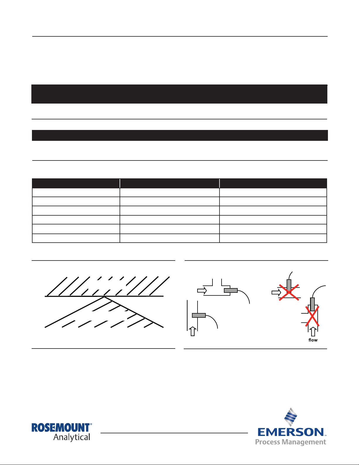
Sensor Orientation
Figure 1. Sensor Orientation
trapped air
30° 30°
°
trapped sludge
Keep ¼ in. (6 mm) clearance between electrodes and piping. The electrolytes must be completely submerged in the
process liquid, i.e., to the upper edge of the guard (item 10 in Figure 3).
°
Figure 2. Recommended Installation
flow
recommended
flow
flow
recommended
not
Page 2
402 and 402VP Instruction Manual
January 2014 LIQ_MAN_ABR_402_402VP
Installation and Retraction of Sensor
Installation
Retraction assembly kit (PN 23765-00) consists of items 1 through 7 shown in Figure 3 as well as a hex key and pipe tape.
The sensor assembly includes items 8 through 11.
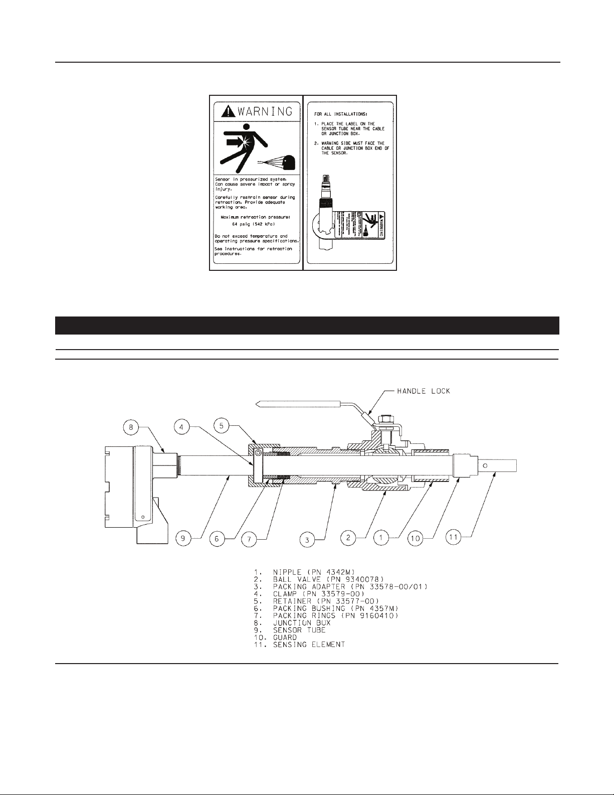
IMPORTANT!
Do not remove or alter the guard (10) on the sensor tube (9).
Figure 3. 402 Sensor with Retraction Assembly Kit
2
Page 3
Instruction Manual 402 and 402VP
LIQ_MAN_ABR_402_402VP January 2014
1. Make sure the system is shut down and there is no residual pressure.
2. Attach the ball valve (2) to the process piping using the 1–¼-inch FNPT port on the valve or the 1–¼ inch NPT nipple
(1). Use pipe tape on male threads.
3. Slide the handle lock up on the ball valve handle and close the ball valve (2). If the process will be restarted before the
sensor is installed, make sure the system pressure is at or below 542 kPa abs (64 psig) before proceeding. If the system
will not be restarted until after the sensor installation, leave the valve in the open position.
4. If the sensor includes a junction box (8), it must be removed from the sensor to install the retraction assembly kit.
Disconnect the sensor wires inside the junction box prior to disassembly.
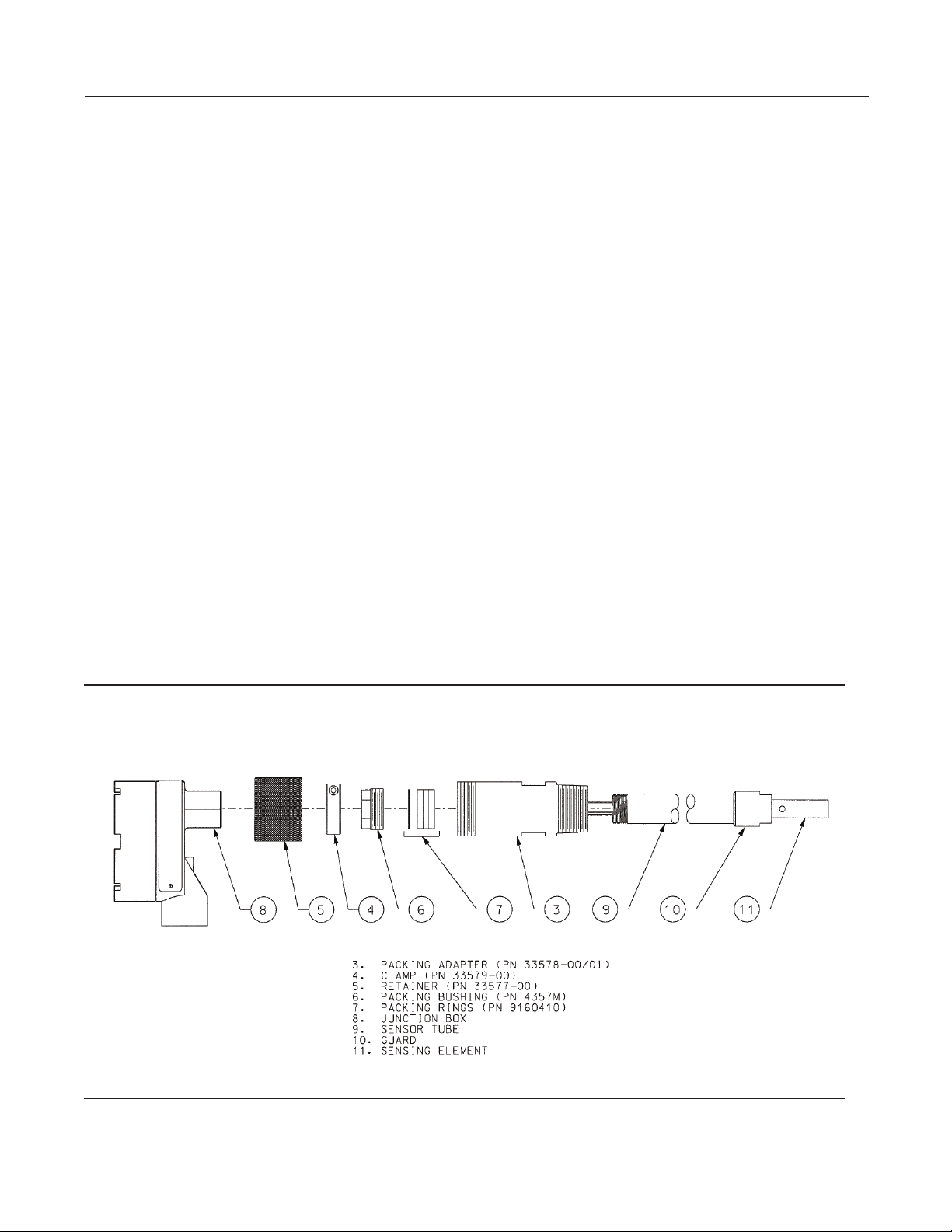
5. Follow Figure 4 to assemble the sensor and retraction assembly. Keep items 3-7 in the proper sequence. Items 3, 6, and
7 are factory assembled.
6. Position the sensor tube (9) so that the electrodes (11) are completely withdrawn inside the packing adapter (3). If it is
difcult to slide the sensor through the packing rings, loosen the packing bushing (6).
7. Position the clamp (4) on the sensor tube (9) so that the electrodes (11) will be completely immersed in the process
liquid when the sensor is fully inserted through the ball valve. See Figure 3. Use the hex key to secure the clamp to the
sensor tube.
8. Slide the retainer (5) onto the sensor tube (9).
9. Screw the junction box (8) — hand tight — onto the sensor tube (9). DO NOT OVERTIGHTEN. Use 2-3 wraps of pipe tape
on the tube threads if a NEMA 4 seal is required at the junction box.
10. Apply pipe tape to the packing adapter (3) threads and screw the packing adapter onto the ball valve.
11. Check to ensure that the packing bushing (6) has been tightened. You should be able to push the sensor tube (9)
against the resistance provided by the packing rings (7).
12. Open the ball valve (2).
13. There may be some leakage around the packing bushing (6). Tighten the packing bushing to stop the leak. Use the
junction box (8) or sensor rear to push the sensor through the valve until the clamp (4) rests against the packing
bushing.
14. To secure the sensor tube (9) in place, tighten — hand tighten only — the retainer (5) against the back of the packing
adapter (3). If the sensor tube retracts when the system pressure is increased, reduce the pressure to 542 kPa abs (64
psig) or less, remove the retainer (5), and tighten the screw in the clamp (4).
Figure 4. 402 Sensor Installation
3
Page 4

402 and 402VP Instruction Manual
January 2014 LIQ_MAN_ABR_402_402VP
Retraction
1. Make sure the system pressure is at or below 542 kPa abs (64 psig) at the valve before proceeding. Provide adequate
working area for retraction.
2. Unscrew the retainer (5) from the packing adapter (3). If it is difcult to unscrew the retainer, system pressure may be
forcing the clamp (4) into the retainer. The packing bushing (6) may not be tight enough to hold the sensor tube (9) in
place. To prevent a sudden retraction of the sensor tube as the retainer is removed, hold onto the junction box (8) or
sensor rear to restrain the sensor.
3. If the sensor tube (9) does not slide back as the retainer is unscrewed, pull back on the junction box (8) or sensor tube
to retract the sensor.
4. If the sensor tube (9) cannot be retracted, loosen the clamp (4) using the hex key. Pull the clamp back and slowly loosen
the packing bushing (6) in 1/8-turn increments. System pressure may cause the tube to retract.
If not, pull back on the junction box (8) or sensor tube (9) to withdraw the sensor.
5. Withdraw the sensor tube until the guard (10) contacts the stop inside the packing adapter (3). The electrodes (11) are
now inside the packing adapter. See Figure 5. Slide the handle lock up on the valve handle and close the ball valve (2).
IMPORTANT!
Failure to withdraw the sensor completely may result in damage to the electrodes when the valve is closed.
6. Unscrew the packing adapter (3) from the ball valve (2) to remove the sensor and retraction assembly.
Figure 5. 402 Sensor in Retracted Position
4
Page 5

Instruction Manual 402 and 402VP
LIQ_MAN_ABR_402_402VP January 2014
Wiring
Note
For additional wiring information on this product, including sensor combinations not shown here, please refer to either our online
wiring programs or the Manual DVD enclosed with each product.
1056, 1057, 56, 5081, 6081, 54e, and XMT : http://www3.emersonprocess.com/raihome/sp/liquid/wiring/XMT/
1066 and sensors with SMART preamps: http://www2.emersonprocess.com/en-US/brands/rosemountanalytical/Liquid/Sensors/
Pages/Wiring_Diagram.aspx
1055: http://www3.emersonprocess.com/raihome/sp/liquid/wiring/1055/
Wire Color and Connections in Sensor
Color Function
Gray Connects to outer electrode
Clear Coaxial shield for gray wire
Orange Connects to inner electrode
Clear Coaxial shield for orange wire
Red
White with red stripe
White
Clear Shield for all RTD lead wires
RTD
RTD in
RTD sense
RTD return
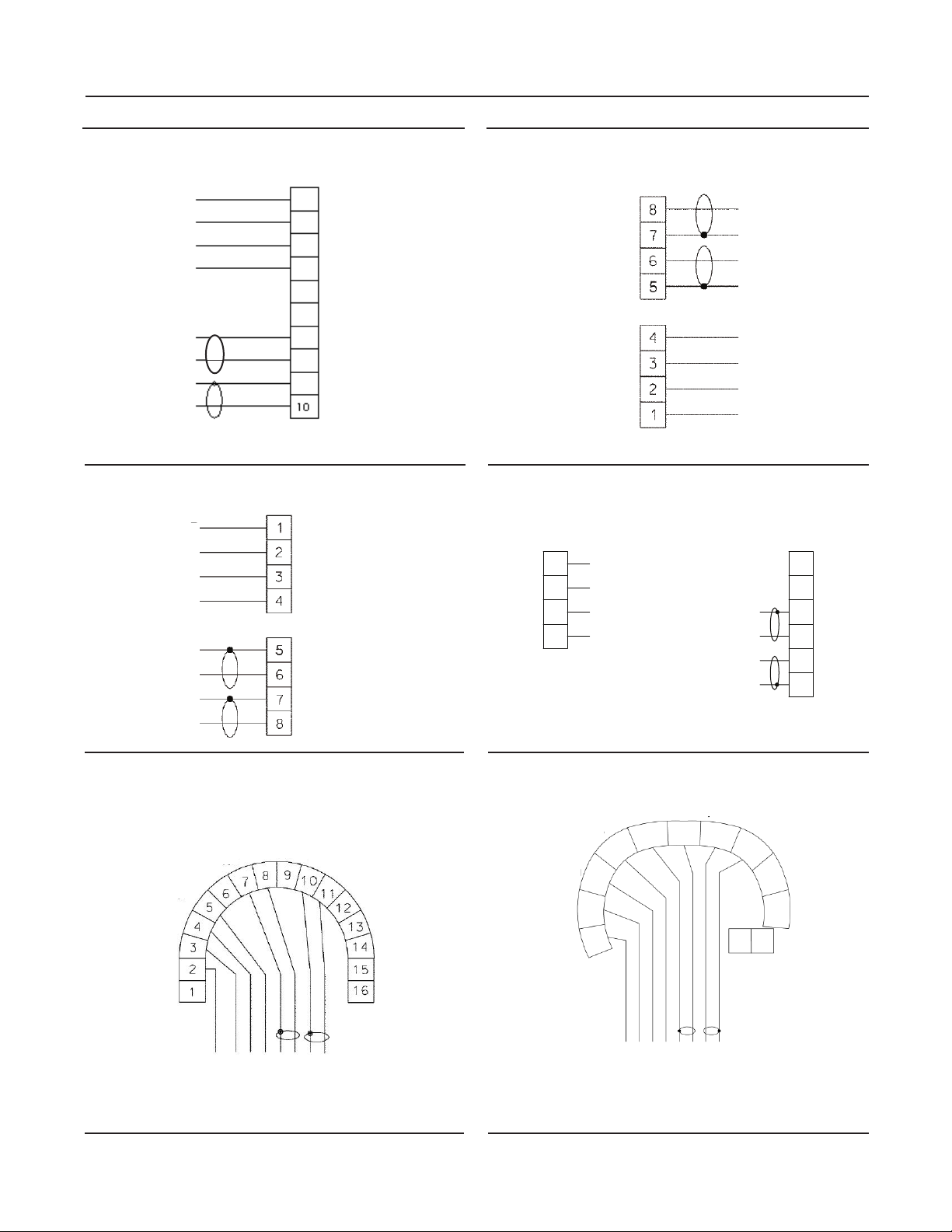
Wiring Diagrams
Figure 6. Wiring for Sensor-Mounted Junction Box Figure 7. Wiring for 54eC and 54C
MODEL 54C & 54eC
ANALYZERS
TB
CABLE
SENSOR
GRAY
GRAY
WIRES
CLEAR
RED
RED
ORANGE
RED
CLEAR
Note: Terminals in junction
box are not numbered.
WHITE
ORANGE
GROUND
RTD SHIELD
RTD RETURN
RTD SENSE
RECEIVE COMMON
CLEAR
WHT/RED
DRIVE COMMON
RECEIVE
GROUND
TB1
RTD IN
N/C
N/C
DRIVE
SENSOR CABLE
CLEAR
WHITE
WHITE/RED
RED
CLEAR
ORANGE
CLEAR
GRAY
5
Page 6
402 and 402VP Instruction Manual
RCV B
RCV A
RSHLD
DRVB
DRVA
DSHLD
LTR
REVISIONS
DESCRIPTION
DATE
APVD
B
REVISED
12-8-10
J. COVEY
January 2014 LIQ_MAN_ABR_402_402VP
Figure 8. Wiring for 56 and 1056
TB1
1
WHITE
WHITE/RED
RED
CLEAR
CLEAR
ORANGE
CLEAR
GRAY
RTD RTN
2
RTD SENSE
RTD IN
3
RTD SHLD
4
5
4CTB
4CTA
6
SHLD 2CT
7
SEN 2CTB
8
9
SHLD 2CT
10
SEN 2CTA
Figure 10. Wiring for Xmt-C-11 (Pipe or Wall)
TB1
CLEAR
WHITE
RED/WHITE
RED
CLEAR
ORANGE
CLEAR
GRAY
RTD SHIELD
RTD COM
RTD SENSE
RTD IN
RECEIVE COM
RECEIVE
DRIVE COM
DRIVE
Figure 9. Wiring (Panel) for Xmt-C-10
TB1
DRIVE
DRIVE COM
RECEIVE
RECEIVE COM
RTD IN
RTD SENSE
RTD COM
RTD SHIELD
Figure 11. Wiring for 1066
RTN
SENSE
RTD IN
SHLD
WHITE
WHITE
WHITE/RED
WHITE/RED
RED
RED
CLEAR
CLEAR
CLEAR
CLEAR
GRAY
GRAY
ORANGE
ORANGE
CLEAR
CLEAR
GRAY
CLEAR
ORANGE
CLEAR
RED
RED/WHITE
WHITE
CLEAR
TB1
TB1TB2
RCV B
RCV A
RSHLD
DRVB
DRVA
DSHLD
Figure 12. Wiring for 5081-C
MODEL 5081
TRANSMITTER
RCV
RCV
COM
RCV SHLD
RTD IN
RTD SENSE
RTD COM
RTD SHLD
RESERVED
RED
WHITE
CLEAR
WHITE/RED
6
DRV
SHLD
CLEAR
ORANGE
DRV
COM
DRV
GRAY
CLEAR
HT/FF (-)
HT/FF (+)
Figure 13. Wiring for 6081-C
SHIELD
RTD SHIELD
RTD IN
SENSE
RTD RTN
2CT-A
RED
WHITE
CLEAR
RED/WHITE
2CT-B
SMART PWR
GRAY
CLEAR
ORANGE
SHIELD
4CT-A
4CT-B
CLEAR
Page 7

Instruction Manual 402 and 402VP
LIQ_MAN_ABR_402_402VP January 2014
Wiring through a Junction Box
If wiring connections are made through a remote junction box (PN 23550-00), wire point-to-point. Use interconnecting
cable 23747-00 (factory-terminated) or 9200275 (no terminations).
Pin Out Diagram for 402VP
Figure 14. VP pin-out
Cleaning the Sensor
Use a warm detergent solution and a soft brush or pipe cleaner to remove oil and scale. Isopropyl alcohol (rubbing alcohol) can
also be used to remove oily lms. Avoid using strong mineral acids to clean conductivity sensors.
Calibration
ENDURANCE conductivity sensors are calibrated at the factory and do not need calibration when rst placed in service. Simply
enter the cell constant printed on the label into the analyzer.
After a period of service, the sensor may require calibration. The sensor can be calibrated against a solution having known
conductivity or against a referee meter and sensor. If using a standard solution, choose one having conductivity in the
recommended operating for the sensor cell constant. Refer to the analyzer manual or product data sheet for recommended
ranges. Do not use standard solutions having conductivity less than about 100 uS/cm. They are susceptible to contamination
by atmospheric carbon dioxide, which can alter the conductivity by a variable amount as great as 1.2 uS/cm (at 25 °C). Because
0.01/cm sensors must be calibrated in low conductivity solutions, they are best calibrated against a referee meter and sensor in
a closed system.
For more information about calibrating contacting conductivity sensors, refer to application sheet ADS 43-024, available
on the Rosemount Analytical website.
Troubleshooting
Problem Probable Cause Solution
Wiring is wrong. Verify wiring.
Check temperature element for open or
short circuits. See Figure 15 (next page).
Be sure sensor is completely submerged in
process stream.
Perform isolation checks.
See Figure 16 (next page).
Be sure sensor is completely submerged in
process stream.
Be sure sensor is properly oriented in
pipe or ow cell. See Figure 1. Apply back
pressure to ow cell.
Check that temperature correction is
appropriate for the sample. See analyzer
manual for more information.
Verify that the correct cell constant has
been entered in the analyzer and that
the cell constant is appropriate for the
conductivity of the sample. See analyzer
manual.
Move sensor to a location more
representative of the process liquid.
Off-scale reading
Noisy reading
Reading seems wrong (lower or higher
than expected
Sluggish response
Temperature element is open or shorted.
Sensor is not in process stream.
Variopol cable is not properly seated. Loosen connector and reseat.
Sensor has failed.
Sensor is improperly installed in process
stream.
Variopol cable is not properly seated. Loosen connector and reseat.
Bubbles trapped in sensor.
Wrong temperature correction algorithm.
Wrong cell constant.
Electrodes are fouled. Clean electrodes.
Sensor is installed in dead area in piping.
7
Page 8

402 and 402VP Instruction Manual
January 2014 LIQ_MAN_ABR_402_402VP
Rev. L
Figure 15. Checking Temperature Element
Disconnect leads and measure resistances shown. The measured resistance should be close to the value in the table.
Figure 16. Checking Continuity and Leakage
Disconnect electrode leads and measure resistance and
continuity as shown. Sensor must be dry when checking
resistance between electrode leads.
facebook.com/EmersonRosemountAnalytical
AnalyticExpert.com
twitter.com/RAIhome
youtube.com/user/RosemountAnalytical
Emerson Process Management
2400 Barranca Parkway
Irvine, CA 92606 USA
Tel: (949) 757-8500
Fax: (949) 474-7250
rosemountanalytical.com
© Rosemount Analytical Inc. 2013
8
Credit Cards for U.S. Purchases Only.
©2014 Rosemount Analytical, Inc. All rights reserved.
The Emerson logo is a trademark and service mark of Emerson Electric Co. Brand name is a mark of one
of the Emerson Process Management family of companies. All other marks are the property of their
respective owners.
The contents of this publication are presented for information purposes only, and while effort has been
made to ensure their accuracy, they are not to be construed as warranties or guarantees, express or
implied, regarding the products or services described herein or their use or applicability. All sales are
governed by our terms and conditions, which are available on request. We reserve the right to modify
or improve the designs or specications of our products at any time without notice.
 Loading...