

Page 1
MON 20/20
Software for Gas Chromatographs
Revision D
3-9000-745
October 2010
Applies to all Emerson XA Series Gas Chromatographs
Page 2
MON 20/20 Software for Gas Chromatographs
User Manual
NOTICE
DANIEL MEASUREMENT AND CONTROL, INC. AND ROSEMOUNT ANALYTICAL
(COLLECTIVELY, “SELLER”) SHALL NOT BE LIABLE FOR TECHNICAL OR EDITORIAL
ERRORS IN THIS MANUAL OR OMISSIONS FROM THIS MANUAL. SELLER MAKES NO
WARRANTIES, EXPRESSED OR IMPLIED, INCLUDING THE IMPLIED WARRANTIES OF
MERCHANTABILITY AND FITNESS FOR A PARTICULAR PURPOSE WITH RESPECT TO
THIS MANUAL AND, IN NO EVENT, SHALL SELLER BE LIABLE FOR ANY SPECIAL OR
CONSEQUENTIAL DAMAGES INCLUDING, BUT NOT LIMITED TO, LOSS OF
PRODUCTION, LOSS OF PROFITS, ETC.
PRODUCT NAMES USED HEREIN ARE FOR MANUFACTURER OR SUPPLIER
IDENTIFICATION ONLY AND MAY BE TRADEMARKS/REGISTERED TRADEMARKS OF
THESE COMPANIES.
THE CONTENTS OF THIS PUBLICATION ARE PRESENTED FOR INFORMATIONAL
PURPOSES ONLY, AND WHILE EVERY EFFORT HAS BEEN MADE TO ENSURE THEIR
ACCURACY, THEY ARE NOT TO BE CONSTRUED AS WARRANTIES OR GUARANTEES,
EXPRESSED OR IMPLIED, REGARDING THE PRODUCTS OR SERVICES DESCRIBED
HEREIN OR THEIR USE OR APPLICABILITY. WE RESERVE THE RIGHT TO MODIFY OR
IMPROVE THE DESIGNS OR SPECIFICATIONS OF SUCH PRODUCTS AT ANY TIME.
SELLER DOES NOT ASSUME RESPONSIBILITY FOR THE SELECTION, USE OR
MAINTENANCE OF ANY PRODUCT. RESPONSIBILITY FOR PROPER SELECTION, USE
AND MAINTENANCE OF ANY SELLER PRODUCT REMAINS SOLELY WITH THE
PURCHASER AND END-USER.
DANIEL AND THE DANIEL LOGO ARE REGISTERED TRADEMARKS OF DANIEL
MEASUREMENT AND CONTROL, INC. ROSEMOUNT AND THE ROSEMOUNT
ANALYTICAL LOGO ARE REGISTERED TRADEMARKS OF ROSEMOUNT ANALYTICAL.
THE EMERSON LOGO IS A TRADEMARK AND SERVICE MARK OF EMERSON ELECTRIC
CO.
COPYRIGHT
All rights reserved. No part of this work may be reproduced or copied in any form or by any
means - graphic, electronic, or mechanical — without first receiving the written permission of
©
2010 BY DANIEL MEASUREMENT AND CONTROL, INC., HOUSTON,
TEXAS, U.S.A.
Daniel Measurement and Control, Inc. Houston, Texas, U.S.A.
Page 3

WARRANTY
1. LIMITED WARRANTY: Subject to the limitations contained in Section 2 herein and except as
otherwise expressly provided herein, Daniel Measurement and Control, Inc. and Rosemount
Analytical, (collectively“Seller”) warrants that the firmware will execute the programming
instructions provided by Seller, and that the Goods manufactured or Services provided by Seller
will be free from defects in materials or workmanship under normal use and care until the
expiration of the applicable warranty period. Goods are warranted for twelve (12) months from
the date of initial installation or eighteen (18) months from the date of shipment by Seller,
whichever period expires first. Consumables and Services are warranted for a period of 90 days
from the date of shipment or completion of the Services. Products purchased by Seller from a third
party for resale to Buyer ("Resale Products") shall carry only the warranty extended by the
original manufacturer. Buyer agrees that Seller has no liability for Resale Products beyond
making a reasonable commercial effort to arrange for procurement and shipping of the Resale
Products. If Buyer discovers any warranty defects and notifies Seller thereof in writing during the
applicable warranty period, Seller shall, at its option, promptly correct any errors that are found
by Seller in the firmware or Services, or repair or replace F.O.B. point of manufacture that
portion of the Goods or firmware found by Seller to be defective, or refund the purchase price of
the defective portion of the Goods/Services. All replacements or repairs necessitated by
inadequate maintenance, normal wear and usage, unsuitable power sources, unsuitable
environmental conditions, accident, misuse, improper installation, modification, repair, storage or
handling, or any other cause not the fault of Seller are not covered by this limited warranty, and
shall be at Buyer's expense. Seller shall not be obligated to pay any costs or charges incurred by
Buyer or any other party except as may be agreed upon in writing in advance by an authorized
Seller representative. All costs of dismantling, reinstallation and freight and the time and
expenses of Seller's personnel for site travel and diagnosis under this warranty clause shall be
borne by Buyer unless accepted in writing by Seller. Goods repaired and parts replaced during the
warranty period shall be in warranty for the remainder of the original warranty period or ninety
(90) days, whichever is longer. This limited warranty is the only warranty made by Seller and
can be amended only in a writing signed by an authorized representative of Seller. Except as
otherwise expressly provided in the Agreement, THERE ARE NO REPRESENTATIONS OR
WARRANTIES OF ANY KIND, EXPRESSED OR IMPLIED, AS TO MERCHANTABILITY,
FITNESS FOR PARTICULAR PURPOSE, OR ANY OTHER MATTER WITH RESPECT TO ANY
OF THE GOODS OR SERVICES. It is understood that corrosion or erosion of materials is
not covered by our guarantee.
2.
LIMITATION OF REMEDY AND LIABILITY: SELLER SHALL NOT BE LIABLE FOR
DAMAGES CAUSED BY DELAY IN PERFORMANCE. THE SOLE AND EXCLUSIVE REMEDY
FOR BREACH OF WARRANTY HEREUNDER SHALL BE LIMITED TO REPAIR,
CORRECTION, REPLACEMENT OR REFUND OF PURCHASE PRICE UNDER THE LIMITED
WARRANTY CLAUSE IN SECTION 1 HEREIN. IN NO EVENT, REGARDLESS OF THE FORM
OF THE CLAIM OR CAUSE OF ACTION (WHETHER BASED IN CONTRACT,
INFRINGEMENT, NEGLIGENCE, STRICT LIABILITY, OTHER TORT OR OTHERWISE),
SHALL SELLER'S LIABILITY TO BUYER AND/OR ITS CUSTOMERS EXCEED THE PRICE
TO BUYER OF THE SPECIFIC GOODS MANUFACTURED OR SERVICES PROVIDED BY
SELLER GIVING RISE TO THE CLAIM OR CAUSE OF ACTION. BUYER AGREES THAT IN
NO EVENT SHALL SELLER'S LIABILITY TO BUYER AND/OR ITS CUSTOMERS EXTEND
TO INCLUDE INCIDENTAL, CONSEQUENTIAL OR PUNITIVE DAMAGES. THE TERM
"CONSEQUENTIAL DAMAGES" SHALL INCLUDE, BUT NOT BE LIMITED TO, LOSS OF
ANTICIPATED PROFITS, LOSS OF USE, LOSS OF REVENUE AND COST OF CAPITAL.
Page 4

IMPORTANT INSTRUCTIONS
• Read all instructions prior to installing, operating, and servicing this product.
• Follow all warnings, cautions, and instructions marked on and supplied with this product.
• Inspect the equipment packing case and if damage exists, notify your local carrier for
liability.
• Open the packing list and carefully remove equipment and spare or replacement parts
from the case. Inspect all equipment for damage and missing parts.
• If items are damaged or missing, contact the manufacturer at 1 (713) 827-6314 for
instructions about receiving replacement parts.
• Install equipment as specified per the installation instructions and per applicable local
and national codes. All connections shall be made to proper electrical and pressure
sources.
• Ensure that all equipment doors are closed and protective covers are in place, except
when maintenance is being performed by qualified persons, to prevent personal injury.
• Use of this product for any purpose other than its intended purpose may result in
property damage and/or serious injury or death.
• Before opening the flameproof enclosure in a flammable atmosphere, the electrical
circuits must be interrupted.
• Repairs must be performed using only authorized replacement parts as specified by the
manufacturer. Use of unauthorized parts can affect the product's performance and place
the safe operation of the product at risk.
• When installing or servicing ATEX-certified units, the ATEX approval applies only to
equipment without cable glands. When mounting the flameproof enclosures in a
hazardous area, only flameproof cable glands certified to IEC 60079-1 must be used.
• Technical assistance is available 24 hours a day, 7 days a week
6314.
by calling 1 (713) 827-
Page 5

This page is intentionally left blank.
Page 6

Table of Contents
Section 1:
Getting started
What’s new in MON 20/20 . . . . . . . . . . . . . . . . . . . . . . . . . . . . . .1-3
Getting started with MON 20/20 . . . . . . . . . . . . . . . . . . . . . . . . .1-6
System requirements . . . . . . . . . . . . . . . . . . . . . . . . . . . .1-6
Installing MON 20/20 . . . . . . . . . . . . . . . . . . . . . . . . . . .1-7
Launching MON 20/20 . . . . . . . . . . . . . . . . . . . . . . . . . .1-7
Registering MON 20/20 . . . . . . . . . . . . . . . . . . . . . . . . . .1-7
Setting up the data folder . . . . . . . . . . . . . . . . . . . . . . . .1-9
Configuring MON 20/20 to connect to a gas
chromatograph . . . . . . . . . . . . . . . . . . . . . . . . . . . . . . . .1-10
Importing or exporting the GC directory table . . . . . .1-13
Launching MON 20/20 from the SNAP-ON for
DeltaV . . . . . . . . . . . . . . . . . . . . . . . . . . . . . . . . . . . . . . .1-15
Launching MON 20/20 from the AMS Device
Manager . . . . . . . . . . . . . . . . . . . . . . . . . . . . . . . . . . . . .1-17
The MON 20/20 user interface . . . . . . . . . . . . . . . . . . .1-20
Connecting to a gas chromatograph . . . . . . . . . . . . . . .1-25
Disconnecting from a gas chromatograph . . . . . . . . . .1-28
Keyboard commands . . . . . . . . . . . . . . . . . . . . . . . . . . . . . . . . . .1-28
Procedures guide . . . . . . . . . . . . . . . . . . . . . . . . . . . . . . . . . . . . .1-30
Configuring a gas chromatograph . . . . . . . . . . . . . . . . . . . . . . .1-33
Editing a configuration file . . . . . . . . . . . . . . . . . . . . . .1-33
Saving a gas chromatograph’s current
configuration . . . . . . . . . . . . . . . . . . . . . . . . . . . . . . . . .1-35
Importing a configuration file . . . . . . . . . . . . . . . . . . . .1-35
Configuring your printer . . . . . . . . . . . . . . . . . . . . . . . . . . . . . .1-36
Using online help . . . . . . . . . . . . . . . . . . . . . . . . . . . . . . . . . . . .1-37
Operating modes for MON 20/20 . . . . . . . . . . . . . . . . . . . . . . . .1-37
Viewing the Physical Name column . . . . . . . . . . . . . . . . . . . . .1-37
Selecting the GC’s networking protocol . . . . . . . . . . . . . . . . . . .1-39
Using the context-sensitive variable selector . . . . . . . . . . . . . .1-41
Section 2:
Using the
chromatograph
functions
Viewing chromatograms . . . . . . . . . . . . . . . . . . . . . . . . . . . . . . . .2-1
Data displayed in the chromatogram window . . . . . . . .2-2
Viewing a live chromatogram . . . . . . . . . . . . . . . . . . . . .2-3
Viewing an archived chromatogram . . . . . . . . . . . . . . . .2-5
Protecting or unprotecting an archived
chromatogram . . . . . . . . . . . . . . . . . . . . . . . . . . . . . . . . .2-9
Viewing a saved chromatogram . . . . . . . . . . . . . . . . . .2-13
Working with the graph . . . . . . . . . . . . . . . . . . . . . . . . . . . . . . .2-15
Editing the display properties of the chromatograph . . . . . . . .2-16
The Graph bar . . . . . . . . . . . . . . . . . . . . . . . . . . . . . . . .2-16
Additional plot commands . . . . . . . . . . . . . . . . . . . . . . .2-19
i
Page 7

User Manual MON20/20 Software for Gas Chromatographs
3-9000-745 OCTOBER 2010
Working with a chromatogram . . . . . . . . . . . . . . . . . . . . . . . . . 2-21
Editing a chromatogram trace . . . . . . . . . . . . . . . . . . . 2-21
Viewing chromatogram results . . . . . . . . . . . . . . . . . . 2-23
Saving a chromatogram trace . . . . . . . . . . . . . . . . . . . 2-25
Removing a chromatogram trace from view . . . . . . . . 2-26
Forcing a calibration . . . . . . . . . . . . . . . . . . . . . . . . . . 2-27
Controlling the display of data in the Timed Events
and Components tables . . . . . . . . . . . . . . . . . . . . . . . . 2-28
Saving a comparison file . . . . . . . . . . . . . . . . . . . . . . . 2-30
Opening a comparison file . . . . . . . . . . . . . . . . . . . . . . 2-30
Miscellaneous commands . . . . . . . . . . . . . . . . . . . . . . . . . . . . . 2-31
Working with the Timed Events table . . . . . . . . . . . . 2-32
Editing Timed Events from the Time Events
window . . . . . . . . . . . . . . . . . . . . . . . . . . . . . . . . . . . . . 2-33
Editing Timed Events from the Chromatogram
Viewer . . . . . . . . . . . . . . . . . . . . . . . . . . . . . . . . . . . . . . 2-33
Using the Chromatogram Viewer’s cursor to
update a Timed Event . . . . . . . . . . . . . . . . . . . . . . . . . 2-35
Working with the Component Data Table . . . . . . . . . 2-37
Editing retention times from the Chromatogram
Viewer . . . . . . . . . . . . . . . . . . . . . . . . . . . . . . . . . . . . . . 2-38
Viewing raw data . . . . . . . . . . . . . . . . . . . . . . . . . . . . . 2-38
Setting the gas chromatograph’s date and time . . . . . . . . . . . 2-40
Adjusting daylight savings . . . . . . . . . . . . . . . . . . . . . 2-42
Section 3:
Using the hardware
functions
Controlling the temperature of the gas chromatograph’s
heaters . . . . . . . . . . . . . . . . . . . . . . . . . . . . . . . . . . . . . . . . . . . . . 3-1
Renaming a heater . . . . . . . . . . . . . . . . . . . . . . . . . . . . . 3-2
Setting the heater’s type . . . . . . . . . . . . . . . . . . . . . . . . 3-3
Monitoring the temperature of a heater . . . . . . . . . . . . 3-4
Monitoring the operational status of a heater . . . . . . . 3-5
Setting the desired temperature . . . . . . . . . . . . . . . . . . 3-6
Setting PWM Output . . . . . . . . . . . . . . . . . . . . . . . . . . . 3-7
Removing a heater from service . . . . . . . . . . . . . . . . . . 3-9
Configuring the valves . . . . . . . . . . . . . . . . . . . . . . . . . . . . . . . 3-10
Renaming a valve . . . . . . . . . . . . . . . . . . . . . . . . . . . . . 3-10
Setting a valve’s operational mode . . . . . . . . . . . . . . . 3-12
Monitoring the operational status of a valve . . . . . . . 3-13
Inverting the polarity of a valve . . . . . . . . . . . . . . . . . 3-14
Setting the usage mode for a valve . . . . . . . . . . . . . . . 3-15
Controlling the detectors . . . . . . . . . . . . . . . . . . . . . . . . . . . . . 3-17
Offsetting the baseline . . . . . . . . . . . . . . . . . . . . . . . . . 3-19
Igniting the FID flame . . . . . . . . . . . . . . . . . . . . . . . . . 3-21
Resetting the preamp value . . . . . . . . . . . . . . . . . . . . . 3-22
Balancing the preamp . . . . . . . . . . . . . . . . . . . . . . . . . 3-22
ii
Page 8

MON20/20 Software for Gas Chromatographs User Manual
OCTOBER 2010 3-9000-745
Managing your gas chromatograph’s discrete inputs . . . . . . . .3-24
Renaming a discrete input . . . . . . . . . . . . . . . . . . . . . .3-24
Setting a discrete input’s operational mode . . . . . . . . .3-25
Monitoring the operational status of a discrete
input . . . . . . . . . . . . . . . . . . . . . . . . . . . . . . . . . . . . . . . .3-27
Inverting the polarity of a discrete input . . . . . . . . . . .3-28
Managing your gas chromatograph’s discrete outputs . . . . . . .3-29
Renaming a discrete output . . . . . . . . . . . . . . . . . . . . .3-29
Setting a discrete output’s operational mode . . . . . . . .3-30
Monitoring the operational status of a discrete
output . . . . . . . . . . . . . . . . . . . . . . . . . . . . . . . . . . . . . . .3-32
Setting the usage mode for a discrete output . . . . . . . .3-33
Managing your gas chromatograph’s analog inputs . . . . . . . . .3-34
Renaming an analog input . . . . . . . . . . . . . . . . . . . . . .3-35
Setting a analog input’s operational mode . . . . . . . . . .3-36
Setting the scale values for an analog input
device . . . . . . . . . . . . . . . . . . . . . . . . . . . . . . . . . . . . . . .3-37
Setting the type of analog input signal . . . . . . . . . . . .3-37
Monitoring the status of an analog input . . . . . . . . . . .3-39
Calibrating an analog input . . . . . . . . . . . . . . . . . . . . .3-40
Managing your gas chromatograph’s analog outputs . . . . . . . .3-43
Renaming an analog output . . . . . . . . . . . . . . . . . . . . .3-43
Setting a analog output’s operational mode . . . . . . . . .3-44
Setting the scale values for an analog output
device . . . . . . . . . . . . . . . . . . . . . . . . . . . . . . . . . . . . . . .3-45
Mapping a system variable to an analog output . . . . .3-46
Monitoring the status of an analog output . . . . . . . . . .3-47
Calibrating an analog output . . . . . . . . . . . . . . . . . . . .3-48
Reviewing the Hardware Inventory List . . . . . . . . . . . . . . . . . .3-52
Section 4:
Using the
Application
functions
Managing the system . . . . . . . . . . . . . . . . . . . . . . . . . . . . . . . . . .4-2
Managing Component Data Tables . . . . . . . . . . . . . . . . . . . . . . .4-5
Editing a Component Data Table . . . . . . . . . . . . . . . . . .4-6
Adding a component to a Component Data
Table . . . . . . . . . . . . . . . . . . . . . . . . . . . . . . . . . . . . . . . .4-10
Removing a component from a Component
Data Table . . . . . . . . . . . . . . . . . . . . . . . . . . . . . . . . . . .4-12
Viewing the standard values for a component . . . . . . .4-13
Viewing raw data . . . . . . . . . . . . . . . . . . . . . . . . . . . . . .4-15
Managing timed events . . . . . . . . . . . . . . . . . . . . . . . . . . . . . . .4-17
Editing valve events . . . . . . . . . . . . . . . . . . . . . . . . . . .4-20
Editing integration events . . . . . . . . . . . . . . . . . . . . . .4-22
Editing spectrum gain events . . . . . . . . . . . . . . . . . . . .4-26
Setting the cycle and analysis time . . . . . . . . . . . . . . .4-29
Removing an event from the Timed Event
Table . . . . . . . . . . . . . . . . . . . . . . . . . . . . . . . . . . . . . . . .4-31
Adding an event to the Timed Event Table . . . . . . . . .4-33
iii
Page 9

User Manual MON20/20 Software for Gas Chromatographs
3-9000-745 OCTOBER 2010
Managing Validation Data Tables . . . . . . . . . . . . . . . . . . . . . . 4-35
Managing calculations . . . . . . . . . . . . . . . . . . . . . . . . . . . . . . . 4-37
Setting standard calculations by stream . . . . . . . . . . 4-37
Editing average calculations . . . . . . . . . . . . . . . . . . . . 4-39
Viewing an archive of averages for a given variable . 4-42
Copying stream settings . . . . . . . . . . . . . . . . . . . . . . . 4-44
Copying component settings . . . . . . . . . . . . . . . . . . . . 4-45
Creating Custom Calculations . . . . . . . . . . . . . . . . . . . . . . . . . 4-47
Inserting a Comment . . . . . . . . . . . . . . . . . . . . . . . . . . 4-54
Inserting a Conditional Statement . . . . . . . . . . . . . . . 4-56
Inserting an Expression . . . . . . . . . . . . . . . . . . . . . . . . 4-59
Creating a Constant . . . . . . . . . . . . . . . . . . . . . . . . . . . 4-61
Creating or Editing a Temporary Variable . . . . . . . . . 4-63
Inserting a System Variable . . . . . . . . . . . . . . . . . . . . 4-64
Using User-defined Calculations . . . . . . . . . . . . . . . . . 4-65
Setting the calculation method . . . . . . . . . . . . . . . . . . . . . . . . . 4-67
Setting alarm limits . . . . . . . . . . . . . . . . . . . . . . . . . . . . . . . . . 4-69
Managing system alarms . . . . . . . . . . . . . . . . . . . . . . . . . . . . . 4-72
Managing streams . . . . . . . . . . . . . . . . . . . . . . . . . . . . . . . . . . . 4-74
Designating how a stream will be used . . . . . . . . . . . 4-74
Assigning a valve to a stream and setting the
relationship between the stream’s open state to
the valve’s On/Off state . . . . . . . . . . . . . . . . . . . . . . . . 4-76
Assigning a data table to a particular stream . . . . . . 4-77
Changing the base pressure for a stream . . . . . . . . . . 4-78
Creating a stream sequence for a detector . . . . . . . . . . . . . . . 4-78
Communications . . . . . . . . . . . . . . . . . . . . . . . . . . . . . . . . . . . . 4-80
Creating or editing registers . . . . . . . . . . . . . . . . . . . . 4-81
Creating a new map file . . . . . . . . . . . . . . . . . . . . . . . . 4-86
Assigning a variable to a register . . . . . . . . . . . . . . . . 4-92
Viewing or editing scales . . . . . . . . . . . . . . . . . . . . . . . 4-92
Configuring the gas chromatograph’s Ethernet port . . . . . . . 4-95
Working with local operator interface variables . . . . . . . . . . . 4-96
Mapping Foundation Fieldbus variables . . . . . . . . . . . . . . . . . 4-98
Section 5:
Logs and reports
iv
Viewing and clearing alarms . . . . . . . . . . . . . . . . . . . . . . . . . . . 5-1
Viewing unacknowledged and active alarms . . . . . . . . 5-2
Acknowledging and clearing alarms . . . . . . . . . . . . . . . 5-3
Viewing the alarm log . . . . . . . . . . . . . . . . . . . . . . . . . . 5-4
Viewing the maintenance log . . . . . . . . . . . . . . . . . . . . . . . . . . . 5-7
Adding an Entry to the Maintenance Log . . . . . . . . . . 5-8
Deleting an entry from the maintenance log . . . . . . . . 5-9
Working with the parameter list . . . . . . . . . . . . . . . . . . . . . . . 5-10
Viewing and editing the parameter list . . . . . . . . . . . 5-10
Importing and exporting the parameter list . . . . . . . . 5-12
Working with drawings and documents . . . . . . . . . . . . . . . . . 5-13
Viewing drawings or documents . . . . . . . . . . . . . . . . . 5-15
Page 10

MON20/20 Software for Gas Chromatographs User Manual
OCTOBER 2010 3-9000-745
Adding files to the GC . . . . . . . . . . . . . . . . . . . . . . . . . .5-17
Deleting files from the GC . . . . . . . . . . . . . . . . . . . . . . .5-18
Viewing the event log . . . . . . . . . . . . . . . . . . . . . . . . . . . . . . . . .5-19
Displaying reports . . . . . . . . . . . . . . . . . . . . . . . . . . . . . . . . . . .5-22
Understanding report types . . . . . . . . . . . . . . . . . . . . .5-22
Viewing reports from live data . . . . . . . . . . . . . . . . . . .5-32
Viewing a saved report . . . . . . . . . . . . . . . . . . . . . . . . .5-35
Viewing reports based on archived data . . . . . . . . . . . . . . . . . .5-37
Viewing analysis and calibration reports based
on archived data . . . . . . . . . . . . . . . . . . . . . . . . . . . . . . .5-37
Viewing average reports based on archived data . . . .5-41
Printing reports automatically . . . . . . . . . . . . . . . . . . .5-44
Viewing trend data . . . . . . . . . . . . . . . . . . . . . . . . . . . . . . . . . . .5-46
Viewing live trend data . . . . . . . . . . . . . . . . . . . . . . . . .5-46
Viewing saved trend data . . . . . . . . . . . . . . . . . . . . . . .5-50
Working with the Trend Graph . . . . . . . . . . . . . . . . . . . . . . . . .5-52
Editing the display properties of the graph . . . . . . . . . . . . . . .5-54
The graph bar . . . . . . . . . . . . . . . . . . . . . . . . . . . . . . . . .5-54
Working with a trend graph . . . . . . . . . . . . . . . . . . . . . . . . . . . .5-58
Editing a trend graph . . . . . . . . . . . . . . . . . . . . . . . . . .5-59
Entering a description for a trend graph . . . . . . . . . . .5-60
Saving a trend trace . . . . . . . . . . . . . . . . . . . . . . . . . . .5-61
Removing a trend graph from view . . . . . . . . . . . . . . .5-62
Displaying trend data . . . . . . . . . . . . . . . . . . . . . . . . . .5-62
Generating a GC Configuration Report . . . . . . . . . . . . . . . . . . .5-65
Deleting archived data from the gas chromatograph . . . . . . . .5-88
The molecular weight vs. response factor graph . . . . . . . . . . . .5-89
Section 6:
Controlling
Analyses
Section 7:
Using MON 20/20
Tools
Halting an analysis . . . . . . . . . . . . . . . . . . . . . . . . . . . . . . . . . . . .6-1
Auto sequencing . . . . . . . . . . . . . . . . . . . . . . . . . . . . . . . . . . . . . .6-2
Analyzing a single stream . . . . . . . . . . . . . . . . . . . . . . . . . . . . . .6-4
Calibrating the gas chromatograph . . . . . . . . . . . . . . . . . . . . . . .6-5
Validating the Gas Chromatograph . . . . . . . . . . . . . . . . . . . . . .6-7
Stopping an Analysis Run . . . . . . . . . . . . . . . . . . . . . . . . . . . . . .6-9
Using the Modbus Test program . . . . . . . . . . . . . . . . . . . . . . . . .7-1
Comparing Modbus protocols . . . . . . . . . . . . . . . . . . . . .7-2
Setting communication parameters . . . . . . . . . . . . . . . .7-3
Getting Modbus Data . . . . . . . . . . . . . . . . . . . . . . . . . . .7-5
Transmitting using a single data type . . . . . . . . . . . . . .7-7
Transmitting using a template . . . . . . . . . . . . . . . . . . .7-10
Setting the log parameters . . . . . . . . . . . . . . . . . . . . . .7-13
Saving Modbus data . . . . . . . . . . . . . . . . . . . . . . . . . . .7-15
Printing Modbus data . . . . . . . . . . . . . . . . . . . . . . . . . .7-15
Assigning scale ranges to User_Modbus registers . . . .7-15
Troubleshooting communication errors . . . . . . . . . . . . . . . . . . .7-15
v
Page 11

User Manual MON20/20 Software for Gas Chromatographs
3-9000-745 OCTOBER 2010
Managing users . . . . . . . . . . . . . . . . . . . . . . . . . . . . . . . . . . . . . 7-17
Creating users . . . . . . . . . . . . . . . . . . . . . . . . . . . . . . . 7-20
Exporting a list of user profiles . . . . . . . . . . . . . . . . . . 7-21
Importing a list of user profiles . . . . . . . . . . . . . . . . . . 7-23
Editing users . . . . . . . . . . . . . . . . . . . . . . . . . . . . . . . . 7-26
Removing a user . . . . . . . . . . . . . . . . . . . . . . . . . . . . . . 7-27
Changing a user’s password . . . . . . . . . . . . . . . . . . . . 7-28
Finding out who is connected to the gas
chromatograph . . . . . . . . . . . . . . . . . . . . . . . . . . . . . . . 7-30
Upgrading the firmware . . . . . . . . . . . . . . . . . . . . . . . . . . . . . . 7-30
Cold booting . . . . . . . . . . . . . . . . . . . . . . . . . . . . . . . . . . . . . . . . 7-33
Viewing diagnostics . . . . . . . . . . . . . . . . . . . . . . . . . . . . . . . . . . 7-33
Adjusting the sensitivity of the LOI Keys . . . . . . . . . . . . . . . . 7-35
Setting the ROC card type . . . . . . . . . . . . . . . . . . . . . . . . . . . . 7-36
Appendix A: Component Data Table
Appendix B:
Data computations
Appendix C:
Modbus registers list for
2350A GC
Appendix D:
Basic and advanced
system variables
Appendix E:
Creating custom
calculations
Data acquisition . . . . . . . . . . . . . . . . . . . . . . . . . . . . . . . . . . . . . B-1
Peak detection . . . . . . . . . . . . . . . . . . . . . . . . . . . . . . . . . . . . . . . B-2
Analysis computations . . . . . . . . . . . . . . . . . . . . . . . . . . . . . . . . B-3
Concentration analysis with response factor . . . . . . . . B-4
Post analysis computations . . . . . . . . . . . . . . . . . . . . . . . . . . . . B-6
Liquid equivalent computations . . . . . . . . . . . . . . . . . . B-6
Heating value calculations . . . . . . . . . . . . . . . . . . . . . . B-7
Multi-level calibration . . . . . . . . . . . . . . . . . . . . . . . . . B-13
Indirect calibration . . . . . . . . . . . . . . . . . . . . . . . . . . . B-14
User_Modbus register list . . . . . . . . . . . . . . . . . . . . . . . . . . . . . . C-1
SIM_2251 Modbus register list . . . . . . . . . . . . . . . . . . . . . . . . . C-7
GPA system variables . . . . . . . . . . . . . . . . . . . . . . . . . . . . . . . . . D-1
ISO system variables . . . . . . . . . . . . . . . . . . . . . . . . . . . . . . . . D-10
Inserting a comment . . . . . . . . . . . . . . . . . . . . . . . . . . . . . . . . . . E-7
Inserting a conditional statement . . . . . . . . . . . . . . . . . . . . . . . E-9
Inserting an expression . . . . . . . . . . . . . . . . . . . . . . . . . . . . . . . E-11
Creating a constant . . . . . . . . . . . . . . . . . . . . . . . . . . . . . . . . . . E-14
Creating or editing a temporary variable . . . . . . . . . . . . . . . . E-15
Inserting a system variable . . . . . . . . . . . . . . . . . . . . . . . . . . . E-16
Using user-defined calculations . . . . . . . . . . . . . . . . . . . . . . . . E-17
vi
Page 12

Section 1: Getting started
Welcome to MON 20/20—a menu-driven, Windows-based software
program designed to remotely operate and monitor the Daniel®
Danalyzer™ XA series and the Rosemount® Analytical XA series of gas
chromatographs.
MON 20/20 operates on an IBM-compatible personal computer (PC)
running the Windows XP operating system or later.
MON 20/20 can initiate or control the following gas chromatograph (GC)
functions:
• Alarm parameters
• Alarm and event processing
• Analog scale adjustments
•Analyses
• Baseline runs
• Calculation assignments and configurations
• Calibrations
• Component assignments and configurations
•Diagnostics
• Event sequences
•Halt operations
• Stream assignments and sequences
• Valve activations
• Timing adjustments
1-1
Page 13

User Manual MON20/20 Software for Gas Chromatographs
3-9000-745 OCTOBER 2010
MON 20/20 can generate the following reports:
• 24-Hour Averages
•Analysis (GPA)
• Analysis (ISO)
• Calibration
• Final Calibration
• Validation
• Final Validation
• Hourly Averages
• Monthly Averages
• GC Configuration
•Raw Data
• Variable Averages
• Weekly Averages
• Dew Temperature Calculation (optional)
MON 20/20 can access and display the following GC-generated logs:
•Alarm Log
•Event Log
• Parameter List
• Maintenance Log
1-2
Page 14

MON20/20 Software for Gas Chromatographs User Manual
OCTOBER 2010 3-9000-745
1.1 What’s new in MON 20/20
Users familiar with MON2000 or MON2000 Plus will find a few changes
when using MON 20/20:
• Login security is at the gas chromatograph level instead of at the
software level. This means that you no longer have to log in after
starting MON 20/20—but you do have to log in to the gas
chromatograph to which you are trying to connect. For more
information, see “Connecting to a gas chromatograph” on page 1-25.
• An “administrator” role has been added to the list of user roles. This
new role has the highest level of authority and is the only role that can
create or delete all other roles. For more information, see “Managing
users” on page 7-17.
• Multiple users can connect to the same gas chromatograph simultaneously. By default, the first user to log in to the GC with “supervisor”
authority will have read/write access; all other users, including other
supervisor-level users, will have read access only. This configuration
can be changed so that all supervisor-level users have read/write
access regardless of who logs in first. For more information, see
“Managing the system” on page 4-2.
• Users can display multiple windows within MON 20/20.
• Automatic reconnection. If MON 20/20 loses its connection with the
GC, it automatically attempts to reconnect.
• Users can view multiple instances of certain windows. To aid in data
processing or troubleshooting, MON 20/20 is capable of displaying
more than one instance of certain data-heavy windows such as the
Chromatogram Viewer and the Trend Data window.
1-3
Page 15

User Manual MON20/20 Software for Gas Chromatographs
3-9000-745 OCTOBER 2010
• Enhanced Chromatogram Viewer. The following enhancements have
been made to the Chromatogram Viwer:
- Users can view an unlimited number of chromatograms, in any
configuration. For example, a user can view an archived
chromatogram and a live chromatogram. For more information,
see “Viewing chromatograms” on page 2-1.
- The “Keep Last CGM” option. Upon starting a new run, MON 20/
20 can keep the most recently completed chromatogram on the
graph for reference.
- Overview window
. When zoomed in to a smaller section of a
chromatogram, the user can open a miniature ‘overview’ window
that displays the entire chromatogram, for reference. For more
information, see “Additional plot commands” on page 2-19.
- Older chromatograms available
. MON 20/20 has access to
archived chromatograms as old as four or five days. For more
information, see “Viewing an archived chromatogram” on page 2-5.
- Full screen mode. For more information, see “Working with the
graph” on page 2-15.
- Protected chromatograms. Chromatograms that you designate as
“protected” will not be deleted. For more information, see
“Protecting or unprotecting an archived chromatogram” on page 2-
9.
• The “Invert Polarity “option. This feature reverses a device’s effect.
For more information, see “Inverting the polarity of a valve” on
page 3-14 and “Inverting the polarity of a discrete input” on page 3-28.
• Streamlined variables-picking menu. The method for selecting
variables for calculations and other purposes is contained within one
simple, self-contained menu. For more information, see “Using the
context-sensitive variable selector” on page 1-42.
1-4
•GC Time
. The GC Status Bar displays the date and time based on the
GC’s physical location, which may be different than the PC’s location.
For more information, see “Setting the gas chromatograph’s date and
time” on page 2-40.
• Daylight savings time. You have option of enabling a GC’s daylight
savings time feature. Also, there are two options for setting the start
and end times for daylight savings time on the GC. For more
information, see “Adjusting daylight savings” on page 2-42.
Page 16

MON20/20 Software for Gas Chromatographs User Manual
OCTOBER 2010 3-9000-745
• Baseline offsetting. In some situations that involve TCD detectors the
baseline may be displayed either too high on the graph, in which case
the tops of the peaks are cut off, or too low on the graph, so that the
bases of the peaks are cut off. If this occurs it is possible to offset the
baseline either up or down so that the entire peak can be displayed on
the graph. This offset will be applied to all traces—live, archived and
saved—that are displayed thereafter. For more information, see
“Viewing raw data” on page 2-38.
• Microsoft Excel-based Parameter List. The Parameter List has been
expanded to offer seven pages of information, and is Microsoft® Excelbased to allow for access outside of MON 20/20. The document can be
imported to and exported from GCs. For more information, see
“Working with the parameter list” on page 5-10.
• Optional Foundation Fieldbus variables. If your GC is installed with
a Foundation Fieldbus, you can map up to 64 GC variables to monitor
using the AMS Suite. For more information, see “Mapping
Foundation Fieldbus variables” on page 4-98.
• Optional local operator interface (LOI) variables. If your GC is
installed with an LOI, you can configure up to 25 GC parameters to
monitor using the LOI’s Display mode. For more information, see
“Working with local operator interface variables” on page 4-96.
• Access to GC-related drawings such as flow diagrams, assembly
drawings, and electrical diagrams.
• Validation runs. During a validation run, the GC performs a test
analysis to verify that it is working properly. For more information,
see “Managing Validation Data Tables” on page 4-35 and “Validating
the Gas Chromatograph” on page 6-7.
1-5
Page 17

User Manual MON20/20 Software for Gas Chromatographs
3-9000-745 OCTOBER 2010
1.2 Getting started with MON 20/20
This section covers such issues as installing, registering and setting up
the software, as well as configuring MON 20/20 to meet your specific
needs.
1.2.1 System requirements
To achieve maximum performance when running MON 20/20, ensure
your PC meets the following specifications:
• Software
- Windows
®
XP (Service Pack 2 or later), Windows® Vista, or
Windows® 7.
- Internet Explorer® 6.0 or later.
• Hardware
- PC with a 400 MHz Pentium or higher processor.
- 256 MB of RAM or higher.
- 100 MB of free hard disk space. (An additional 280 MB is required
on Windows® XP if .NET 2.0 is not previously installed.)
- Super VGA monitor with 1024x768 or higher resolution.
- For on-line operations, one serial port available for remote/local
connection to gas chromatograph.
- For on-line operations, one Ethernet port available for remote/local
connection to gas chromatograph.
®
- For remote connection only, a Windows
-compatible modem.
- Windows®-compatible printer (optional)
1-6
Page 18

MON20/20 Software for Gas Chromatographs User Manual
OCTOBER 2010 3-9000-745
1.2.2 Installing MON 20/20
You must install MON 20/20 from the Emerson Process Management
MON 20/20 Software for Gas Chromatographs CD-ROM onto your hard
drive; you cannot run the program from the CD-ROM.
Double-click the Setup file and follow the on-screen installation
instructions.
Upon successful installation, MON 20/20 creates a shortcut icon on the
computer’s desktop.
Note
MON 20/20 is not an upgrade to MON2000; therefore, MON 20/20 should be installed to
its own directory, separate from the MON2000 directory.
Note
You must be logged onto the computer as an administrator to install MON 20/20. Vista
and Windows 7 users, even with administrator privileges, will be prompted by the
operating system’s User Account Control feature to allow or cancel the installation.
1.2.3 Launching MON 20/20
To launch MON 20/20, double-click its desktop icon or click the Start
button and select Emerson Process Management → MON 20/20.
1.2.4 Registering MON 20/20
Each time you start MON 20/20 it will prompt you to register if you have
not already done so. To delay or suspend this registration prompt, see
Step 3.
Note
An active Internet connection is required to register.
Registering your copy of MON 20/20 allows you to receive information
about free updates and related products.
1-7
Page 19
User Manual MON20/20 Software for Gas Chromatographs
3-9000-745 OCTOBER 2010
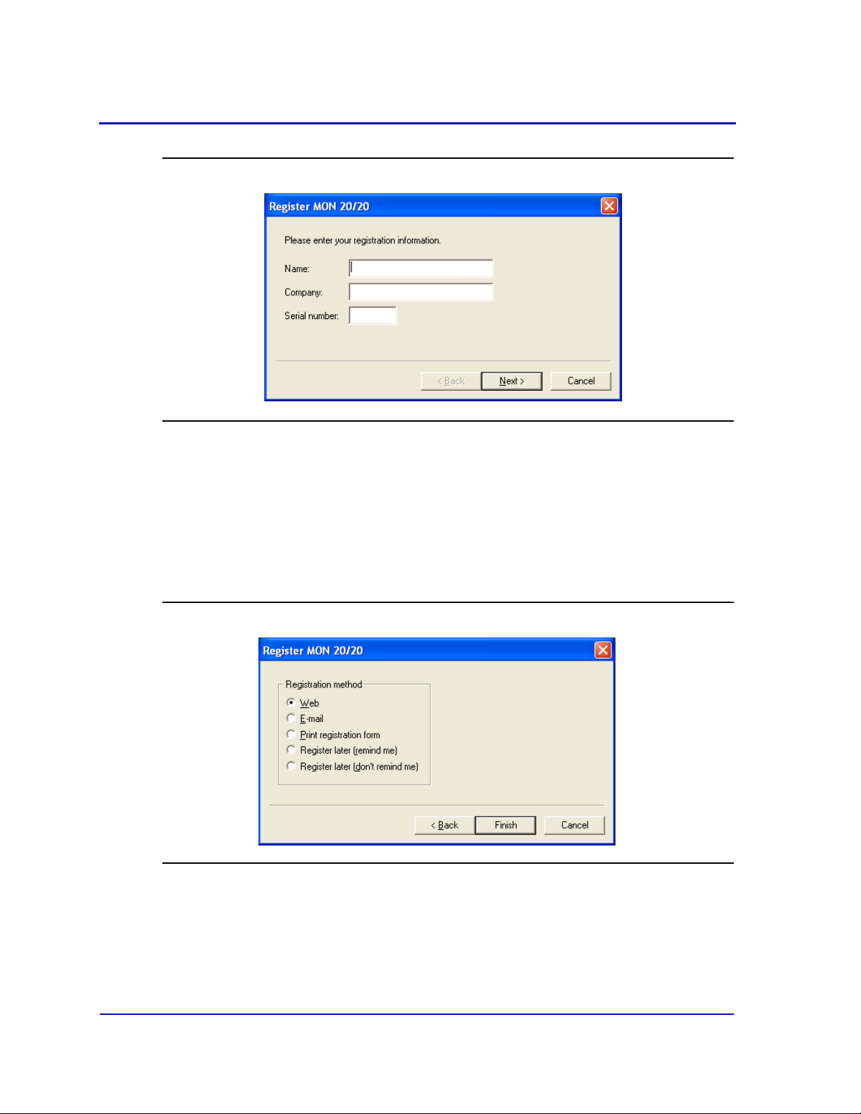
Figure 1-1. The Register MON 20/20 window, page 1
1. Enter your name, your company’s name, and the serial number for
your copy of MON 20/20 into the appropriate fields on the Register
MON 20/20 window.
2. Click Next to continue.
3. Choose the desired registration method by clicking the corresponding
checkbox.
Figure 1-2. The Register MON 20/20 window, page 2
1-8
Page 20
MON20/20 Software for Gas Chromatographs User Manual
OCTOBER 2010 3-9000-745
Note
To delay registration, check Register later (remind me). MON 20/20 will display the
Register MON 20/20 window the next time you start the program. To prevent the
Register MON 20/20 window from displaying with each program startup—and without
registering—check Register later (don’t remind me).
Note
You can register at any time by selecting Register MON 20/20... from the Help menu.
4. Click Finish.
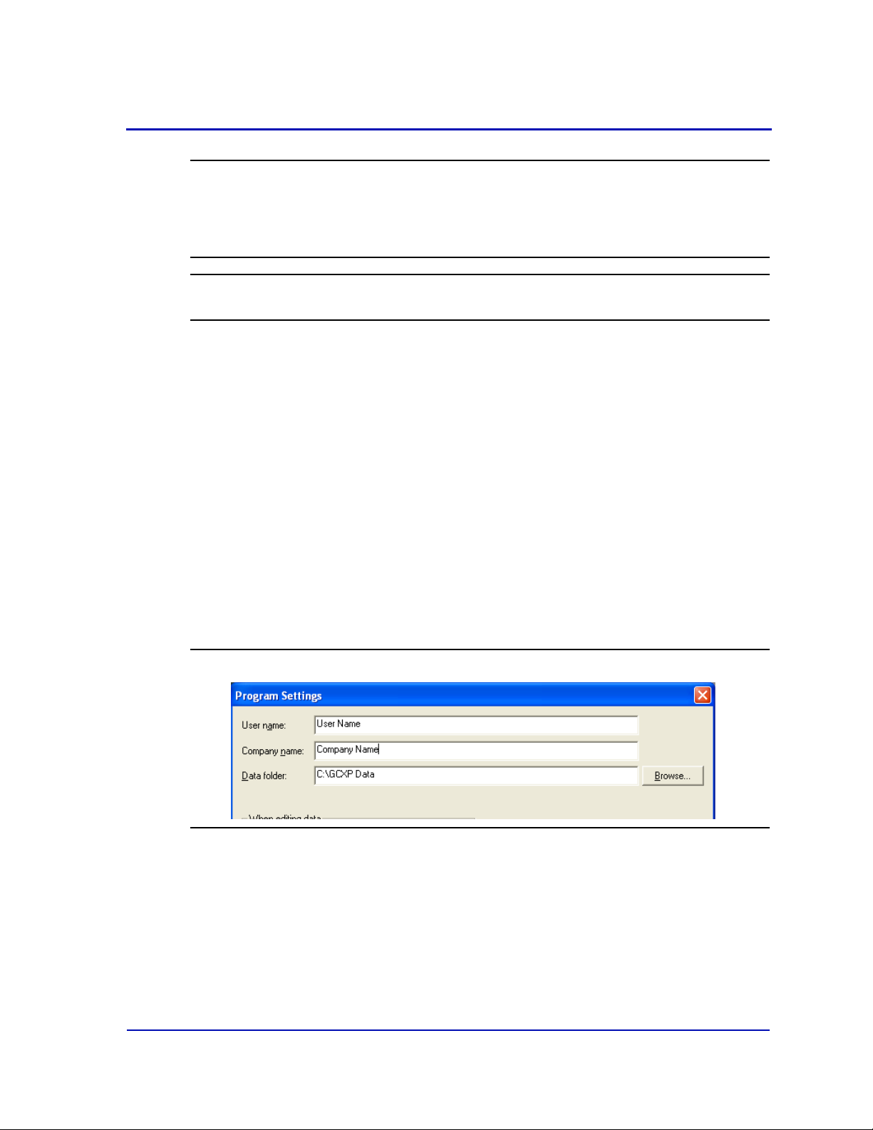
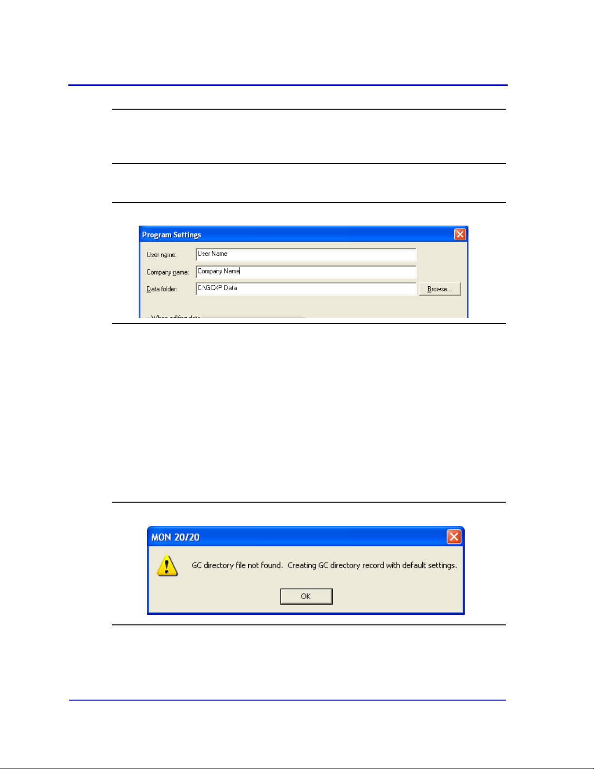
1.2.5 Setting up the data folder
The data folder stores GC-specific files such as reports and
chromatograms. The default location for the data folder is C:\GCXP
Data. If you want MON 20/20 to store its data in a different location—on
a network drive, for instance—do the following:
1. Move the GCXP Data folder to its new location.
2. Select Program Settings... from the File menu.
3. The current location of the data folder displays in the Data Folder
field.
Figure 1-3. The Program Settings window
To change the data folder’s location, click on the Browse button that
is located to the right of the Data Folder field.
4. Use the Browse for Folder window to navigate to the GCXP Data
folder’s new location and click OK.
1-9
Page 21
User Manual MON20/20 Software for Gas Chromatographs
3-9000-745 OCTOBER 2010
Note
Another method for changing the folder location is to type the folder’s location into the
Data Folder field and press ENTER. When the “Create the folder?” message appears,
click Yes.
5. The Data Folder field updates to display the new location.
Figure 1-4. The Program Settings window
1.2.6 Configuring MON 20/20 to connect to a gas chromatograph
MON 20/20 can communicate via its Ethernet connection with any
Ethernet-ready gas chromatograph.
To congifure MON 20/20 to connect to a GC, do the following:
1. Select GC Directory... from the File menu.
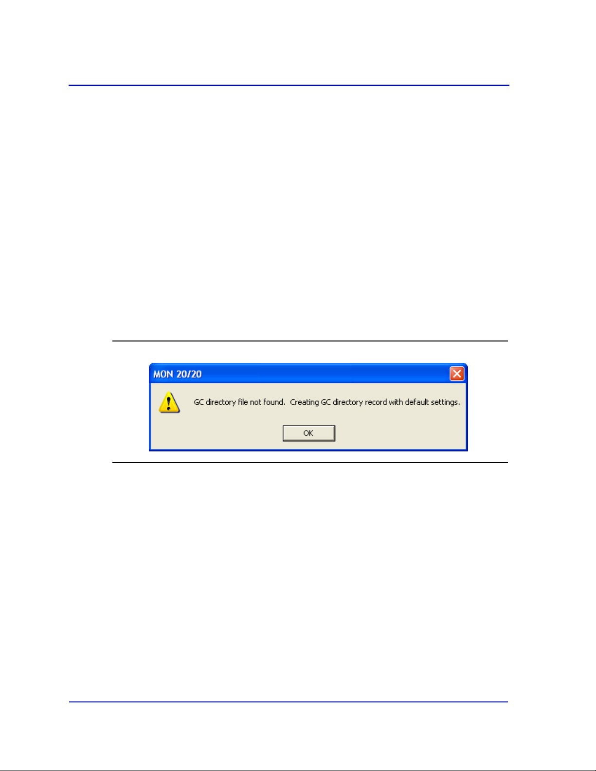
If this is the first time that this option was selected, you will get the
following error message:
Figure 1-5. “GC directory file not found” message
1-10
Page 22
MON20/20 Software for Gas Chromatographs User Manual
OCTOBER 2010 3-9000-745
If you get the “GC directory file not found” message, click OK. The GC
Directory window appears and displays a table containing an
inventory of the GCs to which MON 20/20 can connect.
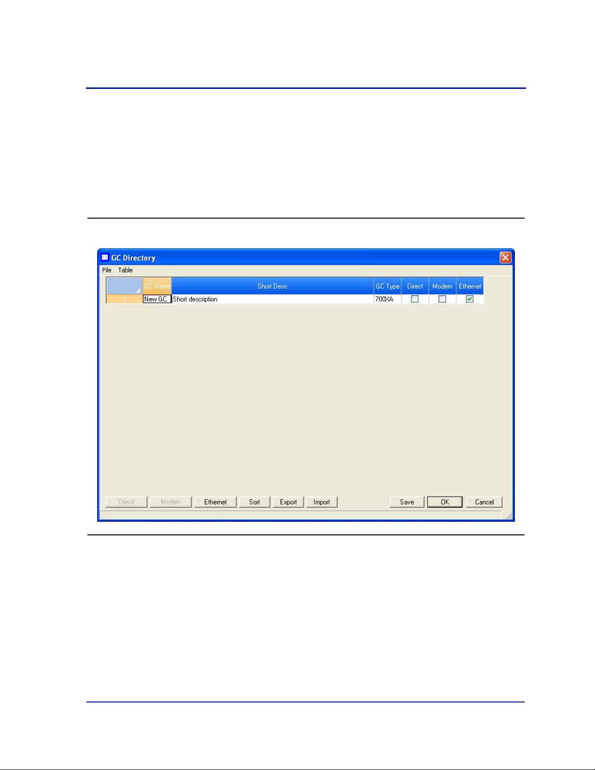
2. If you are configuring the first GC connection for MON 20/20, there
will be on one generic GC record listed in the window. To add another
record, select Add from the GC Directory window’s File menu. A new
row will be added to the bottom of the table.
Figure 1-6. The GC directory window
3. Click in the GC Name field and enter the name for the GC to which
you want to connect.
4. Optionally, you can double-click in the Short Desc field and enter
pertinent information about the GC to which you want to connect,
such as its location. You can enter up to 100 characters in this field.
1-11
Page 23
User Manual MON20/20 Software for Gas Chromatographs
3-9000-745 OCTOBER 2010
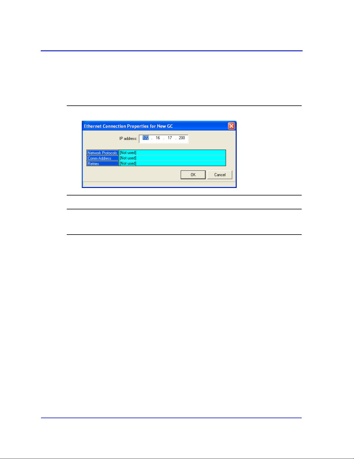
5. Select Ethernet. The Ethernet Connection Properties for New GC
window appears.
6. In the IP address field, enter the IP address of the GC to which you
want to connect.
Figure 1-7. The Ethernet Connection Properties for New GC window
Note
If you type in an invalid IP address, you will get an error message when MON 20/20
attempts to connect to the GC.
7. Click OK. When the Save changes? message appears, click Yes.
8. Repeat steps 2 through 7 for any other GCs to which you want to
connect.
9. To delete a GC from the table, select the GC and then select Delete
from the File menu.
10.To copy a GCs configuration information into a new row, select the GC
and then select Insert Duplicate from the File menu.
11.To insert a row below a GC, select the GC and then select Insert from
the File menu.
12.To sort the table alphebetically, select Sort from the Table menu or
click Sort from the GC Directory window.
13.To copy the list of GCs to the clipboard to be pasted into another
application, select Copy Table to Clipboard from the Table menu.
14.To print the list of GCs, select Print Table... from the Table menu.
1-12
Page 24
MON20/20 Software for Gas Chromatographs User Manual
OCTOBER 2010 3-9000-745
15.To save the changes and keep the window open click Save from the
GC Directory window. To save the changes and close the window,
click OK. When the Save changes? message appears, click Yes.
For more details about configuring MON 20/20 connections, see
“Configuring the gas chromatograph’s Ethernet port” on page 4-95.
1.2.7 Importing or exporting the GC directory table
The GC Directory table, which contains the list of GCs that are currently
configured for MON 20/20, can be saved as a DAT file to a PC or other
storage media such as a compact disk or flash drive. This DAT file can be
used to restored the GC directory information to the original application,
or it can be used to quickly and easily configure other copies of MON 20/
20 that are installed on other computers.
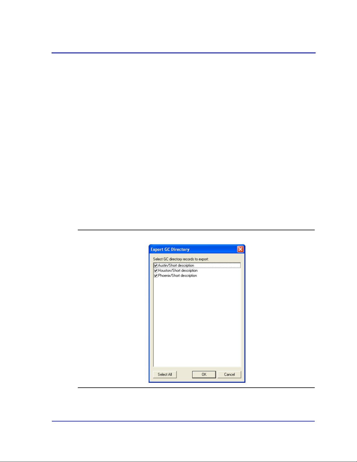
To save the GC Directory table to the PC, do the following:
1. Click Export. The Export GC Directory window displays.
Figure 1-8. The Export GC Directory
1-13
Page 25
User Manual MON20/20 Software for Gas Chromatographs
3-9000-745 OCTOBER 2010
2. Select the checkbox for each gas chromatograph who information you
want to save. If you want to save the entire list, click Select All.
3. Click OK. The Export GC Directory File save as dialog displays.
4. Choose a save location. The default location is GCXP Data.
5. The file is automatically given the name of
GC_DIRECTORY_EXPORT.DAT. If you prefer a different name,
type it into the File name field.
6. Click Save.
To import a GC Directory file, do the following:
1. Select GC Directory... from the File menu.
If this is the first time that this option was selected, you will get the
following error message:
Figure 1-9. “GC directory file not found” message
If you get the “GC directory file not found” message, click OK. The GC
Directory window appears
2. Click Import. The Import GC Directory File dialog displays.
3. Locate the GC directory file and select it. Click Open. The GC
Directory window reappears with the list of newly configured GCs
displayed in the GC Directory table.
1-14
Page 26
MON20/20 Software for Gas Chromatographs User Manual
OCTOBER 2010 3-9000-745
1.2.8 Launching MON 20/20 from the SNAP-ON for DeltaV
This section assumes that DeltaV is installed on the PC along with MON
20/20.
Note
To successfully use MON 20/20 SNAP-ON for DeltaV, you must be familiar with using
the DeltaV digital automation system.
To start MON 20/20, do the following:
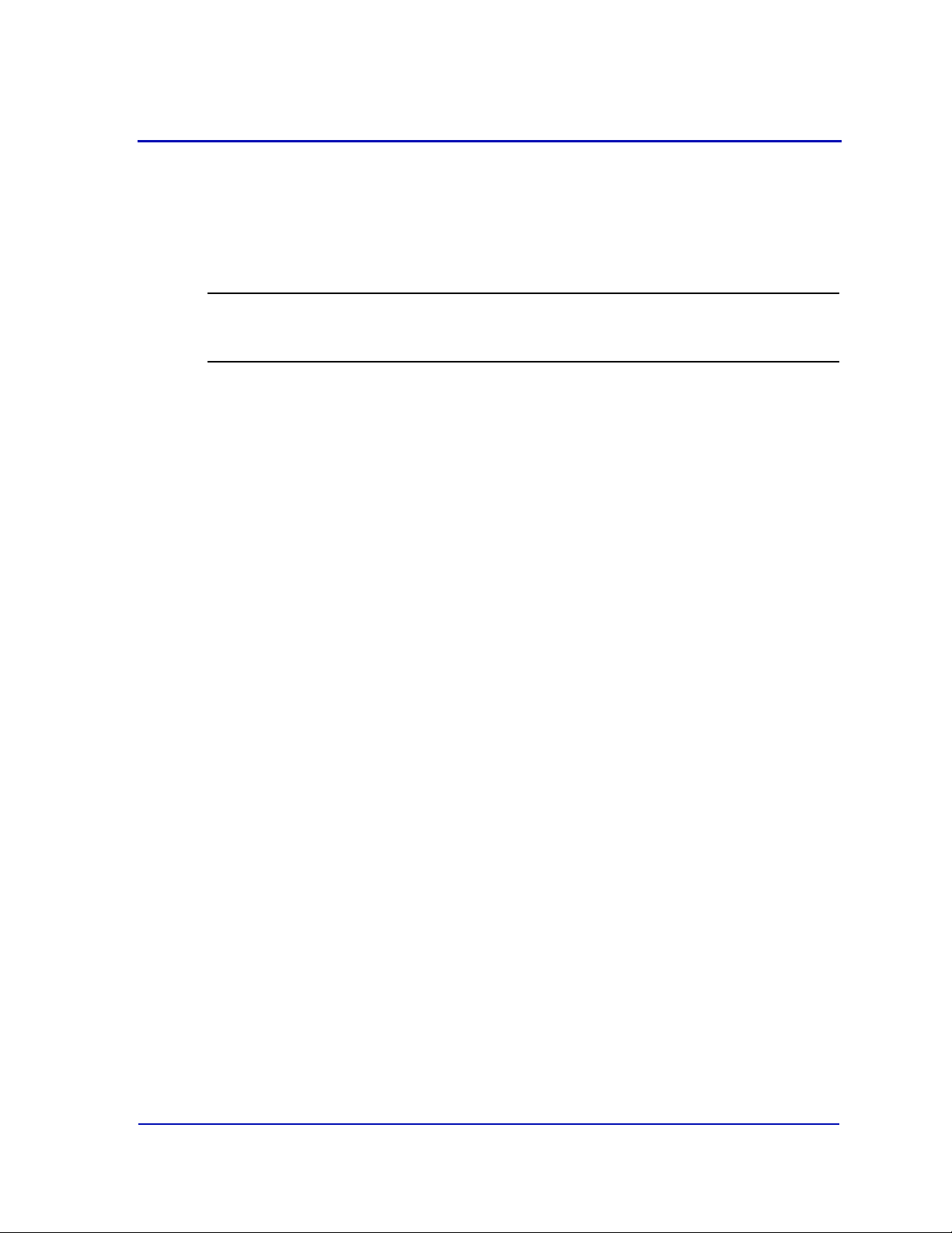
1. Start the DeltaV Explorer by clicking on its desktop icon or by clicking
the Start button and selecting DeltaV → Engineering → DeltaV
Explorer.
2. In the Device Connection View, open device icons by clicking once on
each icon. Follow the path of connections until you locate the desired
gas chromatograph icon.
1-15
Page 27
User Manual MON20/20 Software for Gas Chromatographs
3-9000-745 OCTOBER 2010
Figure 1-10. The Device Connection View
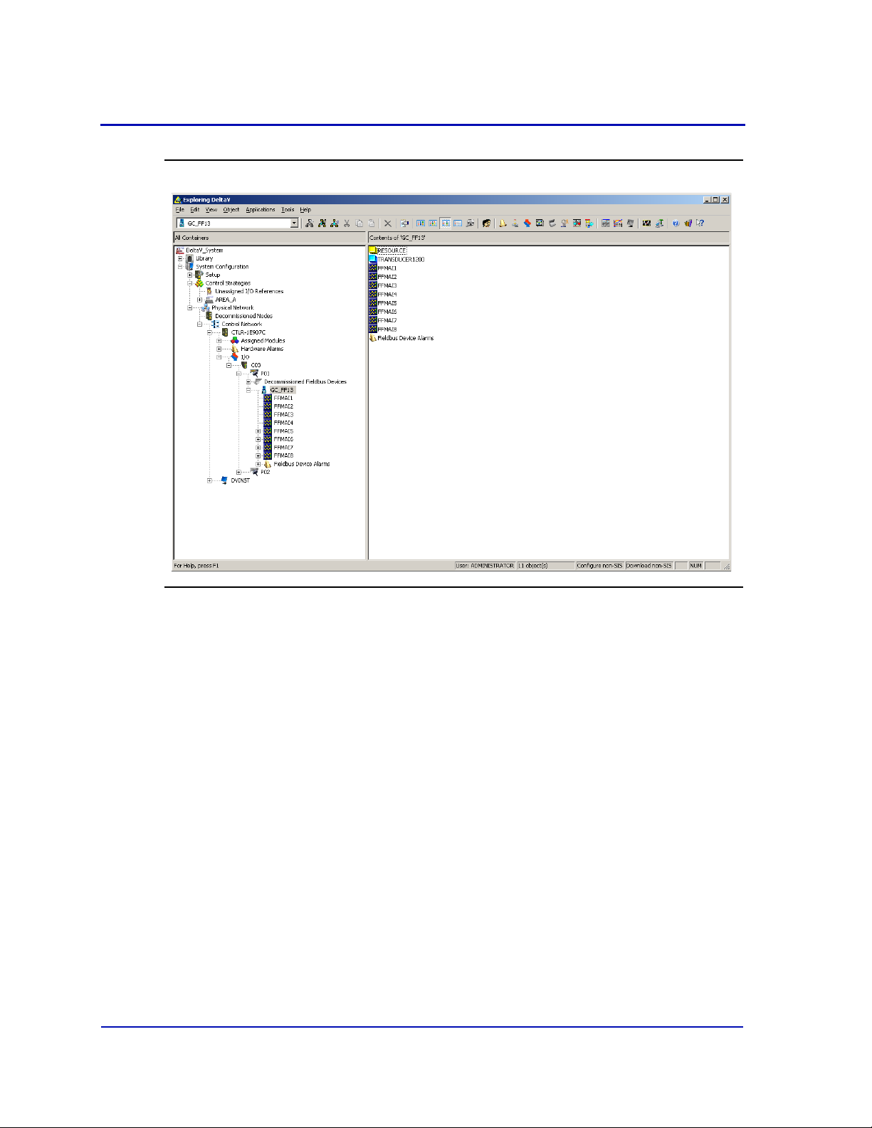
3. Right-click on a connected gas chromatograph icon to display the
context menu.
1-16
Page 28
MON20/20 Software for Gas Chromatographs User Manual
OCTOBER 2010 3-9000-745
Figure 1-11. Right-click to view context menu
4. Select SNAP-ON/Linked Apps → Launch MON 20/20. MON 20/20
starts and connects automatically to the GC.
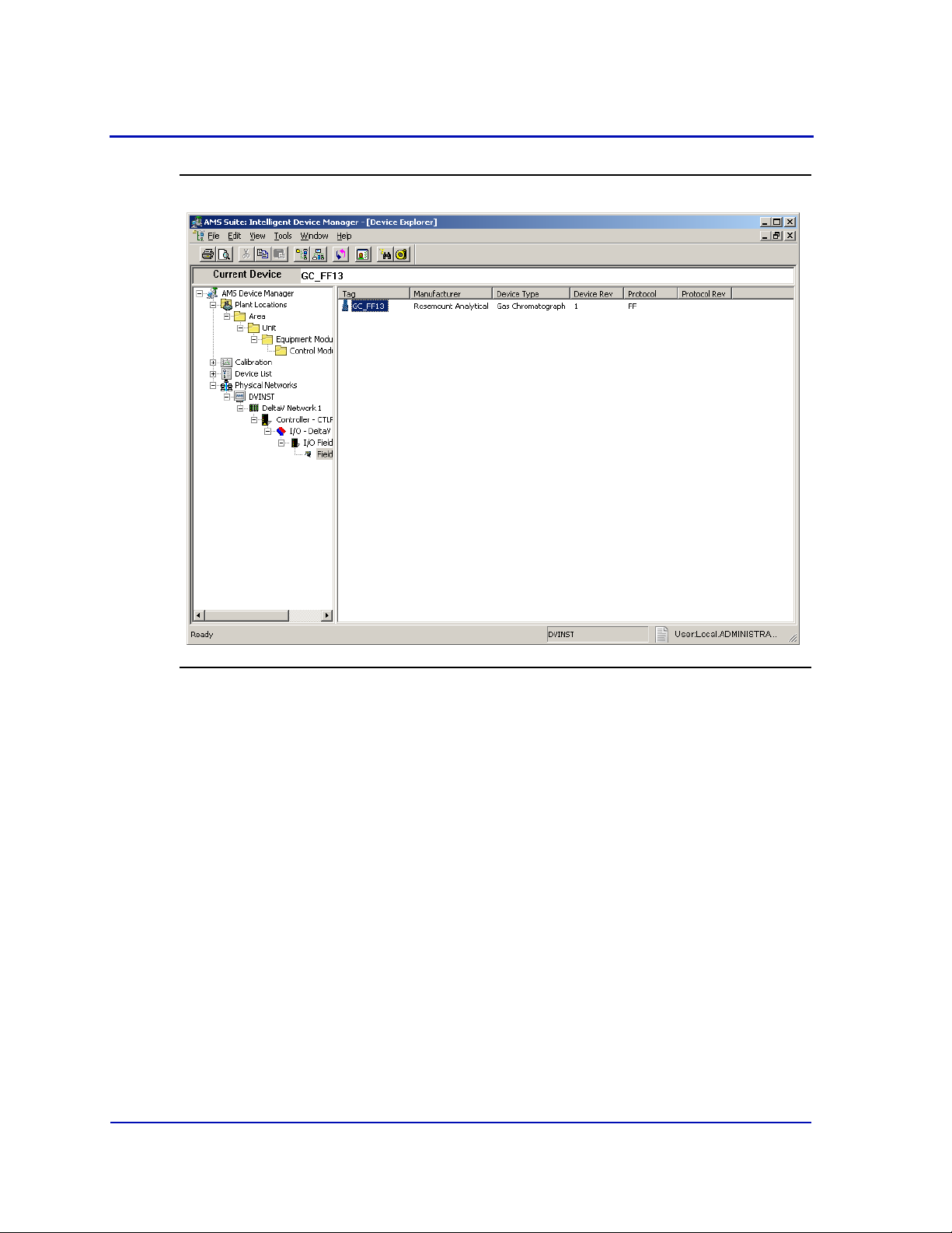
1.2.9 Launching MON 20/20 from the AMS Device Manager
This section assumes that DeltaV and AMS are installed on the PC along
with MON 20/20.
To start MON 20/20, do the following:
1. Start the AMS Device Manager by clicking on its desktop icon or by
clicking the Start button and selecting AMS Device Manager → AMS
Device Manager.
1-17
Page 29
User Manual MON20/20 Software for Gas Chromatographs
3-9000-745 OCTOBER 2010
Figure 1-12. Device Explorer
2. In the Device Connection View, open device icons by clicking once on
each icon. Follow the path of connections until you locate the desired
gas chromatograph icon.
3. Right-click on a connected gas chromatograph icon to display the
context menu.
1-18
Page 30
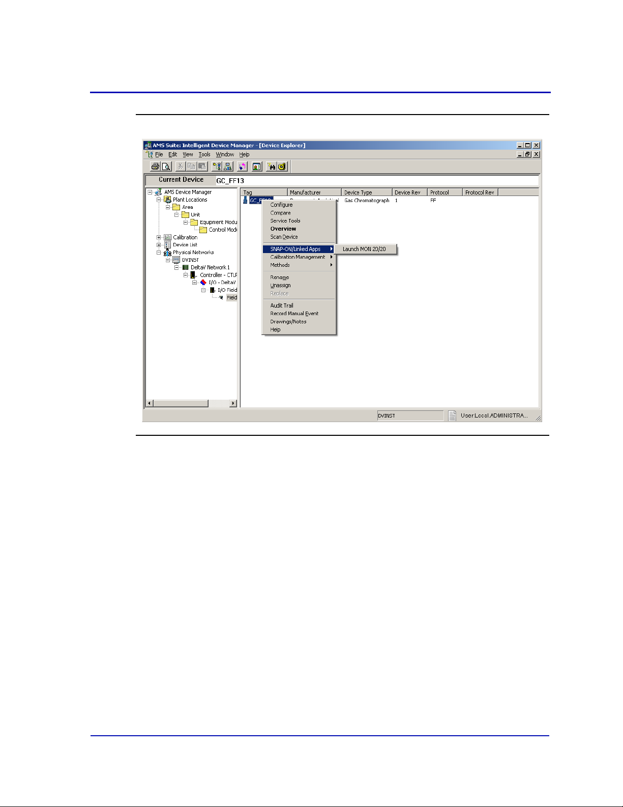
MON20/20 Software for Gas Chromatographs User Manual
OCTOBER 2010 3-9000-745
Figure 1-13. Right-click to view the context menu
4. Select SNAP-ON/Linked Apps → Launch MON 20/20. MON 20/20
starts and connects automatically to the GC.
1-19
Page 31

User Manual MON20/20 Software for Gas Chromatographs
3-9000-745 OCTOBER 2010
1.2.10 The MON 20/20 user interface
MON 20/20 has two areas of interaction: the Control Area, at the top
of the program’s main window, and the GC Status Bar, located at the
bottom of the program’s main window.
Figure 1-14. Features of the MON 20/20 main window
Control Area
GC Status Bar
1-20
Page 32

MON20/20 Software for Gas Chromatographs User Manual
OCTOBER 2010 3-9000-745
The main user interface
The main user interface of the main window contains the menus and
icons that allow you to control MON 20/20 and the GC to which MON
20/20 is connected.
Figure 1-15. The Control Area
Titlebar
Menu bar
Toolbar
Dialog Control Tabs
Titlebar - The Titlebar displays the name of the program, and well as
the program’s connection status. MON 20/20 has the following three
overall status modes:
- Not connected - If MON 20/20 is not connected to a GC, then “MON
20/20” displays in the Titlebar.
- Connected - If MON 20/20 is connected to a GC, then “MON 20/20 Connected to” and the name of the GC and the connection type
displays in the Titlebar.
- Offline Edit - If MON 20/20 is in offline edit mode, then “MON 20/
20 - Offline Edit <filename>” displays in the Titlebar.
• Menu bar - The Menu bar contains the commands that allow you to
control and monitor gas chromatographs.
1-21
Page 33

User Manual MON20/20 Software for Gas Chromatographs
3-9000-745 OCTOBER 2010
• Toolbar - The Toolbar contains shortcut icons for the most important
and/or most often used MON 20/20 commands. From the Toolbar you
can do such things as connect to and disconnect from a GC, view chromatographs, and view help files.
Table 1-1. Function of the shortcut icons on the Toolbar
Connect to a gas chromatograph.
Disconnect from a gas chromatograph.
Open a configuration file.
Print a GC configuration report.
View the Timed Events window.
View the Component Data window.
Clear or acknowledge alarms.
Open the CGM Viewer window.
Begin auto sequencing.
Halt auto sequencing.
Open the About MON 20/20 window.
1-22
Page 34

MON20/20 Software for Gas Chromatographs User Manual
OCTOBER 2010 3-9000-745
• Dialog Control Tabs bar - The Dialog Control Tabs bar contains
four buttons that allow you to manage the behavior of all windows
that are open in the main window. The four buttons are Minimize
All, Maximize All, Restore All, and Close All.
Figure 1-16. The main window showing the function of the Dialog Control Tabs bar
The bar also displays a button for each open window that allows you to
select or deselect that window.
You can hide or display the Toolbar and the Dialog Control Tabs bar by
clicking the appropriate option from the View menu.
1-23
Page 35

User Manual MON20/20 Software for Gas Chromatographs
3-9000-745 OCTOBER 2010
The GC Status Bar
The GC Status Bar of the main window displays useful information about
the status and functioning of the gas chromatograph to which MON 20/20
is connected.
Figure 1-17. The GC Status Bar
The GC Status Bar contains the following sections:
• GC - The first row displays the name of the GC to which MON 20/20 is
connected. If MON 20/20 is not connected to a GC, “Not Connected”
displays in this row. If MON 20/20 loses its connection to the GC,
“Comm Fail” displays in this row, and the program will automatically
try to reconnect. The second row displays status flags such as active
alarms (with red background), unacknowledged alarms (with red
background), or File Edit modes.
• Det # - Each row displays the identification number of the detector
monitoring the alarm status of the connected GC. A GC can have a
maximum of two detectors.
• Mode - Each row displays the mode of the appropriate detector.
Potential modes are: Idle, Auto Cal, Auto Base, Auto Anly, FCal.
• Stream - Each row displays the current stream being analyzed by the
appropriate detector.
• Next - Each row displays the next stream to be analyzed by the
appropriate detector.
• Anly - Each row displays the analysis time for the appropriate
stream.
• Cycle - Each row displays the total cycle time, in seconds, before the
next analysis starts for the appropriate detector.
• Run - Each row displays the amount of time, in seconds, that has
elapsed since the current cycle began for the appropriate detector.
1-24
Page 36

MON20/20 Software for Gas Chromatographs User Manual
OCTOBER 2010 3-9000-745
• GC System - Displays the date and time according to the GC to which
MON 20/20 is connected. The date and time displayed may be
different from the user’s date and time, depending on the physical
location of the GC.
• FID Flame Status - Displays the status of the FID flame. Options
are OFF with red background, ON with green background, and OVER
TEMP with red background. The FID Flame Status indicator only
displays on the GC Status Bar when the GC to which MON 20/20 is
connected contains an FID detector.
You can hide or display the GC Status Bar by clicking GC Status Bar
from the View menu.
1.2.11 Connecting to a gas chromatograph
To connect to a gas chromatograph, you must log on to it first. Most of
MON 20/20’s menus and options are inactive until you have logged on to a
GC.
To connect to a GC, do the following:
1. There are two ways to start the process:
(a.) On the Toolbar, click .
(b.) Select Connect... from the Chromatograph menu.
2. The Connect to GC dialog, which displays a list of all the GCs to which
you can connect, appears.
1-25
Page 37

User Manual MON20/20 Software for Gas Chromatographs
3-9000-745 OCTOBER 2010
Figure 1-18. The Connect to GC window
1-26
Note
If you want to edit the connection parameters for one or all GCs listed in the Connect to
GC window, click Edit Directory. The GC Directory window will appear. See
“Configuring MON 20/20 to connect to a gas chromatograph” on page 1-10 for more
information.
Click the Ethernet button beside the GC to which you want to connect.
Page 38

MON20/20 Software for Gas Chromatographs User Manual
OCTOBER 2010 3-9000-745
3. The Login dialog appears.
Figure 1-19. The Login window
Note
All GCs are shipped with two default user names: daniel and emerson. A user pin is
not required when using either of these user names and both user names allow
administrator-level access to the GC. To add a user pin to either of these user names or
for information about creating and edit user names in general, see “Managing users” on
page 7-17.
Enter a user name and user PIN and click OK. Once connected, the
name of the GC appears under the GC column in the GC Status Bar.
Figure 1-20. The GC Status Bar showing a successful connection to a GC
Note
If you enter an invalid user name or password, the Login dialog will close without
connecting to the GC.
1-27
Page 39

User Manual MON20/20 Software for Gas Chromatographs
3-9000-745 OCTOBER 2010
1.2.12 Disconnecting from a gas chromatograph
Disconnecting from a GC will automatically log you off of the GC.
To disconnect from a gas chromatograph, do one of the following:
• On the Toolbar, click .
• Select Disconnect from the Chromatograph menu.
Note
If you are connected to a GC and want to connect to a different GC, it is not necessary to
disconnect first; simply connect to the second GC, and in the process MON 20/20 will
disconnect from the first GC.
1.3 Keyboard commands
You can use the following keyboard keystrokes throughout the program:
Table 1-2. Frequently Used Keystrokes
Keystroke Action
ARROW
keys
DELETE • Deletes the character after cursor.
ENTER Activates the default control element (e.g., the OK button) in current window.
ESC Exits application or active window without saving data.
F1 Accesses context-sensitive help topics.
INSERT • Toggles between insert and type-over mode in selected cell.
SHIFT+TAB Moves to previous control element (e.g., button) or data field in window; see
Moves cursor:
• Left or right in a data field.
• Up or down in a menu or combo box.
• Up or down (column), left or right (row) through displayed data entries.
• Deletes selected rows from a table or return row values to the default
settings.
• Inserts a new row above the highlighted row.
TAB description.
1-28
Page 40

MON20/20 Software for Gas Chromatographs User Manual
OCTOBER 2010 3-9000-745
Table 1-2. Frequently Used Keystrokes (Continued)
Keystroke Action
SPACE Toggles settings (via radio buttons or check boxes).
TAB Moves to the next control element (e.g., button) in the window; to use TAB key
to move to next data field, select Program Settings... from the File menu
and clear the Tab from spreadsheet to next control check box.
You can use the following function keys from the main window:
Table 1-3. Main menu function keys
Function
Key
Action
F2 Starts the Auto-Sequencing function. See “Auto sequencing” on page 6-2 for
more information.
F3 Halts the GC (e.g., an analysis run) at the end of the current cycle. See “Halting
an analysis” on page 6-1 for more information.
F5 Displays the Timed Event table per specified stream. See “Managing timed
events” on page 4-17 for more information.
F6 Displays the Component Data table per specified stream. See “Managing
Component Data Tables” on page 4-5 for more information.
F7 Displays the chromatogram for the sample stream being analyzed. See
“Viewing a live chromatogram” on page 2-3 for more information.
F8 Displays any chromatogram stored in the GC Controller. See “Viewing an
archived chromatogram” on page 2-5 for more information.
1-29
Page 41

User Manual MON20/20 Software for Gas Chromatographs
3-9000-745 OCTOBER 2010
1.4 Procedures guide
Use the following table to look up the related manual section, menu path
and, if appropriate, the keystroke for a given procedure.
Table 1-4. MON 20/20 Task List
Task or Data Item Section(s) Menu Path [Keystroke]
24-hour average, component(s)
measured
Add a gas chromatograph 1.2.6 File → GC Directory
Alarms, related components 4.2
Alarms, stream number(s)
programmed
Analysis Report (on/off) 5.7.3 Logs/Reports → Printer Control...
Analysis time 4.3.4 Application → Timed Events... [F5]
Starting or ending auto-calibration 4.10 Application → Streams...
Auto-calibration interval 4.10 Application → Streams...
Auto-calibration start time 4.10 Application → Streams...
Autocal time 4.10 Application → Streams...
Baseline 4.10 Application → Streams...
4.5.2 Application → Calculations →
Averages...
Application → Component Data... [F6]
4.8
3.4
4.8 Application → Limit Alarms → User...
Application → Limit Alarms → User...
Hardware → Discrete Outputs...
Base pressure used for calculations 4.10 Application → Streams...
Calibration concentration 4.2 Application → Component Data... [F6]
Calibration cycle time 4.3.4 Application → Timed Events... [F5]
Calibration runs, number averaged 4.10 Application → Streams...
Calibration runs, number of 4.10 Application → Streams...
Calibration stream number 4.10 Application → Streams...
1-30
Page 42

MON20/20 Software for Gas Chromatographs User Manual
OCTOBER 2010 3-9000-745
Table 1-4. MON 20/20 Task List
Task or Data Item Section(s) Menu Path [Keystroke]
Communications 4.12 Application → Communication...
Application → Ethernet Ports...
Component code and name 4.2 Application → Component Data... [F6]
Component full scale (for output) 4.1
3.6
Component(s) programmed for
input
Component(s) programmed for
output
3.5
3.3
4.8
3.6
3.4
Application → System...
Hardware → Analog Outputs...
Application → Analog Inputs...
Application → Discrete Inputs...
Application → Limit Alarms → User...
Hardware → Analog Outputs...
Hardware → Discrete Outputs...
Component, retention time 4.2 Application → Component Data... [F6]
Component zero (for output) 3.6 Hardware → Analog Outputs...
Compressibility (on/off) 4.5.1 Application → Calculations → Control...
Current date 2.6 Chromatograph → View/Set GC Time...
Current time 2.6 Chromatograph → View/Set GC Time...
Cycle time 4.3.4 Application → Timed Events... [F5]
Delete alarms 4.8
5.1
Delete component from component
4.2 Application → Component Data... [F6]
Application → Limit Alarms...
Logs/Reports → Alarms → Alarm Log...
list
Delete inhibit, integration, peak
4.3.4 Application → Timed Events... [F5]
width
Delete output(s) 3.6
3.4
Hardware → Analog Outputs...
Hardware → Discrete Outputs...
Enable or disable multi-user write 4.1 Application → System...
Existing alarm(s) 5.1 Logs/Reports → Alarms → Alarm Log...
Full-scale value (for input) 3.5 Hardware → Analog Inputs...
GPM liquid equivalent (on/off) 4.5.1 Application → Calculations → Control...
1-31
Page 43

User Manual MON20/20 Software for Gas Chromatographs
3-9000-745 OCTOBER 2010
Table 1-4. MON 20/20 Task List
Task or Data Item Section(s) Menu Path [Keystroke]
Height or area measurement
4.2 Application → Component Data... [F6]
method
High alarm 4.8 Application → Limit Alarms → User...
(Analyzer) I.D. 4.1 Application → System...
Inhibit on-off times 4.3.4 Application → Timed Events... [F5]
Input(s) being used 3.5
3.3
Hardware → Analog Inputs...
Hardware → Discrete Inputs...
Integration on-off times 4.3.4 Application → Timed Events... [F5]
Low alarm 4.8 Application → Limit Alarms → User...
Mole percent (on/off) 4.5.1 Application → Calculations → Control...
Normalization (on/off) 4.5.1 Application → Calculations → Control...
Outputs being used 4.8
3.6
3.4
Application → Limit Alarms → User...
Hardware → Analog Outputs...
Hardware → Discrete Outputs...
Peak width, on time 4.3.4 Application → Timed Events... [F5]
Ratio (on/off) 4.6 Application → Calculations → User
Defined...
Ratio denominator 4.6 Application → Calculations → User
Defined...
Ratio, stream number(s) 4.6 Application → Calculations → User
Defined...
Relative density (on/off) 4.5.1 Application → Calculations → Control...
Response factor 4.2 Application → Component Data... [F6]
Response factor, percent deviation 4.2 Application → Component Data... [F6]
Retention time, percent deviation 4.2 Application → Component Data... [F6]
Spectrum gain 4.3.3 Application → Timed Events... [F5]
1-32
Page 44

MON20/20 Software for Gas Chromatographs User Manual
OCTOBER 2010 3-9000-745
Table 1-4. MON 20/20 Task List
Task or Data Item Section(s) Menu Path [Keystroke]
Stream number(s) (for output) 4.8
3.6
3.4
Stream sequences skipped, number 4.1
4.10
Streams analyzed, number 4.1
4.10
Streams analyzed, sequence 4.1
4.10
Valve on/off times 4.3.1 Application → Timed Events... [F5]
Weight percent (on/off) 4.5.1 Application → Calculations → Control...
Wobbe value (on/off) 4.5.1 Application → Calculations → Control...
Zero value (for input) 3.5 Hardware → Analog Inputs...
Application → Limit Alarms → User...
Hardware → Analog Outputs...
Hardware → Discrete Outputs...
Application → System...
Application → Streams...
Application → System...
Application → Streams...
Application → System...
Application → Streams...
1.5 Configuring a gas chromatograph
Use the File menu to edit, save, and restore configuration files.
1.5.1 Editing a configuration file
To edit a configuration file, do the following:
1. Disconnect from the GC.
2. Select Open Configuration File... from the File menu. The Open
dialog displays. Configuration files are saved with the .xcfg
extension.
3. Locate and select the configuration file that you want to edit and click
Open. MON 20/20 opens the file in offline edit mode.
1-33
Page 45

User Manual MON20/20 Software for Gas Chromatographs
3-9000-745 OCTOBER 2010
Figure 1-21. MON 20/20 in offline edit mode
1-34
4. Use the Application and Hardware menu commands to edit the
GC’s settings. For more information on these commands, see
Section 3 and Section 4.
5. When finished configuring the GC, click to disconnect from the
GC and to save the changes to the configuration file and to leave
offline edit mode.
Page 46

MON20/20 Software for Gas Chromatographs User Manual
OCTOBER 2010 3-9000-745
1.5.2 Saving a gas chromatograph’s current configuration
Configuration files are saved with the .xcfg extension. To save a GC’s
current configuration to a PC, do the following:
1. Select Save Configuration (to PC)... from the File menu. The Save
as dialog displays.
2. Give the file a descriptive name or use the pre-generated file name
and navigate to the folder to which you want to save the file.
3. Click Save.
1.5.3 Importing a configuration file
To import a new configuration into a GC or to restore a GC’s previous
configuration, do the following:
Note
The current configuration will be overwritten, so be sure to save it before importing a
new or previous configuration.
Note
The GC should be in Idle mode while performing this task.
1. Select Restore Configuration (to GC)... from the File menu. The
Open dialog displays. Configuration files are saved with the .xcfg
extension.
2. Locate and select the configuration file that you want to import and
click Open. The file’s data is loaded into the GC.
1-35
Page 47

User Manual MON20/20 Software for Gas Chromatographs
3-9000-745 OCTOBER 2010
1.6 Restoring the GC to its factory settings
The GC’s default timed event, component data and validation data tables
are created at the factory and are not accessable by users. To restore
these tables to their default values, do the following:
Note
The GC should be in Idle mode while performing this task.
1. With the GC idle, select Restore to Factory Settings... from the
File menu. The following warning message displays:
Figure 1-22. Restore to Factory Settings warning message
1-36
2. Click Yes. The MON 20/20 restores the default values to the GC’s
data tables. When the process is completed, the following message
displays:
Figure 1-23. Restoration completed message
3. Click OK.
Page 48

MON20/20 Software for Gas Chromatographs User Manual
OCTOBER 2010 3-9000-745
1.7 Configuring your printer
Select Print Setup... from the File menu to configure the settings for the
printer connected to your PC. These settings will apply to any print job
queued from MON 20/20, such as the reports that are configured by the
Printer Control. See “Printing reports automatically” on page 5-44 for
information.
Figure 1-24. The Print Setup dialog
The settings available depend on the printer model. Refer to the printer
manufacture’s user manual for more information.
Note
Your new configuration will be cleared, i.e., the settings will return to the default values,
when you exit MON 20/20.
1-37
Page 49

User Manual MON20/20 Software for Gas Chromatographs
3-9000-745 OCTOBER 2010
1.8 Using online help
Currently, the online help feature contains all user information and
instructions for each MON 20/20 function as well as the MON 20/20
system.
To access the online help, do one of the following:
•Press F1 to view help topics related to the currently active dialog or
function.
• Select Help Topics from the Help menu to view the help contents
dialog.
1.9 Operating modes for MON 20/20
The GC supports two different operating modes. Each mode allows the
GC to analyze data from a given number of detectors, streams, and
methods, as detailed in Table 1-5.
Table 1-5. Operating Modes for MON 20/20
Mode ID
Number
0111
1211
Detectors
Supported
Streams
Supported
1.10 Viewing the Physical Name column
Most MON 20/20 hardware windows contain a hidden column called
Physical Name that lists the default name for the associated GC device,
such as the analog inputs or electronic pressure controls. It might be
useful to know a device’s physical name while troubleshooting.
Methods
Supported
1-38
Page 50

MON20/20 Software for Gas Chromatographs User Manual
OCTOBER 2010 3-9000-745
To view hidden columns, do the following:
1. Select Program Settings... from the File menu. The Program
Settings window displays.
Figure 1-25. The Program Settings window
2. Select the Show Physical Names checkbox.
1-39
Page 51

User Manual MON20/20 Software for Gas Chromatographs
3-9000-745 OCTOBER 2010
3. Click OK. The Physical Name column now will be visible on all
windows that have the column, such as the Heater window shown in
the example below.
Figure 1-26. The Heater window showing Physical Name column
1.11 Selecting the GC’s networking protocol
MON 20/20 can connect to the GC using one of two networking protocols:
PPP or SLIP. If the version level of the GC’s firmware is 1.2 or lower,
MON 20/20 should be configured to use the SLIP protocol; otherwise, the
PPP protocol should be used.
To select the GC’s networking protocol, do the following:
1. Select Program Settings... from the File menu. The Program
Settings window displays.
1-40
Page 52

MON20/20 Software for Gas Chromatographs User Manual
OCTOBER 2010 3-9000-745
Figure 1-27. The Program Settings window
2. To use the PPP protocol, make sure the Use PPP protocol for serial
connection (use SLIP if unchecked) checkbox is selected; to use the
SLIP protocol, make sure the Use PPP protocol for serial connection
(use SLIP if unchecked) checkbox is not selected.
3. Click OK.
1-41
Page 53

User Manual MON20/20 Software for Gas Chromatographs
3-9000-745 OCTOBER 2010
1.12 Using the context-sensitive variable selector
The MON 20/20 method for selecting variables for calculations and other
purposes is based on a simple, self-contained system.
Figure 1-28. Example of a context-sensitive variable selector
The context-sensitive variable selector consists of a first-level element,
called the context, that is followed by a series of tiered, drop-down lists.
The options available from the drop-down lists depend upon the context
element.
The following example explains how to use the context-sensitive variable
selector to select a user alarm variable:
1. Click on the second-level drop-down list. The full list of available
streams displays.
Figure 1-29. Second-level drop-down list
2. Select the stream you want to use for the alarm.
1-42
Page 54

MON20/20 Software for Gas Chromatographs User Manual
OCTOBER 2010 3-9000-745
3. Click the third-level drop-down list. The full list of available user
alarm variables displays.
Figure 1-30. Third-level drop-down list
4. Select the variable you want to use for the alarm. If there are
components associated with the variable, the fourth-level drop-down
list will display.
5. If displayed, click the fourth-level drop-down list. The full list of
available components displays.
Figure 1-31. Fourth-level drop-down list
6. Select the component you want to use for the alarm.
7. Click [Done]. The context-sensitive variable selector closes and the
variable displays in the Variable field.
1-43
Page 55

User Manual MON20/20 Software for Gas Chromatographs
3-9000-745 OCTOBER 2010
Figure 1-32. Variable selected
1-44
Page 56

Section 2: Using the chromatograph functions
For viewing and managing chromatograms,
MON 20/20 is flexible and straighforward.
This chapter shows you how to connect to and
disconnect from a gas chromatograph. This
chapter also shows you how to access the
Chromatogram Viewer, as well as to use it to
view, print and manipulate various types of
chromatograms.
Finally, this chapter explains how to set a gas chromatograph’s date and
time.
2.1 Viewing chromatograms
Use the Chromatogram Viewer to display and print live, archived, or
saved chromatograms. There is no limit to the number of archived and
saved chromatograms that can be displayed at once; however, to
maximize performance, the number of chromatograms displayed should
be limited to 25 or less. The Chromatogram Viewer can display all three
types of chromatograms together, alone, or in any combination.
The Chromatogram Viewer contains a host of information about both
current and past GC analyses, and it contains just as many ways of
editing and manipulating that data.
2-1
Page 57

User Manual MON20/20 Software for Gas Chromatographs
3-9000-745 OCTOBER 2010
2.1.1 Data displayed in the chromatogram window
Figure 2-1. The chromatogram window
trace #1
retention time
peak detection
timed event marker
marker
trace #1
trace #2
The following elements are displayed in the chromatogram window:
• The chromatogram
. A trace is the graphical representation of the
analysis results from a single detector; a chromatogram is the
collection of all traces and associated data that are generated by a gas
chromatograph’s detector or detectors. Each trace displays in a
different color.
• Retention times. The retention time for each peak displays above it.
• Baselines. The baseline projects from the beginning to the end of a
peak. The baseline can be turn on or off by clicking Baselines.
2-2
Page 58

MON20/20 Software for Gas Chromatographs User Manual
OCTOBER 2010 3-9000-745
• Timed event markers. These markers, which correspond to events
from the Timed Events table, display on the chromatogram as black
marks descending from the trace-line. There are three types of timed
event markers:
- Valve events display as long descending marks.
- Integration events display as medium descending marks.
- Spectrum gain events display as short descending marks.
• Peak detection markers. These markers display on the chromatogram
as black marks ascending from the trace-line. Each peak has two
peak detection markers: one at its beginning and one at its end.
2.1.2 Viewing a live chromatogram
To view a live chromatogram, do the following:
1. Connect to the GC.
2. Select Chromatogram Viewer... from the Chromatograph menu.
Note
Another way to display the Chromatogram Viewer is to click , which is located on
the Toolbar.
WARNING
To prevent the loss of any new data, be sure to save the chromatogram before closing
the Chromatogram Viewer. For more information, see “Saving a chromatogram trace”
on page 2-25.
3. From the Chromatogram Viewer window, check View current CGM.
2-3
Page 59

User Manual MON20/20 Software for Gas Chromatographs
3-9000-745 OCTOBER 2010
Figure 2-2. View Current CGM
The chromatogram displays in the chromatogram window. If the
chromatogram contains one trace, the Det1 checkbox is automatically
checked; if the chromatogram contains two traces, the Det1 and Det2
checkboxes are automatically checked. To remove a trace, uncheck its
detector checkbox.
Each trace that displays is color-coded; use the Chromatogram pulldown menu to select a specific trace.
Figure 2-3. Chromatogram pull-down menu
The list of GC events associated with the production of the
chromatogram, along with each event’s status and time, displays in
the Timed Events table to the right of the chromatogram display
window. The Component Data table, to the lower right of the
chromatogram display window, lists the components measured during
the analysis. These tables are updated in real-time, just as the
chromatogram is.
2-4
Page 60

MON20/20 Software for Gas Chromatographs User Manual
OCTOBER 2010 3-9000-745
Figure 2-4. The Chromatogram Viewer
timed events
chromatogram
window
component
data
Note
By default, the timed events and component data tables are configured to scroll to and
highlight the next occurring event in the analysis cycle. To disable this feature, rightclick on one of the tables and uncheck the Auto Scroll option on the pop-up menu.
2.1.3 Viewing an archived chromatogram
Archived chromatograms are stored on the GC, so you must be logged in
to access them. With MON 20/20 archived chromatograms as old as four
days are available for viewing.
Archived chromatograms are sorted and displayed on four tabbed panes:
• Chromatograms - This view displays all chromatogram types sorted
by time so that the newest file is always listed first. This view can be
further configured to display only the files from the last five runs for
each stream, or to display all the files that are stored on the GC.
2-5
Page 61

User Manual MON20/20 Software for Gas Chromatographs
3-9000-745 OCTOBER 2010
• Protected chromatograms - Protected chromatograms are never
deleted from the GC. To protect a chromatogram, see “Protecting or
unprotecting an archived chromatogram” on page 2-9.
Note
Protected chromatogram files have a “lock” icon ( ) displayed beside them.
• Final Calibration chromatograms - MON 20/20 will store up to
one year’s worth—or approximately 370—of final calibration
chromatograms; once the limit is reached, MON 20/20 will delete the
oldest non-protected final calibration chromatogram for each new final
calibration chromatogram that is created. If multiple final calibration
chromatograms are created on the same day, the last chromatogram
created is archived, unless MON 20/20 has been configured to archive
all final calibration chromatograms.
Note
See “Managing the system” on page 4-2 to learn how to configure MON 20/20’s archiving
behavior.
2-6
Page 62

MON20/20 Software for Gas Chromatographs User Manual
OCTOBER 2010 3-9000-745
Final Validation chromatograms - These chromatograms are treated
in the same manner as final calibration chromatogram files.To view one
or more archived chromatograms, do the following:
1. Click GC Archive. The Select archive file(s) window appears.
Figure 2-5. The Select archive file(s) window
The files can be sorted by date, file name, analysis type, time, or
stream number by clicking the appropriate column header. By
default, they are sorted by date, with the newest file listed first.
Note
By default, only recent chromatograms—that is, the last five runs for each stream—are
displayed. To view all archived chromatograms, click All. To return to viewing only
recent chromatograms, click Recent.
2-7
Page 63

User Manual MON20/20 Software for Gas Chromatographs
3-9000-745 OCTOBER 2010
2. Select one or more archive files by clicking them. Use the SHIFT or
CTRL key to make multiple selections.
Note
To save the selected files to the PC, select the Download and save selected
chromatograms check box and click Download & Save.
3. Click Download & Show. The Select window displays for each
chromatogram that contains data from more than one detector.
Figure 2-6. The Select window
4. For each chromatogram, double-click either “Detector 1”, “Detector 2”,
or “Both” from the Select window.
MON 20/20 plots the archived chromatogram(s) and the corresponding
data displays in the timed event and component data tables.
2-8
Page 64

MON20/20 Software for Gas Chromatographs User Manual
OCTOBER 2010 3-9000-745
Figure 2-7. The Chromatogram Viewer displaying an archived chromatogram
2.1.4 Protecting or unprotecting an archived chromatogram
By default, archived chromatograms are not saved indefinitely. Once the
GC’s storage capacity for archived chromatograms has been reached, the
oldest archived chromatograms are deleted to make room for the newest
archived chromatograms.
If you have a chromatogram that you would like to preserve, it is possible
to do so by protecting it. Protected chromatograms will not be deleted to
accomodate newer chromatograms. To delete a protected
chromatograms, it must first be unprotected. MON 20/20 will save up to
100 protected chromatograms.
2-9
Page 65

User Manual MON20/20 Software for Gas Chromatographs
3-9000-745 OCTOBER 2010
Note
Protected chromatograms have a “lock” icon ( ) displayed beside them.
Note
To protect an archived chromatogram you must be logged in as a supervisor or admin.
To protect a chromatogram, do the following:
1. Click GC Archive. The Select Archive File(s) window appears.
Figure 2-8. The Select archive file(s) window
2-10
The chromatograms can be sorted by date, file name, analysis type,
time, or stream number by clicking the appropriate column header.
Page 66

MON20/20 Software for Gas Chromatographs User Manual
OCTOBER 2010 3-9000-745
By default, they are sorted by date, with the newest chromatogram
listed first.
Note
By default, only recent chromatograms—that is, the last five runs for each stream—are
displayed. To view all archived chromatograms, click All. To return to viewing only
recent chromatograms, click Recent.
2. Make sure the Chromatogram tab is selected and then select the
appropriate archived chromatogram by clicking it. Use the SHIFT or
CTRL key to make multiple selections.
3. Click Protect. The Edit Description window displays.
Figure 2-9. The Edit Description window
4. Enter any information that you would like to have associated with the
chromatogram and then click OK. If you do not want to enter any
information, click Cancel.
MON 20/20 will place a “lock” icon () beside the selected chromatogram
to verify its protected status. You can also click on the Protected
Chromatograms tab to view your newly protected archived
chromatogram.
2-11
Page 67

User Manual MON20/20 Software for Gas Chromatographs
3-9000-745 OCTOBER 2010
To unprotect a protected file, do the following:
1. Click GC Archive. The Select archive file(s) window appears.
Figure 2-10. The Select archive file(s) window
2-12
2. Locate and select the protected chromatogram that you want to
unprotect. Use the SHIFT or CTRL key to make multiple selections.
3. Click Unprotect. MON 20/20 will remove the “lock” icon
() from
beside the selected chromatogram. The chromatogram’s description
information, if any, will also be deleted. This chromatogram is now
eligible to be deleted to make room for newer archived
chromatograms.
Page 68

MON20/20 Software for Gas Chromatographs User Manual
OCTOBER 2010 3-9000-745
2.1.5 Viewing a saved chromatogram
To view a chromatogram that was saved to disk, do the following:
1. Click PC File. The Open dialog appears.
2. Navigate to the desired .xcgm file or .xcmp comparison file and select
it. To make multiple selections, use the SHIFT or CTRL key.
3. Click OK. The Select window displays for each chromatogram that
contains data for more than one detector.
Figure 2-11. The Select window
4. For each chromatogram, double-click either “Detector 1”, “Detector 2”,
or “Both” from the Select window.
MON 20/20 plots the archived chromatogram(s) and the corresponding
data displays in the timed event and component data tables.
2-13
Page 69

User Manual MON20/20 Software for Gas Chromatographs
3-9000-745 OCTOBER 2010
Figure 2-12. The Chromatogram Viewer displaying a saved chromatogram
2-14
Page 70

MON20/20 Software for Gas Chromatographs User Manual
OCTOBER 2010 3-9000-745
2.2 Working with the graph
Right-clicking with the mouse on the graph brings up the following
commands and keyboard shortcuts:
Command Name Shortcut Description
Zoom In “+” (NUMPAD) Zooms in on the entire graph.
NOTE: Another way to zoom in is by clicking and
dragging your mouse to select the region of the graph
that you want to zoom in on.
Zoom Out “-” (NUMPAD) Zooms out from the entire graph.
Zoom X In “6” (NUMPAD) Zooms in on the X axis.
Zoom X Out “4” (NUMPAD) Zooms out from the X axis.
Zoom Y In “8” (NUMPAD) Zooms in on the Y axis.
Zoom Y Out “2” (NUMPAD) Zooms out from the Y axis.
Save State CTRL + HOME Saves current or archived display settings for the
selected chromatogram.
NOTE: The Save State function is available only
when viewing a live or archived chromatogram.
Restore State HOME Restores the last saved display settings for the
selected chromatogram.
NOTE: Pressing HOME returns the user to the
saved state.
Toggle Full Screen F11 Toggles the display of the Chromatogram Viewer’s
tables and buttons and maximizes the chromatogram
window.
Cursor to Nearest
Point
Toggle Coarse/
Fine Cursor
Toggle Lines/Dots
Displays
F8 Snaps the cursor to the nearest point on the
chromatograph in both the X and Y directions.
F4 Toggles the cursor from coarse and less accurate to
fine and more accurate.
F9 Toggles the chromatographs from lines to dots, or
dots to lines.
2-15
Page 71

User Manual MON20/20 Software for Gas Chromatographs
3-9000-745 OCTOBER 2010
Command Name Shortcut Description
Toggle Mouse
Position Tip
Toggle Nearest
Position Tip
Print CTRL + P Prints the chromatogram.
Copy to clipboard CTRL + C Copies from the graph the raw detector data that was
Paste from
clipboard
CTRL + F4 The graph’s cursor follows the movement of the
mouse while a hovering tooltip displays the exact
coordinates of the current point.
CTRL + F9 The graph’s cursor follows the movement of the
mouse cursor.
used to plot the selected chromatogram. This data
can be pasted into another application such as
Microsoft Word or Microsoft Excel.
CTRL + V Plots a range of points copied from another
application such as Microsoft Word or Microsoft
Excel.
2.3 Editing the display properties of the chromatograph
MON 20/20 allows you to change the appearance of many of the
chromatogram’s elements, such as its x-axis and y-axis values, the color
of the chromatograph’s background, and the display status of its labels.
2.3.1 The Graph bar
Use the Graph bar buttons to change the display parameters of the
chromatogram.
Click Edit from the Graph bar. The Edit Scales window displays.
2-16
Page 72

MON20/20 Software for Gas Chromatographs User Manual
OCTOBER 2010 3-9000-745
Figure 2-13. The Edit Scales window
The following table lists the parameters that can be edited:
Command Description
Default
Value
X Min Sets the minimum value, in seconds, for the X axis. 0
X Max Sets the maximum value, in seconds, for the X axis. The is
100
value is determined by the Timed Events table.
Y Min Sets the minimum value for the Y axis. -10
Y Max Sets the maximum value for the Y axis. 100
Print Speed Sets the number of inches per second for the x-axis while
0
printing a chromatogram, similar to an XY plotter.
X Intervals Sets the number of intervals to be displayed on the graph for
10
the X axis.
Y Intervals Sets the number of intervals to be displayed on the graph for
11
the Y axis.
Display Option Determines whether the chromatograph is displayed as a
Lines
solid line or as a dotted line. Lines is checked by default.
Show labels Toggles the display of the graph labels. Checked
Scroll newest X Determines whether the graph’s window moves to focus on
Unchecked
the most recent data point along the x axis. This feature
only applies to live chromatograms.
2-17
Page 73

User Manual MON20/20 Software for Gas Chromatographs
3-9000-745 OCTOBER 2010
Figure 2-14. A chromatogram
Y axis
Y Max
Y interval
color-coded
traces
Y Min
X Min
To see how your changes affect the graph, click Apply. To accept your
changes, click OK.
• Click Cursor to toggle the cursor size from coarse movement (less
accurate) to fine movement (more accurate).
• Click Print to print the chromatogram window.
X axis
X max
X interval
2-18
Page 74

MON20/20 Software for Gas Chromatographs User Manual
OCTOBER 2010 3-9000-745
2.3.2 Additional plot commands
In addition to the Graph bar,
there are a few other commands
available that allow you to
manipulate the look and feel of
the graph. To access the
additional plot commands
menu, right-click on the Chromatogram Viewer anywhere except on the
graph or the timed event and component data tables. The additional
commands are:
Command Description
Set Plot Area Color Changes the color of the graph’s background. This may be necessary
to make the chromatograms more visible. The default RGB color
values are 236, 233, and 216.
Auto Resize Series Scales down the X-axis and the Y-axis to fit the entire chromatogram
onto the window.
2-19
Page 75

User Manual MON20/20 Software for Gas Chromatographs
3-9000-745 OCTOBER 2010
Command Description
Show Mini Plot Toggles the display of a smaller version of the chromatogram in a
separate, resizable window. This allows you to keep an overview of
the entire graph at all times, especially when zoomed in.
This window automatically displays whenever you zoom in on the
original chromatogram.
mini-plot window
Rearrange Series Resizes and offsets two or more traces so that they can both be fully
displayed on the graph. To offset a trace means to raise its Y-axis
relative to the Y-axis of the previous trace so that one trace is not
drawn over the other but instead one trace is drawn above the other.
Trace Offset
Settings
Indicates the amount of offset between two or more traces. To offset a
trace means to raise its Y-axis relative to the Y-axis of the previous
trace so that one trace is not drawn over the other but instead one
trace is drawn above the other.
If two detectors are in use, each set of traces can be offset
independently--that is, the traces for one detector can be offset
relative to each other, but independent of the traces from the second
detector.
2-20
Page 76

MON20/20 Software for Gas Chromatographs User Manual
OCTOBER 2010 3-9000-745
2.4 Working with a chromatogram
Figure 2-15. The Chromatogram bar
The Chromatogram bar contains a row of buttons that allows you to
manipulate a single chromatogram. Below the row of buttons is the
chromatogram pull-down menu, which contains a list of all of the
currently displayed chromatograms/traces. Before you can work with a
chromatogram you must first select it from the pull-down menu.
2.4.1 Editing a chromatogram trace
You can use the Edit function to change the X and Y offset values for a
trace, as well as its color. These changes may be necessary to make the
trace more distinguishable from those that surround it, or to align a trace
with a different trace for comparison.
To edit a trace, do the following:
1. Select the trace that you want to edit from the Chromatogram pull-
down menu.
Figure 2-16. Chromatogram pull-down menu
2-21
Page 77

User Manual MON20/20 Software for Gas Chromatographs
3-9000-745 OCTOBER 2010
2. Click Edit. The Edit Chromatogram dialog appears.
Figure 2-17. The Edit Chromatogram dialog
Command Description
X Offset Enter a positive number to move the trace to the right, or a negative number to
move the trace to the left.
Y Offset Enter a positive number to move the trace up, or a negative number to move the
trace down.
# points Number of data points in the trace. This field is read-only.
Color Assigns a color to the trace.
3. To see how your changes affect the trace, click Apply. To accept your
changes, click OK.
2-22
Page 78

MON20/20 Software for Gas Chromatographs User Manual
OCTOBER 2010 3-9000-745
2.4.2 Viewing chromatogram results
To display a table of calculation results for a trace, do the following:
1. From the Chromatogram pull-down menu, select the appropriate
trace.
Figure 2-18. Chromatogram pull-down menu
2. Click Results. A window appears displaying the calculation results
for the selected trace.
2-23
Page 79

User Manual MON20/20 Software for Gas Chromatographs
3-9000-745 OCTOBER 2010
Figure 2-19. The results window
2-24
• Click Save to save these results in one of the following formats:
tab-delimited (.txt), comma-delimited (.csv), Microsoft Excel (.xls),
HTM (.htm), or XML (.xml).
• Click Clipboard to copy the data to the Windows clipboard, where
it can be pasted into another document.
• Click Print to print a tab-delimited version of the results.
Page 80

MON20/20 Software for Gas Chromatographs User Manual
OCTOBER 2010 3-9000-745
2.4.3 Saving a chromatogram trace
To save a trace to disk, do the following:
1. From the Chromatogram pull-down menu, select the trace that you
want to save.
Figure 2-20. Chromatogram pull-down menu
2. Click Save. The Save As window displays.
Figure 2-21. The Save As window
2-25
Page 81

User Manual MON20/20 Software for Gas Chromatographs
3-9000-745 OCTOBER 2010
3. For convenience the file is given an auto-generated file name that
includes the trace’s creation date and time; however, you can give the
file any name that you choose. Click Save and the specified trace will
be saved.
2.4.4 Removing a chromatogram trace from view
To remove a live trace from the chromatogram window, do one of the
following:
• If you want to remove all live traces, click the View current CGM check
box to uncheck it.
• If you want to remove a single live trace, click the appropriate detector
checkbox beside the View current CGM check box.
To remove a saved or an archived trace from the chromatogram window
and to close the associated .xcgm file, do the following:
1. From the Chromatogram pull-down menu, select the trace that you
want to remove.
Figure 2-22. Chromatogram pull-down menu
2. Click Remove.
2-26
Page 82

MON20/20 Software for Gas Chromatographs User Manual
OCTOBER 2010 3-9000-745
2.4.5 Forcing a calibration
The Forced Cal command uses an archived chromatogram’s raw data to
calibrate the GC. The calculation results are stored in the component
data table for the corresponding stream number.
A major benefit of a forced calibration is increased efficiency. Using a
previously validated calibration gas chromatogram removes the necessity
for the GC to perform a calibration and validation run before performing
an analysis.
To perform a forced calibration, do the following:
1. From the Chromatogram pull-down menu, select the trace that you
want to use to calibrate the GC.
Figure 2-23. Chromatogram pull-down menu
2. Click Forced Cal.
2-27
Page 83

User Manual MON20/20 Software for Gas Chromatographs
3-9000-745 OCTOBER 2010
2.4.6 Controlling the display of data in the Timed Events and Components tables
MON 20/20 can display two levels of information in the Timed Events and
component data tables:
• All timed events and all components for all open chromatograms.
• Timed events and components for the currently selected
chromatogram.
By default, the two tables show only the timed events and components for
the currently selected chromatogram.
Figure 2-24. Timed events and component data tables showing data for a currently
selected trace
2-28
To view the data for a different chromatogram, select the trace from the
Chromatogram pull-down menu.
Page 84

MON20/20 Software for Gas Chromatographs User Manual
OCTOBER 2010 3-9000-745
Figure 2-25. Chromatogram pull-down menu
To view all timed events and all components for all open chromatograms,
click Cur/All.
Figure 2-26. Timed events and component data tables showing data for all currently
open traces
Note
The brackets ([ ]) on the Cur/All button indicate which mode is being displayed in the
tables.
To toggle back to viewing only the timed events and components for the
currently selected chromatogram, click Cur/All again.
2-29
Page 85

User Manual MON20/20 Software for Gas Chromatographs
3-9000-745 OCTOBER 2010
2.4.7 Saving a comparison file
A comparison file allows you to save your current view, including all open
chromatograms, for later review and reuse. To save a comparison file, do
the following:
1. Click Save Cmp. The Save As dialog appears.
2. Navigate to the folder in which you want to save the file.
3. For convenience the file is given an auto-generated file name that
includes the current date and time; however, you can give the file any
name that you choose.
4. Click Save.
2.4.8 Opening a comparison file
To open a comparison file, do the following:
1. Click PC File. The Open dialog displays.
2. Select XA CMP Files (*.xcmp) from the Files of type drop-down
menu.
3. Navigate to the folder that contains the comparison file that you want
to open and select the file.
4. Click Open.
2-30
Page 86

MON20/20 Software for Gas Chromatographs User Manual
OCTOBER 2010 3-9000-745
2.5 Miscellaneous commands
The series of check boxes to the right of the graph have the following
functions:
Figure 2-27. Miscellaneous options
• Keep last CGM - When viewing a live chromatogram, upon starting a
new run, MON 20/20 keeps the most recently completed
chromatogram on the graph for comparative purposes.
• Print at end of run - Prints the chromatogram to the PC's default
printer at the end of the run and is unchecked by default.
• Save at end of run - Saves the chromatogram to the Data folder at
the end of the run and is unchecked by default.
• Show bunched data - If this box is unchecked, then all of the raw
data points are plotted to the chromatogram window; if this box is
checked, which is the default option, then each point plotted on the
graph represents the average of a group of raw data values. The size
of the data group is determined by the peak width value listed in the
Timed Events table.
2-31
Page 87

User Manual MON20/20 Software for Gas Chromatographs
3-9000-745 OCTOBER 2010
2.5.1 Working with the Timed Events table
The Chromatogram Viewer
displays a compact version of the
Timed Events table, located on
the upper right side of the
window. The events displayed in
the table are sorted by time. See
“Managing timed events” on
page 4-17 for more information.
The Timed Event table displays the following data for each event:
Name Description
Event Type The type of timed event. These events are mapped to the Time Events window
and include Valve, Integration and Gain events.
Vlv/Det Identifies which valve or detector is involved in the event.
Value Setting of the event; for example, a valve was turned ON, or the gain was set to
4.
Time (s) The number of seconds into the cycle that the event occurred or will occur.
Timed events from live or archived chromatograms can be edited from the
Chromatogram Viewer by right-clicking on the Timed Events table. The
changes will affect the next analysis run. The following commands are
also available by right-clicking on the table:
• Auto Scroll - When checked, if a live trace has been selected from the
Chromatogram pull-down menu, the Timed Event table will keep its
focus on the event closest in time by highlighting that event in dark
blue.
• Save Sheet - Allows you to save the table to the PC in one of the
following formats: TXT, CSV, XLS, HTM, or XML.
• Copy to Clipboard - Allows you to copy the table to the clipboard .
This data can be pasted into another application such as Microsoft
Word or Microsoft Excel.
2-32
• Print Sheet - Allows you to print the table to your default printer.
Page 88

MON20/20 Software for Gas Chromatographs User Manual
OCTOBER 2010 3-9000-745
2.5.2 Editing Timed Events from the Time Events window
To launch the Timed Events dialog directly, right-click on the
Chromatogram Viewer’s Timed Events table and select Edit Timed
Events Table. The Timed Events dialog displays. See “Managing timed
events” on page 4-17 for more information.
2.5.3 Editing Timed Events from the Chromatogram Viewer
To edit timed events from the Chromatogram Viewer, do the following:
1. From the Chromatogram pull-down menu, select the chromatogram
whose timed events you want to edit.
2. Depending on the type of event that you want to edit, do the following:
- To edit valve events, right-click on the Timed Events table and
select Edit Timed Events (Valve Events). The Valve Events
table from the Timed Events dialog displays. See “Editing valve
events” on page 4-20 for more information.
- To edit integration events, right-click on the Timed Events table
and select Edit Timed Events (Integration Events). The
Integration Events table from the Timed Events dialog displays.
See “Editing integration events” on page 4-22 for more
information.
- To edit gain events, right-click on the Timed Events table and
select Edit Timed Events (Gain Events). The Spectrum Gain
Events table from the Timed Events dialog displays. See “Editing
spectrum gain events” on page 4-26 for more information.
3. To remove a selected event from the table, right-click on the event and
select Delete Row.
Note
This option is only available while in edit mode.
2-33
Page 89

User Manual MON20/20 Software for Gas Chromatographs
3-9000-745 OCTOBER 2010
4. To insert an event above the currently select event, right-click on the
table and select Insert before. To insert an event below the
currently select event, right-click on the table and select Insert after.
The new row will be added. The options available for configuring the
new event depends upon which edit mode you are in—Valve,
Integration, or Gain.
Note
These options are only avialable while in edit mode.
5. To save your changes, right-click on the table and select Save
Changes. The changes will affect the next analysis run. To return to
the Timed Events table without saving your changes, select Discard
Changes.
2-34
Page 90

MON20/20 Software for Gas Chromatographs User Manual
OCTOBER 2010 3-9000-745
2.5.4 Using the Chromatogram Viewer’s cursor to update a Timed Event
Figure 2-28. Chromatograph cursor
cursor coordinates
cursor
The Chromatogram Viewer has its own cursor that can be displayed by
double-clicking within the boundaries of the graph. Once the cursor is
displayed, it can be dragged to any point on the graph.
As the cursor moves across the chromatogram, the Timed Event table
automatically scrolls to the event that corresponds to the cursor’s
coordinates.
The cursor can be useful if you want to change a timed event based on the
data displayed by the chromatogram.
2-35
Page 91

User Manual MON20/20 Software for Gas Chromatographs
3-9000-745 OCTOBER 2010
To update a timed event based on the location of the Chromatogram
Viewer’s cursor, do the following:
1. Select the live or archived trace that you want to use as the source for
changing the timed event.
2. Double-click on the graph to display the cursor. The cursor’s
coordinates display in the upper left corner of the graph. The xcoordinate represents the analysis time in seconds. With this
information in mind, drag the cursor to the desired location.
Note
To toggle the cursor’s size between coarse movement (less accurate) and fine movement
(more accurate), click Cursor from the Graph bar.
3. Go to the Time Events table and right-click on the event.
4. Select Update Time from Cursor. The event’s time will be changed
to match the cursor’s time (x-coordinate).
5. To save your changes, right-click on the table and select Save
Changes. The changes will affect the next analysis run. To return to
the Timed Events table without saving your changes, select Discard
Changes.
2-36
Page 92

MON20/20 Software for Gas Chromatographs User Manual
OCTOBER 2010 3-9000-745
2.5.5 Working with the Component Data Table
The Chromatogram Viewer
displays a compact version of the
Component Data table beneath
the Timed Events table. See
“Managing Component Data
Tables” on page 4-5 for more
information.
The Component Data table
displays the following data for each component:
Name Description
Componet The name of the component.
Det Identifies the detector associated with the component.
Time (s) The retention time for the component.
Retention times for components from live or archived chromatograms can
be edited from the Chromatogram Viewer by right-clicking on the
Component Data table. The changes will affect the next analysis run.
The following commands are also available by right-clicking on the table:
• Auto Scroll - When checked, if a live trace has been selected from the
Chromatogram pull-down menu, the Component Data table will keep
its focus on the component closest in time by highlighting that it in
dark blue.
• Save Sheet - Allows you to save the table to the PC in one of the
following formats: TXT, CSV, XLS, HTM, or XML.
• Copy to Clipboard - Allows you to copy the table to the clipboard .
This data can be pasted into another application such as Microsoft
Word or Microsoft Excel.
• Print Sheet - Allows you to print the table to your default printer.
2-37
Page 93

User Manual MON20/20 Software for Gas Chromatographs
3-9000-745 OCTOBER 2010
2.5.6 Editing retention times from the Chromatogram Viewer
To edit the retention time for a component, do the following:
1. Right-click on the Component Data table and select Edit Retention
Times. The Ret column turns white, indicating that its cells are
editable.
2. Click on the Ret cell for the component that you want edit, and enter a
new retention time value, in seconds. The value must be less than the
Analysis time.
3. To save your changes, right-click on the table and select Save
Changes. The changes will affect the next analysis run. To return to
the Component Data table without saving your changes, select
Discard Changes.
2.5.7 Viewing raw data
Use the Raw Data button to display the Raw Data table for the selected
trace.
1. Use the Chromatogram pull-down menu to select a specific trace.
Figure 2-29. Chromatogram pull-down menu
Note
Even though you are selecting a trace, the data that is displayed will be fore the
chromatogram, which may include more than one trace.
2-38
Page 94

MON20/20 Software for Gas Chromatographs User Manual
OCTOBER 2010 3-9000-745
2. Click Raw Data. The Raw Data window displays and shows the raw
data for the selected chromatogram.
Figure 2-30. The Raw Data window
The following data displays for each peak from the trace:
Name Description
No. Numerical identifier for the peak, listed by the order of discovery.
Ret Time Time, in seconds, that the component eluted.
Peak Area The area under the peak.
Peak Height The maximum height of the peak.
Det The detector associated with the peak.
Method Method of peak detection. Options are:
• 1 (Baseline)
• 2 (Fused Peak)
• 3 (Last Fused Peak)
•4 (Tangent Skim)
• 100 (Inhibit)
• 300 (Forced Integration)
• 500 (Summation)
Integ. Start Time, in seconds, when integration started.
2-39
Page 95

User Manual MON20/20 Software for Gas Chromatographs
3-9000-745 OCTOBER 2010
Name Description
Integ. Stop Time, in seconds, when integration stopped.
Peak Width Half Height The width of the peak taken at half of the peak’s height.
Is Partial Peak If Y, then the Partial Peak value is used in the summation
calculation; if N, then the Partial Peak value is not used in the
summation calculation.
2.6 Setting the gas chromatograph’s date and time
When MON 20/20 connects to a gas chromatograph, the Status Bar
displays the gas chromatograph’s date and time.
Note
The date and time displayed for the GC may be different from the user’s date and time,
depending on the physical location of the GC.
To set the gas chromatograph’s date and time, do the following:
1. Select View/Set Date Time... from the Chromatograph menu. The
View/Set Date Time window displays.
2-40
Page 96

MON20/20 Software for Gas Chromatographs User Manual
OCTOBER 2010 3-9000-745
Figure 2-31. The View/Set Date Time window
2. Use the drop-down menus to set the date and time. To enable or
adjust daylight savings, see “Adjusting daylight savings” on page 2-42.
3. Click OK.
2-41
Page 97

User Manual MON20/20 Software for Gas Chromatographs
3-9000-745 OCTOBER 2010
2.6.1 Adjusting daylight savings
Daylight savings time is the practice of temporarily advancing clocks so
that afternoons have more daylight and mornings have less. Typically
clocks are adjusted forward one hour near the start of spring and are
adjusted backward in autumn. Since the use of daylight savings time is
not universal, you have the option of enabling or disabling it in MON 20/
20.
To configure MON 20/20 to use daylight savings time, do the following:
1. Select View/Set Date Time... from the Chromatograph menu. The
View/Set Date Time window displays.
Figure 2-32. The View/Set Date Time window
2-42
Page 98

MON20/20 Software for Gas Chromatographs User Manual
OCTOBER 2010 3-9000-745
Note
Make sure the GC is set to the current date and time before enabling the daylight
savings feature.
2. Click the Enable Daylight Savings checkbox. The Daylight Savings
section will be enabled, giving you the following two options for setting
the start and end times for daylight savings:
• Week format. You can specify on which week day, of what week,
and of what month DST to start and end.
• Month/Day format. You can specify the exact day of the month and
the month number for which you want daylight savings to start
and end.
Note
These formats can be used interchangeably; for example, the Week format can be used
to specify the start date, and the Month/Day format can be used to specify the end date.
Figure 2-33. The Daylight Savings options
Week format
Start time
Month/day time
End time
3. Set the start date for daylight savings time.
4. Set the start time and the advance time.
Advance time
Set back time
2-43
Page 99

User Manual MON20/20 Software for Gas Chromatographs
3-9000-745 OCTOBER 2010
5. Set the end date for daylight savings time.
6. Set the end time and the setback time.
7. To implement your changes without closing the View/Set Date Time
window, click Save. To implement your changes and close the View/
Set Date Time window, click OK.
Note
Daylight savings time should be configured each time the feature is enabled; thereafter,
each year MON 20/20 will automatically compute the start and end times based on the
initial configuration.
2-44
Page 100

Section 3: Using the hardware functions
Many of a gas chromatograph’s hardware
components—such as its heaters, valves, and
discrete outputs—can be easily managed through
MON 20/20.
This chapter shows you how to view and
administer each of a gas chromatograph’s major
hardware components.
This chapter also shows you how to view an
inventory of all of a gas chromatograph’s installed
hardware components.
3.1 Controlling the temperature of the gas chromatograph’s heaters
By selecting Heaters... from the Hardware menu, you can set a heater’s
desired temperature or fix its power output.
Each heater can be set to one of the following modes:
• Auto - Allows you to set the desired tempature for the heater.
• Fixed On - Allows you to set the power output for the heater without
regard to temperature.
• Not Used - Removes the heater from service.
Note
This window contains a hidden column labelled Physical Name. For more information
about this column and how to display it, see “Viewing the Physical Name column” on
page 1-38.
Note
Typically, Heater 1 is the “high hat” heater, and Heater 2 is the column heater.
3-1
 Loading...