

Page 1
Reference, Installation, and Operations Manual
Part Number 3-9000-743 Revision S
June 2013
Daniel
TM
Ultrasonic Gas Flow Meters
with Mark III Electronics
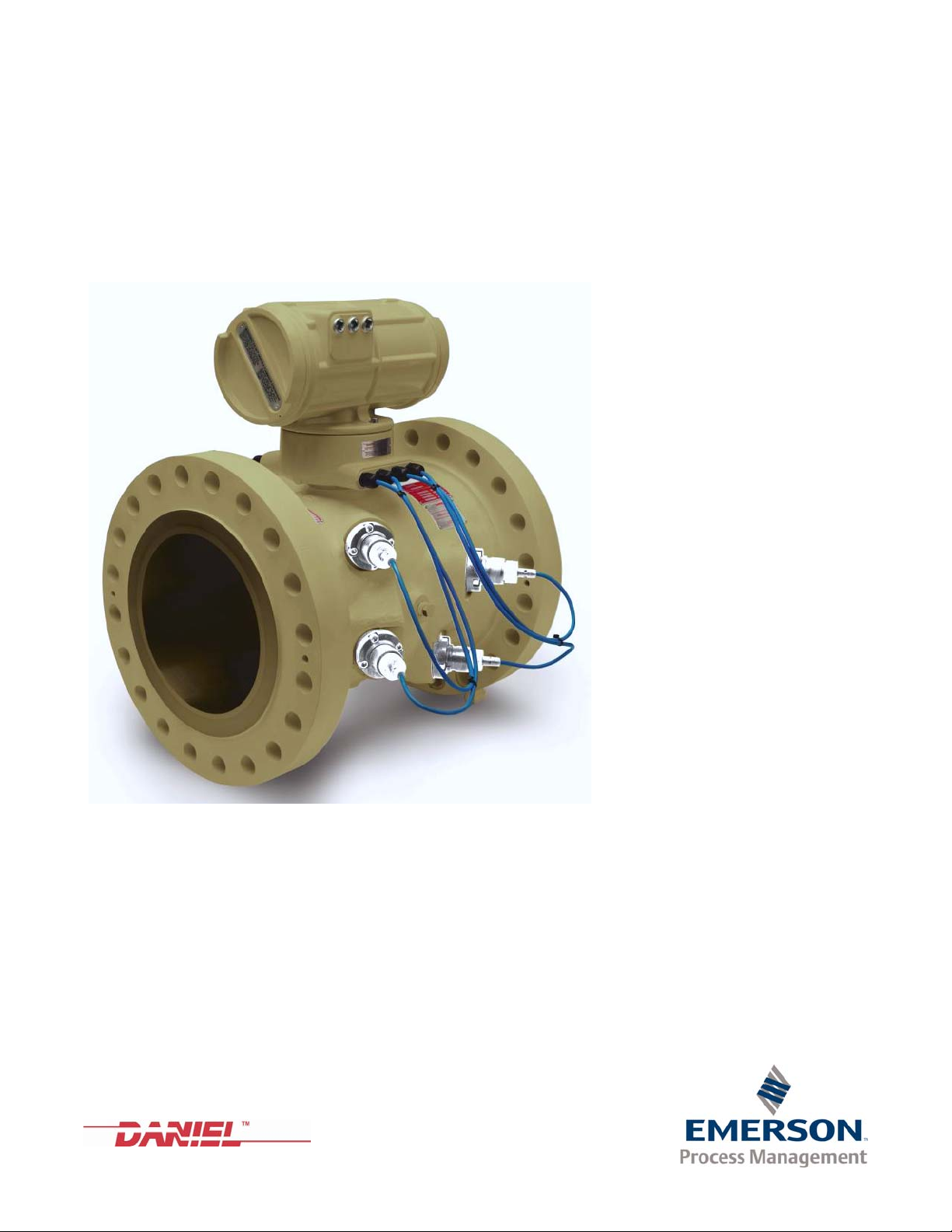
Supporting Multipath SeniorSonicTM - Model 3400, Multipath SeniorSonicTM - Model 3422
Single Path JuniorSonicTM - Model 3410, Dual Path JuniorSonicTM - Model 3420
Page 2

Page 3
Daniel customer service
Location Tel ephone num ber Fax number
North America/Latin America +1.713.467.6000 +1.713.827.4805
Daniel Customer Service +1.713.827.6413 +1.713.827.6312
USA (toll free) +1.888.356.9001 +1.713.827.3380
Asia Pacific (Republic of Singapore) +65.6777.8211 +65.6777.0947.0743
Europe (Stirling Scotland, UK) +44 (0)1786.433400 +44 (0)1786.433401
Middle East Africa (Dubai, UAE) +971 4 8118100 +971 4 8865465
E-mail
• Customer Service: tech.service@emersonprocess.com
• Customer Support: daniel.cst.support@emerson.com
• Asia-Pacific: danielap.support@emerson.com
• Europe: DanielEMA.CST@EmersonProcess.com
Return Material Authorization (RMA)
A Return Material Authorization (RMA) number must be obtained prior to returning any equipment for any reason.
Download the RMA form from the Support Services web page by selecting the link below.
www2.emersonprocess.com/EN-US/BRANDS/DANIEL/SUPPORT-SERVICES/Pages/Support-Services.aspx?
Page 4
Signal words and symbols
This is a safety alert symbol. It is used to alert you to potential physical injury hazards. Obey
all safety messages that follow this symbol to avoid possible injury or death.
Safety alert symbol
Danger indicates a hazardous situation which, if not avoided, will result in death or serious
injury.
Warning indicates a hazardous situation which, if not avoided, could result in death or serious
injury.
Caution indicates a hazardous situation which, if not avoided, could result in minor or
moderate injury.
Caution indicates a hazardous situation which, if not avoided, could result in minor or
moderate injury.
Pay special attention to the following signal words, safety alert symbols and statements:
Important
Important is a statement the user needs to know and consider.
Tip
Tip provides information or suggestions for improved efficiency or best results.
Note
Note is a “general by-the-way” content not essential to the main flow of information.
Page 5

Important safety instructions
Installing, operating or maintaining a Daniel product improperly could lead to serious injury or
death from explosion or exposure to dangerous substances. To reduce this risk:
• Comply with all information on the product, in this manual, and in any local and national
codes that apply to the product.
• Do not allow untrained personnel to work with this product.
• Use Daniel parts and work procedures specified in this manual.
Daniel Measurement and Control, Inc. (Daniel) designs, manufactures and tests products to
function within specific conditions. Because these products are sophisticated technical
instruments, it is important that the owner and operation personnel strictly adhere both to the
information printed on the product and to all instructions provided in this manual prior to
installation, operation, and maintenance.
Daniel also urges you to integrate this manual into your training and safety program.
BE SURE ALL PERSONNEL READ AND FOLLOW THE INSTRUCTIONS IN THIS MANUAL AND ALL
NOTICES AND PRODUCT WARNINGS.
Product owners (Purchasers):
• Use the correct product for the environment and pressures present. See technical data
or product specifications for limitations. If you are unsure, discuss your needs with your
Daniel representative.
• Inform and train all personnel in the proper installation, operation, and maintenance of
this product.
• To ensure safe and proper performance, only informed and trained personnel should
install, operate, repair and maintain this product.
• Verify that this is the correct instruction manual for your Daniel product. If this is not
the correct documentation, contact Daniel at 1-713-827-6314. You may also download
the correct manual from:
http://www.daniel.com
• Save this instruction manual for future reference.
• If you resell or transfer this product, it is your responsibility to forward this instruction
manual along with the product to the new owner or transferee.
• ALWAYS READ AND FOLLOW THE INSTALLATION, OPERATIONS, MAINTENANCE AND
TROUBLESHOOTING MANUALS AND ALL PRODUCT WARNINGS AND INSTRUCTIONS.
• Do not use this equipment for any purpose other than its intended service. This may
result in property damage and/or serious personal injury or death.
Page 6

Product Operation Personnel:
• To prevent personal injury, personnel must follow all instructions of this manual prior to
and during operation of the product.
• Follow all warnings, cautions, and notices marked on, and supplied with, this product.
• Verify that this is the correct instruction manual for your Daniel product. If this is not
the correct documentation, contact Daniel at 1-713-827-6314. You may also download
the correct manual from:
http://www.daniel.com
• Read and understand all instructions and operating procedures for this product.
• If you do not understand an instruction, or do not feel comfortable following the
instructions, contact your Daniel representative for clarification or assistance.
• Install this product as specified in the INSTALLATION section of this manual per
applicable local and national codes.
• Follow all instructions during the installation, operation, and maintenance of this
product.
• Connect the product to the appropriate pressure and electrical sources when and
where applicable.
• Ensure that all connections to pressure and electrical sources are secure prior to and
during equipment operation.
• Use only replacement parts specified by Daniel. Unauthorized parts and procedures can
affect this product's performance, safety, and invalidate the warranty. “Look-a-like”
substitutions may result in deadly fire, explosion, release of toxic substances or
improper operation.
• Save this instruction manual for future reference.
Page 7

Notice
THE CONTENTS OF THIS PUBLICATION ARE PRESENTED FOR INFORMATIONAL PURPOSES ONLY, AND WHILE
EVERY EFFORT HAS BEEN MADE TO ENSURE THEIR ACCURACY, THEY ARE NOT TO BE CONSTRUED AS
WARRANTIES OR GUARANTEES, EXPRESSED OR IMPLIED, REGARDING THE PRODUCTS OR SERVICES
DESCRIBED HEREIN OR THEIR USE OR APPLICABILITY. ALL SALES ARE GOVERNED BY DANIEL'S TERMS AND
CONDITIONS, WHICH ARE AVAILABLE UPON REQUEST. WE RESERVE THE RIGHT TO MODIFY OR IMPROVE THE
DESIGNS OR SPECIFICATIONS OF SUCH PRODUCTS AT ANY TIME.
DANIEL DOES NOT ASSUME RESPONSIBILITY FOR THE SELECTION, USE OR MAINTENANCE OF ANY PRODUCT.
RESPONSIBILITY FOR PROPER SELECTION, USE AND MAINTENANCE OF ANY DANIEL PRODUCT REMAINS
SOLELY WITH THE PURCHASER AND END-USER.
TO THE BEST OF DANIEL'S KNOWLEDGE THE INFORMATION HEREIN IS COMPLETE AND ACCURATE. DANIEL
MAKES NO WARRANTIES, EXPRESSED OR IMPLIED, INCLUDING THE IMPLIED WARRANTIES OF MERCHANTABILITY AND FITNESS FOR A PARTICULAR PURPOSE WITH RESPECT TO THIS MANUAL AND, IN NO EVENT, SHALL
DANIEL BE LIABLE FOR ANY INCIDENTAL, PUNITIVE, SPECIAL OR CONSEQUENTIAL DAMAGES INCLUDING, BUT
NOT LIMITED TO, LOSS OF PRODUCTION, LOSS OF PROFITS, LOSS OF REVENUE OR USE AND COSTS INCURRED
INCLUDING WITHOUT LIMITATION FOR CAPITAL, FUEL AND POWER, AND CLAIMS OF THIRD PARTIES.
PRODUCT NAMES USED HEREIN ARE FOR MANUFACTURER OR SUPPLIER IDENTIFICATION ONLY AND MAY BE
TRADEMARKS/REGISTERED TRADEMARKS OF THESE COMPANIES
Page 8

Warranty and Limitations
1. LIMITED WARRANTY: Subject to the limitations contained in Section 2 herein, Daniel Measurement &
Control, Inc. (“Daniel”) warrants that the licensed firmware embodied in the Goods will execute the
programming instructions provided by Daniel, and that the Goods manufactured by Daniel will be free from
defects in materials or workmanship under normal use and care and Services will be performed by trained
personnel using proper equipment and instrumentation for the particular Service provided. The foregoing
warranties will apply until the expiration of the applicable warranty period. Goods are warranted for twelve (12)
months from the date of initial installation or eighteen (18) months from the date of shipment by Daniel,
whichever period expires first. Consumables and Services are warranted for a period of 90 days from the date
of shipment or completion of the Services. Products purchased by Daniel from a third party for resale to Buyer
("Resale Products”) shall carry only the warranty extended by the original manufacturer. Buyer agrees that
Daniel has no liability for Resale Products beyond making a reasonable commercial effort to arrange for
procurement and shipping of the Resale Products. If Buyer discovers any warranty defects and notifies Daniel
thereof in writing during the applicable warranty period, Daniel shall, at its option, correct any errors that are
found by Daniel in the firmware or Services or repair or replace F.O.B. point of manufacture that portion of the
Goods or firmware found by Daniel to be defective, or refund the purchase price of the defective portion of the
Goods/Services. All replacements or repairs necessitated by inadequate maintenance, normal wear and usage,
unsuitable power sources or environmental conditions, accident, misuse, improper installation, modification,
repair, use of unauthorized replacement parts, storage or handling, or any other cause not the fault of Daniel
are not covered by this limited warranty, and shall be at Buyer's expense. Daniel shall not be obligated to pay
any costs or charges incurred by Buyer or any other party except as may be agreed upon in writing in advance
by Daniel. All costs of dismantling, reinstallation and freight and the time and expenses of Daniel's personnel
and representatives for site travel and diagnosis under this warranty clause shall be borne by Buyer unless
accepted in writing by Daniel. Goods repaired and parts replaced by Daniel during the warranty period shall be
in warranty for the remainder of the original warranty period or ninety (90) days, whichever is longer. This
limited warranty is the only warranty made by Daniel and can be amended only in a writing signed by Daniel.
THE WARRANTIES AND REMEDIES SET FORTH ABOVE ARE EXCLUSIVE. THERE ARE NO REPRESENTATIONS OR
WARRANTIES OF ANY KIND, EXPRESS OR IMPLIED, AS TO MERCHANTABILITY, FITNESS FOR PARTICULAR
PURPOSE OR ANY OTHER MATTER WITH RESPECT TO ANY OF THE GOODS OR SERVICES. Buyer acknowledges
and agrees that corrosion or erosion of materials is not covered by this warranty.
2. LIMITATION OF REMEDY AND LIABILITY
PERFORMANCE. THE REMEDIES OF BUYER SET FORTH IN THIS AGREEMENT ARE EXCLUSIVE. IN NO EVENT,
REGARDLESS OF THE FORM OF THE CLAIM OR CAUSE OF ACTION (WHETHER BASED IN CONTRACT,
INFRINGEMENT, NEGLIGENCE, STRICT LIABILITY, OTHER TORT OR OTHERWISE), SHALL DANIEL'S LIABILITY TO
BUYER AND/OR ITS CUSTOMERS EXCEED THE PRICE TO BUYER OF THE SPECIFIC GOODS MANUFACTURED OR
SERVICES PROVIDED BY DANIEL GIVING RISE TO THE CLAIM OR CAUSE OF ACTION. BUYER AGREES THAT IN NO
EVENT SHALL DANIEL'S LIABILITY TO BUYER AND/OR ITS CUSTOMERS EXTEND TO INCLUDE INCIDENTAL,
CONSEQUENTIAL OR PUNITIVE DAMAGES. THE TERM “CONSEQUENTIAL DAMAGES” SHALL INCLUDE, BUT NOT
BE LIMITED TO, LOSS OF ANTICIPATED PROFITS, REVENUE OR USE AND COSTS INCURRED INCLUDING
WITHOUT LIMITATION FOR CAPITAL, FUEL AND POWER, AND CLAIMS OF BUYER'S CUSTOMERS.
: DANIEL SHALL NOT BE LIABLE FOR DAMAGES CAUSED BY DELAY IN
Page 9

Reference, Installation, and Operations Manual Table of Contents
3-9000-743 Rev S June 2013
Contents
Preface
Daniel customer service
Signal words and symbols
Important safety instructions
Notice
Warranty and Limitations
Section 1: Introduction
1.1 Manual overview............................................................................................. 1
1.2 Definitions, acronyms, abbreviations................................................................ 2
1.3 What’s new .................................................................................................... 5
1.4 Daniel Ultrasonic Meter reference manuals ....................................................... 6
1.5 References ..................................................................................................... 7
Section 2: Product overview
2.1 Description .................................................................................................... 9
2.1.1 Advantages and Features ................................................................................... 10
2.1.2 Mechanical installation requirements................................................................. 11
2.2 Component parts.......................................................................................... 11
2.2.1 Daniel Mark III Ultrasonic Gas Flow Meters assembly .......................................... 12
2.2.2 Model 3400 meter body..................................................................................... 17
2.2.3 Model 3422 meter body..................................................................................... 18
2.2.4 Model 3410 meter body..................................................................................... 19
2.2.5 Model 3420 meter body..................................................................................... 20
2.2.6 Transducers and cabling..................................................................................... 21
2.3 General unit specifications ............................................................................ 22
2.3.1 The application .................................................................................................. 22
2.3.2 Available meter sizes.......................................................................................... 22
2.3.3 Pressure range ................................................................................................... 22
2.3.4 Flow range limits ................................................................................................ 23
2.3.5 Flange types....................................................................................................... 24
2.3.6 Gas temperature range ...................................................................................... 24
2.3.7 Repeatability...................................................................................................... 24
2.3.8 Accuracy limits................................................................................................... 24
Contents i
Page 10

Table of Contents Reference, Installation, and Operations Manual
June 2013 3-9000-743 Rev S
2.4 Electronic specifications ................................................................................25
2.4.1 Power specifications ...........................................................................................25
2.4.2 Temperature ......................................................................................................25
2.4.3 Inputs .................................................................................................................25
2.4.4 Outputs ..............................................................................................................25
2.4.5 Communications ................................................................................................25
2.5 Hardware features.........................................................................................26
2.5.1 Inputs .................................................................................................................26
2.5.2 Outputs ..............................................................................................................26
2.5.3 Status Indicators.................................................................................................29
2.6 Communications...........................................................................................35
2.7 Safety .......................................................................................................... 37
2.8 FCC Compliance............................................................................................38
Section 3: Installation
3.1 Installation instructions.................................................................................39
3.2 Daniel 3400 Series Ultrasonic Flow Meter lifting instructions and precautions....41
3.2.1 Use of appropriate safety engineered swivel hoist rings in meter end flanges ..... 43
3.2.2 Safety precautions using safety engineered swivel hoist rings.............................44
3.2.3 How to obtain safety engineered swivel hoist rings.............................................47
3.2.4 Using appropriately rated lifting slings on Daniel Ultrasonic Meters....................48
3.3 Mechanical installation..................................................................................51
3.3.1 Meter body installation.......................................................................................51
3.3.2 Mounting requirements for heated or cooled pipelines ......................................53
3.3.3 Accessing the Daniel 3400 Series Ultrasonic Flow Meter components ................53
3.3.4 Transducer cables/appropriate transducer .........................................................57
3.3.5 For systems using explosion-proof conduit.........................................................58
3.3.6 For systems that use flame-proof cable...............................................................59
3.4 Wiring and Connections ................................................................................ 60
3.5 Hardware Switch Settings ..............................................................................66
3.5.1 Communication settings ....................................................................................73
3.5.2 Frequency and Digital Output switch settings.....................................................79
3.5.3 Option Board analog inputs switch settings........................................................80
3.5.4 Series 100 Option Board analog output switch settings ......................................83
3.5.5 Series 100 Plus Option Board Analog Input switch settings .................................84
3.5.6 Series 100 Plus Option Board Analog Output switch settings ..............................86
3.5.7 DHCP server switch settings ...............................................................................88
3.5.8 Configuration protection switch settings............................................................88
3.6 Security seal installation ................................................................................ 88
3.6.1 End cap security seal installation.........................................................................89
3.6.2 Upper electronics housing to base unit security seal ...........................................90
3.6.3 Transducer assembly security seal installation ....................................................91
ii Contents
Page 11

Reference, Installation, and Operations Manual Table of Contents
3-9000-743 Rev S June 2013
Section 4: Optional features
4.1 Overview ..................................................................................................... 93
4.1.1 Managing optional feature keys ......................................................................... 93
4.1.2 Obtaining optional keys ..................................................................................... 94
4.1.3 Optional Ethernet key ........................................................................................ 94
4.1.4 Optional data log access key .............................................................................. 94
4.1.5 Optional GC interface key................................................................................... 94
4.1.6 Optional Aga10 key (sound velocity calculation) ................................................ 95
4.1.7 Key status........................................................................................................... 95
4.2 Key expiration warnings (firmware v1.6X and below) ....................................... 95
4.3 Grandfathered features (firmware v1.6X and below) ........................................ 95
4.4 Trial period (firmware v1.6X and below) ......................................................... 95
Section 5: Startup and meter configuration
5.1 Communications .......................................................................................... 97
5.2 Communications setup ............................................................................... 100
5.3 Communications setup wizard ..................................................................... 102
5.3.1 Advantages of Ethernet communication ..........................................................102
5.3.2 Initial Ethernet communications connection .................................................... 103
5.3.3 Ethernet communications connection ............................................................103
5.3.4 Ethernet initial connection steps ...................................................................... 104
5.4 Ethernet PC, HUB, or LAN connections.......................................................... 108
5.4.1 Direct connection from a Mark III to a PC.......................................................... 108
5.4.2 Connect a Mark III to a PC via an Ethernet hub .................................................. 108
5.4.3 Connect a Mark III Meter to a LAN via an Ethernet Hub ..................................... 109
5.5 Serial port connections using RS-232 serial cable .......................................... 109
5.5.1 RS-232 serial connection setup ........................................................................ 111
5.5.2 RS-485 serial connection setup ........................................................................ 113
5.5.3 Writing changes while connected to the meter ................................................ 118
5.6 Meter configuration setup wizard ................................................................. 119
5.6.1 Daniel MeterLink meter configuration overview...............................................120
5.6.2 Configuration protection ................................................................................. 122
5.6.3 Configuration checksum value and date........................................................... 123
5.6.4 Meter configuration using Daniel MeterLink..................................................... 123
5.6.5 Startup page .................................................................................................... 132
5.6.6 General Page.................................................................................................... 137
5.6.7 Frequency Outputs Page .................................................................................. 138
5.6.8 Current Outputs Page ......................................................................................140
Contents iii
Page 12

Table of Contents Reference, Installation, and Operations Manual
June 2013 3-9000-743 Rev S
5.6.9 HART® Output Page.........................................................................................144
5.6.10 Meter Digital outputs .......................................................................................146
5.6.11 Meter Corrections page ....................................................................................147
5.6.12 Temperature and Pressure page .......................................................................149
5.6.13 Gas Chromatograph Setup page.......................................................................154
5.6.14 AGA 8 Setup page.............................................................................................155
5.6.15 Continuous Flow Analysis page.........................................................................157
5.6.16 Set Baseline Wizard ..........................................................................................159
5.7 Process parameters and calibration configuration.......................................... 160
5.7.1 Update Time Wizard .........................................................................................160
5.7.2 Calculated results .............................................................................................162
5.7.3 Set calibration parameters................................................................................163
5.8 Saving the meter configuration .................................................................... 170
5.9 Maintenance logs and reports (Logs/Reports Menu) ....................................... 171
5.9.1 Log Format .......................................................................................................175
5.10 Trend maintenance logs (Logs/reports Menu) .............................................. 178
5.10.1 Meter Archive Logs (Logs/Reports Menu) .........................................................179
5.10.2 Compare Excel Meter Configurations (Logs/Reports Menu)..............................180
Section 6: Meter operation
6.1 Measurement .............................................................................................. 181
6.1.1 Terminology .....................................................................................................183
6.1.2 Signal processing..............................................................................................184
6.1.3 Batch cycle processing......................................................................................185
6.1.4 Acquisition mode .............................................................................................186
6.1.5 Chord gas and sound velocity measurements...................................................187
6.1.6 Average weighted sound velocity .....................................................................188
6.1.7 Average weighted gas flow velocity..................................................................190
6.1.8 Calibration........................................................................................................193
6.1.9 Volumetric flow rate .........................................................................................196
6.1.10 Volume.............................................................................................................201
6.1.11 Triggered Delta Volumes..................................................................................202
6.1.12 Energy rate and totals.......................................................................................203
6.1.13 Mass rate and totals .........................................................................................204
6.1.14 Seniorsonic flow characterizations....................................................................205
6.1.15 Flow-condition pressure and temperature........................................................206
6.1.16 Gas properties ..................................................................................................210
6.1.17 AGA8 compressibility calculations....................................................................215
iv Contents
Page 13

Reference, Installation, and Operations Manual Table of Contents
3-9000-743 Rev S June 2013
6.2 Frequency, digital, and analog outputs ......................................................... 215
6.2.1 Frequency outputs ........................................................................................... 215
6.2.2 Digital outputs ................................................................................................. 219
6.2.3 Analog (Current) output................................................................................... 221
6.3 Digital Input ............................................................................................... 226
6.4 Modbus communication .............................................................................. 227
6.4.1 Mapping data points to Modbus Registers........................................................ 227
6.4.2 Log record access............................................................................................. 228
6.5 Optional gas chromatograph interface ......................................................... 228
6.5.1 Hardware configuration ................................................................................... 228
6.5.2 Software configuration.....................................................................................229
6.5.3 Gas property data............................................................................................. 229
6.5.4 Data polling...................................................................................................... 230
6.5.5 GC data validity ................................................................................................ 231
6.5.6 GC alarm handling............................................................................................ 231
6.6 Archive logs ............................................................................................... 232
6.6.1 Daily log ........................................................................................................... 232
6.6.2 Hourly log ........................................................................................................ 238
6.6.3 Audit log .......................................................................................................... 241
6.6.4 Alarm log ......................................................................................................... 252
6.6.5 System log ....................................................................................................... 254
6.6.6 Reading log records.......................................................................................... 254
6.7 Viewing transducer waveforms .................................................................... 256
6.8 Upgrading the meter program ..................................................................... 256
6.8.1 Power disruption during firmware upgrade...................................................... 257
6.9 Self-tests and data reliability ....................................................................... 259
6.9.1 RAM integrity ................................................................................................... 259
6.9.2 Program integrity.............................................................................................259
6.9.3 Stored data integrity ........................................................................................ 259
6.9.4 Hardware watchdog......................................................................................... 259
6.9.5 Program execution integrity.............................................................................260
6.9.6 Log transfer integrity........................................................................................ 260
6.9.7 Data value limit checks..................................................................................... 260
6.9.8 Configuration dependency checks ................................................................... 260
Contents v
Page 14

Table of Contents Reference, Installation, and Operations Manual
June 2013 3-9000-743 Rev S
Section 7: Maintenance and troubleshooting
7.1 Field hydrostatic pressure testing procedures................................................ 261
7.2 T-Slot Transducer Removal and Installation Procedures .................................. 262
7.2.1 Removal with Extractor Tool .............................................................................262
7.2.2 Removal without Extractor Tool........................................................................265
7.2.3 Installing the transducers..................................................................................267
7.2.4 Replace the transformers..................................................................................270
7.2.5 Modifying the Calibration Parameters...............................................................271
7.3 Replacing the Mark III Electronics .................................................................272
7.4 Troubleshooting Communications ................................................................ 273
7.4.1 Unable to Connect Direct Serial or External Serial Modem ................................273
7.4.2 Unable to Connect to Meter..............................................................................273
7.4.3 Maintenance log files and trend files.................................................................274
7.4.4 Daniel MeterLink fails to connect or crashes using Windows® 2000 .................276
7.4.5 Windows® Hotfixes — Obtaining Hotfixes for Microsoft® Windows®...............277
7.4.6 Windows® 2000 SP-4 or a Windows® XP with security update ........................277
7.5 Troubleshooting Meter Status ...................................................................... 278
7.5.1 Meter Status Alarms .........................................................................................278
7.5.2 System Alarm ...................................................................................................279
7.5.3 Chord A to Chord D...........................................................................................280
7.5.4 Field I/O Alarm..................................................................................................280
7.5.5 Validity Alarm ...................................................................................................280
7.5.6 Comms Alarm...................................................................................................280
7.5.7 Check Status.....................................................................................................280
7.6 Maintenance logs and reports ...................................................................... 281
7.6.1 Collecting logs and viewing Excel reports..........................................................282
vi Contents
Page 15

Reference, Installation, and Operations Manual Table of Contents
3-9000-743 Rev S June 2013
Appendix A Conversion factors
A.1 Conversion factors per unit of measurement.................................................................. 293
Appendix B Miscellaneous equations
B.1 Miscellaneous conversion factors.................................................................................... 295
B.2 Chord “L” dimension calculation..................................................................................... 297
Appendix C Upgrading a Mark II to a Mark III
C.1 Meter electronics upgrade.............................................................................................. 299
C.2 What’s new In Mark III..................................................................................................... 299
C.3 Modbus Communication ................................................................................................ 302
C.3.1 Protocols .......................................................................................................... 302
C.3.2 Registers........................................................................................................... 302
C.3.3 Log Access ........................................................................................................ 302
C.4 Configuration conversion ............................................................................................... 303
C.4.1 Metrology - meter body and transducer calibration values................................ 303
C.4.2 Metrology - calibration equation parameters .................................................... 304
C.4.3 Gain .................................................................................................................. 307
C.4.4 Batch update period and stack size ................................................................... 307
C.4.5 Emission rate, stacked emission rate, and firing sequence ................................ 308
C.4.6 Chord failure threshold ..................................................................................... 308
C.4.7 Flow velocity estimation when a chord is failed ................................................. 308
C.4.8 Inactive chords.................................................................................................. 309
C.4.9 AlarmDef .......................................................................................................... 309
C.4.10 Frequency output configuration ..................................................................... 310
C.4.11 Flow pressure and temperature ...................................................................... 311
C.4.12 AGA8 method................................................................................................. 311
C.4.13 Minimum hold time ........................................................................................ 311
C.4.14 Log Format parameters................................................................................... 311
Appendix D Troubleshooting comm., mech., and elec.
D.1 Communications troubleshooting.................................................................................. 313
D.2 MARK III mechanical/electrical troubleshooting ............................................................. 315
Appendix E Meter setup and configuration worksheet
E.1 Meter setup and configuration worksheet....................................................................... 317
E.2 Meter to Flow Computer Communication Worksheet ..................................................... 322
Contents vii
Page 16

Table of Contents Reference, Installation, and Operations Manual
June 2013 3-9000-743 Rev S
Appendix F Flow rate summary charts
F.1 Flow Rate Summary Charts ..............................................................................................331
Appendix G Write-protected configuration parameters
G.1 Write-protected configuration........................................................................................ 335
Appendix H Open source licenses
H.1 Open source licenses ......................................................................................................345
H.1.1 GNU General Public License ..............................................................................346
H.1.2 BSD Open Source License..................................................................................359
H.1.3 M.I.T. License ....................................................................................................360
H.1.4 Mird License......................................................................................................361
Appendix I Engineering drawings
I.1 Ultrasonic Meter Drawings ...............................................................................................363
Appendix J Index
J.1 Manual Index....................................................................................................................365
viii Contents
Page 17

Reference, Installation, and Operations Manual List of Tables
3-9000-743 Rev S June 2013
List of Tables
Table 1-1 Gas Ultrasonic Meter acronyms, abbreviations and definitions ............................................. 2
Table 1-2 Daniel reference manuals ..................................................................................................... 6
Table 2-1 Transducer connection ports and number of transducers ................................................... 21
Table 2-2 Temperature ranges for transducers, mounts and holders.................................................. 24
Table 2-3 Voltage level and drive capability per logic level (TTL)......................................................... 27
Table 2-4 Configurations for open collector frequency outputs.......................................................... 28
Table 2-5 CPU Board General Status Indicators................................................................................... 31
Table 2-6 CPU Board Communication Status Indicators ..................................................................... 32
Table 2-7 Option Board General Status Indicators .............................................................................. 32
Table 2-8 Series 100 Plus Option Board General Status Indicators ...................................................... 33
Table 2-9 Option Board Communication Status Indicators................................................................. 33
Table 2-1 0 Series 100 Plus Option Board Communication Status Indicators ......................................... 34
Table 2-1 1 Supported Modbus Protocols ............................................................................................. 35
Table 3-1 Daniel hoist ring part numbers............................................................................................ 47
Table 3-2 Hoist Ring lookup table for Daniel Gas SeniorSonic Meters* ............................................... 47
Table 3-3 Hoist ring lookup table for Daniel Gas JuniorSonic Meters................................................... 48
Table 3-4 Piping recommendations uni-directional flow .................................................................... 51
Table 3-5 Piping recommendations bi-directional flow ...................................................................... 52
Table 3-6 Acquisition board wiring..................................................................................................... 57
Table 3-7 J7 Port B Wiring................................................................................................................... 60
Table 3-8 J2 Power ............................................................................................................................. 61
Table 3-9 J3 Chassis Ground ...............................................................................................................62
Table 3-1 0 J18 Digital Input.................................................................................................................. 62
Table 3-1 1 J11 Analog Output (AO1).................................................................................................... 62
Table 3-1 2 J12 Analog Input (AI1)......................................................................................................... 62
Table 3-1 3 J12 Analog Input 2 (AI2)...................................................................................................... 63
Table 3-1 4 J10 Analog Output Series 100 Plus Option Board (AO2) ...................................................... 63
Table 3-1 5 J11 Analog Output Series 100 Plus Option Board (AO1) ...................................................... 63
Table 3-1 6 J12 Analog Input Series 100 Plus Option Board (AI1) ........................................................... 63
Table 3-1 7 J12 Analog Input Series 100 Plus Option Board (AI2) ........................................................... 64
Table 3-1 8 J6 Port A.............................................................................................................................. 64
Table 3-1 9 J7 Port B.............................................................................................................................. 64
List of Tables ix
Page 18

List of Tables Reference, Installation, and Operations Manual
June 2013 3-9000-743 Rev S
Table 3-2 0 J16 Port C............................................................................................................................65
Table 3-2 1 J8 Ethernet Port................................................................................................................... 65
Table 3-2 2 DC Power Jumper Settings ..................................................................................................65
Table 3-2 3 Case Ground Jumper Settings..............................................................................................66
Table 3-2 4 Digital Input Connector.......................................................................................................66
Table 3-2 5 Port A driver settings...........................................................................................................74
Table 3-2 6 Port A RS-485 full duplex settings........................................................................................75
Table 3-2 7 Port A RS-485 half duplex settings.......................................................................................75
Table 3-2 8 Port B RS-232 driver settings...............................................................................................76
Table 3-2 9 Port B RS-485 full duplex .....................................................................................................77
Table 3-3 0 Port B RS-485 half duplex ....................................................................................................77
Table 3-3 1 Port C RS-232 settings.........................................................................................................78
Table 3-3 2 Port C RS-485 half duplex....................................................................................................78
Table 3-3 3 Option Board Analog In 1 temperature sin k settings...........................................................81
Table 3-3 4 Option Board Analog In 1 temperature source settings .......................................................81
Table 3-3 5 Option Board Analog In 2 pressure sink settings..................................................................82
Table 3-3 6 Option Board Analog In 2 pressure source settings..............................................................82
Table 3-3 7 Series 100 Option board Analog Out sink setting ................................................................83
Table 3-3 8 Series 100 Option board Analog Out source setting ............................................................83
Table 3-3 9 Series 100 Plus Option board Analog In 1 temperature sink setting.....................................84
Table 3-4 0 Series 100 Plus Option board Analog In 1 temperature source setting.................................85
Table 3-4 1 Series 100 Plus Option board Analog In 2 pressure sink setting ...........................................85
Table 3-4 2 Series 100 Plus Option board Analog In 2 pressure source setting .......................................86
Table 3-4 3 Series 100 Plus Option Board Analog Out 1 sink settings.....................................................86
Table 3-4 4 Series 100 Plus Option Board Analog Out 1 source settings.................................................87
Table 3-4 5 Series 100 Plus Option Board Analog Out 2 sink settings.....................................................87
Table 3-4 6 Series 100 Plus Option Board Analog Out 2 source settings.................................................87
Table 3-4 7 DHCP server settings........................................................................................................... 88
Table 3-4 8 CPU configuration protection switch...................................................................................88
Table 5-1 Daniel MeterLink setup wizards...........................................................................................98
Table 5-2 Supported Modbus Protocols............................................................................................101
Table 5-3 Data Points for Ethernet Port Configuration ......................................................................103
Table 5-4 Data Points for serial ports configuration ..........................................................................110
Table 5-5 Serial Port B RS-232 Configuration Switch Settings ........................................................... 112
x List of Tables
Page 19

Reference, Installation, and Operations Manual List of Tables
3-9000-743 Rev S June 2013
Table 5-6 Serial Port A RS-485 Full duplex configuration switch settings........................................... 114
Table 5-7 Serial Port A RS-485 half duplex configuration switch settings .......................................... 115
Table 5-8 Serial Port B RS-485 full duplex configuration switch settings ........................................... 116
Table 5-9 Serial Port B RS-485 half duplex configuration switch settings .......................................... 116
Table 5-1 0 Register reference help file ............................................................................................... 121
Table 5-1 1 Daniel MeterLink Field Setup Wizard................................................................................. 124
Table 5-1 2 Enabling Meter Corrections .............................................................................................. 135
Table 5-1 3 Enable Temperature/Pressure Meter Corrections Data Points, Source .............................. 136
Table 5-1 4 Data Points for Meter Real-Time Clock.............................................................................. 137
Table 5-1 5 Data Points for Analog (Current) Output Configuration .................................................... 141
Table 5-1 6 Live Temperature Inputs................................................................................................... 150
Table 5-1 7 Fixed Temperature Inputs................................................................................................. 151
Table 5-1 8 Live Pressure Inputs .......................................................................................................... 152
Table 5-1 9 Fixed Pressure Inputs ........................................................................................................ 153
Table 5-2 0 Field Setup Wizard - AGA 8 Setup...................................................................................... 156
Table 5-2 1 Data Points for Batch Cycle Processing, or Update Time Control....................................... 161
Table 5-2 2 Data Points for Dry Calibration.......................................................................................... 165
Table 5-2 3 Data Point for wet calibration method.............................................................................. 167
Table 5-2 4 Data Points for Piece-Wise linearization calibration........................................................... 168
Table 5-2 5 Data Points for Polynomial Wet Calibration ...................................................................... 169
Table 5-2 6 Ultrasonic Meter Archive Log Types .................................................................................. 180
Table 6-1 Actual meter update period.............................................................................................. 185
Table 6-2 AGA10 calculation status.................................................................................................. 189
Table 6-3 Volume Accumulation Data Points ................................................................................... 201
Table 6-4 Energy total data points.................................................................................................... 204
Table 6-5 Mass Total Data Points...................................................................................................... 205
Table 6-6 Flow-condition pressure and temperature data source..................................................... 207
Table 6-7 Fixed gas composition data points.................................................................................... 211
Table 6-8 GC-reported gas composition data points ........................................................................ 212
Table 6-9 “In-Use” gas composition data points............................................................................... 213
Table 6-1 0 C6+ breakdown to standard components by component ID............................................. 214
Table 6-1 1 FreqXB phase options ....................................................................................................... 216
Table 6-1 2 Data points for frequency outputs test ............................................................................. 218
Table 6-1 3 Data points for digital outputs test ................................................................................... 220
Table 6-1 4 Data points for output test mode ..................................................................................... 225
List of Tables xi
Page 20

List of Tables Reference, Installation, and Operations Manual
June 2013 3-9000-743 Rev S
Table 6-1 5 Gas Chromatograph Sim 2251 Registers...........................................................................228
Table 6-1 6 GC Communication status list...........................................................................................230
Table 6-1 7 GC-read gas property invalid conditions............................................................................231
Table 6-1 8 Daily log content...............................................................................................................233
Table 6-1 9 Hourly log content ............................................................................................................238
Table 6-2 0 Audit log content..............................................................................................................242
Table 6-2 1 Alarm log non-boolean data points monitored..................................................................252
Table 6-2 2 Alarm log boolean data points monitored......................................................................... 253
Table 7-1 Tools and supplies for disassembly and assembly..............................................................265
Table 7-2 Electronics serial numbers.................................................................................................272
Table 7-3 Chord alarms.....................................................................................................................280
Table 7-4 Maintenance log collection ...............................................................................................281
Table A-1
Conversion Factors per unit of measurement ........................................293
Table C-1 Mark II chord inactive conversion to Mark III data points ........................309
Table C-2 FreqXContent Conversion Mapping......................................................310
Table D-1 Mark III Mechanical/Electrical Troubleshooting ......................................315
Table E-1 Daniel 3400 Series Gas Ultrasonic Flow Meter setup
and configuration reference sheet ......................................................317
Table E-2 Meter to Flow Computer Communication Worksheet .............................322
Table H-1 Open source licenses .........................................................................345
xii List of Tables
Page 21

Reference, Installation, and Operations Manual List of Figures
3-9000-743 Rev S June 2013
List of Figures
Figure 1-2 Baseline viewer............................................................................................................... 1-5
Figure 2-2 Daniel Ultrasonic Gas Flow Meter Mark III Electronics ..................................................2-12
Figure 2-3 CPU Board (switch-side view) .......................................................................................2-13
Figure 2-4 CPU Board with I.S. Interface Board Mounted (
I.S. Barrier-side view) ...................................................................................................2-14
Figure 2-5 Series 100 Option board ...............................................................................................2-14
Figure 2-6 Series 100 Plus Option Board ........................................................................................2-15
Figure 2-7 Daniel Mark III Ultrasonic Gas Flow Meter Field Connection board ................................2-15
Figure 2-8 Mark III Acquisition Module...........................................................................................2-16
Figure 2-9 SeniorSonic Model 3400 meter body .........................................................................2-17
Figure 2-10 SeniorSonic Model 3422 meter body ............................................................................2-18
Figure 2-11 JuniorSonic Model 3410 meter body ............................................................................2-19
Figure 2-12 JuniorSonic Model 3420 meter body ............................................................................2-20
Figure 2-13 T-11 (left) Transducer and T-12 Transducer (right). ...................................................... 2-21
Figure 2-14 T-21 (left) and T-22 Transducer (right) ........................................................................2-21
Figure 2-15 Mark III CPU Board General Status LED Indicators.......................................................... 2-30
Figure 2-16 Mark III CPU Board General Status LED Indicators
(I.S. Interface-Side View) .............................................................................................. 2-30
Figure 2-17 Mark III CPU Board Communication Status Indicators
(I.S. Interface-Side View) .............................................................................................. 2-31
Figure 2-18 Mark III Option Board General Status LED Indicators .....................................................2-32
Figure 2-19 Series 100 Plus Option Board General Status LED Indicators......................................... 2-33
Figure 2-20 Mark III Option Board Communication Status LED Indicators .......................................2-33
Figure 2-21 Series 100 Plus Option Board Communication
Status LED Indicators ...................................................................................................2-34
Figure 2-22 Mark III Ultrasonic flow transmitter U.L. and IECEx certification tag .............................. 2-37
Figure 3-1 Meter end flange with tapped flat-counterbore hole for hoist ring ...............................3-43
Figure 3-2 Safety approved hoist ring and non-compliant eye bolt ...............................................3-44
Figure 3-3 Ninety degree angle between slings .............................................................................3-45
Figure 3-4 Incorrect sling attachment ...........................................................................................3-46
Figure 3-5 Correct sling attachment ........................................................................................... 3-49
Figure 3-6 Incorrect sling attachment ...........................................................................................3-50
Figure 3-7 Daniel Ultrasonic Gas meter body ................................................................................3-51
Figure 3-8 Daniel Mark III Ultrasonic Gas Flow Meter .....................................................................3-53
List of Figures xiii
Page 22

List of Figures Reference, Installation, and Operations Manual
June 2013 3-9000-743 Rev S
Figure 3-9 Upper electronics enclosure security seals ....................................................................3-54
Figure 3-10 Upper enclosure wiring card .........................................................................................3-55
Figure 3-11 Ground lug upper electronics enclosure .......................................................................3-55
Figure 3-12 Mark III base unit electronics ........................................................................................3-56
Figure 3-13 Transducer Ports and Cables Base Unit ........................................................................3-57
Figure 3-14 Field Connection Board Ethernet Connector Wiring .....................................................3-61
Figure 3-15 Port B Switch S1 Ethernet Settings ................................................................................3-61
Figure 3-16 Daniel 3400 Series Gas Ultrasonic Flow Meter
Wiring Switch Settings ................................................................................................3-66
Figure 3-17 Daniel 3400 Series Gas Ultrasonic Flow Meter
Wiring Connectors/Switches/LEDs................................................................................3-67
Figure 3-18 Option Board Wiring Connectors/Switches/LEDs ..........................................................3-68
Figure 3-19 Series 100 Plus Option Board Wiring Connectors/Switches/LEDs ..................................3-69
Figure 3-20 CPU Board Switches......................................................................................................3-70
Figure 3-21 Series 100 Option Board Switches.................................................................................3-71
Figure 3-22 Series 100 Plus Option Board Switches..........................................................................3-72
Figure 3-23 Field Connection board switches ..................................................................................3-73
Figure 3-24 Field Connection and CPU Board communication
configuration switch banks ..........................................................................................3-73
Figure 3-25 CPU Board Frequency and Digital Output
configuration switch banks .........................................................................................3-79
Figure 3-26 CPU Board Switch Banks S8 and S9 ...............................................................................3-80
Figure 3-27 Upper electronics end cap security seals .......................................................................3-89
Figure 3-28 Upper electronics housing to base unit security seal .....................................................3-90
Figure 3-29 Transducer housing, cable nut and security seal ...........................................................3-91
Figure 5-1 Program directory .....................................................................................................5-105
Figure 5-2 Ethernet connections parameters...............................................................................5-105
Figure 5-3 Meter connect ............................................................................................................5-106
Figure 5-4 Communications settings Ethernet port .....................................................................5-107
Figure 5-5 Writing Ethernet port communications settings .........................................................5-118
Figure 5-6 Write protected registers ...........................................................................................5-123
Figure 5-7 Field Setup Wizard - Startup Page (Series 100 Option Board) ......................................5-132
Figure 5-8 Field Setup Wizard - Startup Page (Series 100 Plus Option Board .............................5-133
Figure 5-9 Field Setup Wizard - General Page...............................................................................5-137
Figure 5-10 Field Setup Wizard - Meter Frequency Outputs Page ..................................................5-138
xiv List of Figures
Page 23

Reference, Installation, and Operations Manual List of Figures
3-9000-743 Rev S June 2013
Figure 5-11 Field Setup Wizard - Meter Current Outputs Page .......................................................5-140
Figure 5-12 Field Setup Wizard - HART Output Page
(Series 100 Plus Option Board) ..................................................................................5-144
Figure 5-13 Field Setup Wizard - Digital Outputs Page ..................................................................5-146
Figure 5-14 Field Setup Wizard - Meter Corrections page .............................................................. 5-147
Figure 5-15 Daniel MeterLink Field Setup Wizard -
Temperature and Pressure Page ................................................................................5-149
Figure 5-16 Field Setup Wizard - Gas Chromatograph Setup page.................................................5-154
Figure 5-17 Field Setup Wizard - AGA8 Setup page........................................................................5-155
Figure 5-18 Field Setup Wizard - Continuous Flow Analysis ...........................................................5-157
Figure 5-19 Meter Monitor - Baseline Viewer ................................................................................5-159
Figure 5-20 Daniel MeterLink Update Time Wizard ......................................................................5-160
Figure 5-21 Calibration - Meter Factors Page ................................................................................5-163
Figure 5-22 Maintenance logs and reports ...................................................................................5-171
Figure 5-23 Log file pathname .....................................................................................................5-172
Figure 5-24 Maintenance Logs and Reports - Data Collection ........................................................ 5-173
Figure 6-1 SeniorSonic measurement principle ...........................................................................6-181
Figure 6-2 Juniorsonic Measurement principle ............................................................................6-182
Figure 6-4 Update time, stack size, emission rate and filter .........................................................6-183
Figure 6-5 Meter Outputs Test Page with Option Board .............................................................6-223
Figure 6-6 Meter Outputs Test page with Expansion Board with HART® .....................................6-224
Figure 6-7 Program settings dialog FTP-only connection ............................................................6-257
Figure 6-8 Port A and B direct connection settings ......................................................................6-258
Figure 7-1 J-Mount Transducer Assembly ....................................................................................7-262
Figure 7-2 J-Mount Transducer Disassembly................................................................................7-263
Figure 7-3 M-Mount Transducer Disassembly.............................................................................. 7-263
Figure 7-4 M-Mount Transducer Disassembly .............................................................................7-264
Figure 7-5 T-21 and T-22 transducer assembly ...........................................................................7-266
Figure 7-6 Transducer holder, stalk and transducer assembly......................................................7-267
Figure 7-1 Transducer holder, stalk and transducer assembly......................................................7-267
Figure 7-7 M-mount cover and chordset with “V” arrowhead mark ............................................7-268
Figure 7-8 T-22 transducer assembly, holder, transformer, retainer, cable nut and chordset ...... 7-269
Figure 7-9 Daniel MeterLink Transducer Swap-out Wizard...........................................................7-271
Figure 7-10 Excel® Tools Menu ....................................................................................................7-275
Figure 7-11 Excel® Trusted Access Setting ...................................................................................7-276
List of Figures xv
Page 24

List of Figures Reference, Installation, and Operations Manual
June 2013 3-9000-743 Rev S
Figure 7-12 Meter Monitor Status Alarms .....................................................................................7-278
Figure 7-13 Meter Monitor Status Summary .................................................................................7-279
Figure 7-14 Maintenance Logs and Reports Dialog ........................................................................7-282
Figure 7-15 Log collection parameters ........................................................................................7-283
Figure 7-16 Excel custom view settings ........................................................................................7-283
Figure 7-17 Maintenance logs and reports start dialog .................................................................7-284
Figure 7-18 Speed of Sound dialog ..............................................................................................7-285
Figure 7-19 Log complete dialog ..................................................................................................7-285
Figure 7-20 Microsoft® Excel report view toolbar .........................................................................7-286
Figure 7-21 Microsoft® Excel charts view ......................................................................................7-287
Figure 7-22 Microsoft® Excel inspection report view ....................................................................7-288
Figure 7-23 Microsoft® Excel Speed of Sound View ......................................................................7-289
Figure 7-24 Microsoft® Excel Meter Config View ..........................................................................7-289
Figure 7-25 Microsoft® Excel Raw Data View ................................................................................7-290
xvi List of Figures
Page 25

Reference, Installation, and Operations Manual Section 1: Introduction
3-9000-743 Rev S June 2013
11
Section 1: Introduction
1.1 Manual overview
The Daniel Ultrasonic Gas Flow Meter Daniel Mark III Ultrasonic Gas Flow Meter Electronics
Reference, Installation, and Operations Manual (P/N 3-9000-743) provides descriptions and
explanations of the Daniel Multipath SeniorSonic
JuniorSonic
The Daniel 3400 Series Gas Ultrasonic Flow Meter was originally developed and tested by British
Gas. The unit was further developed by Daniel and features hardware and electronics designed
for easy use and minimum maintenance. All parts and assemblies have been tested prior to
shipment. Daniel holds an exclusive license from British Gas, obtained in 1986, to manufacture
and sell this product.
This manual consists of the following sections and appendices:
Sections:
TM
, Model 3410 and the Dual Path JuniorSonic
TM
Model 3400 and Model 3422, Single Path
TM
Model 3420.
Section 1- Introduction
Section 2 - Product Overview
Section 3 - Installation
Section 4 - Optional Features
Section 5 - Communications and Meter Configuration
Section 6 - Meter Operation
Section 7 - Maintenance
Appendices
Appendix A - Conversion Factors
Appendix B - Miscellaneous Equations
Appendix C - Upgrading from a Mark II to a Mark III
Appendix D - Communications, Mechanical, Electrical, Troubleshooting
Appendix E - Meter Setup and Configuration Worksheet
Appendix F - Flow Rate Summary
Appendix G - Write-Protected Configuration Parameters
Appendix H - Open Source Licenses
Appendix I - Engineering Drawings
Appendix J - Daniel Ultrasonic Gas Flow Meter Index
Manual overview 1
Page 26

Section 1: Introduction Reference, Installation, and Operations Manual
June 2013 3-9000-743 Rev S
1.2 Definitions, acronyms, abbreviations
The following terms, acronyms, and abbreviations are used in this document:
Table 1-1 Gas Ultrasonic Meter acronyms, abbreviations and definitions
Acronym or abbreviation Definition
° degree (angle)
o
C
o
F
ADC analog-to-digital converter
AGA American Gas Association
AI analog input
AMS™ Suite Asset Management Software
AO analog output
ASCII MODBUS A Modbus protocol message framing format in which ASCII characters are used to
boolean a type of data point that can only take on values of TRUE or FALSE (generally TRUE is
bps bits per second (baud rate)
Btu British thermal unit (heat unit)
cfh cubic feet per hour
cPoise centipoise (viscosity unit)
CPU central processing unit
CTS Clear-to-Send; the RS-232C handshaking signal input to a transmitter indicating that
DAC Digital-to-Analog Converter
Daniel CUI Daniel Customer Ultrasonic Interface
Daniel MeterLink Daniel software application for ultrasonic flow meters
DI digital input
DO digital output
Daniel MeterLink Daniel Customer User Interface
DHCP Dynamic Host Configuration Protocol
dm
ECC Error Correction Code
EEPROM Electrically-Erasable, Programmable Read-Only Memory
Flash non-volatile, programmable read-only memory
degrees celsius (temperature unit)
degrees fahrenheit (temperature unit)
delineate the beginning and end of the frame. ASCII stands for American Standard
Code for Information Interchange.
represented by a value of 1, FALSE is represented by a value of 0)
it is okay to transmit data – i.e., the corresponding receiver is ready to receive data.
Generally, the Request-to-Send (RTS) output from a receiver is input to the Clear-toSend (CTS) input of a transmitter.
decimeter (10
-1
meters, length unit)
2 Definitions, acronyms, abbreviations
Page 27

Reference, Installation, and Operations Manual Section 1: Introduction
3-9000-743 Rev S June 2013
Table 1-1 Gas Ultrasonic Meter acronyms, abbreviations and definitions
Acronym or abbreviation Definition
ft feet (length unit)
3
/d
ft
ft3/h
3
ft
/s
GC gas chromatograph
g-mol gram mole
HART®
hr hour (time unit)
Hz hertz (cycles per second, frequency unit)
I/O Input/Output
IS Intrinsically Safe
K kelvin (temperature unit)
3
kcal/m
kg kilogram (mass unit)
kg-mol kilogram mole
kg/d kilograms per day (mass rate)
kg/h kilograms per hour (mass rate)
kg/s kilograms per second (mass rate)
kHz
kJ
3
kJ/m
3
kwh/m
LAN Local Area Network
lbm pound mass
lbm-mol pound mass mole
lbm/d pounds (mass) per day (mass rate)
lbm/h pounds (mass) per hour (mass rate)
lbm/s pound (mass) per second (mass rate)
LED light-emitting diode
m meter (length unit)
3
m
/d
cubic feet per day (volumetric flow rate)
cubic feet per hour (volumetric flow rate)
cubic feet per second (volumetric flow rate)
Highway Addressable Remote Transducer
kilocalories per cubic meter (heating value)
kilohertz (103 cycles per second, frequency unit)
3
kilojoule (10
kilojoules per cubic meter (heating value)
kilowatt-hours per cubic meter (heating value)
cubic meters per day (volumetric flow rate)
joules, energy)
Definitions, acronyms, abbreviations 3
Page 28

Section 1: Introduction Reference, Installation, and Operations Manual
June 2013 3-9000-743 Rev S
Table 1-1 Gas Ultrasonic Meter acronyms, abbreviations and definitions
Acronym or abbreviation Definition
m3/h
3
m
/s
cubic meters per hour (volumetric flow rate)
cubic meters per second (volumetric flow rate)
mA milliamp (current unit)
microinch (
micron
μinch)
microinch (10
micrometer (10
-6
in)
-6
m)
MJ megajoule (energy)
MJ/d megajoules per day (energy rate)
MJ/m3 megajoules per cubic meter (heating value)
MJ/h megajoules per hour (energy rate)
MJ/s megajoules per second (energy rate)
MMBtu million British Thermal Units (energy)
MMBtu/d million Btu per day (energy rate)
MMBtu/h million Btu per hour (energy rate)
MMBtu/s million Btu per second (energy rate)
MMU Memory Management Unit
MPa
megapascal (equivalent to 10
6
Pascal) (pressure unit)
N/A not applicable
Nm3/h
normal cubic meters per hour
NOVRAM non-volatile random access memory
Pa Pascal, equivalent to 1 newton per square meter (pressure unit)
Pa⋅s Pascal Second (viscosity unit)
PC Personal Computer
PFC peripheral field connection (board)
P/N part number
ppm parts per million
PS power supply (board)
psi pounds per square inch (pressure unit)
psia pounds per square inch absolute (pressure unit)
psig pounds per square inch gage (pressure unit)
PWL Piece-Wise Linearization
rad radian (angle)
RAM Random Access Memory
4 Definitions, acronyms, abbreviations
Page 29
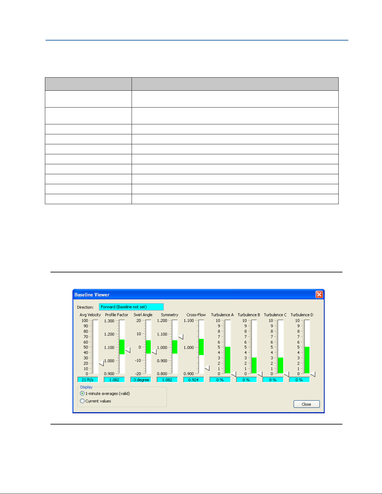
Reference, Installation, and Operations Manual Section 1: Introduction
3-9000-743 Rev S June 2013
Table 1-1 Gas Ultrasonic Meter acronyms, abbreviations and definitions
Acronym or abbreviation Definition
RTS Request-to-Send; the RS-232C handshaking signal output by a receiver when it is
ready to receive data
RTU MODBUS A Modbus protocol framing format in which elapsed time between received charac-
ters is used to separate messages. RTU stands for Remote Terminal Unit.
s second (time unit, metric)
Scfh seconds per cubic feet per hour
sec second (time unit, u.s. customary)
time_t seconds since Epoch (00:00:00 UTC Jan. 1, 1970) (time unit)
U.L. Underwriters Laboratories, Inc. - product safety testing and certification organization
USM Ultrasonic Gas Flow Meter
V volts (electric potential unit)
W watts (power unit)
1.3 What’s new
Daniel MeterLink
This version of Daniel MeterLink has robust features for monitoring the health status of Daniel
Ultrasonic Gas Flow Meters. Daniel MeterLink setup wizards guide you through the process of
configuring Continuous Flow Analysis parameters and setting Baselines. The Baseline Viewer
provides a graphical display of the meter’s flow characteristics.
Figure 1-2 Baseline viewer
What’s new 5
Page 30
Section 1: Introduction Reference, Installation, and Operations Manual
Daniel CUI version 4.21 is the final version that supports Daniel Mark II Gas Ultrasonic meters. If you are
communicating with a Daniel Ultrasonic Mark II Gas Flow Meter, you do not need to uninstall version 4.21 or
earlier versions of Daniel CUI before installing MeterLink. Version 4.21 and earlier versions of Daniel CUI should
not be run simultaneously with MeterLink.
June 2013 3-9000-743 Rev S
Continuous Flow Analysis
Continuous Flow Analysis provides operators and technicians with critical ultrasonic meter
diagnostic capabilities with meter status alerts when problems occur with:
• Abnormal profile
• Blockage
• Internal bore buildup
• Liquids present in the gas meter
• Reverse Flow
• Speed of Sound comparison error
1.4 Daniel Ultrasonic Meter reference manuals
Table 1-2 Daniel reference manuals
Part Number Title
P/N 3-9000-729
P/N 3-9000-740 Daniel Ultrasonic Gas Flow Meter Reference, Installation and Operations Manual (Applies to
P/N 3-9000-763 Daniel MeterLink Ultrasonic Meter Software Quick Start Manual
P/N 3-9000-743 Daniel Ultrasonic Gas Flow Meter Mark III Electronics Reference, Installation and Operations
P/N 3-9000-744 Ultrasonic Split Clamp Extractor Tool Operation Manual (Newer “J” &“K” Mounts)
P/N 3-9000-746 Daniel Ultrasonic Mark III Electronic Upgrade Kit Instructions
P/N 3-9000-749 Daniel Ultrasonic Mark III Option Board “A” Field Installation Procedure (Series 100 Options
P/N 3-9000-751 Daniel Transducer Installation and Upgrade Procedure
P/N 3-9000-754 HART Field Device Specification Guide: Daniel Gas Ultrasonic Meters
Ultrasonic Extractor Tool Operation Manual (Older “M” and “N”mounts)
Mark II meter)
Manual (This manual.)
Boards)
All technical manuals are available for download in Adobe® PDF format from the Daniel website:
http://www2.emersonprocess.com/EN-US/BRANDS/DANIEL/FLOW/Pages/Flow.aspx
6 Daniel Ultrasonic Meter reference manuals
Page 31

Reference, Installation, and Operations Manual Section 1: Introduction
3-9000-743 Rev S June 2013
1.5 References
[1]Gould Modbus Protocol Reference Guide, Rev. B, PI-MBUS-300
[2]Measurement of Fuel Gas By Turbine Meters, American Gas Association,
Transmission Measurement Committee Report No. 7, Second Revision, April
1996 (also referred to as AGA7)
[3]Compressibility Factors of Natural Gas and Other Related Hydrocarbon Gases,
American Gas Association, Transmission Measurement Committee Report No.
8, Second Edition, Second Printing, July 1994 (also referred to as AGA8)
[4]Manual of Petroleum Measurement Standards, Chapter 21 — Flow
Measurement Using Electronic Metering Systems, Section 1 — Electronic Gas
Measurement, American Gas Association and American Petroleum Institute,
First Edition, September 1993
References 7
Page 32

Section 1: Introduction Reference, Installation, and Operations Manual
June 2013 3-9000-743 Rev S
8 References
Page 33

Reference, Installation, and Operations Manual Section 2: Product overview
3-9000-743 Rev S June 2013
21
Section 2: Product overview
2.1 Description
The Daniel Ultrasonic Gas Flow Meter measures the flow of gas, especially natural gas, by
measuring the difference in signal transit time with and against the gas flow across one or more
measurement path(s). A signal transmitted in the flow direction travels faster than one
transmitted against the flow direction. Each measurement path is defined by a transducer pair
in which each transducer alternately acts as transmitter and receiver. The meter uses the transit
time measurements and transducer location information to calculate the mean gas velocity.
The Daniel Ultrasonic Gas Flow Meter offers bi-directional measurement capability (due to
meter symmetry) over a wide range of flow rates with no pressure loss. Accuracy, safety,
reliability, and ease-of-use are some of the many benefits of Daniel Ultrasonic Gas Flow Meters.
Computer simulations of various gas velocity profiles demonstrate that four measurement
paths provide an optimum solution for measuring asymmetric flow. The Daniel SeniorSonic
Meter (Models 3400 and 3422) utilizes four cross-bore, parallel-plane measurement paths to
offer a high degree of accuracy, repeatability, and superior low-flow capabilities without the
compromises associated with conventional technologies. These features make the
SeniorSonic
TM
Meter the best choice for custody transfer applications.
TM
TM
Daniel offers two JuniorSonic
Meter models (3410 and 3420) for applications that are
cost-sensitive and/or do not require custody-transfer levels of accuracy. Model 3410 utilizes one
measurement path; Model 3420 utilizes two measurement paths. Unlike the SeniorSonic
Meter designs, the JuniorSonic
Each transducer is angled 60° from horizontal (60
TM
design bounces the ultrasonic signal across the meter body.
o
included angle). The path is often referred to
TM
as a bounce-path (as the signal is bounced off the meter body) or a centerline path (as it goes
through the center-line of the meter body). The 3420 model’s two paths are configured at right
angles to one another in a “bulls-eye” arrangement. The bounce-path method simplifies
construction of the meter and makes the meter less susceptible to interference from pipeline
liquids.
TM
Since the JuniorSonic
Gas Flow Meter utilizes center-line paths, an additional piece of
information is needed to determine the average velocity of the moving gas (remember that not
all gas is moving at the same velocity). A “flow profile correction factor”, sometimes called the
Reynold's Number correction factor, is needed to correct the velocity measured along the
path(s) to the correct average for the cross sectional area. (see Section 5.6.11 and
Equation 6-18 for Reynolds correction information). This can be accomplished by either using a
fixed value or more accurately by measuring pressure and temperature, and then applying an
active correction to the measured transit times.
The dual-path configuration (3420 model) provides a more representative measurement of the
entire flow profile than the single-path configuration (3410 model).
The Daniel Ultrasonic Flow Gas Meter’s U.L. safety listing is accomplished through a
combination of an explosion-proof electronics enclosure, and intrinsically safe transducers. The
transducers and transducer leads are designed for maximum safety in a Class 1, Division 1 area
without need of further protection when installed in accordance with the field wiring diagram
(Daniel P/N DE-21056, see Appendix I).
Description 9
Page 34

Section 2: Product overview Reference, Installation, and Operations Manual
June 2013 3-9000-743 Rev S
2.1.1 Advantages and Features
Advantages and features of the Daniel Ultrasonic Flow Meter include:
• Proven long term stability
• Field proven reliability
• No line obstruction
• No pressure loss
• No moving parts
• Low maintenance
• Bi-directional measurement
• Extractable transducers
• Superior "dirty vs. clean" operation
• Fully digital electronics
• Extensive self diagnostics
• Immediate alarm reporting
• Continuous Flow Analysis
– Alarms
– Abnormal Profile
– Baselines - data configurable via Daniel MeterLink Baseline wizard
– Blockage
– Bore buildup
– Liquid detection
– SOS comparison with AGA10
– Signal and Noise Energy Amplitude
• Auto-detected ASCII/RTU Modbus communications protocol
• Low power consumption
• Sophisticated noise reduction
• One electronics set fits all models
• Internet-ready communications
• Optional Ethernet access
• On-board LED status indicators
• Optional gas chromatograph interface
• Optional analog pressure and temperature inputs
• Series 100 Plus Option Board - two additional independently configurable analog outputs
• Series 100 Plus Option Board enables the meter to easily communicate with other field
devices
• Communication via Emerson’s AMS™ Suite and 375 Field Communicator
10 Advantages and Features
Page 35

Reference, Installation, and Operations Manual Section 2: Product overview
3-9000-743 Rev S June 2013
• Detailed and Gross AGA8 calculations
• Optional AGA10 sound velocity calculation and comparison
• Optional API Chapter 21 compliant event and data logging
• Daniel MeterLink (powerful Windows-based interface software)
TM
Advantages and features of the SeniorSonic
• Range exceeds 50-1 within ±0.1% after flow calibration
• Unsurpassed measurement accuracy
• Superior low-flow capabilities
Advantages and features of the Daniel JuniorSonic
Model 3400 and Model 3422 include:
TM
Gas Flow Meter:
• Cost advantage over SeniorSonic
• Dual path redundancy (Model 3420)
• Large turn-down ratio
• Tol era nt of wet gas
The ultrasonic meter can use measured flow condition temperature and pressure values for use
in velocity profile-effect correction (for single-path and dual-path meters) and for volumetric
flow rate conversion to a user-specified base temperature/pressure condition.
TM
2.1.2 Mechanical installation requirements
Refer to Section 3.3.1 for mechanical installation requirements.
2.2 Component parts
The Daniel Ultrasonic Gas Flow Meters are available in various configurations to meet a broad
range of customer requirements. Each meter comes fully assembled from Daniel.
Mechanical installation requirements 11
Page 36

Section 2: Product overview Reference, Installation, and Operations Manual
Upper Explosion-Proof
Mark III Housing Assembly
Base Unit
Mark III
Electronics
Acquisition
Option
Boards
Board
CPU
Board
Assembly
Field
Termination
Board
I.S.
Interface
Board
June 2013 3-9000-743 Rev S
2.2.1 Daniel Mark III Ultrasonic Gas Flow Meters assembly
The Mark III electronics assembly consists of an upper explosion-proof housing and a lower
intrinsically-safe base unit assembly (see Figure 2-2).
Upper explosion-proof housing
• a Daniel Mark III Ultrasonic Gas Flow Meter CPU (Central Processing Unit) Board
• a Field Connection Board (for making electrical connections)
• a Daniel Mark III Ultrasonic Gas Flow Meter I.S. (Intrinsically-Safe) Interface Board
(permanently mounted on the CPU Board)
• Option Boards (Series 100 Option Board or Series 100 Plus Option Board).
Figure 2-2 Daniel Ultrasonic Gas Flow Meter Mark III Electronics
12 Daniel Mark III Ultrasonic Gas Flow Meters assembly
Page 37

Reference, Installation, and Operations Manual Section 2: Product overview
When the analog Series 100 Option Board or the Series 100 Plus Option Board is installed,
its corresponding I/O connectors on the Field Termination Board are automatically
activated for use.
3-9000-743 Rev S June 2013
Lower intrinsically-safe base unit assembly
All Mark III meter models utilize the same lower intrinsically-safe base unit assembly (see
Figure 2-2).
Base Unit
• encloses the intrinsically-safe Acquisition Board that interfaces with transducers
• connects the main electronics assembly to the meter body
Figure 2-3 CPU Board (switch-side view)
Daniel Mark III Ultrasonic Gas Flow Meters assembly 13
Page 38

Section 2: Product overview Reference, Installation, and Operations Manual
CPU
Board
Connection to
Acquisition
Board
I.S. Interface
Board (permanently
mounted)
June 2013 3-9000-743 Rev S
Figure 2-4 CPU Board with I.S. Interface Board Mounted (I.S. Barrier-side view)
Figure 2-5 Series 100 Option board
14 Daniel Mark III Ultrasonic Gas Flow Meters assembly
Page 39

Reference, Installation, and Operations Manual Section 2: Product overview
3-9000-743 Rev S June 2013
Figure 2-6 Series 100 Plus Option Board
Figure 2-7 Daniel Mark III Ultrasonic Gas Flow Meter Field Connection board
Daniel Mark III Ultrasonic Gas Flow Meters assembly 15
Page 40

Section 2: Product overview Reference, Installation, and Operations Manual
Connections
to Transducers
Connection
to CPU Board
June 2013 3-9000-743 Rev S
Figure 2-8 Mark III Acquisition Module
16 Daniel Mark III Ultrasonic Gas Flow Meters assembly
Page 41

Reference, Installation, and Operations Manual Section 2: Product overview
3-9000-743 Rev S June 2013
2.2.2 Model 3400 meter body
See Figure 2-9 SeniorSonic
• Serves as the core of the unit
• Features the multipath, acoustic-signal scheme for measuring transit time on four parallel
paths for calculating gas flow under asymmetric and swirl conditions
• Has port connections for mounting the unit's ultrasonic transducers
• Path location
TM
- located at ± 0.309 and ± 0.809
- Two paths are located at 0.309-R from the center of the meter and two are
located 0.809-R from the wall
Figure 2-9 SeniorSonic
TM
Model 3400 meter body
Model 3400 meter body 17
Page 42

Section 2: Product overview Reference, Installation, and Operations Manual
June 2013 3-9000-743 Rev S
2.2.3 Model 3422 meter body
See Figure 2-10 SeniorSonic
TM
• Serves as the core of the unit
• Features an acoustic-signal scheme for measuring transit time on four equal-length
parallel paths for calculating gas flow under asymmetric and swirl conditions
• Has port connections for mounting the unit's ultrasonic transducers
• Path location:
all are located at ± 0.5-R from the center of the meter
TM
Figure 2-10 SeniorSonic
Model 3422 meter body
18 Model 3422 meter body
Page 43
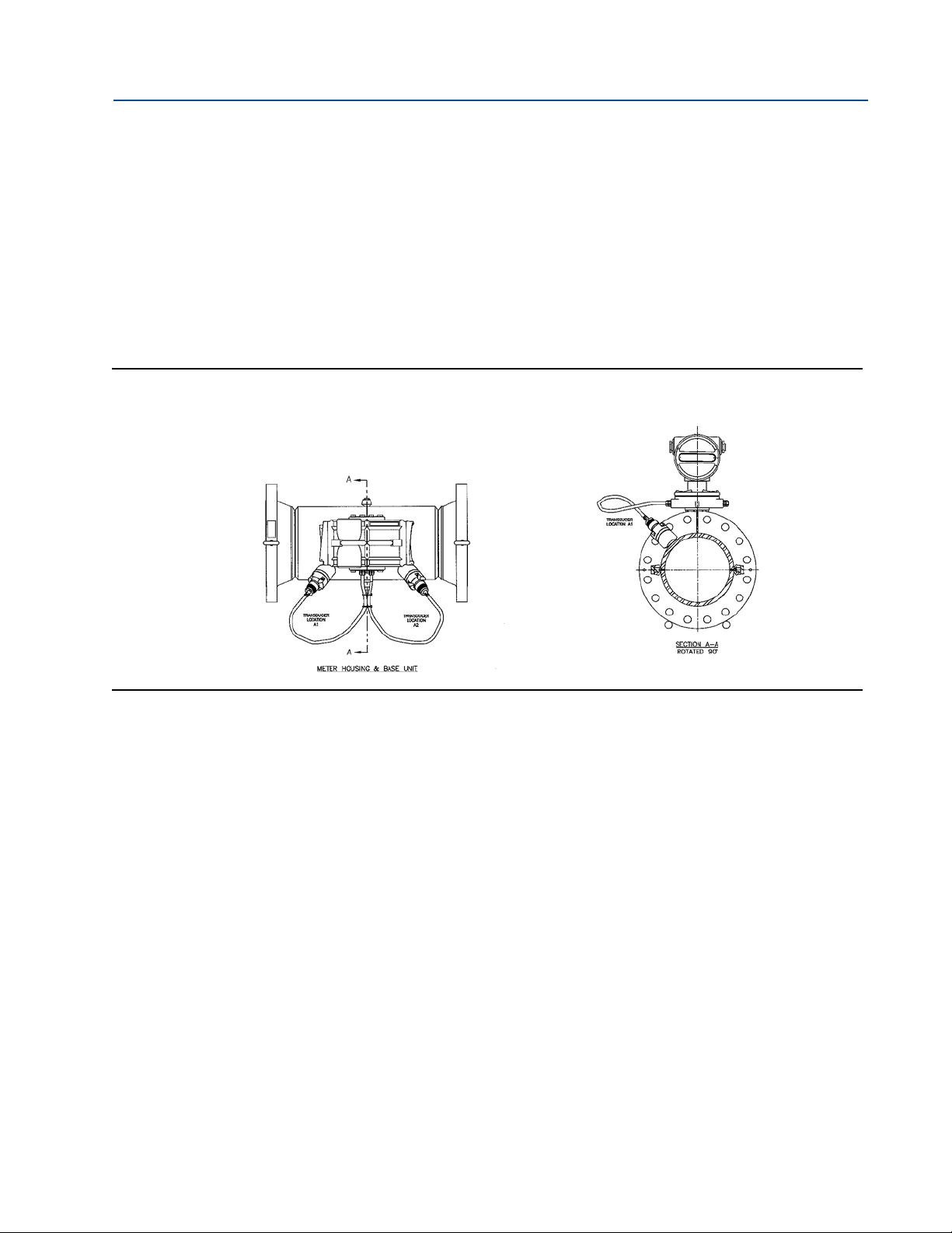
Reference, Installation, and Operations Manual Section 2: Product overview
3-9000-743 Rev S June 2013
2.2.4 Model 3410 meter body
See Figure 2-11 JuniorSonicTM
• Serves as the core of the unit
• Features an acoustic-signal scheme for measuring transit time on one bounce path for
calculating gas flow
• Has port connections for mounting the unit's ultrasonic transducers
• Transducer location allows for natural drainage under wet gas conditions
TM
Figure 2-11 JuniorSonic
Model 3410 meter body
Model 3410 meter body 19
Page 44

Section 2: Product overview Reference, Installation, and Operations Manual
June 2013 3-9000-743 Rev S
2.2.5 Model 3420 meter body
See Figure 2-12 JuniorSonicTM
• Serves as the core of the unit
• Features:
o
– two center paths (90
– acoustic-signal scheme measuring travel time for calculating gas flow
• Has port connections for mounting the unit's ultrasonic transducers
• Transducer location allows for natural drainage under wet gas conditions
Figure 2-12 JuniorSonic
TM
apart)
Model 3420 meter body
20 Model 3420 meter body
Page 45

Reference, Installation, and Operations Manual Section 2: Product overview
3-9000-743 Rev S June 2013
2.2.6 Transducers and cabling
The standard transducers are designated as T-11, T-12, T-21 and T-22. The T-11 is a direc t
replacement for the older T-2 transducers. The T-12 and T-22 is a small diameter version of the
T-11 and the T-21, suitable for small meters such as a 4-inch meter, as well as the 8-inch, 10-inch
o
and 12-inch 60
SeniorSonic
Figure 2-13 T-11 (left) Transducer and T-12 Transducer (right).
TM
meters
Figure 2-14 T-21 (left) and T-22 Transducer (right)
Table 2-1 Transducer connection ports and number of transducers
Model Meter Ports Tra nsdu ce rs
3400
3410
3420
3422
SeniorSonic
JuniorSonic
JuniorSonic
SeniorSonic
TM
(Four Path)
TM
(Single-Path)
TM
(Dual-Path)
TM
(with half-radius chords)
88
22
44
88
Transducers and cabling 21
Page 46

Section 2: Product overview Reference, Installation, and Operations Manual
Consult Daniel Measurement Services for applications less than 150 psig.
Daniel should be consulted for larger pipe size availability.
Daniel should be consulted for lower or higher pressure applications.
June 2013 3-9000-743 Rev S
2.3 General unit specifications
The following section describes general specifications for all Daniel Mark III Ultrasonic Gas Flow
Meters.
2.3.1 The application
The application is for high-pressure gases. Minimum operating pressure is typically 10 bar
(150 psi).
2.3.2 Available meter sizes
Both SeniorSonic
from 100 mm to 900 mm (4 inches to 36 inches).
TM
and JuniorSonic
2.3.3 Pressure range
In accordance with ANSI B16.5, the meter housings are available in ANSI pressure classes 300,
600, 900 and 1500.
TM
meters are available in nominal meter body pipe sizes
22 General unit specifications
Page 47

Reference, Installation, and Operations Manual Section 2: Product overview
Daniel should be consulted before establishing the actual meter capacity for a particular
application.
44
37 =
37=
701 1
1 701 701
701 1 1
=
Q
refQf
P
f
P
ref
T
ref
T
f
Z
ref
Z
f
3-9000-743 Rev S June 2013
2.3.4 Flow range limits
The reference condition flow range limits for SeniorSonic
900 mm) are listed in the appendix tables (see Appendix F).
The meter capacity at reference (base) conditions of pressure and temperature may be
calculated as shown in Equation 2-1.
Equation 2-1 Meter capacity - reference conditions of pressure and temperature
where
=
flow rate at reference conditions (Nm3/h; Scfh)
TM
Meters (pipe sizes from 100 mm to
=
flow rate at flowing conditions (m3/h; cfh)
= absolute pressure at flowing conditions (Pa; psia)
= absolute pressure at reference conditions (Pa; psia)
= absolute temperature at reference conditions (K; R)
= absolute temperature at flowing conditions (K; R)
= compressibility of gas at reference conditions
(dimensionless)
= compressibility of gas at flowing conditions
(dimensionless)
Flow range limits 23
Page 48

Section 2: Product overview Reference, Installation, and Operations Manual
June 2013 3-9000-743 Rev S
2.3.5 Flange types
The meter body is available with raised face or ring-type joint flange.
2.3.6 Gas temperature range
The gas temperature ranges for the standard T-11, T-12, T-21 and T-22 transducers are as show
in Ta bl e 2 -2 .
Table 2-2 Temperature ranges for transducers, mounts and holders
Tran sducer t y p e Temperature range Mount and holder type
T-11 -20 °C to +100 °C (-4 °F to 212 °F) Standard mounts/Holders, NBR O-ring
Inconel mounts/316L Holders, NBR O-ring
Inconel Mounts/Inconel Holders/FKM O-ring
T-12 -20 °C to +100 °C (-4 °F to 212 °F) Standard mounts/Holders, NBR O-ring
Inconel mounts/316L Holders, NBR O-ring
Inconel Mounts/Inconel Holders/FKM O-ring
1
T-2 1
2
T-2 2
1. T-21 transducers use W-01 transformers
2. T-22 transducers use W-02 transformers
-20 °C to +100 °C (-4 °F to 212 °F) Standard mounts/Holders, NBR O-ring
-50 °C to +100 °C (-58°F to 212 °F) Standard mounts/Holders, NBR O-ring
Temperatures below -20 °C may damage the transducers. In no-flow conditions for extended
lengths of time or during meter storage, you should remove all transducer pairs if the
temperature range is expected to exceed these limits.
Consult Daniel for higher temperature applications.
2.3.7 Repeatability
Repeatability precision is ±0.2% of reading in the specified velocity range for SeniorSonic
Meters.
2.3.8 Accuracy limits
SeniorSonic
TM
accuracy limits typically are:
Inconel mounts/316L Holders, NBR O-ring
Inconel Mounts/Inconel Holders/FKM O-ring
Inconel mounts/316L Holders, NBR O-ring
Inconel Mounts/Inconel Holders/FKM O-ring
TM
• AGA 9 compliant
• ± 1% without a flow calibration (10” and smaller)
± 0.7% without a flow calibration (for 12” and larger)
• ± 0.1% with a flow calibration
• JuniorSonic
– ± 2% without a flow calibration
24 Flange types
TM
accuracy limits typically are:
Page 49

Reference, Installation, and Operations Manual Section 2: Product overview
3-9000-743 Rev S June 2013
2.4 Electronic specifications
This section discusses the specifications for Daniel Mark III Ultrasonic Gas Flow Meters.
2.4.1 Power specifications
• 24 VDC nominal, range: 10.4 VDC to 36 VDC
• total power consumption less than 8 W
2.4.2 Temperature
Flameproof enclosure and Intrinsically safe base unit refer to Ta bl e 2 -2 for temperature ranges.
Important
The process temperature must not exceed the operating temperature range of the transducers.
2.4.3 Inputs
• one general-purpose digital input
• optional analog inputs, one each for pressure and temperature (requires the Option
Board)
2.4.4 Outputs
• two frequency output pairs (4 total)
• four digital outputs
• one optional analog output (requires the Option Board)
• two optional analog outputs (requires the Series 100 Plus Option Board)
2.4.5 Communications
• two serial ports (RS-232/RS-485 Full Duplex/RS-485 Half Duplex) with manually switched
RS-485 terminations
• optional third serial port (RS-232/RS-485 Half Duplex) with manually switched RS-485
terminations (requires the Option Board or Series 100 Plus Option Board)
• one optional Ethernet port (10 BaseT)
• The optional third serial port can be used as a Modbus master to communicate with a
Daniel Gas Chromatograph (GC) in Sim 2251 mode.
Electronic specifications 25
Page 50

Section 2: Product overview Reference, Installation, and Operations Manual
June 2013 3-9000-743 Rev S
2.5 Hardware features
2.5.1 Inputs
Digital input
The meter provides a single general-purpose digital input. The input signal polarity is selectable
via a configuration data point and its (polarity-configured) value is readable via another data
point.
Pressure and temperature analog inputs
The meter provides two analog inputs (AIs) via the Option Board or the Series 100 Plus Option
Board - one for temperature (AI1) and one for pressure (AI2). Each analog input is expected to
be a 4-20mA signal.
The analog-to-digital conversion accuracy is within ±0.05% of full scale over the operating
temperature range.
2.5.2 Outputs
frequency Outputs
The Daniel Mark III Ultrasonic Gas Flow Meter provides two pairs of frequency outputs where
each pair is individually configurable. The first pair is comprised of FO1A and FO1B; the second
pair is comprised of FO2A and FO2B. The information represented by each frequency pair is
software selectable (with selections such as flow volume, gas velocity, sound velocity, energy
rate, or mass rate - see Section 5.6.7). The frequency output range for each pair is individually
software selectable as either 0-1000 Hz or 0-5000 Hz (with an overrange of 50%).
The worst case frequency output granularity is 1 Hz at 5000 Hz. When a frequency is configured
to represent volume, the volume accuracy is within ±0.01%.
The meter provides two pairs of configurable frequency outputs (FO1A, FO1B, FO2A, and
FO2B), four configurable digital outputs (DO1A, DO1B, DO2A, and DO2B), and an optional
analog output (AO1).
The frequency and digital outputs are divided into two groups as follows:
• Group 1:FO1A, FO1B, DO1A, DO1B
• Group 2:FO2A, FO2B, DO2A, DO2B
26 Hardware features
Page 51

Reference, Installation, and Operations Manual Section 2: Product overview
If outputs from both groups are to be connected to the same device, then the two group
grounds must be connected together, either at the Daniel Mark III Ultrasonic Gas Flow Meter
Field Connection Board or at the flow computer, whichever is more convenient.
3-9000-743 Rev S June 2013
Each group has a separate ground (i.e., Group1Gnd and Group 2 Gnd) and there is up to 50 V
isolation between the two groups. Thus, all outputs within a group share a common ground.
This allows each output group to be connected to a different flow computer. Daniel should be
consulted before establishing the actual meter capacity for a particular application.
All outputs are opto-isolated from the CPU Board (with a withstand of at least 500 Volt rms
dielectric).
Each output is individually configurable as either internally powered (TTL) or externally powered
(“open collector” e.g. O.C.). An output signal configured as “internally powered” is powered
from an internal isolated 5 VDC bus and has voltage levels and drive capability as shown in
Ta bl e 2 -3 .
Table 2-3 Voltage level and drive capability per logic level (TTL)
Logic Value Voltage Level Drive Capability
0 < 0.7 V maximum sinking current:10 mA
1 > 3.5 V maximum sourcing current:10 mA
An output signal configured as “open collector” (externally powered) must not exceed 60 VDC
and must not be allowed to sink more than 50 mA.
Cable length TTL mode
The maximum cable length is 2000 feet when the “TTL” mode is selected.
Outputs 27
Page 52

Section 2: Product overview Reference, Installation, and Operations Manual
ΩΩΩ
June 2013 3-9000-743 Rev S
Cable length open collector mode
For the “open collector” mode, the maximum cable length depends on the cable parameters,
pull-up resistance used, the maximum frequency to output, and frequency input parameters
being driven. The following table provides estimated cable lengths for different pull-up resistor
values and different Max Frequency settings in the meter using the following cable parameters.
The table also provides an estimated cable voltage drop which indicates how much voltage will
be across the cabling and effectively indicates to what voltage level the frequency input can be
pulled down to by the frequency output.
If the voltage drop is higher than the voltage required for the frequency input to see a LOW
state, then the configuration will most likely not work for your system. Performance of
Frequency Outputs will vary from this table with setup and frequency input being driven.
Table 2-4 Configurations for open collector frequency outputs
Cable
Length (2 Conductors) Capacitance Resistance Resistance Frequency Current (2 Conductors)
(x1000ft) nF (Hz) (A) VDC
0.5 16.8 10.00 1000 1016.8 5000 0.024 0.397
1 33.6 20.00 1000 1033.6 1000 0.023 0.780
2 67.2 40.00 1000 1067.2 1000 0.022 1.511
4 134.4 80.00 1000 1134.4 1000 0.021 2.843
0.5 16.8 10.00 500 516.8 5000 0.046 0.780
1 33.6 20.00 500 533.6 5000 0.045 1.511
1.7 57.12 34.00 500 557.12 5000 0.043 2.461
6.5 218.4 130.00 500 718.4 1000 0.033 7.296
Cable
Resistance
Cable Pull-up Total Maximum Sink
Cable Voltage
Drop
The 22 AWG wire characteristics are as follows:
• Capacitance = 20 pF/ft or 20 nF/1000 ft (between two wires)
• Resistance = 0.0168 Ohms/ft or 16.8 Ohms/1000 ft
• Pull-up voltage is 24 VDC
Digital outputs
The Daniel Mark III Ultrasonic Gas Flow Meter provides four digital outputs arranged in two pairs.
The first pair is comprised of DO1A and DO1B; the second pair is comprised of DO2A and DO2B.
Each digital output is individually software configurable for content and polarity (see
Section 5.6.10).
The maximum digital output cable length is 2000 feet.
28 Outputs
Page 53

Reference, Installation, and Operations Manual Section 2: Product overview
AI-1 and AI-2 are electronically isolated, independently configurable to operate in either sink
or source mode and an additional 150 Ohms Loop impedance. Can be connected to HART®
enabled transmitter.
3-9000-743 Rev S June 2013
Analog output(s)
A 4-20 mA analog output is provided via the Option Board. The analog output is software
configurable (similar to the frequency outputs) and can represent volumetric flow rate, gas
velocity, sound velocity, energy rate, or mass rate (see Figure 5.6.8).
Two 4-20 mA independently configurable analog outputs are available with the Series 100 Plus
Board installed.
The analog output zero scale offset error is within ±0.1% of full scale and gain error is within
±0.2% of full scale. The total output drift is within ±50 ppm of full scale per °C.
2.5.3 Status Indicators
The meter has several light-emitting diode (LED) status indicators on both the CPU Board and
Option Board for general status and communication status indication.
CPU Board General Status Indicators
The meter indicates the status of the metrology mode and the status of the data transfer from
the Acquisition Board to the CPU Board via LEDs located on the CPU Board (see Figure 2-13 and
Figure 2-16). Additional LEDs are included for future use. Ta b l e 2 - 5 summarizes the CPU Board
general status indicators.
Status Indicators 29
Page 54

Section 2: Product overview Reference, Installation, and Operations Manual
General Status LED Indicators
1
2
3
4
5
6
2
June 2013 3-9000-743 Rev S
Figure 2-15 Mark III CPU Board General Status LED Indicators
Figure 2-16 Mark III CPU Board General Status LED Indicators (I.S. Interface-Side View)
30 Status Indicators
Page 55

Reference, Installation, and Operations Manual Section 2: Product overview
LED 5 is the surest indicator of the basic system health. If LED 5 is blinking, it indicates a good
connection to the Acquisition Board and the overall operation of all firmware. LED 5 should blink even if
no transducers are connected to the Acquisition Board.
Communication Status LED Indicators
3-9000-743 Rev S June 2013
Table 2-5 CPU Board General Status Indicators
Label Description Color Indicator
LED 1 Color indicates the metrology mode Red - Acquisition Mode
Green - Measurement Mode
LED 2 Unassigned Red
LED 3 Unassigned Yellow
LED 4 Unassigned Green
LED 5 Indicates when the CPU Board is receiving
data from the
Acquisition Board
LED 6 Unassigned Green
Green - Blinking when data is being received
CPU Board Communication Status Indicators
LED status indicators are provided on the CPU Board to indicate the serial Port A and B receive
and transmit statuses and to indicate the Ethernet port connection status (see Figure 2-17).
These indicators are summarized in Ta bl e 2 -6 .
Figure 2-17 Mark III CPU Board Communication Status Indicators (I.S. Interface-Side View)
Status Indicators 31
Page 56

Section 2: Product overview Reference, Installation, and Operations Manual
June 2013 3-9000-743 Rev S
Table 2-6 CPU Board Communication Status Indicators
Label Description Color
PORT A RX Port A receive status Green LED On
PORT A TX Port A transmit status Green LED On
PORT B RX Port B receive status Green LED On
PORT B TX Port B transmit Green LED On
LINK Ethernet port connection status Green LED On
Activity
Indication
Blinking
Blinking
Blinking
Blinking
Solid
Option Board General Status Indicators
As shown in Figure 2-18, the Option Board provides three general status indicators as
summarized in Tab l e 2 - 7 .
Figure 2-18 Mark III Option Board General Status LED Indicators
No Activity
Indication
LED Off
LED Off
LED Off
LED Off
LED Off
Table 2-7 Option Board General Status Indicators
Label Description Color Indicator
24V CURR LIMIT Indicates that the 24V source is current limited (approx. 70 mA) Red
+24V Indicates that the 24V supply is OK Green
3.3V Indicates that the 3.3V supply is OK Green
32 Status Indicators
Page 57

Reference, Installation, and Operations Manual Section 2: Product overview
3-9000-743 Rev S June 2013
Series 100 Plus Option Board General Status Indicators
As shown in Figure 2-19, the Series 100 Plus Option Board provides nine general status
indicators as summarized in Ta bl e 2 - 8.
Figure 2-19 Series 100 Plus Option Board General Status LED Indicators
Table 2-8 Series 100 Plus Option Board General Status Indicators
Label Description Color Indicator
+24V Indicates that the 24V supply is OK (Power On) Green
24V CURR LIMIT Indicates that the 24V source is current limited (approx. 85 mA) Red
TX HART® In - Pressure transmit data active Green
RX HART® In - Pressure receive data active Green
TX HART® In - temperature transmit data active Green
RX HART® In - temperature receive data active Green
TX HART® Out - (AO2) transmit data active Green
RX HART® Out - (AO2) receive data active Green
3.3V Indicates that the 3.3V supply is OK (Power On) Green
Option Board Communication Status Indicators
The Option Board includes LEDs to indicate the serial Port C receive and transmit
statuses (see Figure 2-20). These indicators are summarized in Tab l e 2 - 9 .
Figure 2-20 Mark III Option Board Communication Status LED Indicators
Table 2-9 Option Board Communication Status Indicators
Label Description Color Activity Indication No Activity Indication
PORT C RX Port C receive status Green LED On Blinking LED Off
PORT C TX Port C transmit status Green LED On Blinking LED Off
Status Indicators 33
Page 58

Section 2: Product overview Reference, Installation, and Operations Manual
June 2013 3-9000-743 Rev S
Series 100 Plus Option Board Communication Status Indicators
The Series 100 Plus Option Board includes LEDs to indicate serial Port C receive and transmit
statuses (see Figure 2-21). These indicators are summarized in Ta bl e 2- 1 0 .
Figure 2-21 Series 100 Plus Option Board Communication Status LED Indicators
Table 2-10 Series 100 Plus Option Board Communication Status Indicators
Label Description Color Activity Indication
PORT C RX Port C receive status Green LED On Blinking LED Off
PORT C TX Port C transmit status Green LED On Blinking LED Off
No Activity
Indication
34 Status Indicators
Page 59

Reference, Installation, and Operations Manual Section 2: Product overview
Daniel MeterLink will not communicate with a Mark III meter over a half-duplex serial
connection.
3-9000-743 Rev S June 2013
2.6 Communications
The Daniel Mark III Ultrasonic Gas Flow Meter provides two standard and one optional
RS-232/RS-485 serial communication ports (referred to respectively as Port A, Port B, and Port
C) and an optional Ethernet port (Eth1). Port A and B are expected to be used for (general)
communication with flow computers and RTUs. Port C (included on the Option Board and the
Series 100 Plus Option Board) can be used for general communication (such as with a flow
computer or RTU) or for optional communication as a Modbus master with a Daniel Gas
Chromatograph (GC). With the Series 100 Plus Option Board installed, you can establish
communications with other devices via a Field Communicator (375) or AMS™ Suite). The
Ethernet port is expected to be used for diagnostic purposes. See Section 5.8 for software
configuration of communications protocols.
Port A is the preferred port for connection to a flow computer or RTU. If two flow computers are
to be connected to the meter, then Port B should be used to connect to the second flow
computer. If a computer running the Daniel MeterLink program is to be connected to a meter
and the optional Ethernet port is enabled, it is the preferred port for the connection. If the
Ethernet connection is not feasible, then Daniel MeterLink should be connected to the meter
using Port B in full duplex configuration.
Both Ports A and B are individually hardware-selectable for RS-232/RS-485 Full Duplex/RS-485
Half Duplex operation. Port A supports RS-232 RTS/CTS handshaking with software-configurable RTS on and off delay times. When handshaking is enabled, Port A drives the RTS output
low and expects the CTS input to be active low. Both Ports A and B support individually software-configurable transmit delay times.
Port C (provided by the Option Board and the Series 100 Plus Option Board) is individually hardware-selectable for RS-232/RS-485 Half Duplex operation. Port C supports a software-configurable transmit delay time.
Ports A, B, and C support ASCII and RTU Modbus protocols (as detailed in Ta bl e 2- 1 1 ) which are
automatically detected on a per-port basis.
Table 2-11 Supported Modbus Protocols
Modbus Protocol Number of Start Bits Number of Data Bits Parity Type Number of Stop Bits
ASCII 1 7 odd or even 1
RTU 1 8 none 1
Modbus addresses are software configurable (from 1 to 247) on a per-port basis. Ports A and B
operate only as Modbus slaves. Port C can operate as either a Modbus slave (for general
communication) or a Modbus master (for GC communication).
Baud rates are software selectable on a per-port basis from the following:
• ASCII Modbus: 1200, 2400, 9600, 19200, 38400, 57600, 115000 bps
• RTU Modbus: 1200, 2400, 9600, 19200, 38400 bps
Communications 35
Page 60

Section 2: Product overview Reference, Installation, and Operations Manual
RESTRICT ETHERNET AND SERIAL CONNECTIVITY USAGE
Failure to restrict Ethernet and communication access to the Mark III flow meter can result in,
among other things, unauthorized access, system corruption, and/or data loss.
User is responsible for ensuring that physical access and Ethernet or electronic access to the
Mark III flow meter is appropriately controlled and any necessary security precautions, such as,
establishing a firewall, setting password permissions and/or security levels are implemented.
June 2013 3-9000-743 Rev S
When Belden wire No. 9940 or equivalent is used, the maximum cable length for RS-232
communications at 9600 bps is 88.3 meters (250 ft.) at and the maximum cable length for
RS-485 communication at 57600 bps is 600 meters (1970 ft.).
Port B supports a special override mode which forces the port to use known communication
values (19200 baud, address 32) (see Section 5.6). (Note that the protocol is still
auto-detected.) This mode is expected to be used during meter commissioning (to establish
initial communication) and in the event that the user cannot communicate with the meter
(possibly due to an inadvertent communication configuration change).
The Ethernet port IP address, subnet mask, and gateway address are software-configurable. In
addition, a meter can be configured to act as a DHCP (Dynamic Host Configuration Protocol)
server. The DHCP server facility is not intended to act as a general purpose DHCP server for a
wider network. To this end, no user control is provided over the class or range of IP addresses the
unit provides. A standard twisted pair (Cat-5) cable should be used for Ethernet wiring.
It is strongly recommended that the meter be configured using an independent (off-network)
single host. After configuration of the Mark III flow meter, the DHCP option must be turned off if
used on a LAN/WAN.
36 Communications
Page 61

Reference, Installation, and Operations Manual Section 2: Product overview
EQUIPMENT SAFETY
Follow all safety warnings and precautionary labels in this document and posted on
meter.
Failure to do so may cause serious injury to personnel and equipment damage.
3-9000-743 Rev S June 2013
2.7 Safety
The Daniel 3400 Series Gas Ultrasonic Flow Meter is suitable for use in U.L. Class 1, Division 1,
Group D hazardous locations.
The meter is approved to the ATEX Directive 94/9/EC.
Figure 2-22 Mark III Ultrasonic flow transmitter U.L. and IECEx certification tag
Safety 37
Page 62

Section 2: Product overview Reference, Installation, and Operations Manual
Changes or modifications not expressly approved by the party responsible for compliance
could void the user's authority to operate the equipment.
June 2013 3-9000-743 Rev S
2.8 FCC Compliance
This equipment has been tested and found to comply with the limits for a Class A digital device,
pursuant to Part 15 of the FCC Rules. These limits are designed to provide reasonable protection
against harmful interference when the equipment is operated in a commercial environment.
This equipment generates, uses, and can radiate radio frequency energy and, if not installed and
used in accordance with the instruction manual, may cause harmful interference to radio communications. Operation of this equipment in a residential area is likely to cause harmful
interference in which case the user will be required to correct the interference at his own
expense.
38 FCC Compliance
Page 63

Reference, Installation, and Operations Manual Section 3: Installation
HAZARDOUS VOLTAGE INSIDE
Do not open enclosure in flammable gas area.
Failure to follow the instructions in this manual may result in serious injury or death.
EXPLOSION HAZARD
Do not disconnect equipment unless power has been removed or the area is known to be
non-hazardous.
Substitution of components may impair intrinsic safety.
EXPLOSION OR FIRE HAZARD
Conduit runs must have a sealing fitting within 50mm (2 inches) of the enclosure to
reduce the risk of an explosion or a fire.
• During operation, keep covers tight.
• During equipment maintenance, disconnect power before opening
transmitter or base electronics. Clean cover joints before replacing.
• DO NOT substitute meter components. Component substituting may
compromise the intrinsic safety.
Failure to do so may result in severe injury to personnel or cause damage to the
equipment.
3-9000-743 Rev S June 2013
3
Section 3: Installation
3.1 Installation instructions
Installation instructions 39
Page 64

Section 3: Installation Reference, Installation, and Operations Manual
After installation, immediately collect a set of log files at several velocities within the
operating range of the meter to establish a baseline to be used for the trending of the
meter diagnostics.
The internal grounding terminal shall be used as the primary equipment ground. The
external terminal is only a supplemental bonding connection where local authorities
permit or require such a connection.
June 2013 3-9000-743 Rev S
This section discusses the electronics configuration and mechanical installation of the meter.
40 Installation instructions
Page 65

Reference, Installation, and Operations Manual Section 3: Installation
DANGER TO PERSONNEL AND EQUIPMENT
Lifting a Daniel Ultrasonic Meter with other equipment
The following lifting instructions are for installation and removal of the Daniel Ultrasonic
Meter ONLY. The instructions below do not address lifting the Daniel ultrasonic meter
while it is attached, bolted, or welded to meter tubes, piping, or other fittings.
Using these instructions to maneuver the Daniel Ultrasonic Meter while it is still attached,
bolted, or welded to a meter tube, piping, or other fitting may result in equipment
damage, serious injury, or death.
The operator must refer to their company's hoisting and rigging standards, or the
“DOE-STD-1090-2004 Hoisting and Rigging” standard if such company standards do not
exist, for lifting and maneuvering any assembled meter tube and associated piping.
CRUSHING HAZARD
During meter installation or removal, always place the unit on a stable platform or
surface that supports its assembled weight.
Failure to do so could allow the meter to roll, resulting in serious injury or equipment
damage.
Prior to lifting the unit, refer to the Daniel Gas Ultrasonic Flow Meter nameplate or
outline dimensional (general arrangement) drawing for the assembled weight.
3-9000-743 Rev S June 2013
3.2 Daniel 3400 Series Ultrasonic Flow Meter lifting instructions and precautions
Daniel 3400 Series Ultrasonic Flow Meter lifting instructions and precautions 41
Page 66

Section 3: Installation Reference, Installation, and Operations Manual
LIFTING HAZARD
Lifting Hazard for Daniel Ultrasonic meters with Original Equipment Eyebolts
For Daniel Ultrasonic meters with threaded eyebolts, the eyebolts may be safely used to
lift the meter if ALL of the following conditions are met:
• They have been inspected and show no signs of corrosion, scarring, or
damage (including bending)
• They have not been left in the meter after installation and exposed to the
environment
• A spread bar is used during lifting to eliminate angular loading
If any of the conditions described above can not be met, the operator must remove,
destroy, and discard the “Eye Bolt” immediately and use slings around meter body as
outlined in these instructions in conjunction with company approved hoisting and
rigging procedures or the DOE-STD-1090-2004 HOISTING AND RIGGING standard if
such company standards do not exist.
June 2013 3-9000-743 Rev S
A Daniel Ultrasonic Gas Flow Meter can be safely lifted and maneuvered into and out of a meter
run for installation or service by obeying the following instructions.
When only lifting a Daniel Ultrasonic Meter by itself, Daniel recommends two methods. These
methods are:
1. Using an appropriately rated Safety Engineered Swivel Hoist Rings Installed in the
Daniel Ultrasonic Meter end flanges (Refer to Section 3.2.1)
2. Using appropriately rated lifting slings positioned at designated areas of the Daniel
Ultrasonic Meter (Refer to Section 3.1.2)
Both methods must be used in conjunction with all appropriate company hoisting and rigging
standards or the DOE-STD-1090-2004 HOISTING AND RIGGING standard if such company
standards do not exist. Refer to the following sections for more information on these two
methods.
42 Daniel 3400 Series Ultrasonic Flow Meter lifting instructions and precautions
Page 67

Reference, Installation, and Operations Manual Section 3: Installation
Plug Bolt
Flat-counterbore
surface
3-9000-743 Rev S June 2013
3.2.1 Use of appropriate safety engineered swivel hoist rings in meter end flanges
All Daniel Ultrasonic meters come equipped with a tapped hole located on the top of each
meter body end flange. A flat machined surface surrounds each tapped hole (See Figure 3-1).
This feature provides complete surface contact ONLY between the meter flange and an OSHA
compliant Safety Engineered Swivel Hoist Ring as shown below (see Figure 3-2).
Operators SHALL NOT use Eye Bolts (see Figure 3-2) in the Daniel Ultrasonic Meter flange tapped
holes to aid in lifting or maneuvering the unit.
Operators SHALL NOT use other Hoist Rings that do not fully seat flush with the counter bore on
the top of the meter flanges.
Figure 3-1 Meter end flange with tapped flat-counterbore hole for hoist ring
Use of appropriate safety engineered swivel hoist rings in meter end flanges 43
Page 68

Section 3: Installation Reference, Installation, and Operations Manual
Eye bolt
Safety engineered
Swivel hoist ring
June 2013 3-9000-743 Rev S
Figure 3-2 Safety approved hoist ring and non-compliant eye bolt
3.2.2 Safety precautions using safety engineered swivel hoist rings
Read and follow the Safety Precautions listed below:
1. Meters must only be lifted by personnel properly trained in the safe practices of rigging
and lifting.
2. Remove the plug bolts installed in the tapped holes on the top of the flanges. Do not
discard the bolts as they must be reinstalled once the lifting operation is complete to
prevent corrosion of the tapped holes.
3. Make sure the tapped holes on the meter are clean and free of debris before installing
the hoist rings.
4. Use only the Safety Engineered Swivel Hoist Rings that are rated for lifting the meter. Do
not use any other type of hoist rings with the same screw size or heavy duty hoist rings.
The meter tapping and counter bore size are suitable only for the hoist rings specified
by Daniel.
5. When installing a hoist ring, make sure the base surface of the hoist ring fully contacts
the machined flat surface of the tapped hole. If the t wo surfaces do not come in contact
then the hoist ring will not hold its full rated load. Torque the hoist ring attachment
bolts to the limit indicated on the hoist rings.
44 Safety precautions using safety engineered swivel hoist rings
Page 69

Reference, Installation, and Operations Manual Section 3: Installation
3-9000-743 Rev S June 2013
6. After installation of the hoist rings, always check that the ring rotates and pivots freely
in all directions.
7. NEVER attempt to lift the meter using only one hoist ring.
8. Always use separate slings to each hoist ring. NEVER reeve one sling through both hoist
rings. The slings must be of equal length. Each sling must have a load rating that equals
or exceeds the hoist ring load rating. The angle between the two slings going to the
hoist rings must never exceed 90 degrees or the load rating of the hoist rings will be
exceeded.
Figure 3-3 Ninety degree angle between slings
9. NEVER allow the slings to contact the electronics enclosure. Damage to the enclosure
may occur. If the slings do come in contact with the electronic enclosure then remove
the two bolts holding the enclosure to its base and temporarily remove the head from
the meter during the lifting operation. You will need to unplug the cable from J3 on the
Acquisition Module. Two screws hold this cable in place.
Safety precautions using safety engineered swivel hoist rings 45
Page 70

Section 3: Installation Reference, Installation, and Operations Manual
June 2013 3-9000-743 Rev S
Once the lifting operation is complete, reattach and secure the electronics cable to J3 on the
Acquisition Module, return the electronics enclosure to its original position, replace the bolts, and
secure the enclosure in place. Lifting the meter with the upper enclosure installed but with out the
bolts installed, may cause the electronics to fall and cause personal injury or equipment damage.
Figure 3-4 Incorrect sling attachment
10. NEVER apply shock loads to the meter. Always lift the meter gradually. If shock loading
ever occurs, the hoist ring must be inspected per manufacturer's recommendations
prior to be placed in any further service. If a proper inspection cannot be performed,
discard the hoist ring.
11. NEVER lift with any device, such as hooks, chains, or cables that could create side pulls
that could damage the ring of the hoist ring.
12. NEVER lift more than the ultrasonic meter assembly including electronics and
transducers with the hoist rings. The only exception is that it is safe to lift the meter
with one ASME B16.5 or ASME B16.47 blind flange bolted to each end flange of the
meter. NEVER use the hoist rings on the meter to lift other components such as meter
tubes, piping or fittings attached to the meter. Doing so will exceed the load rating of
the hoist rings.
13. Remove the hoist rings from the meter after lifting is completed and store them in an
appropriate case or container per their manufacturer's recommendation.
14. Apply heavy lubricant or anti-seize to the threads of the plug bolts and reinstall the plug
bolts to keep the tapped holes free of debris and to prevent corrosion.
46 Safety precautions using safety engineered swivel hoist rings
Page 71

Reference, Installation, and Operations Manual Section 3: Installation
3-9000-743 Rev S June 2013
3.2.3 How to obtain safety engineered swivel hoist rings
The following is a list of manufacturers of approved safety engineered hoist rings:
• American Drill Bushing Company (www.americandrillbushing.com
• Carr Lane Manufacturing Company (www.carrlane.com
)
)
The following is a list of known suppliers that can supply these safety-engineered hoist rings.
This is not intended to be a complete list.
• Fastenal (www.fastenal.com
• Reid Tools (www.reidtool.com
)
)
The appropriate hoist rings can also be purchased directly from Daniel. The following table
provides part numbers for reference:
Table 3-1 Daniel hoist ring part numbers
Daniel Part
Number*
1-504-90-091 3/8"-16UNC, 1000 lb. 23053 CL-1000-SHR-1
1-504-90-092 1/2"-13UNC, 2500 lb 23301 CL-23301-SHR-1
1-504-90-093 3/4"-10UNC, 5000 lb. 23007 CL-5000-SHR-1
1-504-90-094 1"-8UNC, 10000 lb. 23105 CL-10000-SHR-1
1-504-90-095 1-1/2"-6UNC, 24000 lb. 23202 CL-24000-SHR-1
* The part numbers include only one hoist ring. Two hoist rings are required per meter.
Hoist Ring Thread Size &
Load rating
American Drill
Bushing Co. P/N*
Carr Lane Manufacturing Co.
P/N*
What size safety engineered swivel hoist ring do you need
To determine the size of the hoist rings required for your meter, use the appropriate table below.
Look down the column that matches the ANSI rating of your meter. Find the row that contains
your meter size. Follow the row to the end to find the appropriate hoist ring part number.
Table 3-2 Hoist Ring lookup table for Daniel Gas SeniorSonic Meters*
ANSI 300 ANSI 600 ANSI 900 ANSI 1500 Daniel Part Number
4” to 10” 4” to 8” 4” to 8” 4” to 6” 1-504-90-091
12” to 18” 10” to 16” 10” to 12” 8” to 10” 1-504-90-092
20” to 24” 18” to 20” 16” to 20” 12” 1-504-90-093
30” to 36” 24” to 30” 24” 16” to 20” 1-504-90-094
36” 30” to 36” 24” to 36” 1-504-90-095
*4” to 6" 45 degree meters and 8” to 36" 60 degree meters
How to obtain safety engineered swivel hoist rings 47
Page 72

Section 3: Installation Reference, Installation, and Operations Manual
June 2013 3-9000-743 Rev S
Table 3-3 Hoist ring lookup table for Daniel Gas JuniorSonic Meters
ANSI 300 ANSI 600 ANSI 900 ANSI 1500 Daniel Part Number
4” to 12” 4” to 8” 4” to 8” 4” to 6” 1-504-90-091
16” to 18” 10” to 16” 10” to 12” 8” to 10” 1-504-90-092
20” to 30” 18” to 20” 16” to 20” 12” 1-504-90-093
36” 24” to 30” 24” 16” to 20” 1-504-90-094
36” 30” to 36” 24” to 36” 1-504-90-095
3.2.4 Using appropriately rated lifting slings on Daniel Ultrasonic Meters
The following instructions are intended to provide general guidelines for proper slinging of a
Daniel Ultrasonic meter by itself. They are intended to be followed in addition to your
company's standards or the DOE-STD-1090-2004 HOISTING AND RIGGING standard if such
company standards do not exist.
Safety precautions using appropriate rated lifting slings on Daniel
Ultrasonic Meters
Read and follow the Safety Precautions listed below:
1. Meters must only be lifted by personnel properly trained in the safe practices of rigging
and lifting.
2. NEVER attempt to lift the meter by wrapping slings around the electronics.
48 Using appropriately rated lifting slings on Daniel Ultrasonic Meters
Page 73

Reference, Installation, and Operations Manual Section 3: Installation
3-9000-743 Rev S June 2013
3. NEVER attempt to lift the meter using only one sling around the meter. Always use two
slings wrapped around each end of the body as shown below. A choker style sling is
recommended.
Figure 3-5 Correct sling attachment
4. Visually inspect the slings prior to use for any signs of abrasion or other damage. Refer
to the sling manufacturer's procedures for proper inspection of the particular sling you
are using.
5. Only use slings with ratings that exceed the weight to be lifted. Reference your
company's standards for safety factors that must be included when calculating the load
rating.
6. NEVER allow the slings to contact the electronics enclosure or transducer cabling.
Damage to the enclosure or cabling may occur.
If the slings do come in contact with the electronic enclosure then remove the two
bolts holding the enclosure to its base and temporarily remove the head from the
meter during the lifting operation. You will need to unplug the cable from J3 on the
Acquisition Module. Two screws hold this cable in place.
Using appropriately rated lifting slings on Daniel Ultrasonic Meters 49
Page 74

Section 3: Installation Reference, Installation, and Operations Manual
June 2013 3-9000-743 Rev S
Once the lifting operation is complete, reattach and secure the electronics cable to J3
on the Acquisition Module, return the electronics enclosure to its original position,
replace the bolts, and secure the enclosure in place. Lifting the meter with the upper
enclosure installed but with out the bolts installed, may cause the electronics to fall and
cause personal injury or electronics damage.
Figure 3-6 Incorrect sling attachment
7. NEVER apply shock loads to the meter. Always lift the meter gradually. If shock loading
ever occurs, the slings must be inspected per manufacturer's procedures prior to being
placed in any further service.
50 Using appropriately rated lifting slings on Daniel Ultrasonic Meters
Page 75

Reference, Installation, and Operations Manual Section 3: Installation
To access the product manual, from the Daniel products page (above link), select the Daniel
SeniorSonic 4-Path Gas Flow Meter link, click the Documentation tab, expand the Manuals &
Guides tab, then select the manual.
3-9000-743 Rev S June 2013
3.3 Mechanical installation
The Daniel Ultrasonic Gas Flow Meters are assembled, configured, and tested at the factory. The
meter assembly includes the transmitter electronics, base unit and the meter body with the
transducer s and cable assemblies.
Figure 3-7 Daniel Ultrasonic Gas meter body
3.3.1 Meter body installation
Refer to the Daniel Gas Ultrasonic Meter Product Data Sheet
(Daniel P/N DAN-USM-FAMILY-DS-0306) for piping information. The SeniorSonic and JuniorSonic
Ultrasonic Meter Datasheet may be downloaded from the Daniel website:
http://www2.emersonprocess.com/en-US/brands/daniel/Flow/ultrasonics/Pages/Ultrasonic.aspx
For uni-directional flow, the minimum straight pipe length is as follows:
Table 3-4 Piping recommendations uni-directional flow
SeniorSonic JuniorSonic
15D up stream (with a flow conditioner) 20D up stream
20D up stream (no flow conditioner)
5D down stream 5D down stream
Mechanical installation 51
Page 76

Section 3: Installation Reference, Installation, and Operations Manual
EQUIPMENT HANDLING
Observe all precautionary signs posted on the equipment.
Failure to do so may result in injury to personnel or cause damage to the equipment.
June 2013 3-9000-743 Rev S
For bi-directional flow, the minimum straight pipe length is as follows:
Table 3-5 Piping recommendations bi-directional flow
SeniorSonic JuniorSonic
15D (each direction) (with a flow conditioner) 20D (each direction)
20D (each direction) (no flow conditioner)
• The bore of the mating piping should be within 1% in order to comply with AGA9.
• The meter is provided with dowel pins to align the meter body bore with the bore of the
mating piping.
• The SeniorSonic
horizontal. The JuniorSonic
oriented 45
TM
meter must be mounted in horizontal piping with the chord paths
TM
meter body should be oriented so that the chord paths are
o
off vertical.
• Normally, the meter body is installed so that the electronics assembly is on the top of the
meter. If there is insufficient space above the piping for this arrangement, the meter can
be ordered with extra long transducer cables for remote mounting (JuniorSonic
SeniorSonic
assembly on the bottom (SeniorSonic
TM
meters) or the meter housing can be installed with the electronics
TM
meters only).
TM
and
• Two pressure taps are provided on the meter for pressure measurement.
• The mating piping should include temperature measurement connections located a
minimum of two nominal pipe diameters length down stream of the meter.
• If the meter body is not fitted with a means to vent line pressure, the down stream piping
section should be provided with a vent valve to allow line pressure to be vented for
maintenance.
52 Meter body installation
Page 77

Reference, Installation, and Operations Manual Section 3: Installation
The transducers are installed in matched pairs. Do not split-up a transducer pair. Also, if a
transducer pair is moved from one chord position to another, the transducer pair’s delay
time and delta delay time configuration parameters must be properly re-configured.
Upper Housing
Base Enclosure and
Transducer Cables
Meter Body and
Tra ns duc er s
3-9000-743 Rev S June 2013
3.3.2 Mounting requirements for heated or cooled pipelines
The ambient operating temperature of the Daniel Mark III electronics (i.e. Flameproof enclosure
o
and Intrinsically safe base enclosure) is -40
installed into a pipeline which is heated or cooled outside this temperature range it is necessary
to remove the electronics housing from the meter body (i.e. Spool piece acting as process fluid
conduit) and mount it next to the meter body on a pipe stand or other rigid structure. Extended
length transducer cables (P/N 2-3-3400-194, 15 ft. long) shall be used to connect the Daniel
Mark III electronics to the transducers installed in the meter body. The process temperature
must also not exceed the operating temperature range of the transducers. T-11, T-12, and T-21
transducers have an operating range from -20
have an operating range from
-50 °C to +100 °C (-58°F to 212 °F).
C (-40o F) to +65o C (+149o F). If the meter is
o
C (-4o F) to +100o C (+212o F). T-22 transducers
3.3.3 Accessing the Daniel 3400 Series Ultrasonic Flow Meter components
Should you need to access the Daniel 3400 Series Ultrasonic Flow Meter electronics in the field
(i.e., check or replace boards, change switch settings, or replace transducers), follow the
instructions below. Also, see Section 3.5.
Figure 3-8 Daniel Mark III Ultrasonic Gas Flow Meter
Mounting requirements for heated or cooled pipelines 53
Page 78

Section 3: Installation Reference, Installation, and Operations Manual
If the meter is equipped with retention screws in the end caps, use a inch (2.0 mm) hexagon wrench to
remove the screws.
If the meter is equipped with wire security seals on the Upper Electronics Housing (end caps and Base Unit
cover), remove them before attempting to access the Upper Electronics Housing and Base Unit. Refer to Daniel
drawing DMC-002733 for installation of security seals.
5
64
----- -
Upper Electronics Security Seals
End Cap Security Seals
To access the product manual, from the Daniel products page (above link), select the Daniel
SeniorSonic 4-Path Gas Flow Meter link, click the Documentation tab, expand the Manuals &
Guides tab, then select the manual.
June 2013 3-9000-743 Rev S
1. Before powering down the meter, run an Edit/Compare Configuration using Daniel
MeterLink and save the configuration file.
2. Power down the PC, then remove power to the meter.
3. During the meter installation if changing electronic components or switch settings,
remove the end caps from the Upper Electronics Housing. Remove and replace any of
the Daniel 3400 Series Ultrasonic Flow Meter boards (CPU, I.S. Interface Board, Field
Termination Board, Option Board, or Series 100 Plus Option Board.
Figure 3-9 Upper electronics enclosure security seals
4. Refer to the wiring diagram card located inside the Upper Electronics Enclosure for
switch settings and wiring instructions (see Figure 3-16 through Figure 3-19 and
Appendix I). Also, for detailed instructions on replacing meter electronic components,
refer to Daniel P/N 3-9000-749 Daniel Series 100 Option Board Field Installation Procedure.
This manual may be accessed and downloaded from the Daniel website.
http://www2.emersonprocess.com/en-US/brands/daniel/Flow/ultrasonics/Pages/Ultrasonic.aspx
54 Accessing the Daniel 3400 Series Ultrasonic Flow Meter components
Page 79

Reference, Installation, and Operations Manual Section 3: Installation
Ground Lug
Attachment
3-9000-743 Rev S June 2013
Figure 3-10 Upper enclosure wiring card
5. If accessing the Daniel 3400 Series Ultrasonic Flow Meter Base Unit electronics and
wiring, remove the ground lug from the outside of the meter housing.
Figure 3-11 Ground lug upper electronics enclosure
Accessing the Daniel 3400 Series Ultrasonic Flow Meter components 55
Page 80

Section 3: Installation Reference, Installation, and Operations Manual
Refer to Daniel drawing DMC-002733 Notes 1- 3 for installation of the end cap retention
screws and the Mark III Upper Electronics Housing and Base Unit security seals.
June 2013 3-9000-743 Rev S
6. If your meter is equipped with a security seal, remove the seal and then, remove the
Upper Housing from the Base Unit.
7. Use a 6mm Allen wrench to remove the four bolts attaching the Base Cover to the Base
Electronics Housing.
Lift the Upper Electronics Housing from the Base Unit to access the Acquisition Board
and transducer wiring.
Figure 3-12 Mark III base unit electronics
8. Connect (or disconnect) the Acquisition cable from the Upper Electronics Housing to
the Acquisition Board in the Base Unit enclosure.
9. Use a screwdriver and remove all of the screws from the Phoenix connectors holding
the transducer wires.
10. Remove the two screws holding the Phoenix connectors to the board and remove the
connectors.
11. Remove the three screws holding the Acquisition Board to the Base Unit and replace the
Acquisition Board.
56 Accessing the Daniel 3400 Series Ultrasonic Flow Meter components
Page 81

Reference, Installation, and Operations Manual Section 3: Installation
3-9000-743 Rev S June 2013
12. Re-assemble Base Unit electronics in reverse order (note the transducer wiring for J1
and J2 as shown on the Acquisition board label:
Table 3-6 Acquisition board wiring
Acquisition board wiring
(+) White or Blue
(-) Black or Gray
SShield
3.3.4 Transducer cables/appropriate transducer
The A1 cable should be connected to the transducer assembled in the meter body transducer
port A1. This procedure should then be repeated in numerical order for each one of the other
transducers.
Figure 3-13 Transducer Ports and Cables Base Unit
The meter body ports are identified by stamped or cast lettering adjacent to the transducer port
counter bore and on tags attached to the transducer flanges.
Remove the metal plug from the side of the electronics enclosure to expose the field wiring
entry.
Transducer cables/appropriate transducer 57
Page 82

Section 3: Installation Reference, Installation, and Operations Manual
HAZARDOUS VOLTAGE INSIDE ENCLOSURE
Do not open enclosure in flammable gas area. Disconnect all power to the meter.
Failure to do so may result in injury to personnel or cause damage to the equipment.
June 2013 3-9000-743 Rev S
3.3.5 For systems using explosion-proof conduit
1. Assemble conduit to the electronics enclosure.
If the conduit pipe is two inches or more, a conduit seal is required within 18 inches
(150 mm) of the enclosure.
2. Remove the end cap nearest the conduit entry to gain access to the Field Connection
Board.
3. Check to make certain that all power to the field wiring is turned OFF.
4. Pull the wires.
5. Complete connections to the Field Connection Board (see Section 3.4).
6. Select the communications driver by setting the jumpers as shown in Table 3-7 through
Table 3-21.
7. Replace the end cap. If desired, secure the end caps to the body with seal wires.
8. Apply the sealing compound to the conduit seal and allow to set in accordance with
manufacturer specifications.
58 For systems using explosion-proof conduit
Page 83

Reference, Installation, and Operations Manual Section 3: Installation
HAZARDOUS VOLTAGE INSIDE ENCLOSURE
Do not open enclosure in flammable gas area. Disconnect all power to the meter.
Failure to do so may result in injury to personnel or cause damage to the equipment.
3-9000-743 Rev S June 2013
3.3.6 For systems that use flame-proof cable
1. Check to make certain that all power to the field wiring is turned OFF.
2. Remove the end cap nearest the cable entries to gain access to the Field Connection
Board.
3. Install the cable and cable gland.
4. Make all connections to the Field Connection Board.
5. Select the communications driver by setting the jumpers as shown in Table 3-7 through
Table 3-2 1.
6. Replace the end cap. If desired, secure the end caps to the body with seal wires. Lock
screws are also available on the end caps.
7. Connect a flow computer to the communications line on the Daniel Ultrasonic Gas Flow
Meter.
8. Connect electrical power to the unit.
9. Set or configure the software using Daniel MeterLink. For additional installation
information refer to the system wiring diagram
(see Appendix I).
For systems that use flame-proof cable 59
Page 84

Section 3: Installation Reference, Installation, and Operations Manual
Daniel MeterLink cannot communicate with Daniel 3400 Series Gas Ultrasonic Flow Meter
over RS-485 half duplex (i.e., 2-wire).
June 2013 3-9000-743 Rev S
3.4 Wiring and Connections
Daniel MeterLink uses the TCP/IP protocol to communicate to the Daniel 3400 Series Gas
Ultrasonic Flow Meter instead of Modbus ASCII or RTU. The TCP/IP protocol only works across
either Ethernet, RS-485 full duplex (i.e., 4-wire), or RS-232. Daniel MeterLink can communicate
with multiple meters if they are multi-dropped using 4-wire full duplex RS-485 mode. When
installed, the Series 100 Plus Option Board provides communication flexibility with Daniel 3400
Series Gas Ultrasonic Flow Meters, enables the meter to easily communicate with other field
devices Field Communicator (375) and AMS™ Suite), and ultimately communicate key
diagnostic information through PlantWeb® architecture.
The Daniel 3400 Series Gas Ultrasonic Flow Meter can auto-detect the protocol used and
automatically switch between TCP/IP, Modbus ASCII, and Modbus RTU so it is not necessary to
make any meter configuration changes to change the protocol.
Use serial cable (Daniel P/N 3-2500-401) to connect to a PC running Daniel MeterLink. The cable
is designed for RS-232 communications which is the serial Port B default configuration (see
Appendix I field wiring diagram, Daniel Drawing DE-21056). The DB-9 end of the cable plugs
directly into the PC running Daniel MeterLink. The three wires on the other end of the cable
connect to the Field Connection Board at connector J7 (see Table 3-7 for Port B wiring).
Table 3-7 J7 Port B Wiring
Power and Communications Field Connection Board Wiring
PC Connector Field Connection Board
DB-9 cable J7 Port B Wiring
• Red - J7-Pin 1
• White - J7-Pin 2
• Black - J7-Pin 3
60 Wiring and Connections
Page 85

Reference, Installation, and Operations Manual Section 3: Installation
J18
J7
S1
J5
J8
J6
J4
J3
Note - Switch positions shown
are factory default settings
S2
J2
3-9000-743 Rev S June 2013
Alternately, when using Daniel MeterLink with the Ethernet port, use Ethernet cable (Daniel
P/N 3-3400-079) to connect the PC to the meter as described in Section 5.4.3.
Figure 3-14 Field Connection Board Ethernet Connector Wiring
Figure 3-15 Port B Switch S1 Ethernet Settings
Table 3-8 J2 Power
Power and Communications Field Connection Board Wiring
J2 Power
Pin
1 10.4 - 36 VDC+
2 10.4 - 36 VDC Return
Wiring and Connections 61
Page 86

Section 3: Installation Reference, Installation, and Operations Manual
June 2013 3-9000-743 Rev S
Table 3-9 J3 Chassis Ground
Power and Communications Field Connection Board Wiring
J 3 C h a s s i s G r o u n d
Pin
1 Chassis Ground
2 Chassis Ground
Table 3-10 J18 Digital Input
Power and Communications Field Connection Board Wiring
J18 Digital Input
Pin 1 DIN +
Pin 2
DIN
-
Table 3-11 J11 Analog Output (AO1)
Power and Communications Series 100 Option Board Wiring
Field Connection Board Jumper Option Board Switches
J11 S14
Pin 4-20 mA Current
1 AOut 1+
2
Table 3-12 J12 Analog Input (AI1)
Power and Communications Series 100 Option Board Wiring
Field Connection Board Jumper Option Board Switches
J12 S12
Pin 4-20 mA Current
1AIn1 + (Temperature)
2
AOut 1
-
AIn1
- (Temperature)
62 Wiring and Connections
Page 87

Reference, Installation, and Operations Manual Section 3: Installation
3-9000-743 Rev S June 2013
Table 3-13 J12 Analog Input 2 (AI2)
Power and Communications Series 100 Option Board Wiring
Field Connection Board Jumper Option Board Switches
J12 S12
Pin 4-20 mA Current
3AIn2 + (Pressure)
4
AIn2 - (Pressure)
Table 3-14 J10 Analog Output Series 100 Plus Option Board (AO2)
Power and Communications Series 100 Plus Option Board Wiring
Field Connection Board Jumpers Series 100 Plus Option Board Switches
J10 S15
Pin 4-20 mA Current
1 AOut2 +
2
AOut2 -
Table 3-15 J11 Analog Output Series 100 Plus Option Board (AO1)
Power and Communications Series 100 Plus Option Board Wiring
Field Connection Board Jumpers Series 100 Plus Option Board Switches
J11 S14
Pin 4-20 mA Current
1AOut +
2
AOut
-
Table 3-16 J12 Analog Input Series 100 Plus Option Board (AI1)
Power and Communications Series 100 Plus Option Board Wiring
Field Connection Board Jumpers Series 100 Plus Option Board Switches
J12 S12
Pin 4-20 mA Current
Wiring and Connections 63
Page 88

Section 3: Installation Reference, Installation, and Operations Manual
June 2013 3-9000-743 Rev S
Table 3-16 J12 Analog Input Series 100 Plus Option Board (AI1)
Power and Communications Series 100 Plus Option Board Wiring
1AIn1 + (Temperature)
2
AIn1
- (Temperature)
Table 3-17 J12 Analog Input Series 100 Plus Option Board (AI2)
Power and Communications Series 100 Plus Option Board Wiring
Field Connection Board Jumpers Series 100 Plus Option Board Switches
J12 S13
Pin 4-20 mA Current
3AIn2 + (Pressure)
4
AIn2 - (Pressure)
Table 3-18 J6 Port A
Power and Communications Field Connection Board Wiring
J6 Port A RS-232 RS-422/485
Pin
1RXRX +RX/TX+
2TX
3 COMM_GND COMM_GND COMM_GND
4 RTS TX + RX/TX+
5CTS
Full Duplex Half Duplex
- RX/TX-
RX
TX
- RX/TX-
Table 3-19 J7 Port B
Power and Communications Field Connection Board Wiring
J7 Port B RS-232 RS-485
Pin
1RXRX +RX/TX+
2TX
3 COMM_GND COMM_GND COMM_GND
4NCTX +RX/TX+
Full Duplex Half Duplex
RX
- RX/TX-
64 Wiring and Connections
Page 89

Reference, Installation, and Operations Manual Section 3: Installation
3-9000-743 Rev S June 2013
Table 3-19 J7 Port B
Power and Communications Field Connection Board Wiring
5NC
- RX/TX-
TX
Table 3-20 J16 Port C
Power and Communications Field Connection Board Wiring
J16 Port C RS-232 RS-485
Pin Half Duplex
1RX RX/TX+
2TX
3 COMM_GND COMM_GND
RX/TX
-
Table 3-21 J8 Ethernet Port
Power and Communications Field Connection Board Wiring
J8 Ethernet Port RJ45 Connections
Field Conn Bd. PC HUB Wire Color
Pin Pin Pin Wire
1
TX
+
31 White w/Orange Stripe
2
3 Chassis Gnd Chassis Gnd Chassis Gnd White w/Green Stripe
4
5
The default field connectors and pinouts for the Field Connection Board and the CPU Board are
shown in the following tables (Ta b le 3 - 22 through Ta b le 3 -2 4 ). (Refer to Daniel Drawing
DE-21056, see Appendix I.)
A DIN 41612 48-pin connector is the interface from the CPU Board to the Field Connection
Board (male end located on the back of the Field Connection Board).
TX
RX
RX
-
+
-
62 Orange w/White Stripe
13 Blue w/White Stripe
2 6 Green w/White Stripe
Table 3-22 DC Power Jumper Settings
Jumper Location Description
J2 Field Conn. Bd. PWR 1 +24V (polarity insensitive)
PWR 2 24V RET-
Wiring and Connections 65
Page 90

Section 3: Installation Reference, Installation, and Operations Manual
June 2013 3-9000-743 Rev S
Table 3-23 Case Ground Jumper Settings
Jumper Location Description
J3 Field Conn. Bd. Pin 1 Case Gnd
Pin 2 Case Gnd
Table 3-24 Digital Input Connector
Jumper Location Description
J18 Field Conn. Bd. Pin 1 DIN+
Pin 2 DIN-
3.5 Hardware Switch Settings
Before beginning the mechanical installation, the various switches should be set to their correct
position while they are easily accessible. Figure 3-16 through Figure 3-23 illustrates the
configuration switch locations on the CPU Board, Expansion Board, Series 100 Plus Option
Board, and Field Connection Board.
Figure 3-16 Daniel 3400 Series Gas Ultrasonic Flow Meter Wiring Switch Settings
66 Hardware Switch Settings
Page 91

Reference, Installation, and Operations Manual Section 3: Installation
3-9000-743 Rev S June 2013
Figure 3-17 Daniel 3400 Series Gas Ultrasonic Flow Meter Wiring Connectors/Switches/LEDs
Hardware Switch Settings 67
Page 92

Section 3: Installation Reference, Installation, and Operations Manual
June 2013 3-9000-743 Rev S
Figure 3-18 Option Board Wiring Connectors/Switches/LEDs
68 Hardware Switch Settings
Page 93
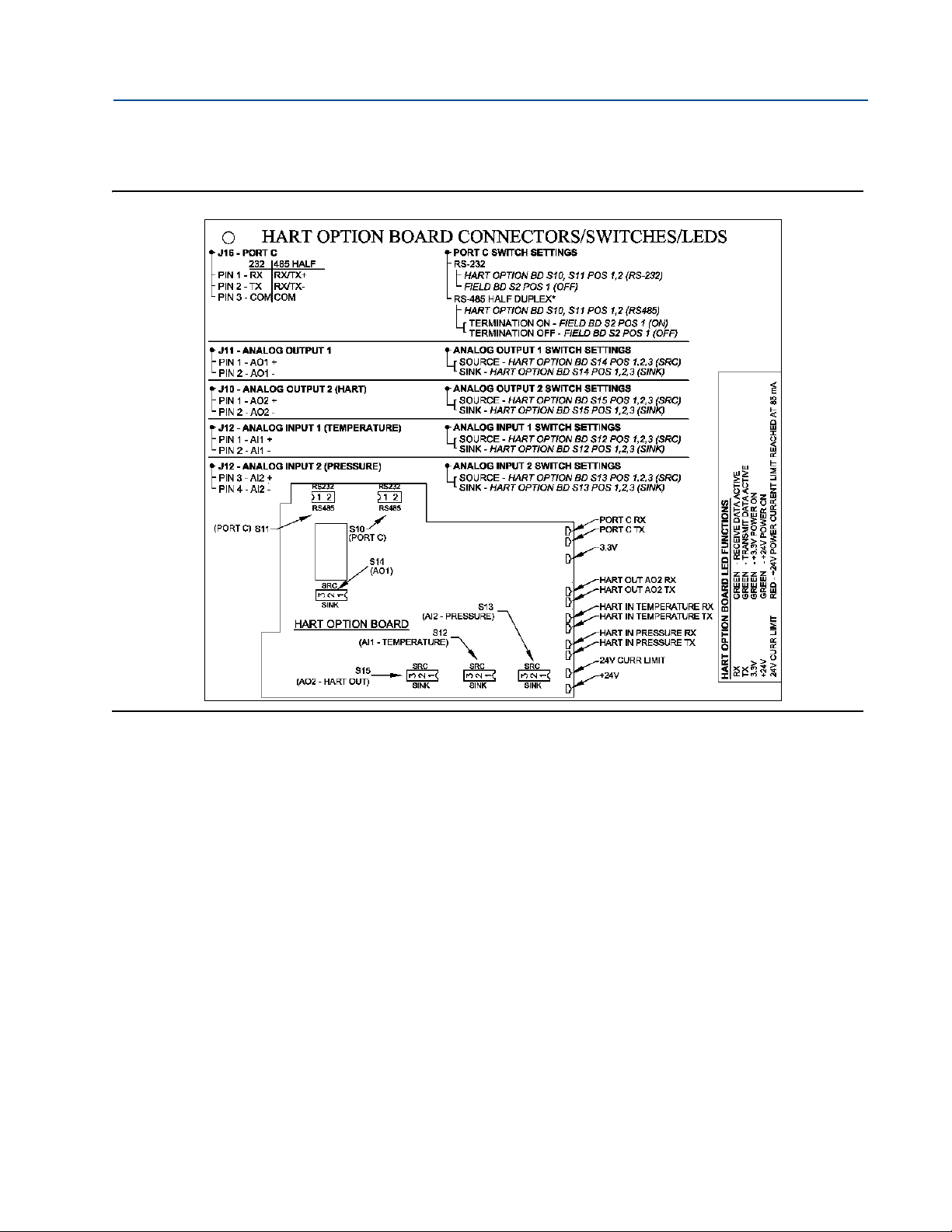
Reference, Installation, and Operations Manual Section 3: Installation
3-9000-743 Rev S June 2013
Figure 3-19 Series 100 Plus Option Board Wiring Connectors/Switches/LEDs
Hardware Switch Settings 69
Page 94

Section 3: Installation Reference, Installation, and Operations Manual
Port A Switches
S 3: 1-4, S 6: 1-2
S 2
Port B Switches
(RS-232/RS-485)
S 4: 1-4, S 5: 1,
S 7: 1-2and
and S 5: 1
(RS-232/RS-485)
S 4
S 3
S 6
S 7
S 5
S 2
June 2013 3-9000-743 Rev S
Figure 3-20 CPU Board Switches
70 Hardware Switch Settings
Page 95

Reference, Installation, and Operations Manual Section 3: Installation
Comm Port C Switches
RS-232 and RS-485
Analog In
(Temperature)
Switch
Analog In
(Pressure)
Switch
Analog Out
Switch
LED Communication
and Status Indicators
S14
S13
S10
S11
S12
3-9000-743 Rev S June 2013
Figure 3-21 Series 100 Option Board Switches
Hardware Switch Settings 71
Page 96

Section 3: Installation Reference, Installation, and Operations Manual
Analog In 1
(Temperature)
Analog In 2
(Pressure)
LED Communication
and Status Indicators
S10
S11
S12
S14
S13
S15
Analog Out 2
Analog Out 1
(HART capable)
Comm Port C Switches
RS-232 and RS-485
June 2013 3-9000-743 Rev S
Figure 3-22 Series 100 Plus Option Board Switches
72 Hardware Switch Settings
Page 97

Reference, Installation, and Operations Manual Section 3: Installation
Switch S2
Switch S1
S 3
S 4
S 7 S 5
S 6
Field Connection Board
CPU Board
1
S1: 1-4
S1: 5-8
Port A
Port B
1
1
2
3
4
5
6
7
8
3-9000-743 Rev S June 2013
Figure 3-23 Field Connection board switches
3.5.1 Communication settings
Communication Ports A and B are configured via switches on both the CPU and Field
Connection Boards (see Figure 3-24).
Figure 3-24 Field Connection and CPU Board communication configuration switch banks
Communication settings 73
Page 98

Section 3: Installation Reference, Installation, and Operations Manual
Serial ports (Port A and Port B) have isolated and floating grounds (50 VDC isolation). Their
grounds must be connected for reliable serial port operation. A shield may be connected
to ground at the remote end and can be used to provide ground for each por t. If both ports
are connected to the same remote location, the shield may be used to provide a common
ground back to the remote end.
June 2013 3-9000-743 Rev S
Serial Communication Port Drivers
For serial communication Ports A and B, the driver to be used is individually selectable between
RS-232, RS-485 Half Duplex, and RS485 Full Duplex.
Port A Driver Configuration
The serial communication Port A driver is configured via CPU Board switch banks S3, S5, and S6
and Field Connection Board switch bank S1.
To configure Port A for RS-232 operation, set the switches as indicated in the table below (see
Figure 3-24 for switch bank locations).
Table 3-25 Port A driver settings
Board Switch Position
CPU S3-1 RS232
S3-2 RS232
S3-3 RS232
S3-4 RS232
S5-1 FULL
S6-1 RS232
S6-2 RS232
Field Connection S1-1 TERM OFF
S1-2 TERM OFF
S1-3 FULL DUPLX
S1-4 FULL DUPLX
74 Communication settings
Page 99

Reference, Installation, and Operations Manual Section 3: Installation
Termination should only be enabled if the meter is the last drop in a multi-drop
configuration or the only meter in a single-drop configuration.
3-9000-743 Rev S June 2013
To configure Port A for RS-485 Full Duplex operation, set the switches as indicated in the table
below (see Figure 3-24 for switch bank locations):
Table 3-26 Port A RS-485 full duplex settings
Board Switch Position
CPU S3-1 RS485
S3-2 RS485
S3-3 RS485
S3-4 RS485
S5-1 FULL
S6-1 RS485
S6-2 RS485
Field Connection Termination ON Termination OFF
S1-1 TERM ON (RX) TERM OFF (RX)
S1-2 TERM ON (TX) TERM OFF (TX)
S1-3 FULL DUPLX
S1-4 FULL DUPLX
To configure Port A for RS-485 Half Duplex operation, set the switches as indicated in the table
below (see Figure 3-24 for switch bank locations):
Table 3-27 Port A RS-485 half duplex settings
Board Switch Position
CPU S3-1 RS485
S3-2 RS485
S3-3 RS485
S3-4 RS485
S5-1 HALF
S6-1 RS485
S6-2 RS485
Field Connection Termination ON Termination OFF
S1-1 TERM ON TERM OFF
S1-2 TERM OFF TERM OFF
S1-3 HALF DUPLX
S1-4 HALF DUPLX
Communication settings 75
Page 100

Section 3: Installation Reference, Installation, and Operations Manual
It is the action of changing S2-1 from the OPEN to CLOSED position (not being in the CLOSED
position) that causes the override mode to be entered.
June 2013 3-9000-743 Rev S
Port B Driver Configuration
The serial communication Port B driver is configured via CPU Board switch banks S4, S5, and S7
and Field Connection Board switch bank S1.
Port B supports a special override mode which forces the port to use known communication
values (19200 baud, address 32). (Note that the protocol is auto-detected.) This mode is
expected to be used during meter commissioning (to establish initial communication) and in
the event that the user cannot communicate with the meter (possibly due to an inadvertent
communication configuration change).
The Port B communication override mode is entered by switching CPU Board S2-1 (switch
bank 2, position 1) from the OPEN position to the CLOSED position. Port B remains in the
override mode until either (1) the port configuration is changed (via software), (2) two minutes
has elapsed (at which time the port reverts to its current configuration), or (3) the S2-1 switch is
changed back to the OPEN position.
To configure Port B for RS-232 operation, set the switches as indicated in the table below (see
Figure 3-24 for switch bank locations):
Table 3-28 Port B RS-232 driver settings
Board Switch Position
CPU S4-1 RS232
S4-2 RS232
S5-2 FULL
S7-1 RS232
S7-2 RS232
Field Connection S1-5 TERM OFF
S1-6 TERM 0FF
S1-7 FULL DUPLX
S1-8 FULL DUPLX
76 Communication settings
 Loading...