

Page 1
Reference Manual
b
00809-0100-4021, Rev DA
November 2004
Rosemount 3144P Temperature Transmitter
This product is a core
component of the PlantWe
digital plant architecture.
www.rosemount.com
Page 2

Page 3

Reference Manual
00809-0100-4021, Rev DA
November 2004
Rosemount 3144P
Rosemount 3144P Temperature
Transmitter
NOTICE
Read this manual before working with the product. For personal and system safety, and for
optimum product performance, make sure you thoroughly understand the contents before
installing, using, or maintaining this product.
Within the United States, Rosemount Inc. has two toll-free assistance numbers:
Customer Central
Technical support, quoting, and order-related questions.
1-800-999-9307 (7:00 am to 7:00 pm CST)
North American Response Center
Equipment service needs.
1-800-654-7768 (24 hours)
International
(952)-906-8888
The products described in this document are NOT designed for nuclear-qualified
applications. Using non-nuclear qualified products in applications that require
nuclear-qualified hardware or products may cause inaccurate readings.
For information on Rosemount nuclear-qualified products, contact your local Emerson
Process Management Sales Representative.
Rosemount 3144P Temperature Transmitter may be protected by one or more U.S. Patents
Pending. Other foreign patents pending.
www.rosemount.com
Page 4

Page 5

Reference Manual
00809-0100-4021, Rev DA
November 2004
Table of Contents
Rosemount 3144P
SECTION 1
Introduction
SECTION 2
Installation
Overview . . . . . . . . . . . . . . . . . . . . . . . . . . . . . . . . . . . . . . . . . . . . . . . 1-1
Manual . . . . . . . . . . . . . . . . . . . . . . . . . . . . . . . . . . . . . . . . . . . . . . 1-1
Transmitter . . . . . . . . . . . . . . . . . . . . . . . . . . . . . . . . . . . . . . . . . . . 1-2
Considerations. . . . . . . . . . . . . . . . . . . . . . . . . . . . . . . . . . . . . . . . . . . 1-2
General. . . . . . . . . . . . . . . . . . . . . . . . . . . . . . . . . . . . . . . . . . . . . . 1-2
Electrical . . . . . . . . . . . . . . . . . . . . . . . . . . . . . . . . . . . . . . . . . . . . . 1-2
Environmental. . . . . . . . . . . . . . . . . . . . . . . . . . . . . . . . . . . . . . . . . 1-3
Moist or Corrosive Environments . . . . . . . . . . . . . . . . . . . . . . . . . . 1-3
Mounting. . . . . . . . . . . . . . . . . . . . . . . . . . . . . . . . . . . . . . . . . . . . . 1-4
Software Compatibility . . . . . . . . . . . . . . . . . . . . . . . . . . . . . . . . . . 1-4
Return of Materials . . . . . . . . . . . . . . . . . . . . . . . . . . . . . . . . . . . . . . . 1-5
Rosemount 3144P and Rosemount 3144 / 3244MV Differences . . . . 1-6
Safety Messages . . . . . . . . . . . . . . . . . . . . . . . . . . . . . . . . . . . . . . . . . 2-1
Commissioning . . . . . . . . . . . . . . . . . . . . . . . . . . . . . . . . . . . . . . . . . . 2-2
Setting the Loop to Manual. . . . . . . . . . . . . . . . . . . . . . . . . . . . . . . 2-2
Set the Switches. . . . . . . . . . . . . . . . . . . . . . . . . . . . . . . . . . . . . . . 2-3
Mounting . . . . . . . . . . . . . . . . . . . . . . . . . . . . . . . . . . . . . . . . . . . . . . . 2-4
Installation . . . . . . . . . . . . . . . . . . . . . . . . . . . . . . . . . . . . . . . . . . . . . . 2-6
Typical North American Installation . . . . . . . . . . . . . . . . . . . . . . . . 2-6
Typical European Installation . . . . . . . . . . . . . . . . . . . . . . . . . . . . . 2-7
In Conjunction with a Rosemount 333 HART Tri-Loop
(HART / 4–20 mA only) . . . . . . . . . . . . . . . . . . . . . . . . . . . . . . . . . 2-8
LCD Display . . . . . . . . . . . . . . . . . . . . . . . . . . . . . . . . . . . . . . . . . . 2-9
Multichannel Installation (HART / 4–20 mA only) . . . . . . . . . . . . . 2-10
Wiring. . . . . . . . . . . . . . . . . . . . . . . . . . . . . . . . . . . . . . . . . . . . . . . . . 2-10
HART / 4–20 mA . . . . . . . . . . . . . . . . . . . . . . . . . . . . . . . . . . . . . 2-10
Foundation Fieldbus. . . . . . . . . . . . . . . . . . . . . . . . . . . . . . . . . . . 2-13
Sensor Connections . . . . . . . . . . . . . . . . . . . . . . . . . . . . . . . . . . . 2-14
Power Supply. . . . . . . . . . . . . . . . . . . . . . . . . . . . . . . . . . . . . . . . . . . 2-14
Surges/Transients . . . . . . . . . . . . . . . . . . . . . . . . . . . . . . . . . . . . 2-15
Grounding. . . . . . . . . . . . . . . . . . . . . . . . . . . . . . . . . . . . . . . . . . . 2-15
www.rosemount.com
Page 6

Rosemount 3144P
Reference Manual
00809-0100-4021, Rev DA
November 2004
SECTION 3
HART Commissioning
Overview . . . . . . . . . . . . . . . . . . . . . . . . . . . . . . . . . . . . . . . . . . . . . . . 3-1
Safety Messages . . . . . . . . . . . . . . . . . . . . . . . . . . . . . . . . . . . . . . . . . 3-1
375 Field Communicator . . . . . . . . . . . . . . . . . . . . . . . . . . . . . . . . . . . 3-2
Updating the HART Communication Software . . . . . . . . . . . . . . . . 3-2
Menu Tree . . . . . . . . . . . . . . . . . . . . . . . . . . . . . . . . . . . . . . . . . . . 3-3
Fast Key Sequences . . . . . . . . . . . . . . . . . . . . . . . . . . . . . . . . . . . 3-4
AMS. . . . . . . . . . . . . . . . . . . . . . . . . . . . . . . . . . . . . . . . . . . . . . . . . . . 3-5
Apply AMS Changes . . . . . . . . . . . . . . . . . . . . . . . . . . . . . . . . . . . 3-5
Review Configuration Data . . . . . . . . . . . . . . . . . . . . . . . . . . . . . . . . . 3-5
Check Output. . . . . . . . . . . . . . . . . . . . . . . . . . . . . . . . . . . . . . . . . . . . 3-6
Configuration . . . . . . . . . . . . . . . . . . . . . . . . . . . . . . . . . . . . . . . . . . . . 3-6
Device Output Configuration . . . . . . . . . . . . . . . . . . . . . . . . . . . . . . . 3-14
Device Information. . . . . . . . . . . . . . . . . . . . . . . . . . . . . . . . . . . . . . . 3-18
Measurement Filtering. . . . . . . . . . . . . . . . . . . . . . . . . . . . . . . . . . . . 3-19
Diagnostics and Service . . . . . . . . . . . . . . . . . . . . . . . . . . . . . . . . . . 3-21
Multidrop Communication . . . . . . . . . . . . . . . . . . . . . . . . . . . . . . . . . 3-24
Use with the HART Tri-Loop . . . . . . . . . . . . . . . . . . . . . . . . . . . . . . . 3-25
Calibration . . . . . . . . . . . . . . . . . . . . . . . . . . . . . . . . . . . . . . . . . . . . . 3-28
Trim the Transmitter . . . . . . . . . . . . . . . . . . . . . . . . . . . . . . . . . . . . . 3-28
Sensor Input Trim . . . . . . . . . . . . . . . . . . . . . . . . . . . . . . . . . . . . . 3-29
Transmitter-Sensor Matching . . . . . . . . . . . . . . . . . . . . . . . . . . . . 3-32
D/A Output Trim or Scaled Output Trim . . . . . . . . . . . . . . . . . . . . 3-33
Output Trim. . . . . . . . . . . . . . . . . . . . . . . . . . . . . . . . . . . . . . . . . . 3-33
Scaled Output Trim. . . . . . . . . . . . . . . . . . . . . . . . . . . . . . . . . . . . 3-34
Troubleshooting. . . . . . . . . . . . . . . . . . . . . . . . . . . . . . . . . . . . . . . . . 3-35
HART / 4–20 mA . . . . . . . . . . . . . . . . . . . . . . . . . . . . . . . . . . . . . 3-35
LCD Display . . . . . . . . . . . . . . . . . . . . . . . . . . . . . . . . . . . . . . . . . 3-38
AMS Software (HART / 4-20 mA only) . . . . . . . . . . . . . . . . . . . . . 3-39
AMS Screens . . . . . . . . . . . . . . . . . . . . . . . . . . . . . . . . . . . . . . . . 3-41
SECTION 4
Foundation Fieldbus
Configuration
Overview . . . . . . . . . . . . . . . . . . . . . . . . . . . . . . . . . . . . . . . . . . . . . . . 4-1
Safety Messages . . . . . . . . . . . . . . . . . . . . . . . . . . . . . . . . . . . . . . . . . 4-1
General Block Information . . . . . . . . . . . . . . . . . . . . . . . . . . . . . . . . . . 4-2
Device Description . . . . . . . . . . . . . . . . . . . . . . . . . . . . . . . . . . . . . 4-2
Node Address. . . . . . . . . . . . . . . . . . . . . . . . . . . . . . . . . . . . . . . . . 4-2
Modes. . . . . . . . . . . . . . . . . . . . . . . . . . . . . . . . . . . . . . . . . . . . . . . 4-2
Link Active Scheduler . . . . . . . . . . . . . . . . . . . . . . . . . . . . . . . . . . . 4-3
Block Instantiation . . . . . . . . . . . . . . . . . . . . . . . . . . . . . . . . . . . . . 4-3
Capabilities . . . . . . . . . . . . . . . . . . . . . . . . . . . . . . . . . . . . . . . . . . . 4-4
Foundation fieldbus function blocks. . . . . . . . . . . . . . . . . . . . . . . . . . . 4-4
Resource Block . . . . . . . . . . . . . . . . . . . . . . . . . . . . . . . . . . . . . . . . . . 4-5
FEATURES and FEATURES_SEL . . . . . . . . . . . . . . . . . . . . . . . . 4-5
PlantWeb
Recommended Actions for PlantWeb Alerts . . . . . . . . . . . . . . . . . 4-9
Resource Block Diagnostics. . . . . . . . . . . . . . . . . . . . . . . . . . . . . . 4-9
Sensor Transducer Block . . . . . . . . . . . . . . . . . . . . . . . . . . . . . . . . . 4-10
Damping . . . . . . . . . . . . . . . . . . . . . . . . . . . . . . . . . . . . . . . . . . . . 4-10
Sensor Transducer Block Diagnostics . . . . . . . . . . . . . . . . . . . . . 4-10
LCD Transducer Block. . . . . . . . . . . . . . . . . . . . . . . . . . . . . . . . . . . . 4-11
Custom Meter Configuration. . . . . . . . . . . . . . . . . . . . . . . . . . . . . 4-12
Self Test Procedure for the LCD . . . . . . . . . . . . . . . . . . . . . . . . . 4-13
LCD Transducer Block Diagnostics . . . . . . . . . . . . . . . . . . . . . . . 4-13
™
Alerts. . . . . . . . . . . . . . . . . . . . . . . . . . . . . . . . . . . . . . 4-7
TOC-2
Page 7

Reference Manual
00809-0100-4021, Rev DA
November 2004
Rosemount 3144P
Analog Input (AI) . . . . . . . . . . . . . . . . . . . . . . . . . . . . . . . . . . . . . . . . 4-14
Simulation. . . . . . . . . . . . . . . . . . . . . . . . . . . . . . . . . . . . . . . . . . . 4-14
Configure the AI block . . . . . . . . . . . . . . . . . . . . . . . . . . . . . . . . . 4-14
Filtering. . . . . . . . . . . . . . . . . . . . . . . . . . . . . . . . . . . . . . . . . . . . . 4-17
Process Alarms . . . . . . . . . . . . . . . . . . . . . . . . . . . . . . . . . . . . . . 4-17
Status . . . . . . . . . . . . . . . . . . . . . . . . . . . . . . . . . . . . . . . . . . . . . . 4-18
Advanced Features . . . . . . . . . . . . . . . . . . . . . . . . . . . . . . . . . . . 4-18
Analog Input Diagnostics . . . . . . . . . . . . . . . . . . . . . . . . . . . . . . . 4-19
Operation. . . . . . . . . . . . . . . . . . . . . . . . . . . . . . . . . . . . . . . . . . . . . . 4-20
Overview. . . . . . . . . . . . . . . . . . . . . . . . . . . . . . . . . . . . . . . . . . . . 4-20
Trim the Transmitter . . . . . . . . . . . . . . . . . . . . . . . . . . . . . . . . . . . 4-20
Statistical Process Monitoring (SPM) . . . . . . . . . . . . . . . . . . . . . . 4-22
SPM Configuration . . . . . . . . . . . . . . . . . . . . . . . . . . . . . . . . . . 4-23
Troubleshooting Guides. . . . . . . . . . . . . . . . . . . . . . . . . . . . . . . . . . . 4-25
Foundation Fieldbus. . . . . . . . . . . . . . . . . . . . . . . . . . . . . . . . . . . 4-28
LCD Display . . . . . . . . . . . . . . . . . . . . . . . . . . . . . . . . . . . . . . . . . 4-29
SECTION 5
Maintenance
SECTION 6
Certified Safety
Instrumented System
(SIS)
Safety Messages . . . . . . . . . . . . . . . . . . . . . . . . . . . . . . . . . . . . . . . . . 5-1
Maintenance . . . . . . . . . . . . . . . . . . . . . . . . . . . . . . . . . . . . . . . . . . . . 5-2
Test Terminal (HART / 4–20 mA only) . . . . . . . . . . . . . . . . . . . . . . 5-2
Sensor Checkout . . . . . . . . . . . . . . . . . . . . . . . . . . . . . . . . . . . . . . 5-2
Electronics Housing . . . . . . . . . . . . . . . . . . . . . . . . . . . . . . . . . . . . 5-2
Safety Messages . . . . . . . . . . . . . . . . . . . . . . . . . . . . . . . . . . . . . . . . . 6-1
Certification . . . . . . . . . . . . . . . . . . . . . . . . . . . . . . . . . . . . . . . . . . . . . 6-1
3144P SIS Identification . . . . . . . . . . . . . . . . . . . . . . . . . . . . . . . . . . . 6-1
Installation . . . . . . . . . . . . . . . . . . . . . . . . . . . . . . . . . . . . . . . . . . . . . . 6-2
Commissioning . . . . . . . . . . . . . . . . . . . . . . . . . . . . . . . . . . . . . . . . . . 6-2
Configuration . . . . . . . . . . . . . . . . . . . . . . . . . . . . . . . . . . . . . . . . . . . . 6-2
SIS Additions . . . . . . . . . . . . . . . . . . . . . . . . . . . . . . . . . . . . . . . . . 6-3
Transmitter Diagnostics Logging . . . . . . . . . . . . . . . . . . . . . . . . . . . . . 6-3
375 Field communicator . . . . . . . . . . . . . . . . . . . . . . . . . . . . . . . . . 6-4
3144P SIS Menu Tree . . . . . . . . . . . . . . . . . . . . . . . . . . . . . . . . . . 6-4
3144P SIS Fast Key Sequences . . . . . . . . . . . . . . . . . . . . . . . . . . 6-5
Operation and Maintenance . . . . . . . . . . . . . . . . . . . . . . . . . . . . . . . . 6-6
Proof Test . . . . . . . . . . . . . . . . . . . . . . . . . . . . . . . . . . . . . . . . . . . . 6-6
Inspection . . . . . . . . . . . . . . . . . . . . . . . . . . . . . . . . . . . . . . . . . . . . 6-7
Specifications. . . . . . . . . . . . . . . . . . . . . . . . . . . . . . . . . . . . . . . . . . . . 6-7
Failure Rate Data . . . . . . . . . . . . . . . . . . . . . . . . . . . . . . . . . . . . . . 6-7
Product Life . . . . . . . . . . . . . . . . . . . . . . . . . . . . . . . . . . . . . . . . . . 6-7
Spare Parts . . . . . . . . . . . . . . . . . . . . . . . . . . . . . . . . . . . . . . . . . . . . . 6-7
SECTION 7
Prior Use (PU) Safety
Instrumented System
Overview . . . . . . . . . . . . . . . . . . . . . . . . . . . . . . . . . . . . . . . . . . . . . . . 7-1
Safe Failure Fraction . . . . . . . . . . . . . . . . . . . . . . . . . . . . . . . . . . . . . . 7-2
Installation . . . . . . . . . . . . . . . . . . . . . . . . . . . . . . . . . . . . . . . . . . . . . . 7-2
Switches . . . . . . . . . . . . . . . . . . . . . . . . . . . . . . . . . . . . . . . . . . . . . 7-2
Changing Switch Position. . . . . . . . . . . . . . . . . . . . . . . . . . . . . . . . 7-3
TOC-3
Page 8

Rosemount 3144P
Reference Manual
00809-0100-4021, Rev DA
November 2004
APPENDIX A
Reference Data
APPENDIX B
Product Certifications
HART and Foundation Fieldbus Specifications . . . . . . . . . . . . . . . . . .A-1
Functional Specifications . . . . . . . . . . . . . . . . . . . . . . . . . . . . . . . . A-1
Physical Specifications . . . . . . . . . . . . . . . . . . . . . . . . . . . . . . . . . .A-1
Performance Specifications . . . . . . . . . . . . . . . . . . . . . . . . . . . . . . A-2
HART / 4–20 mA Specifications . . . . . . . . . . . . . . . . . . . . . . . . . . . . .A-6
Foundation Fieldbus Specifications. . . . . . . . . . . . . . . . . . . . . . . . . . . A-8
Dimensional Drawings. . . . . . . . . . . . . . . . . . . . . . . . . . . . . . . . . . . .A-10
Ordering Information . . . . . . . . . . . . . . . . . . . . . . . . . . . . . . . . . . . . . A-14
Rosemount 3144P With HART / 4–20 mA. . . . . . . . . . . . . . . . . . . . . . B-1
Approved Manufacturing Locations . . . . . . . . . . . . . . . . . . . . . . . . B-1
European Union Directive Information . . . . . . . . . . . . . . . . . . . . . . B-1
Hazardous Locations Installations . . . . . . . . . . . . . . . . . . . . . . . . . B-1
Rosemount 3144P With Foundation fieldbus . . . . . . . . . . . . . . . . . . .B-6
Approved Manufacturing Locations . . . . . . . . . . . . . . . . . . . . . . . . B-6
European Union Directive Information . . . . . . . . . . . . . . . . . . . . . . B-6
Hazardous Locations Installations . . . . . . . . . . . . . . . . . . . . . . . . . B-6
Installation Drawings . . . . . . . . . . . . . . . . . . . . . . . . . . . . . . . . . . . . . . B-9
TOC-4
Page 9

Reference Manual
00809-0100-4021, Rev DA
November 2004
Rosemount 3144P
Section 1 Introduction
Overview . . . . . . . . . . . . . . . . . . . . . . . . . . . . . . . . . . . . . . . page 1-1
Considerations . . . . . . . . . . . . . . . . . . . . . . . . . . . . . . . . . . page 1-2
Return of Materials . . . . . . . . . . . . . . . . . . . . . . . . . . . . . . . page 1-5
Rosemount 3144P and Rosemount 3144 / 3244MV Differences page 1-6
OVERVIEW
Manual This manual is designed to assist in the installation, operation, and
maintenance of the Rosemount 3144P.
Section 1: Introduction
• Transmitter and Manual Overview
• Considerations
• Return of Material
Section 2: Installation
• Mounting
• Installation
• Wiring
• Power Supply
Section 3: HART Configuration
• 375 Field Communicator
• Configuration
• Multidrop Communication
• Calibration
• Trim the transmitter
Section 4: F
• Calibration
• Hardware Maintenance
• Diagnostic Messaging
• Trim the Transmitter
Section 5: Operation and Maintenance
• Maintenance
• Troubleshooting
OUNDATION Fieldbus Configuration
www.rosemount.com
Page 10

Rosemount 3144P
Appendix A: Specifications and Reference Data
• Specifications
• Dimensional drawings
• Ordering Information
Appendix B: Approvals
• Product Certifications
• Installation Drawings
Safety Instrumented System (SIS) – HART only
• Information regarding Safety Certified transmitters
Transmitter Features of the Rosemount 3144P include:
• Accepts inputs from a wide variety of sensors
• Configuration using HART protocol or F
• Electronics that are completely encapsulated in epoxy and enclosed in
a metal housing, making the transmitter extremely durable and
ensuring long-term reliability
• A compact size and two housing options allowing mounting flexibility for
the control room or the field
• Special dual-sensor features include Hot Backup
first good, differential and average temperature measurements, and
four simultaneous measurement variable outputs in addition to the
analog output signal
Reference Manual
00809-0100-4021, Rev DA
November 2004
OUNDATION fieldbus
®
, sensor drift alarm,
Refer to the following literature for a full range of compatible connection
heads, sensors, and thermowells provided by Emerson Process
Management.
• Temperature Sensors and Assemblies Product Data Sheet, Volume 1
(document number 00813-0100-2654)
• Temperature Sensors and Assemblies Product Data Sheet, Metric
(document number 00813-0200-2654)
CONSIDERATIONS
General Electrical temperature sensors, such as resistance temperature detectors
(RTDs) and thermocouples (T/Cs), produce low-level signals proportional to
temperature. The 3144P transmitter converts low-level signals to HART or
F
OUNDATION fieldbus signals. This signal is then transmitted to the control
room via two power/signal wires.
Electrical Proper electrical installation is essential to prevent errors due to sensor lead
resistance and electrical noise. The current loop must have between 250 and
1100 ohms resistance for HART communications. Refer to Figure 2-10 on
page 2-11 for sensor and current loop connections. F
devices must have proper termination and power conditioning for reliable
operation. Shield cables must be used for F
may only be grounded in one place.
OUNDATION fieldbus and the shield
OUNDATION fieldbus
1-2
Page 11
Reference Manual
00809-0100-4021, Rev DA
November 2004
Environmental Temperature Effects
The transmitter will operate within specifications for ambient temperatures
between –40 and 185 °F (–40 and 85 °C). Heat from the process is
transferred from the thermowell to the transmitter housing. If the expected
process temperature is near or beyond specification limits, consider the use of
additional thermowell lagging, an extension nipple, or a remote mounting
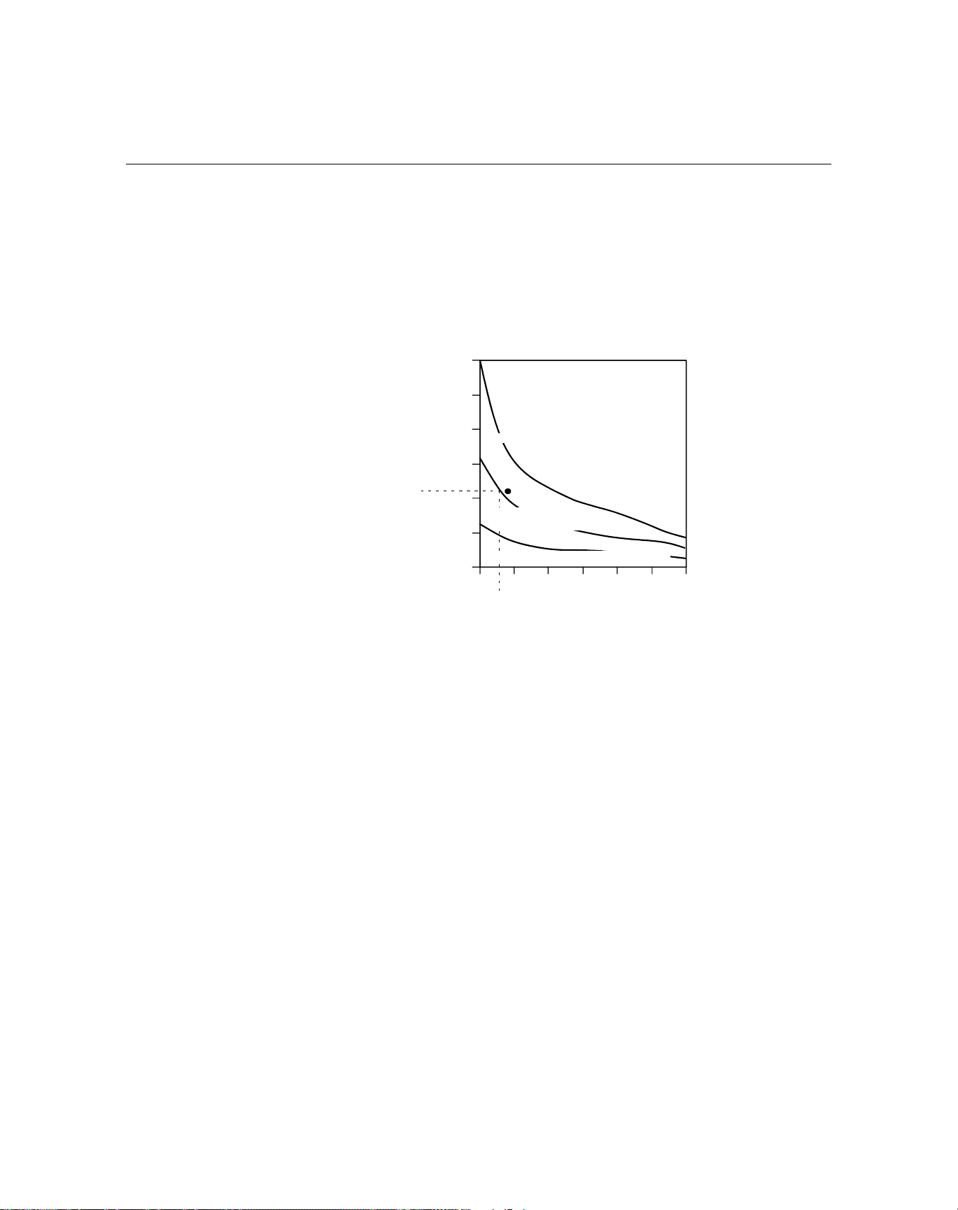
configuration to isolate the transmitter from the process. Figure 1-1 describes
the relationship between housing temperature rise and extension length.
Rosemount 3144P
Figure 1-1. 3144P Transmitter
Housing Temperature Rise
versus Extension Length for a
Test Installation.
60 (108)
50 (90)
40 (72)
30 (54)
22
Ambient °C (°F)
Housing Temperature Rise, Above
20 (36)
10 (18)
815 °C (1500 °F) Oven Temperature
540 °C (1000 °F)
Oven Temperature
250 °C (482 °F) Oven Temperature
0
3 4 5 6 7 8 9
3.6
Extension Length (in.)
Example:
The maximum permissible housing temperature rise (T) can be calculated
by subtracting the maximum ambient temperature (A) from the
transmitter’s ambient temperature specification limit (S). For instance,
suppose A = 40 °C.
T = S - A
T = 85 °C – 40 °C
T = 45 °C
3044-0123A
Moist or Corrosive
Environments
For a process temperature of 540 °C (1004 °F), an extension length of 3.6
inches (91.4 mm) yields a housing temperature rise (R) of 22 °C (72 °F),
which provides a safety margin of 23 °C (73 °F). A six-inch extension
length (R = 10 °C (50 °F)) would offer a higher safety margin (35 °C (95
°F)) and would reduce temperature-effect errors but would probably
require extra transmitter support. Gauge the requirements for individual
applications along this scale. If a thermowell with lagging is used, the
extension length may be reduced by the length of the lagging.
The 3144P temperature transmitter has a highly reliable dual compartment
housing designed to resist moisture and corrosion. The sealed electronics
module is mounted in a compartment that is isolated from the terminal side
conduit entries. O-ring seals protect the interior when the covers are properly
installed. In humid environments, however, it is possible for moisture to
accumulate in conduit lines and drain into the housing.
1-3
Page 12

Reference Manual
00809-0100-4021, Rev DA
Rosemount 3144P
NOTE
Each transmitter is marked with a tag indicating the approvals. Install the
transmitter in accordance with all applicable installation codes and approval
and installation drawings (see Appendix B: Product Certifications). Verify that
the operating atmosphere of the transmitter is consistent with the hazardous
locations certifications. Once a device labeled with multiple approval types is
installed, it should not be reinstalled using any of the other labeled approval
types. To ensure this, the approval label should be permanently marked to
distinguish the used from the unused approval type(s).
November 2004
Mounting Take into account the need for access to the transmitter when choosing an
installation location and position.
Terminal Side of Electronics Housing
Mount the transmitter so the terminal side is accessible. Allow adequate
clearance for cover removal. Make wiring connections through the conduit
openings on the bottom of the housing.
Circuit Side of Electronics Housing
Mount the transmitter so the circuit side is accessible. Provide adequate
clearance for cover removal. Additional room is required for LCD installation.
The transmitter may be mounted directly to or remotely from the sensor.
Using optional mounting brackets, the transmitter may be mounted to a flat
surface or to a two-inch diameter pipe (see “Optional Transmitter Mounting
Brackets” on page A-8).
Software Compatibility Replacement transmitters may contain revised software that is not fully
compatible with the existing software. The 375 Field Communicator and AMS
software containing device descriptors for the 3144 and 3244MV before
December 2001 do not fully support the new features of the 3144P. The
Device Descriptors (DD) are available with new communicators or can be
loaded into existing communicators at any Emerson Process Management
Service Center.
1-4
Page 13

Reference Manual
00809-0100-4021, Rev DA
November 2004
Rosemount 3144P
RETURN OF MATERIALS To expedite the return process in North America, call the Emerson Process
Management National Response Center (800-654-7768). This center, will
assist you with any needed information or materials.
The center will ask for the following information:
• Product model
• Serial numbers
• The last process material to which the product was exposed
The center will provide
• A Return Material Authorization (RMA) number
• Instructions and procedures that are necessary to return goods that
were exposed to hazardous substances
For other locations, contact a Emerson Process Management representative.
NOTE
If a hazardous substance is identified, a Material Safety Data Sheet (MSDS),
required by law to be available to people exposed to specific hazardous
substances, must be included with the returned materials.
1-5
Page 14

Rosemount 3144P
Reference Manual
00809-0100-4021, Rev DA
November 2004
ROSEMOUNT 3144P
AND ROSEMOUNT 3144 /
3244MV DIFFERENCES
The following table identifies the differences between the Rosemount 3144P
and Rosemount 3144 and 3244MV Temperature Transmitters.
Improved Rosemount 3144P Previous Rosemount 3144 and 3244MV
Field Device Revision number 3 Standard 3144P: Dev v3, DD v2
Software Revision number 3 Software Revision number 1
Added sensor input types: DIN Type L, DIN
Type U, and extended temperature range of
Type N
Uses custom-configurable alarm limits Analog output and alarm levels can be ordered
Improved 2- and 3-wire EMF compensation NA
First Good Temperature is available as a
device variable
2-wire fixed lead correction is available NA
Enhanced EMI rejection and filtering resulting
in unmatched stability in process measurement
Dual-sensor configuration is field selectable Rosemount 3144 – single sensor
3144P SIS: Dev v1, DD v1 (for SIS)
NA
to be NAMUR-compliant with option codes A1
and CN
NA
NA
Rosemount 3244MV – dual-sensor configuration
1-6
Page 15

Reference Manual
00809-0100-4021, Rev DA
November 2004
Rosemount 3144P
Section 2 Installation
Safety Messages . . . . . . . . . . . . . . . . . . . . . . . . . . . . . . . . . page 2-1
Commissioning . . . . . . . . . . . . . . . . . . . . . . . . . . . . . . . . . . page 2-2
Mounting . . . . . . . . . . . . . . . . . . . . . . . . . . . . . . . . . . . . . . . page 2-4
Installation . . . . . . . . . . . . . . . . . . . . . . . . . . . . . . . . . . . . . . page 2-6
Wiring . . . . . . . . . . . . . . . . . . . . . . . . . . . . . . . . . . . . . . . . . . page 2-10
Power Supply . . . . . . . . . . . . . . . . . . . . . . . . . . . . . . . . . . . page 2-14
SAFETY MESSAGES Instructions and procedures in this section may require special precautions to
ensure the safety of the personnel performing the operations. Information that
potentially raises safety issues is indicated by a warning symbol ( ). Please
refer to the following safety messages before performing an operation
preceded by this symbol.
Explosions could result in death or serious injury:
• Do not remove the transmitter cover in explosive atmospheres when the circuit
is live.
• Before connecting a 375 Field Communicator in an explosive atmosphere, make
sure the instruments in the loop are installed in accordance with intrinsically safe
or non-incendive field wiring practices.
• Verify that the operating atmosphere of the transmitter is consistent with the
appropriate hazardous locations certifications.
• Both transmitter covers must be fully engaged to meet explosion-proof
requirements.
Failure to follow these installation guidelines could result in death or serious injury:
• Make sure only qualified personnel perform the installation.
Process leaks could result in death or serious injury:
• Install and tighten thermowells or sensors before applying pressure, or process
leakage may result.
• Do not remove the thermowell while in operation. Removing while in operation
may cause process fluid leaks.
Electrical shock could cause death or serious injury. If the sensor is installed in a
high-voltage environment and a fault or installation error occurs, high voltage may be
present on the transmitter leads and terminals:
• Use extreme caution when making contact with the leads and terminals.
www.rosemount.com
Page 16
Reference Manual
00809-0100-4021, Rev DA
Rosemount 3144P
November 2004
COMMISSIONING The 3144P must be configured for certain basic variables to operate. In many
cases, all of these variables are pre-configured at the factory. Configuration
may be required if the configuration variables need to be changed.
Commissioning consists of testing the transmitter and verifying transmitter
configuration data. Rosemount 3144P transmitters can be commissioned
either before or after installation. Commissioning the transmitter on the bench
before installation using a 375 Field Communicator or AMS ensures that all
transmitter components are in working order.
For more information on using the Field Communicator with the 3144P
transmitter, see “HART Commissioning” on page 3-1. For more information on
using the 3144 with Foundation fieldbus, see “Foundation Fieldbus
Configuration” on page 4-1.
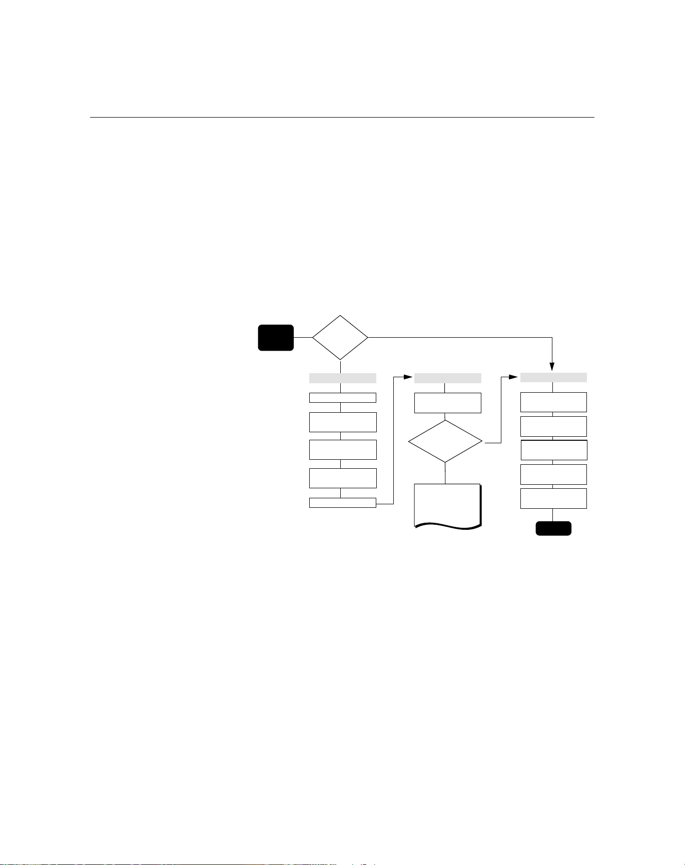
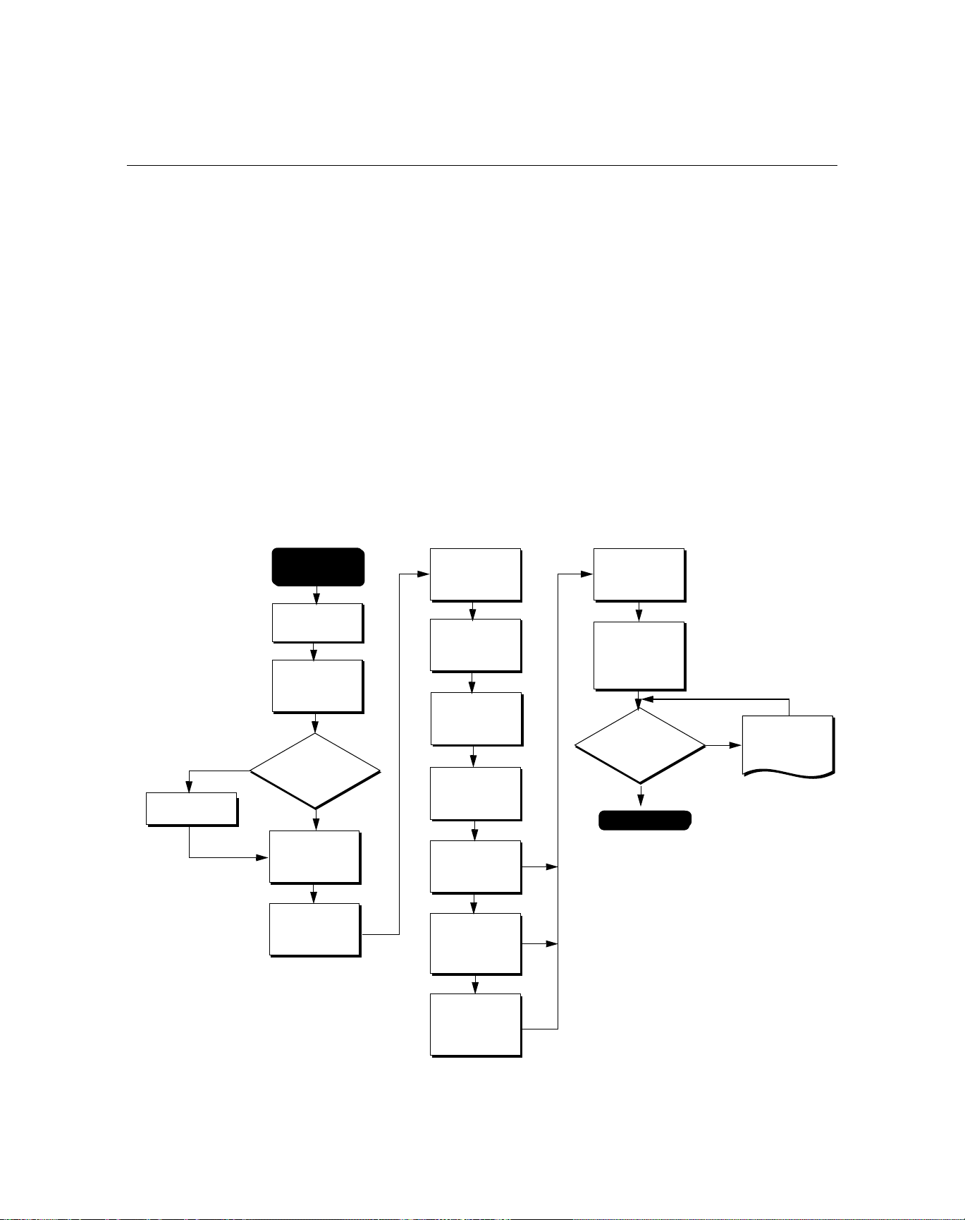
Figure 2-1. Installation
Flowchart.
START
HERE
Bench
Calibration?
Yes
BASIC SETUP
No
VERIFY
FIELD INSTALL
Setting the Loop to
Manual
Set Units
Set Range
Values - HART
Set Sensor
Typ es
Set Number
of Wires
Set Damping
Simulate
Sensor Input
Within
Specifications?
No
Refer to
Section 1:
Maintenance
Yes
Set Jumpers or
Switches
Mount the
Transmitter
Wire the
Transmitter
Power the
Transmitter
Check for
Process Leaks
Done
When sending or requesting data that would disrupt the loop or change the
output of the transmitter, set the process application loop to manual. The 375
Field Communicator or AMS will prompt you to set the loop to manual when
necessary. Acknowledging this prompt does not set the loop to manual. The
prompt is only a reminder; set the loop to manual as a separate operation.
2-2
Page 17

Reference Manual
00809-0100-4021, Rev DA
November 2004
Set the Switches HART
Without a LCD display
1. If the transmitter is installed in a loop, set the loop to manual mode and
2. Remove the housing cover on the electronics side of the transmitter.
3. Set the switches to the desired position (see Figure 2-1).
4. Replace the transmitter cover. Both transmitter covers must be fully
5. Apply power and set the loop to automatic mode.
With a LCD display
1. If the transmitter is installed in a loop, set the loop to manual mode and
2. Remove the housing cover on the electronics side of the transmitter.
3. Remove the housing cover, unscrew the LCD display screws and
4. Set the switches to the desired position (see Figure 2-1).
5. Gently slide the LCD display back into place, taking extra precautions
6. Secure the LCD display by replacing the LCD display screws.
7. Replace the transmitter cover. Both transmitter covers must be fully
8. Apply power and set the loop to automatic mode.
Rosemount 3144P
disconnect power.
Do not remove the transmitter cover in explosive atmospheres when
the circuit is live.
engaged to meet explosion-proof requirements.
disconnect power.
Do not remove the transmitter cover in explosive atmospheres when
the circuit is live.
gently slide the meter straight off.
of the 10 pin connection.
engaged to meet explosion-proof requirements.
Foundation Fieldbus
Without a LCD Display
1. If the transmitter is installed in a loop, set the loop to Out-of-Service
(OOS) mode (if applicable) and disconnect the power.
2. Remove the electronics housing cover.
3. Set the switches to the desired position. Reattach housing cover.
4. Apply power and set the loop to In-Service mode.
With a LCD Display
1. If the transmitter is installed in a loop, set the loop to Out-of-Service
(OOS) (if applicable) and disconnect the power.
2. Remove the electronics housing cover.
3. Unscrew the LCD display screws and pull the meter straight off.
4. Set the switches to the desired position.
5. Reattach the LCD display and electronics housing cover (consider LCD
display orientation).
6. Apply power and set the loop to In-Service mode.
2-3
Page 18

Rosemount 3144P
Table 2-1. Transmitter Switch
Locations.
Reference Manual
00809-0100-4021, Rev DA
November 2004
Switch Location
Switches
Write Protect Switch (HART and F
(1)
4.4 in. (112 mm)
(1) Alarm and Write Protect (HART),
Simulate and Write Protect (F
OUNDATION Fieldbus)
OUNDATION Fieldbus)
4.4 in. (112 mm)
LCD
Connector
The transmitter is equipped with a write-protect switch that can be positioned
to prevent the accidental or deliberate change of configuration data.
Alarm Switch (HART)
The transmitter monitors itself during normal operation with an automatic
diagnostic routine. If the diagnostic routine detects a sensor failure or a failure
in the transmitter electronics, the transmitter goes into alarm (high or low,
depending on the position of the failure mode switch).
The analog alarm and saturation values that the transmitter uses depend on
whether it is configured to standard or NAMUR-compliant operation. These
values are also custom-configurable in both the factory and the field using the
HART Communications. The limits are
•21.0 ≤ I ≤ 23 for high alarm
• 3.5 ≤ I ≤ 3.75 for low alarm
Table 2-2. Values for standard
and NAMUR operation
Standard Operation (factory default) NAMUR-Compliant Operation
Fail High 21.75 mA ≤ I ≤ 23.0 mA Fail High 21 mA ≤ I ≤ 23.0 mA
High Saturation I ≥ 20.5 mA High Saturation I ≥ 20.5 mA
Low Saturation I ≤ 3.90 mA Low Saturation I ≤ 3.8 mA
Fail Low I ≤ 3.75 mA Fail Low I ≤ 3.6 mA
Simulate Switch (F
OUNDATION Fieldbus)
Simulate switch is used to replaces the channel value coming from the
Sensor Transducer Block. For testing purposes, it manually simulates the
output of the Analog Input Block to a desired value.
MOUNTING If possible, mount the transmitter at a high point in the conduit run so moisture
from the conduits will not drain into the housing. The terminal compartment
could fill with water If the transmitter is mounted at a low point in the conduit
run. In some instances, the installation of a poured conduit seal, such as the
one pictured in Figure 2-3, is advisable. Remove the terminal compartment
cover periodically and inspect the transmitter for moisture and corrosion.
2-4
Page 19
Reference Manual
00809-0100-4021, Rev DA
November 2004
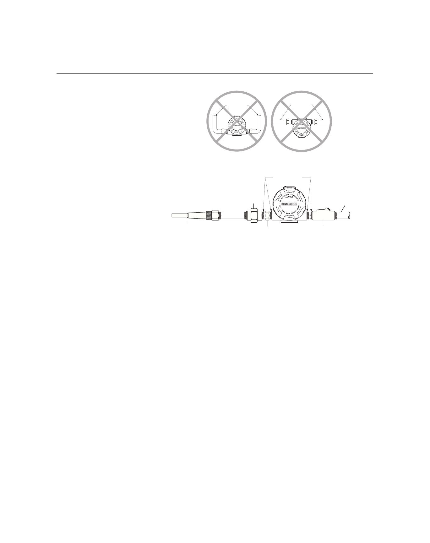
Figure 2-2. Incorrect Conduit
Installation
Conduit
Lines
Rosemount 3144P
Conduit
Lines
3144-0429A, 0429B
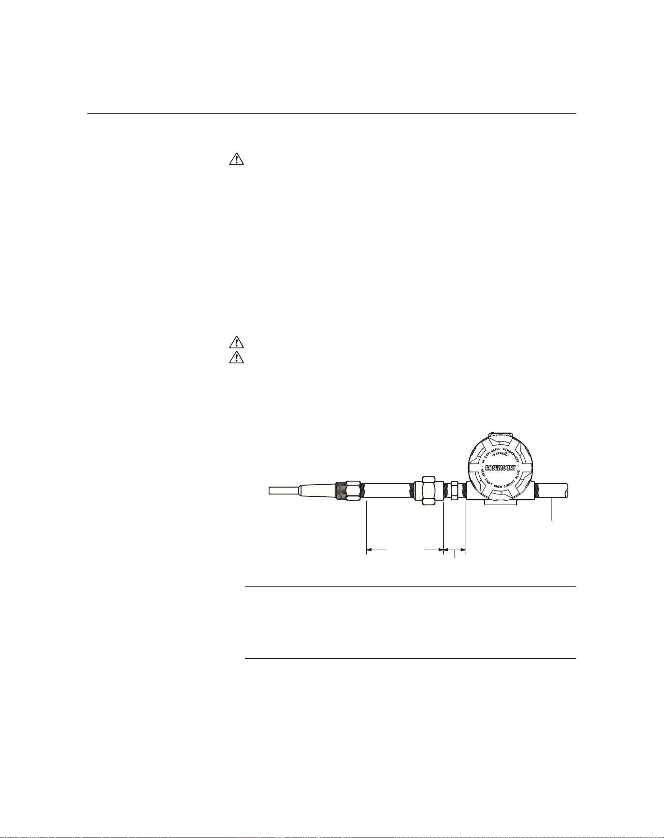
Figure 2-3. Recommended
Mounting with Drain Seal
Sealing
Compound
Union Coupling with Extension
Thermowell
Sensor Hex
Poured Conduit Seal (Where Required)
Conduit for
Field Wiring
If mounting the transmitter directly to the sensor assembly, use the process
shown in Figure 2-4. If mounting the transmitter apart from the sensor
assembly, use conduit between the sensor and transmitter. The transmitter
1
accepts male conduit fittings with
1
(PG 11), or JIS G
/2 threads (M20 × 1.5 (CM 20), PG 13.5 (PG 11), or JIS G1/2
/2–14 NPT, M20 × 1.5 (CM 20), PG 13.5
threads are provided by an adapter). Make sure only qualified personnel
perform the installation.
The transmitter may require supplementary support under high-vibration
conditions, particularly if used with extensive thermowell lagging or long
extension fittings. Pipe-stand mounting, using one of the optional mounting
brackets, is recommended for use in high-vibration conditions.
3144-0430B
2-5
Page 20
Rosemount 3144P
INSTALLATION
Reference Manual
00809-0100-4021, Rev DA
November 2004
Typical North American
Installation
Figure 2-4. Typical North
American Mounting
Configuration.
1. Attach the thermowell to the pipe or process container wall. Install and
tighten thermowells and sensors. Apply process pressure to perform a
leak test.
2. Attach necessary unions, couplings, and extension fittings. Seal the
fitting threads with teflon
®
(PTFE) tape (if required).
3. Screw the sensor into the thermowell or directly into the process
(depending on installation requirements).
4. Verify all sealing requirements for severe environments or to satisfy code
requirements.
5. Attach the transmitter to the thermowell/sensor assembly. Seal all
threads with Teflon (PTFE) tape (if required).
6. Pull sensor leads through the extensions, unions, or couplings into the
terminal side of the transmitter housing.
7. Install field wiring conduit to the remaining transmitter conduit entry.
8. Pull the field wiring leads into the terminal side of the transmitter housing.
9. Attach the sensor leads to the transmitter sensor terminals. Attach the
power leads to the transmitter power terminals.
10. Attach and tighten both transmitter covers. Both transmitter covers must
be fully engaged to meet explosion-proof requirements.
Union or
Thermowell
Extension
Coupling
2-6
Conduit for Field
Extension
NOTE: Dimensions are in inches (millimeters).
Fitting
Length
3.2
(81)
Wiring (dc power)
NOTE
The National Electrical Code requires that a barrier or seal be used in addition
to the primary (sensor) seal to prevent process fluid from entering the
electrical conduit and continuing to the control room. Professional safety
assistance is recommended for installation in potentially hazardous
processes.
3144-0433B
Page 21
Reference Manual
00809-0100-4021, Rev DA
November 2004
Rosemount 3144P
Typical European
Installation
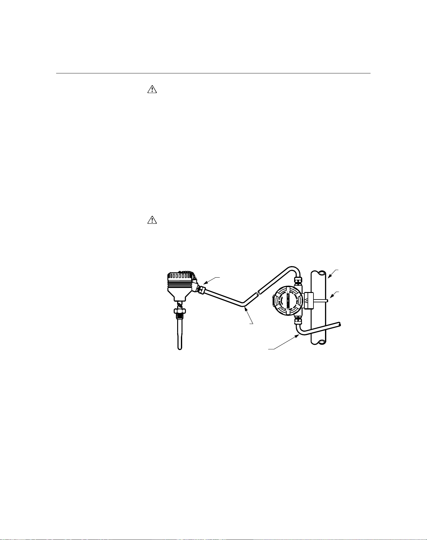
Figure 2-5. Typical European
Process Mounting
Configuration.
1. Mount the thermowell to the pipe or the process container wall. Install
and tighten thermowells and sensors. Apply pressure and perform a leak
check before starting the process.
2. Attach a connection head to the thermowell.
3. Insert the sensor into the thermowell and wire it to the connection head.
The wiring diagram is located on the inside of the connection head.
4. Mount the transmitter to a 2-inch (50 mm) pipe or a suitable panel using
one of the optional mounting brackets. The B4 bracket is shown in
Figure 2-5.
5. Attach cable glands to the shielded cable running from the connection
head to the transmitter conduit entry.
6. Run the shielded cable from the opposite conduit entry on the transmitter
back to the control room.
7. Insert the shielded cable leads through the cable entries into the
connection head and the transmitter. Connect and tighten the cable
glands.
8. Connect the shielded cable leads to the connection head terminals
(located inside of the connection head) and the sensor wiring terminals
(located inside of the transmitter housing). Avoid contact with the leads
and the terminals.
2-inch
Cable
Gland
Pipe
B4
Mounting
Bracket
Shielded Cable from
Sensor to Transmitter
Shielded Cable
from Transmitter
to Control Room
644-0000B05B
2-7
Page 22
Rosemount 3144P
Reference Manual
00809-0100-4021, Rev DA
November 2004
In Conjunction with a
Rosemount 333 HART
Tri-Loop (HART / 4–20
mA only)
Figure 2-6. HART Tri-Loop
Installation Flowchart
(1)
START
HERE
Use the dual-sensor option 3144P transmitter that is operating with two
sensors in conjunction with a 333 HART Tri-Loop
®
HART-to-Analog Signal
Converter to acquire an independent 4–20 mA analog output signal for each
sensor input. The 3144P transmitter can be configured to output four of the six
following digital process variables:
•Sensor 1
•Sensor 2
• Differential temperature
• Average temperature
• First good temperature,
• Transmitter terminal temperature.
The HART Tri-Loop reads the digital signal and outputs any or all of these
variables into as many as three separate 4–20 mA analog channels.
Refer to Figure 2-6 for basic installation information. Refer to the 333 HART
Tri-Loop HART-to-Analog Signal Converter Reference Manual (document
number 00809-0100-4754) for complete installation information.
INSTALL THE
TRI-LOOP
COMMISSION
THE TRI-LOOP
Install the
3144P
No
Unpack the
Tri-Loop
Review the
Tri-Loop
Reference
Manual
3144P
Installed?
Yes
Set the 3144P
Burst
Command
Order
Set the 3144P
to Burst HART
Command 3
Review
Tri-Loop
Installation
Considerations
Mount the
Tri-Loop to a
DIN Rail
Run Wires from
3144P to Burst
Input Terminals
Install Channel
1 Wires from
Tri-Loop to
Control Room
OPTIONAL:
Install Channel
2 Wires from
Tri-Loop to
Control Room
OPTIONAL:
Install Channel
3 Wires from
Tri-Loop to
Control Room
Configure the
Tri-Loop to
Receive 3144P
Burst
Commands
Pass System
Tes t?
Yes
DONE
No
Refer to the
HART Tri-Loop
Reference
Manual
(1) See “Use with the HART Tri-Loop” on page 3-24 for configuration information.
2-8
Page 23

Reference Manual
00809-0100-4021, Rev DA
November 2004
Rosemount 3144P
LCD Display Transmitters ordered with the LCD display option (code M5) are shipped with
the LCD display installed. After-market installation of the LCD display on a
conventional 3144P transmitter requires a small instrument screwdriver and
the LCD display kit, which includes:
• LCD display assembly
• Extended cover with cover O-ring in place
• Captive screws (quantity 2)
• 10-pin interconnection header
Use the following procedure to install the LCD display. Once the LCD display
is installed, configure the transmitter to recognize the meter option. Refer to
“LCD Meter Options” on page 3-19 (HART) or “LCD Transducer Block” on
page 4-11 (F
1. If the transmitter is installed in a loop, set the loop to manual (HART) /
out-of-service (F
2. Remove the housing cover from the electronics side of the transmitter.
Do not remove the transmitter covers in explosive atmospheres if the
circuit is live.
3. Ensure that the transmitter write protect switch is set to the Off position.
If transmitter security is On, then you will not be able to configure the
transmitter to recognize the LCD display. If security On is desired, first
configure the transmitter for the LCD display and then install the meter.
4. Insert the interconnection header in the 10-pin socket on the face of the
electronics module. Insert the pins into the electronics LCD interface.
5. Orient the meter. The meter can be rotated in 90-degree increments for
easy viewing. Position one of the four 10-pin sockets on the back of the
meter to accept the interconnection header.
6. Attach the LCD display assembly to the interconnection pins. Thread and
tighten the LCD display screws into the holes on the electronics module.
7. Attach the extended cover; tighten at least one-third turn after the O-ring
contacts the transmitter housing. Both transmitter covers must be fully
engaged to meet explosion proof requirements.
8. Apply power and set the loop to automatic (HART) / in-service
(F
OUNDATION fieldbus).
OUNDATION Fieldbus) mode and disconnect the power.
OUNDATION Fieldbus) mode.
NOTE
Observe the following LCD display temperature limits:
Operating:–4 to 185 °F (–20 to 85 °C)
Storage:–50 to 185 °F (–45 to 85 °C)
2-9
Page 24
Rosemount 3144P
Reference Manual
00809-0100-4021, Rev DA
November 2004
Multichannel Installation
(HART / 4–20 mA only)
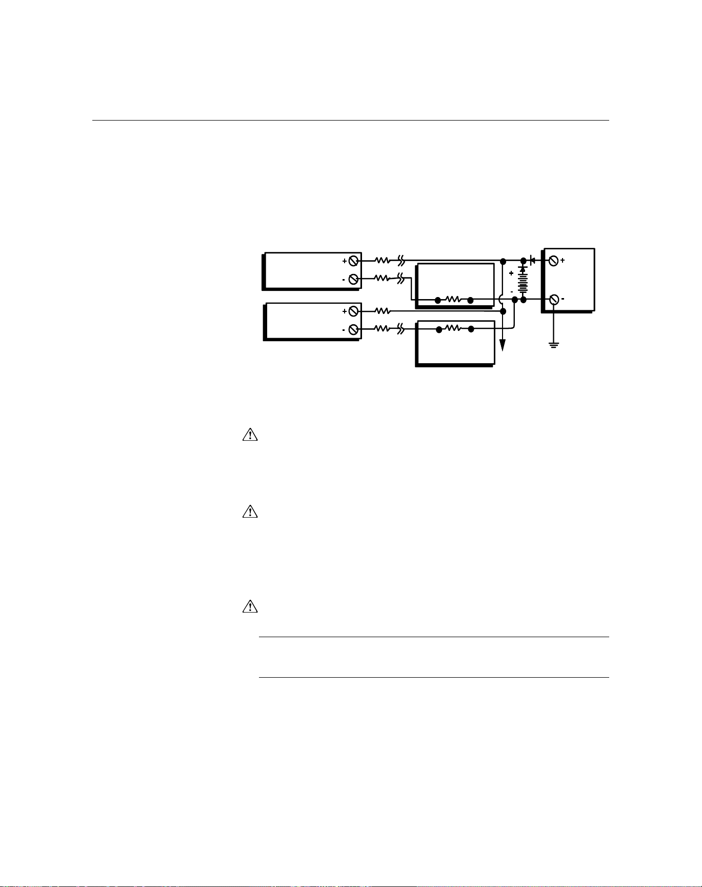
You can connect several transmitters to a single master power supply (see
Figure 2-7). In this case, the system may be grounded only at the negative
power supply terminal. In multichannel installations where several
transmitters depend on one power supply and the loss of all transmitters
would cause operational problems, consider an uninterrupted power supply or
a back-up battery. The diodes shown in Figure 2-7 prevent unwanted
charging or discharging of the back-up battery.
Figure 2-7. Multichannel
Installations.
Transmitter
No. 1
Transmitter
No. 2
Between 250 and 1100 Ω
If No Load Resistor
WIRING
HART / 4–20 mA Field Wiring
All power to the transmitter is supplied over the signal wiring. Signal wiring
does not need to be shielded, but twisted pairs should be used for the best
results. Do not run unshielded signal wiring in conduit or open trays with
power wiring or near heavy electrical equipment. High voltage may be present
on the leads and may cause electrical shock. To wire the transmitter for
power, follow the steps below.
R
Lead
R
R
Lead
Lead
Readout or
Controller No. 1
Readout or
Controller No. 2
Battery
Backup
To Additional
Transmitters
dc
Power
Supply
3044-0131A
1. Remove the transmitter covers. Do not remove the transmitter covers in
an explosive atmosphere when the circuit is live.
2. Connect the positive power lead to the terminal marked “+” and the
negative power lead to the terminal marked “–” as shown in Figure 2-8.
Crimped lugs are recommended when wiring to screw terminals.
3. Tighten the terminal screws to ensure that good contact is made. No
additional power wiring is required.
4. Replace the transmitter covers. Both transmitter covers must be fully
engaged to meet explosion-proof requirements.
NOTE
Do not apply high voltage (e.g., ac line voltage) to the transmitter terminals.
Abnormally high voltage can damage the unit.
2-10
Page 25
Reference Manual
00809-0100-4021, Rev DA
November 2004
Rosemount 3144P
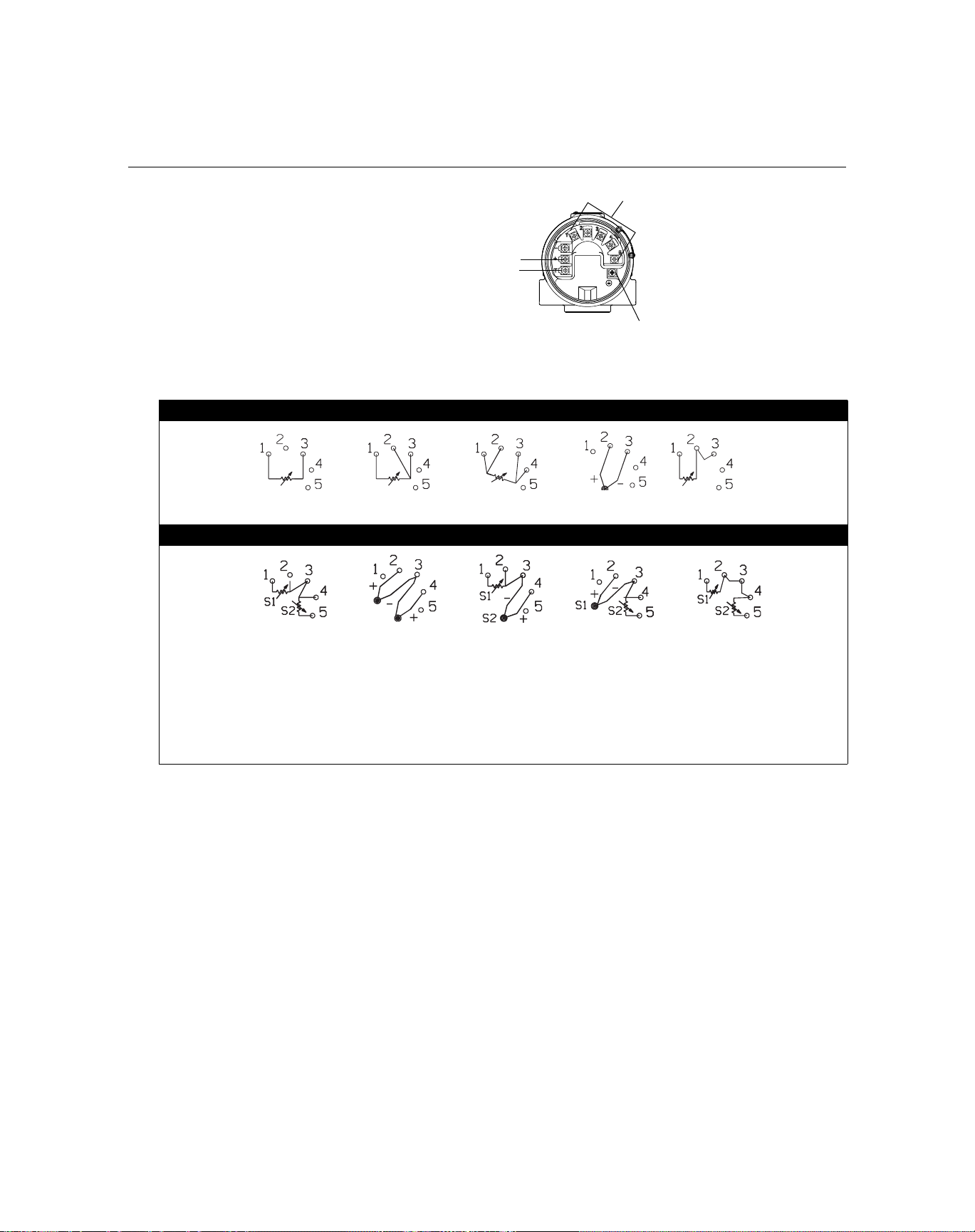
Figure 2-8. Transmitter Terminal
Block
Figure 2-9. HART / 4–20 mA
Wiring Diagram
2-wire RTD
and Ohms
W
R
∆T/Hot Backup/Dual
Sensor with
2 RTDs
W & G
***
**
3-wire RTD
and Ohms**
G
B
Thermocouples
“+”
Tes t
3144P Single-Sensor Connections Diagram
4-wire RTD
and Ohms
3144P Dual-Sensor Connections Diagram
∆T/Hot
Backup/Dual
Sensor with 2
∆T/Hot
Backup/Dual
Sensor with
RTDs/
Thermocouples
Sensor with RTDs/
**
Sensor Terminals (1 – 5)
Ground
T/Cs and
Millivolts
Backup/Dual
Thermocouples
Compensation Loop*
∆T/Hot
RTD with
∆T/Hot Backup/Dual
Sensor with 2 RTDs
with Compensation
** **
Loop
* Transmitter must be configured for a 3-wire RTD in order to recognize an RTD with a compensation loop.
** Emerson Process Management provides 4-wire sensors for all single-element RTDs. You can use these RTDs in 3-wire configurations by
leaving the unneeded leads disconnected and insulated with electrical tape.
*** Typical wiring configuration of a Rosemount dual-element RTD is shown (R=Red, W=White, G=Green, B=Black)
2-11
Page 26

Rosemount 3144P
Reference Manual
00809-0100-4021, Rev DA
November 2004
Power/Current Loop Connections
Use copper wire of a sufficient size to ensure that the voltage across the
transmitter power terminals does not go below 12.0 V dc.
1. Connect the current signal leads as shown in Figure 2-10.
2. Recheck the polarity and correctness of connections.
3. Turn the power ON.
For information about multichannel installations, refer to page 2-17.
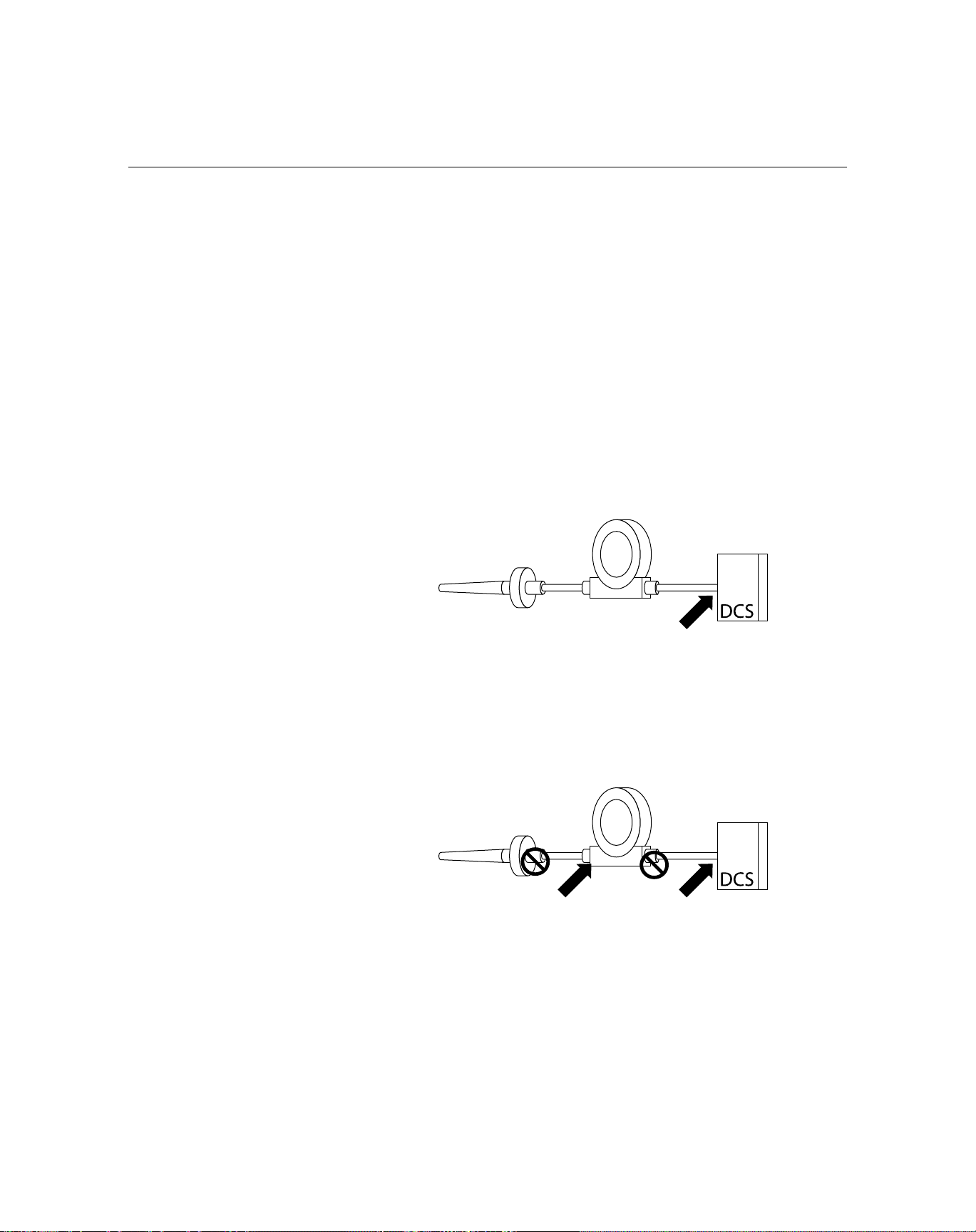
NOTE
Do not connect the power/signal wiring to the test terminal. The voltage
present on the power/signal leads may burn out the reverse-polarity
protection diode that is built into the test terminal. If the test terminal’s reverse
polarity protection diode is burned out by the incorrect power/signal wiring, the
transmitter can still be operated by jumping the current from the test terminal
to the “–” terminal. See “Test Terminal” on page 4-3 for use of the terminal.
Figure 2-10. m Connecting
a Communicator to a
Transmitter Loop (HART/ 4–20
mA).
Power/Signal Terminals
The signal wire may be grounded at
any point or left ungrounded.
250 ≤ R
or*
AMS software or a 375 Field Communicator can be connected at any termination
point in the signal loop. The signal loop must have between 250 and 1100 ohms
load for communications.
≤ 1100
L
Power
Supply
3144-0000A04A
2-12
Page 27
Reference Manual
00809-0100-4021, Rev DA
November 2004
FOUNDATION Fieldbus
Rosemount 3144P
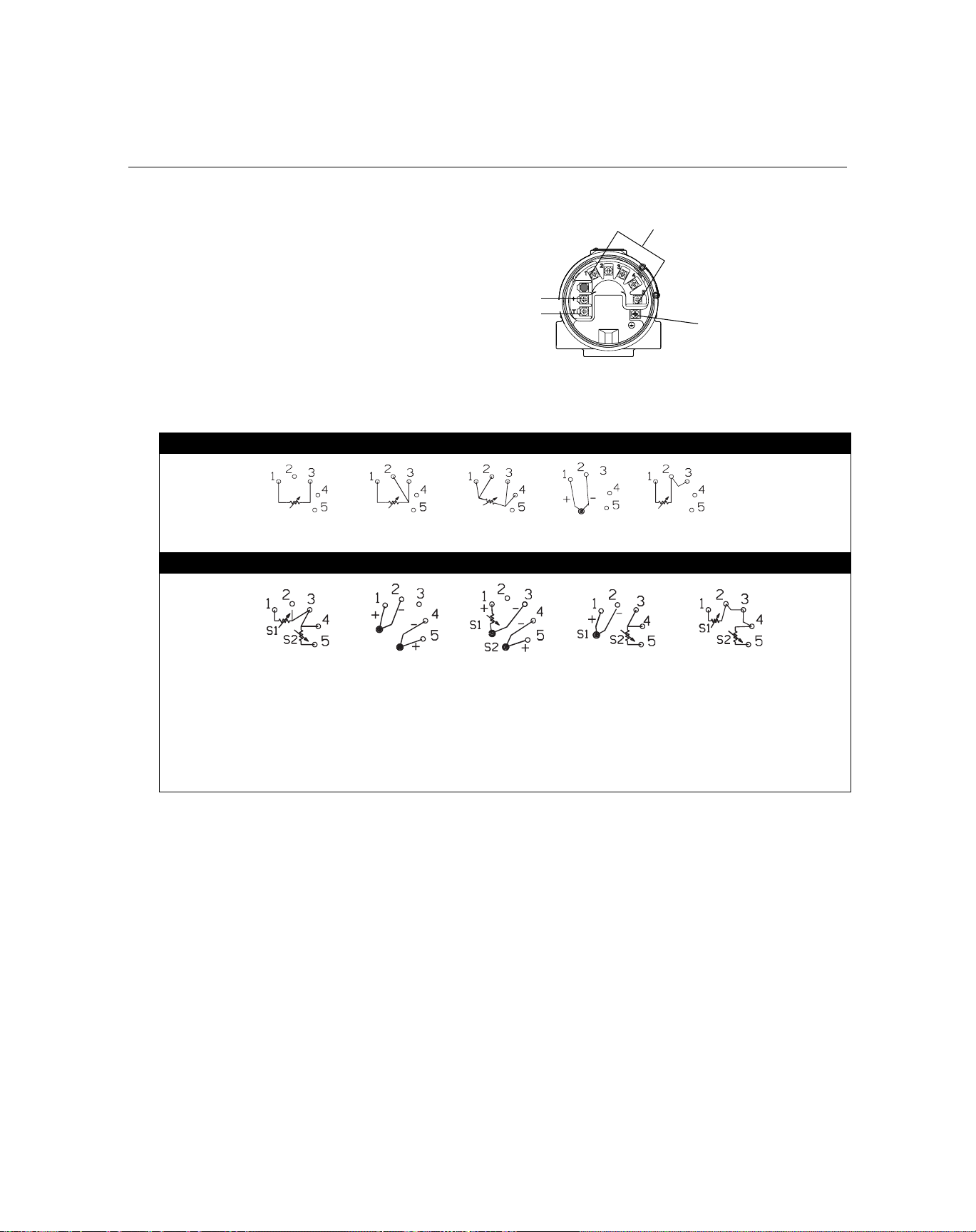
Figure 2-11. Transmitter
Terminal Block
Figure 2-12. F
OUNDATION
Fieldbus Field Wiring Diagram
2-wire RTD
and Ohms
W
R
W & G
G
B
Power Terminals
3144P Single-Sensor Connections Diagram
3-wire RTD
and Ohms**
3144P Dual-Sensor Connections Diagram
4-wire RTD
and Ohms
T/Cs and
Millivolts
Sensor Terminals (1 – 5)
Ground
RTD with
Compensation Loop*
∆T/Hot
Backup/Dual
Sensor with 2
RTDs
* Transmitter must be configured for a 3-wire RTD in order to recognize an RTD with a compensation loop.
** Emerson Process Management provides 4-wire sensors for all single-element RTDs. You can use these RTDs in 3-wire configurations by leaving
the unneeded leads disconnected and insulated with electrical tape.
*** Typical wiring configuration of a Rosemount dual-element RTD is shown (R=Red, W=White, G=Green, B=Black)
∆T/Hot Backup/Dual
Sensor with 2
Thermocouples
**
***
∆T/Hot
Backup/Dual
Sensor with RTDs/
Thermocouples
**
∆T/Hot
Backup/Dual
Sensor with RTDs/
Thermocouples
∆T/Hot Backup/Dual
Sensor with 2 RTDs
with Compensation
**
Loop
**
2-13
Page 28

Reference Manual
00809-0100-4021, Rev DA
Rosemount 3144P
November 2004
Sensor Connections Figure 2-9 on page 2-11 (HART) and Figure 2-12 on page 2-13 (FOUNDATION
fieldbus) shows the correct sensor wiring connections to the transmitter
sensor terminals. To ensure an adequate sensor connection, anchor the
sensor lead wires beneath the flat washer on the terminal screw. Do not
remove the transmitter cover in explosive atmospheres if the circuit is live.
Both transmitter covers must be fully engaged to meet explosion-proof
requirements. Use extreme caution when making contact with the leads and
terminals.
RTD or Ohm Inputs
If the transmitter is mounted remotely from a 3- or 4-wire RTD, it will operate
within specifications, without recalibration, for lead wire resistances of up to
10 ohms per lead (equivalent to 1,000 feet of 20 AWG wire). In this case, the
leads between the RTD and transmitter should be shielded. If using only two
leads (or a compensation loop lead wire configuration), both RTD leads are in
series with the sensor element, so significant errors can occur if the lead
lengths exceed one foot of 20 AWG wire. For longer runs, attach a third or
fourth lead as described above. To eliminate 2-wire lead resistance error, the
2-wire offset command can be used. This allows the user to input the
measured lead wire resistance, resulting in the transmitter adjusting the
temperature to correct the error.
Thermocouple or Millivolt Inputs
For direct-mount applications, connect the thermocouple directly to the
transmitter. If mounting the transmitter remotely from the sensor, use
appropriate thermocouple extension wire. Make connections for millivolt
inputs with copper wire. Use shielding for long runs of wire.
NOTE
For HART transmitters, the use of two grounded thermocouples with a dual
option 3144P transmitter is not recommended. For applications in which the
use of two thermocouples is desired, connect either two ungrounded
thermocouples, one grounded and one ungrounded thermocouple, or one
dual element thermocouple.
POWER SUPPLY HART
An external power supply is required to operate the 3144P (not included). The
input voltage range of the transmitter is 12 to 42.4 V DC. This is the power
required across the transmitter power terminals. The power terminals are
rated to 42.4 V DC. With 250 ohms of resistance in the loop, the transmitter
will require a minimum of 18.1 V DC for communication.
The power supplied to the transmitter is determined by the total loop
resistance and should not drop below the lift-off voltage. The lift-off voltage is
the minimum supply voltage required for any given total loop resistance. See
Figure 2-13 to determine the required supply voltage. If the power drops
below the lift-off voltage while the transmitter is being configured, the
transmitter may output incorrect information.
2-14
The dc power supply should provide power with less than 2% ripple. The total
resistance load is the sum of the resistance of the signal leads and the load
resistance of any controller, indicator, or related piece of equipment in the
loop. Note that the resistance of intrinsic safety barriers, if used, must be
included.
Page 29

Reference Manual
00809-0100-4021, Rev DA
November 2004
Rosemount 3144P
NOTE
Do not allow the voltage to drop below 12.0 V dc at the transmitter terminals
when changing transmitter configuration parameters, or permanent damage
to the transmitter could result.
Figure 2-13. Load Limits.
Maximum Load = 40.8 X (Supply Voltage - 12.0)
4–20 mA dc
Operating
Region
20 30 40 42.4
12.0
Supply Voltage (V dc)
F
OUNDATION fieldbus
Powered over F
OUNDATION fieldbus with standard fieldbus power supplies.
1240
1100
1000
750
500
Load (Ohms)
250
0
10
The transmitter operates between 9.0 and 32.0 V dc, 11 mA maximum.
Transmitter power terminals are rated to 42.4 VDC.
The power terminals on the 3144P with F
OUNDATION fieldbus are polarity
insensitive.
Surges/Transients The transmitter will withstand electrical transients of the energy level usually
encountered in static discharges or induced switching. However, high-energy
transients, such as those induced in wiring from nearby lightning strikes, can
damage both the transmitter and the sensor.
To protect against high-energy transients, install the integral transient
protection board (option code T1). The integral transient protection board is
available as an ordered option or as an accessory. Refer to “ Transient
Protection (Option Code T1)” on page A-16 for more information.
Grounding Sensor Shielding
The currents in the leads induced by electromagnetic interference can be
reduced by shielding. Shielding carries the current to ground and away from
the leads and electronics. If the ends of the shields are adequately grounded,
little current will actually enter the transmitter.
If the ends of the shield are left ungrounded, a voltage is created between the
shield and the transmitter housing and also between the shield and earth at
the element end. The transmitter may not be able to compensate for this
voltage, causing it to lose communication and/or go into alarm. Instead of the
shield carrying the currents away from the transmitter, the currents will now
flow through the sensor leads into the transmitter circuitry where they will
interfere with the circuit operation.
2-15
Page 30
Rosemount 3144P
Reference Manual
00809-0100-4021, Rev DA
November 2004
Shielding Recommendations
The following are recommended practices are from API Standard 552
(Transmission Standard) section 20.7 and from field and laboratory testing. If
more than one recommendation is given for a sensor type, start with the first
technique shown or the technique that is recommended for the facility by its
installation drawings. If the technique does not eliminate the transmitter
alarms, try another technique. If all techniques unsuccessfully prevent
transmitter alarms due to high EMI, contact a Emerson Process Management
representative.
Ungrounded Thermocouple, mV, and RTD/Ohm Inputs
Option 1: recommended for ungrounded transmitter housing
1. Connect the signal wiring shield to the sensor wiring shield.
2. Ensure the two shields are tied together and electrically isolated from
the transmitter housing.
3. Ground the shield at the power supply end only.
4. Ensure the shield at the sensor is electrically isolated from the
surrounding fixtures that may be grounded.
Sensor Wires
Shield ground point
Connect shields together, electrically isolated from the transmitter
Option 2: recommended for grounded transmitter housing
1. Connect the sensor wiring shield to the transmitter housing, provided
the transmitter housing is grounded (see "Transmitter Housing").
2. Ensure the shield at the sensor end is electrically isolated from
surrounding fixtures that may be grounded.
3. Ground the signal wiring shield at the power supply end.
Sensor Wires
Shield ground points
2-16
Page 31

Reference Manual
00809-0100-4021, Rev DA
November 2004
Rosemount 3144P
Option 3
1. Ground the sensor wiring shield at the sensor, if possible.
2. Ensure the sensor wiring and signal wiring shields are electrically
isolated form the transmitter housing and other fixtures that may
be grounded.
3. Ground the signal wiring shield at the power supply end.
Sensor Wires
Shield ground points
Grounded Thermocouple Inputs
1. Ground the sensor wiring shield at the sensor.
2. Ensure the sensor wiring and signal wiring shields are electrically
isolated form the transmitter housing and other fixtures that may
be grounded.
3. Ground the signal wiring shield at the power supply end.
Sensor Wires
Shield ground points
Transmitter Housing
Ground the transmitter housing in accordance with local electrical
requirements. An internal ground terminal is standard. An optional external
ground lug assembly (Option Code G1) can also be ordered if needed.
Ordering certain hazardous approvals automatically includes an external
ground lug (see Table A-5 on page A-16).
2-17
Page 32

Rosemount 3144P
Reference Manual
00809-0100-4021, Rev DA
November 2004
2-18
Page 33

Reference Manual
00809-0100-4021, Rev DA
November 2004
Rosemount 3144P
Section 3 HART Commissioning
Overview . . . . . . . . . . . . . . . . . . . . . . . . . . . . . . . . . . . . . . . page 3-1
Safety Messages . . . . . . . . . . . . . . . . . . . . . . . . . . . . . . . . . page 3-1
375 Field Communicator . . . . . . . . . . . . . . . . . . . . . . . . . . page 3-2
AMS . . . . . . . . . . . . . . . . . . . . . . . . . . . . . . . . . . . . . . . . . . . page 3-5
Review Configuration Data . . . . . . . . . . . . . . . . . . . . . . . . page 3-5
Check Output . . . . . . . . . . . . . . . . . . . . . . . . . . . . . . . . . . . page 3-6
Configuration . . . . . . . . . . . . . . . . . . . . . . . . . . . . . . . . . . . page 3-6
Device Output Configuration . . . . . . . . . . . . . . . . . . . . . . . page 3-14
Device Information . . . . . . . . . . . . . . . . . . . . . . . . . . . . . . . page 3-18
Measurement Filtering . . . . . . . . . . . . . . . . . . . . . . . . . . . . page 3-19
Diagnostics and Service . . . . . . . . . . . . . . . . . . . . . . . . . . page 3-21
Multidrop Communication . . . . . . . . . . . . . . . . . . . . . . . . . page 3-24
Use with the HART Tri-Loop . . . . . . . . . . . . . . . . . . . . . . . page 3-25
Calibration . . . . . . . . . . . . . . . . . . . . . . . . . . . . . . . . . . . . . . page 3-28
Trim the Transmitter . . . . . . . . . . . . . . . . . . . . . . . . . . . . . . page 3-28
Troubleshooting . . . . . . . . . . . . . . . . . . . . . . . . . . . . . . . . . page 3-35
OVERVIEW This section contains information on commissioning and tasks that should be
performed on the bench prior to installation. This section contains 3144P
HART configuration only. 375 Field Communicator and AMS instructions are
given to perform configuration functions. For additional information, refer to
the HART Communication Reference Manual (document number
00809-0100-4276). AMS help can be found in the AMS on-line guides within
the AMS system.
HART
SAFETY MESSAGES Instructions and procedures in this section may require special precautions to
ensure the safety of the personnel performing the operations. Information that
raises potential safety issues is indicated by a warning symbol ( ). Please
refer to the following safety messages before performing an operation
preceded by this symbol.
Explosions may result in death or serious injury.
• Do not remove the instrument cover in explosive atmospheres when the circuit is
live.
• Before connecting a 375 Field Communicator in an explosive atmosphere, make
sure the instruments in the loop are installed in accordance with intrinsically safe or
non-incendive field wiring practices.
• Both covers must be fully engaged to meet explosion–proof requirements.
Electrical shock could cause death or serious injury. If the sensor is installed in a
high-voltage environment and a fault or installation error occurs, high voltage may be
present on transmitter leads and terminals.
• Use extreme caution when making contact with the leads and terminals.
www.rosemount.com
Page 34

Rosemount 3144P
Reference Manual
00809-0100-4021, Rev DA
November 2004
HART
375 FIELD
COMMUNICATOR
Updating the HART
Communication Software
The Menu Tree and Fast Key sequences use the following device revisions:
• Standard 3144P: Device Revision Dev v3, DD v2
• 3144P SIS: Device Revision Dev v2, DD v1
The 375 Field Communicator exchanges information with the transmitter from
the control room, the instrument site, or any wiring termination point in the
loop. To facilitate communication, connect the Field Communicator in parallel
with the transmitter (see Figure 2-10). Use the loop connection ports on the
top of the Field Communicator. The connections are non-polarized. Do not
make connections to the NiCad recharger jack in explosive atmospheres.
Before connecting the Field Communicator in an explosive atmosphere, make
sure the instruments in the loop are installed in accordance with intrinsically
safe or non-incendive field wiring practices
The 375 Field Communicator software may need to be updated to take
advantage of the additional features available in the 3144P (field device
revision 3). Perform the following steps to determine if an upgrade is
necessary.
1. Choose “Rosemount” from the list of manufacturers and “3144 Temp”
from the list of models.
2. If the Fld Dev Rev choices include “Dev v3, DD v2,” an upgrade is not
required. If the only choice is “Dev v1” or “Dev v2” (with any DD version),
then the communicator should be upgraded. The 3144P SIS Safety
Certified transmitters requires Device Revision Dev v2, DD v1.
NOTE
If communication is initiated with an improved 3144P using a communicator
that only has a previous version of the transmitter device descriptors (DDs),
the communicator will display the following message:
NOTICE: Upgrade to the 375 software to access new XMTR functions.
Continue with old description?
Select YES: the communicator will communicate properly with the transmitter
using the existing transmitter DDs. However, new software features of the DD
in the communicator will not be accessible. I
Select NO: the communicator will default to a generic transmitter functionality.
If YES is selected when the transmitter is already configured to utilize the new
features of the improved transmitters (such as Dual Input configuration or one
of the added sensor input types–DIN Type L or DIN Type U), the user will
experience trouble communicating with the transmitter and will be prompted
to turn the communicator off. To prevent this from happening, either upgrade
the communicator to the latest DD or answer NO to the question above and
default to the generic transmitter functionality.
To see a list of enhancements included in the improved transmitters, see
“Rosemount 3144P and Rosemount 3144 / 3244MV Differences” on
page 1-6.
3-2
Page 35

Reference Manual
00809-0100-4021, Rev DA
November 2004
Rosemount 3144P
Menu Tree Figure 3-1 displays a complete 3144P menu tree for use with the 375 Field
Communicator. Options listed in bold type indicate that a selection provides
other options.
For 3144P SIS Safety Certified transmitter, see “3144P SIS Safety Certified
Menu Tree” on page 6-4.
Figure 3-1. 3144P Menu Tree
Online Menu
1. DEVICE SETUP
2. PV is
3. PV
4. AO
5. % RNGE
6. PV LRV
7. PV URV
NOTE
The review menu
lists all of the
information
stored in the
3144P. This
includes device
information,
measuring
element, output
configuration, and
software revision.
1. PROCESS
VARIABLE
2. DIAGNOSTICS
AND SERVICE
3. CONFIGURATION
4. REVIEW
1. Device Variables
2. PV is
3. PV Digital
4. PV AO
5. PV% rnge
6. PV LRV
7. PV URV
8. PV LSL
9. PV USL
10.PV Damp
1. TEST DEVICE
2. CALIBRATION
1. VARIABLE
MAPPING
2. SENSOR
CONFIGURATION
3. DUAL-SENSOR
CONFIGURATION
4. DEV OUTPUT
CONFIGURATION
5. DEVICE
INFORMATION
6. MEASUREMENT
FILTERING
1. Revision #s
2. Dynamic Variables
3. Device Variables
4. Sensor Variables
5. Other Variables
1. Snsr 1
2. Snsr 2
3. Terminal
4. Diff.
5. Avg
6. First Good
1. Loop Test
2. Self test
3. Master Reset
4. Status
1. SNSR TRIM
2. D/A trim
3. Scaled D/A trim
1. PV is
2. SV is
3. TV is
4. QV is
5. Variable re-map
1. Chng Type/Conn
2. Show Type/Conn
3. Sensor 1 Setup
4. Sensor 2 Setup
5. Ter m Tem p Se tup
1. Diff Config
2. Avg Config
3. First Good Config
4. Config Hot Backup
5. Drift Alert
1. PV RANGE
VAL UES
2. ALARM
SATURATION
3. HART OUTPUT
4. LCD DISPLAY
OPTIONS
1. Tag
2. Date
3. Descriptor
4. Message
5. Final Assembly number
1. Universal rev
2. Field Dev Rev
3. Software Rev
4. Hardware
1. Review Snsr1
2. Review Snsr2
1. Microboard
2. A/D ASIC
3. Operation
4. Summary Byte
5. Sensor Information
1. Snsr inp trim
2. Snsr trim-fact
3. Active Calibrator
1. Sensor 1
2. Sensor 2
1. Snsr 2 Units
2. Snsr 2 damp
3. Snsr 2 S/N
4. Snsr 2 LSL
5. Snsr 2 USL
6. 2-Wire Offset
1. Diff Units
2. Diff Damp
3. Diff LSL
4. Diff USL
1. First Good Units
2. First Good Damp
3. First Good LSL
4. First Good USL
1. PV LRV
2. PV URV
3. PV Damping
4. PV Units
5. PV LSL
6. PV USL
7. PV Min. Span
1. AO alrm type
2. AO Levels
3. Non-PV Alarms
1. Poll addr
2. Num req preams
3. Burst mode
4. Burst option
1. Meter Configuration
2. Meter Decimal Point
3. Meter Bar Graph
1. 50/60 Hz Filter
2. Intermit Detect
3. Intermit Thresh
4. Open Sensor
Holdoff
1. Review PV
2. Review SV
3. Review TV
4. Review QV
1. Snsr 1 Units
2. Snsr 1 damp
3. Snsr 1 S/N
4. Snsr 1 LSL
5. Snsr 1 USL
6. 2-Wire Offset
1. Terminal Units
2. Terminal Damp
3. Terminal LSL
4. Terminal USL
1. Avg Units
2. Avg Damp
3. Avg LSL
4. Avg USL
1. Drift Alert option
2. Drift Limit
3. Drift Damping
1. Low Alarm
2. High Alarm
3. Low Sat.
4. High Sat.
5. Preset Alarms
1. Sensor 1
2. Sensor 2
3. Ter m Tem p
4. Differential Temp
5. Average Temp
6. First Good
HART
3-3
Page 36

Reference Manual
00809-0100-4021, Rev DA
Rosemount 3144P
November 2004
Fast Key Sequences Fast key sequences are listed below for common 3144P transmitter functions.
HART
NOTE:
The fast key sequences assume that “Device Revision Dev v3, DD v2 is being
used. Table 3-1 provides alphabetical function lists for all Field Communicator
tasks as well as their corresponding fast key sequences.
For 3144P SIS Safety Certified transmitter, see “3144P SIS Fast Key
Sequences” on page 6-5.
Table 3-1. Fast Key Sequence
Function HART Fast Keys Function HART Fast Keys
Active Calibrator 1, 2, 2, 1, 3 Open Sensor Holdoff 1, 3, 6, 4
Alarm Values 1, 3, 4, 2, 1 Percent Range 1, 1, 5
Analog Output 1, 1, 4 Poll Address 1, 3, 4, 3, 1
Average Temperature Setup 1, 3, 3, 2 Process Temperature 1, 1
Average Temperature Configuration 1, 3, 3, 2 Process Variables 1, 1
Burst Mode 1, 3, 4, 3, 3 Range Values 1, 3, 4, 1
Burst Option 1, 3, 4, 3, 4 Review 1, 4
Calibration 1, 2, 2 Scaled D/A Trim 1, 2, 2, 3
Configure Hot Backup 1, 3, 3, 4 Sensor 1 Configuration 1, 3, 2, 3
Configuration 1, 3 Sensor 2 Configuration 1, 3, 2, 4
D/A Trim 1, 2, 2, 2 Sensor Limits 1, 3, 2, 2
Damping Values 1, 3, 4, 1, 3 Sensor 1 Serial Number 1, 3, 2, 3, 3
Date 1, 3, 5, 2 Sensor 2 Serial Number 1, 3, 2, 4, 3
Descriptor 1, 3, 5, 3 Sensor 1 Setup 1, 3, 2, 3
Device Information 1, 3, 5 Sensor 2 Setup 1, 3, 2, 4
Diagnostics and Service 1, 2 Sensor Trim 1, 2, 2, 1, 1
Differential Temperature Setup 1, 3, 3, 1 Sensor Type 1, 3, 2, 1
Differential Temperature Configuration 1, 3, 3, 1 Sensor 1 Unit 1, 3, 2, 3, 1
Drift Alert 1, 3, 3, 5 Sensor 2 Unit 1, 3, 2, 4, 1
Filter 50/60 Hz 1, 3, 6, 1 Software Revision 1, 4, 1
First Good Temperature Setup 1, 3, 3, 3 Status 1, 2, 1, 4
First Good Temperature Configuration 1, 3, 3, 3 Ta g 1, 3, 5, 1
Hardware Revision 1, 4, 1 Terminal Temperature Setup 1, 3, 2, 5
Hart Output 1, 3, 4, 3 Test Device 1, 2, 1
Intermittent Sensor Detect 1, 3, 6, 2 Transmitter-Sensor Matching 1, 3, 2, 1
Intermittent Threshold 1, 3, 6, 3 URV (Upper Range Value) 1, 3, 4, 1, 2
Loop Test 1, 2, 1, 1 USL (Upper Sensor Limit) 1, 3, 4, 1, 6
LRV (Lower Range Value) 1, 3, 4, 1, 1 Variable Mapping 1, 3, 1
LSL (Lower Sensor Limit) 1, 3, 4, 1, 5 Wires 1, 3, 2, 1
Master Reset 1, 2, 1, 3 2-wire Offset Sensor 1 1, 3, 2, 3, 6
Message 1, 3, 5, 4 2-wire Offset Sensor 2 1, 3, 2, 4, 6
Meter Options 1, 3, 4, 4
3-4
Page 37

Reference Manual
00809-0100-4021, Rev DA
November 2004
Rosemount 3144P
AMS One of the key benefits of intelligent devices is the ease of device
configuration. When used with AMS, the 3144P is easy to configure and
provides instant and accurate alerts and alarms. The main configuration
screen of the 3144P is the “Configuration Properties” screen. From this
screen, the transmitter set-up can easily be viewed and edited.
The screens use a color-coding to give visual indication of the transmitter
health and to indicate any changes that may need to be made or written to the
transmitter.
• Gray screens: indicates that all information has been written to the
transmitter
• Yellow on screen: changes have been made in the software but not
sent to the transmitter
• Green on screen: all current changes on screen have been written to
the transmitter
• Red on screen: indicates an alarm or alert that requires immediate
investigation
HART
Apply AMS Changes Changes made in the software must be sent to the transmitter in order for the
changes to take effect in the process.
1. From the bottom of the “Configuration Properties” screen, click Apply.
2. An “Apply Parameter Modification” screen appears, enter desired
information and click OK.
3. After carefully reading the warning provided, select OK.
REVIEW
CONFIGURATION DATA
Before operating the 3144P in an actual installation, review all of the
factory-set configuration data to ensure that it reflects the current application.
Review
HART Fast Keys 1, 4
Review the transmitter configuration parameters set at the factory to ensure
accuracy and compatibility with the particular application. After activating the
Review function, scroll through the data list to check each variable. If changes
to the transmitter configuration data are necessary, refer to “Configuration”
below.
AMS
Right click on the device and select “Configuration Properties” from the
menu. Select the tabs to review the transmitter configuration data.
3-5
Page 38

HART
Reference Manual
00809-0100-4021, Rev DA
Rosemount 3144P
November 2004
CHECK OUTPUT Before performing other transmitter online operations, review the
configuration of the 3144P digital output parameters to ensure that the
transmitter is operating properly.
Process Variables
HART Fast Keys 1, 1
The 3144P process variables provide the transmitter output. The PROCESS
VARIABLE menu displays the process variables, including sensed
temperature, percent range, and analog output. These process variables are
continuously updated. The primary variable is 4–20 mA analog signal.
AMS
Right click on the device and select “Configuration Properties” from the
menu. Select the Analog Output tab to review the transmitter Analog
Output Range.
CONFIGURATION The 3144P must be configured for certain basic variables to operate. In many
cases, these variables are pre-configured at the factory. Configuration may be
required if the configuration variables need revision.
Variable Mapping
HART Fast Keys 1, 3, 1
The Variable Mapping menu displays the sequence of the process variables.
Select 5 Variable Re-Map to change this configuration. With the 3144P single
sensor input configuration, screens follow that allow selection of the primary
variable (PV) and the secondary variable (SV). When the Select PV screen
appears Snsr 1 or terminal temperature must be selected.
With the 3144P dual-sensor option configuration, screens follow that allows
selection of the primary variable (PV), secondary variable (SV), tertiary
variable (TV), and quaternary variable (QV). Variable choices are Sensor 1,
Sensor 2, Differential Temperature, Average Temperature, First-Good
Temperature, Terminal Temperature, and Not Used. The primary variable is
the 4–20 mA analog signal.
AMS
Right click on the device and select “Configuration Properties” from the
menu. Select the Analog Output tab to review the Mapped Variable
Output.
Apply changes made (see “Apply AMS Changes” on page 3-5).
Sensor Configuration
HART Fast Keys 1, 3, 2
Sensor configuration contains information for updating the sensor type,
connections, units, and damping.
3-6
Page 39

Reference Manual
00809-0100-4021, Rev DA
November 2004
Rosemount 3144P
Change Type and Connections
HART Fast Keys 1, 3, 2, 1
The Connections command allows the user to select the sensor type and the
number of sensor wires to be connected. Select from the following sensor
types:
• 2-, 3-, or 4-wire Pt 100, Pt 200, Pt 500, Pt 1000
platinum RTDs (α = 0.00385 Ω/Ω/°C)
• 2-, 3-, or 4-wire Pt 100 (α = 0.003916 Ω/Ω/°C)
• 2-, 3-, or 4-wire Ni 120 nickel RTDs
• 2-, 3-, or 4-wire Cu 10 RTDs
• IEC/NIST/DIN Type B, E, J, K, R, S, T thermocouples
• DIN type L, U thermocouples
• ASTM Type W5Re/W26Re thermocouple
• –10 to 100 millivolts
• 2-, 3-, or 4-wire 0 to 2000 ohms
Contact a Emerson Process Management representative for information on
the temperature sensors, thermowells, and accessory mounting hardware
that is available through Emerson Process Management.
HART
AMS
Right click on the device and select “Configuration.” Select “Sensor
Connections,” then “Change type and connection.” The wizard will walk
through the screens.
Output Units
HART Fast Keys 1, 3, 2, 3 or 4
The Snsr 1 Unit and Snsr 2 Unit commands set the desired primary variable
units. Set the transmitter output to one of the following engineering units:
• Degrees Celsius
• Degrees Fahrenheit
• Degrees Rankine
•Kelvin
•Ohms
• Millivolts
AMS
Right click on the device and select “Configuration Properties” from the
menu. Select the Sensor 1 (or Sensor 2) tab to configure the Sensor
Output Units. Set the units to the desired output.
Apply changes made (see “Apply AMS Changes” on page 3-5).
3-7
Page 40

Rosemount 3144P
Reference Manual
00809-0100-4021, Rev DA
November 2004
Sensor 1 Serial Number
HART Fast Keys 1, 3, 2, 3, 3
HART
The Sensor 1 S/N variable provides a location to list the serial number of the
attached sensor. It is useful for identifying sensors and tracking sensor
calibration information.
AMS
Right click on the device and select “Configuration Properties” from the
menu. Select the Sensor 1 tab to configure the Sensor 1 Serial #.
Apply changes made (see “Apply AMS Changes” on page 3-5).
Sensor 2 Serial Number
HART Fast Keys 1, 3, 2, 4, 3
The Sensor 2 S/N variable provides a location to list the serial number of a
second sensor.
AMS
Right click on the device and select “Configuration Properties” from the
menu. Select the Sensor 2 tab to configure the Sensor 2 Serial #.
Apply changes made (see “Apply AMS Changes” on page 3-5).
2-Wire RTD Offset
HART Fast Keys 1, 3, 2, 3, 6
The 2-wire Offset command allows the user to input the measured lead wire
resistance, which will result in the transmitter adjusting its temperature
measurement to correct the error caused by this resistance. Due to a lack of
lead wire compensation within the RTD, temperature measurements made
with a 2-wire RTD are often inaccurate.
To utilize this feature perform the following steps:
1. Measure the lead wire resistance of both RTD leads after installing the
2-wire RTD and the 3144P.
2. From the HOME screen, select 1 Device Setup, 3 Configuration,
2 Sensor Configuration, 3 Sensor 1 Setup, 6 2-Wire Offset.
3. Enter the total measured resistance of the two RTD leads at the 2-Wire
Offset prompt. Enter this resistance as a negative (–) value to ensure
proper adjustment.The transmitter then adjusts its temperature
measurement to correct the error caused by lead wire resistance.
4. Repeat Steps 1 through 3 for sensor 2, selecting 1 Device Setup, 3
Configuration, 2 Sensor Configuration, 4 Sensor 2 Setup, 6 2-Wire
Offset.
AMS
Right click on the device and select “Configuration Properties” from the
menu. Select the Sensor 1 (or Sensor 2) tab to configure the 2 Wire Offset.
Apply changes made (see “Apply AMS Changes” on page 3-5).
3-8
Page 41

Reference Manual
00809-0100-4021, Rev DA
November 2004
Rosemount 3144P
Termi n a l Te m perature
HART Fast Keys 1, 3, 2, 5
The Term i n al Tem p command sets the terminal temperature units to indicate
the temperature at the transmitter terminals.
AMS
Right click on the device and select “Configuration Properties” from the
menu. Select the Electronics tab to configure the Terminal Temperature. In
the Terminal Temperature box, Set the Terminal Units to the desired
output.
Apply changes made (see “Apply AMS Changes” on page 3-5).
Dual-Sensor Configuration
HART Fast Keys 1, 3, 3
Dual-sensor configuration allows configuration of the functions that can be
used with a dual-sensor configured transmitter. This includes Differential
Temperature, Average Temperature, First Good Temperature, Hot Backup,
and Sensor Drift Alert.
HART
Differential Temperature
HART Fast Keys 1, 3, 1, 5, 3
The 3144P configured for a dual-sensor can accept any two inputs and
display the differential temperature between them. Use the following
procedure to configure the transmitter to measure differential temperature.
First, configure Sensor 1 and Sensor 2 appropriately. Select 1 Device
Setup, 3 Configuration, 2 Sensor Configuration, 1 Change type/conn to set
the sensor type and number of wires for Sensor 1. Repeat for Sensor 2.
NOTE
This procedure reports the differential temperature as the primary variable
analog signal. If this is not necessary, assign differential temperature to the
secondary, tertiary, or quaternary variable.
1. From the HOME screen, select 1 Device Setup, 3 Configuration, 1
Variable Mapping, 5 Variable Re-Map to prepare to set the transmitter
to display differential temperature. Set the control loop to manual and
select OK.
2. Select 3Diff from the Primary Variable (PV) menu.
3. Select three of the five variables (average temperature, sensor 1, sensor
2, First-Good, and terminal temperature) for the Secondary Variable
(SV), Tertiary Variable (TV), and Quaternary Variable (QV).
NOTE
The transmitter determines the differential temperature by subtracting
Sensor 2 from Sensor 1 (S1 – S2). Ensure that this order of subtraction is
consistent with the desired reading for the application. Refer to Figure 2-12 on
page 2-16, or inside the transmitter terminal-side cover for sensor wiring
diagrams.
3-9
Page 42

HART
Rosemount 3144P
Reference Manual
00809-0100-4021, Rev DA
November 2004
4. Select OK after verifying the variable settings from the variable mapping
menu.
5. Select OK to return the control loop to automatic control.
6. Select HOME to return to the Online menu.
7. Select 1 Device Setup, 3 Configuration, 3 Dual-sensor configuration, 1
Differential Config, 1 Differential Units to set the desired differential units.
8. Select HOME to return to the Home screen.
If you are using a LCD display for local indication, configure the meter to
read the appropriate variables using the “ LCD Display Options” on
page 3-17.
AMS
For AMS, configure each sensor as indicated above.
Right click on the device and select “Configuration Properties” from the
menu. Select the Dual Sensor tab to configure the Differential
Temperature.In the Differential Temperature box, Set the Diff Units to the
desired output. Set damping if applicable.
Apply changes made (see “Apply AMS Changes” on page 3-5).
Average Temperature
HART Fast Keys 1, 3, 1, 5, 4
The 3144P transmitter configured for dual-sensors can output and display
the average temperature of any two inputs. Use the following procedure to
configure the transmitter to measure the average temperature.
First, configure Sensor 1 and Sensor 2 appropriately. Select 1 Device
Setup, 3 Configuration, 2 Sensor Configuration, 1 Change Type and Conn.
to set the sensor type and number of wires for Sensor 1. Repeat for
Sensor 2.
NOTE
This procedure configures the average temperature as the primary variable
analog signal. If this is not necessary, assign the average temperature to the
secondary, tertiary, or quaternary variable.
1. From the Home screen, select 1 Device Setup, 3 Configuration, 1
Variable Mapping, 5 Variable Re-map to set the transmitter to display the
average temperature. Set the control loop to manual and select OK.
2. Select 4 Sensor Average from the Primary Variable (PV) menu.
3. Select three of the five variables (differential temperature, sensor 1,
sensor 2, First-Good, and terminal temperature) for the Secondary
Variable (SV), Tertiary Variable (TV), and Quaternary Variable (QV).
4. Select OK after verifying the variable settings in variable mapping menu.
5. Select OK to return the control loop to automatic control.
6. Select HOME to return to the Online menu.
7. Select 1 Device Setup, 3 Configuration, 3 dual sensor configuration, 2
average, 1 avg units to set the desired average temperature units.
8. Select HOME to return to the Home screen.
If using a LCD display, configure it to read the appropriate variables using
“ LCD Display Options” on page 3-17.
3-10
Page 43

Reference Manual
00809-0100-4021, Rev DA
November 2004
Rosemount 3144P
NOTE
If Sensor 1 and/or Sensor 2 should fail while PV is configured for average
temperature and Hot Backup is not enabled, the transmitter will go into alarm.
For this reason, when PV is Sensor Average it is recommended that Hot
Backup be enabled when dual-element sensors are used or when two
temperature measurements are taken from the same point in the process. If a
sensor failure occurs when Hot Backup is enabled while PV is Sensor
Average, three scenarios could result:
• If Sensor 1 fails, the average will only be reading from Sensor 2, the
working sensor.
• If Sensor 2 fails, the average will only be reading from Sensor 1, the
working sensor.
• If both sensors fail simultaneously, the transmitter will go into alarm and
the status available (via HART) states that both Sensor 1 and Sensor 2
have failed.
In the first two scenarios, where Hot Backup is enabled with PV set to Sensor
Average, the 4-20 mA signal is not disrupted and the status available to the
control system (via HART) specifies which sensor has failed.
HART
AMS
For AMS, configure each sensor as indicated above.
Right click on the device and select “Configuration Properties” from the
menu. Select the Dual Sensor tab to configure the Average
Temperature.In the Average Temperature box, Set the Ave Units to the
desired output. Set damping if applicable.
Apply changes made (see “Apply AMS Changes” on page 3-5).
First-Good Configuration
HART Fast Keys 1, 3, 1, 5, 5
The First Good device variable is useful for applications in which
dual-sensors (or a single dual element sensor) are used in a single
process. The first good variable will report the Sensor 1 value, unless
Sensor 1 fails. When Sensor 1 fails, the Sensor 2 value will be reported as
the first good variable. Once the first good variable has switched to Sensor
2, it will not revert back to Sensor 1 until a master reset occurs or
“Suspend Non-PV alarms” is disabled. When the PV is mapped to first
good and either Sensor 1 or Sensor 2 fails, the analog output will go to the
alarm level, but the digital PV value read through the HART interface will
still report the proper first good sensor value.
If it is desired that the transmitter not go into analog output alarm while
having the PV mapped to first good and Sensor 1 fails, enable “Suspend
Non-PV Alarm” mode. This combination will prevent the analog output
from going to the alarm level unless BOTH sensors fail.
AMS
For AMS, configure each sensor as indicated above.
Right click on the device and select “Configuration Properties” from the
menu. Select the Dual Sensor tab to configure the 1st Good. In the 1st
Good box, set the 1st Good Units to the desired output. Set damping if
applicable.
3-11
Page 44

HART
Rosemount 3144P
Reference Manual
00809-0100-4021, Rev DA
November 2004
Apply changes made (see “Apply AMS Changes” on page 3-5).
Hot Backup Configuration
HART Fast Keys 1, 3, 3, 4
The Config Hot BU command configures the transmitter to automatically
use Sensor 2 as the primary sensor if Sensor 1 fails. With Hot Backup
enabled, the primary variable (PV) must either be First Good or Sensor
Average (see “Average Temperature” on page 3-10 for details on using
Hot Backup when PV is Sensor Average). You can map Sensors 1 or 2 as
the secondary variable (SV), tertiary variable (TV), or quaternary variable
(QV). In the event of a primary variable (Sensor 1) failure, the transmitter
enters Hot Backup mode and Sensor 2 becomes the PV. The 4–20 mA
signal is not disrupted and a status is available to the control system (via
HART) that Sensor 1 has failed. An LCD display, if attached, also displays
the failed sensor status.
While configured to Hot Backup, if Sensor 2 fails while Sensor 1 is still
operating properly, the transmitter continues to report the PV 4–20 mA
analog output signal while a status is available to the control system (via
HART) that Sensor 2 has failed. In Hot Backup mode, the transmitter will
not revert back to Sensor 1 to control the 4–20 mA analog output until the
Hot Backup mode is reset. Reset Hot Backup either by re-enabling via
HART or by briefly powering down the transmitter.
To set up and enable the Hot Backup feature for the 3144P transmitter,
perform the following procedure:
1. Attach any two sensors to the transmitter as shown in Figure 2-12 on
page 2-16.
2. From the Home screen, select 1 Device Setup, 3 Configuration, 1
Variable Mapping, 5 Variable Re-map to set primary, secondary, tertiary,
and quaternary variables. The communicator displays the PV, SV, TV,
and QV menus in succession.
3. Set PV as First Good or Sensor Average; set secondary, tertiary, and
quaternary variables as desired.
4. Select OK after verifying the variable settings from the Variable Mapping
menu.
5. Select OK to return the control loop to automatic control. Select HOME
to return to the Home screen.
6. From the Home screen, select 1 Device Setup, 3 Configuration, 2
Sensor Configuration, 1 Change Type and Conn, 3 Sensor 1 Setup to
configure Sensor 1.
7. Set the sensor type, number of wires, damping, and units for Sensor 1.
8. Select SEND to download the new data to the transmitter. Select HOME
to return to the Home screen.
9. Repeat Steps 5, 6, and 7 for Sensor 2 using 4 Sensor 2 Setup.
3-12
Page 45

Reference Manual
00809-0100-4021, Rev DA
November 2004
Rosemount 3144P
10. From the Home screen, select 1 Device Setup, 3 Configuration, 3 Dual
Sensor Configuration, 4 Configure Hot Backup to prepare to configure
the transmitter for Hot Backup.
11. Select yes to enable Hot Backup.
12. Select OK after you set the control loop to manual.
13. Select 1 Average or 2 First Good to set Hot Backup PV.
14. Select OK after you return the control loop to automatic control.
For information on using Hot Backup in conjunction with the HART Tri-Loop
see “Use with the HART Tri-Loop” on page 3-25.
AMS
For AMS, configure each sensor as indicated above.
Right click on the device and select “Configuration.” Select “Configure Hot
Backup.” The wizard will walk through the screens.
Drift Alert Configuration
HART Fast Keys 1, 3, 3, 5
HART
The Drift Alert command allows the user to configure the transmitter to set
a warning flag (via HART) or go into analog alarm when the temperature
difference between Sensor 1 and Sensor 2 exceeds a user-defined limit.
This feature is useful when measuring the same process temperature with
two sensors, ideally when using a dual-element sensor. When Drift Alert
mode is enabled, the user will set the maximum allowable difference, in
engineering units, between Sensor 1 and Sensor 2. If this maximum
difference is exceeded, a drift alert warning flag will be set.
When configuring the transmitter for Drift Alert the user also has the option
of specifying that the analog output of the transmitter go into alarm when
sensor drifting is detected.
NOTE
For the standard HART product, the Drift Alert alarm cannot be enabled while
Hot Backup is enabled. The safety certified transmitter will allow Drift Alert
Alarm and Hot Backup configured simultaneously. If one sensor fails the
transmitter will switch to the other sensor. If the maximum allowable difference
is exceeded the AO will go to alarm with the senor drift detected. This is
considered 1oo2d (one-out-of-two diagnostics) for safety applications. The
Drift Alert warning, however, can be used simultaneously with Hot Backup.
For information on configuring the transmitter for Hot Backup see page 3-12.
To set up and enable the Drift Alert feature of the 3144P, perform the
following procedure:
1. Attach any two sensors to the transmitter as shown in Figure 2-12 on
page 2-16.
2. From the Home screen, select 1 Device Setup, 3 Configuration, 1
Variable Mapping, 5 Variable Re-map to set primary, secondary, tertiary,
and quaternary variables. The communicator displays the PV, SV, TV,
and QV menus in succession.
3. Select primary, secondary, tertiary, and quaternary variables as desired.
4. Select OK after verifying the variable settings from the Variable Mapping
menu.
3-13
Page 46

HART
Rosemount 3144P
Reference Manual
00809-0100-4021, Rev DA
November 2004
5. Select OK to return the control loop to automatic control. Select HOME
to return to the Home screen.
6. From the Home screen, select 1 Device Setup, 3 Configuration, 2
Sensor Configuration, 1 Change Type and Conn, 3 Sensor 1 Setup to
configure Sensor 1.
7. Set the sensor type, number of wires, damping, and units for Sensor 1.
8. Select SEND to download the new data to the transmitter. Select HOME
to return to the Home screen.
9. Repeat steps 6 – 8 for Sensor 2 using 4 Sensor 2 setup.
10. From the Home screen select 1 Device Setup, 3 Configuration, 3
Dual-Sensor Configuration, 5 Drift Alert to prepare to configure the
transmitter for Drift Alert.
11. Select 2 Drift Limit. Enter the maximum acceptable difference between
Sensor 1 and Sensor 2.
12. Select 3Drift Damping to enter a drift alert damping value. This value
must be between 0 and 32 seconds.
13. Select 1 Drift Alert Option and select Enable Alarm or Warning only.
14. Select SEND to download the alarm setting to the transmitters.
DEVICE OUTPUT
CONFIGURATION
NOTE
Enabling Drift Alert Option Warning only (Step 13) will set a flag (via HART)
whenever the maximum acceptable difference between Sensor 1 and Sensor
2 has been exceeded. If it is desired for the transmitter’s analog signal to go
into alarm when Drift Alert is detected, select Alarm in Step 13.
AMS
For AMS, configure each sensor as indicated above.
Right click on the device and select “Configuration Properties” from the
menu. Select the Dual Sensor tab to configure the Sensor Drift Alarm. In
the Drift Alert box, enable the Drift Alert Option. Enter the DrftLm limit and
define the Drift Limit Units. Set damping if applicable.
Apply changes made (see “Apply AMS Changes” on page 3-5).
Device output configuration contains PV range values, alarm and saturation,
HART output, and LCD display options.
PV Range Values
HART Fast Keys 1, 3, 4, 1
The PV URV and PV LRV commands, found in the PV Range Values menu
screen, allow the user to set the transmitter’s lower and upper range values
using limits of expected readings. See Table A-2 on page A-5 for unit and
range setting limits. The range of expected readings is defined by the Lower
Range Value (LRV) and Upper Range Value (URV). The transmitter range
values may be reset as often as necessary to reflect changing process
conditions. From the PV Range Values screen select 1 PV LRV to change the
lower range value and 2 PV URV to change the upper range value.
3-14
Page 47

Reference Manual
00809-0100-4021, Rev DA
November 2004
Rosemount 3144P
Reranging the transmitter sets the measurement range to the limits of the
expected readings. Setting the measurement range to these limits maximizes
transmitter performance; the transmitter is most accurate when operated
within the expected temperature range for the application.
The rerange functions should not be confused with the trim function. Although
reranging the transmitter matches a sensor input to a 4-20 mA output, as in
conventional calibration, it does not affect the transmitter’s interpretation of
the input.
AMS
Right click on the device and select “Configuration Properties” from the
menu. Select the Analog Output tab to define the upper and lower range
values. From the Analog Input Range box, enter the URV and LRV.
Apply changes made (see “Apply AMS Changes” on page 3-5).
Process Variable Damping
HART Fast Keys 1, 3, 4, 1, 3
The PV Damp command changes the response time of the transmitter to
smooth variations in output readings caused by rapid changes in input.
Determine the appropriate damping setting based on the necessary response
time, signal stability, and other requirements of the loop dynamics of the
system. The default damping value is 5.0 seconds and can be reset to any
value between 0 and 32 seconds.
The value chosen for damping affects the response time of the transmitter.
When set to zero (i.e., disabled), the damping function is off and the
transmitter output reacts to changes in input as quickly as the intermittent
sensor algorithm allows. Increasing the damping value increases transmitter
response time.
HART
When damping is enabled, the transmitter will output a value at time (t)
according to the following equation:
Output
= Input
(t)
(ts)
– De
(–t/damping)
D = input step change at time t = 0
At the time to which the damping time constant is set, the transmitter output is
at 63 percent of the input change; it continues to approach the input according
to the damping equation above.
For example, as illustrated in Figure 3-2, if the temperature undergoes a step
change—from 100 degrees to 110 degrees, and the damping is set to 5.0
seconds, at 5.0 seconds, the transmitter outputs 106.3 degrees, or 63 percent
of the input change, and the output continues to approach the input curve
according to the equation above.
3-15
Page 48

HART
109.0
0
Rosemount 3144P
Figure 3-2. Change in Input
versus Change in Output with
Damping Enabled.
108.0
107.0
106.0
105.0
104.0
Temperature
103.0
Reference Manual
00809-0100-4021, Rev DA
November 2004
102.0
101.0
100.0
0.00.51.01.52.02.53.03.54.04.55.05.56.06.57.07.58.08.59.09.510.
Time (Seconds)
Input Va lu e
Output Value
AMS
Right click on the device and select “Configuration Properties” from the
menu. If Sensor 1 is mapped as your primary variable, select the Sensor 1
tab.
• Snr1 damp
Apply changes made (see “Apply AMS Changes” on page 3-5).
Alarm and Saturation
HART Fast Keys 1, 3, 4, 2
The Alarm/Saturation command allows the user to view the alarm settings (Hi
or Low). With this command it is also possible to change the alarm and
saturation values. To change the alarm values and saturation values, select
the value to be changed, either 1 Low Alarm, 2 High Alarm, 3 Low Sat., 4 High
Sat, or 5 Preset Alarms. Enter the desired new value. It must fall within the
guidelines given below.
• The low alarm value must be between 3.50 and 3.75 mA
• The high alarm value must be between 21.0 and 23.0 mA
3-16
The low saturation level must be between the low alarm value plus 0.1 mA
and 3.9 mA for the standard HART transmitter. For the safety certified
transmitter the lowest saturation setting is 3.7 mA and the highest is 20.9 mA.
Example:
The low alarm value has been set to 3.7 mA. Therefore, the low
saturation level, S, must be as follows:
3.8 ≤ S ≤ 3.9 mA.
The high saturation level must be between 20.5 mA and the high alarm value
minus 0.1 mA for the standard HART transmitter. The highest saturation
setting for the Safety Certified transmitter is 20.9 mA.
Page 49

Reference Manual
00809-0100-4021, Rev DA
November 2004
Rosemount 3144P
Example: The high alarm value has been set to 20.8 mA. Therefore, the low
saturation level, S, must be as follows:
20.5 ≤ S ≤ 20.7 mA.
Preset alarms can either be 1 Rosemount or 2 NAMUR-compliant. Use the
failure mode switch on the front side of the electronics (see “Switch Location”
on page A-7) to set whether the output will be driven to high or low alarm in
the case of failure.
AMS
For AMS, configure each sensor as indicated above.
Right click on the device and select “Configuration Properties” from the
menu. Select the Analog Output tab to define the alarm and saturation
levels. From the Alarm box, enter the low and high alarm and the low and
high saturation.
Apply changes made (see “Apply AMS Changes” on page 3-5).
To preset to Rosemount standard or NAMUR NE43 compliant levels:
Right-click on the device and select “Configuration.” Select “Alarm
Configuration” then select “Alarm Configuration” then “Preset alarm
levels.” The wizard will walk through the configuration.
HART
HART Output
HART Fast Keys 1, 3, 4, 3
The HART Output command allows the user to make changes to the
multidrop address, initiate burst mode, or make changes to the burst options.
AMS
Right click on the device and select “Configuration Properties” from the
menu. Select the HART tab to configure for multidrop and Burst Mode.
Apply changes made (see “Apply AMS Changes” on page 3-5).
LCD Display Options
HART Fast Keys 1, 3, 4, 4
The LCD Display Option command sets the meter options, including
engineering units and decimal point. Change the LCD display settings to
reflect necessary configuration parameters when adding a LCD display or
reconfiguring the transmitter. Transmitters without LCD displays are shipped
with the meter configuration set to “Not Used.”
To customize variables that the LCD display displays, follow the steps below:
1. From the home screen select 1 Device Setup, 3 Configuration, 4Dev
Output Config, 4 LCD Display Options, and 1 Meter Config.
2. Select the appropriate variable configuration from the Meter
Configuration screen.
3. Press F4, ENTER, and then F2, SEND, to send the information to the
transmitter. The LCD display will scroll through the outputs selected in
step 2.
To change the decimal point configuration, perform the following steps:
1. From the home screen select 1 Device Setup, 3 Configuration, 4Dev
Output Config, 4 LCD Display Options, and 2 Meter Decimal Pt.
3-17
Page 50

HART
Reference Manual
00809-0100-4021, Rev DA
Rosemount 3144P
2. Choose from Floating Precision or One-, Two-, Three-, or Four-Digit
Precision by pressing F4, ENTER. Press F2 to send the information to
the transmitter.
To change the meter bar graph, perform the following steps:
1. From the home screen, select 1 Device Setup, 3 Configuration, 4 Dev
Output Configuration, 4 LCD Display options, 3 Meter bar graph.
2. Choose from Bar Graph offer, Bar graph on by pressing F4, Enter. Press
F2 to send the information to the transmitter.
AMS
Right click on the device and select “Configuration Properties” from the
menu. Select the Device tab to configure the LCD. From the LCD Display
box, define the Meter Config, Meter Decimal Pt, and Meter Bar Graph.
Apply changes made (see “Apply AMS Changes” on page 3-5).
November 2004
DEVICE INFORMATION Access the transmitter information variables online using the Field
Communicator or other suitable communications device. The following is a list
of transmitter information variables. These variables include device identifiers,
factory-set configuration variables, and other information. A description of
each variable, the corresponding fast key sequence, and a review of its
purposes are provided.
Tag
HART Fast Keys 1, 3, 5, 1
The Tag variable is the easiest way to identify and distinguish between
transmitters in multi-transmitter environments. Use it to label transmitters
electronically according to the requirements of the application. The defined
tag is automatically displayed when a HART-based communicator establishes
contact with the transmitter at power-up. The tag may be up to eight
characters long and has no impact on the primary variable readings of the
transmitter.
Date
HART Fast Keys 1, 3, 5, 2
The Date command is a user-defined variable that provides a place to save
the date of the last revision of configuration information. It has no impact on
the operation of the transmitter or the HART-based communicator.
Descriptor
HART Fast Keys 1, 3, 5, 3
The Descriptor variable provides a longer user-defined electronic label to
assist with more specific transmitter identification than is available with the tag
variable. The descriptor may be up to 16 characters long and has no impact
on the operation of the transmitter or the HART-based communicator.
3-18
Page 51

Reference Manual
00809-0100-4021, Rev DA
November 2004
Rosemount 3144P
Message
HART Fast Keys 1, 3, 5, 4
The Message variable provides the most specific user-defined means for
identifying individual transmitters in multi-transmitter environments. It allows
for 32 characters of information and is stored with the other configuration
data. The message variable has no impact on the operation of the transmitter
or the HART-based communicator.
AMS
Right click on the device and select “Configuration Properties” from the
menu. Select the Device tab to enter alphanumeric device information.
Apply changes made (see “Apply AMS Changes” on page 3-5).
HART
MEASUREMENT
FILTERING
50/60 Hz Filter
HART Fast Keys 1, 3, 6, 1
The 50/60 Hz Filter command sets the transmitter electronic filter to reject the
frequency of the ac power supply in the plant. The 60 Hz normal, 50 Hz
normal, 60 Hz fast, and 50 Hz fast modes can be chosen (normal mode is the
default mode). On software release 5.3.4, the fast mode cannot be enabled. If
fast mode is selected it will display the normal mode.
NOTE
In high noise environments, normal mode is recommended.
Master Reset
HART Fast Keys 1, 2, 1, 3
Master Reset resets the electronics without actually powering down the unit. It
does not return the transmitter to the original factory configuration.
AMS
Right click on the device and select “Diagnostics and Calibration” from the
menu. Choose “test,” then “Master Reset.”
The wizard will perform the reset
Intermittent Sensor Detect
HART Fast Keys 1, 3, 6, 2
The following steps indicate how to turn the Intermittent Sensor Detect feature
ON or OFF. When the transmitter is connected to a Field Communicator, use
the fast key sequence and choose ON or OFF (ON is the normal setting).
AMS
Right click on the device and select “Configuration Properties” from the
menu. Select the Electronics tab. From the Measurement Filtering Box,
configure the Intermit detect.
The wizard will perform the reset
Apply changes made (see “Apply AMS Changes” on page 3-5).
3-19
Page 52

Rosemount 3144P
Reference Manual
00809-0100-4021, Rev DA
November 2004
Intermittent Threshold
HART Fast Keys 1, 3, 6, 3
HART
Figure 3-3. Open
Sensor Response
The threshold value can be changed from the default value of 0.2%. Turning
the Intermittent Sensor Detect feature OFF or leaving it ON and increasing
the threshold value above the default does not affect the time needed for the
transmitter to output the correct alarm signal after detecting a true open
sensor condition. However, the transmitter may briefly output a false
temperature reading for up to one update in either direction (see Figure 3-4 on
page 3-24) up to the threshold value (100% of sensor limits if Intermittent
Sensor Detect is OFF). Unless rapid response rate is necessary, the
suggested setting of the Intermittent Sensor Detect mechanism is ON with
0.2% threshold.
25
20
15
10
5
Transmitter Output (mA)
0
0
0.2 0.4 0.6 0.8 1.0 1.2 1.4 1.6
Normal open sensor responses
When Intermittent Sensor Detect is
OFF, a false temperature output is
possible when an open sensor
condition is detected. A false
temperature output in either direction
up to the threshold value (100 % of
sensor limits if Intermittent Sensor
Detect is OFF) is possible when an
open sensor condition is detected.
Time (seconds)
High Alarm
644-644_03
Intermittent Sensor Detect (Advanced Feature)
The Intermittent Sensor Detect feature is designed to guard against process
temperature readings caused by intermittent open sensor conditions (an
intermittent sensor condition is an open sensor condition that lasts less than
one update). By default, the transmitter is shipped with the Intermittent Sensor
Detect feature switched ON and the threshold value set at 0.2% of sensor
limits. The Intermittent Sensor Detect feature can be switched ON or OFF and
the threshold value can be changed to any value between 0 and 100% of the
sensor limits with a Field Communicator.
Transmitter Behavior with Intermittent Sensor Detect ON
When the Intermittent Sensor Detect feature is switched ON, the transmitter
can eliminate the output pulse caused by intermittent open sensor conditions.
Process temperature changes (∆T) within the threshold value will be tracked
normally by the transmitter’s output. A ∆T greater than the threshold value will
activate the intermittent sensor algorithm. True open sensor conditions will
cause the transmitter to go into alarm.
The threshold value of the 3144P should be set at a level that allows the
normal range of process temperature fluctuations; too high and the algorithm
will not be able to filter out intermittent conditions; too low and the algorithm
will be activated unnecessarily. The default threshold value is 0.2% of the
sensor limits.
3-20
Page 53

Reference Manual
00809-0100-4021, Rev DA
November 2004
Rosemount 3144P
Transmitter Behavior with Intermittent Sensor Detect OFF
When the Intermittent Sensor Detect feature is switched OFF, the transmitter
tracks all process temperature changes, even if they are the consequence of
an intermittent sensor. (The transmitter in effect behaves as though the
threshold value had been set at 100%.) The output delay due to the
intermittent sensor algorithm will be eliminated.
AMS
Right click on the device and select “Configuration Properties” from the
menu. Select the Electronics tab. From the Measurement Filtering Box,
configure the Intermit threshold.
Apply changes made (see “Apply AMS Changes” on page 3-5).
Open Sensor Holdoff
HART Fast Keys 1, 3, 6, 4
The Open Sensor Holdoff option, at the normal setting, enables the 3144P to
be more robust under heavy EMI conditions. This is accomplished through the
software by having the transmitter perform additional verification of the open
sensor status prior to activating the transmitter alarm. If the additional
verification shows that the open sensor condition is not valid, the transmitter
will not go into alarm.
HART
DIAGNOSTICS AND
SERVICE
For users of the 3144P that desire a more vigorous open sensor detection,
the Open Sensor Holdoff option can be changed to a fast setting. With this
setting, the transmitter will report an open sensor condition without additional
verification of the open condition.
AMS
Right click on the device and select “Configuration Properties” from the
menu. Select the Electronics tab. From the Measurement Filtering Box
box, configure the Open Snsr Holdoff.
Apply changes made (see “Apply AMS Changes” on page 3-5).
Test Device
HART Fast Keys 1, 2, 1
The Test Device command initiates a more extensive diagnostics routine than
that performed continuously by the transmitter. The Test Device menu lists the
following options:
• 1 Loop test verifies the output of the transmitter, the integrity of the
loop, and the operations of any recorders or similar devices installed in
the loop. The ability to simulate an alarm is also available. See “Loop
Test” below for more information.
• 2 Self Test initiates a transmitter self test. Error codes are displayed if
there is a problem.
• 3 Master Reset sends out a command that restarts and tests the
transmitter. A master reset is like briefly powering down the transmitter.
Configuration data remains unchanged after a master reset.
• 4 Status lists error codes. ON indicates a problem, and OFF means
there are no problems.
3-21
Page 54

HART
Rosemount 3144P
Reference Manual
00809-0100-4021, Rev DA
November 2004
AMS
Right click and select “Diagnostics and Calibration.” Choose “Test” and
select “loop test,” “self test,” or “master reset.” Right-click on device and
choose “status” to view errors.
3-22
Page 55

Reference Manual
00809-0100-4021, Rev DA
November 2004
Rosemount 3144P
Loop Test
HART Fast Keys 1, 2, 1, 1
The Loop Test command verifies the output of the transmitter, the integrity of
the loop, and the operations of any recorders or similar devices installed in the
loop. To initiate a loop test, perform the following procedure:
1. Connect an external ampere meter to the transmitter. To do so, shunt
the power to the transmitter through the meter at some point in the loop.
2. From the HOME screen, select 1 Device Setup, 2 Diag/Serv, 1 Test
Device, 1 Loop Test before performing a loop test. Select OK after you
set the control loop to manual. The communicator displays the loop test
menu.
3. Select a discreet milliampere level for the transmitter to output. At the
CHOOSE ANALOG OUTPUT prompt, select 1 4mA, 2 20mA, or select
4 Other to manually input a value between 4 and 20 milliamperes. Select
Enter. It will indicate the fixed output. Select OK.
4. Check the installed transmitter in the test loop to verify that it reads the
value that it was commanded to output. If the readings do not match,
either the transmitter requires an output trim or the current meter is
malfunctioning.
HART
After completing the test procedure, the display returns to the loop test screen
and allows the user to choose another output value. To end the Loop Test,
Select 5 End and Enter. The Test device screen will appear.
The transmitter can simulate alarm conditions based on the transmitter’s
current hardware and software alarm configurations.
To initiate Simulation Alarm, perform the following procedure:
1. From the Home screen, select 1 Device Setup, 2 Diag/Serv, 1 Test
Device, 1 Loop Test, 3 Simulate Alarm.
2. Based on the chosen alarm conditions, the transmitter will display an
alarm.
3. To return the transmitter to normal conditions, select 5 End.
AMS
Right click and select “Diagnostics and Calibration.” Choose “Test” and
select “Loop Test.” The loop test wizard will walk through the process to fix
the output for either sensor 1 or 2.
The transmitter must be returned to normal conditions (turn off loop test)
before placing back in process
Right click and select “Diagnostics and Calibration.” Choose “Test” and
select “Loop Test.” The loop test wizard will walk through the process to fix
the analog output. From the loop test wizard screen choose “END.” A
message will appear indicating that it is OK to return to normal.
3-23
Page 56

Rosemount 3144P
Reference Manual
00809-0100-4021, Rev DA
November 2004
HART
MULTIDROP
COMMUNICATION
Figure 3-4. Typical Multidropped
Network
Multidropping refers to the connection of several transmitters to a single
communications transmission line. Communication between the host and the
transmitters takes place digitally with the analog output of the transmitters
deactivated. Many of Rosemount transmitters can be multidropped. With the
HART communications protocol, up to 15 transmitters can be connected on a
single twisted pair of wires or over leased phone lines.
The application of a multidrop installation requires consideration of the update
rate necessary from each transmitter, the combination of transmitter models,
and the length of the transmission line. Each transmitter is identified by a
unique address (1–15) and responds to the commands defined in the HART
protocol.
Handheld Terminal
Computer or DCS
HART Interface
Power Supply
3144P HART
transmitter
Power Supply
Impedance
250 Ω
4–20 mA
Figure 3-4 shows a typical multidrop network. Do not use this figure as an
installation diagram. Contact Emerson Process Management product support
with specific requirements for multidrop applications.
A HART-based communicator can test, configure, and format a multidropped
3144P transmitter the same as in a standard point-to-point installation.
NOTE
The 3144P is set to address 0 at the factory, allowing it to operate in the
standard point-to-point manner with a 4–20 mA output signal. To activate
multidrop communication, the transmitter address must be changed to a
number between 1 and 15. This change deactivates the 4–20 mA analog
output, sending it to 4 mA. The failure mode current also is disabled.
AMS
Right click and select “Configuration Properties” from the menu screen.
Select the “HART” tab. From here, assign the polling address.
3-24
Page 57

Reference Manual
00809-0100-4021, Rev DA
November 2004
Rosemount 3144P
USE WITH THE HART
TRI-LOOP
To prepare the 3144P transmitter with dual-sensor option for use with a
Rosemount 333 HART Tri-Loop, you must configure the transmitter to Burst
Mode and set the process variable output order. In Burst Mode, the
transmitter provides digital information for the four process variables to the
HART Tri-Loop. The HART Tri-Loop divides the signal into separate 4–20 mA
loops for up to three of the following choices:
• primary variable (PV)
• secondary variable (SV)
• tertiary variable (TV)
• quaternary variable (QV)
When using the 3144P transmitter with dual-sensor option in conjunction with
the HART Tri-Loop, consider the configuration of the differential, average, first
good temperatures, Sensor Drift Alarm, and Hot Backup features (if
applicable).
NOTE
These procedures assume that the sensors and the transmitter are
connected, powered, and functioning properly, and that a Field Communicator
is connected to the transmitter control loop and is communicating
successfully. For communicator usage instructions, see “Commissioning” on
page 2-2.
Set the Transmitter to Burst Mode
HART
To set the transmitter to burst mode, follow the steps below.
1. From the Home screen, select 1 Device setup, 3 Configuration, 4 Device
output configuration, 3 HART output, 4 Burst option to prepare to set the
transmitter to burst command 3. The communicator displays the Burst
option screen.
2. Select Process vars/current. The communicator returns to the HART
output screen.
3. Select 3Burst mode to prepare to enable Burst Mode. The
communicator displays the Burst Mode screen.
4. Select On to enable Burst Mode. The communicator returns to the HART
output screen.
5. Select Send to download the new configuration information to the
transmitter.
Set Process Variable Output Order
To set the process variable output order, follow the steps below.
1. From the Home screen, select 1 Device setup, 3 Configuration,
1 Variable Mapping, 5 Variable Remapping. Select OK to set the control
loop to manual. The communicator displays the Primary Variable screen.
2. Select the item to be set as the primary variable at the Select PV prompt.
3. Repeat step 2 for the SV, TV, and QV. The communicator displays the
Variable mapping screen.
4. Select OK to accept the order to which the variables are mapped, or
Abort to abort the entire procedure.
3-25
Page 58

HART
Rosemount 3144P
Reference Manual
00809-0100-4021, Rev DA
November 2004
NOTE
Take careful note of the process variable output order. You must configure the
HART Tri-Loop to read the variables in the same order.
5. Select OK to return the control loop to automatic control.
AMS
Right click and select “Configuration” from the menu screen. Select “Set
Variable Mapping”. The “Set Variable Mapping wizard” will go through the
mapping procedure.
Special Considerations
To initiate operation between a 3144P transmitter with dual-sensor option and
the HART Tri-Loop, consider the configuration of both the differential,
average, first good temperatures, Sensor Drift Alarm, and Hot Backup
features (if applicable).
Differential Temperature Measurement
To enable the differential temperature measurement feature of a
dual-sensor 3144P operating in conjunction with the HART Tri-Loop,
adjust the range end points of the corresponding channel on the HART
Tri-Loop to include zero. For example, if the secondary variable of the
transmitter is to report the differential temperature, configure the
transmitter accordingly (see “Set Process Variable Output Order” on
page 3-25) and adjust the corresponding channel of the HART Tri-Loop so
one range end point is negative and the other is positive.
Hot Backup
To enable the Hot Backup feature of a 3144P transmitter with dual-sensor
option operating in conjunction with the HART Tri-Loop, ensure that the
output units of the sensors are the same as the units of the HART
Tri-Loop. Use any combination of RTDs or thermocouples as long as the
units of both match the units of the HART Tri-Loop.
Using the Tri-Loop to Detect Sensor Drift Alarm
The dual-sensor 3144P transmitter sets a failure flag (via HART) whenever a
sensor failure occurs. If an analog warning is required, the HART Tri-Loop can
be configured to produce an analog signal that can be interpreted by the
control system as a sensor failure.
Use these steps to set up the HART Tri-Loop to transmit sensor failure alerts.
1. Configure the dual-sensor 3144P variable map as shown.
Variable Mapping
PV Sensor 1 or Sensor Average
SV Sensor 2
TV Differential Temperature
QV As Desired
2. Configure Channel 1 of the HART Tri-Loop as TV (differential
temperature). If either sensor should fail, the differential temperature
output will be +9999 or –9999 (high or low saturation), depending on the
position of the Failure Mode Switch (see “Failure Mode and Security
Switch Locations” on page 2-5).
3-26
Page 59

Reference Manual
00809-0100-4021, Rev DA
November 2004
Figure 3-5. Tracking Sensor Drift
and Sensor Failure with
Differential Temperature
Rosemount 3144P
3. Select temperature units for Channel 1 that match the differential
temperature units of the transmitter.
4. Specify a range for the TV such as –100 to 100 °C. If the range is large,
then a sensor drift of a few degrees will represent only a small percent of
range. If Sensor 1 or Sensor 2 fails, the TV will be +9999 (high
saturation) or –9999 (low saturation). In this example, zero is the
midpoint of the TV range. If a ∆T of zero is set as the lower range limit
(4 mA), then the output could saturate low if the reading from Sensor 2
exceeds the reading from Sensor 1. By placing zero in the middle of the
range, the output will normally stay near 12 mA, and the problem will be
avoided.
5. Configure the DCS so that TV < –100 °C or TV > 100 °C indicates a
sensor failure and, for example, TV ≤ –3 °C or TV ≥ 3 °C indicates a drift
alert. See Figure 3-5.
Sensor Failure
100 °C
3 °C
0 °C
–3 °C
DIFFERENTIAL
TEMPERATURE
–100 °C
(Failure Mode Switch HIGH)
Sensor Drift
Sensor Drift
Sensor Failure
(Failure Mode Switch LOW)
HART
3-27
Page 60

HART
Reference Manual
00809-0100-4021, Rev DA
Rosemount 3144P
November 2004
CALIBRATION Calibrating the transmitter increases the precision of your measurement
system. The user may use one or more of a number of trim functions when
calibrating. To understand the trim functions, it is necessary to understand
that HART transmitters operate differently from analog transmitters. An
important difference is that smart transmitters are factory-characterized; they
are shipped with a standard sensor curve stored in the transmitter firmware.
In operation, the transmitter uses this information to produce a process
variable output, dependent on the sensor input. The trim functions allow the
user to make adjustments to the factory-stored characterization curve by
digitally altering the transmitter’s interpretation of the sensor input.
Calibration of the 3144P may include the following procedures:
• Sensor Input Trim: digitally alter the transmitter’s interpretation of the
input signal
• Transmitter Sensor Matching: generates a special custom curve to
match that specific sensor curve, as derived from the Callendar-Van
Dusen constants
• Output Trim: calibrates the transmitter to a 4–20 mA reference scale
• Scaled Output Trim: calibrates the transmitter to a user-selectable
reference scale.
TRIM THE
TRANSMITTER
The trim functions should not be confused with the rerange functions.
Although the rerange command matches a sensor input to a 4–20 mA
output—as in conventional calibration—it does not affect the transmitter’s
interpretation of the input.
One or more of the trim functions may be used when calibrating. The trim
functions are as follows
• Sensor Input Trim
• Transmitter Sensor Matching
•Output Trim
• Output Scaled Trim
3-28
Page 61

Reference Manual
00809-0100-4021, Rev DA
November 2004
Rosemount 3144P
Figure 3-6. Trim
.
Application: Linear Offset Application: Linear Offset and Slope Correction
Solution: Single-Point Trim Solution: Two-Point Trim
Method:
1. Connect sensor to transmitter. Place
sensor in bath between range points.
2. Enter known bath temperature using
the 375 Field Communicator.
One-Point Trim Two-Point Trim
Resistance (ohms)
Temperature
Transmitter System Curve
Site-Standard Curve
Method:
1. Connect sensor to transmitter. Place
sensor in bath at low range point.
2. Enter known bath temperature using the
375 Field Communicator.
3. Repeat at high range point.
Resistance (ohms)
Temperature
Sensor Input Trim The Sensor Trim command allows the user to digitally alter the transmitter’s
HART Fast Keys 1, 2, 2, 1, 1
interpretation of the input signal as shown in Figure 3-6 on page 3-29. The
sensor trim command trims, in engineering (°F, °C, °R, K) or raw (Ω, mV)
units, the combined sensor and transmitter system to a site standard using a
known temperature source. Sensor trim is suitable for validation procedures
or for applications that require profiling the sensor and transmitter together.
HART
Perform a sensor trim if the transmitters digital value for the primary variable
does not match the plant’s standard calibration equipment. The sensor trim
function calibrates the sensor to the transmitter in temperature units or raw
units. Unless the site-standard input source is NIST-traceable, the trim
functions will not maintain the NIST-traceability of your system
To perform a sensor trim, use the following procedure:
Single Sensor Trim
1. Connect the sensor or calibrator device to the transmitter.
2. Connect the communicator to the transmitter loop.
3. From the Home screen, select 1 Device Setup, 2 Diag/Service,
2 Calibration, 1Sensor Trim, 1 Sensor Inp Trim to prepare to trim the
sensor. Select 1 Sensor 1.
4. Select Sensor 1.
NOTE
A warning will appear reminding the user to Set the Control Loop to Manual”
(see “Setting the Loop to Manual” on page 2-2.)
5. The communicator will ask “Are you using an active calibrator?”
3-29
Page 62

HART
Rosemount 3144P
Reference Manual
00809-0100-4021, Rev DA
November 2004
a. Select “No” if a sensor is connected to the transmitter
b. Select “Yes” if using a calibration device. By selecting yes, the
transmitter will be put into active calibration mode (see “Active
Calibrator and EMF Compensation” on page 3-31). This is critical if
the calibrator requires constant sensor current for calibration. If
using a calibration device that can accept pulsed current, select “No.
6. Select the appropriate sensor trim units at the ENTER SNSR 1 TRIM
UNITS prompt.
7. Select 1 Lower Only, 2 Upper Only or 3 Lower and Upper at the SELECT
SENSOR TRIM POINTS prompt.
8. Adjust the calibration device to the desired trim value (must be within the
selected sensor limits). If trimming a combined sensor and transmitter
system, expose the sensor to a known temperature and allow the
temperature reading to stabilize. Use a bath, furnace or isothermal block,
measured with a site-standard thermometer, as the known temperature
source.
9. Select OK once the temperature stabilizes.
10. Enter the lower or upper trim point, depending on your selection in
Step 7.
The trim functions should not be confused with the rerange functions.
Although the rerange command matches a sensor input to a 4–20 mA
output—as in conventional calibration—it does not affect the transmitter’s
interpretation of the input.
Dual Sensor Trim
1. Connect the sensor or calibrator device to the transmitter.
a. When using sensors, connect the two sensors or a dual element
sensor
b. When using a calibrator, connect the device to both sensor inputs.
2. Connect the communicator to the transmitter loop.
3. From the Home screen, select 1 Device Setup, 2 Diag/Service,
2 Calibration, 1Sensor Trim, 1 Sensor Inp Trim to prepare to trim the
sensor. Select 1 Sensor 1.
4. The Communicator will prompt the user to select either Sensor 1 or 2.
The sensors can be trimmed in either order, but it is recommended to
trim Sensor 1 first.
NOTE
A warning will appear reminding the user to Set the Control Loop to Manual”
(see “Setting the Loop to Manual” on page 2-2.)
5. The communicator will ask “Are you using an active calibrator?”
3-30
Page 63

Reference Manual
00809-0100-4021, Rev DA
November 2004
Rosemount 3144P
a. Select “No” if a sensor is connected to the transmitter
b. Select “Yes” if using a calibration device. By selecting yes, the
transmitter will be put into active calibration mode (see “Active
Calibrator and EMF Compensation” on page 3-31). This is critical if
the calibrator requires constant sensor current for calibration. If
using a calibration device that can accept pulsed current, select “No.
6. Select the appropriate sensor trim units at the ENTER SNSR 1 TRIM
UNITS prompt.
7. Select 1 Lower Only, 2 Upper Only or 3 Lower and Upper at the SELECT
SENSOR TRIM POINTS prompt.
8. Adjust the calibration device to the desired trim value (must be within the
selected sensor limits). If trimming a combined sensor and transmitter
system, expose the sensor to a known temperature and allow the
temperature reading to stabilize. Use a bath, furnace or isothermal block,
measured with a site-standard thermometer, as the known temperature
source.
9. Select OK once the temperature stabilizes.
10. Enter the lower or upper trim point, depending on your selection in
Step 7.
HART
To trim the second sensor, repeat the same procedure only in Step 4, select
the sensor not yet calibrated (usually Sensor 2)
AMS
For AMS, configure each sensor as indicated above.
Right click on an AI device and select “Diagnostics and Calibration” from
the menu. Select “Calibrate,” then “Sensor Trim,” then “Sensor Input Trim.”
The wizard will continue through the process.
The transmitter may be restored to the factory default by selecting:
“Diagnostics and Calibration,” “Sensor Trim,” “Revert to Factory Trim.”
The wizard will recall the factory trim for a given sensor
Apply changes made (see “AMS” on page 3-5).
Active Calibrator and EMF Compensation
HART Fast Keys 1, 2, 2, 1, 3
The transmitter operates with a pulsating sensor current to allow EMF
compensation and detection of open sensor conditions. Because some
calibration equipment requires a steady sensor current to function properly,
the “Active Calibrator Mode” feature should be used when an Active
Calibrator, which requires a constant sensor current, is connected. Enabling
this mode will temporarily set the transmitter to provide steady sensor current
unless two sensor inputs are configured. Disable this mode before putting the
transmitter back into the process. Disabling this mode will set the transmitter
back to pulsating current. “Active Calibrator Mode” is volatile and will
automatically be disabled when a Master Reset is performed (via HART) or
when power is cycled.
3-31
Page 64

HART
Rosemount 3144P
Reference Manual
00809-0100-4021, Rev DA
November 2004
EMF compensation allows the transmitter to provide sensor measurements
that are not affected by unwanted voltages, which are typically due to thermal
EMFs in the equipment connected to the transmitter or by some types of
calibration equipment. If this equipment also requires steady sensor current,
the transmitter must be set to “Active Calibrator Mode.” However, the steady
current does not allow the transmitter to perform EMF compensation. As a
result, a difference in readings between the Active Calibrator and actual
sensor may exist.
If a reading difference is experienced and the difference is greater than the
plant’s accuracy specification allows, perform a sensor trim with “Active
Calibrator Mode” disabled. In this case, an active calibrator capable of
tolerating pulsating sensor current must be used or the actual sensors must
be connected to the transmitter. When the 375 Field Communicator or AMS
asks if an Active Calibrator is being used when the sensor trim routine is
entered, select No. This will leave the “Active Calibrator Mode” disabled.
Contact a Emerson Process Management representative for more
information.
Transmitter-Sensor
Matching
HART Fast Keys 1, 3, 2, 1, 1
The 3144P accepts Callendar-Van Dusen constants from a calibrated RTD
schedule and generates a special custom curve to match that specific sensor
Resistance vs. Temperature performance. Matching the specific sensor curve
with the transmitter significantly enhances the temperature measurement
accuracy. See the comparison below:
System Accuracy Comparison at 150 °C Using a PT 100 (α=0.00385)
RTD with a Span of 0 to 200 °C
Standard RTD Matched RTD
3144P ±0.10 °C 3144P ±0.10 °C
Standard RTD ±1.05 °C Matched RTD ±0.18 °C
Total S y s t e m
(1) Calculated using root-summed-squared (RSS) statistical method
(1)
TotalSystemAccuracy TransmitterAccuracy()
±1.05 °C Total System
(1)
2
SensorAccuracy()
+=
±0.21 °C
2
The following input constants, included with specially-ordered Rosemount
temperature sensors, are required:
= Resistance at Ice Point
R
0
Alpha = Sensor Specific Constant
Beta = Sensor Specific Constant
Delta = Sensor Specific Constant
Other sensor may have “A,B, or C” values for constants.
To input Callendar-Van Dusen constants, perform the following procedure:
1. From the HOME screen, select 1 Device Setup, 3 Configuration, 2
Sensor Config, 1 Change Type/Conn., 1 Sensor 1. Select OK after you
set the control loop to manual.
2. Select Cal VanDusen at the ENTER SENSOR TYPE prompt.
3. Select the appropriate number of wires at the ENTER SENSOR
CONNECTION prompt.
4. Enter the R
, Alpha, Beta, and Delta values from the stainless steel tag
o
attached to the special-order sensor when prompted.
5. Select OK after you return the control loop to automatic control.
3-32
Page 65
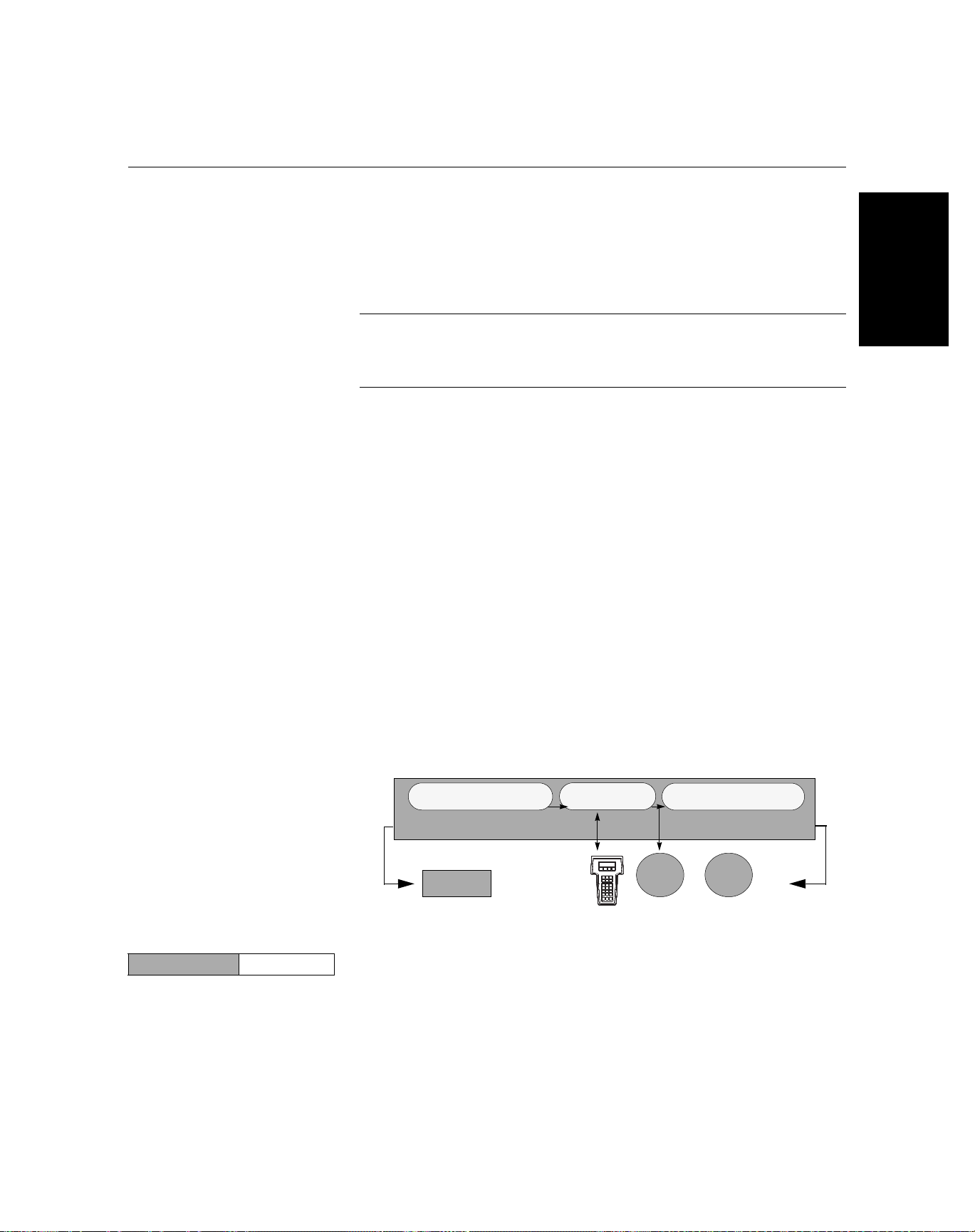
Reference Manual
00809-0100-4021, Rev DA
November 2004
Rosemount 3144P
To disable the transmitter-sensor matching feature from the HOME screen
select 1 Device Setup, 3 Configuration, 2 Sensor Config, 1 Change
Type/Conn. Choose the appropriate sensor type from the ENTER SENSOR
TYPE prompt.
D/A Output Trim or
Scaled Output Trim
When using two sensors, repeat Steps 1 – 5 for the second sensor. In Step 1,
select Sensor 2 instead of Sensor 1.
NOTE
When you disable transmitter-sensor matching, the transmitter reverts to
factory trim input. Make certain the transmitter engineering units default
correctly before placing the transmitter into service.
Callendar Van-Dusen constants can be viewed anytime by
making the following selections:
From the Home screen select 1 Device Setup, 3 Configuration, 2 Sensor
Config, 2 Show Type/Conn.
AMS
Right click on the device and select “Configuration” from the menu. Select
the “Sensor connections.” Change the Type and Connection.
The wizard will go through the required changes. In the field, select “Cal
VanDusen to enter the sensor type.
Perform an D/A output trim (scaled output trim) if the digital value for the
primary variable matches the plant standard but the transmitter’s analog
output does not match the digital value on the output device, such as the
ampmeter. The output trim function calibrates the transmitter analog output to
a 4–20 mA reference scale; the scaled output trim function calibrates to a
user-selectable reference scale. To determine the need for an output trim or a
scaled output trim, perform a loop test (see “Loop Test” on page 3-22).
HART
Figure 3-7. Dynamics of Smart
Temperature Measurement
Analog-to-Digital
Signal Conversion
Sensor and Ohm/mV
Trim adjust the signal here
Analog
Input
Transmitter Electronics Module
Microprocessor
375 Field
Communicator
Digital-to-Analog
Signal Conversion
Output and Scaled Output
Trim adjust the signal here
HART
Output
Analog
Output
Output Trim The D/A Trim command allows the user to alter the transmitter’s conversion of
HART Fast Keys 1, 2, 2, 2
the input signal to a 4–20 mA output (see Figure 3-7 on page 3-33). Calibrate
the analog output signal at regular intervals to maintain measurement
precision. To perform a digital-to-analog trim, perform the following procedure:
3-33
Page 66

Reference Manual
00809-0100-4021, Rev DA
November 2004
Rosemount 3144P
1. From the HOME screen, select 1 Device setup, 2 Diag/Service,
2 Calibration, 2 D/A trim. Set the control loop to manual and select OK.
2. Connect an accurate reference meter to the transmitter at the
CONNECT REFERENCE METER prompt. To do so, shunt the power to
the transmitter through the reference meter at some point in the loop.
Select OK after connecting the reference meter.
3. Select OK at the SETTING FLD DEV OUTPUT TO 4 MA prompt. The
transmitter outputs 4.00 mA.
4. Record the actual value from the reference meter, and enter it at the
ENTER METER VALUE prompt. The communicator prompts the user to
verify if the output value equals the value on the reference meter.
5. If the reference meter value equals the transmitter output value, then
select 1 Yes and go to step 6. If the reference meter value does not equal
the transmitter output value, then select 2 No and go to step 4.
6. Select OK at the SETTING FLD DEV OUTPUT TO 20 MA prompt and
repeat steps 4 and 5 until the reference meter value equals the
transmitter output value.
7. Return the control loop to automatic control and select OK.
HART
AMS
Right click on the device and select “Diagnostics and Calibration” from the
menu. Select the “Calibrate” and choose the “D/A Trim.”
This wizard will go through the required changes.
Scaled Output Trim The Scaled D/A Trim command matches the 4 and 20 mA points to a
HART Fast Keys 1, 2, 2, 3
user-selectable reference scale other than 4 and 20 mA (2–10 volts, for
example). To perform a scaled D/A trim, connect an accurate reference meter
to the transmitter and trim the output signal to scale as outlined in the ”Output
Trim” procedure.
AMS
Right click on the device and select “Diagnostics and Calibration” from the
menu. Select the “Calibrate” and choose the “Scaled D/A Trim.”
This wizard will go through the required changes.
3-34
Page 67

Reference Manual
00809-0100-4021, Rev DA
November 2004
Rosemount 3144P
TROUBLESHOOTING
HART / 4–20 mA If a malfunction is suspected despite the absence of a diagnostics message
on the 375 Field Communicator display, follow the procedures described in
Table 3-1 to verify that transmitter hardware and process connections are in
good working order. Under each of four major symptoms, specific suggestions
are offered for solving problems. Always deal with the most likely and
easiest-to-check conditions first.
Advanced troubleshooting information is available in Table 3-2 on page 3-36.
Table 3-1. HART / 4–20 mA Basic Troubleshooting
Symptom Potential Source Corrective Action
Transmitter Does Not
Communicate with 375 Field
Communicator
High Output
Erratic Output
Low Output or No Output
Loop Wiring
Sensor Input
Failure or Connection
Loop Wiring
Power Supply
Electronics Module
Loop wiring
Electronics Module
Sensor Element • Connect a 375 Field Communicator and enter the transmitter test mode to
Loop Wiring • Check for adequate voltage to the transmitter. It should be 12.0 to 42.4 V dc
Electronics Module • Connect a 375 Field Communicator and check the sensor limits to ensure
• Check the revision level of the transmitter device descriptors (DDs) stored in
your communicator. The communicator should report Dev v3, DD v2
(improved), or Dev v2, DD v1 (previous). Contact Emerson Process
Management Customer Central for assistance.
• Check for a minimum of 250 ohms resistance between the power supply and
375 Field Communicator connection.
• Check for adequate voltage to the transmitter. If a 375 Field Communicator is
connected and 250 ohms resistance is properly in the loop, then the transmitter
requires a minimum of 12.0 V at the terminals to operate (over entire 3.90 to
20.5 mA operating range), and 17.5 V minimum to communicate digitally.
• Check for intermittent shorts, open circuits, and multiple grounds.
• Connect a 375 Field Communicator and enter the transmitter test mode to
isolate a sensor failure.
• Check for a sensor open circuit.
• Check if the process variable is out of range.
• Check for dirty or defective terminals, interconnecting pins, or receptacles.
• Check the output voltage of the power supply at the transmitter terminals. It
should be 12.0 to 42.4 V dc (over entire 3.90 to 20.5 mA operating range).
• Connect a 375 Field Communicator and enter the transmitter test mode to
isolate module failure.
• Connect a 375 Field Communicator and check the sensor limits to ensure
calibration adjustments are within the sensor range.
• Check for adequate voltage to the transmitter. It should be 12.0 to 42.4 V dc at
the transmitter terminals (over entire 3.90 to 20.5 mA operating range).
• Check for intermittent shorts, open circuits, and multiple grounds.
• Connect a 375 Field Communicator and enter the loop test mode to generate
signals of 4 mA, 20 mA, and user-selected values.
• Connect a 375 Field Communicator and enter the transmitter test mode to
isolate module failure.
isolate a sensor failure.
• Check if the process variable is out of range.
(over entire 3.90 to 20.5 mA operating range).
• Check for shorts and multiple grounds.
• Check for proper polarity at the signal terminal.
• Check the loop impedance.
• Connect a 375 Field Communicator and enter the loop test mode.
• Check wire insulation to detect possible shorts to ground.
calibration adjustments are within the sensor range.
• Connect a 375 Field Communicator and enter the transmitter test mode to
isolate an electronics
module failure.
HART
3-35
Page 68

Rosemount 3144P
Reference Manual
00809-0100-4021, Rev DA
November 2004
HART
Table 3-2. 375 Field Communicator Error Warning Descriptions – HART
Message Description
Add item for ALL device types or only for
this ONE device type
Command not implemented The connected device does not support this function.
Communication error Either a device sends back a response indicating that the message it received was unintelligible,
Configuration memory not compatible
with connected device
Device busy The connected device is busy performing another task.
Device disconnected Device fails to respond to a command.
Device write protected Device is in write-protect mode. Data can not be written.
Device write protected. Do you still want
to shut off?
Display value of variable on hot key
menu?
Download data from configuration
memory
to device
Exceed field width Indicates that the field width for the current arithmetic variable exceeds the device-specified
Exceed precision Indicates that the precision for the current arithmetic variable exceeds the device-specified
Ignore next 50 occurrences of status? Asked after displaying device status. Softkey answer determines whether next 50 occurrences of
Illegal character An invalid character for the variable type was entered.
Illegal date The day portion of the date is invalid.
Illegal month The month portion of the date is invalid.
Illegal year The year portion of the date is invalid.
Incomplete exponent The exponent of a scientific notation floating point variable
Incomplete field The value entered is not complete for the variable type.
Looking for a device Polling for multidropped devices at addresses 1–15.
Mark as read
only variable on
hotkey menu?
No device configuration in configuration
memory
No device found Poll of address zero fails to find a device, or poll of all addresses fails to find a device if auto-poll
No hotkey menu available for this device. There is no menu named “hotkey” defined in the device description for this device.
No offline
devices available
No simulation
devices available
No UPLOAD_VARIABLES in ddl for this
device
No valid items The selected menu or edit display contains no valid items.
OFF KEY DISABLED Appears when the user attempts to turn the 375 Field Communicator off before sending modified
Online device disconnected with unsent
data. RETRY or OK to lose data
Asks the user whether the hot key item being added should be added for all device types or only
for the type of device that is connected.
or the 375 Field Communicator cannot understand the response from the device.
The configuration stored in memory is incompatible with the device to which a transfer has been
requested.
Device is in write-protect mode. Press YES to turn the 375 Field Communicator off and lose the
unsent data.
Asks whether the value of the variable should be displayed adjacent to its label on the hot key
menu if the item being
added to the hot key menu is a variable.
Prompts user to press SEND softkey to initiate a memory to device transfer.
description edit format.
description edit format.
device status will be ignored
or displayed.
is incomplete.
Asks whether the user should be allowed to edit the variable from the hotkey menu if the item
being added to the hotkey menu is
a variable.
There is no configuration saved in memory available to
re-configure off-line or transfer to a device.
is enabled.
There are no device descriptions available to be used to configure a device offline.
There are no device descriptions available to simulate a device.
There is no menu named “upload_variables” defined in the
device description for this device. This menu is required for
offline configuration.
data or before completing a method.
There is unsent data for a previously connected device. Press RETRY to send data, or press OK
to disconnect and lose
unsent data.
(1)
3-36
Page 69

Reference Manual
00809-0100-4021, Rev DA
November 2004
Rosemount 3144P
Table 3-2. 375 Field Communicator Error Warning Descriptions – HART
Message Description
Out of memory for hotkey configuration.
Delete unnecessary items.
Overwrite existing configuration memory Requests permission to overwrite existing configuration either by a device-to-memory transfer or
Press OK Press the OK softkey. This message usually appears after an error message from the application
Restore device value? The edited value that was sent to a device was not properly implemented. Restoring the device
Save data from device to configuration
memory
Saving data to configuration memory Data is being transferred from a device to configuration memory.
Sending data to device Data is being transferred from configuration memory to a device.
There are write only variables which have
not been edited.
Please edit them
There is unsent data. Send it before
shutting off?
Too few data
bytes received
Transmitter fault Device returns a command response indicating a fault with the connected device.
Units for <variable label> has changed.
Unit must be sent before editing, or invalid
data will be sent.
Unsent data to online device. SEND or
LOSE data
Use up/down arrows to change contrast.
Press DONE when done.
Value out of range The user-entered value is either not within the range for the given type and size of variable or not
<message> occurred reading/writing
<variable label>
<variable label> has an unknown value.
Unit must be sent before editing, or invalid
data will be sent.
(1) Variable parameters within the text of a message are indicated with <variable parameter>.
Reference to the name of another message is identified by [another message].
There is no more memory available to store additional hotkey items. Unnecessary items should
be deleted to make space available.
by an offline configuration. User answers using the softkeys.
or as a result of HART communications.
value returns the variable to its original value.
Prompts user to press SAVE softkey to initiate a device-to-memory transfer.
There are write-only variables that have not been set by the user. These variables should be set
or invalid values may be sent to the device.
Press YES to send unsent data and turn the 375 Field Communicator off. Press NO to turn the
375 Field Communicator off and lose the unsent data.
Command returns fewer data bytes than expected as determined by the device description.
The engineering units for this variable have been edited. Send engineering units to the device
before editing this variable.
There is unsent data for a previously connected device which must be sent or thrown away
before connecting to another device.
Gives direction to change the contrast of the 375 Field Communicator display.
within the min/max specified by the device.
Either a read/write command indicates too few data bytes received, transmitter fault, invalid
response code, invalid response command, invalid reply data field, or failed pre- or post-read
method; or a response code of any class other than SUCCESS is returned reading a particular
variable.
A variable related to this variable has been edited. Send related variable to the device before
editing this variable.
(1)
HART
3-37
Page 70

HART
Reference Manual
00809-0100-4021, Rev DA
Rosemount 3144P
November 2004
LCD Display The LCD display displays abbreviated diagnostic messages for
troubleshooting the transmitter. To accommodate two-word messages, the
display alternates between the first and second word. Some diagnostic
messages have a higher priority than others, so messages appear according
to their priority, with normal operating messages appearing last. Messages on
the Process Variable line refer to general device conditions, while messages
on the Process Variable Unit line refer to specific causes for these conditions.
A description of each diagnostic message follows.
Table 3-3. LCD Display Error Warning Descriptions
Message Description
[BLANK] If the meter does not appear to function, make sure the transmitter is configured for the meter option you desire.
The meter will not function if the LCD Display option is set to Not Used.
FAIL -or- HDWR FAIL This message indicates one of several conditions including:
SNSR 1 FAIL -orSNSR 2 FAIL
SNSR 1 SAT -orSNSR 2 SAT
HOUSG SAT The transmitter operating temperature limits (–40 to 185 °F (40 to
LOOP FIXED During a loop test or a 4–20 mA output trim, the analog output defaults to a fixed value. The Process Variable
OFLOW The location of the decimal point, as configured in the meter setup, is not compatible with the value to be
HOT BU Hot Backup is enabled and Sensor 1 has failed. This message is displayed on the Process Variable line and is
WARN DRIFT ALERT Drift Alert warning is enabled and the difference between Sensor 1 and Sensor 2 has exceeded the
ALARM DRIFT ALERT The analog output is in alarm. Drift Alert alarm is enabled and the difference between Sensor 1 and Sensor 2
ALARM The digital and analog outputs are in alarm. Possible causes of this condition include, but are not limited to, an
WARN The transmitter is still operating, but something is not correct. Possible causes of this condition include, but are
The transmitter has experienced an electronics module failure.
The transmitter self-test has failed.
If diagnostics indicate a failure of the electronics module, replace the electronics module with a new one.
Contact the nearest Emerson Process Management Field Service Center if necessary.
The transmitter has detected an open or shorted sensor condition. The sensor(s) might be disconnected,
connected improperly, or malfunctioning. Check the sensor connections and sensor continuity.
The temperature sensed by the transmitter exceeds the sensor limits for this particular sensor type.
85 °C)) have been exceeded.
line of the display alternates between the amount of current selected in milliamperes and “WARN.” The Process
Variable Unit line toggles between “LOOP,” “FIXED,” and the amount of current selected in milliamperes.
displayed by the meter. For example, if the meter is measuring a process temperature greater than 9.9999
degrees, and the meter decimal point is set to 4 digit precision, the meter will display an “OFLOW” message
because it is only capable of displaying a maximum value of 9.9999 when set to 4 digit precision.
always accompanied by a more descriptive message on the Process Variable Unit line. In the case of a Sensor
1 failure with Hot Backup enabled, for example, the Process Variable line displays “HOT BU,” and the Process
Variable Unit line alternates between “SNSR 1” and “FAIL.”
user-specified limit. One of the sensors may be malfunctioning. The Process Variable line displays “WARN” and
the Process Variable Unit line alternates between “DRIFT” and “ALERT.”
has exceeded the user-specified limit. The transmitter is still operating, but one of the sensors may be
malfunctioning. The Process Variable line displays “ALARM” and the Process Variable Unit line alternates
between “DRIFT” and “ALERT.”
electronics failure or an open sensor. This message is displayed on the Process Variable line and is always
accompanied by a more descriptive message on the Process Variable Unit line. In the case of a Sensor 1 failure,
for example, the Process Variable line displays “ALARM,” and the Process Variable Unit line alternates between
“SNSR 1” and “FAIL.”
not limited to, an out-of-range sensor, a fixed loop, or an open sensor condition. In the case of a Sensor 2 failure
with Hot Backup enabled, the Process Variable line displays “WARN,” and the Process Variable Unit line
alternates between “SNSR 2” and “RANGE.”
3-38
Page 71

Reference Manual
00809-0100-4021, Rev DA
November 2004
Rosemount 3144P
AMS Software (HART /
4-20 mA only)
If a malfunction is suspected despite the absence of a diagnostics message,
follow the procedures described in Table 3-4 to verify that transmitter
hardware and process connections are in good working order. Under each of
four major symptoms, specific suggestions are offered for solving problems.
Always deal with the most likely and easiest-to-check conditions first.
Advanced troubleshooting information is available in Table 3-5 on page 3-40.
AMS also provides help screens to assist in message communication. See
“When the Drift Alert warning or alarm is enable, they indicate that the
differences between Sensor 1 and Sensor 2 has exceeded the user-specified
limit. One of the sensors may be malfunctioning. The sensors should both be
investigated at the earliest opportunity.” on page 3-42.
Table 3-4. AMS Basic Troubleshooting
Symptom Potential Source Corrective Action
Transmitter Does Not
Communicate with AMS
Software
High Output
Erratic Output
Low Output or No Output
Loop Wiring
Sensor Input
Failure or Connection
Loop Wiring
Power Supply
Electronics Module
Loop wiring
Electronics Module
Sensor Element • Using AMS, set the transmitter test mode to isolate a sensor failure.
Loop Wiring • Check for adequate voltage to the transmitter. It should be 12.0 to 42.4 V dc
Electronics Module • Using AMS, check the sensor limits to ensure calibration adjustments are within
• Check the revision level of the transmitter device descriptors (DDs) stored in
your software. The communicator should report Dev v3, DD v2 (improved), or
Dev v2, DD v1 (previous). Contact Emerson Process Management Customer
Central for assistance.
• Check for a minimum of 250 ohms resistance between the power supply and
AMS software.
• Check for adequate voltage to the transmitter. If the AMS software is
connected and 250 ohms resistance is properly in the loop, then the transmitter
requires a minimum of 12.0 V at the terminals to operate (over entire 3.90 to
20.5 mA operating range), and 17.5 V minimum to communicate digitally.
• Check for intermittent shorts, open circuits, and multiple grounds.
• Using AMS, set the transmitter test mode to isolate a sensor failure.
• Check for a sensor open circuit.
• Check if the process variable is out of range.
• Check for dirty or defective terminals, interconnecting pins, or receptacles.
• Check the output voltage of the power supply at the transmitter terminals. It
should be 12.0 to 42.4 V dc (over entire 3.90 to 20.5 mA operating range).
• Using AMS, set the transmitter test mode to isolate module failure.
• Using AMS, check the sensor limits to ensure calibration adjustments are
within the sensor range.
• Check for adequate voltage to the transmitter. It should be 12.0 to 42.4 V dc at
the transmitter terminals (over entire 3.90 to 20.5 mA operating range).
• Check for intermittent shorts, open circuits, and multiple grounds.
• Using AMS, set the loop test mode to generate signals of 4 mA, 20 mA, and
user-selected values.
• Using AMS, set the transmitter test mode to isolate module failure.
• Check if the process variable is out of range.
(over entire 3.90 to 20.5 mA operating range).
• Check for shorts and multiple grounds.
• Check for proper polarity at the signal terminal.
• Check the loop impedance.
• Set the loop test mode.
• Check wire insulation to detect possible shorts to ground.
the sensor range.
• Using AMS, set the transmitter test mode to isolate an electronics module
failure.
HART
3-39
Page 72

Rosemount 3144P
Reference Manual
00809-0100-4021, Rev DA
November 2004
HART
Table 3-5. AMS Error Warning Descriptions
Message Description
Command not implemented The connected device does not support this function.
Communication error Either a device sends back a response indicating that the message it received was unintelligible,
or the 375 Field Communicator cannot understand the response from the device.
Device busy The connected device is busy performing another task.
Device disappears from list Device fails to respond to a command.
Device write protected Device is in write-protect mode. Data can not be written.
Illegal character An invalid character for the variable type was entered.
Illegal date The day portion of the date is invalid.
Illegal month The month portion of the date is invalid.
Illegal year The year portion of the date is invalid.
Incomplete exponent The exponent of a scientific notation floating point variable
Incomplete field The value entered is not complete for the variable type.
Sending data to device Data is being transferred from configuration memory to a device.
There are write only variables which have
not been edited.
Please edit them
There is unsent data. Send it before
shutting off?
Too few data
bytes received
Transmitter fault Device returns a command response indicating a fault with the connected device.
Units for <variable label> has changed.
Unit must be sent before editing, or invalid
data will be sent.
Unsent data to online device. SEND or
LOSE data
Value out of range The user-entered value is either not within the range for the given type and size of variable or not
<message> occurred reading/writing
<variable label>
<variable label> has an unknown value.
Unit must be sent before editing, or invalid
data will be sent.
(1) These messages are communicated through pop-up menus.
is incomplete.
There are write-only variables that have not been set by the user. These variables should be set
or invalid values may be sent to the device.
Press YES to send unsent data and turn the 375 Field Communicator off. Press NO to turn the
375 Field Communicator off and lose the unsent data.
Command returns fewer data bytes than expected as determined by the device description.
The engineering units for this variable have been edited. Send engineering units to the device
before editing this variable.
There is unsent data for a previously connected device which must be sent or thrown away
before connecting to another device.
within the min/max specified by the device.
Either a read/write command indicates too few data bytes received, transmitter fault, invalid
response code, invalid response command, invalid reply data field, or failed pre- or post-read
method; or a response code of any class other than SUCCESS is returned reading a particular
variable.
A variable related to this variable has been edited. Send related variable to the device before
editing this variable.
(1)
3-40
Page 73

Reference Manual
00809-0100-4021, Rev DA
November 2004
Rosemount 3144P
AMS Screens AMS provides advanced diagnostic messages, as well as help screens for the
messages. Using the help screens can provide quick reference to remedying
the situation. The trouble shooting section for this manual can also be pasted
in AMS to assist in quick and accurate troubleshooting reference.
Alarms and Alerts
Right click on the device and select “Process Variables”. This screen shows
the sensor reading and status of the sensor and transmitters. If no alarms or
alerts are activated, the screen will look like this:
Sensor Failure
When the transmitter has detected an open or shorted sensor condition, the
sensor(s) might be disconnected, connected improperly, or malfunctioning.
Check the Sensor connections and continuity. Replace the sensor if
necessary.
HART
By right-clicking on the device and selecting “status,: the status screen
appears. This screen shows an overview of the transmitter health. Red bars
indicate system changes or that the transmitter is not working properly and
should be investigated.
3-41
Page 74

Rosemount 3144P
Reference Manual
00809-0100-4021, Rev DA
November 2004
HART
Hot BackUp
Hot Backup is enabled and Sensor 1 or Sensor 2 has failed. The following is
displayed on the Process Variable Screen. The suspect sensor should be
investigated as soon as possible, and replaced as necessary.
Sensor Drift Alarm
When the Drift Alert warning or alarm is enable, they indicate that the
differences between Sensor 1 and Sensor 2 has exceeded the user-specified
limit. One of the sensors may be malfunctioning. The sensors should both be
investigated at the earliest opportunity.
®
3-42
Page 75

Reference Manual
00809-0100-4021, Rev DA
November 2004
Rosemount 3144P
Section 4 FOUNDATION Fieldbus
Configuration
Overview . . . . . . . . . . . . . . . . . . . . . . . . . . . . . . . . . . . . . . . page 4-1
Safety Messages . . . . . . . . . . . . . . . . . . . . . . . . . . . . . . . . . page 4-1
General Block Information . . . . . . . . . . . . . . . . . . . . . . . . . page 4-2
Foundation fieldbus function blocks . . . . . . . . . . . . . . . . page 4-4
Resource Block . . . . . . . . . . . . . . . . . . . . . . . . . . . . . . . . . . page 4-5
Sensor Transducer Block . . . . . . . . . . . . . . . . . . . . . . . . . page 4-10
LCD Transducer Block . . . . . . . . . . . . . . . . . . . . . . . . . . . . page 4-11
Analog Input (AI) . . . . . . . . . . . . . . . . . . . . . . . . . . . . . . . . . page 4-14
Operation . . . . . . . . . . . . . . . . . . . . . . . . . . . . . . . . . . . . . . . page 4-20
Troubleshooting Guides . . . . . . . . . . . . . . . . . . . . . . . . . . page 4-25
OVERVIEW This section provides information on configuring, troubleshooting, operating,
and maintaining the 3144P transmitter using F
OUNDATION fieldbus protocol.
SAFETY MESSAGES Instructions and procedures in this section may require special precautions to
ensure the safety of the personnel performing the operations. Information that
potentially raises safety issues is indicated by a warning symbol ( ). Please
refer to the following safety messages before performing an operation
preceded by this symbol.
Failure to follow these installation guidelines could result in death or
serious injury.
• Make sure only qualified personnel perform the installation.
Explosions could result in death or serious injury.
• Do not remove the connection head cover in explosive atmospheres when the
circuit is live.
• Before powering a F
make sure the instruments in the loop are installed in accordance with instrinsically
safe or non-incendive field wiring practices.
• Verify that the operating atmosphere of the transmitter is consistent with the
appropriate hazardous locations certifications.
• All connection head covers must be fully engaged to meet
explosion-proof requirements.
Process leaks could result in death or serious injury.
• Do not remove the thermowell while in operation.
• Install and tighten thermowells and sensors before applying pressure
Electrical shock could cause death or serious injury.
• Use extreme caution when making contact with the leads and terminals.
OUNDATION fieldbus segment in an explosive atmosphere,
FOUNDATION Fieldbus
www.rosemount.com
Page 76

Rosemount 3144P
GENERAL BLOCK
INFORMATION
Device Description Before configuring the device, ensure the host has the appropriate Device
Node Address The transmitter is shipped at a temporary (248) address. This will enable
FOUNDATION Fieldbus
Modes The Resource, Transducer, and all function blocks in the device have modes
Reference Manual
00809-0100-4021, Rev DA
November 2004
Description file revision for this device. The device descriptor can be found on
www.rosemount.com. The initial release of the Rosemount 3144P with
OUNDATION fieldbus protocol is device revision 1.
F
OUNDATION fieldbus host systems to automatically recognize the device and
F
move it to a permanent address.
of operation. These modes govern the operation of the block. Every block
supports both automatic (AUTO) and out of service (OOS) modes. Other
modes may also be supported.
Changing Modes
To change the operating mode, set the MODE_BLK.TARGET to the desired
mode. After a short delay, the parameter MODE_BLOCK.ACTUAL should
reflect the mode change if the block is operating properly.
Permitted Modes
It is possible to prevent unauthorized changes to the operating mode of a
block. To do this, configure MODE_BLOCK.PERMITTED to allow only the
desired operating modes. It is recommended to always select OOS as one of
the permitted modes.
Types of Modes
For the procedures described in this manual, it will be helpful to understand
the following modes:
AUTO
The functions performed by the block will execute. If the block has any
outputs, these will continue to update. This is typically the normal
operating mode.
Out of Service (OOS)
The functions performed by the block will not execute. If the block has any
outputs, these will typically not update and the status of any values passed
to downstream blocks will be “BAD”. To make some changes to the
configuration of the block, change the mode of the block to OOS. When
the changes are complete, change the mode back to AUTO.
MAN
In this mode, variables that are passed out of the block can be manually
set for testing or override purposes.
Other Types of Modes
Other types of modes are Cas, RCas, ROut, IMan and LOW. Some of
these may be supported by different function blocks in the 3144P. For
more information, see the Function Block manual (document number
00809-0100-4783).
4-2
Page 77
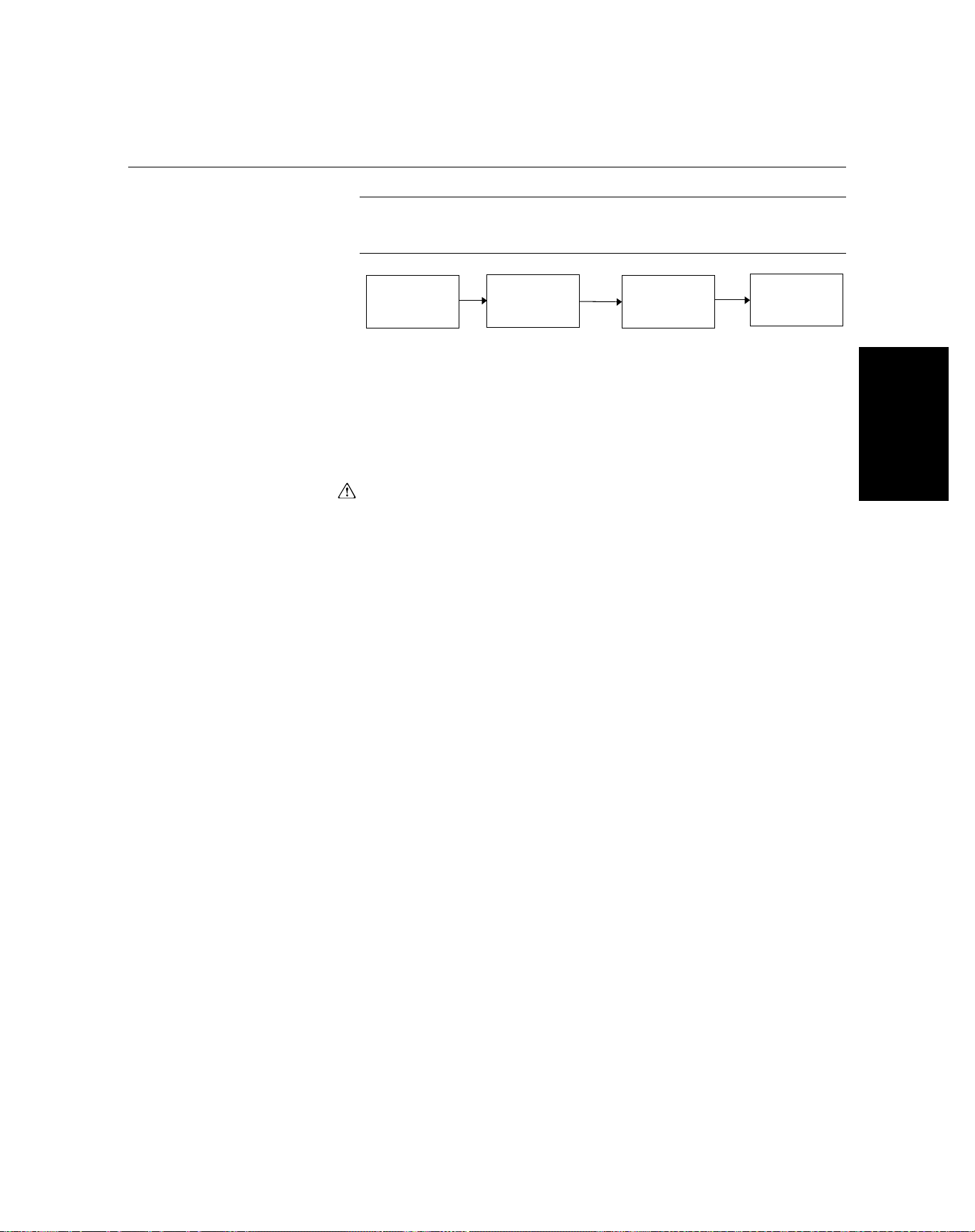
Reference Manual
00809-0100-4021, Rev DA
November 2004
Rosemount 3144P
NOTE
When an upstream block is set to OOS, this will impact the output status of all
downstream blocks. The figure below depicts the hierarchy of blocks:
Resource
Block
Transducer
Block
Analog Input
(AI Block)
Other
function
blocks
Link Active Scheduler The 3144P can be designated to act as the backup Link Active Scheduler
(LAS) in the event that the designated LAS is disconnected from the segment.
As the backup LAS, the 3144P will take over the management of
communications until the host is restored.
The host system may provide a configuration tool specifically designed to
designate a particular device as a backup LAS. Otherwise, this can be
configured manually as follows:
1. Access the Management Information Base (MIB) for the 3144P.
To activate the LAS capability, write 0x02 to the
BOOT_OPERAT_FUNCTIONAL_CLASS object (Index 605). To
deactivate, write 0x01.
2. Restart the device.
Block Instantiation Rosemount devices are pre-configured with function blocks at the factory, the
default configuration for the 3144P is listed below. The 3144P can have up to
three additional instantiated function blocks (nine instantiated, four
permanent, three additional).
• 3 Analog Input Blocks (tag names AI 1400, AI 1500, AI 1600)
• 2 Proportional/Integral/Derivative Block (tag name PID 1700, PID 1800)
• Input Selector (tag names ISEL 1900)
• Signal Characterizer (tag name CHAR 2000)
• Arithmetic (tag name ARTH 2100)
• Output Splitter (tag name OSPL 2200)
FOUNDATION Fieldbus
The four permanent blocks are as follows:
•Resource
•Transducer
•LCD
•SPM
The 3144P supports the use of Function Block Instantiation. When a device
supports block instantiation, the number of blocks and block types can be
defined to match specific application needs.The number of blocks that can be
instantiated is only limited by the amount of memory within the device and the
block types that are supported by the device. Instantiation does not apply to
permanent device blocks like the Resource, Sensor Transducer, LCD
Transducer, and Advanced Diagnostics Blocks.
By reading the parameter “FREE_SPACE” in the Resource block you can
determine how many blocks you can instantiate. Each block that you
instantiate takes up 4.5% of the “FREE_SPACE”.
4-3
Page 78

Rosemount 3144P
Capabilities Virtual Communication Relationship (VCRs)
Table 4-1. Network Parameters
FOUNDATION Fieldbus
Reference Manual
00809-0100-4021, Rev DA
November 2004
Block instantiation is done by the host control system or configuration tool, but
not all hosts are required to implement this functionality. Please refer to your
specific host or configuration tool manual for more information.
There are a total of 20 VCRs. One is permanent and 19 are fully configurable
by the host system. Thirty link objects are available.
Network Parameter Value
Slot Time 8
Maximum Response Delay 2
Maximum Inactivity to Claim LAS Delay 32
Minimum Inter DLPDU Delay 8
Time Sync class 4 (1 ms)
Maximum Scheduling Overhead 21
Per CLPDU PhL Overhead 4
Maximum Inter-channel Signal Skew 0
Required Number of Post-transmission-gab-ext Units 0
Required Number of Preamble-extension Units 1
FOUNDATION FIELDBUS
FUNCTION BLOCKS
Block Execution times
Block Execution Time
Resource –
Transducer –
LCD Block –
Advanced Diagnostics –
Analog Input 1, 2, 3 60 ms
PID 1 and 2 with Autotune 90 ms
Input Selector 65 ms
Signal Characterizer 45 ms
Arithmetic 60 ms
Output Splitter 60 ms
For reference information on the Resource, Sensor Transducer, AI, LCD
Transducer blocks refer to “Foundation Fieldbus Block Information” on
page A-1. Reference information on the PID block can be found in the
Function Block manual document number 00809-0100-4783.
Resource Block (index number 1000)
The Resource Function Block (RB) contains diagnostic, hardware and
electronics information. There are no linkable inputs or outputs to the
Resource Block.
Sensor Transducer Block (index number 1100)
The Sensor Transducer Function Block (STB) temperature measurement
data, including sensor and terminal temperature, The STB also includes
information about sensor type, engineering units, linearization, reranging,
damping, temperature compensation, and diagnostics.
4-4
LCD Transducer Block (index number 1200)
The LCD Transducer Block is used to configure the LCD display.
Page 79

Reference Manual
00809-0100-4021, Rev DA
November 2004
Rosemount 3144P
Analog Input Block (index number 1400, 1500, and 1600)
The Analog Input Function Block (AI) processes the measurements from the
sensor and makes them available to other function blocks. The output value
from the AI block is in engineering units and contains a status indicating the
quality of the measurement. The AI block is widely used for scaling
functionality.
PID Block (index number 1700 and 1800)
The PID Function Block combines all of the necessary logic to perform
proportional/integral/derivative (PID) control. The block supports mode
control, signal scaling and limiting, feed forward control, override tracking,
alarm limit detection, and signal status propagation.
The block supports two forms of the PID equation: Standard and Series. You
can choose the appropriate equation using the MATHFORM parameter. The
Standard ISA PID equation is the default selection and Autotune.
Input Selector (index number 1900)
The signal selector block provides selection of up to four inputs and generates
an output based on the configured action. This block normally receives its
inputs from AI blocks. The block performs maximum, minimum, middle,
average and ‘first good’ signal selection.
FOUNDATION Fieldbus
RESOURCE BLOCK
FEATURES and
FEATURES_SEL
Output Splitter (index number OSPL 2200)
The output splitter block provides the capability to drive two control outputs
from a single input. Each output is a linear function of some portion of the
input.
Arithmetic (index number 2100)
This block is designed to permit simple use of popular measurement math
functions. The user does not have to know how to write equations. The math
algorithm is selected by name, chosen by the user for the function to be done.
Signal Characterizer (index number 2000)
The signal characterizer block has two sections, each with an output that is a
non-linear function of the respective input. The non-linear function is
determined by a single look-up table with 21 arbitrary x-y pairs. The status of
an input is copied to the corresponding output, so the block may be used in
the control or process signal path.
The parameters FEATURES and FEATURE_SEL determine optional
behavior of the 3144P.
FEATURES
The FEATURES parameter is read only and defines which features are
supported by the 3144P. Below is a list of the FEATURES the 3144P
supports.
UNICODE
All configurable string variables in the 3144P, except tag names, are octet
strings. Either ASCII or Unicode may be used. If the configuration device is
generating Unicode octet strings, you must set the Unicode option bit.
4-5
Page 80

Rosemount 3144P
FOUNDATION Fieldbus
Reference Manual
00809-0100-4021, Rev DA
November 2004
REPORTS
The 3144P supports alert reports. The Reports option bit must be set in the
features bit string to use this feature. If it is not set, the host must poll for
alerts.
SOFT W LOCK and HARD W LOCK
Inputs to the security and write lock functions include the hardware security
switch, the hardware and software write lock bits of the FEATURE_SEL
parameter, the WRITE_LOCK parameter, and the DEFINE_WRITE_LOCK
parameter.
The WRITE_LOCK parameter prevents modification of parameters within the
device except to clear the WRITE_LOCK parameter. During this time, the
block will function normally updating inputs and outputs and executing
algorithms. When the WRITE_LOCK condition is cleared, a WRITE_ALM
alert is generated with a priority that corresponds to the WRITE_PRI
parameter.
The FEATURE_SEL parameter enables the user to select a hardware or
software write lock or no write lock capability. To enable the hardware security
function, enable the HW_SEL bit in the FEATURE_SEL parameter. When this
bit has been enabled the WRITE_LOCK parameter becomes read only and
will reflect the state of the hardware switch. In order to enable the software
write lock, the SW_SEL bit must be set in the FEATURE_SEL parameter.
Once this bit is set, the WRITE_LOCK parameter may be set to “Locked” or
“Not Locked.” Once the WRITE_LOCK parameter is set to “Locked” by either
the software or the hardware lock, all user requested writes as determined by
the DEFINE_WRITE_LOCK parameter shall be rejected.
The DEFINE_WRITE_LOCK parameter allows the user to configure whether
the write lock functions (both software and hardware) will control writing to all
blocks, or only to the resource and transducer blocks. Internally updated data
such as process variables and diagnostics will not be restricted by the
security switch.
The following table displays all possible configurations of the WRITE_LOCK
parameter.
FEATURE_SEL
HW_SEL bit
0 (off) 0 (off) NA 1 (unlocked) Read only NA All
0 (off) 1 (on) NA 1 (unlocked) Read/Write NA All
0 (off) 1 (on) NA 2 (locked) Read/Write Physical Function
0 (off) 1 (on) NA 2 (locked) Read/Write Everything None
1 (on) 0 (off)
1 (on) 0 (off) 1 (locked) 2 (locked) Read only Physical Function
1 (on) 0 (off) 1 (locked) 2 (locked) Read only Everything None
(1) The hardware and software write lock select bits are mutually exclusive and the hardware select has the highest priority. When the HW_SEL bit if set to 1
(on), the SW_SEL bit is automatically set to 0 (off) and is read only.
FEATURE_SEL
SW_SEL bit
(1)
SECURITY SWITCH WRITE_LOCK
0 (unlocked) 1 (unlocked) Read only NA All
WRITE_LOCK
Read/Write
DEFINE_WRITE_LOCK
Write access
to blocks
Blocks only
Blocks only
FEATURES_SEL
FEATURES_SEL is used to turn on any of the supported features. The default
setting of the 3144P does not select any of these features. Choose one of the
supported features if any.
4-6
Page 81

Reference Manual
00809-0100-4021, Rev DA
November 2004
MAX_NOTIFY
The MAX_NOTIFY parameter value is the maximum number of alert reports
that the resource can have sent without getting a confirmation, corresponding
to the amount of buffer space available for alert messages. The number can
be set lower, to control alert flooding, by adjusting the LIM_NOTIFY
parameter value. If LIM_NOTIFY is set to zero, then no alerts are reported.
Rosemount 3144P
PlantWeb™ Alerts The alerts and recommended actions should be used in conjunction with
“Operation” on page 4-20.
The Resource Block will act as a coordinator for PlantWeb alerts. There will
be three alarm parameters (FAILED_ALARM, MAINT_ALARM, and
ADVISE_ALARM) which will contain information regarding some of the device
errors which are detected by the transmitter software. There will be a
RECOMMENDED_ACTION parameter which will be used to display the
recommended action text for the highest priority alarm and a HEALTH_INDEX
parameters (0 - 100) indicating the overall health of the transmitter.
FAILED_ALARM will have the highest priority followed by MAINT_ALARM
and ADVISE_ALARM will be the lowest priority.
FAILED_ALARMS
A failure alarm indicates a failure within a device that will make the device or
some part of the device non-operational. This implies that the device is in
need of repair and must be fixed immediately. There are five parameters
associated with FAILED_ALARMS specifically, they are described below.
FOUNDATION Fieldbus
FAILED_ENABLED
This parameter contains a list of failures in the device which makes the
device non-operational that will cause an alert to be sent. Below is a list of
the failures with the highest priority first.
1. Electronics
2. NV Memory
3. HW / SW Incompatible
4. Primary Value
5. Secondary Value
FAILED_MASK
This parameter will mask any of the failed conditions listed in
FAILED_ENABLED. A bit on means that the condition is masked out from
alarming and will not be reported.
FAILE D _ P R I
Designates the alerting priority of the FAILED_ALM, see “Alarm Priority”
on page 4-18. The default is 0 and the recommended value are between 8
and 15.
FAILED_ACTIVE
This parameter displays which of the alarms is active. Only the alarm with
the highest priority will be displayed. This priority is not the same as the
FAILED_PRI parameter described above. This priority is hard coded within
the device and is not user configurable.
FAILE D _ A L M
Alarm indicating a failure within a device which makes the device
non-operational.
4-7
Page 82

Rosemount 3144P
Reference Manual
00809-0100-4021, Rev DA
November 2004
MAINT_ALARMS
A maintenance alarm indicates the device or some part of the device needs
maintenance soon. If the condition is ignored, the device will eventually fail.
There are five parameters associated with MAINT_ALARMS, they are
described below.
MAINT_ENABLED
The MAINT_ENABLED parameter contains a list of conditions indicating
the device or some part of the device needs maintenance soon.
FOUNDATION Fieldbus
Below is a list of the conditions with the highest priority first.
1. Primary Value Degraded
2. Secondary Value Degraded
3. Configuration Error
4. Calibration Error
MAINT_MASK
The MAINT_MASK parameter will mask any of the failed conditions listed
in MAINT_ENABLED. A bit on means that the condition is masked out
from alarming and will not be reported.
MAINT_PRI
MAINT_PRI designates the alarming priority of the MAINT_ALM, “Process
Alarms” on page 4-17. The default is 0 and the recommended values is 3
to 7.
MAINT_ACTIVE
The MAINT_ACTIVE parameter displays which of the alarms is active.
Only the condition with the highest priority will be displayed. This priority is
not the same as the MAINT_PRI parameter described above. This priority
is hard coded within the device and is not user configurable.
MAINT_ALM
An alarm indicating the device needs maintenance soon. If the condition is
ignored, the device will eventually fail.
4-8
Advisory Alarms
An advisory alarm indicates informative conditions that do not have a direct
impact on the device's primary functions There are five parameters
associated with ADVISE_ALARMS, they are described below.
ADVISE_ENABLED
The ADVISE_ENABLED parameter contains a list of informative
conditions that do not have a direct impact on the device's primary
functions. Below is a list of the advisories with the highest priority first.
1. NV Writes Deferred
2. SPM Process Anomaly detected
ADVISE_MASK
The ADVISE_MASK parameter will mask any of the failed conditions listed
in ADVISE_ENABLED. A bit on means the condition is masked out from
alarming and will not be reported.
ADVISE_PRI
ADVISE_PRI designates the alarming priority of the ADVISE_ALM, see
“Process Alarms” on page 4-17. The default is 0 and the recommended
values are 1 or 2.
Page 83

Reference Manual
00809-0100-4021, Rev DA
November 2004
Rosemount 3144P
ADVISE_ACTIVE
The ADVISE_ACTIVE parameter displays which of the advisories is
active. Only the advisory with the highest priority will be displayed. This
priority is not the same as the ADVISE_PRI parameter described above.
This priority is hard coded within the device and is not user configurable.
ADVISE_ALM
ADVISE_ALM is an alarm indicating advisory alarms. These conditions do
not have a direct impact on the process or device integrity.
Recommended Actions
for PlantWeb Alerts
Table 4-2.
RB.RECOMMENDED_ACTION
RECOMMENDED_ACTION
The RECOMMENDED_ACTION parameter displays a text string that will give
a recommended course of action to take based on which type and which
specific event of the PlantWeb alerts are active.
Alarm Type
None None No action required
Advisory
Maintenance
PlantWeb Alerts
Failed
Diagnostic
Error
Failed/Maint/Advise
Active Event
NV Writes Deferred Non-volatile writes have been deferred, leave
Configuration Error Re-write the Sensor Configuration
Primary Value
Degraded
Calibration Error Retrim the device
Secondary Value
Degraded
Electronics Failure Replace the Device
HW / SW Incompatible Verify the Hardware Revision is compatible
NV Memory Failure Reset the device then download the Device
Primary Value Failure Verify the instrument process is within the
Secondary Value
Failure
Sensor Drift Alarm or
Hot BU active
Recommended Action
Text String
the device powered until the advisory goes
away
Confirm the operating range of the applied
sensor and/or verify the sensor connection and
device environment
Verify the ambient temperature is within
operating limits
with the Software Revision
Configuration
Sensor range and / or confirm sensor
configuration and wiring.
Verify the ambient temperature is within
operating limits
Verify sensor range and/or confirm sensor
configuration and wiring.
FOUNDATION Fieldbus
Resource Block
Diagnostics
Table 4-3. Resource Block
BLOCK_ERR messages
Block Errors
Table 4-3 lists conditions reported in the BLOCK_ERR parameter.
Condition Name and Description
Other
Device Needs Maintenance Now
Memory Failure: A memory failure has occurred in FLASH, RAM, or EEPROM memory
Lost NV Data: Non-volatile data that is stored in non-volatile memory has been lost.
Device Needs Maintenance Now
Out of Service: The actual mode is out of service.
4-9
Page 84

Rosemount 3144P
Table 4-4. Resource Block
SUMMARY_STATUS messages
Table 4-5. Resource Block
RB.DETAILED_STATUS
FOUNDATION Fieldbus
Reference Manual
00809-0100-4021, Rev DA
November 2004
Condition Name
No repair needed
Repairable
Call Service Center
RB.DETAILED_STATUS Description
Sensor Transducer block error. Active when any SENSOR_DETAILED_STAUS bit is on
Manufacturing Block integrity error The manufacturing block size, revision, or checksum is
wrong
Hardware/software incompatible Verify the manufacturing block revision and the
hardware revision are correct/compatible with the
software revision.
Non-volatile memory integrity error Invalid checksum on a block of NV data
ROM integrity error Invalid application code checksum
Lost deferred NV data Device has been power-cycled while non-volatile writes
were being deferred to prevent premature memory
failure, the write operations have been deferred.
NV Writes Deferred A high number of writes has been detected to
non-volatile memory. To prevent premature failure, the
write operations have been deferred.
SENSOR TRANSDUCER
BLOCK
NOTE
When the engineering units of the XD_SCALE in the associated AI Block are
selected, the engineering units in the Transducer Block change to the same
units. THIS IS THE ONLY WAY TO CHANGE THE ENGINEERING UNITS IN
THE SENSOR TRANSDUCER BLOCK.
Damping The damping parameter in the Transducer Block may be used to filter
measurement noise. By increasing the damping time, the transmitter will have
a slower response time, but will decrease the amount of process noise that is
translated to the Transducer Block Primary Value. Because both the LCD and
AI Block get input from the Transducer Block, adjusting the damping
parameter will effect the values passed to both blocks.
NOTE
The AI Block has it's own filtering parameter called PV_FTIME. For simplicity,
it is better to do filtering in the Transducer Block as damping will be applied to
primary value on every sensor update. If filtering is done in AI block, damping
will be applied to output every macrocycle. The LCD will display value from
Transducer block.
Sensor Transducer Block
Diagnostics
Table 4-6. Sensor Transducer
Block BLOCK_ERR messages
Condition Name and Description
Other
Out of Service: The actual mode is out of service.
4-10
Page 85

Reference Manual
00809-0100-4021, Rev DA
November 2004
Table 4-7. Sensor Transducer
Block XD_ERR messages
Rosemount 3144P
Condition Name and Description
Electronics Failure: An electrical component failed.
I/O Failure: An I/O failure occurred.
Software Error: The software has detected an internal error.
Calibration Error: An error occurred during calibration of the device.
Algorithm Error: The algorithm used in the transducer block produced an error due to
overflow, data reasonableness failure, etc.
Table 4-8 lists the potential errors and the possible corrective actions for the
given values. The corrective actions are in order of increasing system level
compromises. The first step should always be to reset the transmitter and
then if the error persists, try the steps in Table 4-8. Start with the first
corrective action and then try the second.
Table 4-8. Sensor Transducer
Block STB.SENSOR_
DETAILED_ STATUS messages
STB.SENSOR_DETAILED_STATUS Description
Invalid Configuration Wrong sensor connection with wrong sensor
ASIC RCV Error The micro detected a chksum or start/stop bit
ASIC TX Error The ASIC detected a communication error
ASIC Interrupt Error ASIC interrupts are too fast or slow
Reference Error Reference resistors are greater than 25% of
ASIC Configuration Error ASIC registers were not written correctly. (Also
Sensor Open Open sensor detected
Sensor Shorted Shorted sensor detected
Terminal Temperature Failure Open or shorted PRT detected
Sensor Out of Operating Range Sensor readings have gone beyond
Sensor beyond operating limits Sensor readings have gone below 2% of lower
Terminal Temperature Out of Operating
Range
Terminal Temperature Beyond Operating
Limits
Sensor Degraded For RTDs, this is excessive EMF detected.
Calibration Error The user trim has failed due to excessive
type
failure with ASIC communication
known value
CALIBRATION_ERR)
PRIMRY_VALUE_RANGE values
range or above 6% of upper range of sensor.
PRT readings have gone beyond
SECONDARY_VALUE_RANGE values
PRT readings have gone below 2% of lower
range or above 6% of upper range of PRT.
(These ranges are calculated and are not the
actual range of the PRT which is a PT100 A385)
correction or sensor failure during the trim
method
FOUNDATION Fieldbus
LCD TRANSDUCER
BLOCK
The LCD display connects directly to the 3144P electronics FOUNDATION
fieldbus output board. The meter indicates output and abbreviated diagnostic
messages.
The first line of five characters displays the sensor being measured.
If the measurement is in error, “Error” appears on the first line. The second
line indicates if the device or the sensor is causing the error.
Each parameter configured for display will appear on the LCD for a brief
period before the next parameter is displayed. If the status of the parameter
goes bad, the LCD will also cycle diagnostics following the displayed variable:
4-11
Page 86

Rosemount 3144P
Reference Manual
00809-0100-4021, Rev DA
November 2004
Custom Meter
Configuration
FOUNDATION Fieldbus
Shipped from the factory, Parameter #1 (sensor 1) is configured to display the
Primary Variable (temperature) from the LCD Transducer Block. When
shipping with dual sensors, sensor 2 will be configured to display To change
the configuration of Parameter #1, #2, or to configure additional parameters
use the configuration parameters below. The LCD Transducer Block can be
configured to sequence four different process variables as long as the
parameters are sourced from a function block that is scheduled to execute
within the 3144P temperature transmitter. If a function block is scheduled in
the 3144P that links a process variable from another device on the segment,
that process variable can be displayed on the LCD.
DISPLAY_PARAM_SEL
The DISPLAY_PARAM_SEL parameter specifies how many process
variables will be displayed. Select up to four display parameters.
BLK_TAG_#
(1)
Enter the Block Tag of the function block that contains the parameter to be
displayed. The default function block tags from the factory are:
TRANSDUCER
AI 1400, 1500, 1600
PID 1700 and 1800
ISEL 1900
CHAR 2000
ARTH 2100
Output Splitter OSPL 2200
BLK_TYPE_#
(1)
Enter the Block Type of the function block that contains the parameter to be
displayed. This parameter is generally selected via a drop-down menu with a
list of possible function block types. (e.g. Transducer, PID, AI, etc.)
PARAM_INDEX_#
(1)
The PARAM_INDEX_# parameter is generally selected via a drop-down
menu with a list of possible parameter names based upon what is available in
the function block type selected. Choose the parameter to be displayed.
CUSTOM_TAG_#
(1)
The CUSTOM_TAG_# is an optional user-specified tag identifier that can be
configured to be displayed with the parameter in place of the block tag. Enter
a tag of up to five characters.
UNITS_TYPE_#
(1)
The UNITS_TYPE_# parameter is generally selected via a drop-down menu
with three options: AUTO, CUSTOM, or NONE. Select AUTO only when the
parameter to be displayed is pressure, temperature, or percent. For other
parameters, select CUSTOM and be sure to configure the
CUSTOM_UNITS_# parameter. Select NONE if the parameter is to be
displayed without associated units.
CUSTOM_UNITS_#
(1)
Specify custom units to be displayed with the parameter. Enter up to six
characters. To display Custom Units the UNITS_TYPE_# must be set to
CUSTOM.
4-12
(1) # represents the specified parameter number.
Page 87

Reference Manual
00809-0100-4021, Rev DA
November 2004
Rosemount 3144P
Self Test Procedure for
the LCD
The SELF_TEST parameter in the Resource block will test LCD segments.
When running, the segments of the display should light up for about five
seconds.
If your host system supports methods refer to your host documentation on
how to run the “Self Test” method. If your host system does not support
methods than you can run this test manually be following the steps below.
1. Put Resource block into “OOS” (Out of Service).
2. Go to the parameter called “SELF_TEST” and write the value Self
test (0x2).
3. Observe the LCD screen when you are doing this. All of the segments
should light up.
4. Put the Resource block back into “AUTO”.
LCD Transducer Block
Diagnostics
Table 4-9. LCD Transducer
Block BLOCK_ERR messages
Symptom Possible Causes Recommended Action
The LCD displays “DSPLY#INVLID.” Read the
BLOCK_ERR and if it says “BLOCK
CONFIGURATION” perform the Recommended Action
The Bar Graph and the AI.OUT readings do not match. The OUT_SCALE of the AI block is not
“3144P” is being displayed or not all of the values are
being displayed.
The display reads OOS The resource and or the LCD Transducer
The display is hard to read. Some of the LCD segments may have
Condition Name and Description
Other
Out of Service: The actual mode is out of service.
One or more of the display parameters are
not configured properly.
configured properly.
The LCD block parameter
“DISPLAY_PARAMETER_SELECT is not
properly configured.
block are OOS.
gone bad.
Device is out o the temperature limit for the
LCD. (-20 to 85 °C)
See “LCD Transducer Block” on
page 2-16.
See “Analog Input (AI)
Function Block” on page 2-9 and
“Display bar graph” on page 2-18.
See “LCD Transducer Block” on
page 2-16.
Verify that both blocks are in
“AUTO,”
See XXXX (Self Test). If some of the
segment is bad, replace the LCD.
Check ambient temperature of the
device.
FOUNDATION Fieldbus
4-13
Page 88

Rosemount 3144P
ANALOG INPUT (AI)
Simulation Simulate replaces the channel value coming from the Sensor Transducer
FOUNDATION Fieldbus
Reference Manual
00809-0100-4021, Rev DA
November 2004
Block. For testing purposes, it is possible to manually drive the output of the
Analog Input Block to a desired value. There are two ways to do this.
Manual Mode
To change only the OUT_VALUE and not the OUT_STATUS of the AI Block,
place the TARGET MODE of the block to MANUAL. Then, change the
OUT_VALUE to the desired value.
Simulate
1. If the SIMULATE switch is in the OFF position, move it to the ON
position. If the SIMULATE jumper is already in the ON position, you
must move it to off and place it back in the ON position.
NOTE
As a safety measure, the switch must be reset every time power is
interrupted to the device in order to enable SIMULATE. This prevents a
device that is tested on the bench from getting installed in the process with
SIMULATE still active.
2. To change both the OUT_VALUE and OUT_STATUS of the AI Block,
set the TARGET MODE to AUTO.
3. Set SIMULATE_ENABLE_DISABLE to ‘Active’.
4. Enter the desired SIMULATE_VALUE to change the OUT_VALUE
and SIMULATE_STATUS_QUALITY to change the OUT_STATUS.
If errors occur when performing the above steps, be sure that the
SIMULATE jumper has been reset after powering up the device.
Configure the AI block A minimum of four parameters are required to configure the AI Block. The
parameters are described below with example configurations shown at the
end of this section.
CHANNEL
Select the channel that corresponds to the desired sensor measurement. .
Channel Measurement
1 Input 1
2 Input 2
3 ∆T
4 Body Temperature
L_TYPE
The L_TYPE parameter defines the relationship of the sensor measurement
(sensor temperature) to the desired output temperature of the AI Block. The
relationship can be direct or indirect.
Direct
Select direct when the desired output will be the same as the sensor
measurement (sensor temperature).
4-14
Page 89

Reference Manual
00809-0100-4021, Rev DA
November 2004
Rosemount 3144P
Indirect
Select indirect when the desired output is a calculated measurement
based on the sensor measurement (e.g. ohm or mV). The relationship
between the sensor measurement and the calculated measurement will be
linear.
XD_SCALE and OUT_SCALE
The XD_SCALE and OUT_SCALE each include four parameters: 0%, 100%,
engineering units, and precision (decimal point). Set these based on the
L_TYPE:
L_TYPE is Direct
When the desired output is the measured variable, set the XD_SCALE to
represent the operating range of the process. Set OUT_SCALE to match
XD_SCALE.
L_TYPE is Indirect
When an inferred measurement is made based on the sensor
measurement, set the XD_SCALE to represent the operating range that
the sensor will see in the process. Determine the inferred measurement
values that correspond to the XD_SCALE 0 and 100% points and set
these for the OUT_SCALE.
FOUNDATION Fieldbus
NOTE
To avoid configuration errors, only select Engineering Units for XD_SCALE
and OUT_SCALE that are supported by the device. The supported units
are:
Temperature (Channel 1 and 2) Terminal Temperature
°
C °C
°F °F
°K K
°R R
Ω
mV
When the engineering units of the XD_SCALE are selected, this causes
the engineering units of the PRIMARY_VALUE_RANGE in the Transducer
Block to change to the same units. THIS IS THE ONLY WAY TO CHANGE
THE ENGINEERING UNITS IN THE SENSOR TRANSDUCER BLOCK,
PRIMARY_VALUE_RANGE parameter.
Configuration Examples
Sensor Type: 4-wire, Pt 100 α = 385.
Desired measurement process temperature in the –200 to 500 °F range.
Monitor the transmitter electronics temperature in the –40 to 185 °F. range
Transducer Block
If Host System Supports Methods:
1. Click on Methods
2. Choose Sensor Connections
(1)
3. Follow on-screen instruction to setup Sensor 1 as a 4-wire, Pt 100
α = 385.
4-15
Page 90

Rosemount 3144P
FOUNDATION Fieldbus
Reference Manual
00809-0100-4021, Rev DA
November 2004
If Host System Does Not Support Methods:
1. Put transducer block into OOS mode.
a. Go to MODE_BLK.TARGET
b. Choose OOS (0x80)
2. Go to SENSOR_CONNECTION.
a. Choose 4-wire (0x4)
3. Go to SENSOR_TYPE.
a. Choose PT100A385
4. Put the transducer block back into Auto mode.
AI Blocks (Basic Configuration)
AI1 as Process Temperature
1. Put the AI Block into OOS mode.
a. Go to MODE_BLK.TARGET
b. Choose OOS (0x80)
2. Go to CHANNEL
a. Choose Sensor 1
3. Go to L_TYPE
a. Choose Direct
4. Go to XD_Scale
a. Choose UNITS_INDEX to be °F
b. Set 0% = –200, set 100% = 500
5. Go to OUT_SCALE
a. Choose UNITS_INDEX to be °F
b. Set the 0 and 100 scale to be the same as in Step 4b.
6. Put the AI Block back into Auto mode.
7. Follow Host Procedure to download schedule into Block.
4-16
(1) Some choices may not be available due to the current configuration of the device.
Examples:
1) Sensor 2 cannot be configured at all if Sensor 1 is set up as a 4-wire sensor
2) If Sensor 2 is configured, Sensor 1 can not be set up as a 4-wire sensor (and vise-versa)
3) When selecting a thermocouple as the sensor type, a 3- or 4-wire connection cannot be
selected.
In this situation, configure the other sensor as “Not used.” This will clear the dependencies
that are preventing the configuration of the desired sensor.
Page 91

Reference Manual
00809-0100-4021, Rev DA
November 2004
Rosemount 3144P
AI2 as Terminal Temperature (body temperature)
1. Put the AI Block into OOS mode.
a. Go to MODE_BLK.TARGET
b. Choose OOS (0x80)
2. Go to CHANNEL
a. Choose Body Temperature
3. Go to L_TYPE
a. Choose Direct
4. Go to XD_Scale
a. Choose UNITS_INDEX to be °F
b. Set 0% = –40, set 100% = 185
5. Go to OUT_SCALE
a. Choose UNITS_INDEX to be °F
b. Set the 0 and 100 scale to be the same as in step 4b.
6. Put the AI Block back into Auto mode.
7. Follow Host Procedure to download schedule into Block.
FOUNDATION Fieldbus
Filtering NOTE
If damping has already been configured in the Transducer Block, setting a
non-zero value for PV_FTIME will add to that damping.
The filtering feature changes the response time of the device to smooth
variations in output readings caused by rapid changes in input. Adjust the
filter time constant (in seconds) using the PV_FTIME parameter. Set the filter
time constant to zero to disable the filter feature.
Process Alarms Process Alarm detection is based on the OUT value. Configure the alarm
limits of the following standard alarms:
• High (HIGH_LIM)
• High high (HIGH_HIGH_LIM)
• Low (LOW_LIM)
• Low low (LOW_LOW_LIM)
In order to avoid alarm chattering when the variable is oscillating around the
alarm limit, an alarm hysteresis in percent of the PV span can be set using the
ALARM_HYS parameter. The priority of each alarm is set in the following
parameters:
•HIGH_PRI
• HIGH_HIGH_PRI
•LOW_PRI
• LOW_LOW_PRI
4-17
Page 92

Rosemount 3144P
FOUNDATION Fieldbus
Status When a PV is passed from one function block to another, it passes a STATUS
Reference Manual
00809-0100-4021, Rev DA
November 2004
Alarm Priority
Alarms are grouped into five levels of priority:
Priority
Number
0 The alarm condition is not used.
1 An alarm condition with a priority of 1 is recognized by the system, but is not
2 An alarm condition with a priority of 2 is reported to the operator.
3-7 Alarm conditions of priority 3 to 7 are advisory alarms of increasing priority.
8-15 Alarm conditions of priority 8 to 15 are critical alarms of increasing priority.
along with the PV. The STATUS can be: GOOD, BAD, or UNCERTAIN. When
a fault occurs in the device, the PV will lock at the last value that had a
STATUS of GOOD and the STATUS will change from GOOD to BAD or from
GOOD to UNCERTAIN. It is important that the control strategy that uses the
PV also monitors the STATUS to take appropriate action when the STATUS
changes from GOOD to either BAD or UNCERTAIN.
Status Options
Status Options (STATUS_OPTS) supported by the AI block are shown below:
Priority Description
reported to the operator.
Propagate Fault Forward
If the status from the sensor is Bad, Device failure or Bad, Sensor failure,
propagate it to OUT without generating an alarm. The use of these
sub-status in OUT is determined by this option. Through this option, the
user may determine whether alarming (sending of an alert) will be done by
the block or propagated downstream for alarming.
Uncertain if Limited
Set the output status of the Analog Input block to uncertain if the measured
or calculated value is limited.
BAD
Set the output status to Bad if the sensor is violating a high or low limit.
Uncertain if Man Mode
Set the output status of the Analog Input block to uncertain if the actual
mode of the block is Man.
NOTE
The instrument must be in Out of Service mode to set the status option.
Advanced Features The following parameters provide the capabilities to drive a discrete output
alarm in the event that a process alarm (HI_HI_LIM, HI_LIM, LO_LO_LIM,
LO_LIM) has been exceeded.
ALARM_TYPE
ALARM_TYPE allows one or more of the process alarm conditions
(HI_HI_LIM, HI_LIM, LO_LO_LIM, LO_LIM) detected by the AI function block
to be used in setting its OUT_D parameter.
4-18
OUT_D
OUT_D is the discrete output of the AI function block based on the detection
of process alarm condition(s). This parameter may be linked to other function
blocks that require a discrete input based on the detected alarm condition.
Page 93

Reference Manual
00809-0100-4021, Rev DA
November 2004
Analog Input Diagnostics
Table 4-10. AI BLOCK_ERR
Conditions.
Rosemount 3144P
Condition
Number
0 Other
1 Block Configuration Error: the selected channel carries a measurement that
3 Simulate Active: Simulation is enabled and the block is using a simulated
7 Input Failure/Process Variable has Bad Status: The hardware is bad, or a
14 Power Up: Block is not scheduled
15 Out of Service: The actual mode is out of service.
Condition Name and Description
is incompatible with the engineering units selected in XD_SCALE, the L_TYPE
parameter is not configured, or CHANNEL = zero.
value in its execution.
bad status is being simulated.
Table 4-11. Troubleshooting the
AI block
Symptom Possible Causes Recommended Actions
Bad or no temperature readings
(Read the AI “BLOCK_ERR”
parameter)
OUT parameter status reads
UNCERTAIN and substatus reads
EngUnitRangViolation.
BLOCK_ERR reads OUT OF
SERVICE (OOS)
BLOCK_ERR reads
CONFIGURATION ERROR
BLOCK_ERR reads POWERUP Download Schedule into block. Refer to host for downloading
BLOCK_ERR reads BAD INPUT 1. Sensor Transducer Block Out Of Service (OOS)
No BLOCK_ERR but readings are
not correct. If using Indirect mode,
scaling could be wrong.
No BLOCK_ERR. Sensor needs to
be calibrated or Zero trimmed.
Out_ScaleEU_0 and EU_100
settings are incorrect.
1. AI Block target mode target mode set to OOS.
2. Resource Block OUT OF SERVICE.
1. Check CHANNEL parameter (see “CHANNEL” on page 2-9)
2. Check L_TYPE parameter (see “L_TYPE” on page 2-9)
3. Check XD_SCALE engineering units. (see “XD_SCALE and
OUT_SCALE” on page 2-10
procedure.
2. Resource Block Out of Service (OOS)
1. Check XD_SCALE parameter.
2. Check OUT_SCALE parameter.
(see “XD_SCALE and OUT_SCALE” on page 2-10)
See Section 3: Operation and Maintenance to determine the
appropriate trimming or calibration procedure.
See “XD_SCALE and OUT_SCALE” on page 2-10.
FOUNDATION Fieldbus
4-19
Page 94

Rosemount 3144P
OPERATION
Overview This section contains information on operation and maintenance procedures.
FOUNDATION Fieldbus
Trim the Transmitter Calibrating the transmitter increases the precision of your measurement
Reference Manual
00809-0100-4021, Rev DA
November 2004
METHODS AND MANUAL OPERATION
Each F
displaying and performing operations. Some hosts will use DD Methods to
complete device configuration and will display data consistently across
platforms. There is no requirement that a host or configuration tool support
these features.
In addition, if your host or configuration tool does not support methods this
section will cover manually configuring the parameters involved with each
method operation. For more detailed information on the use of methods, see
your host or configuration tool manual.
system. The user may use one or more of a number of trim functions when
calibrating. The trim functions allow the user to make adjustments to the
factory-stored characterization curve by digitally altering the transmitter’s
interpretation of the sensor input.
OUNDATION fieldbus host or configuration tool has different ways of
Figure 4-1. Trim
.
Application: Linear Offset Application: Linear Offset and Slope Correction
Solution: Single-Point Trim Solution: Two-Point Trim
Method:
1. Connect sensor to transmitter. Place
sensor in bath between range points.
2. Enter known bath temperature using
the 375 Field Communicator.
One-Point Trim Two-Point Trim
Resistance (ohms)
Temperature
Transmitter System Curve
Site-Standard Curve
Method:
1. Connect sensor to transmitter. Place
sensor in bath at low range point.
2. Enter known bath temperature using the
375 Field Communicator.
3. Repeat at high range point.
Resistance (ohms)
Temperature
4-20
Page 95

Reference Manual
00809-0100-4021, Rev DA
November 2004
Rosemount 3144P
Sensor Calibration, Lower and Upper Trim Methods
In order to calibrate the transmitter, run the Lower and Upper Trim Methods. If
your system does not support methods, manually configure the Transducer
Block parameters listed below.
1. Set MODE_BLK.TARGET_X to OOS
2. Set SENSOR_CAL_METHOD_X to User Trim
3. Set CAL_UNIT_X to supported engineering units in the
Transducer Block
4. Apply temperature that corresponds to the lower calibration point and
allow the temperature to stabilize. The temperature must be between
the range limits defined in PRIMRY_VALUE_RANGE_X.
5. Set values of CAL_POINT_LO_X to correspond to the temperature
applied by the sensor.
6. Apply temperature, temperature corresponding to the upper calibration
7. Allow temperature to stabilize.
8. Set CAL_POINT_HI_X
FOUNDATION Fieldbus
NOTE
CAL_POINT_HI_X must be within PRIMARY_VALUE_RANGE_X and greater
than CAL_POINT_LO_X + CAL_MIN_SPAN_X.
9. Set SENSOR_CAL_DATE_X to the current date.
10. Set SENSOR_CAL_WHO_X to the person responsible for the
calibration.
11. Set SENSOR _CAL_LOC_X to the calibration location.
12. Set MODE_BLK.TARGET_X to AUTO
NOTE
If trim fails the transmitter will automatically revert to factory trim.
Excessive correction or sensor failure could cause device status to read
“calibration error.” To clear this, trim the transmitter
Recall Factory Trim
To recall a factory trim on the transmitter, run the Recall Factory Trim. If your
system does not support methods, manually configure the Transducer Block
parameters listed below.
1. Set MODE_BLK.TARGET_X to OOS
2. Set SENSOR_CAL_METHOD_X to Factory Trim.
3. Set SET_FACTORY_TRIM_X to Recall.
4. Set SENSOR_CAL_DATE_X to the current date.
5. Set SENSOR_CAL_WHO_X to the person responsible for the
calibration.
6. Set SENSOR _CAL_LOC_X to the calibration location.
7. Set MODE_BLK.TARGET_X to AUTO.
NOTE
When changing the sensor type, the transmitter reverts to the factory trim and
any other trim performed on the transmitter is lost.
4-21
Page 96

Rosemount 3144P
Reference Manual
00809-0100-4021, Rev DA
November 2004
Statistical Process
Monitoring (SPM)
FOUNDATION Fieldbus
Statistical Process Monitoring algorithm is intended to provide basic
information regarding the behavior of process measurements such as PID
control block and actual valve position. The algorithm can monitor up to four
user selected variables. All variables must reside in a scheduled function
block which is contained in the device. This algorithm can perform higher
levels of diagnostics by distribution of computational power to field devices.
The two statistical parameters monitored by the Statistical Process Monitoring
are mean and standard deviation. By using the mean and standard deviation,
the process or control levels and dynamics can be monitored for change over
time. The algorithm also provides:
• Configurable limits/alarms for High variation, low dynamics, and mean
changes with respect to the learned levels
• Necessary statistical information for Regulatory Control Loop
Diagnostics, Root Cause Diagnostics, and Operations Diagnostics.
NOTE
In Fieldbus devices, a wealth of information is available to the user. Both
process measurement and control is feasible at the device level. The devices
themselves contain both the process measurements and control signals that
are necessary to not only control the process, but to determine if the process
and control is healthy. By looking at the process measurement data and
control output over time, one can gain additional insight into the process.
Under some load conditions and process demands, changes could be
interpreted as degradation of instruments, valves or major components such
as pumps, compressors, heat exchangers, etc.... This degradation may also
indicate that the loop control scheme needs to be re-tuned or re-evaluated. By
learning a healthy process and continually comparing current information to
the known healthy information, problems due to degradation and eventual
failure can be avoided and remedied ahead of time. These diagnostics are to
aid in the engineering and maintenance of the devices. False alarms and
missed detections may occur. If a reoccurring problem in your process exists,
please contact Rosemount for assistance with the diagnostics.
4-22
Configuration Phase
The configuration phase is an inactive state when the SPM algorithm can be
configured. In this phase, the block tags, block type, parameter, limits for high
variation, low dynamics, and mean change detection can be set by the user.
The “Statistical Process Monitoring Activation” parameter must be set to
“disabled” to configure any SPM parameter. SPM can monitor any linkable
input or output parameter of a scheduled function block that resides in the
device.
Learning Phase
In the learning phase of Statistical Process Monitoring, the algorithm
establishes a baseline of the mean and dynamics of a Statistical Process
Monitoring variable. The baseline data is compared to current data for
calculating any changes in mean or dynamics of the Statistical Process
Monitoring variables.
Page 97

Reference Manual
00809-0100-4021, Rev DA
November 2004
Monitoring Phase
The monitoring phase starts after the learning process is complete. The
algorithm compares the current values to the baseline values of the mean and
standard deviation. During this phase the algorithm computes the percent
change in mean and standard deviation to determine if the defined limits are
violated.
SPM Configuration SPM_Bypass_Verification
If “Yes” the verification of the baseline is turned off. If “No” the learned
baseline is compared to the next current calculated value to ensure a good
baseline value. The recommended value is NO.
SPM_Monitoring_Cycle
SPM_Monitoring_Cycle is the length of time the process values are taken and
used in each calculation. A longer monitoring cycle may provide a more stable
mean value. The default is 15 minutes.
SPM#_Block_Tag
Enter the Block Tag of the function block that contains the parameter to be
monitored. Block tag must be entered, there is no pull-down menu to select
the tag. The tag must be a valid “Block Tag” that is in the device. The default
block tags from the factory are:
Rosemount 3144P
FOUNDATION Fieldbus
AI 1400
AI 1500
PID 1600
ISEL 1700
CHAR 1800
ARITH 1900
SPM can also monitor “out” parameters from other devices. To do this, link the
“out” parameter to an input parameter of a function block that resides in the
device, and set up SPM to monitor the input parameter.
SPM#_Block Type
Enter the Block Type of the function block that contains the parameter to be
monitored.
SPM#_Parameter Index
Enter the Parameter Index of the parameter to be monitored.
4-23
Page 98

Rosemount 3144P
FOUNDATION Fieldbus
Reference Manual
00809-0100-4021, Rev DA
November 2004
SPM#_Thresholds
The SPM#_Thresholds are used to allow alerts to be sent when the values
are beyond the threshold values that have been set for each parameter.
Mean Limit
Alert Limit value in percent change of the Mean compared with the
baseline mean value.
High Variation
Alert Limit value in percent change of the Stdev compared with the
baseline Stdev value.
Low Dynamics
Alert Limit value in percent change of the Stdev compared with the
baseline Stdev value.
SPM_Active
SPM_Active parameter that starts the Statistical Process Monitoring when
“Enabled”. “Disabled” turns the diagnostic monitoring off. Must be set to
“Disabled” for configuration. Only set to “Enabled” after fully configuring the
SPM.
SPM#_User Command
Select “Learn” after all the parameters have been configured to begin the
Learning Phase. The monitoring phase will start after the learning process is
complete. Select “Quit” to stop the SPM “Detect” may be selected to return to
the monitoring phase.
Baseline Values
The Baseline Values are the calculated values from the process over the
Learning Cycle.
SPM#_Baseline_Mean
SPM#_Baseline_Mean is the calculated average of the process variable
over the Learning Cycle.
SPM#_Baseline_Standard_Deviation
SPM#_Baseline_Standard_Deviation is the square root of the variance of
the process variable over the Learning Cycle.
4-24
Page 99

Reference Manual
n
00809-0100-4021, Rev DA
November 2004
TROUBLESHOOTING
GUIDES
Figure 4-2. 3144P troubleshooting flowchart
PROBLEMS WITH COMMUNICATIONS
Rosemount 3144P
Device does not
appear on segment.
1. Check wiring to device.
2. Recycle power to device.
3. Electronic failure.
Refer to “Device does not show up on
segment” in Table 4-12 for more
information.
Problem Identified?
Yes
Perform Recommended
Action, see Table 4-12.
No
Device does not
stay on segment.
Check Segment, see “Device
does not stay on segment” in
Table 4-12 for more information.
Problem Identified?
Yes
Perform Recommended
Action, see Table 4-12 o
page 4-26.
FOUNDATION Fieldbus
No
If the problem persists
contact a sales
representative.
4-25
Page 100

Rosemount 3144P
Table 4-12. Troubleshooting guide
FOUNDATION Fieldbus
Reference Manual
00809-0100-4021, Rev DA
Symptom
Device does not show up
on segment
Device does not stay on
segment
(1) The corrective actions should be done with consultation of your system integrator.
(2) Wiring and installation 31.25 kbit/s, voltage mode, wire medium application guide AG-140 available from the fieldbus Foundation.
(1)
(2)
Cause Recommended Actions
Unknown Recycle power to device
No power to device 1. Ensure the device is connected to the segment.
Segment problems Check wiring (see Figure 2-12 on page 2-13)
Electronics failing 1. Replace device.
Incompatible network settings Change host network parameters.
Incorrect signal levels.
Refer to host documentation for
procedure.
Excess noise on segment.
Refer to host documentation for
procedure.
Electronics failing 1. Replace device.
Other 1. Check for water around the transmitter.
.
2. Check voltage at terminals. There should be 9–32Vdc.
3. Check to ensure the device is drawing current. There should be
approximately 11 mA.
Refer to host documentation for procedure.
1. Check for two terminators.
2. Excess cable length.
3. Bad Power supply or conditioner
1. Check for incorrect grounding.
2. Check for correct shielded wire.
3. Tighten wire connections.
4. Check for corrosion or moisture on terminals.
5. Check for Bad power supply.
November 2004
4-26
 Loading...