

Page 1
Model 3081 pH/ORP
Smart Two-Wire Microprocessor Transmitter
Instruction Manual
PN 51-3081pH/rev.D
August 2002
Page 2

ESSENTIAL INSTRUCTIONS
READ THIS PAGE BEFORE PROCEEDING!
Rosemount Analytical designs, manufactures, and tests its products to meet
many national and international standards. Because these instruments are
sophisticated technical products, you must properly install, use, and maintain
them to ensure they continue to operate within their normal specifications. The
following instructions must be adhered to and integrated into your safety
program when installing, using, and maintaining Rosemount Analytical
products. Failure to follow the proper instructions may cause any one of the
following situations to occur: Loss of life; personal injury; property damage;
damage to this instrument; and warranty invalidation.
• Read all instructions prior to installing, operating, and servicing the product.
If this Instruction Manual is not the correct manual, telephone 1-800-6547768 and the requested manual will be provided. Save this Instruction
Manual for future reference.
• If you do not understand any of the instructions, contact your Rosemount
representative for clarification.
• Follow all warnings, cautions, and instructions marked on and supplied with
the product.
• Inform and educate your personnel in the proper installation, operation, and
maintenance of the product.
• Install your equipment as specified in the Installation Instructions of the
appropriate Instruction Manual and per applicable local and national codes.
Connect all products to the proper electrical and pressure sources.
• To ensure proper performance, use qualified personnel to install, operate,
update, program, and maintain the product.
• When replacement parts are required, ensure that qualified people use
replacement parts specified by Rosemount. Unauthorized parts and
procedures can affect the product’s performance and place the safe
operation of your process at risk. Look alike substitutions may result in fire,
electrical hazards, or improper operation.
• Ensure that all equipment doors are closed and protective covers are in
place, except when maintenance is being performed by qualified persons, to
prevent electrical shock and personal injury.
CAUTION
If a Model 275 Universal Hart
®
Communicator is used with these
transmitters, the software within the
Model 275 may require modification.
If a software modification is required,
please contact your local Emerson Process
Management Service Group or National
Response Center at 1-800-654-7768.
Emerson Process Management
Rosemount Analytical Inc.
2400 Barranca Parkway
Irvine, CA 92606 USA
Tel: (949) 757-8500
Fax: (949) 474-7250
http://www.raihome.com
© Rosemount Analytical Inc. 2004
Page 3
WHAT YOU NEED TO KNOW
BEFORE INSTALLING AND WIRING A ROSEMOUNT ANALYTICAL
SENSOR TO THE MODEL 3081 pH/ORP TRANSMITTER
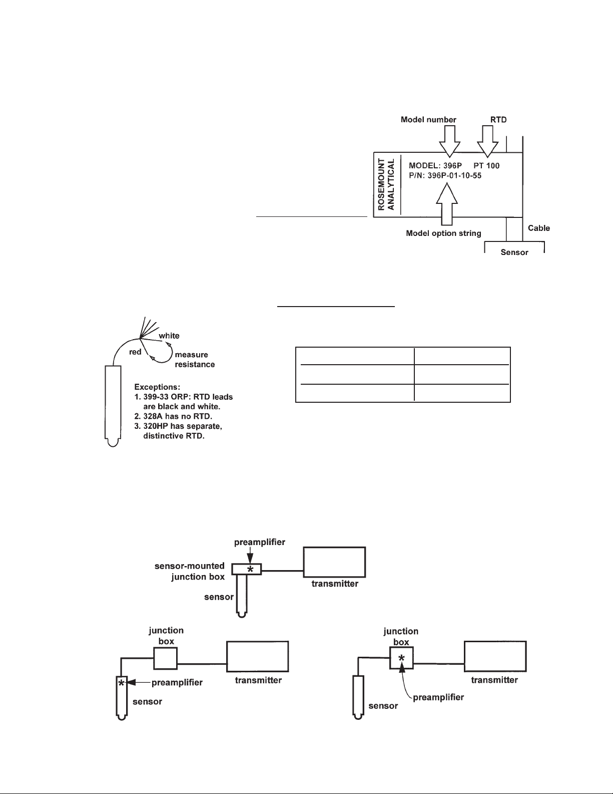
1. THE MODEL NUMBER OF THE SENSOR
• Look on the label.
• Also note the model option string.
• If the label is missing or unreadable, see the
flowcharts on pages 28 through 30.
Write the sensor model number here
2. THE TYPE OF TEMPERATURE ELEMENT
• Look on the label.
• If the label is missing or unreadable, measure the
resistance between the RTD leads.
Write the temperature element RTD here
3. THE LOCATION OF THE PREAMPLIFIER: INSIDE OR OUTSIDE THE TRANSMITTER?
• If the sensor is wired through a junction box, the preamplifier is ALWAYS in the junction box or
the sensor.
If resistance is . . . the RTD is . . .
about 110 ohms Pt 100
about 3000 ohms Balco 3K
Page 4
• If the sensor is wired directly to the transmitter, the preamplifier can be in either the sensor
or the transmitter.
• Look at the wires in the sensor cable. A GREEN wire means the preamplifier is in the sensor. An coaxial cable means the preamplifier is in the transmitter. A coaxial cable is an
insulated wire surrounded by a braided metal shield. The wire terminates in either a BNC
connector or an ORANGE wire with a CLEAR shield.
Write the preamplifier location here
CAN YOU USE THE QUICK START GUIDE
ON THE FOLLOWING PAGE?
Use the Quick Start Guide if . . .
1. you are NOT using a HART communicator,
2. you do NOT require an intrinsically safe or explosion-proof installation,
3. you are NOT measuring ORP,
4. you do NOT require transmitter setup beyond programming the 4-20 mA output,
5. you are NOT using a a sensor-mounted junction box or a remote junction box,
6. you are NOT using a sensor made by another manufacturer,
7. you are using one of the following sensors:
Note: Only the model option numbers needed to select the correct wiring diagram in the
Quick Start Guide are shown. Other model option numbers are not shown.
If you cannot use the Quick Start Guide, turn to Section 2.0 of the instruction manual.
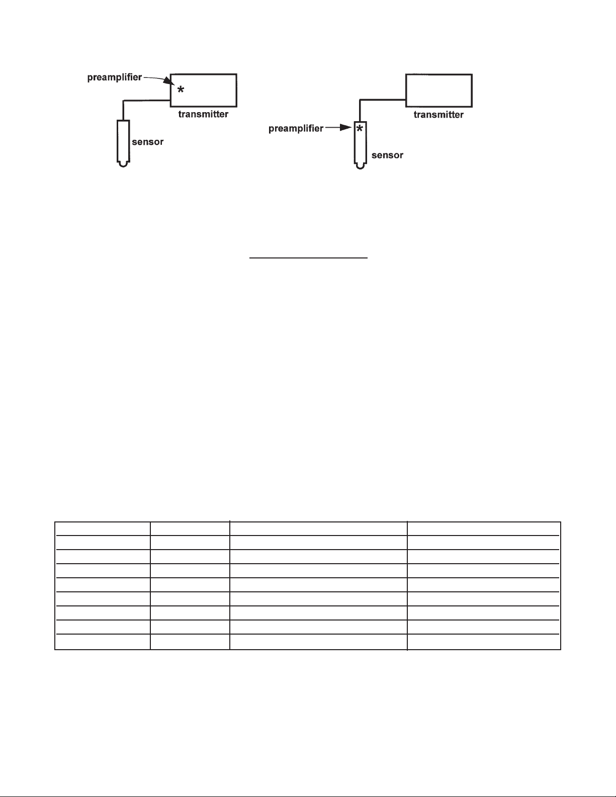
Base Model RTD Preamplifier located Model Option (note)
381+ Pt 100 in sensor (green wire) 381+ -55
381+ Pt 100 in transmitter (orange wire) 381+ -52
385+ Pt 100 in sensor (green wire) 385+ -03
385+ Pt 100 in transmitter (orange wire) 385+ -04
396P Pt 100 in transmitter (orange wire) 396P-02-54
396P Pt 100 in sensor (green wire) 396P-01-55
396P Pt 100 in transmitter (orange wire) 396P-02-55
396R Pt 100 in transmitter (orange wire) 396R-54
Page 5
QUICK START GUIDE FOR MODEL 3081pH/ORP
Before using this Quick Start Guide, please read “WHAT YOU NEED TO KNOW BEFORE
INSTALLING AND WIRING A ROSEMOUNT ANALYTICAL SENSOR TO THE MODEL 3081
pH/ORP TRANSMITTER” on the preceding page.
Section 1.1 Setup for the Models 381+-52, 385+-04, 396P-02-54, 396P-02-55 and 396R-54 without a junction box
A. The factory setting of the preamplifier switch is in the appropriate location, so no adjustment is necessary.
B. Mount the transmitter in the desired location. Most installations use PN 2002577, pipe mounting bracket.
C. Continue the start up with Section 2 Wiring.
Section 1.2 Setup for Sensor Models 381+-55, 385+-03, and 396P-01-55 without a junction box
A. This section shows how to set the preamplifier switch and should be done prior to installation of the transmitter.
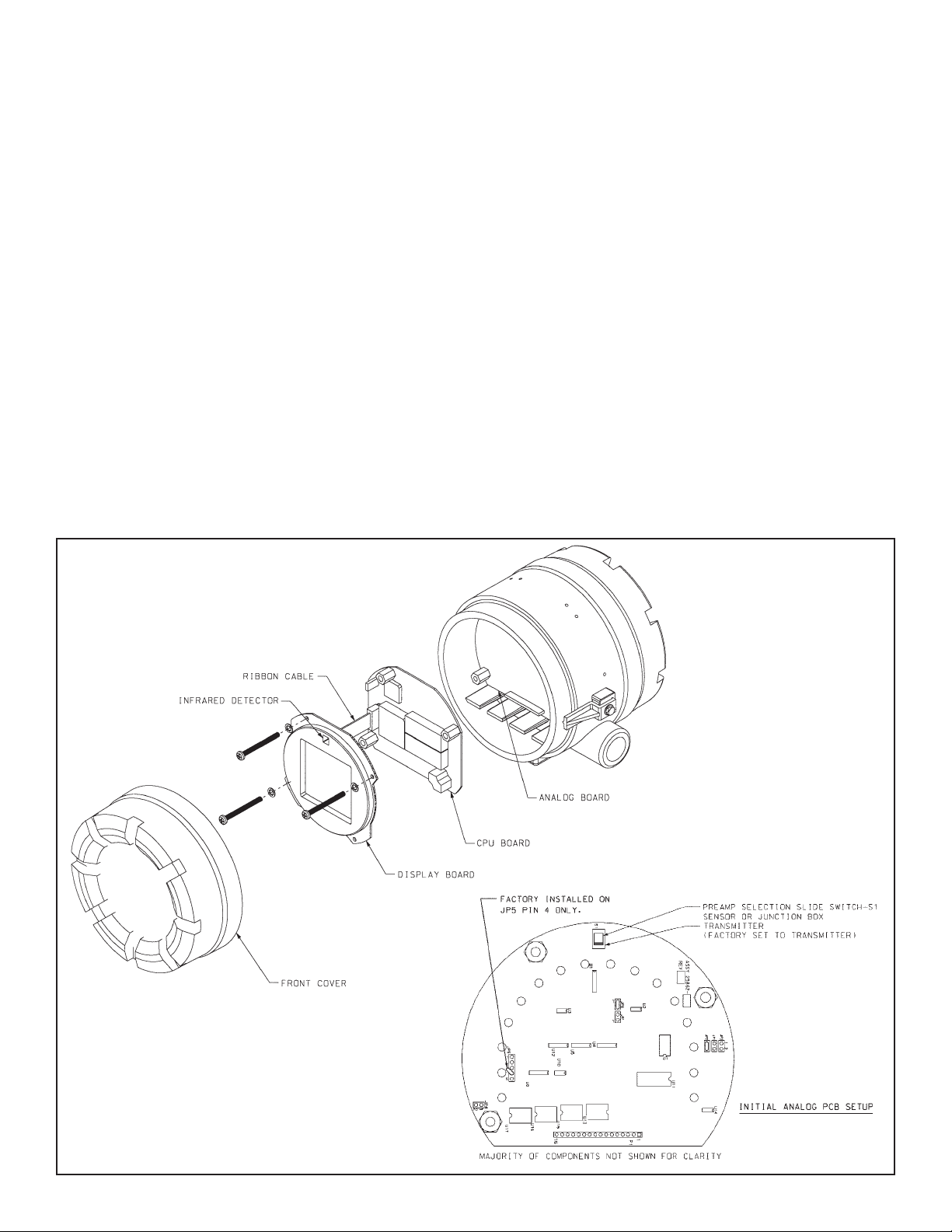
B. Loosen the cover lock nut on the Model 3081pH/ORP transmitter until the tab disengages from the circuit end cap.
Unscrew and remove the cap. Unscrew the three bolts holding the circuit board stack in the enclosure.
C. Pull up on the display board. Do not disconnect the ribbon cable between it and the CPU board. The CPU and analog
boards are joined by a pin and socket connector along the bottom edge of the boards. Carefully pull the boards apart and
remove the CPU board. The analog board is on the bottom and remains in the enclosure. See Figure 1 below.
D. The analog board is shaped like a circle with an arc missing. Directly opposite the straight side is a slide switch. Change
the switch position to the "sensor or j-box" setting by sliding the switch closer to the edge of the board. See Figure 2 below.
E. To reassemble the stack, place the display board on the CPU board. Be sure the display board is properly oriented. The
small square window (the infrared detector for the remote controller) marks the top of the board. Insert the three bolts
through the holes. Align the bolts with the standoffs on the analog board and position the display and CPU boards on the
analog board. SIf the boards are properly aligned, the bolts will drop in place. Press along the bottom of the stack to seat
the pin and socket connector. Tighten the bolts, replace the cap and cover lock nut.
F. Mount the transmitter in the desired location. Most installations use PN 2002577, pipe mounting bracket.
FIGURE 2
FIGURE 1
Page 6
Section 2 Wiring
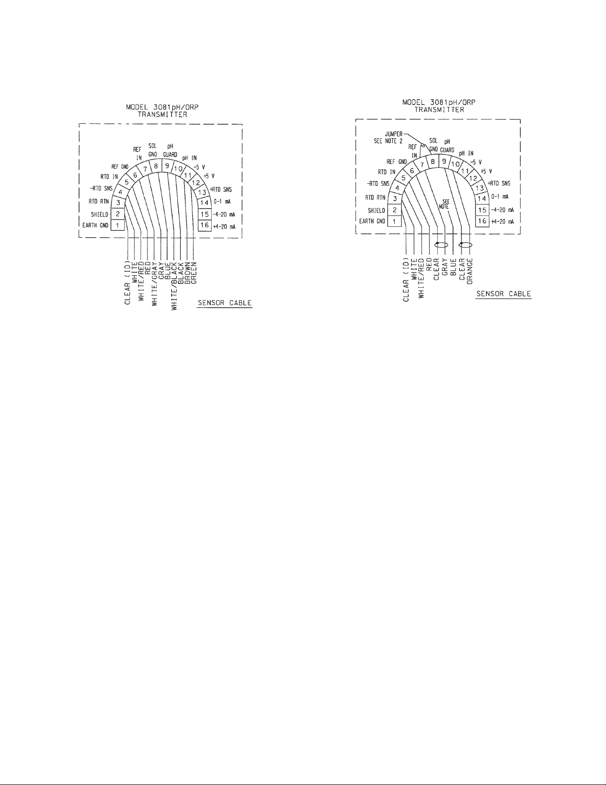
A. Wire sensor Model 381+-55, 385+-03, or 396P-01-55 directly to the transmitter as shown in Figure 3.
B. Wire sensor Model 381+-52, 385+-04, 396P-02-55, 396P-02-55, or 396R-54 as shown in Figure 4.
C. Wire the 12 - 42.4 Vdc power supply to TB-15 (- 4 - 20 mA) and TB-16 (+ 4 - 20 mA).
Section 3 Power up and Calibration
A. Apply dc power to the transmitter.
B. Remove the red protective "boot" from the sensor end. Rinse with deionized water and gently pat dry with a tissue (don't
wipe or rub). Place the pH sensor in the first buffer. Install the batteries in the remote controller.
Note: A pH measurement is only as good as the calibration, and the calibration is only as good as the buffers
used. A careful buffer calibration is the first step in making an accurate pH measurement. For best results, calibrate with buffers having the same temperature as the process. Allow time for the sensor and buffers to reach the
same temperature. If the process temperature is more than 10°°C different from the buffer, allow at least 20 minutes. Be careful using buffers at high temperatures because the pH of many buffers is undefined above 60°C. See
the main instruction manual for further information.
C. Aim the infrared remote controller (IRC) at the LCD display.
Press CAL . CALIbrAtE will appear.
Press ENTER . CAL bF1 will appear.
D. With the sensor in the first buffer, be sure the glass bulb and the temperature element are completely submerged (i.e. 3
inches). Do not let the weight of the sensor rest on the glass bulb. Swirl the sensor to dislodge trapped bubbles.
Press ENTER . bF1 will flash until reading is stable. The measured pH value will appear in the main display.
Press Ïor Ðuntil the small number next to bF1 matches the nominal pH buffer value (i.e. 4.01 pH).
Press ENTER to save the first calibration point. CAL bF2 will appear.
E. Remove the sensor from the first buffer, rinse, and place in the second buffer.
Press ENTER . bF2 will flash until the reading is stable. The measured pH value will appear in the main display.
Press Ïor Ðuntil the small number next to bF2 matches the nominal pH buffer value (i.e. 10.00 pH).
Press ENTER to save the second calibration point.
F. Press RESET to return to the process display. The calibration is complete.
G. Place the sensor in the process. The start up is complete, although the following optional procedure may be useful.
Section 4 Output (OPTIONAL)
A. This optional procedure assigns specific pH values to the 4 - 20 mA output. The factory default is set to 0.00 pH at 4 mA
and 14.00 pH at 20 mA.
Press PROG . OutPut will appear.
Press ENTER . 4 MA will appear. Use the arrow keys to change the displayed number to the desired pH.
Press ENTER to save. 20 MA will appear. Use the arrow keys to change the displayed number to the desired pH.
Press ENTER to save.
Press RESET to return to the process display.
NOTES:
1. INSTRUMENT JUMPER SUPPLIED BY CUSTOMER.
2. DO NOT CONNECT BLUE WIRE INSIDE TRANSMITTER. INSULATE STRIPPED
END OF BLUE WIRE.
FIGURE 3 FIGURE 4
Page 7

QUICK REFERENCE GUIDE
MODEL 3081PH/ORP
Automatic Buffer Calibration
Note: A pH measurement is only as good as the calibration, and the calibration is only as good as the buffers used. For best
results, calibrate with buffers having the same temperature as the process. Allow time for the sensor and buffers to reach the
same temperature. If the process temperature is more than 10°C different from the buffer, allow at least 20 minutes. Be careful
using buffers at high temperatures. The pH of many buffers is undefined above 60°C. See the main instruction manual for further information.
A. Aim the infrared remote controller (IRC) at the LCD display.
Press HOLD on the IRC. HoLd OFF will appear.
Press Ð to toggle the display to HoLd On.
Press ENTER to engage hold mode. The HOLD indicator will appear to the left of the pH value.
B. Press CAL . CALIbrAtE will appear.
Press ENTER . CAL bF1 will appear.
C. With the sensor in the first buffer, be sure the glass bulb and the temperature element are completely submerged (about 3
inches deep). Do not let the weight of the sensor rest on the glass bulb. Swirl the sensor to dislodge trapped bubbles.
Press ENTER . bF1 will flash until reading is stable. The measured pH value will appear in the main display.
Press Ïor Ðuntil the small number next to bF 1 matches the nominal pH buffer value (i.e., 4.01 pH).
Press ENTER to save the first calibration point. CAL bF2 will appear.
D. Remove the sensor from the first buffer, rinse and place in the second buffer.
Press ENTER . bF2 will flash until the reading is stable.
Press Ïor Ðuntil the small number next to bF 2 matches the nominal pH buffer value (i.e., 10.00 pH).
Press ENTER to save the second calibration point.
E. The calibration is complete, but the transmitter remains in the CALIbrAtE sub-menu for two minutes after ENTER is
pressed. Press RESET to return to the process display immediately.
F. Place sensor in the process.
G. (Optional) For maintenance purposes, track the slope of the pH electrode. The slope value of a new electrode is 59mV
per pH unit, and this value falls over time. The sensor should be changed when the slope nears 47.5mV per pH. To view
the slope value, use the following steps.
Press CAL . CALIbrAtE will appear.
Press NEXT . Std will appear.
Press ENTER . The current pH value will appear next to Std.
Press ENTER . SLOPE and the current slope value will appear. Record this number as the slope value.
Press RESET to return to the process display.
H. After calibration, press HOLD . HoLd On will display.
Press Ðto toggle the display to HoLd Off. Press ENTER to save this into memory.
The HOLD indicator on the display will turn off.
Standardizing to Match a Reference Instrument
Note: Standardization does not perform a true calibration. Regular buffer calibrations are still needed to update the sensor
slope value. For best results take the grab sample from a point as close as possible to the pH sensor and measure the sample
at the same temperature as the process.
A. Aim the infrared remote controller (IRC) at the LCD display.
Press HOLD on the IRC. HoLd OFF will appear.
Press Ðto toggle the display to HoLd On.
Press ENTER to engage the hold mode. The HOLD indicator will appear to the left of the pH value.
B. Press CAL . CALIbrAtE will appear.
Press NEXT . Std will appear.
Press ENTER . The measured value will appear.
C. Take a grab sample of the process and measure it with your reference instrument. Use the editing keys to adjust the value
on the Model 3081pH/ORP to match the reference instrument. Press ENTER to save the corrected pH value.
D. If the value is acceptable, the sensor slope is displayed. The slope has not been changed.
E. Press RESET to return to the process display.
F. After calibration, press HOLD . HoLd On will display.
Press Ðto toggle the display to HoLd Off. Press ENTER to save this into memory.
The HOLD indicator on the display will turn off.
Page 8
HART Communicator Fast Key Sequences
Technical Support Hotline:
For assistance with technical problems, please call the Customer Support Center (CSC). The CSC is staffed from
5:00am to 5:00pm PST.
Phone (US only): 800-854-8257 Phone: 949-757-8500
Fax: 949-863-9159 World Wide Web: www.raihome.com
PROGRAM
CALIBRATE
OutPut
GIMP 1000 V Er 81PH.21
tEMP 25 C
InPut 58.9 ShoW FLt
nonE
rIMP 10
dIAGnOStIC tEMP
bUFFErdISPLAY ISOPOtntAL
SIM OUtPUt
CALIbrAtE
Std
tEMP AdJ
tEMP 25.0
4 MA 00.00
20MA 14.00
HoLd 21.00
FAULt 22.00
dPn 0.00
tAUtO On
tMAn 25.0
tC 100-3
tYPE PH
tEMP C
OUtPUt Cur
COdE 000
bAUtO On
bUFFEr Std
tIME 10
PH 00.02
tCOEF 00.00
ISO 07.00
Snr 07.00
tESt 12.00
rOFFSt 060
dIAG OFF
IMPtC ON
GWH 1000
GFH 1500
GWL 020
GFL 010
CAL 000
rEF LO
rFH 140
rWH 040
rWL 000
rFL 000
CAL bF1
bF 1
bF1 4.01
CAL bF2
bF 2
bF2 10.01
DIAGNOSE
Std 7.00
SLOPE 59.01
MENU
Sub-menu
PROMPT
Diag Message
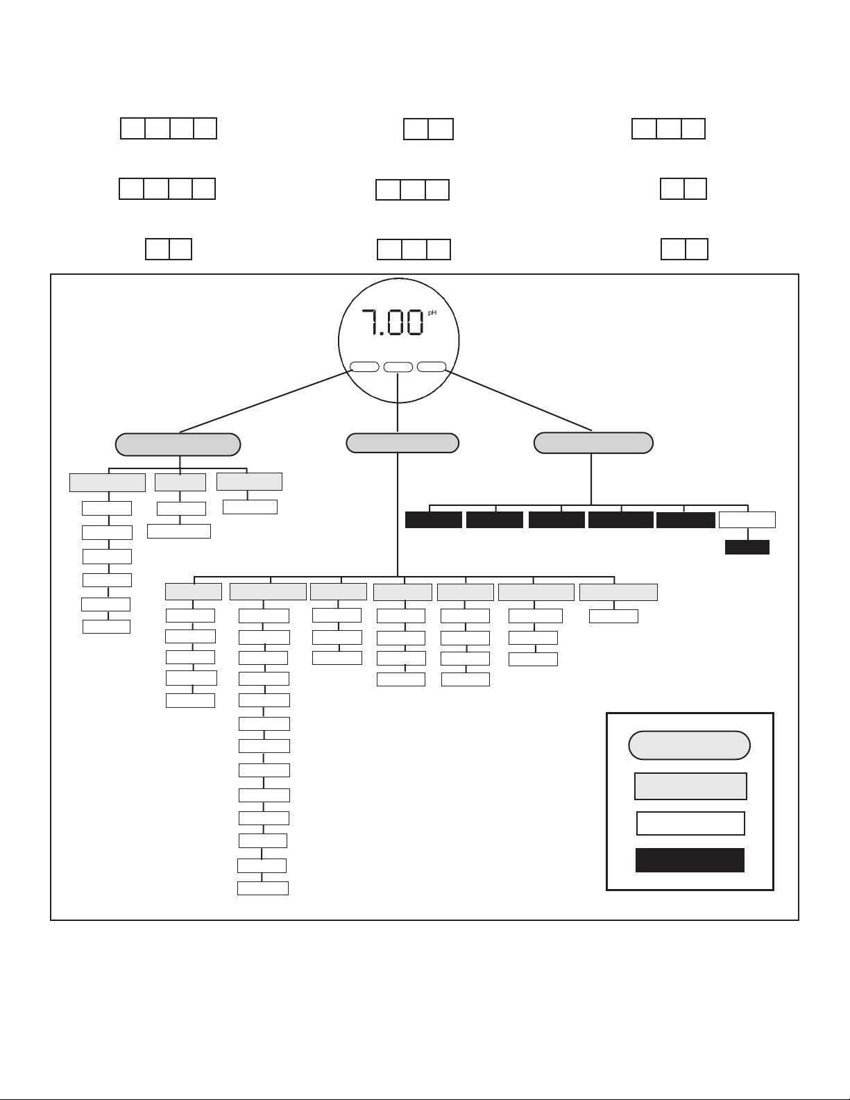
Menu Tree for pH
Buffer Calibration
2311
Standardize
2321
Trim Analog Output
24
Toggle Hold Mode
25
pH Upper Range Value
322
pH Lower Range Value
321
View pH value
111
View Analog Output
12
View Transmitter Status
13
Page 9

i
MODEL 3081 pH/ORP TABLE OF CONTENTS
MODEL 3081 PH/ORP
MICROPROCESSOR TRANSMITTER
TABLE OF CONTENTS
Section Title Page
1.0 DESCRIPTION AND SPECIFICATIONS ................................................................ 1
1.1 Features................................................................................................................... 1
1.2 Accessories.............................................................................................................. 2
1.3 Specifications - General for Model 3081 pH/ORP.................................................... 3
1.4 Specifications - pH................................................................................................... 4
1.5 Specifications - ORP................................................................................................ 4
1.6 Ordering Information ............................................................................................... 4
2.0 INSTALLATION....................................................................................................... 7
2.1 Unpacking and Inspection........................................................................................ 7
2.2 Pre-Installation Set Up............................................................................................. 7
2.3 Orienting the Display Board..................................................................................... 10
2.4 Mechanical Installation............................................................................................. 10
2.5 Power Supply/Current Loop..................................................................................... 13
3.0 WIRING.................................................................................................................... 14
3.1 General Information................................................................................................. 14
3.2 Wiring Diagrams for pH and ORP Sensors.............................................................. 15
4.0 INTRINSICALLY SAFE AND EXPLOSION PROOF............................................... 31
4.1 Intrinsically Safe Installations................................................................................... 31
4.2 Explosion Proof Installations.................................................................................... 31
5.0 OPERATION WITH REMOTE CONTROLLER ....................................................... 37
5.1 Displays ................................................................................................................... 37
5.2 Infrared Remote Controller (IRC)............................................................................. 38
5.3 Menu Tree - pH........................................................................................................ 39
5.4 Diagnostic Messages - pH....................................................................................... 39
5.5 Menu Tree - ORP..................................................................................................... 40
5.6 Diagnostic Messages - ORP.................................................................................... 40
5.7 Security.................................................................................................................... 41
6.0 OPERATION WITH MODEL 275............................................................................. 42
6.1 Note on Model 275 HART Communicator................................................................ 42
6.2 Connecting the HART Communicator...................................................................... 42
6.3 Operation................................................................................................................. 43
7.0 CALIBRATION OF pH MEASUREMENTS............................................................. 48
7.1 General.................................................................................................................... 48
7.2 Entering and Leaving the Calibrate Menu................................................................ 48
7.3 Using the Hold Function........................................................................................... 48
7.4 Temperature Calibration........................................................................................... 49
7.5 Auto Calibration ....................................................................................................... 50
7.6 Manual Calibration................................................................................................... 52
7.7 Making the Transmitter Reading Match a Second pH Meter (Standardization)....... 54
Page 10

MODEL 3081 pH/ORP TABLE OF CONTENTS
TABLE OF CONTENTS CONT’D
ii
8.0 PROGRAMMING FOR pH MEASUREMENTS....................................................... 56
8.1 General.................................................................................................................... 56
8.2 Entering and Leaving the Program Menu................................................................ 56
8.3 Output Ranging........................................................................................................ 58
8.4 Diagnostic Parameters............................................................................................. 60
8.5 Temperature Related Settings ................................................................................. 64
8.6 Display Units............................................................................................................ 66
8.7 Buffer Calibration Parameters.................................................................................. 67
8.8 Isopotential Parameters........................................................................................... 69
8.9 Generating a Test Current........................................................................................ 71
9.0 CALIBRATION OF ORP MEASUREMENTS .......................................................... 72
9.1 General.................................................................................................................... 72
9.2 Entering and Leaving the Calibrate Menu................................................................ 72
9.3 Using the Hold Function........................................................................................... 72
9.4 Temperature Calibration........................................................................................... 73
9.5 Standardization........................................................................................................ 74
10.0 PROGRAMMING FOR ORP MEASUREMENTS.................................................... 75
10.1 General.................................................................................................................... 75
10.2 Entering and Leaving the Program Menu................................................................ 75
10.3 Output Ranging........................................................................................................ 77
10.4 Diagnostic Parameters............................................................................................. 79
10.5 Temperature Element............................................................................................... 82
10.6 Display Units............................................................................................................ 83
10.7 Generating a Test Current........................................................................................ 84
11.0 MAINTENANCE ...................................................................................................... 85
11.1 Overview.................................................................................................................. 85
11.2 Transmitter Maintenance ......................................................................................... 85
11.3 pH Sensor Maintenance.......................................................................................... 86
11.4 ORPSensor Maintenance ....................................................................................... 87
11.5 Calibration................................................................................................................ 88
12.0 TROUBLESHOOTING ........................................................................................... 89
12.1 Warning and Fault Messages.................................................................................. 89
12.2 Calibration Errors..................................................................................................... 90
12.3 Troubleshooting - General....................................................................................... 90
12.4 Troubleshooting When a Diagnostic Message is Showing...................................... 90
12.5 Troubleshooting When No Diagnostic Message is Showing.................................... 102
12.6 Systematic Troubleshooting..................................................................................... 107
12.7 Displaying Diagnostic Variables............................................................................... 110
12.8 Testing the Transmitter by Simulating pH................................................................ 110
12.9 Factory Assistance and Repairs .............................................................................. 113
Page 11

iii
MODEL 3081 pH/ORP TABLE OF CONTENTS
TABLE OF CONTENTS CONT’D
13.0 pH MEASUREMENTS............................................................................................. 114
13.1 General.................................................................................................................... 114
13.2 Measuring Electrode................................................................................................ 115
13.3 Reference Electrode................................................................................................ 115
13.4 Liquid Junction Potential.......................................................................................... 116
13.5 Converting Voltage to pH......................................................................................... 116
13.6 Glass Electrode Slope ............................................................................................. 117
13.7 Buffers and Calibration ............................................................................................ 117
13.8 Isopotential pH......................................................................................................... 118
13.9 Junction Potential Mismatch.................................................................................... 118
13.10 Sensor Diagnostics.................................................................................................. 119
13.11 Shields, Insulation, and Preamplifiers...................................................................... 119
14.0 ORP MEASUREMENTS.......................................................................................... 120
14.1 General.................................................................................................................... 120
14.2 Measuring Electrode................................................................................................ 121
14.3 Reference Electrode................................................................................................ 121
14.4 Liquid Junction Potential.......................................................................................... 121
14.5 Relating Cell Voltage to ORP................................................................................... 122
14.6 ORP, Concentration, and pH.................................................................................... 122
14.7 Interpreting ORP Measurements ............................................................................. 123
14.8 Calibration................................................................................................................ 124
15.0 THEORY - REMOTE COMMUNICATIONS............................................................. 126
15.1 Overview of HART Communications........................................................................ 126
15.2 HART Interface Devices........................................................................................... 126
15.3 AMS Communication............................................................................................... 127
16.0 GLOSSARY............................................................................................................. 128
17.0 RETURN OF MATERIAL......................................................................................... 134
Page 12

iv
MODEL 3081 pH/ORP TABLE OF CONTENTS
TABLE OF CONTENTS CONT’D
LIST OF FIGURES
Number Title Page
2-1 Model 3081 pH/ORP Transmitter - Exploded Drawing of Circuit Board Stack......... 8
2-2 Model 3081 pH/ORP Transmitter - Analog Board .................................................... 9
2-3 Model 3081 pH/ORP Transmitter - CPU Board........................................................ 10
2-4 Mounting the Model 3081 pH/ORP Transmitter on a Flat Surface........................... 11
2-5 Using the Pipe Mounting Kit to Attach the Model 3081 pH/ORPTransmitter to a Pipe . 12
2-6 Load/Power Supply Requirements .......................................................................... 13
2-7 Power Supply/Current Loop Wiring.......................................................................... 13
3-1 Wiring and Preamplifier Configurations for pH and ORP Sensors........................... 14
3-2 Wire Functions for Models 399-02, 399-09, 381pH-30-41, and 381pHE-31-41.......
before removing BNC and terminating cable ........................................................... 18
3-3 Wire Functions for Models 399-02, 399-09, 381pH-30-41, and 381pHE-31-41.......
after removing BNC and terminating cable. Wire Functions for Models ..................
399-09-10-62, 381pH-30-42, and 381pHE-31-42 as received................................. 18
3-4 Wiring Diagram for Models 399-02, 399-09, 381pH-30-41, and 381pHE-31-41 after
removing BNC and terminating cable. Wiring Diagram for Models ..399-09-10-62,
381pH-30-42, and 381pHE-31-42 as received. Wiring directly to the transmitter.... 18
3-5 Wiring Diagram for Models 399-02, 399-09, 381pH-30-41 after removing BNC and
terminating cable. Wiring Diagram for Model 399-09-10-62, 381pH-30-42, and .....
381pHE-31-42 as received. Wiring through a remote junction box to the transmitter. 18
3-6 Wire Functions for Models 397-50, 397-54, 396-50, 396-54, 396R-50-60, 396R-54-60,
389-02-50, and 389-02-54 before removing BNC and terminating cable................. 19
3-7 Wire Functions for Models 397-50, 397-54, 396-50, 396-54, 396R-50-60, 396R-54-60,
389-02-50, and 389-02-54 after removing BNC and terminating cable. Wire .........
Functions for Models 397-54-62, 396-54-62, and 389-02-54-62 as received.......... 19
3-8 Wiring Diagram for Models 397-50, 397-54, 396-50, 396-54, 389-02-50, and.........
389-02-54 after removing BNC and terminating cable. Wiring Diagram for ............
Models 397-54-62, 396-54-62, and 389-02-54-62 as received. Wiring Directly.......
to the Transmitter ................................................................................................... 19
3-9 Wiring Diagram for Models 397-50, 397-54, 396-50, 396-54, 396R-50-60, 396R-54-60,
389-02-50, and 389-02-54 after removing BNC and terminating cable. Wiring ......
Diagram for Models 397-54-62, 396-54-62, and 389-02-54-62 as received. ..........
Wiring Through a Remote Junction Box to the Transmitter ..................................... 19
3-10 Wire Functions for Models 396R-50, 396R-54, 396R-54-61, 396P-02-50,..............
396P-02-54, 396P-02-55, 385+-04, and 381+-41-52............................................... 20
3-11 Wiring Diagram for Models 396R-50, 396R-54, 396R-54-61, 396P-02-50, 396P-02-54,
396P-02-55, 385+-04, and 381+-41-52. Wiring Directly to the Transmitter ............ 20
3-12 Wiring Diagram for Models 396R-50, 396R-54, 396R-54-61, 396P-02-50, .............
396P-02-54, 396P-02-55, 385+-04, and 381+-41-52. Wiring Through a Sensor-....
Mounted Junction Box to the Transmitter ................................................................ 20
3-13 Wire Functions for Models 396P-01-55, 385+-03, 381+-40-55, and 381+-43-55 .... 21
3-14 Wiring Diagram for Models 396P-01-55, 385+-03, 381+-40-55, and 381+-43-55.... 21
3-15 Wire Functions for Model 385+-02........................................................................... 22
3-16 Wiring Diagram for Model 385+-02 .......................................................................... 22
3-17 Wire Functions for Model 328A-07........................................................................... 23
3-18 Wiring Diagram for Model 328A............................................................................... 23
3-19 Wiring Diagram for Model 320HP-10-55.................................................................. 24
3-20 Wiring Diagram for Model 320HP-10-58.................................................................. 24
3-21 Wire Functions for Model 399-33............................................................................. 25
3-22 Wiring Diagram for Model 399-33 ............................................................................ 25
Page 13

v
MODEL 3081 pH/ORP TABLE OF CONTENTS
TABLE OF CONTENTS - CONT’D
LIST OF FIGURES - CONT’D
Number Title Page
3-23 Procedure for Removing BNC Connector and Preparing Coaxial Cable for............
Connection to the Model 3081 pH/ORP Transmitter................................................ 26
3-24 Preparation of Raw Connecting Cable (PN 9200273).............................................. 27
4-1 Intrinsically Safe BASEEFAModel 3081 pH/ORP Label .......................................... 31
4-2 FMRC Installation for Model 3081 pH/ORP Transmitter........................................... 32
4-3 CSAInstallation for Model 3081 pH/ORP Transmitter.............................................. 34
4-4 Explosion-Proof Installation for Model 3081 pH/ORP Transmitter............................ 36
5-1 Process Display Screen........................................................................................... 37
5-2 Program Display Screen .......................................................................................... 37
5-3 Infrared Remote Controller....................................................................................... 38
5-4 Menu Tree for pH..................................................................................................... 39
5-5 Menu Tree for ORP ................................................................................................. 40
6-1 Connecting the HART Communicator ...................................................................... 42
6-2 Menu Tree for pH (HART) ........................................................................................ 44
6-3 Menu Tree for ORP(HART)..................................................................................... 46
8-1 Suggested Glass Impedance Warning and Failure Limits ....................................... 60
8-2 Suggested Warning and Failure Limits for Low Impedance Reference Electrodes. 61
8-3 Suggested Warning and Failure Limits for High Impedance Glass Reference .......
Electrodes ................................................................................................................ 61
10-1 Suggested Warning and Failure Limits for Low Impedance Reference Electrodes. 79
10-2 Suggested Glass Impedance Warning and Failure Limits for a Glass Reference....
Electrode.................................................................................................................. 79
11-1 Exploded View of Model 3081 pH/ORP Transmitter................................................. 85
11-2 Checking the Potential of the Reference Electrode.................................................. 87
12-1 Warning Annunciation............................................................................................... 89
12-2 Fault Annunciation.................................................................................................... 89
12-3 Three-Wire RTD .................................................................................................... 96
12-4 Temperature Simulation into the Model 3081 pH/ORP Transmitter ......................... 97
12-5 Troubleshooting Flow Chart/Preamplifier in Sensor-Mounted Junction Box or........
Remote Junction Box............................................................................................... 108
12-6 Troubleshooting Flow Chart/Preamplifier in Transmitter or Built into Sensor........... 109
12-7 pH Simulation When the Preamplifier is Located in the Transmitter........................ 111
12-8 pH Simulation When the Preamplifier is Located in a Remote Junction Box or.......
in a Sensor-Mounted Junction Box .......................................................................... 111
12-9 Simulate pH Through Model 381+ Sensor Preamplifier........................................... 112
13-1 pH Measurement Cell............................................................................................... 114
13-2 Measuring Electrode (pH) ........................................................................................ 115
13-3 Cross-Section Through the pH Glass....................................................................... 115
13-4 Reference Electrode................................................................................................. 116
13-5 The Origin of Liquid Junction Potential..................................................................... 116
13-6 Glass Electrode Slope.............................................................................................. 117
13-7 Two-Point Buffer Calibration..................................................................................... 118
13-8 Liquid Junction Potential Mismatch.......................................................................... 119
14-1 ORP Measurement Cell ........................................................................................... 120
14-2 Measuring Electrode (ORP)..................................................................................... 121
14-3 Reference Electrode................................................................................................. 121
14-4 The Origin of Liquid Junction Potential..................................................................... 122
14-5 Electrode Potential................................................................................................... 122
14-6 ORP Measurement Interpretation............................................................................. 123
15-1 HART Communications ........................................................................................... 126
15-2 AMS Main Menu Tools ............................................................................................. 127
Page 14

vi
MODEL 3081 pH/ORP TABLE OF CONTENTS
TABLE OF CONTENTS CONT’D
LIST OF TABLES
Number Title Page
3-1 Wiring Diagrams for Model 399 Sensors.................................................................. 15
3-2 Wiring Diagrams for Model 397 Sensors.................................................................. 15
3-3 Wiring Diagrams for Model 396R Sensors............................................................... 15
3-4 Wiring Diagrams for Model 396P Sensors ............................................................... 16
3-5 Wiring Diagrams for Model 396 Sensors.................................................................. 16
3-6 Wiring Diagrams for Model 389 Sensors.................................................................. 16
3-7 Wiring Diagrams for Model 385+ Sensors................................................................ 17
3-8 Wiring Diagrams for Model 381+ Sensors................................................................ 17
3-9 Wiring Diagrams for Model 381pHE and 381pH Sensors........................................ 17
3-10 Wiring Diagrams for Model 328ASensors ............................................................... 17
3-11 Wiring Diagrams for Model 320HP Sensors............................................................. 17
8-1 pH Settings List ....................................................................................................... 57
8-2 pH Values of Standard Buffer Solutions and the Temperature Range over which ...
pH Values are Defined ............................................................................................. 67
8-3 pH Values of Commercial (technical) Buffers and the Temperature Range over .....
which pH Values are Defined .................................................................................. 68
8-4 Standard and Technical Buffers Recognized by the Model 3081 pH Transmitter .... 68
10-1 ORP Settings List .................................................................................................... 76
11-1 Replacement Parts for Model 3081 pH Transmitter ................................................ 86
12-1 RTD Resistance Values ........................................................................................... 96
Page 15

1
MODEL 3081 pH/ORP SECTION 1.0
DESCRIPTION AND SPECIFICATIONS
SECTION 1.0
DESCRIPTION AND SPECIFICATIONS
1.1 Features
1.2 Accessories
1.3 Specifications - General for Model 3081 pH/ORP
1.4 Specifications - pH
1.5 Specifications - ORP
1.6 Ordering Information
• CHANGING FROM pH TO ORP operation takes only seconds.
• REMOTE COMMUNICATION IS SIMPLE; use the hand-held infrared remote controller or any
HART® compatible device.
• LARGE TWO LINE DISPLAY shows pH or ORP, temperature, and output signal.
• SIMPLE, INTUITIVE MENUS make programming and calibrating easy.
• AUTOMATIC TWO-POINT BUFFER CALIBRATION reduces errors.
• SOLUTION TEMPERATURE COMPENSATION converts measured pH to the pH at 25°C.
• CONTINUOUS DIAGNOSTICS monitor sensor performance and warn the user of failure (FAULT)
or approaching failure (WARNING).
• ROBUST NEMA 4X ENCLOSURE protects the transmitter from harsh plant environments.
• INTRINSICALLY SAFE DESIGN allows the transmitter to be used in hazardous environments (with
appropriate safety barriers).
• NON-VOLATILE EEPROM MEMORY retains program settings and calibration data during power
failures.
1.1 FEATURES
APPLICATION: The Model 3081pH/ORP Transmitter
with the appropriate pH or ORP sensor measures pH
between 0 and 14 and ORP between -1400 and 1400
millivolts. Converting the transmitter from a pH instrument to an ORP instrument takes only seconds.
REMOTE COMMUNICATIONS: Remote communications with the Model 3081 pH/ORP transmitter is easy.
The hand-held, push button infrared remote controller
works from as far away as six feet. The transmitter also
belongs to the Rosemount SMART FAMILY®, so it
works with the Model 275 HART® hand-held communicator or with any host that supports the HART protocol.
DISPLAY: The 0.8-inch high LCD main display means
pH and ORP values are easy to read even at a distance.
Secondary variables, temperature and current output,
appear in a 0.3 inch high display.
MENUS: Menu formats for calibration and programming
are simple and intuitive. Prompts guide the user through
the basic procedures. Diagnostic and error messages
appear in plain language. There are no annoying codes
to look up.
Page 16

2
CALIBRATION: Two-point, temperature-corrected buffer
calibration is standard. To reduce errors caused by
impatient operators, the Model 3081 pH/ORP transmitter
does not accept calibration data until programmed stability limits have been met. If data are not acceptable, the
transmitter displays an error message and does not
update the calibration. The transmitter recognizes every
buffer scale in common use in the world. Manual twopoint and one-point calibration are also available.
AUTOMATIC TEMPERATURE COMPENSATION:
Temperature compensation is completely automatic. The
Model 3081 pH/ORP transmitter is compatible with two,
three, and four wire Pt 100, Pt 1000, and 3K Balco
RTDs.
SOLUTION TEMPERATURE COMPENSATION: The
Model 3081 pH transmitter features solution temperature
compensation. The transmitter calculates and displays
the pH at 25°C from the pH measured at any temperature. The temperature coefficient of the liquid being
measured must be known.
SENSOR DIAGNOSTICS: Continuous diagnostics alert
the user to impending or existing sensor failure.
Diagnostic messages in plain language aid in troubleshooting. The manual contains a thorough, step-bystep troubleshooting guide.
HOUSING: The Model 3081 pH/ORP transmitter housing meets NEMA 4X standards. The transmitter tolerates
outdoor and harsh plant environments. The housing also
meets NEMA7B explosion-proof standards.
HAZARDOUS AREA INSTALLATION: Circuits in the
Model 3081 pH/ORP transmitter are designed and built
to be intrinsically safe when used with the appropriate
safety barrier.
OUTPUT: The 4 to 20 mA output signal is fully
adjustable between 0 and 14 pH and between -1400
and 1400 mV. During hold and fault conditions the output can be programmed to remain at the last value or go
to any value between 3.8 and 22 mA.
1.2 ACCESSORIES
1.2.1 Power Supply. Use the Model 515 Power Supply
to provide the dc loop power required by the Model 3081
pH/ORP transmitter. The Model 515 provides either a
single source of power at 48 Vdc and 200 mA or two isolated sources at 24 Vdc and 200 mA each. A junction
box (PN 2002188) allows as many as nine 3081
pH/ORP transmitters to be powered from each output.
For more information refer to product data sheet 71-515.
1.2.2 Alarm Module. The Model 230A Alarm Module
receives the 4-20 mA signal from the Model 3081
pH/ORP transmitter and activates two alarm relays.
Specify alarm configuration at the time of ordering.
High/high, low/low, and high/low are available. Dead
band is adjustable as high as 15% of full scale. For more
information, refer to product data sheet 71-230A.
1.2.3 Model 275 HART® COMMUNICATOR. The Model
3081 pH/ORP transmitter is compatible with the Model
275 HART communicator. The HART Communicator
allows the user to view pH or ORP, temperature, and
current output. The user can also program and configure
the transmitter and can download data for transfer to
another transmitter or computer. The Model 275 communicator attaches to any wiring terminal across the output
loop. A250 ohm load must be between the power supply
and the transmitter. Order the Model 275 communicator
from Rosemount Measurement. Call (800) 999-9307.
Year 2000 Compliance: Millennium Status
Rosemount Analytical , Uniloc Division, certifies that all
instruments designed and manufactured by the Uniloc
Division, do not have calendars. No instruments manufactured by Uniloc Division keep track of days, months,
or years. This has been validated by reviewing all test
and calibration procedures. In calibrating and setting up
instruments for shipping, there is no step in any procedure to enter a date.
MODEL 3081 pH/ORP SECTION 1.0
DESCRIPTION AND SPECIFICATIONS
Page 17
3
MODEL 3081 pH/ORP SECTION 1.0
DESCRIPTION AND SPECIFICATIONS
minimum voltage and load
for HART communication
1.3 SPECIFICATIONS -GENERAL
FOR MODEL 3081 pH/ORP
Case: Cast aluminum containing less than 8% magnesium.
NEMA 4X (IP65), NEMA 7 (explosion-proof)
Epoxy-polyester paint, Neoprene O-ring seals
Dimensions: 6.3 in. x 6.9 in. x 6.4 in. (160 mm x 175 mm x
161 mm); diameter 6.1 in (155 mm)
Conduit Openings: 3/4 in. FNPT
Reference Impedance: Transmitter accepts high impedance
(i.e. glass) reference electrodes as well as low impedance
(i.e. silver-silver chloride) reference electrodes.
Output: Two-wire 4-20 mAoutput with superimposed HART
digital signal.
Output can be programmed to go to any value between
3.8 and 22.0 mA to indicate a fault or hold condition.
Response Time: Display reaches 95% of final reading within
10 seconds.
Temperature Sensors: The following RTDs can be used with
the Model 3081 pH/ORP transmitter:
3 and 4 wire Pt 100 RTDs
3 and 4 wire Pt 1000 RTDs
3000 ohm Balco RTD
Transmitter can also be used with two-wire RTDs.
Temperature Range: 5°F to 248°F (-15°C to 120°C)
Local Display: Two line LCD; first line shows process vari-
able (pH or ORP), second line shows temperature and
output signal. When triggered, fault and warning messages alternate with temperature and output readings.
Process variable: 7 segment LCD, 0.8 in. (20 mm) high
Temperature/output: 7 segment LCD, 0.3 in. (7 mm) high
Display board can be rotated 90 degrees clockwise or
counterclockwise.
During calibration and programming, messages and
prompts appear in the temperature/output area.
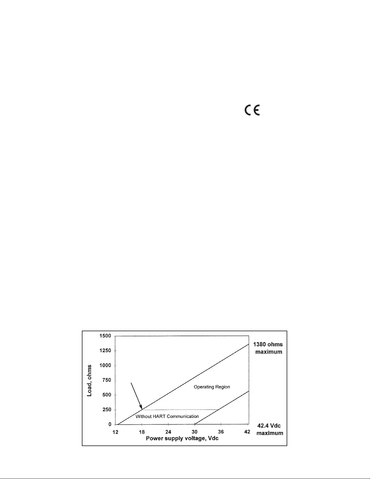
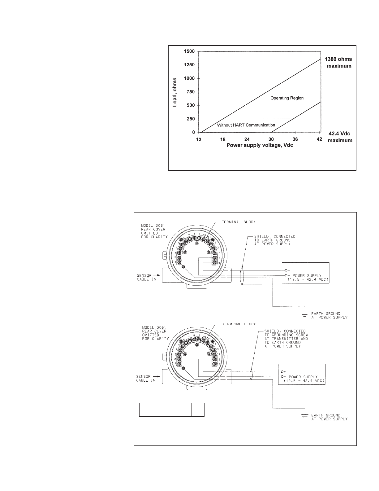
Power Supply and Load Requirements: See graph below.
A minimum loop resistance of 250 Ω and a minimum
power supply voltage of 18 Vdc is required for HART
communication. Maximum power supply voltage for
intrinsically safe and explosion-proof operation is 42.4
Vdc.
Security: User selected security code prevents
accidental changes to program settings.
Ambient Temperature: -4 to 149°F (-20 to 65°C)
Relative Humidity: 0 to 95% (with covers sealed)
Storage Temperature: -22 to 176°F (-30 to 80°C)
EMI/RFI: Meets the requirements of
EN50081-1
EN50081-2
Hazardous Area Classification:
Explosion Proof:
FM: Class I, Div. 1, Groups B, C & D
Class II, Div. 1, Groups E, F, & G
Class III, Div. 1
CSA: Class I, Div. 1, Groups C& D
Class I, Div. 2, Groups A, B, C & D
Class II, Div. 2, Groups E, F & G
Class III, Div. 1
Intrinsic Safety:
FM: Class I, II & III, Div. 1
T4 T AMB= 40°C; T3AT AMB= 70°C
CSA: Class I, Div. 1
T 3C T AMB=40°C; T3 T AMB=80°C
CENELEC: EEx ia IIC
T5 Tamb=40°C; T4 Tamb=65°C
Non-Incendive:
FM: Class I, Div. 2, Groups A, B, C & D
CSA: Class I, Div. 2, Groups A, B, C & D T5
(Tamb=40°C)
Weight/Shipping Weight: 10 lb/10 lb (4.5 kg/4.5 kg).
Weights and shipping weights are rounded to the nearest
whole pound.
Page 18

4
MODEL 3081 pH/ORP SECTION 1.0
DESCRIPTION AND SPECIFICATIONS
1.6 ORDERING INFORMATION
The Model 3081 pH/ORP Smart two-wire microprocessor transmitter is housed in a NEMA 4X case. Communication with
the transmitter is through a hand-held infrared remote controller, a Model 275 HART communicator, or any HART compatible device. Automatic temperature compensation is standard, and the transmitter can be programmed to convert measured pH to pH at 25°C (solution temperature compensation). Continuous sensor diagnostics are standard.
3081pH - 01 - 20 - 67 EXAMPLE
MODEL
3081pH/ORP HART SMART TWO-WIRE MICROPROCESSOR TRANSMITTER
Code REQUIRED SELECTION
01-20 LCD (Infrared Remote Control - included)
01-21 LCD (Infrared Remote Control - not included)
Code AGENCY APPROVALS
67 FM approved, intrinsically safe when used with approved sensor and safety barrier, explosion-proof
69 CSA approved, intrinsically safe when used with approved sensor and safety barrier, explosion-proof
73 CENELEC approved, intrinsically safe, safety barrier required
1.4 SPECIFICATIONS - pH
pH Input Range: 0 to 14 pH
Temperature Input Range: 5°F to 248°F (-15°C to 120°C)
Output Scale Expansion: Continuously expandable
between pH 0 and 14
Accuracy at 25°C: ±0.01 pH
Repeatability at 25°C: ±0.01 pH
Resolution: 0.01 pH and 0.1°C or °F
Stability at 25°C: 0.25% per year
Temperature Compensation: Automatic or manual
between 5°F to 248°F (-15°C to 120°C)
Solution Temperature Compensation: Transmitter will
convert pH measured at any temperature to the pH at
25°C. Temperature coefficient is programmable
between -0.044 pH/°C and 0.028 pH/°C
Calibration: Automatic two-point and manual two-point
buffer calibration. For automatic calibration, the transmitter recognizes NIST, DIN 19266 and 19267,
JIS 8802, BSM, Merck, and Ingold buffers.
1.5 SPECIFICATIONS - ORP
ORP Input Range: -1400 to 1400 mV
Temperature Input Range: 5°F to 248°F (-15°C to 120°C)
Output Scale Expansion: Continuously expandable
between -1400 and 1400 mV
Accuracy at 25°C: ±1 mV
Repeatability at 25°C: ±1 mV
Resolution: 1 mV and 0.1°C or °F
Stability at 25°C: 0.25% per year
Page 19

5
MODEL 3081 pH/ORP SECTION 1.0
DESCRIPTION AND SPECIFICATIONS
MODEL 3081 pH/ORP TRANSMITTER-SENSOR COMPATIBILITY CHART
PREAMPLIFIER LOCATION
Sensor-mounted Remote
MODEL pH ORP Sensor junction box junction box Transmitter
320B x see note
320HP x see note x
330B x
328A x x x
370 x x x x
371 x x x x
381pH x
381pHE x
381 x
381+ x x x x
385 x x x x
385+ x x x x x x
389 x x x x
396 x x x
396P x x x x x
396R x x x x x
397 x x x
398 x x x x
398R x x x x x
399 x x x x
399-33 x x
GP1 x x x x
NOTE: Preamplifier installed in junction box attached to sensor mounting plate.
Page 20

6
MODEL 3081 pH/ORP SECTION 1.0
DESCRIPTION AND SPECIFICATIONS
MODEL/PN DESCRIPTION SHIPPING WEIGHT
515 DC loop power supply, see Section 1.2.1 for details 3 lb/1.0 kg
230A Two alarm module, see Section 1.2.2 for details 3 lb/1.5 kg
275 HART communicator, order from Rosemount Measurement - (800) 999-9307 NA
23572-00 Infrared remote controller, includes two 1.5 V AAAalkaline batteries 1 lb/0.5 kg
23555-00 Remote junction box, includes preamplifier (PN 23557-00), 10 terminals on 2 lb/1.0 kg
sensor side and 12 terminals on transmitter side (additional two terminals
supply power from transmitter to the preamplifier)
23557-00 Preamplifier for remote junction box (PN 23555-00) 1 lb/0.5 kg
23550-00 Remote junction box without preamplifier, 12 terminals on sensor side and 2 lb/1.0 kg
12 terminals on transmitter side
23646-01 Extension cable for connecting transmitter to junction box, 10 conductors with 1 lb per 10 ft
1 internal drain wire, cable is terminated and ready for use, specify length 1.0 kg per 10 m
(in feet) when ordering
9200273 Extension cable for connecting transmitter to junction box, 10 conductors with 1 lb per 10 ft
1 internal drain wire, cable is not terminated, customer must prepare cable 1.0 kg per 10 m
ends, specify length (in feet) when ordering
2002577 Pipe mounting kit for 2-inch pipe, complete, includes mounting bracket, 2 lb/1.0 kg
U bolts, and all necessary fasteners (was model option -07)
9241178-00 Stainless steel tag, specify marking, shipped loose (was model option -11) 1 lb/0.5 kg
9120531 BNC adapter, BNC female to two leads 1 lb/0.5 kg
9210012 Buffer solution, 4.01 pH at 25°C, potassium hydrogen phthalate solution, NIST 2 lb/1.0 kg
pH scale buffer, 16 oz (473 mL)
9210013 Buffer solution, 6.86 pH at 25°C, potassium dihydrogen phosphate and 2 lb/1.0 kg
sodium hydrogen phosphate solution, NIST pH scale buffer, 16 oz (473 mL)
9210014 Buffer solution, 9.18 pH at 25°C, sodium tetraborate solution, NIST pH scale 2 lb/1.0 kg
buffer, 16 oz (473 mL)
R508-16OZ ORP standard, 475 ± 20 mV at 25°C, iron (II) ammonium sulfate and iron (III) 2 lb/1.0 kg
ammonium sulfate in 1 M sulfuric acid, 16 oz (473 mL)
5103081P Instruction manual 1 lb/0.5 kg
ACCESSORIES
* Weights rounded up to nearest pound or nearest 0.5 kg.
Page 21

2.1 UNPACKING AND INSPECTION
Inspect the shipping container. If it is damaged, contact the shipper immediately for instructions. Save the box. If there is
no apparent damage, remove the transmitter. Be sure all items shown on the packing list are present. If items are missing, immediately notify Rosemount Analytical.
Save the shipping container and packaging. They can be reused if it is later necessary to return the transmitter to the factory.
2.2 PRE-INSTALLATION SETUP
2.2.1 Transmitter Default Settings
Two jumpers and a switch may need to be changed from the factory default settings before installing the transmitter. The
settings tell the transmitter the type of temperature element in the sensor, whether the reference electrode is high or low
impedance, and the location of the preamplifier. The factory default settings are given below.
default setting
temperature element Pt 100 RTD
reference impedance low
preamplifier location in transmitter
If your sensor or system is different, the transmitter settings must be changed. If you do not know the type of temperature
element in the sensor, whether the reference electrode impedance is high or low, or the location of the preamplifier, refer
to Sections 2.2.2, 2.2.3, and 2.2.4.
2.2.2 Temperature Element
The Model 3081 pH/ORP transmitter is compatible with sensors having Pt 100, Pt 1000, or 3K Balco RTDs. pH and ORP
sensors manufactured by Rosemount Analytical contain either a Pt 100 or a 3K Balco RTD. Sensors from other manufacturers may have a Pt 1000 RTD. For Rosemount Analytical sensors, the type of temperature element in the sensor is printed on the metalized tag attached to the sensor cable. If the label is missing or unreadable, determine the type of RTD by
measuring the resistance across the RTD IN and RTD R TN leads. For the majority of sensors manufactured by Rosemount
Analytical, the RTD IN lead is red and the RTD RTN lead is white. For the Model 399-33 ORP sensor, the leads are black
and white. The Model 328Asensor has no RTD. The Model 320HP system has a readily identifiable separate temperature
element. Resistance at room temperature for common RTDs is given in the table.
If the resistance is... the temperature element is a
about 110 ohms Pt 100 RTD
about 1100 ohms Pt 1000 RTD
about 3000 ohms 3K Balco RTD
2.2.3 Reference Electrode Impedance
The standard silver-silver chloride reference electrode used in most industrial and laboratory pH electrodes is low impedance. EVERY pH and ORP sensor manufactured by Rosemount Analytical has a low impedance reference. Certain specialized applications require a high impedance reference electrode. The transmitter must be programmed to recognize the
high impedance reference.
MODEL 3081 pH/ORP SECTION 2.0
INSTALLATION
SECTION 2.0
INSTALLATION
2.1 Unpacking and Inspection
2.2 Pre-Installation Set Up
2.3 Orienting the Display Board
2.4 Mechanical Installation
2.5 Power Supply/Current Loop
7
Page 22
MODEL 3081 pH/ORP SECTION 2.0
INSTALLATION
8
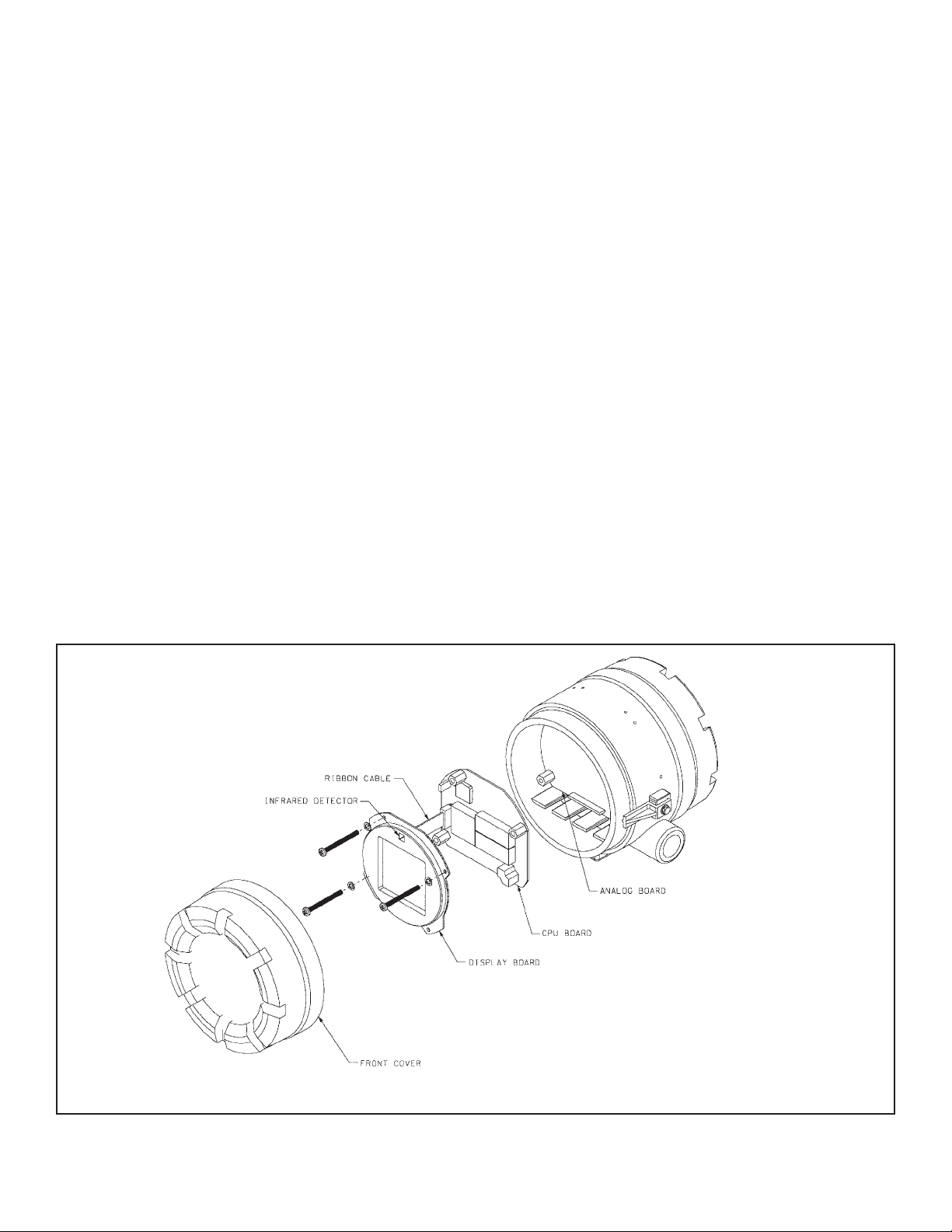
FIGURE 2-1. Model 3081 pH/ORP Transmitter - Exploded Drawing of Circuit Board Stack
2.2.4 Preamplifier Location
pH sensors produce a high impedance voltage signal that must be preamplified before use. The signal can be preamplified before it reaches the transmitter or it can be preamplified in the transmitter. To work properly, the transmitter must know
where preamplification occurs. Although ORP sensors produce a low impedance signal, the voltage from an ORP sensor
is amplified the same way as a pH signal.
If the sensor is wired to the transmitter through a junction box, the preamplifier is ALWAYS in either the junction box or the
sensor. Junction boxes can be attached to the sensor or installed some distance away. If the junction box is not attached
to the sensor, it is called a remote junction box. In most junction boxes used with the Model 3081 pH/ORP, a flat, black
plastic box attached to the same circuit board as the terminal strips houses the preamplifier. The preamplifier housing in
the 381+ sensor is crescent shaped.
If the sensor is wired directly to the transmitter, the preamplifier can be in the sensor or in the transmitter. If the sensor
cable has a GREEN wire, the preamplifier is in the sensor. If there is no green wire, the sensor cable will contain a coaxial cable. Acoaxial cable is an insulated wire surrounded by a braided metal shield. Depending on the sensor model, the
coaxial cable terminates in either a BNC connector or in a separate ORANGE wire and CLEAR shield.
2.2.5 Changing Switch and Jumper Positions
If the sensor and installation does not match the transmitter default settings in Section 2.2.1, change the settings to the
correct values.
1. Refer to Figure 2-1.
2. Loosen the cover lock nut until the tab disengages from the front cover. Unscrew the cover.
3. Remove the three bolts holding the circuit board stack.
4. Lift out the display board. Do not disconnect the ribbon cable between it and the CPU board. The CPU and analog
boards are joined by a pin and socket connector along the bottom edge of the boards. Carefully disengage the CPU
board from the analog board. The analog board will remain attached to the transmitter body.
Page 23
9
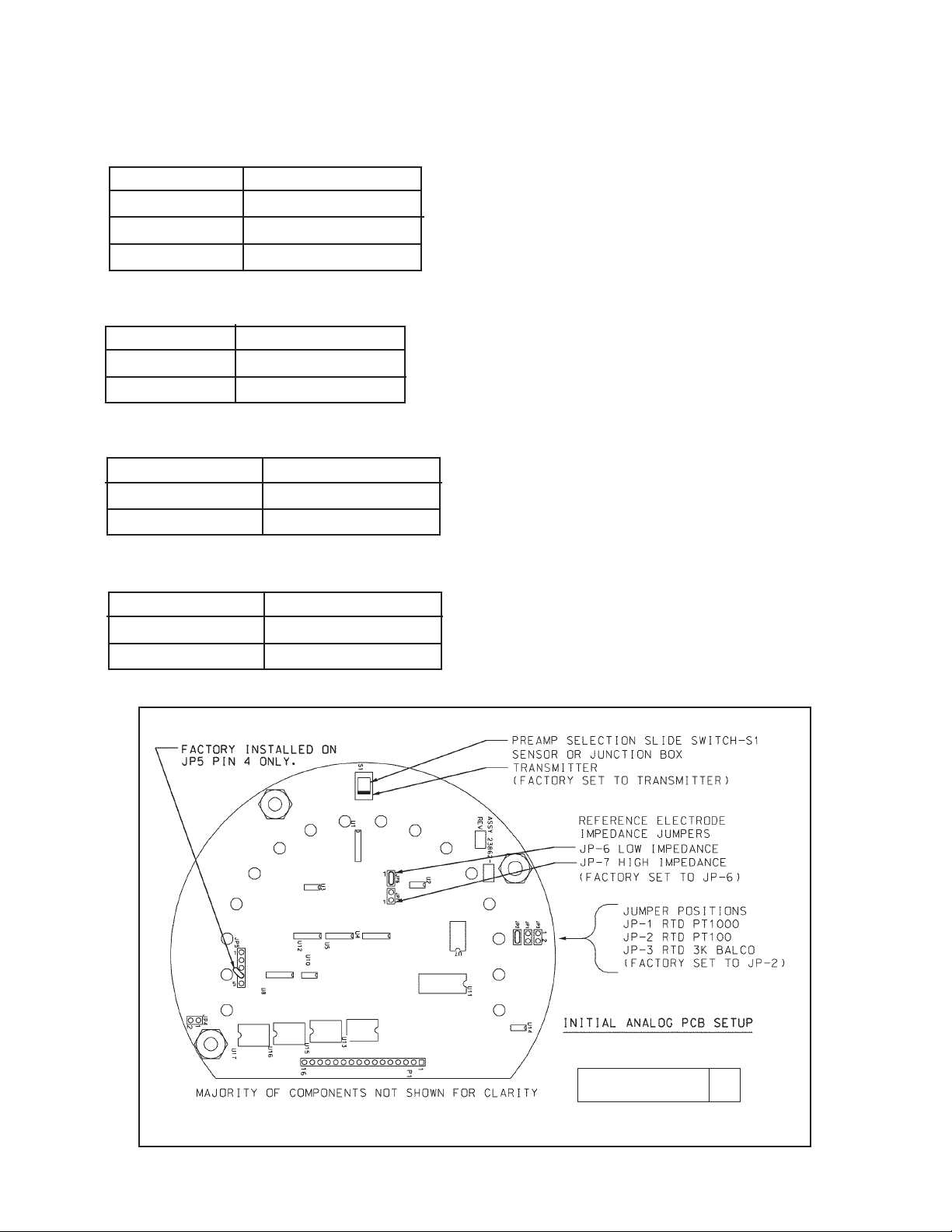
5. Set the jumpers and the slide switch on the analog board. Refer to Figure 2-2.
a. Temperature element jumper.
Jumper position Temperature element
JP-1 Pt 1000 RTD
JP-2 Pt 100 RTD
JP-3 3K Balco RTD
b. Reference impedance jumper.
Jumper position Reference impedance
JP-6 low
JP-7 high
c. Reference impedance jumper JP-5.
Jumper position Reference impedance
Pin 4 only low
Pin 3 and Pin 4 high
d. Preamplifier location selection switch.
Move slider toward Preamplifier location
edge of board sensor or junction box
center of board transmitter
MODEL 3081 pH/ORP SECTION 2.0
INSTALLATION
FIGURE 2-2. Model 3081 pH/ORP Transmitter Analog Board
DWG. NO. REV.
40308110 H
The transmitter must also be programmed to recognize the
RTD. If pH is being measured, see Section 8.5. If ORP is
being measured, see Section 10.5.
If sensor diagnostics are to be used with a high impedance
reference electrode, the high impedance must be identified
in the diagnostics setup program. See Section 8.4 for pH
measurements. See Section 10.4 for ORP measurements.
Leave jumper connected on Pin 4 only, unless a high
impedance reference is used. (NOTE: all standard sensors use low impedance references).
Page 24
10
MODEL 3081 pH/ORP SECTION 2.0
INSTALLATION
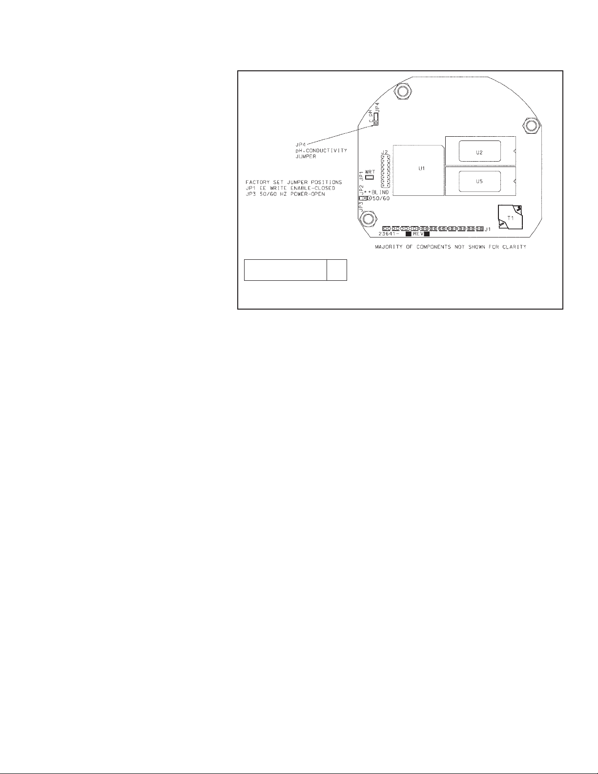
6. There are more jumpers on the CPU
board. Refer to Figure 2-3. These
jumpers are factory set and should NOT
need to be moved. This step is for troubleshooting purposes only.
Verify that jumpers JP-1, JP-3, and JP-4
on the CPU board are in the positions
shown in Figure 2-3. For installations
where 50 Hz ac power is present, closing
JP-3 may improve immunity of the transmitter to noise.
7. To reassemble the stack, place the display board on the CPU board. Be sure
the display board is properly oriented.
The small window (the infrared detector
for the remote controller) marks the top of
the board. Insert the three bolts through
the holes. Align the bolts with the standoffs on the analog board and position the
display and CPU boards on the analog
board. If the boards are properly aligned,
the bolts will drop in place. Press along
the bottom of the stack to seat the pin
and socket connector. Tighten the bolts.
8. Replace the end cap and lock nut.
2.3 ORIENTING THE DISPLAY BOARD
The display board can be rotated 90 degrees, clockwise or counterclockwise, from the original position. To reposition the
display:
1. Loosen the cover lock nut until the tab disengages from the circuit end cap. Unscrew the cap.
2. Remove the three bolts holding the circuit board stack.
3. Lift and rotate the display board 90 degrees, clockwise or counterclockwise, into the desired position.
4. Position the display board on the stand offs. Replace and tighten the bolts.
5. Replace the circuit end cap.
2.4 MECHANICAL INSTALLATION
2.4.1 General information
1. The transmitter tolerates harsh environments. For best results, install the transmitter in an area where temperature
extremes, vibrations, and electromagnetic and radio frequency interference are minimized or absent.
2. To prevent unintentional exposure of the transmitter circuitry to the plant environment, keep the security lock in place
over the circuit end cap. To remove the circuit end cap, loosen the lock nut until the tab disengages from the end cap,
then unscrew the cover.
3. The transmitter has two 3/4-inch conduit openings, one on each side of the housing. Run sensor cable through the left
side opening (as viewed from the wiring terminal end of the transmitter) and run power/current loop wiring through the
right side opening.
FIGURE 2-3. Model 3081 pH/ORP Transmitter CPU Board
DWG. NO. REV.
40008125 A
Page 25
11
MODEL 3081 pH/ORP SECTION 2.0
INSTALLATION
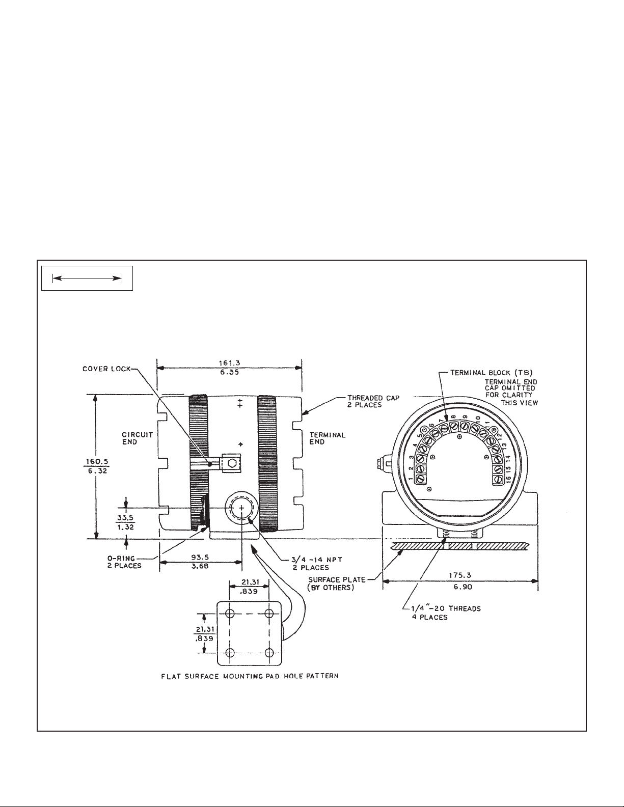
FIGURE 2-4. Mounting the Model 3081 pH/ORP Transmitter on a Flat Surface
MILLIMETER
INCH
4. Use weathertight cable glands to keep moisture out of the transmitter.
5. If conduit is used, plug and seal the connections at the transmitter housing to prevent moisture from getting inside the
transmitter.
NOTE
Moisture accumulating in the transmitter housing can affect the performance of the transmitter and may void the warranty.
6. If the transmitter is installed some dist ance from the sensor, a remote junction box with preamplifier in the junction box
or in the sensor may be necessary. Consult the sensor instruction manual for maximum cable lengths.
2.4.2 Mounting on a Flat Surface.
See Figure 2-4.
Page 26
12
MODEL 3081 pH/ORP SECTION 2.0
INSTALLATION
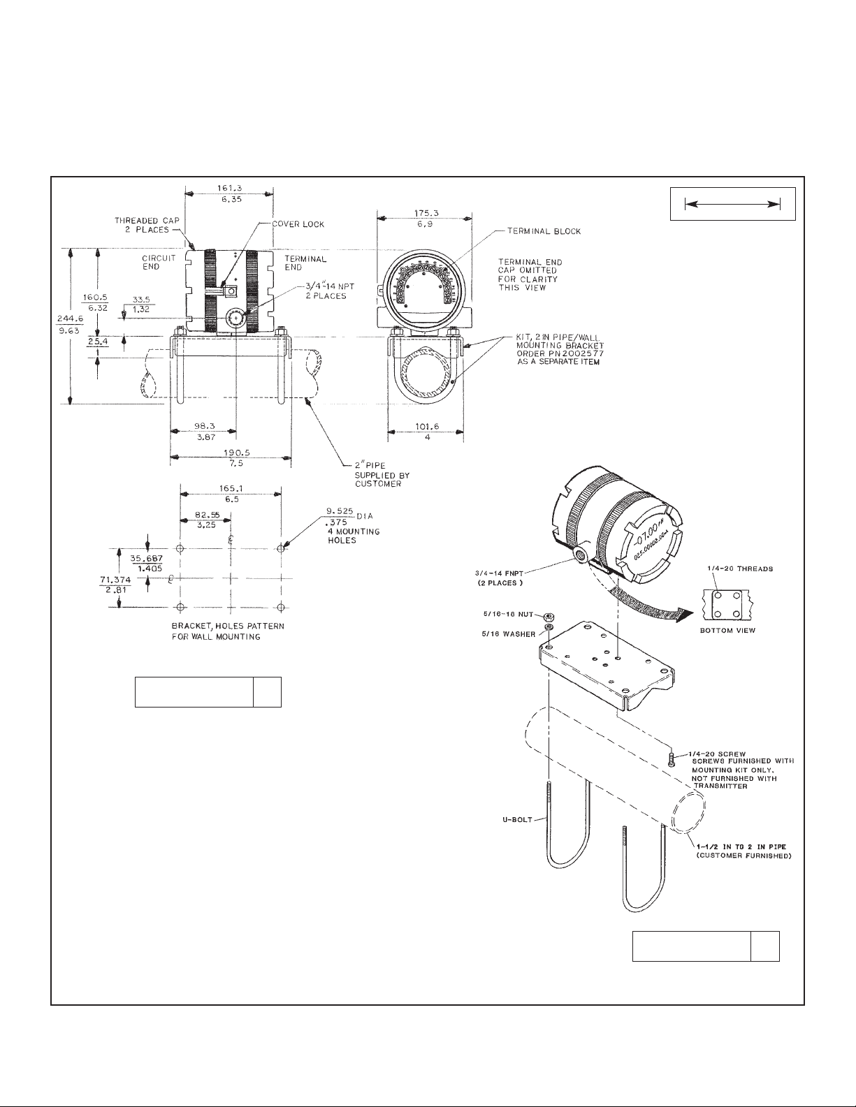
FIGURE 2-5. Using the Pipe Mounting Kit to Attach the Model 3081 pH/ORP Transmitter to a Pipe
MILLIMETER
INCH
2.4.3 Pipe Mounting.
See Figure 2-5. The pipe mounting kit (PN 2002577) accommodates 1-1/2 to 2 in. pipe.
DWG. NO. REV.
40308104 G
DWG. NO. REV.
40308103 C
Page 27
13
MODEL 3081 pH/ORP SECTION 2.0
INSTALLATION
2.5 POWER SUPPLY/CURRENT LOOP
2.5.1 Power Supply and Load Requirements.
Refer to Figure 2-6.
The minimum power supply voltage is 12.5 Vdc and
the maximum is 42.4 Vdc. The top line on the graph
gives the voltage required to maintain at least 12.5
Vdc at the transmitter terminals when the output signal is 22 mA. The lower line is the supply voltage
required to maintain a 30 Vdc terminal voltage when
the output signal is 22 mA.
The power supply must provide a surge current
during the first 80 milliseconds of start-up. For a
24 Vdc power supply and a 250 ohm load resistor
the surge current is 40 mA. For all other supply
voltage and resistance combinations the surge
current is not expected to exceed 70 mA.
For digital (HART or AMS) communications, the
load must be at least 250 ohms. To supply the 12.5
Vdc lift off voltage at the transmitter, the power supply voltage must be at least 18 Vdc.
For intrinsically safe operation the supply voltage should not exceed 42.4 Vdc.
FIGURE 2-6. Load/Power Supply Requirements
FIGURE 2-7. Power Supply/Current Loop Wiring
2.5.2 Power Supply-Current Loop
Wiring. Refer to Figure 2-7.
Run the power/signal wiring through
the opening nearest terminals 15 and
16. Use shielded cable and ground the
shield at the power supply. To ground
the transmitter, attach the shield to the
grounding screw on the inside of the
transmitter case. A third wire can also
be used to connect the transmitter
case to earth ground.
NOTE
For optimum EMI/RFI
immunity, the power supply/output cable should
be shielded and
enclosed in an earthgrounded metal conduit.
Do not run power supply/signal wiring
in the same conduit or cable tray with
AC power lines or with relay actuated
signal cables. Keep power supply/ signal wiring at least 6 ft (2 m) away from
heavy electrical equipment.
An additional 0-1 mA current loop is
available between TB-14 and TB-15. A
1 mA current in this loop signifies a
sensor fault. See Figure 4-3 for wiring
instructions. See Section 8.3 or 10.3
and Section 12.0 for more information
about sensor faults.
DWG. NO. REV.
40308122 B
Page 28
14
MODEL 3081 pH/ORP SECTION 3.0
WIRING
SECTION 3.0
WIRING
3.1 GENERAL INFORMATION
pH and ORP sensors manufactured by Rosemount Analytical can be wired to the Model 3081 pH/ORPtransmitter in three
ways:
1. directly to the transmitter,
2. to a sensor-mounted junction box and then to the transmitter,
3. to a remote junction box and then from the remote junction box to the transmitter.
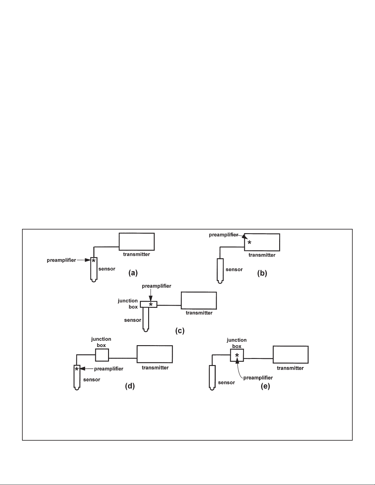
The pH (or ORP) signal can also be preamplified in one of four places.
1. in the sensor,
2. in a junction box mounted on the sensor,
3. in a remote junction box.
4. at the transmitter.
Figure 3-1 illustrates the various arrangements.
3.1 General Information
3.2 Wiring Diagrams
FIGURE 3-1. Wiring and Preamplifier Configurations for pH and ORP Sensors.
The asterisk identifies the location of the preamplifier. In (a) and (b) the sensor is wired directly to the transmitter. The signal is
amplified at the sensor (a) or at the transmitter (b). In (c) the sensor is wired through a sensor-mounted junction box to the transmitter. The preamplifier is in the sensor-mounted junction box. In (d) and (e) the sensor is wired through a remote junction box to
the transmitter. The preamplifier is located in the sensor (d) or the junction box (e).
Page 29

MODEL 3081 pH/ORP SECTION 3.0
WIRING
3.2 WIRING DIAGRAMS FOR pH and ORP SENSORS
Refer to Tables 3-1 through 3-12 to locate the appropriate wire function and wiring diagram. There is a separate table for
each model. The sensor models having the highest number appear first. If you do not know the model number of the
sensor, refer to the flow charts on pages 28 through 30. Only the model option numbers needed to select the cor-
rect wiring diagram are shown. Other numbers are not shown. For all other sensors, see sensor manual.
Table 3-1. Wiring Diagrams for Model 399 sensors
Sensor Junction Box Preamplifier RTD Wire Function Wiring Diagram
399-02 none in transmitter 3K Balco** Figure 3-2 Figure 3-4
399-02 remote in remote junction box 3K Balco** Figure 3-2 Figure 3-5
399-09* none in transmitter Pt 100 Figure 3-2 Figure 3-4
399-09* remote in remote junction box Pt 100 Figure 3-2 Figure 3-5
399-09-62 none in transmitter Pt 100 Figure 3-3 Figure 3-4
399-09-62 remote in remote junction box Pt 100 Figure 3-3 Figure 3-5
399-33 (ORP only) none in transmitter Pt 100 Figure 3-21 Figure 3-22
Table 3-2 Wiring Diagrams for Model 397 Sensors
Sensor Junction Box Preamplifier RTD Wire Function Wiring Diagram
397-50 none in transmitter 3K Balco** Figure 3-6 Figure 3-8
397-50 remote in remote junction box 3K Balco** Figure 3-6 Figure 3-9
397-54* none in transmitter Pt 100 Figure 3-6 Figure 3-8
397-54* remote in remote junction box Pt 100 Figure 3-6 Figure 3-9
397-54-62 none in transmitter Pt 100 Figure 3-7 Figure 3-8
397-54-62 remote in remote junction box Pt 100 Figure 3-7 Figure 3-9
Table 3-3 Wiring Diagrams for Model 396R Sensors
Sensor Junction Box Preamplifier RTD Wire Function Wiring Diagram
396R-50 remote in remote junction box 3K Balco** Figure 3-10 Figure 3-12
396R-50 none in transmitter 3K Balco** Figure 3-10 Figure 3-11
396R-50-60 sensor-mounted in sensor-mounted junction box 3K Balco** Figure 3-6 Figure 3-9
396R-54 none in transmitter Pt 100 Figure 3-10 Figure 3-11
396R-54 remote in remote junction box Pt 100 Figure 3-10 Figure 3-12
396R-54-60 sensor-mounted in sensor-mounted junction box Pt 100 Figure 3-7 Figure 3-9
396R-54-61 sensor-mounted in sensor-mounted junction box Pt 100 Figure 3-10 Figure 3-12
* Sensors have a BNC connector that the Model 3081 pH/ORP transmitter does not accept. Cut off the BNC and terminate
the coaxial cable as shown in Figure 3-23. Alternatively, use a BNC adapter (PN 9120531).
** Set the RTD jumper to the 3K position (see Section 2.2). Also, program the transmitter to recognize the 3K RTD (see
Section 8.5 for pH or 10.5 for ORP).
15
Page 30

16
MODEL 3081 pH/ORP SECTION 3.0
WIRING
Table 3-4 Wiring Diagrams for Model 396P Sensors
Sensor Junction Box Preamplifier RTD Wire Function Wiring Diagram
396P-01-55 none in sensor Pt 100 Figure 3-13 Figure 3-14
396P-01-55 remote in sensor Pt 100 Figure 3-13 Figure 3-14
396P-02-50 none in transmitter 3K Balco** Figure 3-10 Figure 3-11
396P-02-50 remote in remote junction box 3K Balco** Figure 3-10 Figure 3-12
396P-02-54 none in transmitter Pt 100 Figure 3-10 Figure 3-11
396P-02-54 remote in remote junction box Pt 100 Figure 3-10 Figure 3-12
396P-02-55 none in transmitter Pt 100 Figure 3-10 Figure 3-11
396P-02-55 remote in remote junction box Pt 100 Figure 3-10 Figure 3-12
Table 3-5 Wiring Diagrams for Model 396 Sensor
Sensor Junction Box Preamplifier RTD Wire Function Wiring Diagram
396-50* none in transmitter 3K Balco** Figure 3-6 Figure 3-8
396-50* remote in remote junction box 3K Balco** Figure 3-6 Figure 3-9
396-54* none in transmitter Pt 100 Figure 3-6 Figure 3-8
396-54* remote in remote junction box Pt 100 Figure 3-6 Figure 3-9
396-54-62 none in transmitter Pt 100 Figure 3-7 Figure 3-8
396-54-62 remote in remote junction box Pt 100 Figure 3-7 Figure 3-9
Table 3-6 Wiring Diagrams for Model 389 Sensors
Sensor Junction Box Preamplifier RTD Wire Function Wiring Diagram
389-02-50* none in transmitter 3K Balco** Figure 3-6 Figure 3-8
389-02-50* remote in remote junction box 3K Balco** Figure 3-6 Figure 3-9
389-02-54* none in transmitter Pt 100 Figure 3-6 Figure 3-8
389-02-54* remote in remote junction box Pt 100 Figure 3-6 Figure 3-9
389-02-54-62 none in transmitter Pt 100 Figure 3-7 Figure 3-8
389-02-54-62 remote in remote junction box Pt 100 Figure 3-7 Figure 3-9
* Sensors have a BNC connector that the Model 3081 pH/ORP transmitter does not accept. Cut off the BNC and terminate
the coaxial cable as shown in Figure 3-23. Alternatively, use a BNC adapter (PN 9120531).
** Set the RTD jumper to the 3K position (see Section 2.2). Also, program the transmitter to recognize the 3K RTD (see
Section 8.5 for pH or 10.5 for ORP).
Page 31

17
MODEL 3081 pH/ORP SECTION 3.0
WIRING
Table 3-7 Wiring Diagrams for Model 385+ Sensors
Sensor Junction Box Preamplifier RTD Wire Functions Wiring Diagram
385+ -02 sensor-mounted in sensor-mounted junction box Pt 100 Figure 3-15 Figure 3-16
385+ -03 none in sensor Pt 100 Figure 3-13 Figure 3-14
385+ -03 remote in sensor Pt 100 Figure 3-13 Figure 3-14
385+ -04 none in transmitter Pt 100 Figure 3-10 Figure 3-11
385+ -04 remote in remote junction box Pt 100 Figure 3-10 Figure 3-12
Table 3-8 Wiring Diagrams for Model 381+ Sensors
Sensor Junction Box Preamplifier RTD Wire Functions Wiring Diagram
381+ -40-55 none in sensor Pt 100 Figure 3-13 Figure 3-14
381+ -43-55 none in sensor Pt 100 Figure 3-13 Figure 3-14
381+ -40-55 remote in sensor Pt 100 Figure 3-13 Figure 3-14
381+ -43-55 remote in sensor Pt 100 Figure 3-13 Figure 3-14
381+ -41-52 none in transmitter Pt 100 Figure 3-10 Figure 3-11
381+ -41-52 remote in remote junction box Pt 100 Figure 3-10 Figure 3-12
Table 3-9 Wiring Diagrams for Model 381pHE and 381pH Sensors
Sensor Junction Box Preamplifier RTD Wire Functions Wiring Diagram
381pH-30-41-52* none in transmitter 3K Balco** Figure 3-2 Figure 3-4
381pH-30-41-52* remote in remote junction box 3K Balco** Figure 3-2 Figure 3-5
381pH-30-42-52 none in transmitter 3K Balco** Figure 3-3 Figure 3-4
381pH-30-42-52 remote in remote junction box 3K Balco** Figure 3-3 Figure 3-5
381pHE-31-41-52* none in transmitter Pt 100 Figure 3-2 Figure 3-4
381pHE-31-41-52* remote in remote junction box Pt 100 Figure 3-2 Figure 3-5
381pHE-31-42-52 none in transmitter Pt 100 Figure 3-3 Figure 3-4
381pHE-31-42-52 remote in remote junction box Pt 100 Figure 3-3 Figure 3-5
Table 3-10 Wiring Diagrams for Model 328A Sensor
Sensor Junction Box Preamplifier RTD Wire Functions Wiring Diagram
328A none in transmitter none Figure 3-17 Figure 3-18
Table 3-11 Wiring Diagrams for Model 320HP Sensor
Sensor Junction Box Preamplifier RTD Wiring Diagram
320HP-10-55 on mounting plate in transmitter Pt 100 Figure 3-19
320HP-10-58 on mounting plate in junction box attached to mounting plate Pt 100 Figure 3-20
* Sensors have a BNC connector that the Model 3081 pH/ORP transmitter does not accept. Cut off the BNC and terminate the coaxi-
al cable as shown in Figure 3-23. Alternatively, use a BNC adapter (PN 9120531).
** Set the RTD jumper to the 3K position (see Section 2.2). Also, program the transmitter to recognize the 3K RTD (see Section 8.5
for pH or 10.5 for ORP).
Page 32

18
MODEL 3081 pH/ORP SECTION 3.0
WIRING
REMOVE BNC AND TERMINATE COAXIAL CABLE BEFORE WIRING SENSOR TO
TRANSMITTER. SEE FIGURE 3-23. ALTERNATIVELY, USE A BNC ADAPTER (PN
9120531) OR ORDER MODEL OPTION -62 (SENSOR WITH BNC REMOVED AND TERMINATIONS COMPATIBLE WITH 3081 pH/ORP). IF USING A BNC ADAPTER, THE RED
WIRE IS MV OR pH IN AND THE BLACK WIRE IS REFERENCE IN. TO PREVENT
SHORT CIRCUITS TO THE TRANSMITTER HOUSING, INSULATE THE BNC WITH BY
WRAPPING IT WITH ELECTRICAL TAPE.
FIGURE 3-2. Wire functions for Models 399-02, 399-09, 381pH-30-41,
and 381pHE-31-41 before removing BNC and terminating cable.
IF USING ABNC ADAPTER, THE RED WIRE IS MV OR pH IN AND THE BLACK WIRE
IS REFERENCE IN. TO PREVENT SHORT CIRCUITS TO THE TRANSMITTER HOUSING, INSULATE THE BNC WITH BY WRAPPING IT WITH ELECTRICAL TAPE.
FIGURE 3-3. Wire functions for Models 399-02, 399-09,
381pH-30-41, and 381pHE-31-41 after removing BNC and
terminating cable. Wire functions for Models 399-09-10-62,
381pH-30-42 and 381pHE-31-42 as received.
NOTES:
1. PLACE PREAMPLIFIER SELECTION SWITCH S1 IN "TRANSMITTER" POSITION
(SEE SECTION 2.2).
2. IF SENSOR HAS 3K BALCO RTD, SET JUMPER (SECTION 2.2) AND PROGRAM
TRANSMITTER TO RECOGNIZE RTD (SECTION 8.5-pH OR 10.5-ORP)
3. JUMPERS SUPPLIED BY CUSTOMER.
FIGURE 3-4. Wiring diagram for Models 399-02, 399-09,
381pHE-30-41, and 381pHE-31-41 after removing BNC
and terminating cable. Wiring Diagram for Models
399-09-62, 381pHE-30-42, and 381pHE-31-42 as
received. Wiring directly to the transmitter.
NOTES:
1. PLACE PREAMPLIFIER SELECTION SWITCH S1 IN
"SENSOR/JUNCTION BOX" POSITION (SEE SECTION 2.2).
2. IF SENSOR HAS 3K BALCO RTD, SET JUMPER
(SECTION 2.2) AND PROGRAM TRANSMITTER TO
RECOGNIZE RTD (SECTION 8.5-pH OR 10.5-ORP)
3. SEE FIGURE 3-24 FOR TERMINATION OF RAW
INTERCONNECTING CABLE (PN 9200273).
4. JUMPERS SUPPLIED BY CUSTOMER.
FIGURE 3-5. Wiring diagram for Models 399-02,
399-09, 381pH-30-41, and 381pHE-31-41 after
removing BNC and terminating cable. Wiring
Diagram for 399-09-62, 381pH-30-42, and
381pH-31-42 as received. Wiring through a
remote junction box to the transmitter.
Page 33

19
MODEL 3081 pH/ORP SECTION 3.0
WIRING
REMOVE BNC AND TERMINATE COAXIAL CABLE BEFORE WIRING SENSOR TO
TRANSMITTER. SEE FIGURE 3-23. ALTERNATIVELY, USE A BNC ADAPTER (PN
9120531) OR ORDER MODEL OPTION -62 (SENSOR WITH BNC REMOVED AND
TERMINATIONS COMPATIBLE WITH 3081 pH/ORP). IF USING A BNC ADAPTER,
THE RED WIRE IS MV OR pH IN AND THE BLACK WIRE IS REFERENCE IN. TO
PREVENT SHORT CIRCUITS TO THE TRANSMITTER HOUSING, INSULATE THE
BNC WITH BY WRAPPING IT WITH ELECTRICAL TAPE.
FIGURE 3-6. Wire functions for Models 397-50, 397-54, 396-50,
396-54, 396R-50-60, 396R-54-60, 389-02-50, and 389-02-54
before removing BNC and terminating cable.
IF USING ABNC ADAPTER, THE RED WIRE IS MV OR pH IN AND THE BLACK WIRE
IS REFERENCE IN. TO PREVENT SHORT CIRCUITS TO THE TRANSMITTER
HOUSING, INSULATE THE BNC WITH BY WRAPPING IT WITH ELECTRICAL TAPE.
FIGURE 3-7. Wire functions for Models 397-50, 397-54, 396-50,
396-54, 396R-50-60, 396R-54-60, 389-02-50, and 389-02-54 after
removing BNC and terminating cable. Wire functions for
Models 397-54-62, 396-54-62, and 389-02-54-62 as received.
NOTES:
1. PLACE PREAMPLIFIER SELECTION SWITCH S1 IN "TRANSMITTER" POSITION
(SEE SECTION 2.2).
2. IF SENSOR HAS 3K BALCO RTD, SET JUMPER (SECTION 2.2) AND PROGRAM
TRANSMITTER TO RECOGNIZE RTD (SECTION 8.5-pH OR 10.5-ORP)
3. JUMPERS SUPPLIED BY CUSTOMER.
FIGURE 3-8. Wiring diagram for Models 397-50, 397-54, 396-50,
396-54, 389-02-50, and 389-02-54 after removing BNC and termi-
nating cable. Wiring diagram for Models 397-54-62, 396-54-62, and
389-02-54-62 as received. Wiring directly to the transmitter.
NOTES:
1. PLACE PREAMPLIFIER SELECTION SWITCH S1 IN "SENSOR/JUNCTION BOX" POSITION (SEE SECTION 2.2).
2. IF SENSOR HAS 3K BALCO RTD, SET JUMPER (SECTION
2.2) AND PROGRAM TRANSMITTER TO RECOGNIZE RTD
(SECTION 8.5-pH OR 10.5-ORP)
3. SEE FIGURE 3-24 FOR TERMINATION OF RAW
INTERCONNECTING CABLE (PN 9200273).
4. JUMPERS SUPPLIED BY CUSTOMER.
FIGURE 3-9. Wiring diagram for Models 397-50,
397-54, 396-50, 396R-50-60, 396R-54-60, 396-54,
389-02-50, and 389-02-54 after removing BNC
and terminating cable. Wiring diagram for
Models 397-54-62, 396-54-62, and 389-02-54-62
as received. Wiring through a remote junction
box to the transmitter.
3
4
Page 34

20
MODEL 3081 pH/ORP SECTION 3.0
WIRING
FIGURE 3-10. Wire functions for Models 396R-50,
396R-54, 396R-54-61, 396P-02-50, 396P-02-54,
396P-02-55, 385+ -04, and 385+ -41-52.
NOTES:
1. PLACE PREAMPLIFIER SELECTION SWITCH S1 IN "TRANSMITTER" POSITION (SEE SECTION 2.2).
2. IF SENSOR HAS 3K BALCO RTD, SET JUMPER (SECTION 2.2)
AND PROGRAM TRANSMITTER TO RECOGNIZE RTD (SECTION 8.5-pH OR 10.5-ORP)
3. JUMPER SUPPLIED BY CUSTOMER.
4. DO NOT CONNECT BLUE WIRE. INSULATE STRIPPED END
OF WIRE TO A VOID ACCIDENTAL CONNECTIONS.
FIGURE 3-11. Wiring diagram for Models 396R-50,
396R-54, 396R-54-61, 396P-02-50, 396P-02-54,
396P-02-55, 385+ -04, and 385+ -41-52.
Wiring directly to the transmitter.
NOTES:
1. PLACE PREAMPLIFIER SELECTION SWITCH S1 IN "SENSOR/JUNCTION BOX" POSITION (SEE SECTION 2.2).
2. IF SENSOR HAS 3K BALCO RTD, SET JUMPER (SECTION 2.2)
AND PROGRAM TRANSMITTER TO RECOGNIZE RTD (SECTION 8.5 [pH] OR 10.5 [ORP])
3. SEE FIGURE 3-24 FOR TERMINATION OF RAW INTERCONNECTING CABLE (PN 9200273).
4. JUMPER SUPPLIED BY CUSTOMER.
5. DO NOT CONNECT BLUE WIRE. INSULATE STRIPPED END
OF WIRE TO A VOID ACCIDENTAL CONNECTIONS.
FIGURE 3-12. Wiring diagram for Models 396R-50,
396R-54, 396R-54-61, 396P-02-50, 396P-02-54,
396P-02-55, 385+ -04, and 385+ -41-52.
Wiring through a sensor-mounted junction
box to the transmitter.
4
5
3
3
Page 35

21
MODEL 3081 pH/ORP SECTION 3.0
WIRING
FIGURE 3-13. Wire functions for Models 396P-01-55, 385+ -03,
381+ -40-55, and 381+ -43-55.
NOTES:
1. PLACE PREAMPLIFIER SELECTION SWITCH S1 IN
"SENSOR/JUNCTION BOX" POSITION (SEE SECTION 2.2).
2. TO EXTEND CABLE LENGTH, USE JUNCTION BOX PN 2355000 WITH EXTENSION CABLE PN 23646-01 (FINISHED) OR PN
9200273 (UNFINISHED). WIRE THROUGH TERMINALS POINT
TO POINT. SEE FIGURE 3-24 FOR TERMINATION OF RAW
CABLE PN 9200273.
FIGURE 3-14. Wiring diagram for Models 396P-01-55,
385+ -03, 381+ -40-55, and 381+ -43-55.
Page 36

22
MODEL 3081 pH/ORP SECTION 3.0
WIRING
FIGURE 3-15. Wire functions for Model 385+ -02.
NOTES:
1. PLACE PREAMPLIFIER SELECTION SWITCH S1 IN "SENSOR/JUNCTION BOX" POSITION (SEE
SECTION 2.2).
2. SEE FIGURE 3-24 FOR TERMINATION OF RAW INTERCONNECTING CABLE (PN 9200273).
3. JUMPER SUPPLIED BY CUSTOMER.
4. DO NOT CONNECT BLUE WIRE. INSULATE STRIPPED END OF WIRE TO AVOID ACCIDENTAL
CONNECTIONS.
FIGURE 3-16. Wiring diagram for Model 385+ -02.
Page 37

23
MODEL 3081 pH/ORP SECTION 3.0
WIRING
NOTE: MODEL 328A-08 HAS UNDRESSED COAXIAL CABLE. SEE SENSOR INSTRUCTION
SHEET FOR CABLE PREPARATION PROCEDURE.
FIGURE 3-17. Wire functions for Model 328A-07.
NOTES:
1. PLACE PREAMPLIFIER SELECTION SWITCH S1 IN "TRANSMITTER" POSITION (SEE SECTION 2.2).
2. JUMPERS SUPPLIED BY CUSTOMER.
3. MODEL 328A-08 HAS UNDRESSED COAXIAL CABLE. CABLE
MUST BE TERMINATED BEFORE WIRING SENSOR TO TRANSMITTER. CENTRAL CONDUCTOR IS pH SIGNAL (TB-10) AND
SHIELD IS REFERENCE SIGNAL (TB-7). SEE SENSOR
INSTRUCTION SHEET FOR DETAILS.
4. AUTOMATIC TEMPERATURE COMPENSATION MUST BE
TURNED OFF. SEE SECTION 8.5.
FIGURE 3-18. Wiring diagram for Model 328A.
Page 38

24
MODEL 3081 pH/ORP SECTION 3.0
WIRING
NOTES:
1. PLACE PREAMPLIFIER SELECTION SWITCH S1 IN "TRANSMITTER" POSITION (SEE SECTION 2.2).
2. TERMINALS IN JUNCTION BOX ARE NOTNUMBERED.
COUNT POSITION FROM LEFT TO RIGHT AS SHOWN IN
DRAWING.
3. JUMPERS SUPPLIED BY CUSTOMER.
4. CUSTOMER MUST INSTALLAND WIRE pH ELECTRODE
AND TEMPERATURE SENSOR.
5. SEE SENSOR MANUAL FOR PREPARATION OF EXTENSION
CABLE (PN 661-646983).
6. DISCONNECT WHITE GUARD WIRE FROM TB-7 AND INSULATE STRIPPED END.
FIGURE 3-19. Wiring diagram for Model 320HP-10-55.
NOTES:
1. PLACE PREAMPLIFIER SELECTION SWITCH S1 IN
"SENSOR/JUNCTION BOX" POSITION (SEE SECTION 2.2).
2. JUMPERS SUPPLIED BY CUSTOMER.
3. CUSTOMER MUST INSTALLAND WIRE pH ELECTRODE AND TEMPERATURE SENSOR.
4. SEE SENSOR MANUAL FOR PREPARATION OF EXTENSION
CABLE (PN 661-646983).
FIGURE 3-20 Wiring diagram for Model 320HP-10-58.
Page 39

25
MODEL 3081 pH/ORP SECTION 3.0
WIRING
FIGURE 3-21. Wire Functions for Model 399-33
FIGURE 3-22. Wiring Diagram for Model 399-33
Page 40

26
MODEL 3081 pH/ORP SECTION 3.0
WIRING
FIGURE 3-23. Procedure for Removing BNC Connector and Preparing Coaxial Cable
Page 41

27
MODEL 3081 pH/ORP SECTION 3.0
WIRING
FIGURE 3-24. Preparation of Raw Connecting Cable (PN 9200273).
Page 42

28
MODEL 3081 pH/ORP SECTION 3.0
WIRING
SENSOR FLOW CHART (continued on page 29)
Page 43

29
MODEL 3081 pH/ORP SECTION 3.0
WIRING
SENSOR FLOW CHART (continued on page 30)
Page 44

30
MODEL 3081 pH/ORP SECTION 3.0
WIRING
SENSOR FLOW CHART
Page 45

31
4.1 INTRINSICALLY SAFE INSTALLATIONS
The installation wiring, operating parameters, or agency tags for intrinsically safe operation are given in Figures
4-1, 4-2, and 4-3.
4.2 EXPLOSION PROOF INSTALLATIONS
The installation wiring and operating parameters for explosion proof operation are given in Figure 4-4.
MODEL 3081 pH/ORP SECTION 4.0
INTRINSICALLY SAFE & EXPLOSION PROOF
SECTION 4.0
INTRINSICALLY SAFE & EXPLOSION PROOF
4.1 Intrinsically Safe Installations
4.2 Explosion Proof Installations
FIGURE 4-1. Intrinsically Safe BASEEFA Model 3081 Label
Page 46

32
FIGURE 4-2. FMRC Installation for Model 3081 pH/ORP Transmitter
Page 47

33
Page 48

FIGURE 4-3. CSA Installation for Model 3081 pH/ORP Transmitter
34
Page 49

35
Page 50

FIGURE 4-4. Explosion-Proof Installation for Model 3081 pH/ORP Transmitter
36
Page 51

37
MODEL 3081 pH/ORP SECTION 5.0
OPERATION WITH REMOTE CONTROLLER
SECTION 5.0
OPERATION WITH REMOTE CONTROLLER
CALIBRATE PROGRAM DIAGNOSE
CALIbrAtE
EXIT NEXT ENTER
7.00
pH
MV
F
A
U
L
T
H
O
L
D
♥
Appears when transmitter
is in hold (see Section 8.3.2)
Appears when a disabling
condition has occurred
(see Section 8.3.2)
Appears during HART and AMS
operations
Active menu: CALIBRATE,
PROGRAM, or DIAGNOSE
Sub-menus, prompts, and
diagnostic messages appear
here
pH or ORP (ORP in mV)
Units of display
Available commands for submenu, prompt, or diagnostic
5.1 Displays
5.2 Infrared Remote Controller (IRC) - Key Functions
5.3 Menu Tree - pH
5.4 Diagnostic Messages - pH
5.5 Menu Tree - ORP
5.6 Diagnostic Messages - ORP
5.7 Security
FIGURE 5-2. Program Display Screen
The program display screen appears when calibrating, programming, or reading diagnostic messages.
FIGURE 5-1. Process Display Screen
The process display screen appears during normal operation.
pH or ORP (ORP in mV)
Temperature in °C or °F
Transmitter output signal in
mA or % of full scale
5.1 DISPLAYS
Figure 5-1 shows the process display screen, and Figure 5-2 shows the program display screen.
Page 52

38
MODEL 3081 pH/ORP SECTION 5.0
OPERATION WITH REMOTE CONTROLLER
5.2 INFRARED REMOTE CONTROLLER (IRC) - KEY FUNCTIONS
The infrared remote controller is used to calibrate and program the transmitter and to read diagnostic messages.
See Figure 5-3 for a description of the function of the keys.
Hold the IRC within 6 feet of the transmitter, and not more than 15 degrees from the center of the display window.
FIGURE 5-3. Infrared Remote Controller.
RESET - Press to end the current oper-
ation and return to the process display.
Changes will NOT be saved. RESET
does not return the transmitter to factory
default settings.
CAL - Press to access the calibrate
menu.*
PROG - Press to access the program
menu.*
DIAG - Press to view diagnostic messages.*
HOLD - Press to access the prompt that
turns on or off the Hold function.
Editing Keys - Use the editing keys to
change the value of a flashing display.
The left and right arrow keys move the
cursor one digit at a time across a number. The up and down arrow keys
increase or decrease the value of the
selected digit. The up and down arrow
keys also scroll the display through the
items in a list.
* Pressing CAL, PROG, or DIAG causes
the program screen to appear with the
selected menu (CALIBRATE, PROGRAM,
OR DIAGNOSE) showing. See Figure 5-2.
The first sub-menu (or the first diagnostic
message) also appears. Figure 5-4 shows
the complete menu tree.
ENTER - Press to advance from a submenu to the first prompt under the submenu. Pressing ENTER also stores the
selected item or value in memory and
advances to the next prompt.
NEXT - Press to advance to the next
sub-menu.
EXIT - Press to end the current operation. The transmitter returns to the first
prompt in the present sub-menu.
Changes will NOT be saved.
Page 53

39
MODEL 3081 pH/ORP SECTION 5.0
OPERATION WITH REMOTE CONTROLLER
PROGRAM
CALIBRATE
OutPut
GIMP 1000 V Er 81PH.21
tEMP 25 C
InPut 58.9 ShoW FLt
nonE
rIMP 10
dIAGnOStIC tEMP
bUFFErdISPLAY ISOPOtntAL
SIM OUtPUt
CALIbrAtE
Std
tEMP AdJ
tEMP 25.0
4 MA 00.00
20MA 14.00
HoLd 21.00
FAULt 22.00
dPn 0.00
tAUtO On
tMAn 25.0
tC 100-3
tYPE PH
tEMP C
OUtPUt Cur
COdE 000
bAUtO On
bUFFEr Std
tIME 10
PH 00.02
tCOEF 00.00
ISO 07.00
Snr 07.00
tESt 12.00
rOFFSt 060
dIAG OFF
IMPtC ON
GWH 1000
GFH 1500
GWL 020
GFL 010
CAL 000
rEF LO
rFH 140
rWH 040
rWL 000
rFL 000
CAL bF1
bF 1
bF1 4.01
CAL bF2
bF 2
bF2 10.01
DIAGNOSE
Std 7.00
SLOPE 59.01
MENU
Sub-menu
PROMPT
Diag Message
FIGURE 5-4. Menu Tree for pH
5.3 MENU TREE - pH
The Model 3081 pH transmitter has three menus: CALIBRATE, PROGRAM, and DIAGNOSE. Under the Calibrate and
Program menus are several sub-menus. For example, under CALIBRATE, the sub-menus are CALIbrAtE, Std (stan-
dard), and tEMP AdJ (temperature adjust). Under each sub-menu are prompts. For example, under St d, the prompts
are Std xx.xx and slope xx.xx. The DIAGNOSE menu lets the user view diagnostic messages. Figure 5-4 shows the
complete menu tree.
5.4 DIAGNOSTIC MESSAGES - pH
Whenever a warning or fault limit has been exceeded, the transmitter displays diagnostic messages to aid in troubleshooting. Diagnostic messages appear in the same area as the temperature/output readings in the process display
screen (see Figure 5-1). The display alternates between the regular display and the diagnostic message. Figure 5-4
shows the diagnostic fault messages for pH.
If more than one warning or fault message has been generated, the messages appear alternately.
See Section 12.0, Troubleshooting, for the meanings of the fault and warning messages.
Page 54

40
5.5 MENU TREE - ORP
The Model 3081 ORP transmitter has three menus: CALIBRATE, PROGRAM, and DIAGNOSE. Under the Calibrate and
Program menus are several sub-menus. For example, under CALIBRATE, the sub-menus are Std (standard) and tEMP
AdJ (temperature adjust). Under each sub-menu are prompts. For example, the Std sub-menu contains the single
prompt Std. Other sub-menus may contain more than one prompt. Figure 5-5 shows the complete menu tree.
5.6 DIAGNOSTIC MESSAGES - ORP
Whenever a warning or fault limit has been exceeded, the transmitter displays diagnostic messages to aid in troubleshooting. Diagnostic messages appear in the same area as the temperature/output readings in the process display
(Figure 5-1). The display alternates between the regular display and the diagnostic message. Figure 5-5 shows the
diagnostic fault messages for ORP.
If more than one warning or fault message has been generated, the messages appear alternately.
See Section 12.0, Troubleshooting, for the meanings of the fault and warning messages.
MODEL 3081 pH/ORP SECTION 5.0
OPERATION WITH REMOTE CONTROLLER
MENU
Sub-menu
PROMPT
Diag Message
FIGURE 5-5. Menu Tree for ORP
PROGRAMCALIBRATE
OutPut
rIMP 10
VEr 81PH.01
ShoW FLt
nonE
dIAGnOStIC tEMP
dISPLAY
SIM OUtPUt
Std
tEMP ADj
tEMP
4 MA -1400
20MA 1400
HoLd 21.00
FAULt 22.00
dPn 0.00
tC 100-3
tYPE ORP
tEMP C
OUtPUt CUr
COdE 000
tESt 12.00
rOFFSt 060
dIAG OFF
IMPtC OFF
rEF LO
rFH 140
rWH 040
rWL 000
rFL 000
Std 1000
DIAGNOSE
1400
mV
Page 55

41
5.7 SECURITY
5.7.1 General. Use the programmable security code to protect program and calibration
settings from accidentally being changed. The transmitter is shipped with the security feature disabled. To program a security code, refer to Section 8.6, Display Units.
5.7.2 Entering the Security Code.
1. If calibration and program settings are protected with a security code, pressing PROG
or CAL on the infrared remote controller causes the Id screen to appear.
2. Use the editing keys to enter the security code. Press ENTER .
3. If the security code is correct, the first sub-menu appears. If the security code is incorrect, the process display reappears.
5.7.3 Retrieving a Lost Security Code.
1. If the security code has been forgotten, enter 555 at the Id prompt and press ENTER .
The transmitter will display the present code.
2. Press EXIT to return to the process display.
3. Press PROG or CAL. The Id screen appears.
4. Use the editing keys to enter the security code just shown; then press ENTER .
5. The first sub-menu under the selected menu will appear.
MODEL 3081 pH/ORP SECTION 5.0
OPERATION WITH REMOTE CONTROLLER
PROGRAM
I d
EXIT ENTER
000
Page 56

42
6.1 Note on Model 275 HART Communicator
The Model 275 HART Communicator is a product of Rosemount Measurement. This section contains selected
information on using the Model 275 with the Rosemount Analytical Model 3081 pH/ORPTransmitter. For complete
information on the Model 275 Communicator, see the Model 275 instruction manual. For technical support on the
Model 275 Communicator, call Rosemount Measurement at (800) 999-9307, within the United States. Support is
available worldwide on the internet at http://rosemount.com.
6.2 Connecting the HART Communicator
Figure 6-1 shows how the Model 275 HART Communicator connects to the output lines from the Model 3081
pH/ORP Transmitter.
MODEL 3081 pH/ORP SECTION 6.0
OPERATION WITH MODEL275
SECTION 6.0
OPERATION WITH MODEL 275
6.1 Note on Model 275 HART Communicator
6.2 Connecting the HART Communicator
6.3 Operation
FIGURE 6-1. Connecting the HART Communicator
4-20 mA + Digital
250
ohm
Control System
Computer
Model 3081 pH
Smart
Transmitter
Bridge
Hand Held
Communicator
(“Configurator”)
CAUTION
For intrinsically safe CSA and FM
wiring connections, see the Model
275 instruction manual.
Page 57

43
MODEL 3081 pH/ORP SECTION 6.0
OPERATION WITH MODEL275
6.3 Operation
6.3.1 Off-line and On-line Operation
The Model 275 Communicator features off-line and on-line communications. On-line means the communicator is
connected to the transmitter in the usual fashion. While the communicator is on line, the operator can view measurement data, change program settings, and read diagnostic messages. Off-line means the communicator is not
connected to the transmitter. When the communicator is off line, the operator can still program settings into the
communicator. Later, after the communicator has been connected to a transmitter, the operator can transfer the
programmed settings to the transmitter. Off-line operation permits settings common to several transmitters to be
easily stored in all of them.
6.3.2 Menu Tree
Figure 6-2 shows the menu tree for the Model 3081 pH transmitter. Figure 6-3 shows the menu tree for the Model
3081 ORP transmitter.
6.3.3 Fast Key Sequences.
Fast key sequences are a series of key presses that begin at the on-line menu and lead directly to a given operation (for example, standardize). Some useful sequences are the following:
Key Presses
1. Calibrate with buffers 2311
2. Standardize 2321
3. Adjust current output to 2 4
match displayed value
4. Place transmitter in hold 2 5
5. Assign pH or ORP value 3 2 2
to 20 mA output
6. Assign pH or ORP value 3 2 1
to 4 mA output
7. View pH value 1 1 1
8. View analog output 1 2
9. View transmitter status 1 3
Page 58

44
MODEL 3081 pH/ORP SECTION 6.0
OPERATION WITH MODEL275
FIGURE 6-2a. pH Menu Tree (HART)
(Figure 6-2 is continued on page 41)
Page 59

45
MODEL 3081 pH/ORP SECTION 6.0
OPERATION WITH MODEL275
FIGURE 6-2b. pH Menu Tree (HART)
Page 60

46
MODEL 3081 pH/ORP SECTION 6.0
OPERATION WITH MODEL275
FIGURE 6-3a. ORP Menu Tree (HART)
(Figure 6-3 is continued on page 43)
Page 61

47
MODEL 3081 pH/ORP SECTION 6.0
OPERATION WITH MODEL275
FIGURE 6-3b. ORP Menu Tree (HART)
Page 62

48
MODEL 3081 pH/ORP SECTION 7.0
CALIBRATION OF pH MEASUREMENTS
SECTION 7.0
CALIBRATION OF pH MEASUREMENTS
7.1 General
7.2 Entering and Leaving the Calibrate Menu
7.3 Using the Hold Function
7.4 Temperature Calibration
7.5 Auto Calibration
7.6 Manual Calibration
7.7 Making the Transmitter Reading Match a
Second pH Meter (Standardization)
7.1 GENERAL
The Calibrate menu allows the user to calibrate the pH and temperature response of the sensor.
The transmitter does a two-point pH calibration. Both manual and auto calibration are available. In auto calibration the
transmitter automatically stores temperature-corrected calibration data once readings have met programmed stability limits. In manual calibration the user enters buffer values and judges when readings are stable. The transmitter reading can
also be made to match the reading of a second pH meter.
Temperature calibration is a one-point standardization against a reference thermometer.
Prompts guide the user through the calibration procedures.
7.2. ENTERING AND LEAVING THE CALIBRATE MENU
Press CAL on the infrared remote controller (IRC) to enter the Calibrate menu. To store new settings in memory, press
ENTER . To leave the Calibrate menu without storing new values, press EXIT . Pressing EXIT with a prompt showing
returns the display to the first prompt in the sub-menu. Pressing EXIT a second time returns the transmitter to the process
display.
If program settings are protected with a security code, pressing PROG or CAL will cause the Id screen to appear. Key
in the security code and press ENTER . The first sub-menu will appear. For more information, see Section 5.7, Security.
A transmitter adjacent to the one being calibrated may pick up signals from the IRC. To avoid accidentally changing settings, use a different security code for each nearby transmitter. See Section 5.7, Security, and Section 8.6, Display Units,
for details.
7.3 USING THE HOLD FUNCTION
During calibration, the sensor may be exposed to solutions having pH outside the normal range of the
process. To prevent false alarms and possible undesired operation of chemical dosing pumps, place the
transmitter in hold during calibration. Activating hold keep s the transmitter output at the last value or sends
the output to a previously determined value. See Section 8.3, Output Ranging, for details.
After calibration, reinstall the sensor in the process stream. Wait until readings have stabilized before
deactivating Hold.
To activate or deactivate Hold, do the following:
1. Press HOLD on the IRC.
2. The HoLd prompt appears in the display. Press Ï or Ðto toggle the Hold function between On and OFF.
3. Press ENTER to save.
Page 63

49
CALIBRATE
tEMP AAdJ
EXIT NEXT ENTER
CALIBRATE
tEMP
EXIT ENTER
025.0
MODEL 3081 pH/ORP SECTION 7.0
CALIBRATION OF pH MEASUREMENTS
7.4 TEMPERATURE CALIBRATION
7.4.1 Purpose
1. As discussed in Section 13.6, Glass Electrode Slope, measuring temperature is an important part of measuring pH. The accuracy of a new sensor
and transmitter loop is about ±1°C, which is adequate for most applications.
A new sensor seldom requires temperature calibration.
2. Calibrate the sensor/transmitter loop if . . .
a. ±1°C accuracy is NOT acceptable, or
b. the temperature measurement is suspected of being in error.
NOTE
A transmitter adjacent to the one being calibrated may pick up
signals from the IRC. To avoid accidentally changing settings,
use a different security code for each nearby transmitter. See
Section 5.7, Security.
7.4.2 Procedure
1. Place the pH sensor and a calibrated reference thermometer in an insulated
container of water at ambient temperature. Be sure the temperature element in the sensor is completely submerged by keeping the sensor tip at
least three inches below the water level. Do not let the weight of the sensor
rest on the glass bulb. Stir continuously. Allow at least 20 minutes for the
standard thermometer, sensor, and water to reach constant temperature.
2. Enter the CALIBRATE menu by pressing CAL on the IRC. The CALIbrAtE
sub-menu appears (pictured above left).
3. At the CALIbrAtE sub-menu, press NEXT twice. The tEMP AdJ sub-menu
appears.
4. Press ENTER to display the temperature editing prompt.
5. Compare the temperature displayed by the transmitter with the temperature
measured with the reference thermometer. If the readings are different, use
the editing keys to change the flashing display to the value determined with
the reference thermometer. The reading cannot be changed by more than
15°C.
6. Press ENTER . The value will be saved, and the display will return to the
tEMP AdJ sub-menu.
7. To leave the CALIBRATE menu, press EXIT .
8. Check linearity by measuring the temperature of water 10 to 15°C cooler
and 10 to 15°C warmer than the water used for calibration. Because of the
time required for the temperature element in the sensor to reach constant
temperature, a well-insulated container or, better, a constant temperature
bath is required for this step.
Page 64

50
7.5 AUTO CALIBRATION
7.5.1 Purpose
1. New sensors must be calibrated before use. Regular recalibration is also necessary.
2. The use of auto calibration instead of manual calibration is strongly recommended. Auto calibration avoids common pitfalls and reduces errors.
3. For more information about calibration in pH measurements and the use of buffers, refer to
Section 13.7, Buffers and Calibration.
7.5.2 What Happens During Auto Calibration?
1. The transmitter displays prompts that guide the user through a two-point buffer calibration.
2. The transmitter recognizes the buffers and uses the temperature-corrected pH value in the calibration. The transmitter also measures noise and drift and does not accept calibration data until
readings are stable. Stability limits are user-programmable. See Section 9.7, Buffer Calibration
Parameters.
7.5.3 Use of Calibration Standards (buffers)
1. A pH measurement is only as good as the calibration, and the calibration is only as good as the
buffers used. A careful buffer calibration is the first step in making an accurate pH measurement.
2. Calibrate with buffers having pH values that bracket the pH of the process. For example, if the pH
is between 8 and 9, calibrate with pH 7 and 10 buffers. Commercial buffers for intermediate range
pH are readily available. Buffers outside the range pH 3.0 to pH 10.0 may not be readily available
and must be prepared by the user. Tables 8-2 and 8-3 in Section 8.7, Buffer Calibration
Parameters, list the buffers that the transmitter recognizes.
3. Allow time for the sensor and buffers to reach the same temperature. If the sensor was just
removed from a process having a temperature more than 10°C different from the buffer, allow at
least 20 minutes.
4. For best results, calibrate with buffers having the same temperature as the process. If the buffer
and process temperature differ by more than about 15°C an error as great as 0.1pH may result.
5. Be careful using buffers at high temperatures. Protect the solution from evaporation. Evaporation
changes the concentration of the buffer and its pH. Be sure the pH of the buffer is defined at high
temperatures. The pH of many buffers is undefined above 60°C. Finally, no matter what the temperature is, allow the entire measurement cell, sensor and solution, to reach constant temperature
before calibrating.
6. The pH of a buffer changes with temperature. Equations relating pH to temperature for common
buffers have been programmed into the Model 3081 pH transmitter. During auto calibration, the
transmitter calculates the correct buffer value and uses it in the calibration.
7. Buffers have limited shelf lives. Do not use a buffer if the expiration date has passed. Store buffers
at controlled room temperature.
8. Do not return used buffer to the stock bottle. Discard it.
9. Protect buffers from excessive exposure to air. Atmospheric carbon dioxide lowers the pH of alkaline buffers. Other trace gases commonly found in industrial environments, for example, ammonia
and hydrogen chloride, also affect the pH of buffers. Molds, from airborne spores, grow readily in
neutral and slightly acidic buffers. Mold growth can substantially alter the pH of a buffer.
10. Rinse the sensor with deionized water before placing it in a buffer. Remove excess water from the
sensor by gently daubing it with a clean tissue. Do not wipe the sensor. Wiping may generate a
static charge, leading to noisy readings. The static charge may take hours to dissip ate. Afew drops
of deionized water carried with the sensor into the buffer will not appreciably alter the pH.
MODEL 3081 pH/ORP SECTION 7.0
CALIBRATION OF pH MEASUREMENTS
Page 65

7.5.4 Procedure
1. Refer to Section 8.7, Buffer Calibration Parameters. Verify that auto calibration is activated. Identify
the buffers being used and set the stability limits.
2. Enter the CALIBRATE menu by pressing CAL on the IRC. The CALIbrAtE sub-menu appears (pictured above left).
3. At the CALIbrAtE sub-menu, press ENTER . The CAL bF1 prompt appears.
4. Rinse the sensor and place it in the first buffer. Be sure the glass bulb and the temperature element
are completely submerged. Keep the sensor tip at least three inches below the liquid level. Do not
let the weight of the sensor rest on the glass bulb. Swirl the sensor to dislodge trapped bubbles. The
main display will show the measured pH based on the previous calibration.
5. Press ENTER . bF1 flashes until the measured pH meets the programmed stability limits. If the pH
reading is not stable after 20 minutes, the transmitter automatically leaves the CALIBRATE menu
and returns to the process mode. If this happens, consult Section 12.5, Troubleshooting, for assistance. Once the reading is stable, the display changes to look like the figure at the left. The flashing
number is the nominal pH, that is, the pH of the buffer at 25°C. If the flashing number does not match
the nominal pH, press
Ï or
Ð
until the correct pH appears. Press ENTER to save the first
calibration point.
6. The CAL bF2 prompt appears.
7. At the CAL bF2 prompt, remove the sensor from the first buffer. Rinse the sensor and place it in the second buffer. Be sure the glass bulb and the temperature element are completely submerged. Keep the
sensor tip at least three inches below the liquid level. Do not let the weight of the sensor rest on the
glass bulb. Swirl the sensor to dislodge trapped bubbles. The main display will show the measured pH
of the buffer based on the previous calibration.
8. Press ENTER . bF2 flashes until the pH reading is stable. If the pH reading is not stable after 20
minutes, the transmitter automatically leaves the CALIBRATE menu and returns to process mode.
If this happens, consult Section 12.5, Troubleshooting, for assistance. Once the reading is stable,
the display changes to look like the figure at the left. The flashing number is the nominal pH, that is,
the pH of the buffer at 25°C. If the flashing number does not match the nominal pH, press
Ï or
Ð
until the correct pH appears. Press ENTER to save the second calibration point.
9. The calibration is complete, but the transmitter remains in the CALIbrAtE sub-menu for two minutes
after ENTER is pressed.
10. Remove the sensor from the buffer and return it to the process. If the transmitter was in hold during
calibration, wait until readings have stabilized before taking the transmitter out of hold. See Section
7.3, Using the Hold Function.
1 1. The transmitter uses the calibration data to calculate a new slope. Refer to Section 13.7, Buffers and
Calibration, for more details. If the slope is unacceptable, the calibration will not be updated, and the
transmitter will display a SLOPE Err HI or SLOPE Err LO error message. Refer to Section 12.5,
Troubleshooting, for assistance.
12. To leave the CALIBRATE menu, press EXIT .
13. For quality control and troubleshooting, it is helpful to know the electrode slope. To display the slope,
press CAL on the IRC. The CALIbrAtE sub-menu will appear. Press NEXT . The Std sub-menu
appears. Press ENTER . The Std prompt appears. Press ENTER again and SLOPE xx.xx will
appear in the display. The four digit number is the electrode slope. For a good sensor, the slope is
between 50 and 60.
CALIBRATE
bF 22
EXIT ENTER
10.00
MODEL 3081 pH/ORP SECTION 7.0
CALIBRATION OF pH MEASUREMENTS
NOTE
A transmitter adjacent to the one being calibrated may pick up signals from
the IRC. To avoid accidentally changing settings, use a different security code
for each nearby transmitter. See Section 5.7, Security.
NOTE
During calibration, the sensor may be exposed to solutions having pH outside
the normal range of the process. To prevent false alarms and possible undesired operation of chemical dosing pumps, place the analyzer in hold during
calibration. See Section 7.3, Using the Hold Function, for details.
CALIBRATE
CA L bbF 11
EXIT NEXT ENTER
CALIBRATE
CAL bbF 22
EXIT ENTER
CALIBRATE
bF 11
EXIT ENTER
4.00
51
Page 66

52
MODEL 3081 pH/ORP SECTION 7.0
CALIBRATION OF pH MEASUREMENTS
7.6.1 Purpose
1. New sensors must be calibrated before use. Regular recalibration is also necessary.
2. Manual calibration is an alternative to auto calibration. Because auto calibration eliminates many
common calibration errors, it is strongly recommended.
3. In auto calibration, the transmitter recognizes the buffer and uses the temperature-corrected pH
value in the calibration. The transmitter also measures noise and drift and does not accept calibration data until readings meet programmed limits. In manual calibration, however, the user must
judge when readings are stable, look up the buffer value at the calibration temperature, and key in
the value.
4. Manual calibration is necessary if non-standard buffers are used for calibration. Manual calibration
is also useful in troubleshooting.
5. Because temperature readings from the pH sensor are not available during calibration, a reliable
thermometer is required to complete the procedure.
7.6.2 Use of calibration standards (buffers)
1. A pH measurement is only as good as the calibration, and the calibration is only as good as the
buffers. A careful buffer calibration is the first step in making an accurate pH measurement.
2. Calibrate with buffers having pH values that bracket the pH of the process. For example, if the
pH is between 8 and 9, calibrate with pH 7 and 10 buffers. Commercial buffers having intermediate range pH are readily available. Buffers outside the range pH 3.0 to pH 10.0 may not be
readily available and must be prepared by the user.
3. Allow time for the sensor and buffers to reach the same temperature. If the process temperature
is more than 10°C different from the buffer, allow at least 20 minutes.
4. For best results, calibrate with buffers having the same temperature as the process. If the buffer
and process temperature differ by more than about 15°C an error as great as 0.1pH may result.
5. Be careful using buffers at high temperatures. Protect the solution from evaporation. Evaporation
changes the concentration of the buffer and its pH. Be sure the pH of the buffer is defined at high
temperatures. The pH of many buffers is undefined above 60°C. Finally, no matter what the temperature is, allow the entire measurement cell, sensor and solution, to reach constant temperature before calibrating.
6. The pH of a buffer changes with temperature. Equations relating pH to temperature for common
buffers have been programmed into the Model 3081 pH transmitter. During auto calibration, the
transmitter calculates the correct buffer value and uses it in the calibration. During manual calibration, the user must enter the correct pH value.
7. Buffers have limited shelf lives. Do not use a buffer if the expiration date has passed. Store
buffers at controlled room temperature.
8. Do not return used buffer to the stock bottle. Discard it.
9. Protect buffers from excessive exposure to air. Atmospheric carbon dioxide lowers the pH of
alkaline buffers. Other trace gases commonly found in industrial environments, for example,
ammonia and hydrogen chloride, also affect the pH of buffers. Molds, from airborne spores, grow
readily in neutral and slightly acidic buffers. Mold growth can substantially alter the pH of a buffer .
10. Rinse the sensor with deionized water before placing it in a buffer. Remove excess water from
the sensor by gently daubing it with a clean tissue. Do not wipe the sensor. Wiping may generate a static charge, leading to noisy readings. The static charge may take hours to dissipate. A
few drops of deionized water carried with the sensor into the buffer will not appreciably alter the
pH.
7.6 MANUAL CALIBRATION
Page 67

53
7.6.3 Procedure
1. Before starting, refer to Section 8.7, Buffer Calibration Parameters, to deactivate auto calibration.
2. Enter the CALIBRATE menu by pressing CAL on the IRC. The CALIbrAtE sub-menu
appears (pictured above left).
3. At the CALIbrAtE sub-menu, press ENTER . The CAL bF1 prompt appears.
4. Rinse the sensor with deionized water and place it in the first buffer along with a calibrated
thermometer. Submerge the sensor tip at least three inches below the liquid level. Do not let
the weight of the sensor rest on the glass bulb. Swirl the sensor to dislodge trapped bubbles.
The main display will show the measured pH based on the previous calibration.
5. Once the pH reading and temperature are stable, press ENTER . The display changes to the
screen shown at the left. Use the editing keys to change the flashing display to the pH value
of the buffer at the measurement temperature. Press ENTER to save the value as buffer
bF1. The transmitter expects a reading to be entered within 20 minutes after the CAL bF1
prompt appears. If ENTER is not pressed, the transmitter leaves the CALIBRA TE menu and
returns to the process mode.
6. At the CAL bF2 prompt, remove the sensor from the first buffer. Rinse the sensor and thermometer with deionized water and place them in the second buffer. Submerge the sensor tip
at least three inches below the liquid level. Do not let the weight of the sensor rest on the
glass bulb. Swirl the sensor to dislodge trapped bubbles. The main display will show the
measured pH based on the previous calibration.
7. Once the pH reading and temperature are stable, press ENTER . The display changes to the
screen shown at the left. Use the editing keys to change the flashing display to the pH value
of the buffer at the measurement temperature. Press ENTER to save the value as buffer bF
2. The transmitter expects a reading to be entered within 20 minutes after the CAL bF2
prompt appears. If ENTER is not pressed, the transmitter leaves the CALIBRA TEmenu and
returns to the process mode.
8. The calibration is complete, but the transmitter remains in the CALibrATE sub-menu for two
minutes after ENTER is pressed.
9. Remove the sensor from the buffer and return it to the process. If the transmitter was in hold
during calibration, wait until readings have stabilized before taking the transmitter out of hold.
10. The transmitter uses the calibration data to calculate a new slope. Refer to Section 13.7,
Buffers and Calibration, for more details. If the slope is unacceptable, the calibration will not
be updated, and the transmitter will display a SLOPE Err HI or SLOPE Err LO error message. Refer to Sections 12.5 and 12.5, Troubleshooting, for assistance.
11. To leave the CALIBRATE menu, press EXIT .
12. For quality control and troubleshooting, it is helpful to know the electrode slope. T o display the
slope, press CAL on the IRC. The CALIbrAtE sub-menu will appear. Press NEXT . The Std
sub-menu appears. Press ENTER . The Std prompt appears. Press ENTER again and
SLOPE xx.xx will appear in the display. The four digit number is the electrode slope. For a
good sensor, the slope is between 50 and 60.
MODEL 3081 pH/ORP SECTION 7.0
CALIBRATION OF pH MEASUREMENTS
NOTE
A transmitter adjacent to the one being calibrated may pick up signals from
the IRC. To avoid accidentally changing settings, use a different security
code for each nearby transmitter. See Section 5.7, Security.
NOTE
During calibration, the sensor may be exposed to solutions having pH outside
the normal range of the process. To prevent false alarms and possible undesired operation of chemical dosing pumps, place the analyzer in hold during
calibration. See Section 7.3, Using the Hold Function, for details.
CALIBRATE
CA L bbF 11
EXIT NEXT ENTER
CALIBRATE
CAL bbF 22
EXIT NEXT ENTER
CALIBRATE
CAL bbF 22
EXIT ENTER
CALIBRATE
CA L bbF 11
EXIT ENTER
4.00
10.00
Page 68

54
MODEL 3081 pH/ORP SECTION 7.0
CALIBRATION OF pH MEASUREMENTS
7.7 MAKING THE TRANSMITTER READING MATCH A SECOND pH
METER (STANDARDIZATION).
7.7.1 Purpose
1. This section describes how to make the transmitter reading match the reading from a
second pH meter. The measurement made with the second meter is called the standard
pH (pH
std
). The process of making the two readings agree is called standardization.
2. This section also describes how to enter an independently determined slope into the
transmitter.
7.7.2 What Happens During Standardization?
1. The user enters the pH reading from a second meter into the transmitter. The transmitter
changes the displayed pH to the new value.
2. The transmitter converts the difference between the pH readings, ∆pH, into a voltage dif-
ference. The voltage difference, ∆V, is calculated from the equation:
∆V = [0.1984 (t + 273.14)] ∆pH
where t is the temperature in °C. The voltage difference, called the reference offset, is then
added to subsequent pH cell voltage measurements before the voltage is converted to pH.
See Sections 13.5 through 13.7 for details on how the pH meter converts voltage into pH
readings.
3. Before the transmitter accepts the offset, it compares the offset with the value (rOFFSt)
programmed into the transmitter in Section 8.4, Diagnostic Parameters. If the difference
exceeds rOFFSt, the transmitter will not accept the data and will not update the display to
the corrected pH.
Page 69

55
MODEL 3081 pH/ORP SECTION 7.0
CALIBRATION OF pH MEASUREMENTS
CALIBRATE
Std
EXIT NEXT ENTER
CALIBRATE
SLOPE
EXIT NEXT ENTER
CALIBRATE
Std
EXIT NEXT ENTER
08.00
5
9.00
7.7.3 Procedure
1. Enter the CALIBRATE menu by pressing CAL on the IRC. The CALibrAtE sub-menu
appears (pictured above left).
2. At the CALibrAtE sub-menu, press NEXT . The Std sub-menu appears.
3. With the Std sub-menu displayed, press ENTER . The Std prompt appears.
4. Be sure that the process pH and temperature are stable or, at worst, slowly drifting. Take
a grab sample from the process stream or sample line at a point as close as possible to
the pH sensor. Note the transmitter reading (pH
trans
) at the time the sample was taken.
5. Measure the pH of the sample (pH
std
) using the second pH meter. For best results make
the measurement at the same temperature as the process.
6. Note the current process reading (pH
curr
). Calculate the corrected reading from the equa-
tion:
pH
corr
= pH
curr
+ (pH
std
- pH
trans
)
where pH
corr
is the corrected pH value, pH
curr
is the current process reading, pH
std
is the
pH measured using the standard instrument, and pH
trans
is the pH measured by the transmitter when the sample was taken. Use the editing keys to change the flashing display to
pH
corr
calculated above. Press ENTER to save the corrected pH.
7. The transmitter converts the difference between pH
corr
and pH
curr
into mV and compares the result with the value programmed for rOFFSt in Section 8.4, Diagnostic
Parameters. If the difference exceeds the value for rOFFSt, the transmitter will not accept
the data and will not update the display to the corrected pH. The message StD Err will
appear.
8. If the corrected pH value is acceptable, the display will change to look like the screen at
the left. The slope displayed is the current electrode slope. If the slope is incorrect and the
correct value is known, use the editing keys to change the slope to the desired value.
Press ENTER to save the value. To leave the slope unchanged, press EXIT .
9. To leave the CALIBRATE menu, press EXIT .
NOTE
Atransmitter adjacent to the one being calibrated may pick up signals from the IRC.
To avoid accidentally changing settings, use a different security code for each nearby transmitter. See Section 5.7, Security.
Page 70

56
MODEL 3081 pH/ORP SECTION 8.0
PROGRAMMING FOR pH MEASUREMENTS
SECTION 8.0
PROGRAMMING FOR pH MEASUREMENTS
8.1 General
8.2 Entering and Leaving the Program Menu
8.3 Output Ranging
8.4 Diagnostic Parameters
8.5 Temperature Related Settings
8.6 Display Units
8.7 Buffer Calibration Parameters
8.8 Isopotential Parameters
8.9 Generating a Test Current
8.1 GENERAL
This section describes how to do the following:
1. assign pH values to the 4 and 20 mAoutputs,
2. set the current generated by the transmitter during hold,
3. set the current generated by the transmitter when a fault is detected,
4. change sensor diagnostic limits,
5. enable and disable automatic temperature compensation,
6. change the units of the displayed variables,
7. program a security code,
8. identify buffers for auto calibration,
9. change the transmitter isopotential point,
10. simulate output currents for testing.
Factory default settings are given in Table 8-1. If default settings are acceptable, the transmitter is ready for calibration.
See Section 7.0, Calibration of pH Measurements. Once a setting has been changed, there is no way to automatically
reset the transmitter to factory defaults. Settings must be returned to default values one at a time. Figure 5-4 shows the
menu tree.
8.2 ENTERING AND LEAVING THE PROGRAM MENU
Press PROG on the infrared remote controller (IRC) to enter the Program menu. To save new settings, press
ENTER. To leave the Program menu without saving new values, press EXIT . Pressing EXIT with a prompt showing
returns the display to the first prompt in the sub-menu. Pressing EXIT again returns the transmitter to the process
display.
If program settings are protected with a security code, pressing PROG or CAL will cause the Id screen to appear.
Key in the security code and press ENTER . The first sub-menu will appear. For more information, see Section 5.7,
Security.
A transmitter adjacent to the one being programmed may pick up signals from the IRC. To avoid accidentally changing
settings, use a different security code for each nearby transmitter. See Section 5.7, Security, and Section 8.6, Display
Units, for details.
Page 71

57
ITEM MNEMONIC DISPLAY LIMITS FACTORY SETTINGS USER SETTINGS
PROGRAM LEVEL (Sections 8.0 - 8.9).
A. Output Range (Section 8.3) OutPut
1. 4 mA Output 0 - 14 pH 0.00 pH _______
2. 20 mA Output: 0 - 14 pH 14.00 pH _______
3. Hold HOLd 3.80 to 22.00 mA 21.00mA _______
4. Dampening dPn 0 to 255 seconds 0 seconds _______
5. Fault Current Output Setting FAULt 3.80 to 22.00 mA 22.00mA _______
B. Diagnostic (Section 8.4) dIAgnOStIC
1. Reference Cell Offset (Standardize error) rOFFSt 0 to 1000 mV 60 mV (pH on _______
glass electrode)
2. Diagnostics Function dIAg On/Off Off _______
3. Glass Impedance Temperature Correction IMPtC On/Off On _______
4. Glass Electrode High Impedance Fault GFH 0 to 2000 megohms 1500 megohms _______
5. Glass Electrode High Impedance Warning GWH 0 to 2000 megohms 1000 megohms _______
6. Glass Electrode Low Impedance Warning GWL 0 to 900 megohms 20 megohms _______
7. Glass Electrode Low Impedance Fault GFL 0 to 900 megohms 10 megohms _______
8. Glass Impedance Calibration Warning CAL 0 to 500 % 0 % (not Active) _______
9. Reference Cell Impedance Type rEF LO/HI LO _______
10. Reference Cell High Impedance Fault rFH 0 to 2000 megohms (HI) 1500 megohms _______
0 to 2000 kilohms (LO) 140 kilohms
11. Reference Cell High Impedance Warning rWH 0 to 2000 megohms (HI) 1000 megohms _______
0 to 2000 kilohms (LO) 40 kilohms
12. Reference Cell Low Impedance Warning rWL 0 to 900 megohms (HI) 20 megohms _______
Does not apply for low impedance reference cell
13. Reference Cell Low Impedance Fault rFL 0 to 900 megohms (HI) 10 megohms _______
Does not apply for low impedance reference cell
C. Temperature (Section 8.5) tEMP
1. Auto Temperature Compensation tAUtO On/Off On _______
2. Manual Temperature tMAn -15 to 130
0
C 25 0C _______
5 to 266
0
F
3. Temperature Sensor Type tC 100-3; 100-4; 1000-3; 100-3 _______
1000-4: 3000
D. Display (Section 8.6) dISPLAY
1. Measurement type tYPE pH/ORP pH _______
2. Temperature Units tEMP °C/°F °C _______
3. Output Units OUtPUt mA/% of full scale mA _______
4. Code COdE 0 to 999 000 _______
E. Buffer (Section 8.7) bUFFEr
1. Auto Calibration Function b AUtO ON/OFF ON _______
2. Buffers Selection List bUFFEr See Tables 8-2 and 8-3 Standard _______
3. Auto Buffer Stabilization Time tIME 0 to 30 seconds 10 seconds _______
4. Auto Stabilization pH Change PH .002 to .5pH .02 pH _______
F. Isopotential (Section 8.8) ISOPOtntAL
1. Temperature Coefficient tCOEF -0.044 to 0.028 pH/
0
C 0.000 pH/ 0C _______
2. Solution Isopotential pH ISO -1.35 to 20.12 pH 7.00 pH _______
3. Sensor Isopotential pH Snr 0.00 to 14.00 pH 7.00 pH _______
G. Output Simulation (Section 8.9) SIMOUtPUt
Test tESt 3.80 to 22 mA 12.00 mA _______
TABLE 8-1. pH Settings List
MODEL 3081 pH/ORP SECTION 8.0
PROGRAMMING FOR pH MEASUREMENTS
Page 72

58
MODEL 3081 pH/ORP SECTION 8.0
PROGRAMMING FOR pH MEASUREMENTS
8.3 OUTPUT RANGING
8.3.1 Purpose
This section describes how to do the following:
1. assign pH values to the 4 and 20 mAoutputs,
2. set the output current generated by the transmitter during hold,
3. set the output current generated by the transmitter when a fault is detected,
4. control the amount of dampening on the output signal.
8.3.2 Definitions
1. CURRENT OUTPUTS. The transmitter provides a continuous 4 - 20 mA output directly proportional to the measured pH. Any pH value between 0 and 14 can be assigned to the low output (4 mA) and the high output (20 mA).
2. HOLD. During calibration and maintenance the transmitter output may be outside the normal
operating range. Placing the transmitter on hold prevents false alarms or the unwanted operation of chemical dosing pumps. The transmitter output can be programmed to remain at the
last value or to generate any current between 3.80 and 22.0 mA. During hold, the transmitter
displays the present pH and temperature. The word HOLD appears in the display.
3. FAULT. A fault is a system disabling condition. When the transmitter detects a fault, the following happens:
a. The display flashes.
b. The words FAULT and HOLD appear in the main display.
c. A fault or diagnostic message appears in the temperature/current display area.
d. The output signal remains at the present value or goes to the programmed fault value.
Permitted values are between 3.80 and 22.00 mA.
e. If the transmitter is in HOLD when the fault occurs, the output remains at the programmed
hold value. To alert the user that a fault exists, the word FAULT appears in the main display, and the display flashes. A fault or diagnostic message also appears.
f. If the transmitter is simulating an output current when the fault occurs, the transmitter con-
tinues to generate the simulated current. To alert the user that a fault exists, the word
FAULT appears in the display, and the display flashes.
g. If a sensor fault occurs, a 1 mAsignal appears at TB-14 (see Section 2.5.2). Sensor faults
are rEF FAIL, rEF WArn, GLASSFAIL, and GLASSWARrn. See Section 12.0 for more
information about sensor faults.
4. DAMPEN. Output dampening smooths out noisy readings. But it also increases the response
time of the output. To estimate the time (in minutes) required for the output to reach 95% of
the final reading following a step change, divide the setting by 20. Thus, a setting of 140
means that, following a step change, the output takes about seven minutes to reach 95% of
final reading. The output dampen setting does not affect the response time of the process display. The maximum setting is 255.
Page 73

59
8.3.3 Procedure
1. Enter the Program menu by pressing PROG on the IRC. The OutPut sub-menu appears.
2. Press ENTER . The screen displays the 4 MA prompt. Use the editing keys to
change the displayed number to the desired pH. The allowed range is 0.00 to 14.00.
Press ENTER to save.
3. The screen displays the 20 MA prompt. Use the editing keys to change the displayed
number to the desired pH. The allowed range is 0.00 to 14.00. Press ENTER to save.
4. The screen displays the HoLd prompt. Use the editing keys to change the display to
the output desired when the transmitter is in hold. The range is 3.80 to 22.00 mA.
Entering 00.00 causes the transmitter to hold the output at the value it was when
placed in hold. The hold setting overrides the fault setting. Press ENTER to save.
5. The screen displays the FAULt prompt. Use the editing keys to change the display to
the output desired when the transmitter detects a fault. The range is 3.80 to 22.00 mA.
Entering 00.00 causes the transmitter to hold the output at the value it was when the
fault occurred. Press ENTER to save.
6. The screen displays the dPn prompt. Use the editing keys to change the display to the
desired output dampening. The range is 0 to 255. Press ENTER to save.
7. Press EXIT twice to return to the process display.
PROGRAM
HoLd
EXIT ENTER
2
1 .0 0
PROGRAM
FAULt
EXIT ENTER
2
2.00
PROGRAM
dPn
EXIT ENTER
PROGRAM
OutPut
EXIT NEXT ENTER
PROGRAM
4MA
EXIT ENTER
00.00
PROGRAM
20MA
EXIT ENTER
1 4.00
MODEL 3081 pH/ORP SECTION 8.0
PROGRAMMING FOR pH MEASUREMENTS
000
Page 74

60
8.4 DIAGNOSTIC PARAMETERS
8.4.1 Purpose
This section describes how to do the following:
1. change the standardization or reference offset,
2. enable and disable sensor diagnostics,
3. enable and disable glass impedance temperature compensation,
4. set the high and low warning and failure limits for the glass electrode.
5. set the high and low warning and failure limits for the reference electrode.
8.4.2 Definitions
1. STANDARDIZATION (REFERENCE) OFFSET. The transmitter reading can be changed to match the reading of a second pH meter. If the difference (converted to millivolts) between the transmitter reading and the desired value exceeds
the programmed limit, the transmitter will not accept the new reading. To estimate the millivolt difference, multiply the
pH difference by 60. Refer to Section 7.6, Manual Calibration, for additional information. The standardization offset is
also the absolute value of the actual cell voltage in pH 7 buffer. For certain types of non-glass pH electrodes, the offset in pH 7 buffer may be as great as 800 mV. To accommodate non-glass electrodes, the offset must be changed from
the default value of 60 millivolts.
2. GLASS IMPEDANCE TEMPERATURE COMPENSATION. The impedance of the glass electrode changes with temperature. For changes in glass impedance to be a useful indicator of electrode condition, the measurement must be
corrected to a reference temperature.
3. WARNING AND FAILURE LIMITS FOR THE GLASS ELECTRODE. Warning tells the user that the glass electrode
impedance is approaching the failure limit. Low and high warning and failure limits are programmable. Low impedance means the glass electrode has cracked and is no longer functioning. High impedance often means the electrode is aging and may soon need replacement. High glass impedance may also mean the electrode is not immersed
in the liquid stream. Figure 8-1 shows suggested settings for glass impedance warning and failure limits.
MODEL 3081 pH/ORP SECTION 8.0
PROGRAMMING FOR pH MEASUREMENTS
FIGURE 8-1. Suggested Glass Impedance Warning and Failure Limits
Typical glass impedance is about 100 megohms at 25°C. A broken electrode has
an impedance of 10 megohms or less. A glass impedance greater than 1000
megohms suggests the electrode is nearing the end of its service life. High impedance may also mean the electrode is not immersed in the process liquid.
Page 75

61
4. REFERENCE IMPEDANCE. The majority of reference electrodes used in industry are low impedance silver-silver chloride electrodes. Every pH and ORP sensor manufactured by Rosemount
Analytical has a low impedance reference. However, there are applications
that call for either a high impedance sodium or pH glass reference electrode. Both
high impedance and low impedance reference electrodes can be used with the
Model 3081 pH/ORP transmitter.
5. WARNING AND FAILURE LIMITS FOR
THE REFERENCE ELECTRODE.
Warning tells the user that the reference
electrode impedance is approaching the
failure limit. Low and high warning and
failure limits are programmable. For
conventional low impedance silver-silver chloride reference electrodes only
the high limits are useful. For high
impedance reference electrodes, both
low and high limits are used.
Figure 8-2 shows suggested limits for
low impedance reference electrodes.
Figure 8-3 shows suggested limits for
high impedance glass reference electrodes.
MODEL 3081 pH/ORP SECTION 8.0
PROGRAMMING FOR pH MEASUREMENTS
FIGURE 8-2. Suggested Warning and Failure Limits for Low
Impedance Reference Electrodes
The impedance of a typical silver-silver chloride reference electrode is less than 40 kilohms. If the impedance is greater than
about 140 kilohms the reference electrode has failed. Failure is
usually caused by a plugged or coated reference junction or a
depleted electrolyte fill solution (gel). The reference impedance
will also be high if the sensor is out of the process liquid.
FIGURE 8-3. Suggested Warning and Failure Limits for High
Impedance Glass Reference Electrodes.
The limits for a high impedance glass reference electrode are the
same as the limits for a high impedance glass measuring electrode.
Page 76

62
8.4.3 Procedure
1. Press PROG on the infrared remote controller (IRC).
2. Press NEXT until the diAGnOStIC sub-menu appear. Press ENTER .
3. The screen displays the rOFFSt prompt. Use the editing keys to change the flashing
display to the desired standardization (reference) offset (in millivolts). The range is 0 to
1000 mV. Press ENTER to save.
4. The dIAG prompt appears. Use Ï or Ðto enable (On) or disable (OFF) the sensor
diagnostics. Press ENTER to save.
5. The IMPtC prompt appears. Use Ï or Ðto enable (On) or disable (OFF) glass impedance temperature compensation. Because glass impedance is a strong function of temperature, correcting glass impedance for temperature is recommended. Athird setting
(SPC) appears in addition to On and OFF. Do not select SPC; the setting is intended for
factory use. Press ENTER to save.
6. The GFH prompt appears. Use the editing keys to change the display to the desired
glass electrode impedance high fault value. The allowed values are between 0 and
2000 megohms. Entering 0000 disables the feature. When the glass electrode impedance exceeds the fault value, the transmitter displays the diagnostic message GLASS-
FAIL and sets a fault condition. Press ENTER to save.
7. The GWH prompt appears. In the transmitter display, WJ is a W. Use the editing keys to
change the display to the desired glass electrode impedance high warning value. The
allowed values are between 0 and 2000 megohms. Entering 0000 disables the feature.
When the glass electrode impedance exceeds the warning value, the transmitter displays the diagnostic message GLASSWArn. Press ENTER to save.
8. The GWL prompt appears. Use the editing keys to change the display to the desired
glass electrode impedance low warning value. The allowed values are between 0 and
900 megohms. Entering 0000 disables the feature. When the glass electrode impedance drops below the warning value, the transmitter displays the diagnostic message
GLASSWArn. Press ENTER to save.
9. The GFL prompt appears. Use the editing keys to change the display to the desired
glass electrode impedance low fault value. The allowed values are between 0 and 900
megohms. Entering 0000 disables the feature. When the glass electrode impedance
drops below the fault value, the transmitter displays the diagnostic message GLASS-
FAIL and sets a fault condition. Press ENTER to save.
10. The CAL prompt appears. This diagnostic is intended for factory use. The default value
000 should appear. If 000 is not showing, use the editing keys to change the display to
000. Press ENTER to save.
11. The rEF prompt appears. Press Ï or Ðuntil the desired setting appears. LO identifies
a low impedance reference electrode, and HI identifies a high impedance reference
electrode. Press ENTER to save. Selecting LO disables the low impedance warning
and failure limits for the reference electrode.
NOTE
Be sure the jumpers on the analog board are set to match the reference
electrode impedance. See Section 2.2, Pre-Installation Set Up.
MODEL 3081 pH/ORP SECTION 8.0
PROGRAMMING FOR pH MEASUREMENTS
PROGRAM
IM P tC
EXIT NEXT ENTER
ON
PROGRAM
GFH
EXIT ENTER
1
500
PROGRAM
GWJH
EXIT ENTER
1 000
PROGRAM
GWJL
EXIT ENTER
0020
PROGRAM
GFL
EXIT ENTER
00 1 0
PROGRAM
rOFFSt
EXIT ENTER
PROGRAM
dI AGn OS TI C
EXIT NEXT ENTER
060
PROGRAM
d I A G
EXIT ENTER
OFF
PROGRAM
rEF
EXIT ENTER
LO
PROGRAM
CAL
EXIT ENTER
0
00
Page 77

63
12. The rFH prompt appears. Use the editing keys to change the display to the desired reference electrode high impedance fault value. The allowed ranges are
Type of reference electrode Allowed range
Low impedance (LO in step 11) 0 - 2000 kilohms
High impedance (HI in step 11) 0 - 2000 megohms
Entering 0000 disables the feature. When the reference electrode impedance goes
above the fault value, the transmitter displays the diagnostic message rEFFAIL and sets
a fault condition. Press ENTER to save.
13. The rWH prompt appears. Use the editing keys to change the display to the desired reference electrode high impedance warning value. The allowed ranges are
Type of reference electrode Allowed range
Low impedance (LO in step 11) 0 - 2000 kilohms
High impedance (HI in step 11) 0 - 2000 megohms
Entering 0000 disables the feature. When the reference electrode impedance goes
above the fault value, the transmitter displays the diagnostic message rEFWArn. Press
ENTER to save.
14. The rWL prompt appears. Use the editing keys to change the display to the desired reference electrode low impedance warning value. The allowed ranges are
Type of reference electrode Allowed range
Low impedance (LO in step 11) not applicable
High impedance (HI in step 11) 0 - 900 megohms
Entering 0000 disables the feature. When the reference electrode impedance goes below
the warning value, the transmitter displays the diagnostic message rEFWArn. Press
ENTER to save. The prompt appears but is disabled when LO is selected in step 11.
15. The rFL prompt appears. Use the editing keys to change the display to the desired reference electrode low impedance fault value. The allowed ranges are
Type of reference electrode Allowed range
Low impedance (LO in step 11) not applicable
High impedance (HI in step 11) 0 - 900 megohms
Entering 0000 disables the feature. When the reference electrode impedance goes
below the fault value, the transmitter displays the diagnostic message rEFFAIL and sets
a fault condition. Press ENTER to save. The prompt appears but is disabled when LO
is selected in step 11.
16. Press EXIT to return to the process display.
MODEL 3081 pH/ORP SECTION 8.0
PROGRAMMING FOR pH MEASUREMENTS
PROGRAM
rFH
EXIT NEXT ENTER
1
400
PROGRAM
rWJH
EXIT NEXT ENTER
0040
PROGRAM
rWJL
EXIT NEXT ENTER
0000
PROGRAM
rFL
EXIT NEXT ENTER
0000
Page 78

64
MODEL 3081 pH/ORP SECTION 8.0
PROGRAMMING FOR pH MEASUREMENTS
8.5 TEMPERATURE RELATED SETTINGS
8.5.1 Purpose
This section describes how to do the following:
1. activate and deactivate automatic temperature compensation,
2. set a manual temperature compensation value,
3. match the transmitter to the type of temperature element in the pH sensor.
8.5.2 Definitions
1. AUTOMATIC TEMPERATURE COMPENSATION. The transmitter uses a temperaturedependent factor to convert measured cell voltage to pH. In automatic temperature compensation the transmitter measures the temperature of the process and automatically calculates
the correct conversion factor. For maximum accuracy, use automatic temperature compensation. See Section 13.6, Glass Electrode Slope, for more information.
2. MANUAL TEMPERATURE COMPENSATION. In manual temperature compensation, the
transmitter uses the programmed temperature to convert measured voltage to pH. It does not
use the actual process temperature. Do NOT use manual temperature compensation unless
the process temperature varies no more than ±2°C or the pH is between 6 and 8. See Section
13.6, Glass Electrode Slope, for more information about errors associated with improper temperature compensation. Manual temperature compensation is useful if the sensor temperature
element has failed and a replacement sensor is not available.
3. TEMPERATURE ELEMENT. pH sensors use a variety of temperature elements. The Model
3081 pH transmitter recognizes the following temperature elements and configurations:
a. three and four wire 100 ohm platinum RTDs
b. three and four wire 1000 ohm platinum RTDs
c. 3000 ohm Balco RTD
A 100 ohm platinum RTD has a resistance of 100 ohms at 0°C. A 1000 ohm platinum RTD has a
resistance of 1000 ohms at 0°C. A3000 ohm Balco RTD (Balco is an alloy of 70% nickel and 30%
iron) has a resistance of 3000 ohms at 25°C. Although only two lead wires are necessary to connect the RTD to the transmitter, connecting a third (and sometimes fourth) wire allows the transmitter to correct for the resistance of the lead wires and for changes in wire resistance with temperature.
The Model 3081 pH/ORP transmitter can also be used with a two-wire RTD. Select a three-wire
configuration and jumper the RTD return and -RTD sense terminals (terminals 3 and 4, respectively).
Page 79

65
8.5.3 Procedure
1. Press PROG on the infrared remote controller (IRC).
2. Press NEXT until the tEMP sub-menu appears in the display. Press ENTER .
3. The screen displays the tAUTO prompt. Press Ï or Ðto enable (On) or disable
(OFF) automatic temperature compensation. Press ENTER to save.
4. The tMAN prompt appears. Use the editing keys to change the temperature to the
desired value. To enter a negative number, press
Î or Í
until no digit is flashing.
Then press Ï or Ðto display the negative sign. Permitted values are between -5.0
and 130.0°C. If tAUTO was disabled in step 3, the temperature entered in this step
will be used in all subsequent measurements, no matter what the process temperature is. Press ENTER to save.
5. The screen shows the tC prompt. Press Ï or Ðto scroll to the desired temperature
element and wiring configuration. Press ENTER to save.
1000-3 3 wire 1000 ohm RTD
1000-4 4 wire 1000 ohm RTD
100-3 3 wire 100 ohm RTD
100-4 4 wire 100 ohm RTD
3000 3000 ohm Balco RTD
NOTE
A jumper on the analog board must also be set to
match RTD. See Section 2.2, Pre-Installation Set Up.
6. Press EXIT to return to the process display.
PROGRAM
tC
EXIT ENTER
1 00-33
PROGRAM
tAUtO
EXIT ENTER
ON
PROGRAM
tMAn
EXIT ENTER
025.0
PROGRAM
tEMP
EXIT NEXT ENTER
MODEL 3081 pH/ORP SECTION 8.0
PROGRAMMING FOR pH MEASUREMENTS
Page 80

66
8.6 DISPLAY UNITS
8.6.1 Purpose
This section describes how to do the following:
1. switch the process display units between pH and ORP (millivolts),
2. select °C or °F for the temperature display,
3. select percent of full scale or milliamps for the output display,
4. program a security code.
8.6.2 Definitions
1. DISPLAY UNITS. Select pH if the transmitter is being used to measure pH. Select
ORP if the transmitter is being used to measure ORP. ORP is oxidation-reduction
potential. ORP has units of millivolts and is usually measured with an inert metal electrode, such as a platinum electrode. The units selected are shown in the main display
next to the measured value.
2. OUTPUT CURRENT DISPLAY. The transmitter generates a 4 to 20 mA output signal
directly proportional to the pH of the sample. The output signal appears on the same
line with the temperature. The output signal can be displayed as current (in mA) or as
percent of full scale.
3. SECURITY CODE. The security code unlocks the transmitter and allows complete
access to all menus. The transmitter is shipped with the security code disabled.
8.6.3 Procedure
1. Press PROG on the infrared remote controller (IRC).
2. Press NEXT until the dISPLAY sub-menu appears. Press ENTER .
3. The screen displays the tYPE prompt. Press Ï or Ðto toggle between pH and OrP.
Press ENTER to save.
4. The screen displays the tEMP prompt. Press Ï or Ðto toggle between C and F.
Press ENTER to save.
5. The screen displays the OUtPUt prompt. Press Ï or Ðto toggle between % and
CUR. Press ENTER to save.
6. The screen displays the COdE prompt. Use the editing keys to enter a security code
between 001 and 999. Entering 000 disables the security feature. Press ENTER to
save. The security code does not become effective until about two minutes after the
last keystroke.
7. Press EXIT to return to the process display.
PROGRAM
OUtPUt
EXIT ENTER
CUR
PROGRAM
CODE
EXIT ENTER
000
PROGRAM
tYPE
EXIT ENTER
PH
PROGRAM
tEMP
EXIT ENTER
C
PROGRAM
dISPL AY
EXIT NEXT ENTER
MODEL 3081 pH/ORP SECTION 8.0
PROGRAMMING FOR pH MEASUREMENTS
Page 81

67
8.7 BUFFER CALIBRATION PARAMETERS
8.7.1 Purpose
This section describes how to do the following:
1. activate or deactivate auto calibration,
2. identify which buffers will be used during auto calibration,
3. set the stability criteria for auto calibration.
8.7.2 Definitions
1. AUTO CALIBRATION. In auto calibration, screen prompts direct the user through a two point buffer calibration. The
transmitter recognizes the buffers and uses temperature-corrected values in the calibration. The transmitter does not
accept data until programmed stability limits have been met. If auto calibration is deactivated, the user must perform
a manual calibration. In manual calibration, the user judges when readings are stable and manually enters buffer values. The use of auto calibration is strongly recommended.
2. BUFFERS. Buffers are aqueous solutions to which exactly known pH values have been assigned. Assigning a pH
value to a buffer involves certain fundamental assumptions. Slightly different assumptions lead to slightly different pH
scales. Over the years, various national standards organizations have developed different scales. The Model 3081
pH/ORP transmitter recognizes the common standard scales as well as common commercial buffers. Commercial
buffers, which are sometimes called technical buffers, are traceable to standard buffers, but the accuracy of commercial buffers is generally less than standard buffers. Tables 8-2 and 8-3 list the buffers the Model 3081 pH/ORP transmitter recognizes and the temperature range over which the buffer pH is defined.
NOTE: pH 7 buffer is not a standard buffer. Because it is a popular commercial buffer in the United States, it is included
with the standard buffers. The pH of the buffer is defined between 0 and 95°C.
NIST DIN 19266 JIS 8802 BSI
pH temp (°C) pH temp (°C) pH temp (°C) pH temp (°C)
1.68 5 - 95 1.68 5 - 95 1.68 0 - 95 1.68 0 - 60
3.56 25 - 95 3.56 25 - 60
3.78 0 - 95
4.01 0 -95 4.01 0 - 95 4.01 0 - 95 4.01 0 - 60
6.86 0 -95 6.86 0 - 95 6.86 0 - 95 6.86 0 - 60
7.00 see note
7.41 0 - 50
9.18 0 - 95 9.18 0 - 95 9.18 0 - 95 9.18 0 - 60
10.01 0 - 50 10.01 0 - 50 10.01 0 - 50
12.45 0 - 60 12.45 0 - 60
TABLE 8-2. pH values of standard buffer solutions and the temperature range over which pH values are defined
MODEL 3081 pH/ORP SECTION 8.0
PROGRAMMING FOR pH MEASUREMENTS
Page 82

68
3. STABILITY CRITERIA. For the Model 3081 pH/ORP transmitter to accept calibration
data, the pH must remain within a specified range for a specified period of time. The
default values are 0.02 pH units and 10 seconds. In other words, at the default setting,
calibration data will be accepted as soon as the pH reading is constant to within 0.02 units
for 10 seconds. The minimum range is 0.01, and the maximum time is 30 seconds.
8.7.3 Procedure
1. Press PROG on the infrared remote controller (IRC).
2. Press NEXT until the bUFFEr sub-menu appears. Press ENTER .
3. The screen displays the bAUTO prompt. Press Ï or Ðto activate (On) or deacti-vate
(OFF) auto calibration. Press ENTER to save.
4. The screen displays the bUFFEr prompt. Press Ï or Ðto select the desired buffer or
buffers. The buffer values available under each designation are given in Table 8-4.
Press ENTER to save.
TABLE 8-4. Standard and Technical Buffers Recognized by the 3081pH Transmitter
Std NIST, DIN 19266, JIS 8802, and BSM standard buffers
ErC Merck Buffers (technical buffers)
InG Ingold Buffers (technical buffers)
din DIN 19267 (technical buffers)
5. The screen changes to display the tIME prompt. Use the editing keys to change the
flashing number to the time in seconds the reading must remain stable for calibration
data to be accepted. The maximum is 30 seconds. Press ENTER to save.
6. The screen changes to display the pH prompt. Use the editing keys to change the
flashing display to the pH range the reading must remain in for calibration data to be
accepted. The minimum range is 0.01. Press ENTER to save.
7. Press EXIT twice to return to the process display.
Merck Ingold DIN 19267
pH temp (°C) pH temp (°C) pH temp (°C)
1.09 0 - 90
2.00 0 - 95 2.00 0 - 95
3.06 0 - 90
4.01 0 - 95
4.65 0 - 90
6.79 0 - 90
7.00 0 - 95 7.00 0 - 95
9.00 0 - 95
9.21 0 - 95 9.23 0 - 90
12.00 0 - 95
12.75 0 - 90
TABLE 8-3. pH values of commercial (technical) buffers and the
temperature range over which pH values are defined
PROGRAM
bAUtO
EXIT ENTER
On
PROGRAM
bUFFEr
EXIT ENTER
Std
PROGRAM
bUFFEr
EXIT NEXT ENTER
PROGRAM
t I M E
EXIT ENTER
1 0
PROGRAM
pH
EXIT ENTER
0
0.02
MODEL 3081 pH/ORP SECTION 8.0
PROGRAMMING FOR pH MEASUREMENTS
Page 83

69
MODEL 3081 pH/ORP SECTION 8.0
PROGRAMMING FOR pH MEASUREMENTS
8.8 ISOPOTENTIAL PARAMETERS
8.8.1 Purpose
This section describes how to do the following:
1. convert the pH at the measurement temperature to the pH at a reference temperature by
entering a solution temperature coefficient,
2. change the transmitter isopotential pH.
NOTE
Do NOT change the isopotential pH of the transmitter unless you are thoroughly
familiar with the role of sensor and transmitter isopotential points in pH measurement, OR unless the sensor operating instructions specifically state that the
isopotential pH is a value other than pH 7.
8.8.2 Definitions
1. pH AT A REFERENCE TEMPERATURE. Certain industries (for example, power generation)
use pH to indirectly measure the concentration of dilute alkaline solutions, typically ammonia.
The pH of dilute ammonia solutions is a strong function of temperature. Therefore, to make pH
solely a measure of concentration, the pH must be converted to a value at a reference temperature. The correction factor is expressed as the pH change per unit temperature change (in
°C). The correction is commonly called the solution temperature coefficient. The almost universal reference temperature is 25°C.
Example: The temperature coefficient of dilute aqueous ammonia solutions (0.1 to 5 ppm) is
about -0.032 pH/°C (the minus sign means the pH decreases as temperature increases). If
the pH at 31°C is 8.96, the pH at 25°C is 8.96 + (-0.032) (25 - 31) = 9.15.
2. ISOPOTENTIAL pH. The isopotential pH is the pH at which the cell voltage is independent of
temperature. The closer the agreement between the transmitter and sensor isopotential pH, the
smaller the error when the calibration and measurement temperatures are different. The default
isopotential value for the transmitter is pH 7. Most sensors have an isopotential point fairly close
to pH 7, so the default value rarely needs changing. For more information, consult Section 13.8,
Isopotential pH. Some sensors have an isopotential pH distinctly different from pH 7. For these
sensors, the transmitter isopotential pH must be changed to match the sensor.
NOTE
Do NOT change the isopotential pH of the transmitter unless you are thoroughly
familiar with the role of sensor and transmitter isopotential points in pH measurement, OR unless the sensor operating instructions specifically state that the
isopotential pH is a value other than pH 7.
3. OPERATING ISOPOTENTIAL pH. The operating isopotential pH is a mathematical combination of the solution temperature coefficient and the meter isopotential pH. Changing the solution temperature coefficient ALWAYS changes the operating isopotential pH. When programming the transmitter to perform a solution temperature compensation, it is ALWAYS better to
enter the solution temperature coefficient and allow the transmitter to calculate the operating
isopotential pH.
Page 84

70
8.8.3 Procedure
1. Press PROG on the infrared remote controller (IRC).
2. Press NEXT until the ISOPOtntAL sub-menu appears. Press ENTER .
3. The screen displays the tCOEFF prompt. Use the editing keys to change the display
to the desired solution temperature coefficient. The allowed values are -0.044 to
+0.028 pH/°C. To enter a negative coefficient, press
Î or Í
until no digit is flash-
ing. Then press Ï or Ðto display the negative sign. Press ENTER to save.
4. The screen displays the ISO prompt. The number showing in the display is the operating isopotential pH. The transmitter calculates the operating isopotential pH from the
transmitter isopotential pH and the solution temperature coefficient. If the solution
temperature coefficient is 0.00, the operating isopotential pH is 7.00. If the solution
temperature coefficient is different from 0.00, the operating isopotential pH will be different from 7.00. It is ALWAYS better to enter the solution temperature coefficient as
described in step 3 and let the transmitter calculate the operating isopotential pH. To
move to the next prompt without changing the value, press NEXT .
5. The screen displays the Snr prompt. The flashing display is the current transmitter
isopotential point. Use the editing keys to change the transmitter isopotential pH to
match the sensor isopotential pH. The limits are pH 0.00 to pH 14.00. The default is pH
7.00. Press ENTER to save.
NOTE
Do NOT change the isopotential pH of the transmitter unless you are thoroughly familiar with the role of sensor and transmitter isopotential points
in pH measurement, OR unless the sensor operating instructions specifically state that the isopotential pH is a value other than pH 7.
6. Press EXIT to return to the process display.
PROGRAM
Snr
EXIT NEXT ENTER
07.00
PROGRAM
ISOPOtntAL
EXIT NEXT ENTER
PROGRAM
tCOEFF
EXIT NEXT ENTER
0.000
PROGRAM
I S O
EXIT NEXT ENTER
07.00
MODEL 3081 pH/ORP SECTION 8.0
PROGRAMMING FOR pH MEASUREMENTS
Page 85

71
PROGRAM
tESt
EXIT ENTER
1
2.00
PROGRAM
SIM OOUtPUt
EXIT NEXT ENTER
MODEL 3081 pH/ORP SECTION 8.0
PROGRAMMING FOR pH MEASUREMENTS
8.9 GENERATING A TEST CURRENT
8.9.1 Purpose
This section describes how to generate output currents for testing recorders and data handling systems.
8.9.2 What happens while the transmitter is generating a test current?
1. The output current goes to the programmed test value and remains there until the
TEST function is disabled.
2. The main display continues to show the pH of the process stream. The word HOLD
appears in the display.
3. The test current value supersedes both the HOLD value and the FAULT value.
4. If a fault occurs while the transmitter is generating the test current, the word fault
appears in the display and the display flashes.
8.9.3 Procedure
1. Press PROG on the infrared remote controller (IRC).
2. Press NEXT until the SIM OUtPUt sub-menu appears. Press ENTER .
3. The tESt prompt appears. Use the editing keys to change the number to the desired
value. The allowed values are between 3.80 mA and 22.00 mA.
4. Press ENTER to start the test current.
5. To end the test current, press EXIT .
6. Press EXIT to return to the process display.
Page 86

72
MODEL 3081 pH/ORP SECTION 9.0
CALIBRATION OF ORPMEASUREMENTS
SECTION 9.0
CALIBRATION OF ORP MEASUREMENTS
9.1 General
9.2 Entering and Leaving the Calibrate Menu
9.3 Using the Hold Function
9.4 Temperature Calibration
9.5 Standardization
9.1 GENERAL
The Calibrate menu allows the user to calibrate the ORP and temperature response of the sensor.
The ORP calibration is a one-point standardization against an ORP standard. The temperature calibration is a
one-point standardization against a reference thermometer. Prompts guide the user through the calibration procedures.
9.2. ENTERING AND LEAVING THE CALIBRATE MENU
Press CAL on the infrared remote controller (IRC) to enter the Calibrate menu. To store new settings in memory,
press ENTER . To leave the Calibrate menu without storing new values, press EXIT . Pressing EXIT with a
prompt showing returns the display to the first prompt in the sub-menu. Pressing EXIT a second time returns the
transmitter to the process display.
If program settings are protected with a security code, pressing PROG or CAL will cause the Id screen to appear.
Key in the security code and press ENTER . The first sub-menu will appear. For more information, see Section
5.7, Security.
A transmitter adjacent to the one being calibrated may pick up signals from the IRC. To avoid accidentally chang-
ing settings, use a different security code for each nearby transmitter . See Section 5.7, Security, and Section 10.6,
Display Units, for details.
9.3 USING THE HOLD FUNCTION
During calibration, the sensor may be exposed to solutions having an ORP outside the normal range of the
process. To prevent false alarms and possible undesired operation of chemical dosing pumps, place the transmitter in hold during calibration. Activating HOLD keeps the transmitter output at the last value or sends the output to
a previously determined value. See Section 10.3, Output Ranging, for details.
After calibration, reinstall the sensor in the process stream. Wait until readings have stabilized before deactivating
Hold.
To activate or deactivate Hold, do the following:
1. Press HOLD on the IRC.
2. The HoLd prompt appears in the display. Press Ï or Ðto toggle the Hold function between On and OFF.
3. Press ENTER to save the setting.
Page 87

73
CALIBRATE
tEMP AAdJ
EXIT NEXT ENTER
CALIBRATE
tEMP
EXIT ENTER
025.0
MODEL 3081 pH/ORP SECTION 9.0
CALIBRATION OF ORPMEASUREMENTS
9.4 TEMPERATURE CALIBRATION
9.4.1 Purpose
1. As discussed in Section 14.6 (ORP, Concentration, and pH), ORP is a
function of temperature. The accuracy of a new sensor/transmitter loop is
about ±1°C, which is adequate for most applications. A new sensor seldom requires temperature calibration.
2. Calibrate the sensor/transmitter loop if . . .
a. ±1°C accuracy is NOT acceptable, or
b. the temperature measurement is suspected of being in error.
NOTE
A transmitter adjacent to the one being calibrated may pick
up signals from the IRC. To avoid accidentally changing settings, use a different security code for each nearby transmitter. See Section 5.7, Security.
9.4.2 Procedure
1. Place the transmitter in ORP mode. See Section 10.6.3, steps 1 - 3. After
selecting and saving OrP, press EXIT twice to return to the main display.
2. Place the ORPsensor and a calibrated reference thermometer in an insulated container of water at ambient temperature. Be sure the temperature
element in the sensor is completely submerged by keeping the sensor tip
at least three inches below the water level. Stir continuously. Allow at
least 20 minutes for the standard thermometer, sensor, and water to
reach constant temperature.
3. Enter the CALIBRATE menu by pressing CAL on the IRC. The Std submenu appears (pictured above left).
4. At the Std sub-menu, press NEXT . The tEMP AdJ sub-menu appears.
5. Press ENTER to display the temperature editing prompt.
6. Compare the temperature displayed by the transmitter with the temperature measured with the reference thermometer. If the readings are different, use the editing keys to change the flashing display to the value determined with the reference thermometer. The reading cannot be changed
by more than 15°C.
7. Press ENTER . The value will be saved, and the display will return to the
tEMP AdJ sub-menu.
8. To leave the CALIBRATE menu, press EXIT .
9. Check linearity by measuring the temperature of water 10 to 15°C cooler
and 10 to 15°C warmer than the water used for calibration. Because of
the time required for the temperature element in the sensor to reach constant temperature, a well-insulated container or, better, a constant temperature bath is required for this step.
1400
mV
Std
Page 88

74
9.5.3 Procedure
1. Place the transmitter in ORP mode. See Section 10.6.3, steps 1 - 3. After
selecting and saving OrP, press EXIT twice to return to the main display.
2. Enter the CALIBRATE menu by pressing CAL on the IRC. The Std submenu appears.
3. Rinse the sensor with deionized water and place it in the ORPstandard along
with a thermometer. Submerge the sensor tip at least three inches below the
surface of the liquid. Swirl the sensor to dislodge trapped air bubbles. The
main display will show the measured ORP based on the previous calibration.
4. Once the temperature and ORP readings are stable, press ENTER . The
screen changes to look like the figure to the left.
5. Use the editing keys to change the flashing display to the desired ORP reading. Press ENTER to save.
6. Press EXIT to return to the main display.
NOTE
A transmitter adjacent to the one being calibrated may pick up
signals from the IRC. To avoid accidentally changing settings,
use a different security code for each nearby transmitter. See
Section 5.7, Security.
NOTE
During calibration, the sensor may be exposed to solutions having ORP outside the normal range of the process. To prevent
false alarms and possible undesired operation of chemical dosing pumps, place the analyzer in hold during calibration. See
Section 9.3, Using the Hold Function, for details.
CALIBRATE
Std
EXIT NEXT ENTER
CALIBRATE
Std
EXIT NEXT ENTER
0 2 5.0
1400
mV
Std
9.5 Standardization
9.5.1 Purpose
This section describes how to prepare ORP standard solutions and how to make the transmitter reading match the ORP
of the standard. Procedures for making ORP standards are taken from ASTM Method D1498-93.
9.5.2 Preparation of ORP Standard Solutions
ASTM D 1498-93 gives procedures for making iron (II) - iron (III) and quinhydrone ORP standards. The iron (II) - iron (III)
standard is recommended. It is fairly easy to make and has a shelf life of about one year. In contrast, quinhydrone standards contain toxic quinhydrone and have only an 8-hour shelf life.
Iron (II) - iron (III) standard is available from Rosemount Analytical as PN R508-16OZ. The ORP of the standard solution
measured against a silver-silver chloride reference electrode is 476±20 mV at 25°C.
MODEL 3081 pH/ORP SECTION 9.0
CALIBRATION OF ORPMEASUREMENTS
Page 89

75
10.1 GENERAL
This section describes how to do the following:
1. assign ORP values to the 4 and 20 mA outputs,
2. set the current generated by the transmitter during hold,
3. set the current generated by the transmitter when a fault is detected,
4. change sensor diagnostic limits,
5. change the units of the displayed variables,
6. program a security code,
7. simulate output currents for testing.
Factory default settings are given in Table 10-1. If default settings are acceptable, the transmitter is ready for cal-
ibration. See Section 9.0, Calibration of ORP Measurements. There is no way to automatically reset the transmitter to factory defaults. Settings must be returned to default values one at a time. Figure 5-5 shows the menu tree.
10.2 ENTERING AND LEAVING THE PROGRAM MENU
Press PROG on the infrared remote controller (IRC) to enter the Program menu. To save new settings, press
ENTER . To leave the Program menu without saving new values, press EXIT . Pressing EXIT with a prompt
showing returns the display to the first prompt in the sub-menu. Pressing EXIT again returns the transmitter
to the process display.
If program settings are protected with a security code, pressing PROG or CAL will cause the Id screen to
appear. Key in the security code and press ENTER . The first sub-menu will appear. For more information,
see Section 5.7, Security.
A transmitter adjacent to the one being programmed may pick up signals from the IRC. To avoid accidentally
changing settings, use a different security code for each nearby transmitter . See Section 5.7, Security, and Section
10.6, Display Units, for details.
MODEL 3081 pH/ORP SECTION 10.0
PROGRAMMING FOR ORP MEASUREMENTS
SECTION 10.0
PROGRAMMING FOR ORP MEASUREMENTS
10.1 General
10.2 Entering and Leaving the Program Menu
10.3 Output Ranging
10.4 Diagnostic Parameters
10.5 Temperature Element
10.6 Display Units
10.7 Generating a Test Current
Page 90

76
MODEL 3081 pH/ORP SECTION 10.0
PROGRAMMING FOR ORP MEASUREMENTS
ITEM MNEMONIC DISPLAY FACTORY USER
LIMITS SETTINGS SETTINGS
PROGRAM LEVEL
A. Output Range (Section 10.3) OutPut
1. 4 mA Output -1400 to 1400 mV -1400 mV _______
2. 20 mA Output: -1400 to 1400 mV 1400 mV _______
3. Hold HoLd 3.80 to 22.00 mA 21.00mA _______
4. Dampening dPn 0 to 255 seconds 0 seconds _______
5. Fault Current Output Setting FAULt 3.80 to 22.00 mA 22.00mA _______
B. Diagnostic (Section 10.4) dIAGnOStIC
1. Reference Cell Offset (Standardize error) rOFFSt 0 to 1000 mV 60 mV _______
2. Diagnostics Function dIAG On/Off Off _______
3. Glass Impedance Temperature Correction) IMPtC On/Off Off _______
4. Reference Cell Impedance Type rEF LO/HI LO _______
5. Reference Cell High Impedance Fault rFH 0 to 2000 megohms (HI) 1500 megohms _______
0 to 2000 kilohms (LO) 140 kilohms
6. Reference Cell High Impedance Warning rWH 0 to 2000 megohms (HI) 1000 megohms _______
0 to 2000 kilohms (LO) 40 kilohms
7. Reference Cell Low Impedance Warning rWL 0 to 900 megohms (HI) 20 megohms _______
Does not apply for low impedance reference cell
8. Reference Cell Low Impedance Fault rFL 0 to 900 megohms (HI) 10 megohms _______
Does not apply for low impedance reference cell
C. Temperature (Section 10.5) tEMP
1. Temperature Sensor Type tC 100-3; 100-4; 1000-3; 100-3 _______
1000-4: 3000
D. Display (Section 10.6) dISPLAY
1. Measurement type tYPE pH/ORP pH _______
2. Temperature Units tEMP °C/°F °C _______
3. Output Units OUtPUt mA/% of full scale mA _______
4. Code COdE 0 to 999 000 _______
E. Output Simulation (Section 10.7) SIMOUtPUt
1. Test tESt 3.80 to 22.00 mA 12.00 mA _______
TABLE 10-1. ORP Settings LIst
Page 91

77
MODEL 3081 pH/ORP SECTION 10.0
PROGRAMMING FOR ORP MEASUREMENTS
10.3 OUTPUT RANGING
10.3.1 Purpose
This section describes how to do the following:
1. assign ORP values to the 4 and 20 mA outputs,
2. set the output current generated by the transmitter during hold,
3. set the output current generated by the transmitter when a fault is detected,
4. control the amount of dampening on the output signal.
10.3.2 Definitions
1. CURRENT OUTPUTS. The transmitter provides a continuous 4 - 20 mA output directly proportional to the measured ORP. Any ORP value between -1400 and 1400 mV can be assigned
to the low output (4 mA) and the high output (20 mA).
2. HOLD. During calibration and maintenance the transmitter output may be outside the normal
operating range. Placing the transmitter on hold prevents false alarms or the unwanted operation of chemical dosing pumps. The transmitter output can be programmed to remain at the
last value or to generate any current between 3.80 and 22.0 mA. During hold, the transmitter
displays the present ORP and temperature. The word HOLD appears in the display.
3. FAULT. A fault is a system disabling condition. When the transmitter detects a fault, the following happens:
a. The display flashes.
b. The words FAULT and HOLD appear in the main display.
c. A fault or diagnostic message appears in the temperature/current display area.
d. The output signal remains at the present value or goes to the programmed fault value.
Permitted values are between 3.80 and 22.00 mA.
e. If the transmitter is in HOLD when the fault occurs, the output remains at the programmed
hold value. To alert the user that a fault exists, the word FAULT appears in the main display, and the display flashes. A fault or diagnostic message also appears.
f. If the transmitter is simulating an output current when the fault occurs, the transmitter con-
tinues to generate the simulated current. To alert the user that a fault exists, the word
FAULT appears in the display, and the display flashes.
g. If a sensor fault occurs, a 1 mAsignal appears at TB-14 (see Section 2.5.2). Sensor faults
are rEF FAIL, rEF WArn, GLASSFAIL, and GLASSWARrn. See Section 12.0 for more
information about sensor faults.
4. DAMPEN. Output dampening smooths out noisy readings. But it also increases the response
time of the output. To estimate the time (in minutes) required for the output to read 95% of the
final reading following a step change, divide the setting by 20. Thus, a setting of 140 means
that, following a step change, the output takes about seven minutes to reach 95% of final reading. The output dampen setting does not affect the response time of the process display. The
maximum setting is 255.
Page 92

78
MODEL 3081 pH/ORP SECTION 10.0
PROGRAMMING FOR ORP MEASUREMENTS
10.3.3 Procedure
1. Enter the Program menu by pressing PROG on the IRC. The OutPut sub-menu
appears.
2. Press ENTER. The screen displays the 4 MA prompt. Use the editing keys to
change the displayed number to the desired ORP. The allowed range is -1400 to
1400. To change the display to a negative number, press
Î or Í
until no digit is
flashing. Then press Ï or Ðuntil the minus sign appears. To change the display t o
a positive number, press
Î or Í
until the negative sign is flashing. Then press
Ï or Ðuntil the minus sign disappears. Press ENTER to save.
3. The screen displays the 20 MA prompt. Use the editing keys to change the displayed
number to the desired ORP. The allowed range is -1400 to 1400. Press ENTER to
save.
4. The screen displays the HoLd prompt. Use the editing keys to change the display to
the output desired when the transmitter is in hold. The range is 3.80 to 22.00 mA.
Entering 00.00 causes the transmitter to hold the output at the value it was when
placed in hold. The hold setting overrides the fault setting. Press ENTER to save.
5. The screen displays the FAULt prompt. Use the editing keys to change the display to
the output desired when the transmitter detects a fault. The range is 3.80 to 22.00 mA.
Entering 00.00 causes the transmitter to hold the output at the value it was when the
fault occurred. Press ENTER to save.
6. The screen displays the dPn prompt. Use the editing keys to change the display to the
desired output dampening. The range is 0 to 255. Press ENTER to save.
7. Press EXIT to return to the process display.
PROGRAM
HoLd
EXIT NEXT ENTER
21 . 0 0
PROGRAM
FAULt
EXIT NEXT ENTER
22.00
PROGRAM
dPn
EXIT NEXT ENTER
PROGRAM
OutPut
EXIT NEXT ENTER
PROGRAM
4MA
EXIT NEXT ENTER
-1 4 0 0
PROGRAM
20MA
EXIT NEXT ENTER
1 400
000
Page 93

79
MODEL 3081 pH/ORP SECTION 10.0
PROGRAMMING FOR ORP MEASUREMENTS
10.4 DIAGNOSTIC PARAMETERS
10.4.1 Purpose
This section describes how to do the following:
1. change the standardization (reference) offset,
2. enable and disable sensor diagnostics,
3. enable and disable glass impedance temperature compensation for a glass reference electrode,
4. set the high and low warning and failure limits for a glass reference electrode.
10.4.2 Definitions
1. STANDARDIZATION OFFSET (REFERENCE OFFSET). During calibration, the transmitter reading is made to match the ORP of a
standard solution. If the difference between the transmitter reading and the desired value exceeds the programmed limit, the transmitter will not accept the new reading. The default value is 60 mV.
2. GLASS IMPEDANCE TEMPERATURE COMPENSATION. In certain applications, the use of a glass (i.e., pH) electrode as a reference electrode may be required. The impedance of a glass electrode changes with temperature. For changes in glass impedance
to be a useful indicator of electrode condition, the impedance measurement must be corrected to a reference temperature.
3. REFERENCE IMPEDANCE. The majority of reference electrodes used in industry are low impedance silver-silver chloride electrodes. However, there are applications that call for either a high impedance sodium or pH glass reference electrode. Both high
impedance and low impedance reference electrodes can be used with the Model 3081 pH/ORP transmitter.
4. WARNING AND FAILURE LIMITS FOR THE REFERENCE ELECTRODE. Warning tells the user that the reference electrode
impedance is approaching the failure limit. Low and high warning and failure limits are programmable. For conventional silver-silver chloride reference electrodes only the high limits are useful. For high impedance reference electrodes, both low and high limits are used.
Figure 10-1 shows suggested limits for low impedance reference electrodes.
Figure 10-2 shows suggested limits for high impedance glass reference electrodes.
FIGURE 10-1. Suggested Warning and Failure Limits
for Low Impedance Reference Electrodes
The impedance of a typical silver-silver chloride reference
electrode is less than 40 kilohms. If the impedance is greater
than about 140 kilohms the reference electrode has failed.
Failure is usually caused by a plugged or coated reference
junction or a depleted electrolyte fill solution (gel). The reference impedance will also be high if the sensor is out of the
process liquid.
FIGURE 10-2. Suggested Glass Impedance Warning
and Failure Limits for a Glass Reference Electrode
Typical glass impedance is about 100 megohms at 25°C. A broken or cracked electrode has an impedance of 10 megohms or
less. A glass impedance greater than 1000 megohms suggests
the electrode is nearing the end of its service life. High impedance may also mean the electrode is not immersed in the
process liquid.
Page 94

80
MODEL 3081 pH/ORP SECTION 10.0
PROGRAMMING FOR ORP MEASUREMENTS
PROGRAM
rEF
EXIT ENTER
LO
PROGRAM
IM P tC
EXIT NEXT ENTER
ON
PROGRAM
rOFFSt
EXIT ENTER
PROGRAM
dI AGn OS TI C
EXIT NEXT ENTER
060
PROGRAM
d I A G
EXIT ENTER
OFF
10.4.3 Procedure
1. Press PROG on the infrared remote controller (IRC).
2. Press NEXT until the diAGnOStIC sub-menu appears. Press ENTER .
3. The screen displays the rOFFSt prompt. Use the editing keys to change the flashing
display to the desired standardization (reference) offset (in millivolts). The range is 0 to
1000 mV. Press ENTER to save.
4. The dIAG prompt appears. Use the Ï or Ðkeys to enable (On) or disable (OFF) the
sensor diagnostics. Press ENTER to save.
5. The IMPtC prompt appears. Use the Ï or Ðkeys to enable (On) or disable (OFF) glass
impedance temperature compensation. Because glass impedance is a strong function of
temperature, correcting glass impedance for temperature is recommended. Athird setting (SPC) appears in addition to On and OFF. Do not select SPC; the setting is intended for factory use. Press ENTER to save.
6. The rEF prompt appears. Press Ï or Ðuntil the desired setting appears. LO identifies
a low impedance reference electrode, and HI identifies a high impedance reference
electrode. Press ENTER to save. Selecting LO disables the low impedance warning
and failure limits for the reference electrode.
NOTE
Be sure the jumpers on the analog board are set to match the reference
electrode impedance. See Section 2.2, Pre-Installation Set Up.
7. The rFH prompt appears. Use the editing keys to change the display to the desired reference electrode high impedance fault value. The allowed ranges are
Type of reference electrode Allowed range
Low impedance (LO in step 6) 0 - 2000 kilohms
High impedance (HI in step 6) 0 - 2000 megohms
Entering 0000 disables the feature. When the reference electrode impedance goes
above the fault value, the transmitter displays the diagnostic message rEFFAIL and sets
a fault condition. Press ENTER to save.
PROGRAM
rFH
EXIT ENTER
1 400
Page 95

81
8. The rWH prompt appears. In the display, W appears as wj. Use the editing keys
to change the display to the desired reference electrode high impedance warning value. The allowed ranges are
Type of reference electrode Allowed range
Low impedance (LO in step 6) 0 - 2000 kilohms
High impedance (HI in step 6) 0 - 2000 megohms
Entering 0000 disables the feature. When the reference electrode impedance
goes above the fault value, the transmitter displays the diagnostic message
rEFWArn. Press ENTER to save.
9. The rWL prompt appears. Use the editing keys to change the display to the
desired reference electrode low impedance warning value. The allowed ranges are
Type of reference electrode Allowed range
Low impedance (LO in step 6) not applicable
High impedance (HI in step 6) 0 - 900 megohms
Entering 0000 disables the feature. When the reference electrode impedance
goes below the warning value, the transmitter displays the diagnostic message
rEFWArn. Press ENTER to save. The prompt appears but is disabled when
LO is selected in step 6.
10. The rFL prompt appears. Use the editing keys to change the display to the
desired reference electrode low impedance fault value. The allowed ranges are
Type of reference electrode Allowed range
Low impedance (LO in step 6) not applicable
High impedance (HI in step 6) 0 - 900 megohms
Entering 0000 disables the feature. When the reference electrode impedance
goes below the fault value, the transmitter displays the diagnostic message
rEFFAIL and sets a fault condition. Press ENTER to save. The prompt
appears but is disabled when LO is selected in step 6.
11. Press EXIT to return to the process display.
MODEL 3081 pH/ORP SECTION 10.0
PROGRAMMING FOR ORP MEASUREMENTS
PROGRAM
rWJL
EXIT ENTER
0000
PROGRAM
rFL
EXIT ENTER
0000
PROGRAM
rWJH
EXIT ENTER
0
040
Page 96

82
MODEL 3081 pH/ORP SECTION 10.0
PROGRAMMING FOR ORP MEASUREMENTS
10.5 TEMPERATURE ELEMENT
10.5.1 Purpose
This section describes how to match the transmitter to the type of temperature
element in the ORP sensor.
10.5.2 Definition
TEMPERATURE ELEMENT: ORP sensors use a variety of temperature elements. The Model 3081 ORP transmitter recognizes the following temperature
elements and configurations:
a. three and four wire 100 ohm platinum RTDs
b. three and four wire 1000 ohm platinum RTDs
c. 3000 ohm Balco RTD
A 100 ohm platinum RTD has a resistance of 100 ohms at 0°C. A1000 ohm platinum RTD has a resistance of 1000 ohms at 0°C. A 3000 ohm Balco RTD (Balco
is an alloy of 70% nickel and 30% iron) has a resistance of 3000 ohms at 25°C.
Although only two lead wires are necessary to connect the RTD to the transmitter, connecting a third (and sometimes fourth) wire allows the transmitter to correct for the resistance of the lead wires and for changes in wire resistance with
temperature.
The Model 3081 transmitter can also be used with a two-wire RTD. Select a threewire configuration and jumper the RTD return and -RTD sense terminals (terminals 3 and 4, respectively).
10.5.2 Procedure
1. Press PROG on the infrared remote controller (IRC).
2. Press NEXT until the tEMP sub-menu appears in the display. Press
ENTER .
3. The screen shows the tC prompt. Press Ï or Ðto scroll to the desired temperature element and wiring configuration. Press ENTER to save.
1000-3 3 wire 1000 ohm RTD
1000-4 4 wire 1000 ohm RTD
100-3 3 wire 100 ohm RTD
100-4 4 wire 100 ohm RTD
3000 3000 ohm Balco RTD
NOTE
A jumper on the analog board must also be set to the appropriate RTD
type. See Section 2.2, Pre-Installation Set Up.
4. Press EXIT to return to the process display.
PROGRAM
tC
EXIT ENTER
1 00-33
PROGRAM
tEMP
EXIT NEXT ENTER
Page 97

83
MODEL 3081 pH/ORP SECTION 10.0
PROGRAMMING FOR ORP MEASUREMENTS
PROGRAM
OUtPUt
EXIT ENTER
CUR
PROGRAM
CODE
EXIT ENTER
000
PROGRAM
tYPE
EXIT ENTER
PH
PROGRAM
tEMP
EXIT ENTER
C
PROGRAM
dISPL AY
EXIT NEXT ENTER
10.6 DISPLAY UNITS
10.6.1 Purpose
This section describes how to do the following:
1. switch the process display units between pH and ORP (millivolts),
2. select °C or °F for the temperature display,
3. select percent of full scale or milliamps for the output display,
4. program a security code.
10.6.2 Definitions
1. DISPLAY UNITS. Select pH if the transmitter is being used to measure pH. Select
ORP if the transmitter is being used to measure ORP. The units selected are shown
in the main display next to the measured value.
2. OUTPUT CURRENT DISPLAY. The transmitter generates a 4 to 20 mA output signal
directly proportional to the ORP of the sample. The output signal also appears on the
temperature-output display line. The output signal can be displayed as current (in mA)
or as percent of full scale.
3. SECURITY CODE. The security code unlocks the transmitter and allows complete
access to all menus. The transmitter is shipped with security code disabled.
10.6.3 Procedure
1. Press PROG on the infrared remote controller (IRC).
2. Press NEXT until the dISPLAY sub-menu appears. Press ENTER .
3. The screen displays the tYPE prompt. Press Ï or Ðto toggle between pH and OrP.
Press ENTER to save.
4. The screen displays the tEMP prompt.Press Ï or Ðto toggle between C and F.
Press ENTER to save.
5. The screen displays the OUtPUt prompt. Press Ï or Ðto toggle between % and
CUr. Press ENTER to save.
6. The screen displays the COdE prompt. Use the editing keys to enter a security code
between 001 and 999. Entering 000 disables the security feature. Press ENTER to
save.
7. Press EXIT to return to the process display.
Page 98

84
MODEL 3081 pH/ORP SECTION 10.0
PROGRAMMING FOR ORP MEASUREMENTS
PROGRAM
tESt
EXIT ENTER
1 2.00
PROGRAM
SIM OOUtPUt
EXIT NEXT ENTER
10.7 GENERATING A TEST CURRENT
10.7.1 Purpose
This section describes how to generate output currents for testing recorders and
data handling systems.
10.7.2 What happens while the transmitter is generating a test current?
1. The output current goes to the programmed test value and remains there until
the TEST function is disabled.
2. The main display continues to show the ORPof the process stream. The word
HOLD appears in the display.
3. The test current value supersedes both the HOLD value and the FAULT
value.
4. If a fault occurs while the transmitter is generating the test current, the word
FAULT appears in the display and the display flashes.
10.7.3 Procedure
1. Press PROG on the infrared remote controller (IRC).
2. Press NEXT until the SIM OUtPUt sub-menu appears. Press ENTER .
3. The tESt prompt appears. Use the editing keys to change the number to the
desired value. The allowed values are between 3.80 mA and 22.00 mA.
4. Press ENTER to start the test current.
5. To end the test current, press EXIT .
6. Press EXIT to return to the process display.
Page 99

85
MODEL 3081 pH/ORP SECTION 11.0
MAINTENANCE
SECTION 11.0
MAINTENANCE
11.1 OVERVIEW
This section gives general procedures for routine maintenance of the 3081 pH/ORP transmitter and pH and ORP
sensors. The transmitter needs almost no routine maintenance. Sensors require periodic inspection and cleaning.
The calibration of the transmitter-sensor combination should be checked regularly, and the loop recalibrated if
necessary.
11.2 TRANSMITTER MAINTENANCE
Periodically clean the transmitter window with household ammonia or glass cleaner. The detector for the infrared
remote controller is located behind the window at the top of the transmitter face. The window in front of the detector must be kept clean.
Most components of the transmitter are replaceable. Refer to Figure 11-1 and Table 11-1 for parts and part numbers.
11.1 Overview
11.2 Transmitter Maintenance
11.3 pH Sensor Maintenance
11.4 ORP Sensor Maintenance
11.5 Calibration
FIGURE 11-1. Exploded View of Model 3081 pH/ORP Transmitter
Three screws (part 13 in the drawing) hold the three circuit boards in place. Removing the screws allows the display
board (part 2) and the CPU board (part 3) to be easily removed. Aribbon cable connects the boards. The cable plugs
into the CPU board and is permanently attached to the display board. A 16 pin and socket connector holds the CPU
and analog (part 4) boards together. Five screws hold the terminal block (part 5) to the center housing (part 7), and the
16 pins on the terminal block mate with 16 sockets on the back side of the analog board. Use caution when separating the terminal block from the analog board. The pin and socket connection is tight.
Page 100

86
MODEL 3081 pH/ORP SECTION 11.0
MAINTENANCE
TABLE 11-1. Replacement Parts for Model 3081 pH/ORP Transmitter
PROBLEM CLEANING SUGGESTIONS
Loose scale or debris Use a stream of water from a wash bottle to rinse away solids from the tip of the
sensor. If water does not work, gently wipe the glass bulb and liquid junction with a
soft cloth, tissue, cotton-tipped swab, or a soft bristle brush.
Oil and grease Wash the glass bulb with mild detergent solution and rinse thoroughly with water.
Hard scale (carbonate If wiping the sensor tip with a tissue or cotton swab does not remove the scale, soak the
sulfate scales and glass bulb ONLY in a solution of 5% hydrochloric acid. To prepare the acid solution, add
corrosion products) 15 mL of concentrated hydrochloric acid to 85 mL of water with constant stirring. Keep the
acid away from the liquid junction and from any stainless steel portions of the sensor.
Rinse the sensor thoroughly with deionized water. Some scales (for example, calcium sulfate)
cannot be removed easily with acid. Soaking the glass bulb in a 2% solution of disodium
EDTA may be helpful.
Location in Shipping
Figure 11-1 PN Description Weight
1 23574-02 PCB stack consisting of the CPU (part 3) and analog (part 4) boards, 1 lb/0.5 kg
display board is not included, CPU and analog boards are factory-
calibrated as a unit and cannot be ordered separately
2 23652-01 LCD display PCB 1 lb/0.5 kg
5 33337-02 Terminal block 1 lb/0.5 kg
6 23593-01 Enclosure cover, front with glass window 3 lb/1.5 kg
7 33360-00 Enclosure, center housing 4 lb/1.5 kg
8 33362-00 Enclosure cover, rear 3 lb/1.0 kg
9 6560135 Desiccant in bag, one each 1 lb/0.5 kg
10 9550187 O-ring (2-252), one, front and rear covers each require an O-ring 1 lb/0.5 kg
12 note Screw, 8-32 x 0.5 inch, for attaching terminal block to center housing *
13 note Screw, 8-32 x 1.75 inch, for attaching circuit board stack to center *
housing
14 33342-00 Cover lock 1 lb/0.5 kg
15 33343-00 Locking bracket nut 1 lb/0.5 kg
16 note Screw, 10-24 x 0.38 inch, for attaching cover lock and locking bracket *
nut to center housing
NOTE: For information only. Screws cannot be purchased from Rosemount Analytical.
* Weights are rounded up to the nearest whole pound or 0.5 kg.
11.3 pH SENSOR MAINTENANCE
11.3.1 Frequency of Cleaning
The frequency at which a sensor should be inspected and cleaned can be determined only by experience. If the process
liquid coats or fouls the sensor, frequent cleaning may be necessary. If the process does not contain a high level of suspended solids, the need for regular cleaning will be less. Often an increase in glass impedance indicates the electrode is
becoming fouled and needs cleaning. Refer to Section 8.4 for a description of the glass impedance diagnostic.
11.3.2 Cleaning Procedures
 Loading...