

Page 1

Installation Manual
20001685, Rev DA
Micro Motion® Model 1500 and Model 2500
Installation Manual
April 2012
Page 2

Safety messages
Safety messages are provided throughout this manual to protect personnel and equipment. Read each safety message carefully
before proceeding to the next step.
Micro Motion customer service
Location Telephone number Email
U.S.A. 800-522-MASS (800-522-6277) (toll free) flow.support@emerson.com
Canada and Latin America +1 303-527-5200 (U.S.A.)
Asia Japan 3 5769-6803
All other locations +65 6777-8211 (Singapore)
Europe U.K. 0870 240 1978 (toll-free)
All other locations +31 (0) 318 495 555 (The Netherlands)
Page 3

Contents
Contents
Chapter 1 Planning ...........................................................................................................................1
1.1 Flowmeter components ..................................................................................................................1
1.2 Outputs option identification ..........................................................................................................3
1.3 Environmental limits .......................................................................................................................4
1.4 Hazardous area classifications .........................................................................................................4
1.5 Power requirements ........................................................................................................................5
Chapter 2 Mounting and sensor wiring for 4-wire remote installations .............................................6
2.1 Mounting the transmitter to a DIN rail .............................................................................................6
2.2 Prepare the 4-wire cable ..................................................................................................................7
2.3 Wire the transmitter to the sensor ................................................................................................10
2.4 Ground the flowmeter components ..............................................................................................10
Chapter 3 Mounting and sensor wiring for remote core processor with remote sensor
installations ....................................................................................................................12
3.1 Mounting the transmitter to a DIN rail ...........................................................................................12
3.2 Mount the remote core processor .................................................................................................13
3.3 Prepare the 4-wire cable ................................................................................................................14
3.4 Wire the transmitter to the remote core processor .......................................................................17
3.5 Prepare the 9-wire cable ................................................................................................................18
3.6 Wire the remote core processor to the sensor using jacketed cable ..............................................24
3.7 Wire the remote core processor to the sensor using shielded or armored cable ............................28
3.8 Ground the flowmeter components ..............................................................................................33
Chapter 4 Wiring the power supply ................................................................................................34
4.1 Wire the power supply ..................................................................................................................34
Chapter 5 I/O wiring for Model 1500 transmitters ...........................................................................35
5.1 Basic analog wiring ........................................................................................................................35
5.2 HART/analog single loop wiring ....................................................................................................35
5.3 HART multidrop wiring ..................................................................................................................36
Chapter 6 I/O wiring for Model 2500 transmitters ...........................................................................37
6.1 mA/HART wiring ...........................................................................................................................37
6.2 Frequency output wiring ...............................................................................................................39
6.3 Discrete output wiring ..................................................................................................................42
6.4 Discrete input wiring .....................................................................................................................45
Chapter 7 Specifications .................................................................................................................47
7.1 Electrical connections ...................................................................................................................47
7.2 Input/output signals .....................................................................................................................47
7.3 Environmental limits .....................................................................................................................48
7.4 Physical specifications ...................................................................................................................49
Index .................................................................................................................................................51
Installation Manual i
Page 4

Contents
ii Micro Motion® Model 1500 and Model 2500
Page 5

1 Planning
Topics covered in this chapter:
Flowmeter components
•
Outputs option identification
•
Environmental limits
•
Hazardous area classifications
•
Power requirements
•
1.1 Flowmeter components
The transmitter is one component of a Micro Motion flowmeter. The other major
component is the sensor.
A third component, called the core processor, provides additional memory and processing
functions.
Planning
1.1.1 Installation types
Model 1500 and Model 2500 transmitters can be installed two different ways, only one of
which applies to your specific installation.
• 4-wire remote – The transmitter is installed remotely from the sensor. You need to
mount the transmitter separately from the sensor, connect a 4-wire cable between
the transmitter and sensor, and connect power and I/O wiring to the transmitter.
Installation Manual 1
Page 6
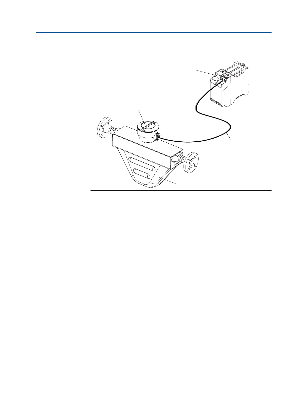
Sensor
Core processor
Transmitter
4-wire cable
Planning
4-wire remote installationFigure 1-1:
• Remote core processor with remote sensor
– A remote core process with remote
sensor installation separates all three components – transmitter, core processor,
and sensor – all of which are installed separately. A 4-wire cable connects the
transmitter to the core processor, and a 9-wire cable connects the core processor to
the sensor.
2 Micro Motion® Model 1500 and Model 2500
Page 7
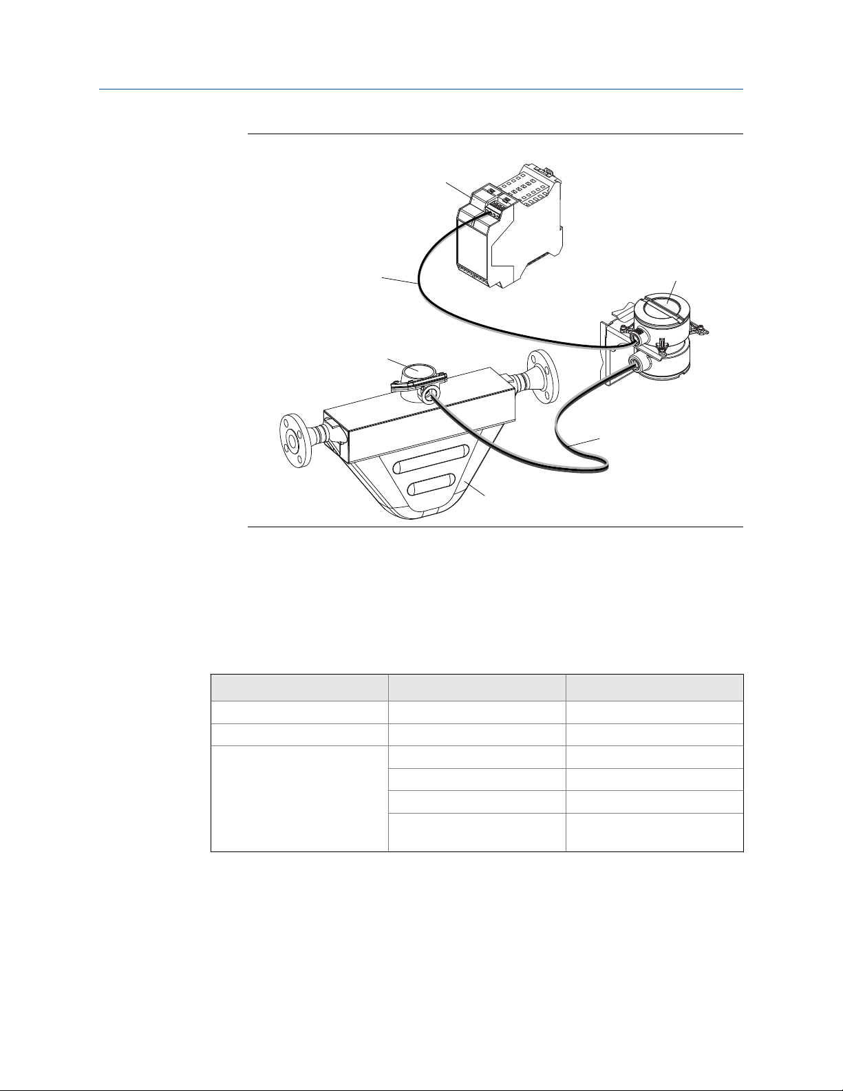
Core processor
Transmitter
4-wire cable
9-wire cable
Sensor
Junction box
Planning
Remote core processor with remote sensor installationFigure 1-2:
1.1.2 Maximum cable lengths
The maximum cable length between flowmeter components that are separately installed
is determined by cable type. See Table 1-1.
Maximum cable lengthsTable 1-1:
Cable type Wire gauge Maximum length
Micro Motion 4-wire Not applicable 1000 ft (300 m)
Micro Motion 9-wire Not applicable 60 ft (20 m)
User-supplied 4-wire VDC 22 AWG (0.35 mm2) 300 ft (90 m)
VDC 20 AWG (0.5 mm2) 500 ft (150 m)
VDC 18 AWG (0.8 mm2) 1000 ft (300 m)
RS-485 22 AWG (0.35 mm2) or
larger
1.2 Outputs option identification
You must know your transmitter's output option to correctly install the transmitter.
1000 ft (300 m)
Installation Manual 3
Page 8
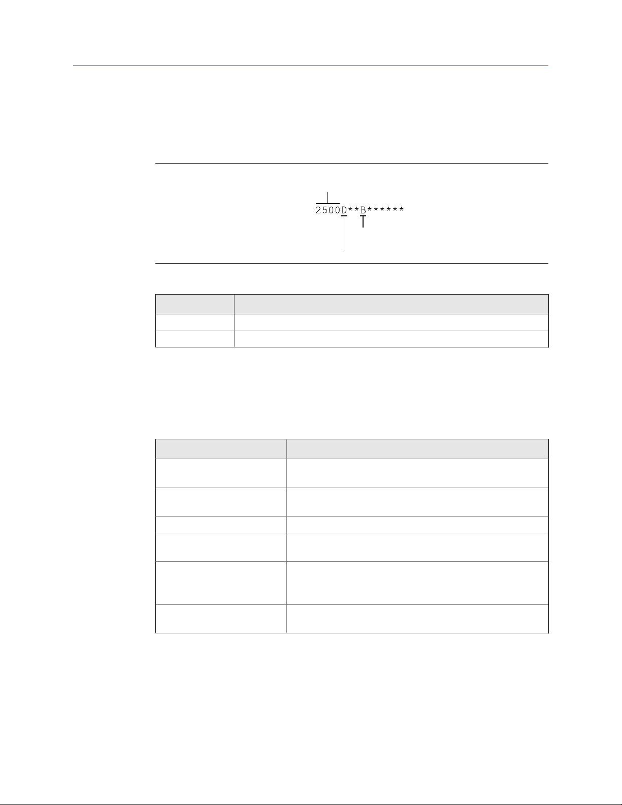
Transmitter type
Installation type
Output option
Planning
The transmitter's model number is on a tag on the side of the transmitter. You can use the
model number to determine the transmitter's output option. The first four characters are
the transmitter type. The fifth character is the installation type. The eighth character is the
output option. The remaining characters are not relevant to transmitter installation.
Model code identificationFigure 1-3:
Installation types for Model 1500 and Model 2500 transmittersTable 1-2:
Letter Description
D 4-wire remote 35 mm DIN rail
B 4-wire remote 35 mm DIN rail with 9-wire remote core processor
1.3 Environmental limits
Environmental specificationsTable 1-3:
Type Value
Ambient temperature limits
(Operating)
Ambient temperature limits
(Storage)
Humidity limits 5 to 95% relative humidity, non-condensing at 140 °F (60 °C)
Vibration limits Meets IEC68.2.6, endurance sweep, 5 to 2000 Hz, 50 sweep cy-
EMI effects Complies with EMC Directive 2004/108/EC per EN 61326 Indus-
Ambient temperature effect
(analog output option)
–40 to +131 °F (–40 to +55 °C)
–40 to +185 °F (–40 to +85 °C)
cles at 1.0 g
trial
Complies with NAMUR NE-21 (22.08.2007)
On mA output: ±0.005% of span per °C
1.4 Hazardous area classifications
If you plan to mount the transmitter in a hazardous area:
4 Micro Motion® Model 1500 and Model 2500
Page 9

• Verify that the transmitter has the appropriate hazardous area approval. Each
M
= 19.2V + (R × L × 0.33A)
transmitter has a hazardous area approval tag attached to the transmitter housing.
• Ensure that any cable used between the transmitter and the sensor meets the
hazardous area requirements.
1.5 Power requirements
The transmitter must be connected to a DC voltage source.
• Minimum 19.2 to 28.8 VDC
• 6.3 watts
• Meets Installation (Overvoltage) Category II, Pollution Degree 2 requirements
Cable sizing formulaFigure 1-4:
A. M: minimum supply voltage
B. R: cable resistance
C. L: cable length
Planning
Typical power cable resistance at 68 °F (20 °C)Table 1-4:
Wire gauge Resistance
14 AWG
16 AWG
18 AWG
20 AWG
2.5 mm
1.5 mm
1.0 mm
0.75 mm
0.50 mm
2
2
2
2
2
0.0050 Ω/ft
0.0080 Ω/ft
0.0128 Ω/ft
0.0204 Ω/ft
0.0136 Ω/m
0.0228 Ω/m
0.0340 Ω/m
0.0460 Ω/m
0.0680 Ω/m
Installation Manual 5
Page 10
A
B
C
Mounting and sensor wiring for 4-wire remote installations
2 Mounting and sensor wiring for 4-
wire remote installations
Topics covered in this chapter:
Mounting the transmitter to a DIN rail
•
Prepare the 4-wire cable
•
Wire the transmitter to the sensor
•
Ground the flowmeter components
•
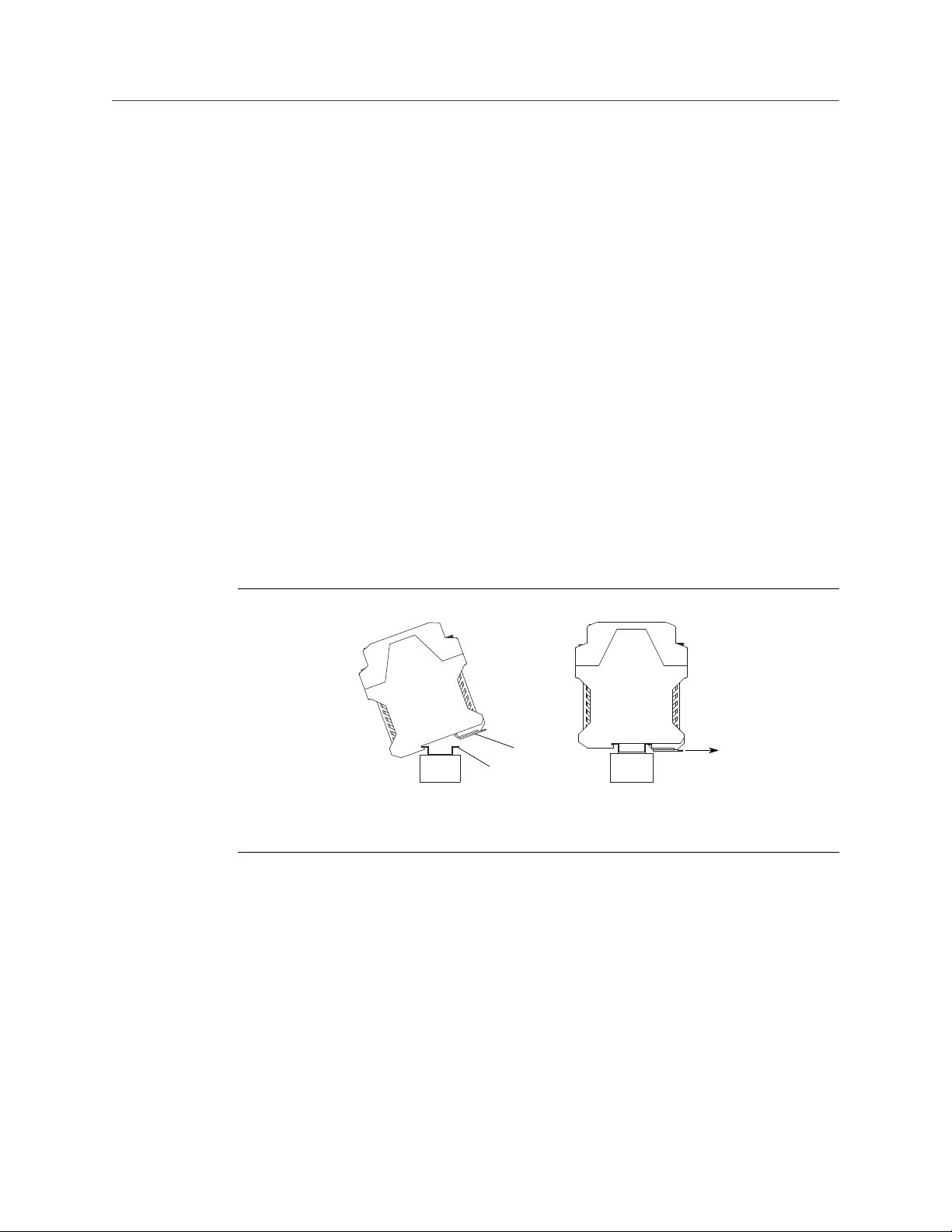
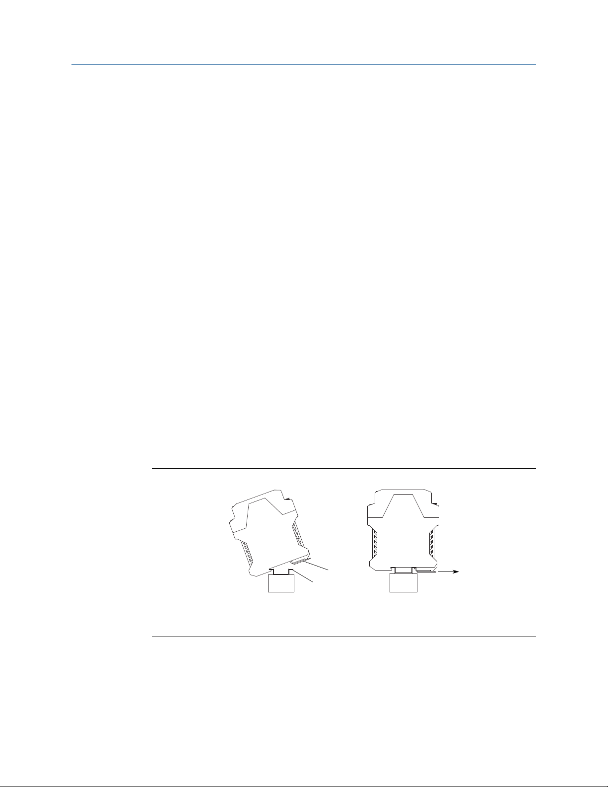
2.1 Mounting the transmitter to a DIN rail
The transmitter is designed to be mounted on a 35 mm DIN rail. The DIN rail must be
grounded.
2.1.1
Mounting the transmitterFigure 2-1:
A. Spring clamp
B. DIN rail
C. Spring clamp release loop
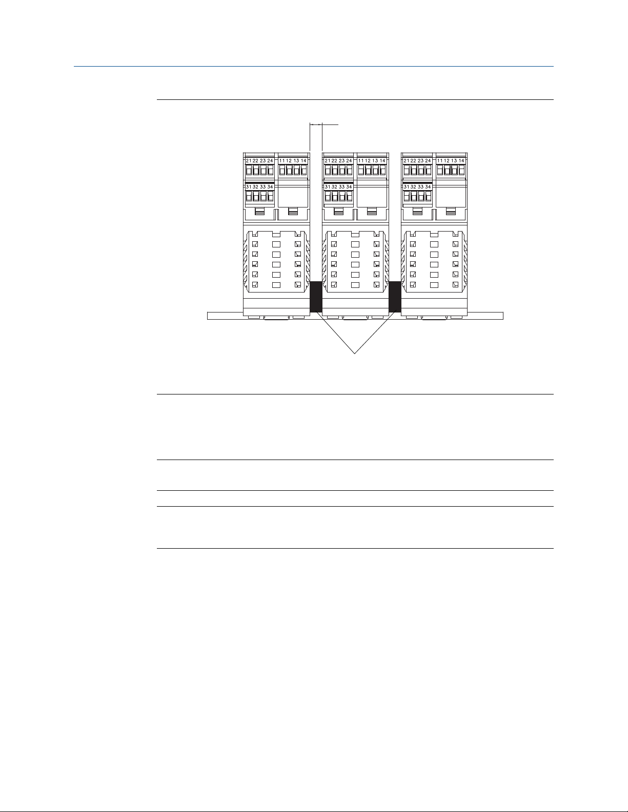
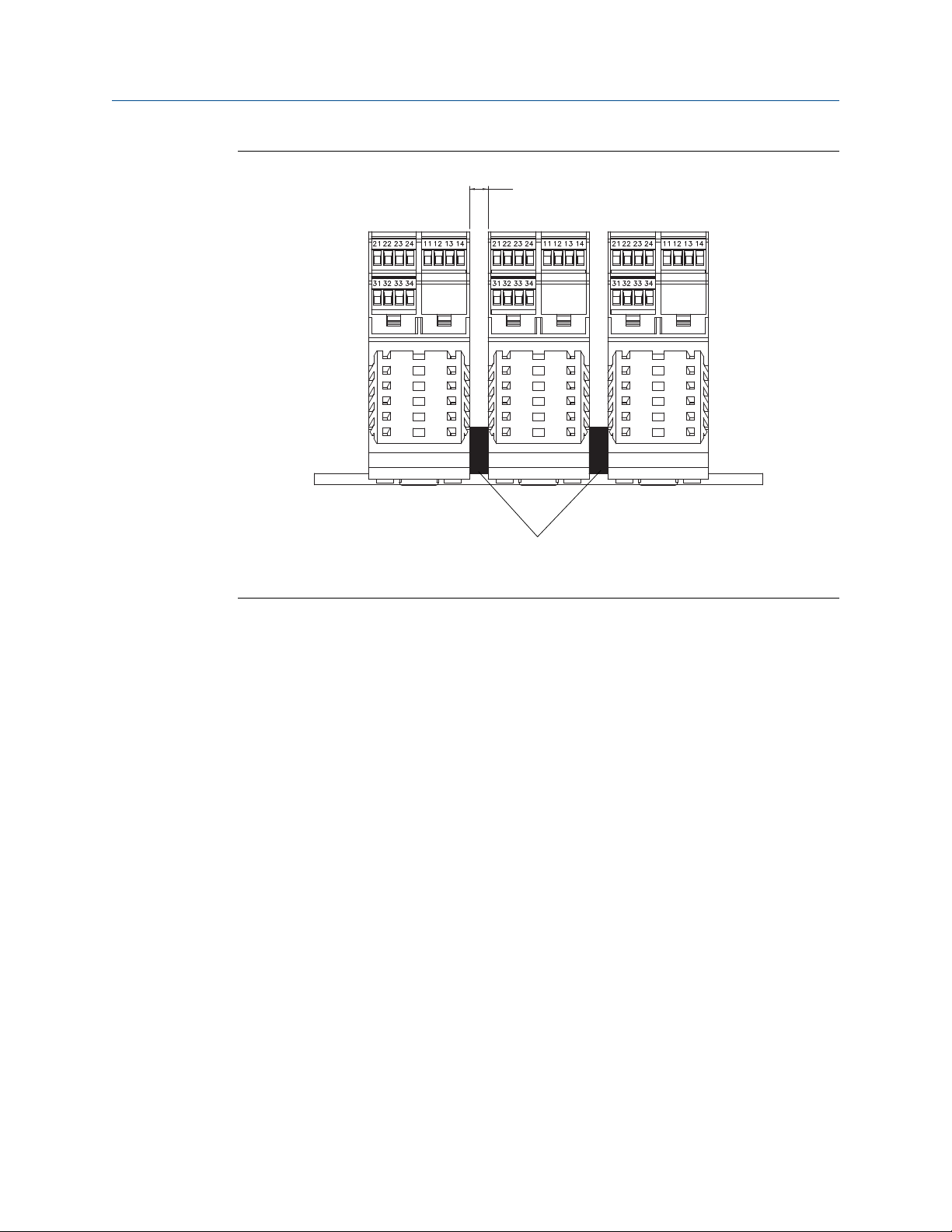
Mounting multiple transmitters
If the ambient temperature is above 113 °F (45 °C) and you are mounting multiple
transmitters, mount the transmitters so they are at least 0.33 in (8.5 mm) apart.
6 Micro Motion® Model 1500 and Model 2500
Page 11
A
Mounting and sensor wiring for 4-wire remote installations
Mounting multiple transmittersFigure 2-2:
2.2
A. 0.33 in or greater (8.5 mm or greater)
B. End bracket or end stop; 0.33 in (8.5 mm) minimum spacing
Prepare the 4-wire cable
Important
For user-supplied cable glands, the gland must be capable of terminating the drain wires.
Note
If you are installing unshielded cable in continuous metallic conduit with 360º termination shielding,
you only need to prepare the cable – you do not need to perform the shielding procedure.
Installation Manual 7
Page 12
Mounting and sensor wiring for 4-wire remote installations
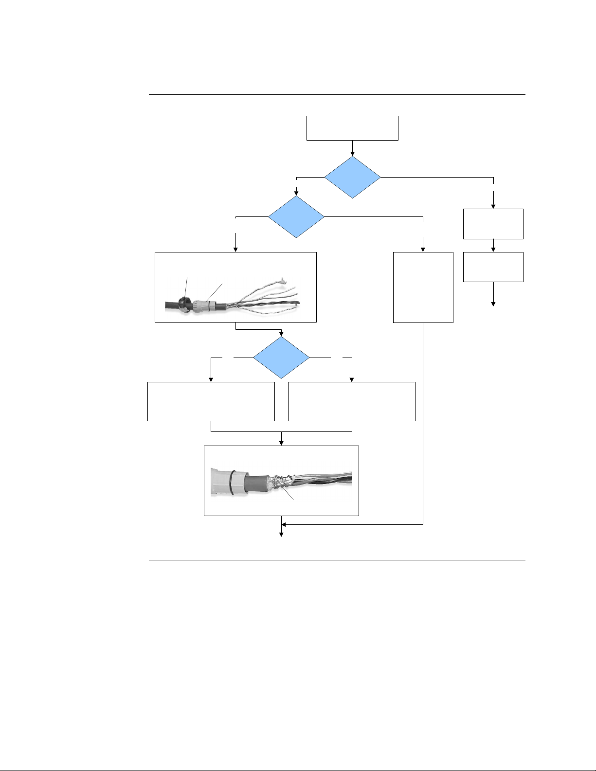
4-wire cable preparationFigure 2-3:
Remove the core processor
cover
Cable glands
Micro Motion
cable gland
Pass the wires through the gland nut and clamping insert.
Gland nut
1. Strip 4-1/2 inch (115 mm) of cable jacket.
2. Remove the clear wrap and filler material.
3. Strip all but 3/4 inch (19 mm) of shielding.
Clamping
insert
NPT
Wrap the drain wires twice around the shield and cut off
Gland supplier
Gland type
the excess drain wires.
Cable layout
through the gland.
Terminate the drain
wires inside the
M20
1. Strip 4-1/4 inch (108 mm) of cable jacket.
2. Remove the clear wrap and filler material.
3. Strip all but 1/2 inch (12 mm) of shielding.
User-supplied
cable gland
Pass the wires
gland.
Metal conduit
Run conduit to
sensor
Lay cable in conduit
Done
(do not perform the
shielding procedure)
Drain wires
wrapped around
shield
Go to the shielding
procedure
8 Micro Motion® Model 1500 and Model 2500
Page 13
Mounting and sensor wiring for 4-wire remote installations
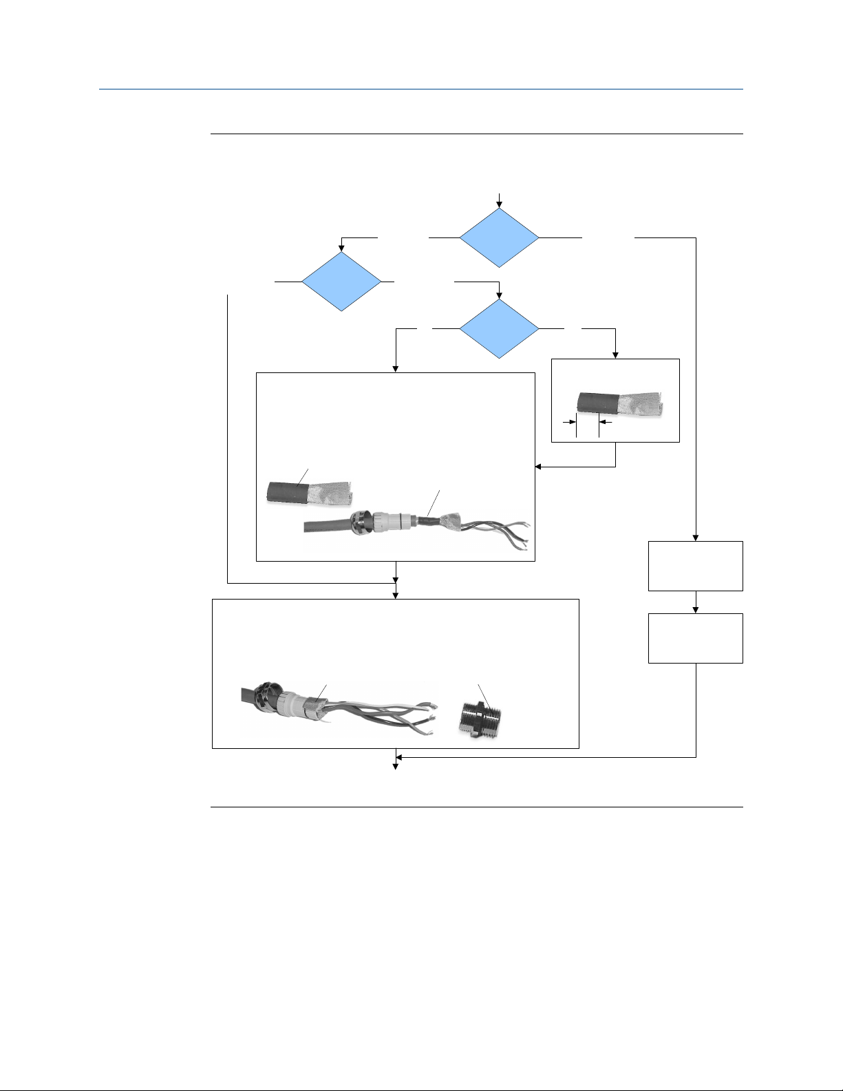
4-wire cable shieldingFigure 2-4:
From the preparation
procedure
Micro Motion
cable gland
Braided
(armored cable)
Apply the Heat Shrink
1. Slide the shielded heat shrink over the drain wires. Ensure that the
wires are completely covered.
2. Apply heat (250 °F or 120 °C) to shrink the tubing. Do not burn the
cable.
3. Position the clamping insert so the interior end is flush with the braid
of the heat shrink.
Assemble the Gland
1. Fold the shield or braid back over the clamping insert and 1/8 inch
(3 mm) past the O-ring.
2. Install the gland body into the conduit opening on the core processor housing.
3. Insert the wires through gland body and tighten the gland nut onto the gland body.
Cable shield
type
Shielded heat
shrink
Foil
(shielded cable)
NPT
Gland supplier
Gland type M20
After heat applied
User-supplied
cable gland
Trim 7 mm from the shielded
heat shrink
Trim
Terminate the shield
and drain wires in the
Assemble the gland
according to vendor
gland
instructions
Shield folded back
Done
Gland body
2.2.1 4-wire cable types and usage
Micro Motion offers two types of 4-wire cable: shielded and armored. Both types contain
shield drain wires.
The 4-wire cable supplied by Micro Motion consists of one pair of red and black 18 AWG
(0.75 mm2) wires for the VDC connection, and one pair of white and green 22 AWG
(0.35 mm2) wires for the RS-485 connection.
User-supplied 4-wire cable must meet the following requirements:
Installation Manual 9
Page 14
RS-485B
RS-485A
VDC–
VDC+
Mounting and sensor wiring for 4-wire remote installations
• Twisted pair construction.
• Applicable hazardous area requirements, if the core processor is installed in a
hazardous area.
• Wire gauge appropriate for the cable length between the core processor and the
transmitter.
Wire gaugeTable 2-1:
Wire gauge Maximum cable length
VDC 22 AWG (0.35 mm2) 300 ft (90 m)
VDC 20 AWG (0.5 mm2) 500 ft (150 m)
VDC 18 AWG (0.8 mm2) 1000 ft (300 m)
RS-485 22 AWG (0.35 mm2) or larger 1000 ft (300 m)
2.3 Wire the transmitter to the sensor
1. Connect the cable to the core processor as described in the sensor documentation.
2. Connect the four wires from the core processor to terminals 1–4 on the transmitter.
Important
Do not ground the shield, braid, or drain wires at the transmitter.
Terminal connections for 4-wire cableFigure 2-5:
2.4 Ground the flowmeter components
In 4-wire remote installations, the transmitter and sensor are grounded separately.
10 Micro Motion® Model 1500 and Model 2500
Page 15

Mounting and sensor wiring for 4-wire remote installations
CAUTION!
Improper grounding could cause inaccurate measurements or flow meter failure. Failure to
comply with requirements for intrinsic safety in a hazardous area could result in an explosion.
Note
For hazardous area installations in Europe, refer to standard EN 60079-14 or national standards.
If national standards are not in effect, adhere to the following guidelines for grounding:
• Use copper wire, 14 AWG (2.5 mm2) or larger wire size.
• Keep all ground leads as short as possible, less than 1 Ω impedance.
• Connect ground leads directly to earth, or follow plant standards.
1. Ground the sensor according to the instructions in the sensor documentation.
2. Ground the DIN rail.
The rail clip in the base of the transmitter housing grounds the transmitter to the
DIN rail.
Installation Manual 11
Page 16
A
B
C
Mounting and sensor wiring for remote core processor with remote sensor installations
3 Mounting and sensor wiring for
remote core processor with remote
sensor installations
Topics covered in this chapter:
Mounting the transmitter to a DIN rail
•
Mount the remote core processor
•
Prepare the 4-wire cable
•
Wire the transmitter to the remote core processor
•
Prepare the 9-wire cable
•
Wire the remote core processor to the sensor using jacketed cable
•
Wire the remote core processor to the sensor using shielded or armored cable
•
Ground the flowmeter components
•
3.1 Mounting the transmitter to a DIN rail
The transmitter is designed to be mounted on a 35 mm DIN rail. The DIN rail must be
grounded.
Mounting the transmitterFigure 3-1:
A. Spring clamp
B. DIN rail
C. Spring clamp release loop
3.1.1
Mounting multiple transmitters
If the ambient temperature is above 113 °F (45 °C) and you are mounting multiple
transmitters, mount the transmitters so they are at least 0.33 in (8.5 mm) apart.
12 Micro Motion® Model 1500 and Model 2500
Page 17
A
Mounting and sensor wiring for remote core processor with remote sensor installations
Mounting multiple transmittersFigure 3-2:
3.2
A. 0.33 in or greater (8.5 mm or greater)
B. End bracket or end stop; 0.33 in (8.5 mm) minimum spacing
Mount the remote core processor
This procedure is required only for remote core processor with remote transmitter
installations.
For mounting the remote core processor to a wall:
• Use four 5/16-inch diameter (or M8) bolts and nuts that can withstand the process
environment. Micro Motion does not supply bolts or nuts (appropriate bolts and
nuts are available as an option).
• Ensure that the surface is flat and rigid, does not vibrate, or move excessively.
For mounting the remote core processor to an instrument pole:
• Use two 5/16-inch U-bolts for 2-inch pipe, and four matching nuts, that can
withstand the process environment. Micro Motion does not supply U-bolts or nuts.
• Ensure the instrument pole extends at least 12 inches (305 mm) from a rigid base,
and is no more than 2 inches (50.8 mm) in diameter.
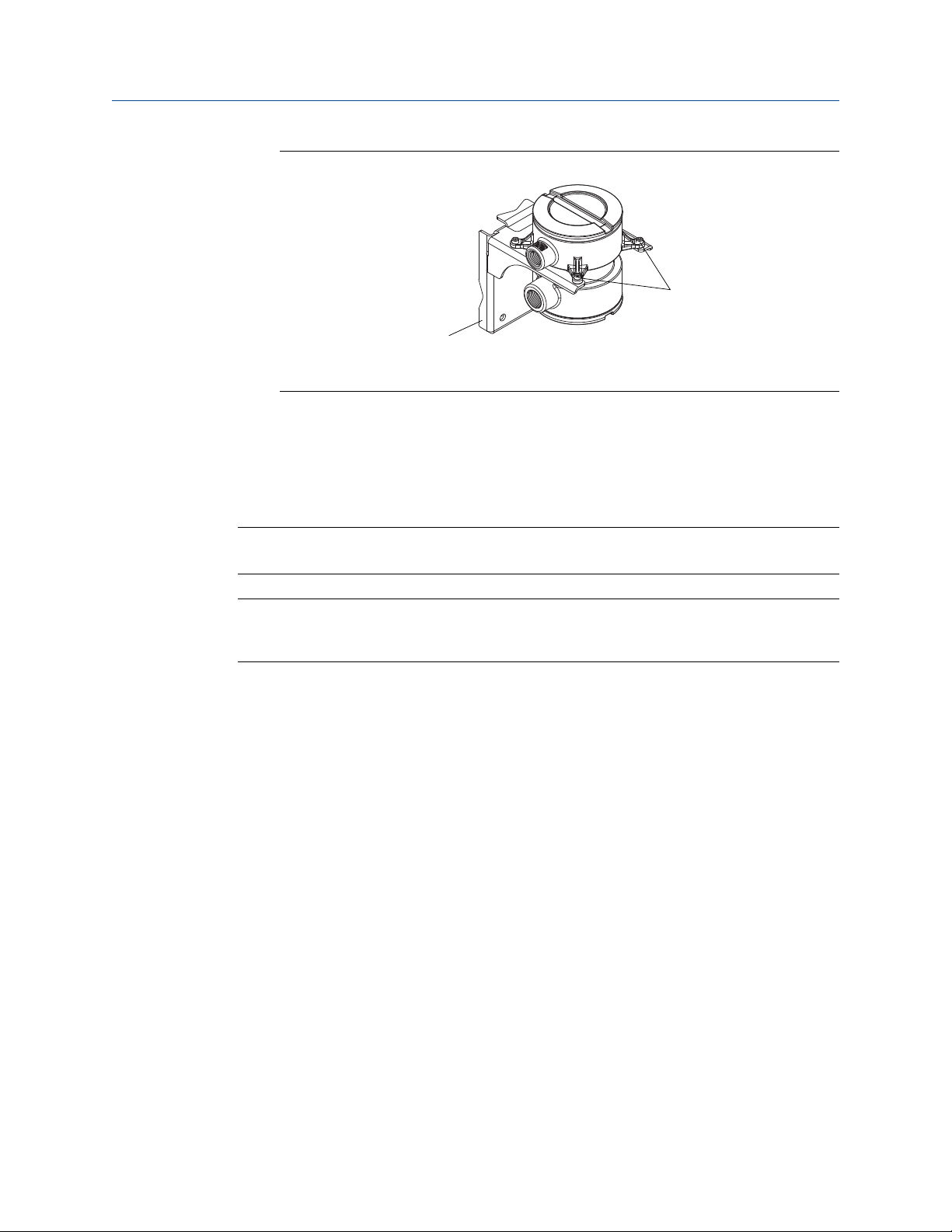
1. If desired, reorient the core processor housing on the bracket.
a. Loosen each of the four cap screws (4 mm).
b. Rotate the bracket so that the core processor is oriented as desired.
c. Tighten the cap screws, torquing to 30 to 38 in-lbs (3 to 4 N-m).
Installation Manual 13
Page 18
A
B
Mounting and sensor wiring for remote core processor with remote sensor installations
Components of a remote core processorFigure 3-3:
A. Mounting bracket
B. Cap screws
2. Attach the mounting bracket to an instrument pole or wall.
3.3 Prepare the 4-wire cable
Important
For user-supplied cable glands, the gland must be capable of terminating the drain wires.
Note
If you are installing unshielded cable in continuous metallic conduit with 360º termination shielding,
you only need to prepare the cable – you do not need to perform the shielding procedure.
14 Micro Motion® Model 1500 and Model 2500
Page 19

Mounting and sensor wiring for remote core processor with remote sensor installations
4-wire cable preparationFigure 3-4:
Remove the core processor
cover
Cable glands
Micro Motion
cable gland
Pass the wires through the gland nut and clamping insert.
Gland nut
1. Strip 4-1/2 inch (115 mm) of cable jacket.
2. Remove the clear wrap and filler material.
3. Strip all but 3/4 inch (19 mm) of shielding.
Clamping
insert
NPT
Wrap the drain wires twice around the shield and cut off
Gland supplier
Gland type
the excess drain wires.
Cable layout
through the gland.
Terminate the drain
wires inside the
M20
1. Strip 4-1/4 inch (108 mm) of cable jacket.
2. Remove the clear wrap and filler material.
3. Strip all but 1/2 inch (12 mm) of shielding.
User-supplied
cable gland
Pass the wires
gland.
Metal conduit
Run conduit to
sensor
Lay cable in conduit
Done
(do not perform the
shielding procedure)
Drain wires
wrapped around
shield
Go to the shielding
procedure
Installation Manual 15
Page 20

Mounting and sensor wiring for remote core processor with remote sensor installations
4-wire cable shieldingFigure 3-5:
From the preparation
procedure
Micro Motion
cable gland
Braided
(armored cable)
Apply the Heat Shrink
1. Slide the shielded heat shrink over the drain wires. Ensure that the
wires are completely covered.
2. Apply heat (250 °F or 120 °C) to shrink the tubing. Do not burn the
cable.
3. Position the clamping insert so the interior end is flush with the braid
of the heat shrink.
Assemble the Gland
1. Fold the shield or braid back over the clamping insert and 1/8 inch
(3 mm) past the O-ring.
2. Install the gland body into the conduit opening on the core processor housing.
3. Insert the wires through gland body and tighten the gland nut onto the gland body.
Cable shield
type
Shielded heat
shrink
Foil
(shielded cable)
NPT
Gland supplier
Gland type M20
After heat applied
User-supplied
cable gland
Trim 7 mm from the shielded
heat shrink
Trim
Terminate the shield
and drain wires in the
Assemble the gland
according to vendor
gland
instructions
Shield folded back
Done
Gland body
3.3.1 4-wire cable types and usage
Micro Motion offers two types of 4-wire cable: shielded and armored. Both types contain
shield drain wires.
The 4-wire cable supplied by Micro Motion consists of one pair of red and black 18 AWG
(0.75 mm2) wires for the VDC connection, and one pair of white and green 22 AWG
(0.35 mm2) wires for the RS-485 connection.
User-supplied 4-wire cable must meet the following requirements:
16 Micro Motion® Model 1500 and Model 2500
Page 21

A
Mounting and sensor wiring for remote core processor with remote sensor installations
• Twisted pair construction.
• Applicable hazardous area requirements, if the core processor is installed in a
hazardous area.
• Wire gauge appropriate for the cable length between the core processor and the
transmitter.
Wire gaugeTable 3-1:
Wire gauge Maximum cable length
VDC 22 AWG (0.35 mm2) 300 ft (90 m)
VDC 20 AWG (0.5 mm2) 500 ft (150 m)
VDC 18 AWG (0.8 mm2) 1000 ft (300 m)
RS-485 22 AWG (0.35 mm2) or larger 1000 ft (300 m)
3.4 Wire the transmitter to the remote core processor
1. If you are installing a Micro Motion-supplied cable gland at the core processor
housing, identify the cable gland to use for the 4-wire cable conduit opening.
Cable gland identificationFigure 3-6:
A. Cable gland used with 4-wire conduit opening
B. 3/4"–14 NPT cable gland used with 9-wire conduit opening
2. Connect the cable to the core processor as described in the sensor documentation.
3. Connect the four wires from the core processor to terminals 1–4 on the transmitter.
Important
Do not ground the shield, braid, or drain wires at the transmitter.
Installation Manual 17
Page 22

RS-485B
RS-485A
VDC–
VDC+
Mounting and sensor wiring for remote core processor with remote sensor installations
Terminal connections for 4-wire cableFigure 3-7:
3.5 Prepare the 9-wire cable
Micro Motion supplies three types of 9-wire cable: jacketed, shielded, and armored. The
type of cable you are using determines how you will prepare the cable.
Perform the cable preparation procedure appropriate for your cable type.
18 Micro Motion® Model 1500 and Model 2500
Page 23

Mounting and sensor wiring for remote core processor with remote sensor installations
Preparing jacketed cableFigure 3-8:
Prepare jacketed
cable at the sensor
end
1. Trim 4 ½ inches (115 mm) of cable jacket.
2. Remove the clear wrap and filler material.
3. Remove the foil that is around the insulated wires
and separate them.
Trim cable jacket
4. Identify the drain wires in the cable. Clip off each
drain wire as close as possible to the cable jacket.
Drain wires clipped
5. Slide the 1 ½ inch (40 mm) heat-shrink tubing over
the wires and cable jacket. The tubing should
completely cover the clipped ends of the drain wires.
Prepare jacketed
cable at the
transmitter end
1. Trim 4 inches (100 mm) of cable jacket.
2. Remove the clear wrap and filler material.
3. Remove the foil that is around the insulated wires
and separate them.
Trim cable jacket
4. Identify the drain wires in the cable and bring them
together. Fan the other wires to the outside of the
cable. Twist the drain wires together.
5. Slide the 3-inch (75 mm) heat-shrink tubing over
the drain wires. Push the tubing as close as possible
to the cable jacket.
6. Slide the 1 ½ inch (40 mm) long heat-shrink tubing
over the cable jacket. The tubing should
completely cover all portions of the drain wires that
remain exposed next to the cable jacket.
Heat-shrink
tubing
6. Without burning the cable, apply heat to shrink all
tubing. Recommended temperature is 250 °F (121
°C).
7. Allow the cable to cool, then strip ¼ inch (5 mm) of
insulation from each wire.
Heat-shrink tubing over
cable jacket
Heat-shrink tubing over drain
wires
7. Without burning the cable, apply heat to shrink all
tubing. Recommended temperature is 250 °F (121
°C).
8. Allow the cable to cool, then strip ¼ inch (5 mm) of
insulation from each wire.
Installation Manual 19
Page 24

Mounting and sensor wiring for remote core processor with remote sensor installations
Preparing shielded or armored cableFigure 3-9:
Prepare shielded or
armored cable at the
sensor end
1. Without cutting the shield, strip 7 inches (175 mm)
of outer jacket.
2. Strip 6 ½ inches (165 mm) of braided shield, so ½
inch (10 mm) of shield remains exposed.
3. Remove the foil shield that is between the braided
shield and inner jacket.
4. Strip 4 ½ inches (115 mm) of inner jacket.
Trim outer jacket
Trim braided shield
Trim inner jacket
5. Remove the clear wrap and filler material.
6. Remove the foil that is around the insulated wires
and separate them.
7. Identify the drain wires in the cable. Clip each drain
wire as close as possible to the cable jacket.
Drain wires clipped
8. Slide the 1 ½ inch (40 mm) long heat-shrink tubing
over the cable jacket. The tubing should completely
cover the clipped ends of the drain wires.
Prepare shielded or
armored cable at the
transmitter end
1. Without cutting the shield, strip 9 inches (225 mm) of
cable jacket.
2. Strip 8 ½ inches (215 mm) of braided shield, so ½
inch (10 mm) of shield remains exposed.
3. Remove the foil shield that is between the braided
shield and inner jacket.
4. Strip 4 inches (100 mm) of inner jacket.
Trim outer jacket
Trim braided shield
Trim inner jacket
5. Remove the clear wrap and filler material.
6. Remove the foil that is around the insulated wires and
separate them.
7. Identify the drain wires in the cable and bring them
together. Fan the other wires to the outside of the
cable. Twist the drain wires together.
8. Slide the 3-inch (75 mm) long heat-shrink tubing over
the drain wires. Push the tubing as close as possible to
the inner jacket.
9. Slide the 1 ½ inch (40 mm) long heat-shrink tubing
over the cable jacket. The tubing should completely
cover all portions of the drain wires that remain
exposed next to the cable jacket.
Heat-shrink tubing
9. Without burning the cable, apply heat to shrink all
tubing. Recommended temperature is 250 °F (121
°C).
10. Allow the cable to cool, then strip ¼ inch (5 mm) of
insulation from each wire.
Heat-shrink tubing over cable
Heat-shrink tubing over drain wires
10. Without burning the cable, apply heat to shrink all
tubing. Recommended temperature is 250 °F (121
°C).
11. Allow the cable to cool, then strip ¼ inch (5 mm) of
insulation from each wire.
jacket
3.5.1 9-wire cable types and usage
20 Micro Motion® Model 1500 and Model 2500
Page 25

Mounting and sensor wiring for remote core processor with remote sensor installations
Cable types
Micro Motion supplies three types of 9-wire cable: jacketed, shielded, and armored. Note
the following differences between the cable types:
• Armored cable provides mechanical protection for the cable wires.
• Jacketed cable has a smaller bend radius than shielded or armored cable.
• If ATEX compliance is required, the different cable types have different installation
requirements.
Cable jacket types
All cable types can be ordered with a PVC jacket or Teflon® FEP jacket. Teflon FEP is
required for the following installation types:
• All installations that include a T-series sensor.
• All installations with a cable length of 250 ft (75 m) or greater, a nominal flow less
than 20 percent, and ambient temperature changes greater than +68 °F (+20 °C).
Cable jacket material and temperature rangesTable 3-2:
Handling temperature Operating temperature
Cable jacket material Low limit High limit Low limit High limit
PVC –4 °F (–20 °C) +194 °F (+90 °C) –40 °F (–40 °C) +221 °F (+105 °C)
Teflon FEP –40 °F (–40 °C) +194 °F (+90 °C) –76 °F (–60 °C) +302 °F (+150 °C)
Cable bend radii
Bend radii of jacketed cableTable 3-3:
Jacket material Outside diameter Minimum bend radii
Static (no load) condition Under dynamic load
PVC 0.415 inches (10 mm) 3–1/8 inches (80 mm) 6–1/4 inches (159 mm)
Teflon FEP 0.340 inches (9 mm) 2–5/8 inches (67 mm) 5–1/8 inches (131 mm)
Bend radii of shielded cableTable 3-4:
Jacket material Outside diameter Minimum bend radii
Static (no load) condition Under dynamic load
PVC 0.2 inches (14 mm) 4–1/4 inches (108 mm) 8–1/2 inches (216 mm)
Teflon FEP 0.425 inches (11 mm) 3–1/4 inches (83 mm) 6–3/8 inches (162 mm)
Installation Manual 21
Page 26

A
C (4)
B (4)
D (5)
Mounting and sensor wiring for remote core processor with remote sensor installations
Bend radii of armored cableTable 3-5:
Jacket material Outside diameter Minimum bend radii
Static (no load) condition Under dynamic load
PVC 0.525 inches (14 mm) 4–1/4 inches (108 mm) 8–1/2 inches (216 mm)
Teflon FEP 0.340 inches (9 mm) 3–1/4 inches (83 mm) 6–3/8 inches (162 mm)
Cable illustrations
Cross-section view of jacketed cableFigure 3-10:
A. Outer jacket
B. Drain wire (4 total)
C. Foil shield (4 total)
D. Filler (5 total)
22 Micro Motion® Model 1500 and Model 2500
Page 27

A
C (1)
B
D
E (4)
F (4)
G (5)
A
C (1)
B
D
E (4)
F (4)
G (5)
Mounting and sensor wiring for remote core processor with remote sensor installations
Cross-section view of shielded cableFigure 3-11:
A. Outer jacket
B. Tin-plated copper braided shield
C. Foil shield (1 total)
D. Inner jacket
E. Drain wire (4 total)
F. Foil shield (4 total)
G. Filler (5 total)
Cross-section view of armored cableFigure 3-12:
A. Outer jacket
B. Stainless steel braided shield
C. Foil shield (1 total)
D. Inner jacket
E. Drain wire (4 total)
F. Foil shield (4 total)
G. Filler (5 total)
Installation Manual 23
Page 28

Mounting and sensor wiring for remote core processor with remote sensor installations
3.6 Wire the remote core processor to the sensor using jacketed cable
For ATEX installations, the jacketed cable must be installed inside a user-supplied sealed
metallic conduit that provides 360° termination shielding for the enclosed cable.
CAUTION!
Sensor wiring is intrinsically safe. To keep sensor wiring intrinsically safe, keep the sensor
wiring separated from power supply wiring and output wiring.
CAUTION!
Keep cable away from devices such as transformers, motors, and power lines, which produce
large magnetic fields. Improper installation of cable, cable gland, or conduit could cause
inaccurate measurements or flow meter failure.
CAUTION!
Improperly sealed housings can expose electronics to moisture, which can cause measurement
error or flowmeter failure. Install drip legs in conduit and cable, if necessary. Inspect and
grease all gaskets and O-rings. Fully close and tighten all housing covers and conduit openings.
1. Run the cable through the conduit. Do not install 9-wire cable and power cable in
the same conduit.
2. To prevent conduit connectors from seizing in the threads of the conduit openings,
apply a conductive anti-galling compound to the threads, or wrap threads with PTFE
tape two to three layers deep.
Wrap the tape in the opposite direction that the male threads will turn when
inserted into the female conduit opening.
3. Remove the junction box cover and core processor end-cap.
4. At both the sensor and transmitter, do the following:
a. Connect a male conduit connector and waterproof seal to the conduit opening
for 9-wire.
b. Pass the cable through the conduit opening for the 9-wire cable.
c. Insert the stripped end of each wire into the corresponding terminal at the
sensor and transmitter ends, matching by color. No bare wires should remain
exposed.
Sensor and remote core processor terminal designationsTable 3-6:
Wire color Sensor terminal Remote core processor terminal Function
Black No connection Ground screw (see note) Drain wires
Brown 1 1 Drive +
Red 2 2 Drive –
24 Micro Motion® Model 1500 and Model 2500
Page 29

Mounting and sensor wiring for remote core processor with remote sensor installations
Table 3-6:
Wire color Sensor terminal Remote core processor terminal Function
Orange 3 3 Temperature –
Yellow 4 4 Temperature return
Green 5 5 Left pickoff +
Blue 6 6 Right pickoff +
Violet 7 7 Temperature +
Gray 8 8 Right pickoff –
White 9 9 Left pickoff –
Note
Ground the shield drain wires (the black wire) only on the core processor end, by
connecting it to the ground screw inside the lower conduit ring. Never ground to the core
processor’s mounting screw. Never ground the cable at the sensor junction box.
Sensor and remote core processor terminal designations
(continued)
d. Tighten the screws to hold the wire in place.
e. Ensure integrity of gaskets, grease all O-rings, then replace the junction-box and
transmitter housing covers and tighten all screws, as required.
3.6.1
Sensor and remote core processor terminals
Installation Manual 25
Page 30

D
I
H
F
E
A
B
C
G
Mounting and sensor wiring for remote core processor with remote sensor installations
ELITE, H-Series, T-Series, and some F-Series sensor terminalsFigure 3-13:
A. Violet
B. Yellow
C. Orange
D. Brown
E. White
F. Green
G. Red
H. Gray
I. Blue
F-Series, Model D, and Model DL sensor terminalsFigure 3-14:
26 Micro Motion® Model 1500 and Model 2500
Page 31

1
9
8
7
6
5
4
3
2
A
A
B
C
D
E
F
G
H
I
J
K
Mounting and sensor wiring for remote core processor with remote sensor installations
Figure 3-15:
Model DT sensor terminals (user-supplied metal junction box with
terminal block)
A. Earth ground
Remote core processor terminalsFigure 3-16:
A. Brown
B. Violet
C. Yellow
D. Orange
E. Gray
F. Blue
G. White
H. Green
I. Red
J. Mounting screw
K. Ground screw (black)
Installation Manual 27
Page 32

A
B
C
D
E
F
G
H
I
Mounting and sensor wiring for remote core processor with remote sensor installations
3.7 Wire the remote core processor to the sensor using shielded or armored cable
For ATEX installations, shielded or armored cable must be installed with cable glands, at
both the sensor and remote core processor ends. Cable glands that meet ATEX
requirements can be purchased from Micro Motion. Cable glands from other vendors can
be used.
CAUTION!
Keep cable away from devices such as transformers, motors, and power lines, which produce
large magnetic fields. Improper installation of cable, cable gland, or conduit could cause
inaccurate measurements or flow meter failure.
CAUTION!
Install cable glands in the 9-wire conduit opening in the transmitter housing and the sensor
junction box. Ensure that the cable drain wires and shields do not make contact with the
junction box or the transmitter housing. Improper installation of cable or cable glands could
cause inaccurate measurements or flow meter failure.
CAUTION!
Improperly sealed housings can expose electronics to moisture, which can cause measurement
error or flowmeter failure. Install drip legs in conduit and cable, if necessary. Inspect and
grease all gaskets and O-rings. Fully close and tighten all housing covers and conduit openings.
1. Identify the components of the cable gland and cable.
Cable gland and cable (exploded view)Figure 3-17:
A. Cable
B. Sealing nut
C. Compression nut
D. Brass compression ring
E. Braided shield
F. Cable
G. Tape or heat-shrink tubing
H. Clamp seat (shown as integral to nipple)
I. Nipple
2. Unscrew the nipple from the compression nut.
28 Micro Motion® Model 1500 and Model 2500
Page 33

A
B
C
D
E F
G
A
Mounting and sensor wiring for remote core processor with remote sensor installations
3. Screw the nipple into the conduit opening for the 9-wire cable. Tighten it to one turn
past hand-tight.
4. Slide the compression ring, compression nut, and sealing nut onto the cable. Make
sure the compression ring is oriented so the taper will mate properly with the
tapered end of the nipple.
5. Pass the cable end through the nipple so the braided shield slides over the tapered
end of the nipple.
6. Slide the compression ring over the braided shield.
7. Screw the compression nut onto the nipple. Tighten the sealing nut and
compression nut by hand to ensure that the compression ring traps the braided
shield.
8. Use a 25-mm (1-inch) wrench to tighten the sealing nut and compression nut to
20–25 foot-pounds (27–34 N-m) of torque.
Cross-section of assembled cable gland with cableFigure 3-18:
A. Cable
B. Sealing nut
C. Seal
D. Compression nut
E. Braided shield
F. Brass compression ring
G. Nipple
9. Remove the junction box cover and remote core processor end-cap.
10. At both the sensor and remote core processor, connect the cable according to the
following procedure:
a. Insert the stripped end of each wire into the corresponding terminal at the
sensor and remote core processor ends, matching by color. No bare wires should
remain exposed.
Installation Manual 29
Page 34

Mounting and sensor wiring for remote core processor with remote sensor installations
Sensor and remote core processor terminal designationsTable 3-7:
Wire color Sensor terminal Remote core processor terminal Function
Black No connection Ground screw (see notes) Drain wires
Brown 1 1 Drive +
Red 2 2 Drive –
Orange 3 3 Temperature –
Yellow 4 4 Temperature return
Green 5 5 Left pickoff +
Blue 6 6 Right pickoff +
Violet 7 7 Temperature +
Gray 8 8 Right pickoff –
White 9 9 Left pickoff –
Notes
• Ground the shield drain wires (the black wire) only on the remote core processor end,
by connecting it to the ground screw inside the lower conduit ring. Never ground to
the core processor’s mounting screw. Never ground the cable at the sensor junction
box.
• Ground the cable braid on both ends, by terminating it inside the cable glands.
3.7.1
b. Tighten the screws to hold the wires in place.
c. Ensure integrity of gaskets, grease all O-rings, then replace the junction box
cover and remote core processor end-cap and tighten all screws, as required.
Sensor and remote core processor terminals
30 Micro Motion® Model 1500 and Model 2500
Page 35

D
I
H
F
E
A
B
C
G
A. Violet
B. Yellow
C. Orange
D. Brown
E. White
F. Green
G. Red
H. Gray
I. Blue
Mounting and sensor wiring for remote core processor with remote sensor installations
ELITE, H-Series, T-Series, and some F-Series sensor terminalsFigure 3-19:
F-Series, Model D, and Model DL sensor terminalsFigure 3-20:
Installation Manual 31
Page 36

1
9
8
7
6
5
4
3
2
A
A
B
C
D
E
F
G
H
I
J
K
Mounting and sensor wiring for remote core processor with remote sensor installations
Figure 3-21:
Model DT sensor terminals (user-supplied metal junction box with
terminal block)
A. Earth ground
Remote core processor terminalsFigure 3-22:
A. Brown
B. Violet
C. Yellow
D. Orange
E. Gray
F. Blue
G. White
H. Green
I. Red
J. Mounting screw
K. Ground screw (black)
32 Micro Motion® Model 1500 and Model 2500
Page 37

Mounting and sensor wiring for remote core processor with remote sensor installations
3.8 Ground the flowmeter components
In a remote core processor with remote sensor installation, the transmitter, remote core
processor, and sensor are all grounded separately.
CAUTION!
Improper grounding could cause inaccurate measurements or flow meter failure. Failure to
comply with requirements for intrinsic safety in a hazardous area could result in an explosion.
Note
For hazardous area installations in Europe, refer to standard EN 60079-14 or national standards.
If national standards are not in effect, adhere to the following guidelines for grounding:
• Use copper wire, 14 AWG (2.5 mm2) or larger wire size.
• Keep all ground leads as short as possible, less than 1 Ω impedance.
• Connect ground leads directly to earth, or follow plant standards.
1. Ground the sensor according to the instructions in the sensor documentation.
2. Ground the DIN rail.
The rail clip in the base of the transmitter housing grounds the transmitter to the
DIN rail.
3. Ground the remote core processor according to applicable local standards, using
the remote core processor’s internal ground screw.
Remote core processor internal ground screwFigure 3-23:
Installation Manual 33
Page 38

A
B
Wiring the power supply
4 Wiring the power supply
4.1 Wire the power supply
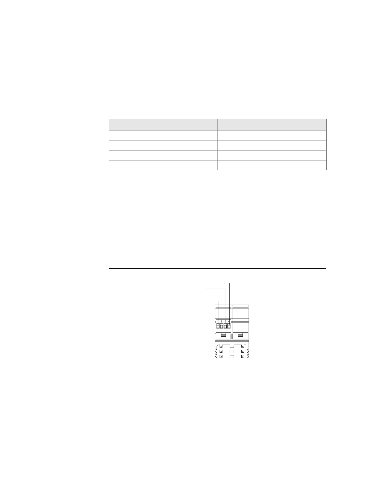
Connect the power supply to terminals 11 and 12. Terminals 13 and 14 are used to jumper
power to another Model 1500 or Model 2500 transmitter. A maximum of five transmitters
can be jumpered together.
Power terminalsFigure 4-1:
A. Primary power supply (VDC)
B. Power supply jumper to 1–4 additional Model 1500 or Model 2500 transmitters
34 Micro Motion® Model 1500 and Model 2500
Page 39

5 I/O wiring for Model 1500
A
transmitters
Topics covered in this chapter:
Basic analog wiring
•
HART/analog single loop wiring
•
HART multidrop wiring
•
5.1 Basic analog wiring
Model 1500 basic analog wiringFigure 5-1:
I/O wiring for Model 1500 transmitters
A. Terminals 21 and 22 to mA receiving device; 820 Ω maximum loop resistance
5.2
Installation Manual 35
HART/analog single loop wiring
Note
For HART communications:
600 Ω maximum loop resistance
•
250 Ω minimum loop resistance
•
Page 40

A
B
A
B
C
D
E
F
I/O wiring for Model 1500 transmitters
HART/analog single loop wiringFigure 5-2:
820 Ω maximum loop resistance
A.
B. HART-compatible host or controller
5.3 HART multidrop wiring
Tip
For optimum HART communication, single-point ground the output loop to an instrument-grade
ground.
HART multidrop wiringFigure 5-3:
A. 250–600 Ω resistance
B. HART-compatible host or controller
C. HART-compatible transmitters
D. Model 1500 or Model 2500 transmitter
E. SMART FAMILY™ transmitters
F. 24 VDC loop power supply required for passive transmitters
36 Micro Motion® Model 1500 and Model 2500
Page 41

6 I/O wiring for Model 2500
A B
transmitters
Topics covered in this chapter:
mA/HART wiring
•
Frequency output wiring
•
Discrete output wiring
•
Discrete input wiring
•
6.1 mA/HART wiring
I/O wiring for Model 2500 transmitters
6.1.1 Basic analog wiring
Model 2500 basic analog wiringFigure 6-1:
A. Channel A – Terminals 21 and 22 to mA receiving device; 820 Ω maximum loop resistance
B. Channel B – Terminals 23 and 24 to mA receiving device; 420 Ω maximum loop resistance
6.1.2
HART/analog single loop wiring
Note
For HART communications:
600 Ω maximum loop resistance
•
250 Ω minimum loop resistance
•
Installation Manual 37
Page 42

A
B
A
B
C
D
E
F
I/O wiring for Model 2500 transmitters
HART/analog single loop wiringFigure 6-2:
820 Ω maximum loop resistance
A.
B. HART-compatible host or controller
6.1.3 HART multidrop wiring
Tip
For optimum HART communication, single-point ground the output loop to an instrument-grade
ground.
HART multidrop wiringFigure 6-3:
A. 250–600 Ω resistance
B. HART-compatible host or controller
C. HART-compatible transmitters
D. Model 1500 or Model 2500 transmitter
E. SMART FAMILY™ transmitters
F. 24 VDC loop power supply required for passive transmitters
38 Micro Motion® Model 1500 and Model 2500
Page 43

A
B
C
A
I/O wiring for Model 2500 transmitters
6.2 Frequency output wiring
6.2.1 Internally powered frequency output wiring
Internally powered frequency output wiringFigure 6-4:
A. Counter
B. Channel B – Terminals 23 and 24
C. Channel C – Terminals 31 and 32
Installation Manual 39
Page 44

Open circuit output voltage = 15 VDC ±3%
Load resistance (Ohms)
High level output voltage (Volts)
I/O wiring for Model 2500 transmitters
16
14
12
10
8
6
High level output voltage (Volts)
4
2
Output voltage versus load resistance (Channel B)Figure 6-5:
Maximum output voltage = 15 VDC ± 3%
0
0 500 1000 1500 2000 2500
Load resistance (Ohms)
Output voltage versus load resistance (Channel C)Figure 6-6:
40 Micro Motion® Model 1500 and Model 2500
Page 45

A
A
B
C
D
D
E
I/O wiring for Model 2500 transmitters
6.2.2 Externally powered frequency output wiring
Externally powered frequency output wiringFigure 6-7:
A. Counter
B. Channel B – Terminals 23 and 24
C. Channel C – Terminals 31 and 32
D. 3–30 VDC
E. Pull-up reisistor
CAUTION!
Exceeding 30 VDC can damage the transmitter. Terminal current must be less than 500 mA.
Installation Manual 41
Page 46

I/O wiring for Model 2500 transmitters
4400
4000
3600
3200
2800
2400
2000
1600
External pull-up resistor range (Ohms)
1200
800
Recommended pull-up resistor versus supply voltageFigure 6-8:
0
5 10 15 20 25 30
Supply voltage (Volts)
6.3 Discrete output wiring
6.3.1 Internally powered discrete output wiring
42 Micro Motion® Model 1500 and Model 2500
Page 47

Internally powered discrete output wiringFigure 6-9:
A
A
B
C
A. Discrete output receiving device
B. Channel B (DO1) – Terminals 23 and 24
C. Channel C (DO2) – Terminals 31 and 32
I/O wiring for Model 2500 transmitters
Output voltage versus load resistance (Channel B)Figure 6-10:
Maximum output voltage = 15 VDC ± 3%
16
14
12
10
8
6
High level output voltage (Volts)
4
2
0
0 500 1000 1500 2000 2500
Load resistance (Ohms)
Installation Manual 43
Page 48

Open circuit output voltage = 15 VDC ±3%
Load resistance (Ohms)
High level output voltage (Volts)
A
A
B
C
D
D
I/O wiring for Model 2500 transmitters
Output voltage versus load resistance (Channel C)Figure 6-11:
6.3.2 Externally powered discrete output wiring
Externally powered discrete output wiringFigure 6-12:
A. 3–30 VDC
B. Channel B (DO1) – Terminals 23 and 24
C. Channel C (DO2) – Terminals 21 and 32
D. Pull-up register or DC relay
44 Micro Motion® Model 1500 and Model 2500
Page 49

I/O wiring for Model 2500 transmitters
CAUTION!
Exceeding 30 VDC can damage the transmitter. Terminal current must be less than 500 mA.
Recommended pull-up resistor versus supply voltageFigure 6-13:
4400
4000
3600
3200
2800
2400
2000
1600
External pull-up resistor range (Ohms)
1200
800
0
5 10 15 20 25 30
Supply voltage (Volts)
6.4 Discrete input wiring
6.4.1 Internally powered discrete input wiring
Internally powered discrete input wiringFigure 6-14:
Installation Manual 45
Page 50

A
B
C
I/O wiring for Model 2500 transmitters
6.4.2 Externally powered discrete input wiring
Externally powered discrete input wiringFigure 6-15:
A. PLC or other device
B. VDC
C. Direct DC input
Power is supplied by either a PLC/other device or by direct DC input.
Input voltage ranges for external powerTable 6-1:
VDC Range
3–30 High level
0–0.8 Low level
0.8–3 Undefined
46 Micro Motion® Model 1500 and Model 2500
Page 51

7 Specifications
Topics covered in this chapter:
Electrical connections
•
Input/output signals
•
Environmental limits
•
Physical specifications
•
7.1 Electrical connections
Electrical connectionsTable 7-1:
Type Descriptions
Input/output connections Three pairs of wiring terminals for transmitter outputs. Screw ter-
minals accept stranded or solid conductors, 24 to 12 AWG (0.40
to 3.5 mm2).
Power connections The transmitter has two pairs of terminals for the power connec-
tion:
• Either pair accepts DC power
• The remaining pair is used for making a jumper connection to
a second transmitter
Plug terminals accept solid or stranded conductors, 24 to
12 AWG (0.40 to 3.5 mm2).
Digital communications maintenance connections
Core processor connection The transmitter has two pairs of terminals for the 4-wire connec-
Two clips for temporary connection to the service port. One pair
of terminals supports Modbus/RS-485 signal or service port
mode. On device power-up, user has 10 seconds to connect in
service port mode. After 10 seconds, the terminals default to
Modbus/RS-485 mode.
tion to the core processor:
• One pair is used for the RS-485 connection to the core pro-
cessor
• One pair is used to supply power to the core processor
Plug terminals accept solid or stranded conductors, 24 to
12 AWG (0.40 to 3.5 mm2).
Specifications
7.2 Input/output signals
Installation Manual 47
Page 52

Specifications
Input/output signals – Model 1500Table 7-2:
Type Description
Output variables • Mass flow
• Volume flow
Inputs/outputs • One active 4–20 mA output
• One active frequency output
• Zero button, to initiate flowmeter zero calibration
HART Bell 202 signal is superimposed on the primary milliamp output
Input/output signals – Model 2500Table 7-3:
Type Description
Output variables • Mass & volume flow
• Net product content / flow
• Temperature
• Density
• Concentration
Inputs/outputs • One or two active 4–20 mA outputs
• One active or passive frequency output
• One or two discrete outputs
• One discrete input
• Zero button, to initiate flowmeter zero calibration
HART Bell 202 signal is superimposed on the primary milliamp output
7.3 Environmental limits
Environmental specificationsTable 7-4:
Type Value
Ambient temperature limits
(Operating)
Ambient temperature limits
(Storage)
Humidity limits 5 to 95% relative humidity, non-condensing at 140 °F (60 °C)
Vibration limits Meets IEC68.2.6, endurance sweep, 5 to 2000 Hz, 50 sweep cy-
EMI effects Complies with EMC Directive 2004/108/EC per EN 61326 Indus-
Ambient temperature effect
(analog output option)
48 Micro Motion® Model 1500 and Model 2500
–40 to +131 °F (–40 to +55 °C)
–40 to +185 °F (–40 to +85 °C)
cles at 1.0 g
trial
Complies with NAMUR NE-21 (22.08.2007)
On mA output: ±0.005% of span per °C
Page 53

7.4 Physical specifications
3.90
(99)
4.41
(112)
1.78
(45)
Transmitter dimensionsFigure 7-1:
Specifications
Installation Manual 49
Page 54

2 13/16
(71)
2 13/16
(71)
4 × Ø3/8
(10)
6 3/16
(158)
2 1/4
(57)
4 9/16
(116)
wall mount
5 1/2 (140)
To centerline of 2" instrument pole
2 1/2
(64)
1/2"–14 NPT
or M20 × 1.5
2 3/8
(61)
1 11/16
(43)
3 5/16
(84)
3/4"–14 NPT
5 11/16
(144)
Ø4 3/8
(111)
Specifications
Remote core processor dimensionsFigure 7-2:
50 Micro Motion® Model 1500 and Model 2500
Page 55

Index
Index
4-wire cable
preparation 7, 14
types 9, 16
user-supplied 9, 16
9-wire cable
connecting to sensor 24, 28
preparation 18
types and usage 20–22
A
AC power, See Power
analog I/O
wiring 35, 37
C
cable
4-wire cable types 9, 16
4-wire preparation 7, 14
9-wire preparation 18
9-wire types and usage 20–22
cable lengths
maximum 3
configurable I/O
discrete input wiring 45, 46
discrete output wiring 42, 44
frequency output wiring 39, 41
customer service
contacting ii
F
flowmeter
components 1
frequency output
wiring 39, 41
G
grounding
4-wire remote installation 10
remote core with remote transmitter installation 33
H
HART
multidrop wiring 36, 38
single loop wiring 35, 37
hazardous area classifications
planning for 4
humidity
environmental limit 4
I
installation types
4-wire remote 1
9-wire remote 1
high-temperature flexible conduit 1
integral 1
remote core processor with remote transmitter 1
D
DC power, See Power
DIN rail
mountings 6, 12
discrete input
wiring 45, 46
discrete output
wiring 42, 44
E
environmental limits
humidity 4
temperature 4
vibration 4
M
mA output
wiring 35, 37
mounting
DIN rail 6, 12
multiple transmitters 6, 12
recommendation 6, 12
remote core processor 13
O
option board
identifying 3
Installation Manual 51
Page 56

Index
P
power
requirements 5
S
safety messages ii
T
temperature
environmental limit 4
terminals
remote core processor 25
sensor 25
Terminals
remote core processor 30
sensor 30
transmitter
installation types 1
transmitter type
identifying 3
V
vibration
environmental limit 4
W
wiring
4-wire remote to sensor 10
9-wire armored cable 28
9-wire jacketed cable 24
9-wire shielded cable 28
basic analog 35, 37
discrete input 45, 46
discrete output 42, 44
frequency output 39, 41
HART multidrop 36, 38
HART single loop 35, 37
terminal reference 25
to sensor 24, 28
transmitter to remote core processor 17
Wiring
terminal reference 30
wiring distances
maximum 3
52 Micro Motion® Model 1500 and Model 2500
Page 57

Page 58

Micro Motion Inc. USA
Worldwide Headquarters
7070 Winchester Circle
Boulder, Colorado 80301
T +1 303-527-5200
T +1 800-522-6277
F +1 303-530-8459
www.micromotion.com
Micro Motion Europe
Emerson Process Management
Neonstraat 1
6718 WX Ede
The Netherlands
T +31 (0) 318 495 555
F +31 (0) 318 495 556
www.micromotion.nl
*20001685*
20001685
Rev DA
2012
Micro Motion Asia
Emerson Process Management
1 Pandan Crescent
Singapore 128461
Republic of Singapore
T +65 6777-8211
F +65 6770-8003
Micro Motion United Kingdom
Emerson Process Management Limited
Horsfield Way
Bredbury Industrial Estate
Stockport SK6 2SU U.K.
T +44 0870 240 1978
F +44 0800 966 181
Micro Motion Japan
Emerson Process Management
1-2-5, Higashi Shinagawa
Shinagawa-ku
Tokyo 140-0002 Japan
T +81 3 5769-6803
F +81 3 5769-6844
©
2012 Micro Motion, Inc. All rights reserved.
The Emerson logo is a trademark and service mark of Emerson
Electric Co. Micro Motion, ELITE, ProLink, MVD and MVD Direct
Connect marks are marks of one of the Emerson Process
Management family of companies. All other marks are property of
their respective owners.
 Loading...