

Page 1
Reference Manual
00809-0200-4101, Rev AA
July 2008
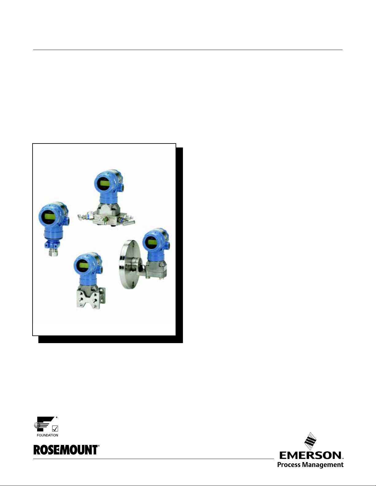
Rosemount 2051 Pressure Transmitter
with FOUNDATION™ Fieldbus Protocol
www.rosemount.com
Page 2

Page 3

Reference Manual
00809-0200-4101, Rev AA
July 2008
Rosemount 2051
Rosemount 2051 Pressure
Transmitter with F
OUNDATION
Fieldbus
NOTICE
Read this manual before working with the product. For personal and system safety, and for
optimum product performance, make sure you thoroughly understand the contents before
installing, using, or maintaining this product.
For technical assistance, contacts are listed below:
Customer Central
Technical support, quoting, and order-related questions.
United States - 1-800-999-9307 (7:00 am to 7:00 pm CST)
Asia Pacific- 65 777 8211
Europe/ Middle East/ Africa - 49 (8153) 9390
North American Response Center
Equipment service needs.
1-800-654-7768 (24 hours—includes Canada)
Outside of these areas, contact your local Emerson Process Management representative.
The products described in this document are NOT designed for nuclear-qualified
applications. Using non-nuclear qualified products in applications that require
nuclear-qualified hardware or products may cause inaccurate readings.
For information on Rosemount nuclear-qualified products, contact your local Emerson
Process Management Sales Representative.
.
.
.
.
.
www.rosemount.com
Page 4

Page 5

Reference Manual
00809-0200-4101, Rev AA
July 2008
Rosemount 2051
Table of Contents
SECTION 1
Introduction
SECTION 2
Installation
Using This Manual . . . . . . . . . . . . . . . . . . . . . . . . . . . . . . . . . . . . . . . 1-1
Service Support . . . . . . . . . . . . . . . . . . . . . . . . . . . . . . . . . . . . . . . . . 1-1
Models Covered . . . . . . . . . . . . . . . . . . . . . . . . . . . . . . . . . . . . . . . . . 1-2
Overview. . . . . . . . . . . . . . . . . . . . . . . . . . . . . . . . . . . . . . . . . . . . . . . 2-1
Safety Messages . . . . . . . . . . . . . . . . . . . . . . . . . . . . . . . . . . . . . . . . 2-1
Warnings . . . . . . . . . . . . . . . . . . . . . . . . . . . . . . . . . . . . . . . . . . . . 2-1
General Considerations . . . . . . . . . . . . . . . . . . . . . . . . . . . . . . . . . . . 2-2
Mechanical Considerations. . . . . . . . . . . . . . . . . . . . . . . . . . . . . . . . . 2-2
Environmental Considerations . . . . . . . . . . . . . . . . . . . . . . . . . . . . . . 2-2
Installation Procedures . . . . . . . . . . . . . . . . . . . . . . . . . . . . . . . . . . . . 2-3
Dimensional Drawings. . . . . . . . . . . . . . . . . . . . . . . . . . . . . . . . . . 2-3
Mount the Transmitter . . . . . . . . . . . . . . . . . . . . . . . . . . . . . . . . . 2-10
Impulse Piping . . . . . . . . . . . . . . . . . . . . . . . . . . . . . . . . . . . . . . . 2-15
Process Connections. . . . . . . . . . . . . . . . . . . . . . . . . . . . . . . . . . 2-17
Housing Rotation . . . . . . . . . . . . . . . . . . . . . . . . . . . . . . . . . . . . . 2-19
LCD Display. . . . . . . . . . . . . . . . . . . . . . . . . . . . . . . . . . . . . . . . . 2-20
Tagging . . . . . . . . . . . . . . . . . . . . . . . . . . . . . . . . . . . . . . . . . . . . 2-20
Electrical Considerations . . . . . . . . . . . . . . . . . . . . . . . . . . . . . . . . . 2-21
Conduit Installation . . . . . . . . . . . . . . . . . . . . . . . . . . . . . . . . . . 2-21
Wiring . . . . . . . . . . . . . . . . . . . . . . . . . . . . . . . . . . . . . . . . . . . . . 2-22
Transient Protection Terminal Block . . . . . . . . . . . . . . . . . . . . . . 2-23
Jumpers. . . . . . . . . . . . . . . . . . . . . . . . . . . . . . . . . . . . . . . . . . . . 2-24
Grounding . . . . . . . . . . . . . . . . . . . . . . . . . . . . . . . . . . . . . . . . . . 2-25
Hazardous Locations Certifications . . . . . . . . . . . . . . . . . . . . . . . . . 2-27
Rosemount 305, 306 and 304 Manifolds . . . . . . . . . . . . . . . . . . . . . 2-27
Rosemount 305 Integral Manifold Installation Procedure . . . . . . 2-28
Rosemount 306 Integral Manifold Installation Procedure . . . . . . 2-28
Rosemount 304 Conventional Manifold Installation Procedure. . 2-28
Integral Manifold Operation . . . . . . . . . . . . . . . . . . . . . . . . . . . . . 2-29
Liquid Level Measurement . . . . . . . . . . . . . . . . . . . . . . . . . . . . . . . . 2-31
Open Vessels . . . . . . . . . . . . . . . . . . . . . . . . . . . . . . . . . . . . . . . 2-31
Closed Vessels . . . . . . . . . . . . . . . . . . . . . . . . . . . . . . . . . . . . . . 2-31
SECTION 3
Configuration
Overview. . . . . . . . . . . . . . . . . . . . . . . . . . . . . . . . . . . . . . . . . . . . . . . 3-1
Safety Messages . . . . . . . . . . . . . . . . . . . . . . . . . . . . . . . . . . . . . . . . 3-1
Warnings . . . . . . . . . . . . . . . . . . . . . . . . . . . . . . . . . . . . . . . . . . . . 3-1
Device Capabilities . . . . . . . . . . . . . . . . . . . . . . . . . . . . . . . . . . . . . . . 3-2
Link Active Scheduler . . . . . . . . . . . . . . . . . . . . . . . . . . . . . . . . . . 3-2
Capabilities . . . . . . . . . . . . . . . . . . . . . . . . . . . . . . . . . . . . . . . . . . 3-2
General Block Information . . . . . . . . . . . . . . . . . . . . . . . . . . . . . . . . . 3-2
Modes . . . . . . . . . . . . . . . . . . . . . . . . . . . . . . . . . . . . . . . . . . . . . . 3-2
Simulation . . . . . . . . . . . . . . . . . . . . . . . . . . . . . . . . . . . . . . . . . . . 3-3
Resource Block. . . . . . . . . . . . . . . . . . . . . . . . . . . . . . . . . . . . . . . . . . 3-3
FEATURES and FEATURES_SEL . . . . . . . . . . . . . . . . . . . . . . . . 3-3
MAX_NOTIFY . . . . . . . . . . . . . . . . . . . . . . . . . . . . . . . . . . . . . . . . 3-4
Analog Input (AI) Function Block . . . . . . . . . . . . . . . . . . . . . . . . . . . . 3-5
TOC-1
Page 6

Reference Manual
00809-0200-4101, Rev AA
July 2008
Rosemount 2051
Configure the AI block . . . . . . . . . . . . . . . . . . . . . . . . . . . . . . . . . . 3-5
Configuration Examples . . . . . . . . . . . . . . . . . . . . . . . . . . . . . . . . 3-6
Pressure transmitter . . . . . . . . . . . . . . . . . . . . . . . . . . . . . . . . . . . 3-6
Pressure transmitter used to measure level in an open tank . . . . 3-6
Differential pressure transmitter to measure flow . . . . . . . . . . . . . 3-8
Filtering . . . . . . . . . . . . . . . . . . . . . . . . . . . . . . . . . . . . . . . . . . . . . 3-9
Low Cutoff . . . . . . . . . . . . . . . . . . . . . . . . . . . . . . . . . . . . . . . . . . . 3-9
Process Alarms . . . . . . . . . . . . . . . . . . . . . . . . . . . . . . . . . . . . . . 3-10
Alarm Priority . . . . . . . . . . . . . . . . . . . . . . . . . . . . . . . . . . . . . . . . 3-10
Status Options . . . . . . . . . . . . . . . . . . . . . . . . . . . . . . . . . . . . . . . 3-10
Advanced Features . . . . . . . . . . . . . . . . . . . . . . . . . . . . . . . . . . . 3-11
LCD Block. . . . . . . . . . . . . . . . . . . . . . . . . . . . . . . . . . . . . . . . . . . . . 3-11
SECTION 4
Operation and
Maintenance
SECTION 5
Troubleshooting
Overview. . . . . . . . . . . . . . . . . . . . . . . . . . . . . . . . . . . . . . . . . . . . . . . 4-1
Safety Messages . . . . . . . . . . . . . . . . . . . . . . . . . . . . . . . . . . . . . . . . 4-1
Warnings . . . . . . . . . . . . . . . . . . . . . . . . . . . . . . . . . . . . . . . . . . 4-1
Status . . . . . . . . . . . . . . . . . . . . . . . . . . . . . . . . . . . . . . . . . . . . . . . . . 4-2
Master Reset Method . . . . . . . . . . . . . . . . . . . . . . . . . . . . . . . . . . 4-2
Simulation . . . . . . . . . . . . . . . . . . . . . . . . . . . . . . . . . . . . . . . . . . . 4-2
Calibration. . . . . . . . . . . . . . . . . . . . . . . . . . . . . . . . . . . . . . . . . . . . . . 4-3
Sensor Calibration, Upper and Lower Trim Methods . . . . . . . . . . 4-3
Sensor Calibration, Zero Trim Method . . . . . . . . . . . . . . . . . . . . . 4-4
Factory Calibration Method . . . . . . . . . . . . . . . . . . . . . . . . . . . . . . 4-4
Overview. . . . . . . . . . . . . . . . . . . . . . . . . . . . . . . . . . . . . . . . . . . . . . . 5-1
Safety Messages . . . . . . . . . . . . . . . . . . . . . . . . . . . . . . . . . . . . . . . . 5-1
Warnings . . . . . . . . . . . . . . . . . . . . . . . . . . . . . . . . . . . . . . . . . . . . 5-1
Troubleshooting Guides . . . . . . . . . . . . . . . . . . . . . . . . . . . . . . . . . . . 5-2
Resource Block. . . . . . . . . . . . . . . . . . . . . . . . . . . . . . . . . . . . . . . . . . 5-5
Sensor Transducer Block . . . . . . . . . . . . . . . . . . . . . . . . . . . . . . . . . . 5-6
Analog Input (AI) Function Block . . . . . . . . . . . . . . . . . . . . . . . . . . . . 5-7
LCD Transducer block . . . . . . . . . . . . . . . . . . . . . . . . . . . . . . . . . . . . 5-7
Disassembly Procedures . . . . . . . . . . . . . . . . . . . . . . . . . . . . . . . . . . 5-9
Remove from Service . . . . . . . . . . . . . . . . . . . . . . . . . . . . . . . . . . 5-9
Remove Terminal Block . . . . . . . . . . . . . . . . . . . . . . . . . . . . . . . . 5-9
Remove the Electronics Board . . . . . . . . . . . . . . . . . . . . . . . . . . 5-10
Remove the Sensor Module from the Electronics Housing . . . . . 5-10
Reassembly Procedures. . . . . . . . . . . . . . . . . . . . . . . . . . . . . . . . . . 5-11
Attach the Electronics Board . . . . . . . . . . . . . . . . . . . . . . . . . . . . 5-11
Install the Terminal Block . . . . . . . . . . . . . . . . . . . . . . . . . . . . . . 5-11
Reassemble the 2051C Process Flange . . . . . . . . . . . . . . . . . . . 5-11
Install the Drain/Vent Valve . . . . . . . . . . . . . . . . . . . . . . . . . . . . . 5-12
APPENDIX A
Reference Data
Performance Specifications . . . . . . . . . . . . . . . . . . . . . . . . . . . . . . . . A-1
Conformance To Specification (±3s (Sigma)) . . . . . . . . . . . . . . . . A-1
Reference Accuracy . . . . . . . . . . . . . . . . . . . . . . . . . . . . . . . . . . . A-1
Long Term Stability . . . . . . . . . . . . . . . . . . . . . . . . . . . . . . . . . . . . A-2
Dynamic Performance . . . . . . . . . . . . . . . . . . . . . . . . . . . . . . . . . . A-2
Line Pressure Effect per 1000 psi (6,9 MPa). . . . . . . . . . . . . . . . . A-2
Ambient Temperature Effect per 50°F (28°C) . . . . . . . . . . . . . . . . A-3
Mounting Position Effects . . . . . . . . . . . . . . . . . . . . . . . . . . . . . . . A-3
TOC-2
Page 7

Reference Manual
00809-0200-4101, Rev AA
July 2008
Rosemount 2051
Vibration Effect . . . . . . . . . . . . . . . . . . . . . . . . . . . . . . . . . . . . . . . A-3
Power Supply Effect . . . . . . . . . . . . . . . . . . . . . . . . . . . . . . . . . . . A-3
Electromagnetic Compatibility (EMC) . . . . . . . . . . . . . . . . . . . . . . A-3
Transient Protection (Option Code T1) . . . . . . . . . . . . . . . . . . . . . A-3
Functional Specifications . . . . . . . . . . . . . . . . . . . . . . . . . . . . . . . . . . A-4
Range and Sensor Limits . . . . . . . . . . . . . . . . . . . . . . . . . . . . . . . A-4
Service. . . . . . . . . . . . . . . . . . . . . . . . . . . . . . . . . . . . . . . . . . . . . . A-4
Protocols . . . . . . . . . . . . . . . . . . . . . . . . . . . . . . . . . . . . . . . . . . . . A-4
Overpressure Limits . . . . . . . . . . . . . . . . . . . . . . . . . . . . . . . . . . . A-6
Static Pressure Limit . . . . . . . . . . . . . . . . . . . . . . . . . . . . . . . . . . . A-7
Burst Pressure Limits . . . . . . . . . . . . . . . . . . . . . . . . . . . . . . . . . . A-7
Temperature Limits . . . . . . . . . . . . . . . . . . . . . . . . . . . . . . . . . . . . A-7
Humidity Limits . . . . . . . . . . . . . . . . . . . . . . . . . . . . . . . . . . . . . . . A-8
Volumetric Displacement. . . . . . . . . . . . . . . . . . . . . . . . . . . . . . . . A-8
Damping . . . . . . . . . . . . . . . . . . . . . . . . . . . . . . . . . . . . . . . . . . . . A-8
Failure Mode Alarm . . . . . . . . . . . . . . . . . . . . . . . . . . . . . . . . . . . . A-8
Physical Specifications . . . . . . . . . . . . . . . . . . . . . . . . . . . . . . . . . . . . A-9
Electrical Connections . . . . . . . . . . . . . . . . . . . . . . . . . . . . . . . . . . A-9
Process Connections. . . . . . . . . . . . . . . . . . . . . . . . . . . . . . . . . . . A-9
2051C Process Wetted Parts . . . . . . . . . . . . . . . . . . . . . . . . . . . . A-9
2051T Process Wetted Parts. . . . . . . . . . . . . . . . . . . . . . . . . . . . . A-9
2051L Process Wetted Parts. . . . . . . . . . . . . . . . . . . . . . . . . . . . . A-9
Non-Wetted Parts for 2051C/T/L . . . . . . . . . . . . . . . . . . . . . . . . . A-10
Shipping Weights. . . . . . . . . . . . . . . . . . . . . . . . . . . . . . . . . . . . . A-11
Ordering Information. . . . . . . . . . . . . . . . . . . . . . . . . . . . . . . . . . . . . A-12
Options . . . . . . . . . . . . . . . . . . . . . . . . . . . . . . . . . . . . . . . . . . . . . . . A-22
Spare Parts. . . . . . . . . . . . . . . . . . . . . . . . . . . . . . . . . . . . . . . . . . . . A-25
APPENDIX B
Approval
Information
APPENDIX C
Block Information
Overview. . . . . . . . . . . . . . . . . . . . . . . . . . . . . . . . . . . . . . . . . . . . . . . B-1
Safety Messages . . . . . . . . . . . . . . . . . . . . . . . . . . . . . . . . . . . . . . . . B-1
Warnings . . . . . . . . . . . . . . . . . . . . . . . . . . . . . . . . . . . . . . . . . . . . B-1
Approved Manufacturing Locations . . . . . . . . . . . . . . . . . . . . . . . . B-1
European Directive Information . . . . . . . . . . . . . . . . . . . . . . . . . . . B-2
Fieldbus Protocol . . . . . . . . . . . . . . . . . . . . . . . . . . . . . . . . . . . . . . . . B-2
Hazardous Locations Certifications . . . . . . . . . . . . . . . . . . . . . . . . B-2
Approval Drawings . . . . . . . . . . . . . . . . . . . . . . . . . . . . . . . . . . . . . . . B-8
Factory Mutual (FM) . . . . . . . . . . . . . . . . . . . . . . . . . . . . . . . . . . . B-8
Canadian Standards Association (CSA) . . . . . . . . . . . . . . . . . . . B-21
Transducer Block . . . . . . . . . . . . . . . . . . . . . . . . . . . . . . . . . . . . . . . . C-1
Overview . . . . . . . . . . . . . . . . . . . . . . . . . . . . . . . . . . . . . . . . . . . . C-1
Parameters and Descriptions . . . . . . . . . . . . . . . . . . . . . . . . . . . . C-2
Block/Transducer Errors . . . . . . . . . . . . . . . . . . . . . . . . . . . . . . . . C-4
Troubleshooting. . . . . . . . . . . . . . . . . . . . . . . . . . . . . . . . . . . . . . . C-6
Resource Block. . . . . . . . . . . . . . . . . . . . . . . . . . . . . . . . . . . . . . . . . . C-6
Overview . . . . . . . . . . . . . . . . . . . . . . . . . . . . . . . . . . . . . . . . . . . . C-6
Parameters and Descriptions . . . . . . . . . . . . . . . . . . . . . . . . . . . . C-7
TOC-3
Page 8

Rosemount 2051
Reference Manual
00809-0200-4101, Rev AA
July 2008
TOC-4
Page 9

Reference Manual
00809-0200-4101, Rev AA
July 2008
Rosemount 2051
Section 1 Introduction
USING THIS MANUAL The sections in this manual provide information on installing, operating, and
maintaining Rosemount 2051 pressure transmitters with F
The sections are organized as follows:
• Section 2: Installation contains mechanical and electrical installation
instructions.
• Section 3: Configuration provides instruction on basic operation,
software functionality, and basic configuration procedures.
• Section 4: Operation and Maintenance contains operation and
maintenance techniques.
• Section 5: Troubleshooting contains information on the
troubleshooting suggestions for the most common operating problems.
Also included are disassembly and reassembly procedures.
• Section A: Reference Data supplies reference and specification data,
as well as ordering information.
• Section B: Approval Information contains intrinsic safety approval
information, European ATEX directive information, and
approval drawings.
• Section C: Block Information contains information on the Transducer
and Resource blocks.
OUNDATION fieldbus.
SERVICE SUPPORT To expedite the return process outside of the United States, contact the
nearest Emerson Process Management representative.
Within the United States, call the Emerson Process Management Instrument
and Valves Response Center using the 1-800-654-RSMT (7768) toll-free
number. This center, available 24 hours a day, will assist you with any needed
information or materials.
The center will ask for product model and serial numbers, and will provide a
Return Material Authorization (RMA) number. The center will also ask for the
process material to which the product was last exposed.
Individuals who handle products exposed to a hazardous substance can avoid injury if they
are informed of and understand the hazard. If the product being returned was exposed to a
hazardous substance as defined by OSHA, a copy of the required Material Safety Data Sheet
(MSDS) for each hazardous substance identified must be included with the returned goods.
Emerson Process Management Instrument and Valves Response Center
representatives will explain the additional information and procedures
necessary to return goods exposed to hazardous substances.
www.rosemount.com
Page 10

Reference Manual
00809-0200-4101, Rev AA
Rosemount 2051
July 2008
MODELS COVERED The following Rosemount 2051 Pressure Transmitters are covered by this
manual:
Rosemount 2051C Coplanar
2051CD - Differential Pressure Transmitter
Measures differential pressure up to 2000 psi (137,9 bar)
2051CG - Gage Pressure Transmitter
Measures gage pressure up to 2000 psi (137,9 bar)
Rosemount 2051T In-Line Pressure Transmitter
2051TG - Gage Pressure Transmitter
Measures gage pressure up to 10000 psi (689,5 bar)
2051TA - Absolute Pressure Transmitter
Measures absolute pressure up to 10000 psi (689,5 bar)
Rosemount 2051L Liquid Level Pressure Transmitter
2051L - Flange-Mounted Liquid Level Transmitter
Provides precise level and specific gravity measurements up to 300 psi
(20,7 bar) for a wide variety of tank configurations
™
Pressure Transmitter
1-2
Page 11

Reference Manual
00809-0200-4101, Rev AA
July 2008
Rosemount 2051
Section 2 Installation
Overview . . . . . . . . . . . . . . . . . . . . . . . . . . . . . . . . . . . . . . . page 2-1
Safety Messages . . . . . . . . . . . . . . . . . . . . . . . . . . . . . . . . . page 2-1
General Considerations . . . . . . . . . . . . . . . . . . . . . . . . . . . page 2-2
Mechanical Considerations . . . . . . . . . . . . . . . . . . . . . . . . page 2-2
Environmental Considerations . . . . . . . . . . . . . . . . . . . . . page 2-2
Installation Procedures . . . . . . . . . . . . . . . . . . . . . . . . . . . page 2-3
Dimensional Drawings . . . . . . . . . . . . . . . . . . . . . page 2-3
Electrical Considerations . . . . . . . . . . . . . . . . . . . . . . . . . . page 2-21
Hazardous Locations Certifications . . . . . . . . . . . . . . . . . page 2-27
Rosemount 305, 306 and 304 Manifolds . . . . . . . . . . . . . . page 2-27
Liquid Level Measurement . . . . . . . . . . . . . . . . . . . . . . . . . page 2-31
OVERVIEW The information in this section covers installation considerations for the
Rosemount 2051 with F
F
OUNDATION fieldbus (document number 00825-0200-4101) is shipped with
every transmitter to describe basic pipe-fitting and wiring procedures for initial
installation. Dimensional drawings for each 2051 variation and mounting
configuration are also included.
OUNDATION fieldbus. A Quick Installation Guide for
SAFETY MESSAGES Procedures and instructions in this section may require special precautions to
ensure the safety of the personnel performing the operation. Information that
raises potential safety issues is indicated with a warning symbol ( ). Refer
to the following safety messages before performing an operation preceded by
this symbol.
Warnings
Explosions could result in death or serious injury:
Installation of this transmitter in an explosive environment must be in accordance with the
appropriate local, national, and international standards, codes, and practices. Please review the
approvals section of the 2051 reference manual for any restrictions associated with a safe
installation.
• Before connecting a Field Communicator in an explosive atmosphere, ensure the
instruments in the loop are installed in accordance with intrinsically safe or non-incendive
field wiring practices.
• In an Explosion-Proof/Flameproof installation, do not remove the transmitter covers when
power is applied to the unit.
Process leaks may cause harm or result in death.
• Install and tighten process connectors before applying pressure.
Electrical shock can result in death or serious injury.
• Avoid contact with the leads and terminals. High voltage that may be present on leads can
cause electrical shock.
www.rosemount.com
Page 12

Rosemount 2051
Reference Manual
00809-0200-4101, Rev AA
July 2008
Electrical shock can result in death or serious injury.
• Avoid contact with the leads and terminals.
Process leaks could result in death or serious injury.
• Install and tighten all four flange bolts before applying pressure.
• Do not attempt to loosen or remove flange bolts while the transmitter is
in service.
Replacement equipment or spare parts not approved by Emerson Process
Management for use as spare parts could reduce the pressure retaining
capabilities of the transmitter and may render the instrument dangerous.
• Use only bolts supplied or sold by Emerson Process Management as spare
parts.
• Refer to page A-25 for a complete list of spare parts.
Improper assembly of manifolds to traditional flange can damage sensor module.
• For safe assembly of manifold to traditional flange, bolts must break back
plane of flange web (i.e., bolt hole) but must not contact sensor module
housing.
GENERAL CONSIDERATIONS
MECHANICAL CONSIDERATIONS
Measurement accuracy depends upon proper installation of the transmitter
and impulse piping. Mount the transmitter close to the process and use a
minimum of piping to achieve best accuracy. Also, consider the need for easy
access, personnel safety, practical field calibration, and a suitable transmitter
environment. Install the transmitter to minimize vibration, shock, and
temperature fluctuation.
IMPORTANT
Install the enclosed pipe plug (found in the box) in unused conduit opening
with a minimum of five threads engaged to comply with explosion-proof
requirements.
For material compatibility considerations, see document number
00816-0100-3045 on www.emersonprocess.com/rosemount.
NOTE
For steam service or for applications with process temperatures greater than
the limits of the transmitter, do not blow down impulse piping through the
transmitter. Flush lines with the blocking valves closed and refill lines with
water before resuming measurement.
NOTE
When the transmitter is mounted on its side, position the Coplanar flange to
ensure proper venting or draining. Mount the flange as shown in Figure 2-8 on
page 2-16, keeping drain/vent connections on the bottom for gas service and
on the top for liquid service.
ENVIRONMENTAL CONSIDERATIONS
2-2
Best practice is to mount the transmitter in an environment that has minimal
ambient temperature change. The transmitter electronics temperature
operating limits are –40 to 185 °F (–40 to 85 °C). Refer to Appendix A:
Reference Data that lists the sensing element operating limits. Mount the
transmitter so that it is not susceptible to vibration and mechanical shock and
does not have external contact with corrosive materials.
Page 13
Reference Manual
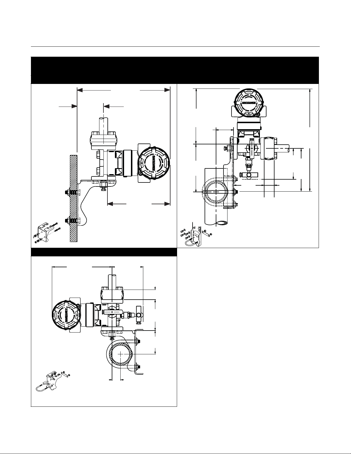
3.85 (98)
7.03 (179)
4.99 (127)
5.46 (138,7)
6.40 (163)
3.85 (98)
7.44
(189)
Drain/ Vent
Valve
5.50 (140)
MAX OPEN
6.19
(157)
10.60 (270)
MAX OPEN
4.99 (127)
5.46 (138,7)
00809-0200-4101, Rev AA
July 2008
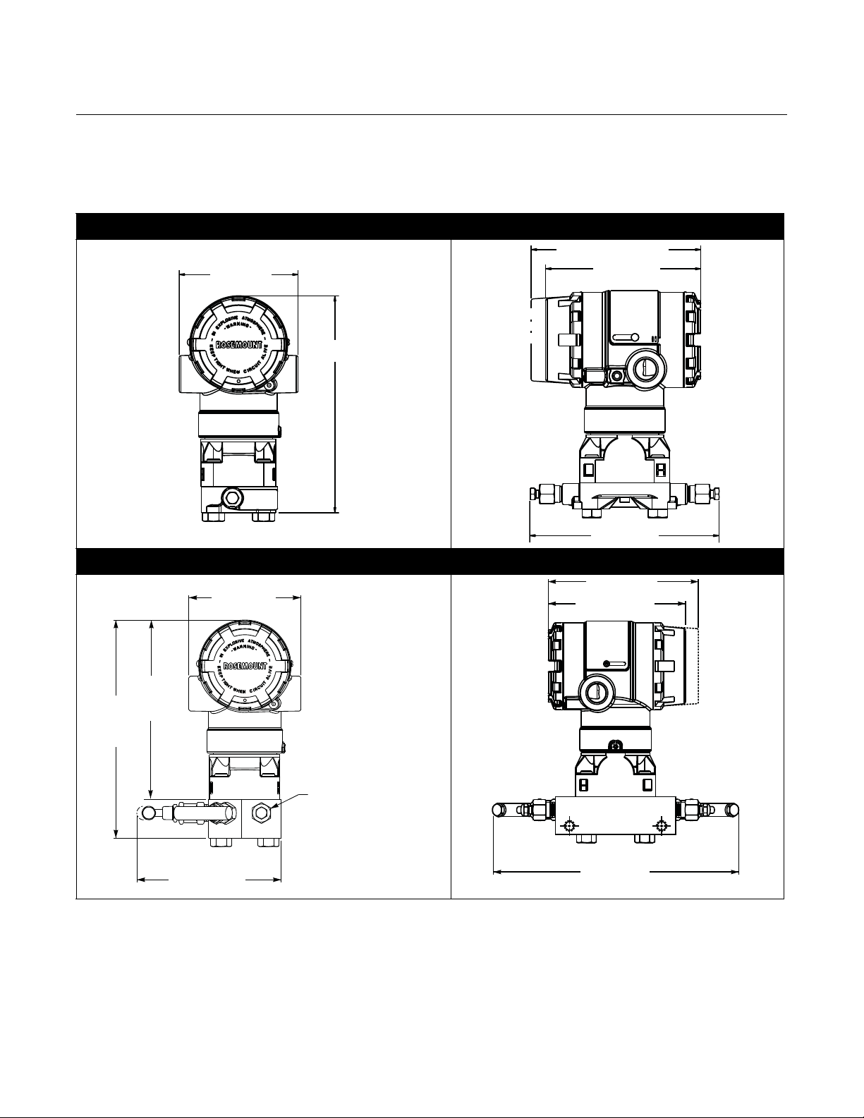
INSTALLATION PROCEDURES
Dimensional Drawings
Rosemount 2051
2051C Coplanar Flange Dimensional Drawing
2051C Coplanar with Rosemount 305 Coplanar Integral Manifold
2-3
Page 14
Rosemount 2051
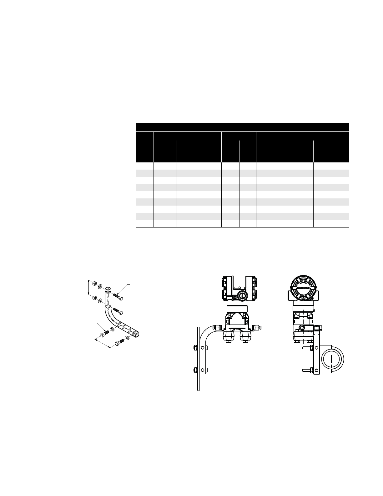
4.99 (127)
7.03
(179)
2.81
(71)
4.73
(120)
6.15
(156)
2.45 (62)
5
/16 ⫻ 11/2 Bolts
for Panel Mounting
(Not Supplied)
3
/8–16 × 11/4 Bolts
for Mounting
to Transmitter
2.8 (71)
3.4 (85)
6.22
(158)
3.51
(89)
2-inch U-Bolt
for Pipe Mounting
3.4 (85)
3
/8–16 × 11/4 Bolts
for Mounting
to Transmitter
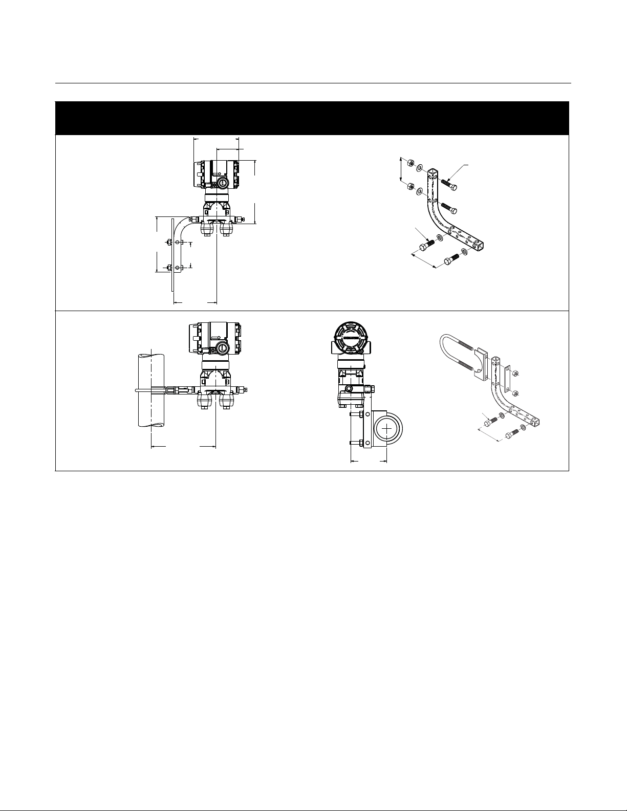
Coplanar Flange Mounting Configurations with
Optional Bracket (B4) for 2-in. Pipe or Panel Mounting
PANEL MOUNTINGPIPE MOUNTING
Reference Manual
00809-0200-4101, Rev AA
July 2008
Dimensions are in inches (millimeters)
2-4
Page 15
Reference Manual
3.85 (98)
7.76
(197)
3.40 (86)
1.10 (28)
1
/2 - 14 NPT
Flange
Adapter
(optional)
Drain/
Vent Val ve
5.46 (139)
4.99 (127)
1.626
(41,3)
2.126
(54)
3.85 (98)
1
/2 - 14 NPT
Flange
Adapter
(optional)
Drain/
Vent Val ve
3.50
(89)
1.05
(27)
1.10
(28)
3.75 (95)
MAX OPEN
6.19
(157)
2.126
(54)
6.20 (158)
MAX
OPEN
8.90 (226)
MAX OPEN
2.70 (69)
MAX
OPEN
1.626
(41,3)
5.46 (139)
4.99 (127)
00809-0200-4101, Rev AA
July 2008
Rosemount 2051
2051C Coplanar with Traditional Flange
2051C Coplanar with Rosemount 305 Traditional Integral Manifold
2-5
Page 16
Rosemount 2051
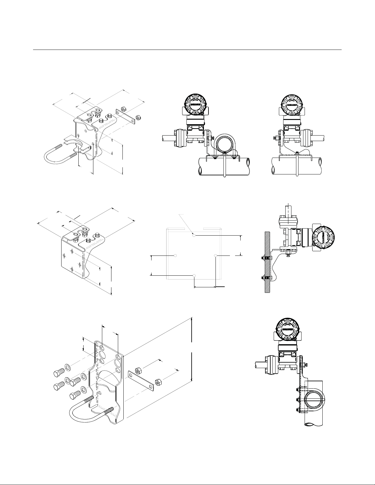
9.18 (233)
2.62
(67)
6.19 (157)
5.32
(135)
1.94
(49)
3.50
(89)
1.10
(28)
3.56
(90)
4.85
(123)
6.19
(157)
11.51
(292)
6.76 (172)
3.56 (90)
MAX OPEN
1.10 (28)
3.50 (89)
2.62 (67)
0.93
(24)
Traditional Flange Mounting Configurations with
Optional Brackets for 2-in. Pipe or Panel Mounting
Panel Mount (Bracket Option B2 / B8) Pipe Mount (Bracket Option B3 / B9 / BC)
Reference Manual
00809-0200-4101, Rev AA
July 2008
Pipe Mount (Bracket Option B1 / B7 / BA)
2-6
Page 17
Reference Manual
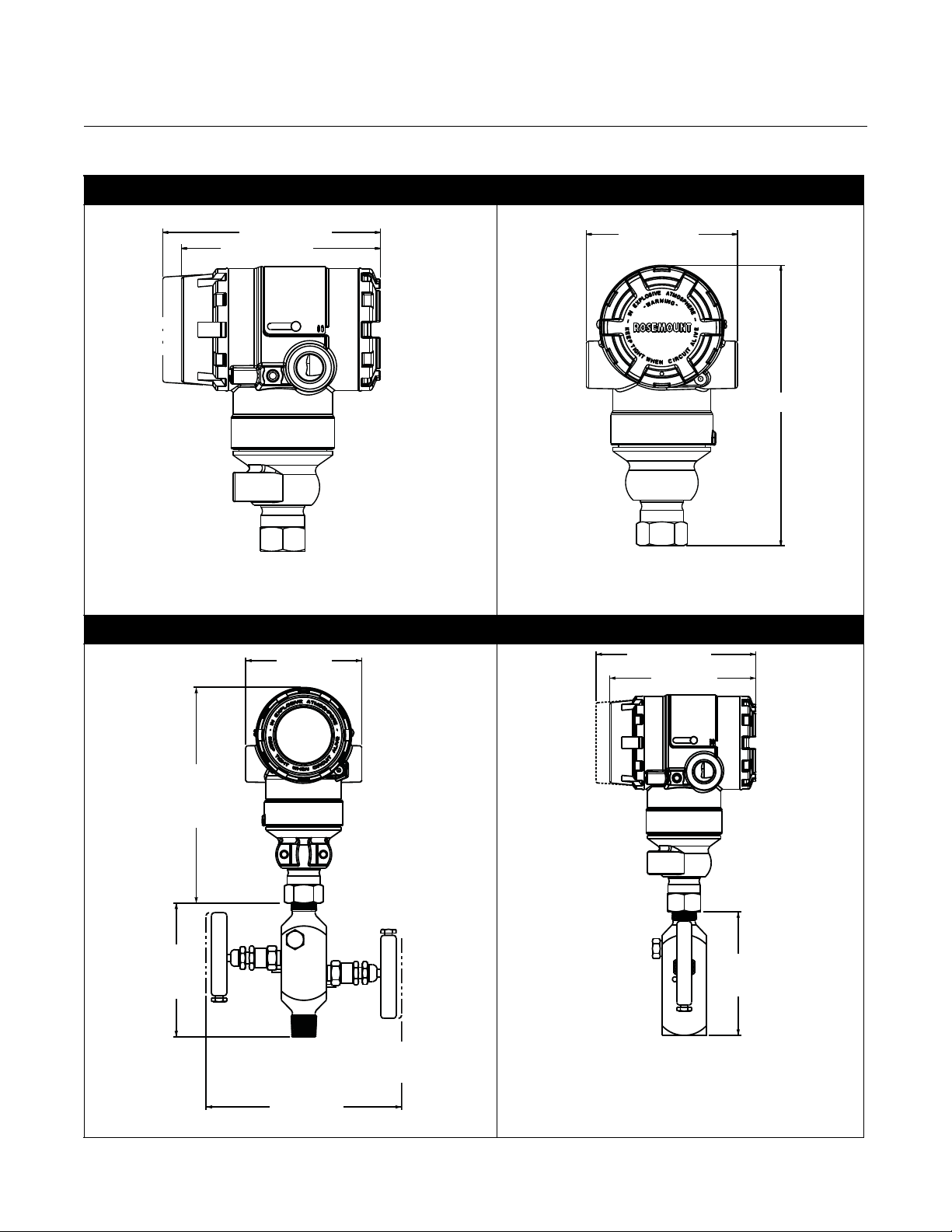
5.46 (139)
4.99 (127)
3.85 (98)
7.15 (182)
3.85 (98)
7.15
(182)
4.85
(123)
6.25
(159)
MAX OPEN
4.99 (127)
4.10
(105)
5.46 (139)
00809-0200-4101, Rev AA
July 2008
Rosemount 2051
2051T Dimensional Drawings
2051T with Rosemount 306 Integral Manifold
2-7
Page 18
Rosemount 2051
6.21
(158)
3.49
(89)
3.85
(98)
1.99 (51)
4.72
(120)
6.90
(175)
2.81 (71)
5.16 (131)
2051T Typical Mounting Configurations with Optional Mounting Bracket
Pipe Mounting Panel Mounting
Reference Manual
00809-0200-4101, Rev AA
July 2008
2-8
Page 19
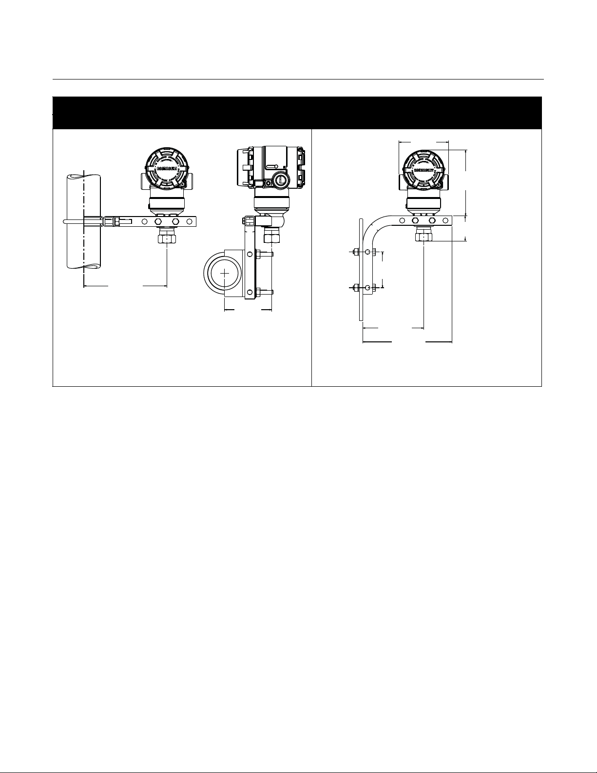
Reference Manual
3.85
(98)
A
H
3.85
(98)
D
A
H
2-in., 4-in., or
6-in.
Extension
(50.8, 101.6,
152.4)
E
5.46 (138,7)
4.99 (127)
6.60
(68)
7.02
(178)
8.12
(206)
Flushing Connection
E
F
G
C
B
00809-0200-4101, Rev AA
July 2008
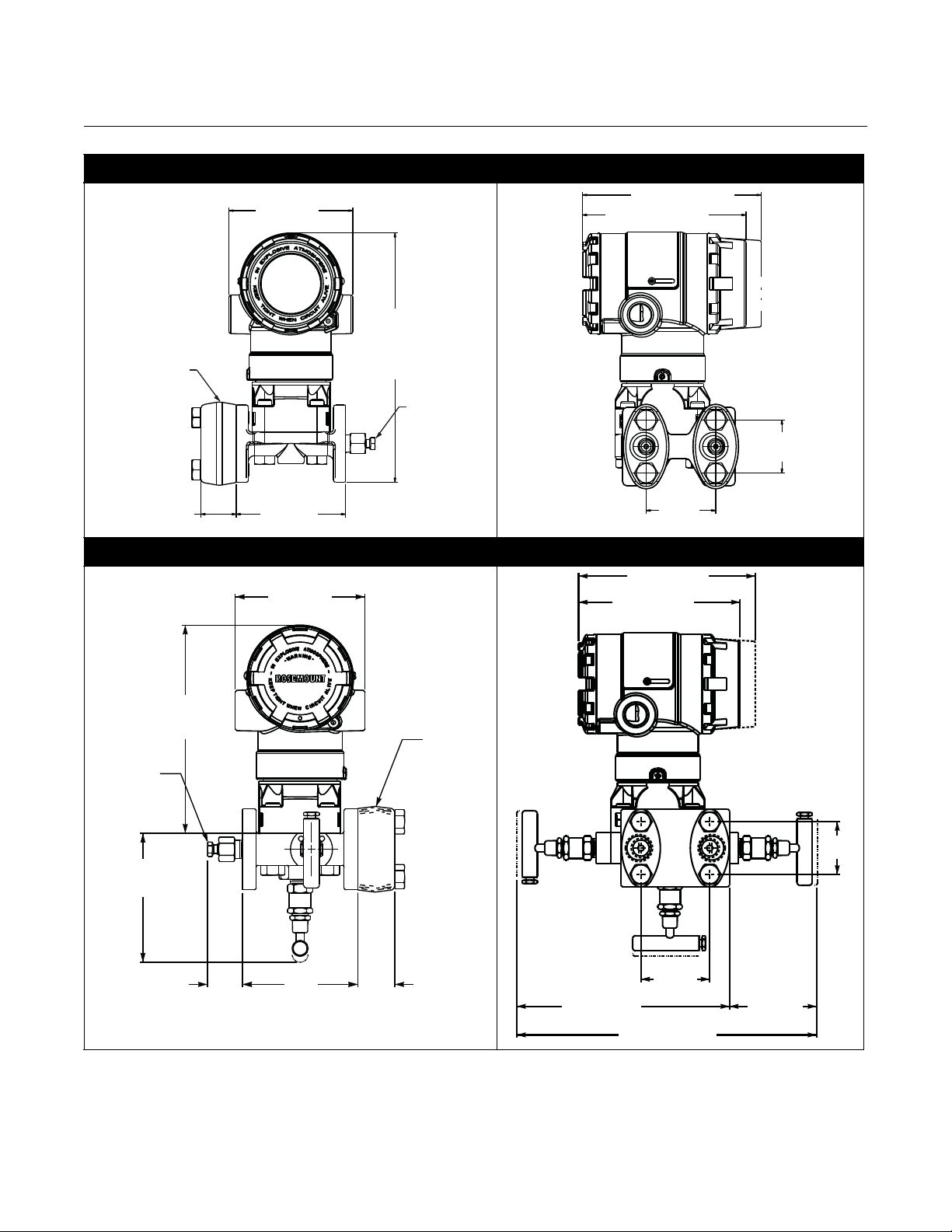
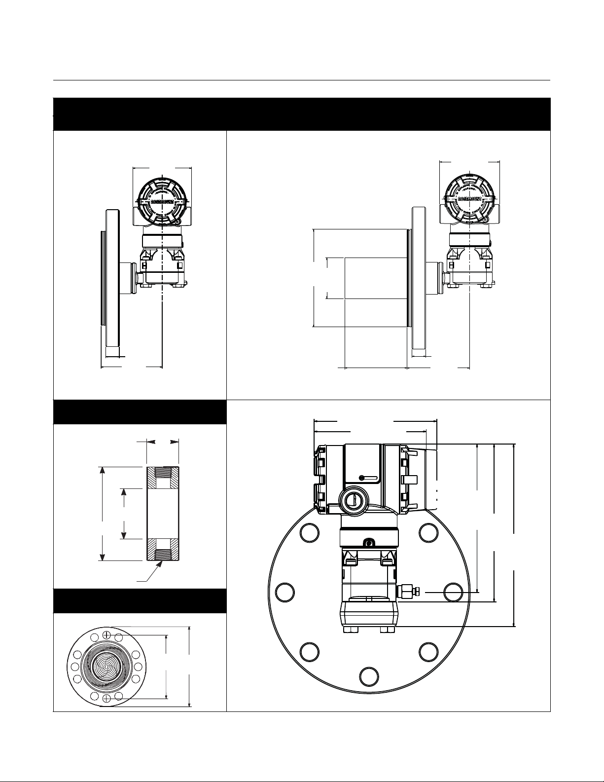
Rosemount 2051
2051L Liquid Level
2-in. Flange Configuration (Flush Mount Only) 3- and 4-in. Flange Configuration
Optional Flushing Connection Ring
(Lower Housing)
Diaphragm Assembly and
Mounting Flange
2-9
Page 20

Reference Manual
00809-0200-4101, Rev AA
(1)
D
July 2008
O.D. Gasket
Surface E
Rosemount 2051
Table 2-1. 2051L Dimensional Specifications
Except where indicated, dimensions are in inches (millimeters).
Class
ASME B16.5 (ANSI) 150 2 (51) 0.69 (18) 4.75 (121) 6.0 (152) 4 0.75 (19) NA 3.6 (92)
ASME B16.5 (ANSI) 300 2 (51) 0.82 (21) 5.0 (127) 6.5 (165) 8 0.75 (19) NA 3.6 (92)
DIN 2501 PN 10–40 DN 50 20 mm 125 mm 165 mm 4 18 mm NA 4.0 (102)
DIN 2501 PN 25/40 DN 80 24 mm 160 mm 200 mm 8 18 mm 65 mm 5.4 (138)
Pipe
Size
3 (76) 0.88 (22) 6.0 (152) 7.5 (191) 4 0.75 (19) 2.58 (66) 5.0 (127)
4 (102) 0.88 (22) 7.5 (191) 9.0 (229) 8 0.75 (19) 3.5 (89) 6.2 (158)
3 (76) 1.06 (27) 6.62 (168) 8.25 (210) 8 0.88 (22) 2.58 (66) 5.0 (127)
4 (102) 1.19 (30) 7.88 (200) 10.0 (254) 8 0.88 (22) 3.5 (89) 6.2 (158)
DN 100 24 mm 190 mm 235 mm 8 22 mm 89 mm 6.2 (158)
Flange
Thickness A
Bolt Circle
Diameter B
Outside
Diameter C
No. of
Bolts
Bolt Hole
Diameter
Extension
Diameter
(1)
Class
ASME B16.5 (ANSI) 150 2 (51) 2.12 (54) 0.97 (25) 1.31 (33) 5.65 (143)
ASME B16.5 (ANSI) 300 2 (51) 2.12 (54) 0.97 (25) 1.31 (33) 5.65 (143)
DIN 2501 PN 10–40 DN 50 2.4 (61) 0.97 (25) 1.31 (33) 5.65 (143)
DIN 2501 PN 25/40 DN 80 3.6 (91) 0.97 (25) 1.31 (33) 5.65 (143)
(1) Tolerances are -0.020 and +0.040 (-0,51 and +1,02)
Pipe
Size
3 (76) 3.6 (91) 0.97 (25) 1.31 (33) 5.65 (143)
4 (102) 3.6 (91) 0.97 (25) 1.31 (33) 5.65 (143)
3 (76) 3.6 (91) 0.97 (25) 1.31 (33) 5.65 (143)
4 (102) 3.6 (91) 0.97 (25) 1.31 (33) 5.65 (143)
DN 100 3.6 (91) 0.97 (25) 1.31 (33) 5.65 (143)
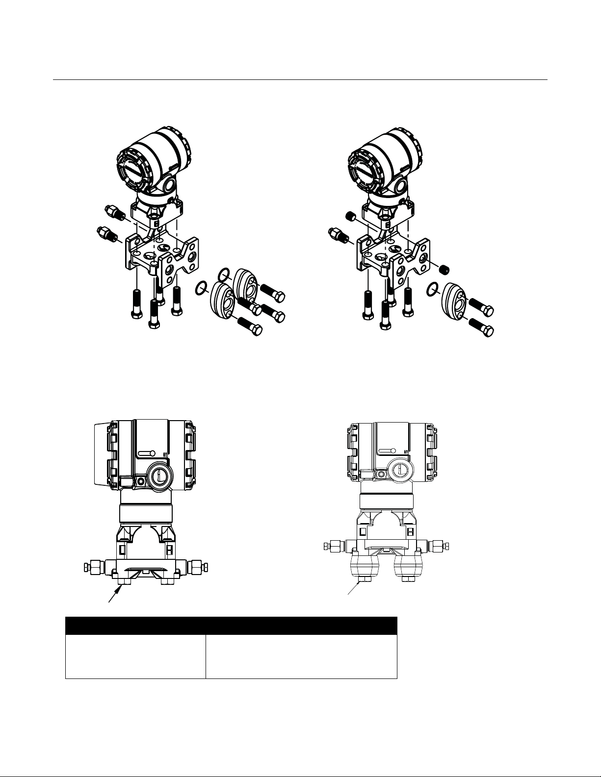
Mount the Transmitter Process Flange Orientation
Mount the process flanges with sufficient clearance for process connections.
For safety reasons, place the drain/vent valves so the process fluid is directed
away from possible human contact when the vents are used. In addition,
consider the accessibility for a testing or calibration input.
NOTE
Most transmitters are calibrated in the horizontal position. Mounting the
transmitter in any other position will shift the zero point to the equivalent
amount of liquid head pressure caused by the varied mounting position. To
reset zero point, refer to “Sensor Trim” on page 4-5.
Process
Side F
Lower Housing G
H1/4 NPT 1/2 NPT
2-10
Terminal Side of Electronics Housing
Mount the transmitter so the terminal side is accessible. Clearance of 0.75-in.
(19 mm) is required for cover removal. Use a conduit plug on the unused side
of the conduit opening.
Circuit Side of Electronics Housing
Provide 0.75 in. (19 mm) of clearance for units without an LCD display.
Provide 3 in. (76 mm) of clearance for units installed with LCD.
Cover Installation
Always ensure a proper seal by installing the electronics housing covers so
that metal contacts metal. Use Rosemount o-rings.
Page 21
Reference Manual
5
/16 3 11/2 Bolts
for Panel Mounting
(Not Supplied)
3
/8–16 × 11/4 Bolts
for Mounting
to Transmitter
2.8 (71)
3.4 (85)
00809-0200-4101, Rev AA
July 2008
Table 2-2. Mounting Brackets
Rosemount 2051
Mounting Brackets
Rosemount 2051 Transmitters may be panel-mounted or pipe-mounted
through an optional mounting bracket. Refer to Table 2-2 for the complete
offering and see Figure 2-1 through Figure 2-5 on pages 2-11 and 2-12 for
dimensions and mounting configurations.
2051 Brackets
Process Connections Mounting Materials
Flat
Option
Coplanar In-Line Traditional
Code
B4 X X X X X X X
B1 X X X X
B2 X X X X
B3 X X X X
B7 X X X X
B8 X X X X
B9 X X X X
BA X X X X
BC X X X X
Pipe
Mount
Panel
Mount
Panel
Mount
CS
Bracket
SST
Bracket
CS
Bolts
SST
Bolts
Figure 2-1. Mounting Bracket Option Code B4
2-11
Page 22
Rosemount 2051
3.87 (98)
3.75 (95)
1.65 (42)
2.62 (67)
4.97
(127)
2.81
(71)
1.65 (42)
3.87 (98)
4.5 (114)
1.40 (36)
Mounting Holes
0.375 Diameter
(10)
3.75 (95)
2.81
(71)
2.125 (54)
2.81 (71)
8 (203)
NOTE
Dimensions are in inches (millimeters).
1.62 (41)
Figure 2-2. Mounting Bracket Option Codes B1, B7, and BA
1.40
(36)
1.40
(36)
Figure 2-4. Panel Mounting Bracket Option Codes B2 and B8
Figure 2-5. Flat Mounting Bracket Option Codes B3 and BC
Reference Manual
00809-0200-4101, Rev AA
July 2008
2-12
Page 23
Reference Manual
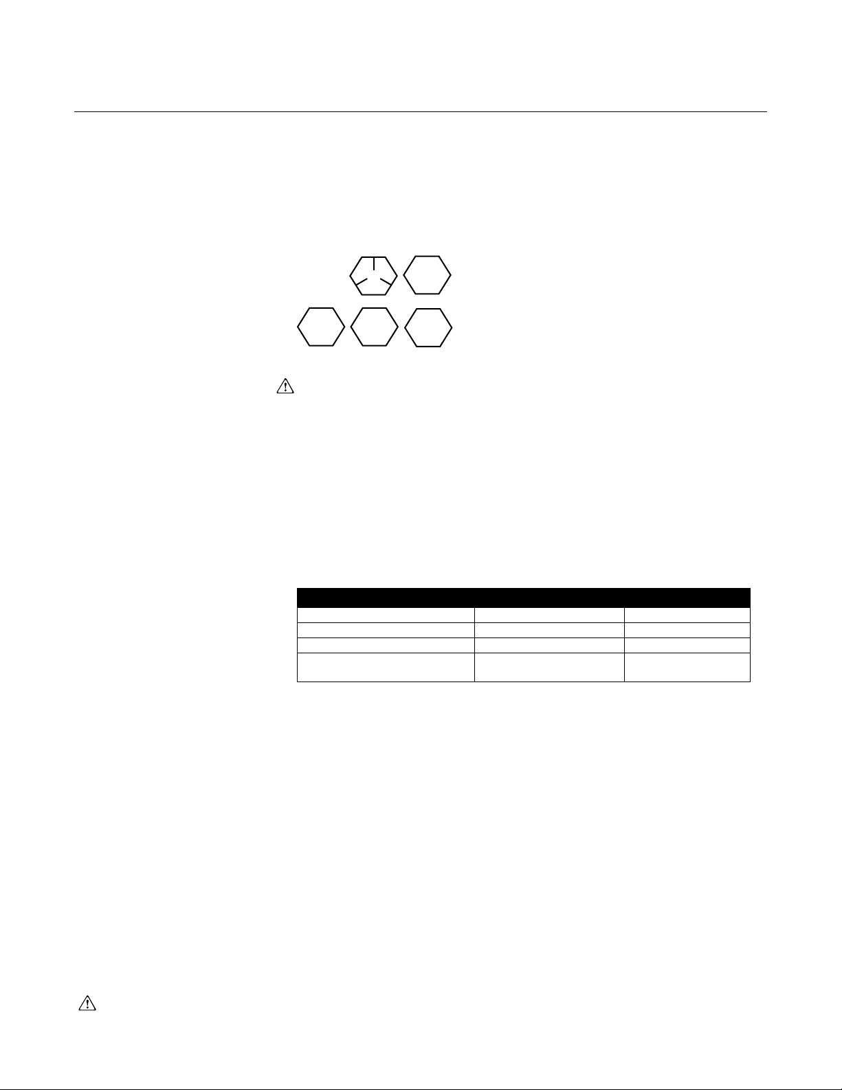
Carbon Steel (CS) Head Markings
B7M
B8M
F593_*
Stainless Steel (SST) Head Markings
* The last digit in the F593_ head marking
may be any letter between A and M.
316
See “Safety Messages” on page 2-1 for complete warning information.
00809-0200-4101, Rev AA
July 2008
Rosemount 2051
Flange Bolts
The 2051 is shipped with a Coplanar flange installed with four 1.75-in. (44
mm) flange bolts. See Figure 2-6 and Figure 2-7 on pages 2-14 and 2-14.
Stainless steel bolts are coated with a lubricant to ease installation. Carbon
steel bolts do not require lubrication. No additional lubricant should be applied
when installing either type of bolt. Bolts are identified by their head markings:
Bolt Installation
Only use bolts supplied with the 2051 or provided by Emerson Process
Management as spare parts. When installing the transmitter to one of the
optional mounting brackets, torque the bolts to 125 in-lb. (0,9 N-m). Use
the following bolt installation procedure:
Table 2-3. Bolt Installation
Torque Values
1. Finger-tighten the bolts.
2. Torque the bolts to the initial torque value using a crossing pattern.
3. Torque the bolts to the final torque value using the same
crossing pattern.
Torque values for the flange and manifold adapter bolts are as follows:
Bolt Material Initial Torque Value Final Torque Value
CS-ASTM-A449 Standard 300 in.-lb (34 N-m) 650 in.-lb (73 N-m)
316 SST—Option L4 150 in.-lb (17 N-m) 300 in.-lb (34 N-m)
ASTM-A-193-B7M—Option L5 300 in.-lb (34 N-m) 650 in.-lb (73 N-m)
ASTM-A-193 Class 2, Grade
B8M—Option L8
150 in.-lb (17 N-m) 300 in.-lb (34 N-m)
2-13
Page 24
Rosemount 2051
GAGE TRANSMITTERDIFFERENTIAL TRANSMITTER
Drain/Vent
Drain/Vent
Plug
1.75 (44) × 4
1.50 (38) × 4
1.75 (44) × 4
1.50 (38) × 2
NOTE
Dimensions are in inches (millimeters).
Drain/Vent
TRANSMITTER WITH
FLANGE BOLTS
TRANSMITTER WITH
FLANGE ADAPTERS AND
FLANGE/ADAPTER BOLTS
Description Size in. (mm)
Flange Bolts 1.75 (44)
Flange/Adapter Bolts 2.88 (73)
Manifold/Flange Bolts 2.25 (57)
Note: Rosemount 2051T transmitters are direct mount and do not require bolts for process connection.
NOTE
Dimensions are in inches (millimeters).
1.75 (44) × 4
2.88 (73) × 4
Figure 2-6. Traditional Flange Bolt Configurations
Reference Manual
00809-0200-4101, Rev AA
July 2008
Figure 2-7. Mounting Bolts and Bolt Configurations for Coplanar Flange
2-14
Page 25

Reference Manual
00809-0200-4101, Rev AA
July 2008
Rosemount 2051
Impulse Piping The piping between the process and the transmitter must accurately transfer
the pressure to obtain accurate measurements. There are six possible
sources of impulse piping error: pressure transfer, leaks, friction loss
(particularly if purging is used), trapped gas in a liquid line, liquid in a gas line,
and density variations between the legs.
The best location for the transmitter in relation to the process pipe is
dependent on the process. Use the following guidelines to determine
transmitter location and placement of impulse piping:
• Keep impulse piping as short as possible.
• For liquid service, slope the impulse piping at least 1 in./foot (8 cm/m)
upward from the transmitter toward the process connection.
• For gas service, slope the impulse piping at least 1 in./foot (8 cm/m)
downward from the transmitter toward the process connection.
• Avoid high points in liquid lines and low points in gas lines.
• Make sure both impulse legs are the same temperature.
• Use impulse piping large enough to avoid friction effects and blockage.
• Vent all gas from liquid piping legs.
• When using a sealing fluid, fill both piping legs to the same level.
• When purging, make the purge connection close to the process taps
and purge through equal lengths of the same size pipe. Avoid purging
through the transmitter.
• Keep corrosive or hot (above 250 °F [121 °C]) process material out of
direct contact with the sensor module and flanges.
• Prevent sediment deposits in the impulse piping.
• Maintain equal leg of head pressure on both legs of the impulse piping.
• Avoid conditions that might allow process fluid to freeze within the
process flange.
2-15
Page 26
Rosemount 2051
LIQUID SERVICE GAS SERVICE STEAM SERVICE
F
lo
w
F
lo
w
F
lo
w
Reference Manual
00809-0200-4101, Rev AA
July 2008
Mounting Requirements
Impulse piping configurations depend on specific measurement conditions.
Refer to Figure 2-8 for examples of the following mounting configurations:
Liquid Flow Measurement
• Place taps to the side of the line to prevent sediment deposits on the
process isolators.
• Mount the transmitter beside or below the taps so gases vent into the
process line.
• Mount drain/vent valve upward to allow gases to vent.
Gas Flow Measurement
• Place taps in the top or side of the line.
• Mount the transmitter beside or above the taps so to drain liquid into
the process line.
Steam Flow Measurement
• Place taps to the side of the line.
• Mount the transmitter below the taps to ensure that impulse piping will
remain filled with condensate.
• In steam service above 250 °F (121 °C), fill impulse lines with water to
prevent steam from contacting the transmitter directly and to ensure
accurate measurement start-up.
NOTE
For steam or other elevated temperature services, it is important that
temperatures at the process connection do not exceed the transmitter’s
process temperature limits. See “Process Temperature Limits” on page A-7
for details.
Figure 2-8. Installation
Examples
2-16
Page 27

Reference Manual
00809-0200-4101, Rev AA
July 2008
Process Connections Coplanar or Traditional Process Connection
Install and tighten all four flange bolts before applying pressure, or process
leakage will result. When properly installed, the flange bolts will protrude
through the top of the sensor module housing. Do not attempt to loosen or
remove the flange bolts while the transmitter is in service.
Flange Adaptors:
Rosemount 2051DP and GP process connections on the transmitter flanges
1
are
/4–18 NPT. Flange adapters are available with standard 1/2–14 NPT Class
2 connections. The flange adapters allow users to disconnect from the
process by removing the flange adapter bolts. Use plant-approved lubricant or
sealant when making the process connections. Refer to Dimensional
Drawings on page 2-3 for the distance between pressure connections. This
distance may be varied ±
adapters.
To install adapters to a Coplanar flange, perform the following procedure:
1. Remove the flange bolts.
2. Leaving the flange in place, move the adapters into position with the
o-ring installed.
3. Clamp the adapters and the Coplanar flange to the transmitter sensor
module using the larger of the bolts supplied.
4. Tighten the bolts. Refer to “Flange Bolts” on page 2-13 for torque
specifications.
1
/8 in. (3.2 mm) by rotating one or both of the flange
Rosemount 2051
Whenever you remove flanges or adapters, visually inspect the PTFE o-rings.
Replace with o-ring designed for Rosemount transmitter if there are any signs
of damage, such as nicks or cuts. Undamaged o-rings may be reused. If you
replace the o-rings, retorque the flange bolts after installation to compensate
for cold flow. Refer to the process sensor body reassembly procedure in
Section 5: Troubleshooting.
2-17
Page 28
Rosemount 2051
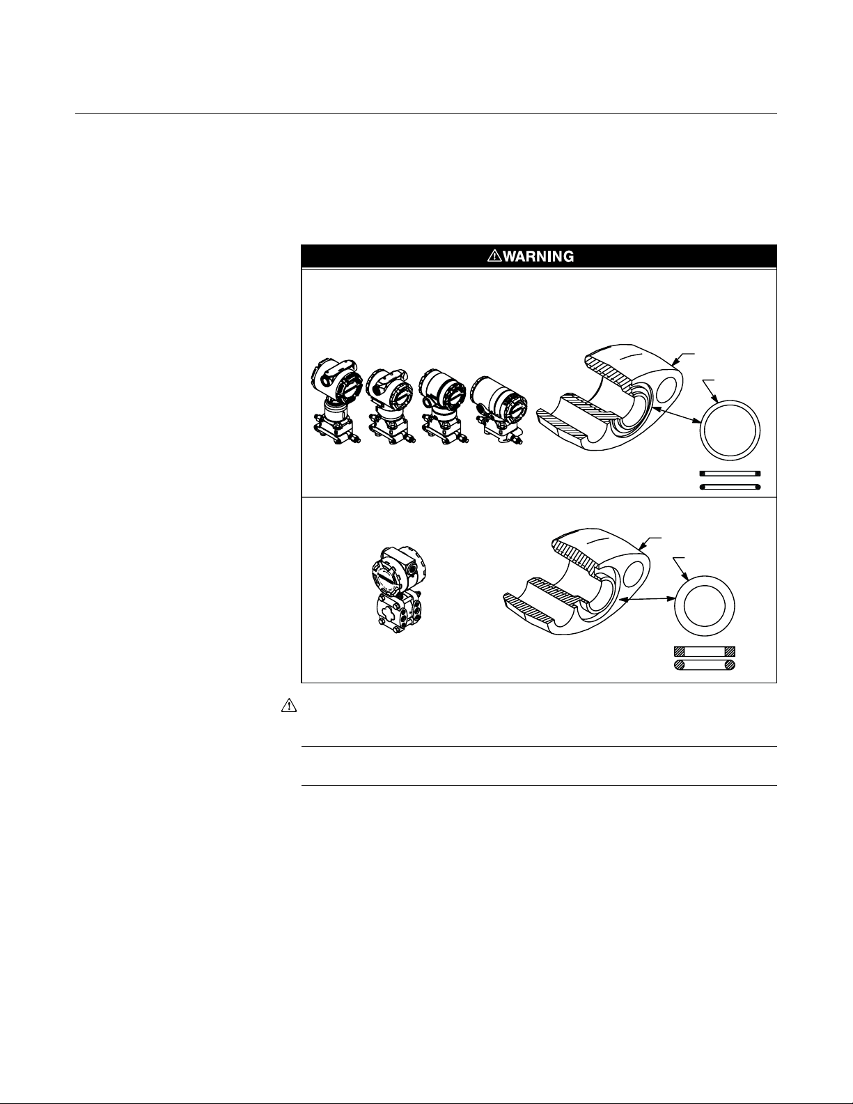
Failure to install proper flange adapter O-rings may cause process leaks, which can result in
death or serious injury. The two flange adapters are distinguished by unique O-ring grooves.
Only use the O-ring that is designed for its specific flange adapter, as shown below.
ROSEMOUNT 3051S / 3051 / 2051 / 3001 / 3095 / 2024
ROSEMOUNT 1151
Flange
Adapter
O-ring
Flange Adapter
O-ring
PTFE Based
Elastomer
PTFE
Elastomer
Figure 2-9. O-Rings.
Reference Manual
00809-0200-4101, Rev AA
July 2008
O-rings:
The two styles of Rosemount flange adapters (Rosemount 1151 and
Rosemount 3051/2051/2024/3095) each require a unique O-ring (see Figure
2-9). Use only the O-ring designed for the corresponding flange adaptor.
2-18
When compressed, PTFE O-rings tend to “cold flow,” which aids in their
sealing capabilities.
NOTE
PTFE O-rings should be replaced if the flange adapter is removed.
Page 29
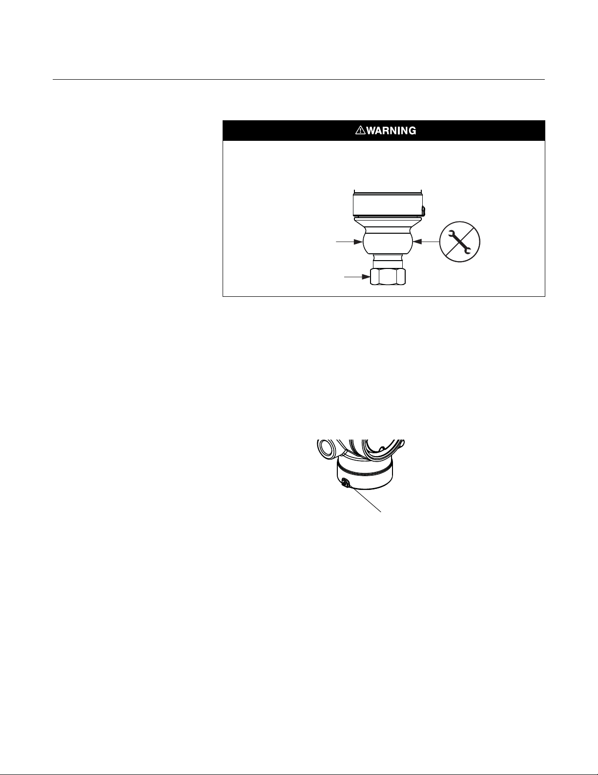
Reference Manual
Sensor Module
Process Connection
5
64
------
Housing Rotation Set
Screw (5/64-in.)
00809-0200-4101, Rev AA
July 2008
Rosemount 2051
Inline Process Connection
Do not apply torque directly to the sensor module. Rotation between the sensor module
and the process connection can damage the electronics. To avoid damage, apply torque
only to the hex-shaped process connection.
Housing Rotation The electronics housing can be rotated up to 180 degrees in either direction to
improve field access, or to better view the optional LCD display. To rotate the
housing, perform the following procedure:
Figure 2-10. Housing Rotation
1. Loosen the housing rotation set screw using a -in. hex wrench.
2. Turn the housing left or right up to 180° from its original position. Over
rotating will damage the transmitter.
3. Retighten the housing rotation set screw.
2-19
Page 30
Reference Manual
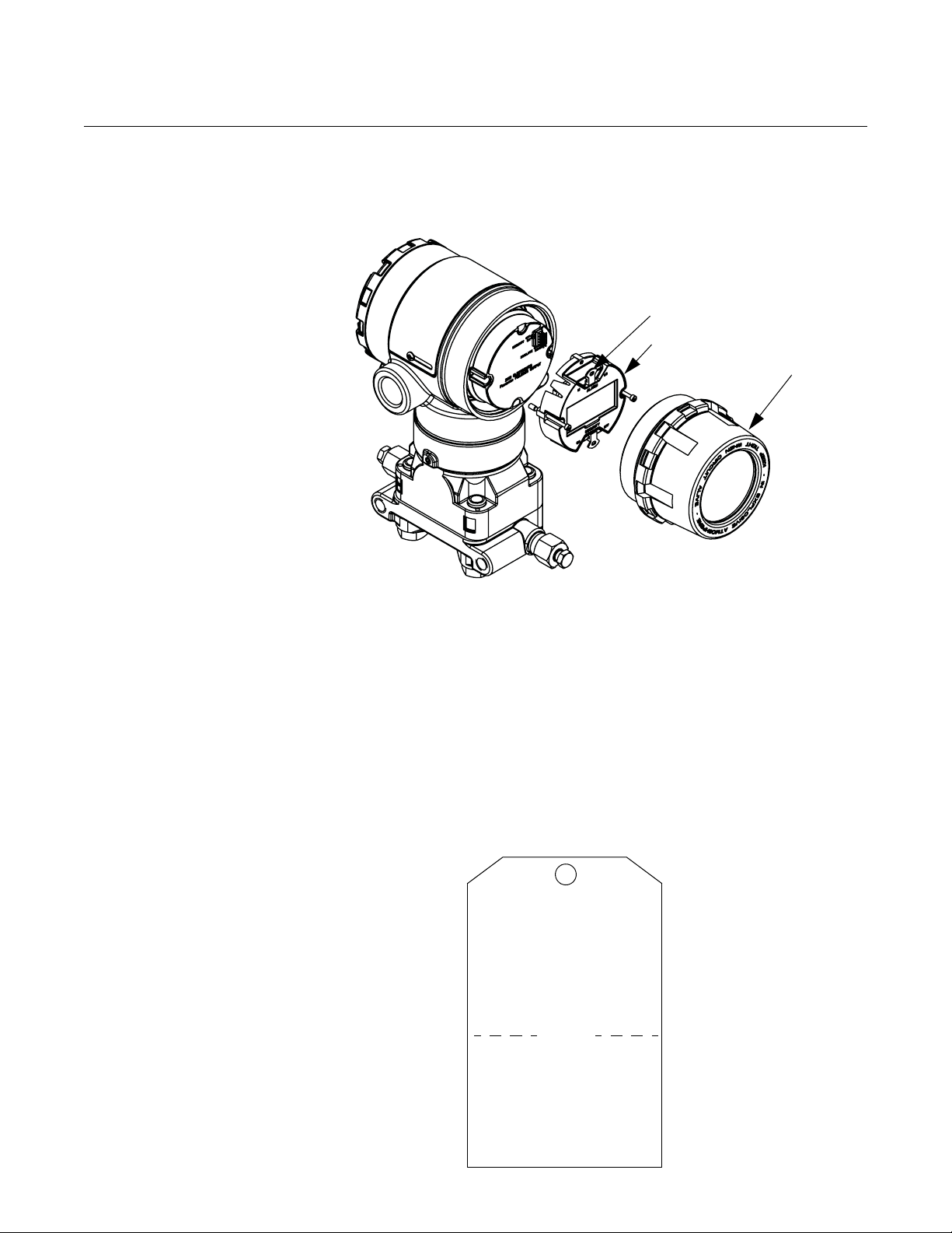
Jumpers (Top and Bottom)
LCD Display
Extended
Cover
COMMISSIONING TAG
Device ID:
0011512051010001440-121698091725
PD Tag:
Device ID:
0011512051010001440-121698091725
PD Tag:
Tea r H ere
00809-0200-4101, Rev AA
Rosemount 2051
July 2008
LCD Display Transmitters ordered with the LCD option are shipped with the display
installed. Installing the display on an existing 2051 transmitter requires a small
instrument screwdriver.
Figure 2-11. LCD Display
.
Tagging Commissioning (Paper) Tag
When commissioning more than one device on a fieldbus segment, it can be
difficult to identify which device is at a particular location. A removable tag
provided with the transmitter can aid in this process by linking the Device ID
and a physical location. TheDevice ID is a unique code that identifies a
particular device in the absence of a device tag. The device tag is used by the
customer as an operational identification for the device and is usually defined
by the Piping and Instrumentation Diagram (P & ID).
2-20
The installer should note the physical location in both places on the
removable commissioning tag and tear off the bottom portion. This should be
done for each device on the segment. The bottom portion of the tags can be
used for commissioning the segment in the control system, providing a direct
link between the Device ID and the tag location.
Page 31

Reference Manual
Sealing
Compound
Conduit
Lines
CORRECT
Possible
Conduit Line
Positions
Sealing
Compound
Possible
Conduit Line
Positions
CORRECT INCORRECT
00809-0200-4101, Rev AA
July 2008
Rosemount 2051
ELECTRICAL CONSIDERATIONS
Conduit Installation
Figure 2-12. Conduit Installation
Diagrams.
NOTE
Make sure all electrical installation is in accordance with national and local code
requirements.
If all connections are not sealed, excess moisture accumulation can damage the
transmitter. Make sure to mount the transmitter with the electrical housing positioned
downward for drainage. To avoid moisture accumulation in the housing, install wiring
with a drip loop, and ensure the bottom of the drip loop is mounted lower than the
conduit connections or the transmitter housing.
Recommended conduit connections are shown in Figure 2-12.
2-21
Page 32

Reference Manual
Trim shield and insulate
Insulate
Shield
Connect Shield Back
to the Power Supply
Ground
00809-0200-4101, Rev AA
Rosemount 2051
July 2008
Wiring Wiring and power supply requirements can be dependent upon the approval
certification. As with all F
power supply and terminating resistors are required for proper operation. The
standard 2051 pressure transmitter terminal block is pictured in Figure 2-13.
The terminals are not polarity sensitive. The transmitter requires 9-32 Vdc to
operate. Type A F
OUNDATION fieldbus wiring 18 awg twisted shielded pair is
recommended.
Avoid running instrument cable next to power cables in cable trays or near
heavy electrical equipment.
It is important that the instrument cable shield:
• be trimmed close and insulated from touching the transmitter housing
• be connected to the next shield if cable is routed through a junction box
• be connected to a good earth ground at the power supply end
OUNDATION fieldbus requirements, a conditioned
Figure 2-13. F
OUNDATION fieldbus Wiring
DP
Do not connect the power signal wiring to the test terminals. Voltage may burn out the
reverse-polarity protection diode in the test connection.
2-22
Page 33

Reference Manual
See “Safety Messages” on page 2-1 for complete warning information.
Trim shield and insulate
Insulate
Shield
Connect Shield Back
to the Power Supply
Ground
00809-0200-4101, Rev AA
July 2008
Rosemount 2051
Perform the following procedure to make wiring connections:
1. Remove the housing cover on terminal compartment side. Do not
remove the cover in explosive atmospheres when the circuit is live.
Signal wiring supplies all power to the transmitter.
2. Connect the leads to the two F
to Figure 2-14.
3. Plug and seal unused conduit connection on the transmitter housing to
avoid moisture accumulation in the terminal side. Install wiring with a drip
loop. Arrange the drip loop so the bottom is lower than the conduit
connections and the transmitter housing.
Power Supply
External power supply required; transmitters operate on 9.0 to 32.0 V dc
transmitter terminal voltage.
OUNDATION fieldbus wiring terminals. Refer
Transient Protection
Terminal Block
The transmitter will withstand electrical transients of the energy level usually
encountered in static discharges or induced switching transients. However,
high-energy transients, such as those induced in wiring from nearby lightning
strikes, can damage the transmitter.
The transient protection terminal block can be ordered as an installed option
(Option Code T1 in the transmitter model number) or as a spare part to retrofit
existing 2051 transmitters in the field. See “Spare Parts” on page A-38 for
spare part numbers. The lightning bolt symbol shown in Figure 2-14 and
Figure identifies the transient protection terminal block.
Figure 2-14. Wiring with transient protection
DP
2-23
Page 34

Rosemount 2051
NOTE
The transient protection terminal block does not provide transient protection
unless the transmitter case is properly grounded. Use the guidelines to
ground the transmitter case. Refer to page 2-25.
Do not run the transient protection ground wire with signal wiring as the
ground wire may carry excessive current if a lightning strike occurs.
Jumpers Security
After you configure the transmitter, you may want to protect the configuration
data from unwarranted changes. Each transmitter is equipped with a security
jumper that can be positioned “ON” to prevent the accidental or deliberate
change of configuration data. The jumper is located on the front side of the
electronics module and is labeled SECURITY (see Figure 2-15).
If the transmitter write protection jumper is in the “ON” position, the transmitter
will not accept any “writes” to its memory. Configuration changes, such as
digital trim and reranging, cannot take place when the transmitter security is
on.
Reference Manual
00809-0200-4101, Rev AA
July 2008
NOTE
If the security jumper is not installed, the transmitter will continue to operate in
the security OFF configuration.
Configuring Transmitter Security Jumper Procedure
To reposition the jumper, follow the procedure described below.
1. Do not remove the transmitter covers in explosive atmospheres when
the circuit is live. If the transmitter is live, set the loop to manual and
remove power.
2. Remove the housing cover opposite the field terminal side. Do not
remove the transmitter covers in explosive atmospheres when the
circuit is live.
3. Reposition the jumpers as desired. Refer to Figure 2-15.
4. Reattach the transmitter cover. Always ensure a proper seal by
installing the electronics housing covers so that metal contacts metal
to meet explosion-proof requirements.
Simulate
The simulate jumper is used in conjunction with the Analog Input (AI) function
block. This switch is used to simulate the measurement. To enable the
simulate feature, insert the jumper across “ENABLE” (see Figure 2-15) while
the transmitter is powered.
2-24
NOTE
When power is cycled to the transmitter, simulate is automatically disabled
regardless of the position of the jumper. This prevents the transmitter from
being accidentally left in simulate mode. Therefore, to enable the simulate
feature, the jumper must be inserted after power is applied to the transmitter.
Page 35

Reference Manual
Simulate Jumper
Security Jumper
00809-0200-4101, Rev AA
July 2008
Figure 2-15. Transmitter
Jumper Locations
Rosemount 2051
Grounding Use the following techniques to properly ground the transmitter case:
Transmitter Case
Always ground the transmitter case in accordance with national and local
electrical codes. The most effective transmitter case grounding method is a
direct connection to earth ground with minimal impedance. Methods for
grounding the transmitter case include:
• Internal Ground Connection: The Internal Ground Connection screw
is inside the FIELD TERMINALS side of the electronics housing. This
screw is identified by a ground symbol ( ). The ground connection
screw is standard on all Rosemount 2051 transmitters. Refer to
Figure 2-16.
• External Ground Assembly: This assembly is included with the
optional transient protection terminal block (Option Code T1), and it is
included with various hazardous location certifications. The External
Ground Assembly can also be ordered with the transmitter (Option
Code V5), or as a spare part. See “Spare Parts” on page A-25. Refer to
Figure 2-17 for location of the External Ground Screw.
2-25
Page 36

Rosemount 2051
Internal Ground
Connection Screw
External Ground
Assembly
Figure 2-16. Internal Ground
Screw
Figure 2-17. External Ground
Assembly
Reference Manual
00809-0200-4101, Rev AA
July 2008
2-26
NOTE
Grounding the transmitter case via threaded conduit connection may not
provide sufficient ground continuity.
Page 37

Reference Manual
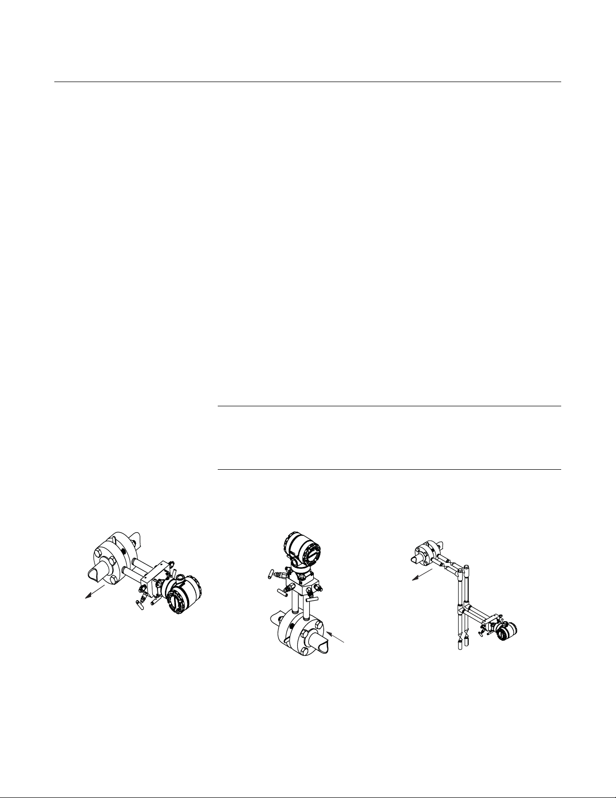
2051C AND 305
INTEGRAL COPLANAR
2051C AND 305
INTEGRAL TRADITIONAL
2051T AND 306
IN-LINE
2051C AND 304
CONVENTIONAL
00809-0200-4101, Rev AA
July 2008
Rosemount 2051
HAZARDOUS LOCATIONS CERTIFICATIONS
ROSEMOUNT 305, 306 AND 304 MANIFOLDS
Figure 2-18. Manifolds
Individual transmitters are clearly marked with a tag indicating the approvals
they carry. Transmitters must be installed in accordance with all applicable
codes and standards to maintain these certified ratings. Refer to Appendix B:
Approval Information for information on these approvals.
The 305 Integral Manifold is available in two designs: Traditional and
Coplanar. The traditional 305 Integral Manifold can be mounted to most
primary elements with mounting adapters in the market today. The 306
Integral Manifold is used with the 2051T in-line transmitters to provide
block-and-bleed valve capabilities of up to 10000 psi (690 bar).
2-27
Page 38

Rosemount 2051
See “Safety Messages” on page 2-1 for complete warning information.
Reference Manual
00809-0200-4101, Rev AA
July 2008
Rosemount 305 Integral
Manifold Installation
Procedure
To install a 305 Integral Manifold to a 2051 transmitter:
1. Inspect the PTFE sensor module o-rings. Undamaged o-rings may be
reused. If the o-rings are damaged (if they have nicks or cuts, for
example), replace with o-rings designed for Rosemount transmitter.
IMPORTANT
If replacing the o-rings, take care not to scratch or deface the o-ring grooves
or the surface of the isolating diaphragm while you remove the damaged
o-rings.
2. Install the Integral Manifold on the sensor module. Use the four 2.25-in.
manifold bolts for alignment. Finger tighten the bolts, then tighten the
bolts incrementally in a cross pattern to final torque value. See “Flange
Bolts” on page 2-13 for complete bolt installation information and torque
values. When fully tightened, the bolts should extend through the top of
the sensor module housing.
3. If the PTFE sensor module o-rings have been replaced, the flange bolts
should be re-tightened after installation to compensate for cold flow of
the o-rings.
NOTE
Always perform a zero trim on the transmitter/manifold assembly after
installation to eliminate mounting effects.
Rosemount 306 Integral
Manifold Installation
Procedure
Rosemount 304
Conventional Manifold
Installation Procedure
The 306 Manifold is for use only with a 2051T In-line transmitter.
Assemble the 306 Manifold to the 2051T In-line transmitter with a
thread sealant.
To install a 304 Conventional Manifold to a 2051 transmitter:
1. Align the Conventional Manifold with the transmitter flange. Use the four
manifold bolts for alignment.
2. Finger tighten the bolts, then tighten the bolts incrementally in a cross
pattern to final torque value. See “Flange Bolts” on page 2-6 for complete
bolt installation information and torque values. When fully tightened, the
bolts should extend through the top of the sensor module housing.
3. Leak-check assembly to maximum pressure range of transmitter.
2-28
Page 39

Reference Manual
Drain/
Vent
Valve
Drain/
Vent
Valve
Equalize
(closed)
Process
Isolate
(open)
Isolate
(open)
H
L
In normal operation the two isolate valves between the
process and instrument ports will be open and the
equalizing valve(s) will be closed.
Drain/
Vent
Valve
Equalize
(closed)
Process
Isolate
(closed)
Isolate
(open)
H
L
To zero the 2051, close the isolate valve to the low
pressure (downstream side) of the transmitter first.
Drain/
Vent
Valve
Drain/
Vent
Valve
Equalize
(open)
Process
Isolate
(closed)
Isolate
(open)
H
L
Next, open the center (equalize) valve(s) to equalize
the pressure on both sides of the transmitter.
00809-0200-4101, Rev AA
July 2008
Integral Manifold Operation
Three-valve configuration shown.
Rosemount 2051
2-29
Page 40

Rosemount 2051
Drain/
Vent
Valve
Drain/
Vent
Valve
Equalize
(closed)
Process
Isolate
(closed)
Isolate
(open)
H
L
The manifold valves are now in the proper configuration
for zeroing the transmitter. To return the transmitter to
service, close the equalizing valve(s) first.
Drain/
Vent
Valve
Drain/
Vent
Valve
Equalize
(closed)
Process
Isolate
(open)
Isolate
(open)
H
L
Next, open the isolate valve on the low pressure side of
the transmitter.
Reference Manual
00809-0200-4101, Rev AA
July 2008
2-30
Page 41

Reference Manual
ZERO
SUPRESSION
mA dc
20
540
900
inH2O
4
Figure 2-19. Liquid Level
Measurement Example.
Let X equal the vertical distance between the minimum and maximum
measurable levels (500 in.).
Let Y equal the vertical distance betw een the transmitter datum line and the
minimum measurable level (100 in.).
Let SG equal the specific gravity of the fluid (0.9).
Let h equal the maximum head pressure to be measured in inches of water.
Let e equal head pressure produced by Y expressed in inches of water.
Let Range equal e to e + h.
Then h = (X)(SG)
= 500 x 0.9
= 450 inH
2
O
e= (Y)(SG)
= 100 x 0.9
=90 inH
2
O
Range = 90 to 540 inH
2
O
T
Y
X
00809-0200-4101, Rev AA
July 2008
Rosemount 2051
LIQUID LEVEL MEASUREMENT
Differential pressure transmitters used for liquid level applications measure
hydrostatic pressure head. Liquid level and specific gravity of a liquid are
factors in determining pressure head. This pressure is equal to the liquid
height above the tap multiplied by the specific gravity of the liquid. Pressure
head is independent of volume or vessel shape.
Open Vessels A pressure transmitter mounted near a tank bottom measures the pressure of
the liquid above.
Make a connection to the high pressure side of the transmitter, and vent the
low pressure side to the atmosphere. Pressure head equals the liquid’s
specific gravity multiplied by the liquid height above the tap.
Zero range suppression is required if the transmitter lies below the zero point
of the desired level range. Figure 2-19 shows a liquid level measurement
example.
Closed Vessels Pressure above a liquid affects the pressure measured at the bottom of a
closed vessel. The liquid specific gravity multiplied by the liquid height plus
the vessel pressure equals the pressure at the bottom of the vessel.
To measure true level, the vessel pressure must be subtracted from the
vessel bottom pressure. To do this, make a pressure tap at the top of the
vessel and connect this to the low side of the transmitter. Vessel pressure is
then equally applied to both the high and low sides of the transmitter. The
resulting differential pressure is proportional to liquid height multiplied by the
liquid specific gravity.
Dry Leg Condition
Low-side transmitter piping will remain empty if gas above the liquid does not
condense. This is a dry leg condition. Range determination calculations are
the same as those described for bottom-mounted transmitters in open
vessels, as shown in Figure 2-19.
2-31
Page 42

Rosemount 2051
Figure 2-20. Wet Leg Example.
Let X equal the vertical distance between the minimum and maximum
measurable levels (500 in.).
Let Y equal the vertical distance between the transmitter datum line and the
minimum measurable level (50 in.).
Let z equal the vertical distance between the top of the liquid in the wet leg
and the transmitter datum line (600 in.).
Let SG
1
equal the specific gravity of the fluid (1.0).
Let SG
2
equal the specific gravity of the fluid in the wet leg (1.1).
Let h equal the maximum head pressure to be measured in inches of water.
Let e equal the head pressure produced by Y expressed in inches of water.
Let s equal head pressure produced by z expressed in inches of water.
Let Range equal e – s to h + e – s.
Then h = (X)(SG
1
)
= 500 x 1.0
= 500 in H
2
O
e= (Y)(SG
1
)
=50 x 1.0
=50 inH
2
O
s= (z)(SG
2
)
= 600 x 1.1
= 660 inH
2
0
Range = e – s to h + e – s.
= 50 – 660 to 500 + 50 – 660
= –610 to –110 inH
2
0
ZERO ELEVATION
LT
Y
H L
mA dc
20
0
4
-110-610
inH2O
X
Z
Reference Manual
00809-0200-4101, Rev AA
July 2008
Wet Leg Condition
Condensation of the gas above the liquid slowly causes the low side of the
transmitter piping to fill with liquid. The pipe is purposely filled with a
convenient reference fluid to eliminate this potential error. This is a wet leg
condition.
The reference fluid will exert a head pressure on the low side of the
transmitter. Zero elevation of the range must then be made. See Figure 2-20
2-32
Page 43

Reference Manual
Figure 2-21. Bubbler Liquid Level
Measurement Example.
mA dc
Let X equal the vertical distance between the minimum and maximum
measurable levels (100 in.).
Let SG equal the specific gravity of the fluid (1.1).
Let h equal the maximum head pressure to be measured in inches of water.
Let Range equal zero to h.
Then h = (X)(SG)
= 100 x 1.1
= 110 inH
2
O
Range = 0 to 110 inH
2
O
20
inH2O
0
4
110
T
AIR
X
00809-0200-4101, Rev AA
July 2008
Rosemount 2051
Bubbler System in Open Vessel
A bubbler system that has a top-mounted pressure transmitter can be used in
open vessels. This system consists of an air supply, pressure regulator,
constant flow meter, pressure transmitter, and a tube that extends down into
the vessel.
Bubble air through the tube at a constant flow rate. The pressure required to
maintain flow equals the liquid’s specific gravity multiplied by the vertical
height of the liquid above the tube opening. Figure 2-21 shows a bubbler
liquid level measurement example.
2-33
Page 44

Rosemount 2051
Reference Manual
00809-0200-4101, Rev AA
July 2008
2-34
Page 45

Reference Manual
00809-0200-4101, Rev AA
July 2008
Rosemount 2051
Section 3 Configuration
Overview . . . . . . . . . . . . . . . . . . . . . . . . . . . . . . . . . . . . . . . page 3-1
Safety Messages . . . . . . . . . . . . . . . . . . . . . . . . . . . . . . . . . page 3-1
Device Capabilities . . . . . . . . . . . . . . . . . . . . . . . . . . . . . . . page 3-2
General Block Information . . . . . . . . . . . . . . . . . . . . . . . . . page 3-2
Resource Block . . . . . . . . . . . . . . . . . . . . . . . . . . . . . . . . . . page 3-3
Analog Input (AI) Function Block . . . . . . . . . . . . . . . . . . . page 3-5
LCD Block . . . . . . . . . . . . . . . . . . . . . . . . . . . . . . . . . . . . . . page 3-11
OVERVIEW This section covers basic operation, software functionality, and basic
configuration procedures for the Rosemount 2051 pressure transmitter with
F
OUNDATION fieldbus. This section is organized by block information. For
detailed information about the function blocks used in the Rosemount 2051
Pressure Transmitter, refer to "Foundation Fieldbus Block Information" in the
F
OUNDATION fieldbus Block manual (00809-0100-4783).
SAFETY MESSAGES Procedures and instructions in this section may require special precautions to
ensure the safety of the personnel performing the operations. Information that
raises potential safety issues is indicated by a warning symbol ( ). Refer to
the following safety messages before performing an operation preceded by
this symbol.
Warnings
Explosions can result in death or serious injury.
• Do not remove the transmitter covers in explosive environments when the
circuit is live.
• Transmitter covers must be fully engaged to meet explosion proof
requirements.
• Before connecting a configuration tool in an explosive atmosphere, make sure
the instruments in the loop are installed in accordance with intrinsically safe or
nonincendive field wiring practices.
Electrical shock can result in death or serious injury.
• Avoid contact with the leads and terminals. High voltage that may be present
on leads can cause electrical shock.
www.rosemount.com
Page 46

Reference Manual
00809-0200-4101, Rev AA
Rosemount 2051
July 2008
DEVICE CAPABILITIES
Link Active Scheduler The Rosemount 2051 can be designated to act as the backup Link Active
Scheduler (LAS) in the event that the LAS is disconnected from the segment.
As the backup LAS, the 2051 will take over the management of
communications until the host is restored.
The host system may provide a configuration tool specifically designed to
designate a particular device as a backup LAS.
Capabilities Block Execution times
Analog Input = 30 ms
PID = 45 ms
GENERAL BLOCK INFORMATION
Modes
The Resource, Transducer, and all function blocks in the device have modes
of operation. These modes govern the operation of the block. Every block
supports both automatic (AUTO) and out of service (OOS) modes. Other
modes may also be supported.
Changing Modes
To change the operating mode, set the MODE_BLK.TARGET to the desired
mode. After a short delay, the parameter MODE_BLOCK.ACTUAL should
reflect the mode change if the block is operating properly.
Permitted Modes
It is possible to prevent unauthorized changes to the operating mode of a
block. To do this, configure MODE_BLOCK.PERMITTED to allow only the
desired operating modes. It is recommended to always select OOS as one of
the permitted modes.
Types of Modes
For the procedures described in this manual, it will be helpful to understand
the following modes:
AUTO
The functions performed by the block will execute. If the block has any
outputs, these will continue to update. This is typically the normal
operating mode.
3-2
Out of Service (OOS)
The functions performed by the block will not execute. If the block has any
outputs, these will typically not update and the status of any values passed
to downstream blocks will be “BAD”. To make some changes to the
configuration of the block, change the mode of the block to OOS. When
the changes are complete, change the mode back to AUTO.
MAN
In this mode, variables that are passed out of the block can be manually
set for testing or override purposes.
Page 47

Reference Manual
Resource
Block
Transducer
Block
Analog Input
(AI Block)
Other
function
blocks
00809-0200-4101, Rev AA
July 2008
Rosemount 2051
Other Types of Modes
Other types of modes are Cas, RCas, ROut, IMan and LO. Some of these
may be supported by different function blocks in the Rosemount 2051. For
more information, see the Function Block manual, document
00809-0100-4783.
NOTE
When an upstream block is set to OOS, this will impact the output status of all
downstream blocks. The figure below depicts the hierarchy of blocks:
Simulation Simulation is the functionality of the AI block. To support testing, either
change the mode of the block to manual and adjust the output value or enable
simulation through the configuration tool and manually enter a value for the
measurement value and its status (this single value will apply to all outputs).
In both cases, first set the ENABLE jumper on the field device.
RESOURCE BLOCK
FEATURES and
FEATURES_SEL
NOTE
All fieldbus instruments have a simulation jumper. As a safety measure, the
jumper has to be reset every time there is a power interruption. This measure
is to prevent devices that went through simulation in the staging process from
being installed with simulation enabled.
With simulation enabled, the actual measurement value has no impact on the
OUT value or the status. The OUT values will all have the same value as
determined by the simulate value.
The FEATURES parameter is read only and defines which features are
supported by the 2051. Below is a list of the FEATURES the 2051 supports.
FEATURES_SEL is used to turn on any of the supported features that are
found in the FEATURES parameter. The default setting of the Rosemount
2051 does not select any of these features. Choose one or more of the
supported features if any.
UNICODE
All configurable string variables in the 2051, except tag names, are octet
strings. Either ASCII or Unicode may be used. If the configuration device is
generating Unicode octet strings, you must set the Unicode option bit.
REPORTS
The 2051 supports alert reports. The Reports option bit must be set in the
features bit string to use this feature. If it is not set, the host must poll for
alerts. If this bit is set, the transmitter will actively report alerts.
3-3
Page 48

Rosemount 2051
Reference Manual
00809-0200-4101, Rev AA
July 2008
SOFT W LOCK and HARD W LOCK
Inputs to the security and write lock functions include the hardware security
switch, the hardware and software write lock bits of the FEATURE_SEL
parameter, the WRITE_LOCK parameter, and the DEFINE_WRITE_LOCK
parameter.
The WRITE_LOCK parameter prevents modification of parameters within the
device except to clear the WRITE_LOCK parameter. During this time, the
block will function normally updating inputs and outputs and executing
algorithms. When the WRITE_LOCK condition is cleared, a WRITE_ALM
alert is generated with a priority that corresponds to the WRITE_PRI
parameter.
The FEATURE_SEL parameter enables the user to select a hardware or
software write lock or no write lock capability. To enable the hardware security
function, enable the HW_SEL bit in the FEATURE_SEL parameter. When this
bit has been enabled the WRITE_LOCK parameter becomes read only and
will reflect the state of the hardware switch. In order to enable the software
write lock, the SW_SEL bit must be set in the FEATURE_SEL parameter.
Once this bit is set, the WRITE_LOCK parameter may be set to “Locked” or
“Not Locked.” Once the WRITE_LOCK parameter is set to “Locked” by either
the software or the hardware lock, all user requested writes as determined by
the DEFINE_WRITE_LOCK parameter shall be rejected.
The DEFINE_WRITE_LOCK parameter allows the user to configure whether
the write lock functions (both software and hardware) will control writing to all
blocks, or only to the resource and transducer blocks. Internally updated data
such as process variables and diagnostics will not be restricted by the
security switch.
The following table displays all possible configurations of the WRITE_LOCK
parameter.
FEATURE_SEL
HW_SEL bit
0 (off) 0 (off) NA 1 (unlocked) Read only NA All
0 (off) 1 (on) NA 1 (unlocked) Read/Write NA All
0 (off) 1 (on) NA 2 (locked) Read/Write Physical Function
0 (off) 1 (on) NA 2 (locked) Read/Write Everything None
1 (on) 0 (off)
1 (on) 0 (off) 1 (locked) 2 (locked) Read only Physical Function
1 (on) 0 (off) 1 (locked) 2 (locked) Read only Everything None
(1) The hardware and software write lock select bits are mutually exclusive and the hardware select has the highest priority. When the HW_SEL bit if set to 1
(on), the SW_SEL bit is automatically set to 0 (off) and is read only.
FEATURE_SEL
SW_SEL bit
(1)
WRITE_LOCK
SECURITY SWITCH WRITE_LOCK
0 (unlocked) 1 (unlocked) Read only NA All
Read/Write
DEFINE_WRITE_LOCK
Write access
to blocks
Blocks only
Blocks only
MAX_NOTIFY The MAX_NOTIFY parameter value is the maximum number of alert reports
that the resource can have sent without getting a confirmation, corresponding
to the amount of buffer space available for alert messages. The number can
be set lower, to control alert flooding, by adjusting the LIM_NOTIFY
parameter value. If LIM_NOTIFY is set to zero, then no alerts are reported.
3-4
Page 49

Reference Manual
00809-0200-4101, Rev AA
July 2008
ANALOG INPUT (AI) FUNCTION BLOCK
Rosemount 2051
Configure the AI block
A minimum of four parameters are required to configure the AI Block. The
parameters are described below with example configurations shown at the
end of this section.
CHANNEL
Select the channel that corresponds to the desired sensor measurement. The
2051 measures both pressure (channel 1) and sensor temperature (channel
2).
Table 3-1. I/O Channel Definitions
Channel Number Channel Description
1 differential pressure in AI.XD_SCALE units
2 sensor temperature in AI.XD_SCALE units
L_TYPE
The L_TYPE parameter defines the relationship of the sensor measurement
(pressure or sensor temperature) to the desired output of the AI Block (e.g.
pressure, level, flow, etc.). The relationship can be direct, indirect, or indirect
square root.
Direct
Select direct when the desired output will be the same as the sensor
measurement (pressure or sensor temperature).
Indirect
Select indirect when the desired output is a calculated measurement
based on the sensor measurement (e.g. a pressure measurement is made
to determine level in a tank). The relationship between the sensor
measurement and the calculated measurement will be linear.
Indirect Square Root
Select indirect square root when the desired output is an inferred
measurement based on the sensor measurement and the relationship
between the sensor measurement and the inferred measurement is
square root (e.g. flow).
XD_SCALE and OUT_SCALE
The XD_SCALE and OUT_SCALE each include three parameters: 0%,
100%, and, engineering units. Set these based on the L_TYPE:
L_TYPE is Direct
When the desired output is the measured variable, set the XD_SCALE to
the “Primary_Value_Range”. This is found in the Sensor Transducer Block.
Set OUT_SCALE to match XD_SCALE.
L_TYPE is Indirect
When an inferred measurement is made based on the sensor
measurement, set the XD_SCALE to represent the operating range that
the sensor will see in the process. Determine the inferred measurement
values that correspond to the XD_SCALE 0 and 100% points and set
these for the OUT_SCALE.
3-5
Page 50

Rosemount 2051
Reference Manual
00809-0200-4101, Rev AA
July 2008
L_TYPE is Indirect Square Root
When an inferred measurement is made based on the sensor
measurement AND the relationship between the inferred measurement
and sensor measurement is square root, set the XD_SCALE to represent
the operating range that the sensor will see in the process. Determine the
inferred measurement values that correspond to the XD_SCALE 0 and
100% points and set these for the OUT_SCALE.:
Pressure (Channel 1) Temperature (Channel 2)
Pa °C
kPa °F
bar
mbar
torr
atm
psi
2
g/cm
2
kg/cm
inH2O at 68 °F
mmH2O at 68 °F
mmH2O at 4 °F
inHg at 0 °C
mmHg at 0 °C
NOTE
When the engineering units of the XD_SCALE are selected, this causes the
engineering units of the PRIMARY_VALUE_RANGE in the Transducer Block
to change to the same units. THIS IS THE ONLY WAY TO CHANGE THE
ENGINEERING UNITS IN THE SENSOR TRANSDUCER BLOCK,
PRIMARY_VALUE_RANGE parameter.
Configuration Examples
Pressure transmitter Situation #1
A pressure transmitter with a range of 0 – 100 psi.
Solution
Table 3-2 lists the appropriate configuration settings.
Table 3-2. Analog Input function
block configuration for a typical
pressure transmitter.
Pressure transmitter used to
measure level in an open tank
.
Parameter Configured Values
L_TYPE Direct
XD_SCALE Primary_Value_Range
OUT_SCALE Primary_Value_Range
Channel 1 - pressure
Situation #2
The level of an open tank is to be measured using a pressure tap at the
bottom of the tank. The maximum level at the tank is 16 ft. The liquid in the
tank has a density that makes the maximum level correspond to a pressure of
7.0 psi at the pressure tap (see Figure 3-1).
3-6
Page 51

Rosemount 2051
16 ft
7.0 psi measured at
the transmitter
Full Tank
OUT = PV – XD_SCALE_0% * (OUT_SCALE_100% – OUT_SCALE_0%) + OUT_SCALE_0%
XD_SCALE_100% – XD_SCALE_0%
OUT = 5 psi – 0 psi * (16 ft. – 0 ft.) + 0 ft. = 11.43 ft.
7 psi – 0 psi
Figure 3-1. Situation #2
Diagram.
Reference Manual
00809-0200-4101, Rev AA
July 2008
Solution to Situation #2
Table 3-3. Analog Input function
block configuration for a
pressure transmitter used in
level measurement
(situation #1).
Table 3-3 lists the appropriate configuration settings.
Parameter Configured Values
L_TYPE Indirect
XD_SCALE 0 to 7 psi
OUT_SCALE 0 to 16 ft
Channel 1 - pressure
Output calculation for Situation #2
When the L_Type is configured as Indirect, the OUT parameter
is calculated as:
In this example, when PV is 5 psi, then the OUT parameter will be
calculated as follows:
3-7
Page 52

Rosemount 2051
16 ft
0 ft
2.0 psi measured at
the transmitter
Empty Tank
OUT = 4 psi – 2 psi * (16 ft. – 0 ft.) + 0 ft. = 4.57 ft.
9 psi – 2 psi
Figure 3-2. Situation #3
Diagram.
Reference Manual
00809-0200-4101, Rev AA
July 2008
Situation #3
The transmitter in situation #3 is installed below the tank in a position where
the liquid column in the impulse line, with an empty tank, is equivalent to 2.0
psi (see Figure 3-2).
Table 3-4. Analog Input function
block configuration for a
pressure transmitter used in
level measurement
(Situation #3).
Differential pressure
transmitter to measure flow
Solution to situation #3
Table 3-4 lists the appropriate configuration settings.
Parameter Configured Values
L_TYPE Indirect
XD_SCALE 2 to 9 psi
OUT_SCALE 0 to 16 ft
Channel 1 - pressure
In this example, when the PV is 4 psi, OUT will be calculated as follows:
Situation #4
The liquid flow in a line is to be measured using the differential pressure
across an orifice plate in the line. Based on the orifice specification sheet, the
differential pressure transmitter was calibrated for 0 to 20 inH
0 for a flow of 0
2
to 800 gal/min.
3-8
Page 53

Rosemount 2051
Out
PV XDSCALE0–
XDSCALE100
-------------------------------------------------
OUTSCALE100 OUTSCALE0–()OUTSCALE0+=
OUT
8inH2O0inH
2
O–
20i nH2O0inH
2
O–
------------------------------------------------------
=
(800gal/min. - 0gal/min.) + 0gal/min. = 505.96gal/min.
PV_FTIME
63% of Change
OUT (mode in man)
OUT (mode in auto)
PV
Time (seconds)
FIELD_VAL
Table 3-5. Analog Input
Function Block Configuration for
a Differential Pressure
Transmitter.
Solution
Table 3-5 lists the appropriate configuration settings.
Parameter Configured Values
L_TYPE Indirect Square Root
XD_SCALE 0 to 20 in.H
OUT_SCALE 0 to 800 gal/min.
Channel 1 - pressure
O
2
Reference Manual
00809-0200-4101, Rev AA
July 2008
Filtering The filtering feature changes the response time of the device to smooth
variations in output readings caused by rapid changes in input. Adjust the
filter time constant (in seconds) using the PV_FTIME parameter. Set the filter
time constant to zero to disable the filter feature.
Figure 3-3. Analog Input
PV_FTIME filtering Diagram.
Low Cutoff When the converted input value is below the limit specified by the LOW_CUT
parameter, and the Low Cutoff I/O option (IO_OPTS) is enabled (True), a
value of zero is used for the converted value (PV). This option is useful to
eliminate false readings when the differential pressure measurement is close
to zero, and it may also be useful with zero-based measurement devices such
as flowmeters.
3-9
NOTE
Low Cutoff is the only I/O option supported by the AI block. Set the I/O option
in Manual or Out of Service mode only.
Page 54

Reference Manual
00809-0200-4101, Rev AA
Rosemount 2051
July 2008
Process Alarms Process Alarm detection is based on the OUT value. Configure the alarm
limits of the following standard alarms:
• High (HI_LIM)
• High high (HI_HI_LIM)
• Low (LO_LIM)
• Low low (LO_LO_LIM)
In order to avoid alarm chattering when the variable is oscillating around the
alarm limit, an alarm hysteresis in percent of the PV span can be set using the
ALARM_HYS parameter. The priority of each alarm is set in the following
parameters:
•HI_PRI
• HI_HI_PRI
•LO_PRI
• LO_LO_PRI
Alarm Priority Alarms are grouped into five levels of priority:
Priority
Number
0 The alarm condition is not used.
1 An alarm condition with a priority of 1 is recognized by the system, but is not
2 An alarm condition with a priority of 2 is reported to the operator.
3-7 Alarm conditions of priority 3 to 7 are advisory alarms of increasing priority.
8-15 Alarm conditions of priority 8 to 15 are critical alarms of increasing priority.
Priority Description
reported to the operator.
Status Options Status Options (STATUS_OPTS) supported by the AI block are shown below:
Propagate Fault Forward
If the status from the sensor is Bad, Device failure or Bad, Sensor failure,
propagate it to OUT without generating an alarm. The use of these sub-status
in OUT is determined by this option. Through this option, the user may
determine whether alarming (sending of an alert) will be done by the block or
propagated downstream for alarming.
Uncertain if Limited
Set the output status of the Analog Input block to uncertain if the measured or
calculated value is limited.
BAD if Limited
Set the output status to Bad if the sensor is violating a high or low limit.
Uncertain if Man Mode
Set the output status of the Analog Input block to uncertain if the actual mode
of the block is Man.
NOTES
The instrument must be in Out of Service mode to set the status option.
3-10
Page 55

Reference Manual
00809-0200-4101, Rev AA
Rosemount 2051
July 2008
Advanced Features The AI Function Block provides added capability through the addition of the
following parameters:
ALARM_SEL
ALARM_SEL allows one or more of the process alarm conditions detected by
the AI function block to be used in setting its OUT_D parameter.
OUT_D
OUT_D is the discrete output of the AI function block based on the detection
of process alarm condition(s). This parameter may be linked to other function
blocks that require a discrete input based on the detected alarm condition.
LCD BLOCK The LCD can display up to four different parameters. If a parameter from a
function block is displayed, then the function block must be scheduled
(downloaded) in order for it to be displayed on the LCD. If a parameter from a
different device is displayed, it must be linked to a block in the Rosemount
2051 transmitter with the LCD display and it must be downloaded. It can
display any input or output parameter of any block in the Rosemount 2051.
The first display is pre-configured to show the value of the transducer block of
the Rosemount 2051. This value can be left or changed.
Figure 3-4. Transducer500
Properties: Process Screen
1. Open the LCD block by double clicking on the LCD transducer block in
Deltav Explorer.
Figure 3-4 will appear. Make sure the block is in "Automatic" mode. Then
select the "Local Display" tab.
3-11
Page 56

Rosemount 2051
Figure 3-5. Transducer500
Properties Local Display Screen
Reference Manual
00809-0200-4101, Rev AA
July 2008
For each parameter n(n =1 - 4) displayed on the LCD there are several fields
in the "Local Display" tab that must be setup.
1. The first parameter is called "BLOCK TAG_n," here you must enter the
exact name of the block to be displayed. This must be the same name as
the one that is stored in the device.
2. Then select "BLOCK TYPE_n". This is a drop down menu showing the
selections available in the device. Select the disired block to be
displayed, in the "BLK_TYPE_n" field.
3. Select "UNITS_TYPE_n". Select "Custom" in this parameter if bringing a
value from outside the Rosemount 2051 device. "Auto" has only
pressure units, which might or might not match the disired selection.
4. The next parameter is called "CUSTOM_TAG_n.” This is an optional
selection in identifying which parameter, block or device to be viewed on
the LCD. This can be any name up to five characters long.
5. Then select "PARAM_INDEX_n". This is a drop down menu and the
selections available in the device will appear. Select which parameter is
to be displayed, in the "PARAM_INDEX_n" field.
6. Select "CUSTOM_UNITS_n” if "Custom" was selected previously in the
"UNITS_TYPE_n" field above. This is limited to five characters and is
where the disired units you wish to be displayed are entered.
7. To display more than one parameter be sure and check the appropriate
number of boxes in the "Display Parameter Select" field.
3-12
Page 57

Reference Manual
00809-0200-4101, Rev AA
July 2008
Rosemount 2051
Section 4 Operation and Maintenance
Overview . . . . . . . . . . . . . . . . . . . . . . . . . . . . . . . . . . . . . . . page 4-1
Safety Messages . . . . . . . . . . . . . . . . . . . . . . . . . . . . . . . . . page 4-1
Status . . . . . . . . . . . . . . . . . . . . . . . . . . . . . . . . . . . . . . . . . . page 4-2
Calibration . . . . . . . . . . . . . . . . . . . . . . . . . . . . . . . . . . . . . . page 4-3
OVERVIEW This section contains information on operation and maintenance procedures.
METHODS AND MANUAL OPERATION
Each F
displaying and performing operations. Some hosts will use Device
Descriptions (DD) and DD Methods to complete device configuration and will
display data consistently across platforms. The DD can found on Foundation’s
website at www.fieldbus.org. There is no requirement that a host or
configuration tool support these features.
OUNDATION fieldbus host or configuration tool has different ways of
For DeltaV users, the DD can be found at www.easydeltav.com. The
information in this section will describe how to use methods in a general
fashion. In addition, if your host or configuration tool does not support
methods this section will cover manually configuring the parameters involved
with each method operation. For more detailed information on the use of
methods, see your host or configuration tool manual.
SAFETY MESSAGES Procedures and instructions in this section may require special precautions to
ensure the safety of the personnel performing the operations. Information that
raises potential safety issues is indicated by a warning symbol ( ). Refer to
the following safety messages before performing an operation preceded by
this symbol.
Warnings
Explosions can result in death or serious injury.
• Do not remove the transmitter covers in explosive environments when the circuit is
live.
• Transmitter covers must be fully engaged to meet explosion proof requirements.
• Before connecting a communicator in an explosive atmosphere, make sure the
instruments in the loop are installed in accordance with intrinsically safe or
nonincendive field wiring practices.
www.rosemount.com
Page 58

Reference Manual
00809-0200-4101, Rev AA
Rosemount 2051
Electrical shock can result in death or serious injury.
• Avoid contact with the leads and terminals. High voltage that may be present on
leads can cause electrical shock.
Performing a 'Restart with defaults' will set all function block information in the device to
factory defaults. This includes the clearing of all function block links and schedule, as well
as defaulting all Resource and Transducer Block user data.
July 2008
STATUS Along with the measured or calculated PV value, every FOUNDATION Fieldbus
block passes an additional parameter called STATUS. The PV and STATUS
are passed from the Transducer Block to the Analog Input Block. The
STATUS can be one of the following: GOOD, BAD, or UNCERTAIN. When
there are no problems detected by the self-diagnostics of the block, the
STATUS will be GOOD. If a problem occurs with the hardware in the device,
or, the quality of the process variable is compromised for some reason, the
STATUS will become either BAD or UNCERTAIN depending upon the nature
of the problem. It is important that the Control Strategy that makes use of the
Analog Input Block is configured to monitor the STATUS and take action
where appropriate when the STATUS is no longer GOOD.
Master Reset Method Resource Block
To perform a master reset, run the Master Reset Method. If your system does
not support methods, manually configure the Resource Block parameters
listed below.
1. Set the RESTART to one of the options below:
• Run - Default State
• Resource - Not Used
• Defaults - Sets all device parameters to F
OUNDATION fieldbus default
values
• Processor - Does a software reset of the CPU
Simulation Simulate replaces the channel value coming from the Sensor Transducer
Block. For testing purposes, it is possible to manually drive the output of the
Analog Input Block to a desired value. There are two ways to do this.
Manual Mode
To change only the OUT_VALUE and not the OUT_STATUS of the AI Block,
place the TARGET MODE of the block to MANUAL. Then, change the
OUT_VALUE to the desired value.
Simulate
1. If the SIMULATE switch is in the OFF position, move it to the ON
position. If the SIMULATE jumper is already in the ON position, you must
move it to off and place it back in the ON position.
4-2
Page 59

Reference Manual
00809-0200-4101, Rev AA
July 2008
CALIBRATION
Rosemount 2051
NOTE
As a safety measure, the switch must be reset every time power is interrupted
to the device in order to enable SIMULATE. This prevents a device that is
tested on the bench from getting installed in the process with SIMULATE still
active.
2. To change both the OUT_VALUE and OUT_STATUS of the AI Block, set
the TARGET MODE to AUTO.
3. Set SIMULATE_ENABLE_DISABLE to ‘Active’.
4. Enter the desired SIMULATE_VALUE to change the OUT_VALUE and
SIMULATE_STATUS_QUALITY to change the OUT_STATUS.
• If errors occur when performing the above steps, be sure that the
SIMULATE jumper has been reset after powering up the device.
Sensor Calibration,
Upper and Lower Trim
Methods
Sensor Transducer
In order to calibrate the transmitter, run the Upper and Lower Trim Methods. If
your system does not support methods, manually configure the Transducer
Block parameters listed below.
1. Set MODE_BLK.TARGET to OOS
2. Set CAL_UNIT to supported engineering units in the Transducer Block
3. Apply physical pressure that corresponds to the lower calibration point
and allow the pressure to stabilize. The pressure must be between the
range limits defined in PRIMRY_VALUE_RANGE.
4. Set values of CAL_POINT_LO to correspond to the pressure applied to
the sensor.
5. Apply pressure, upper cal point.
6. Set CAL_POINT_HI
NOTE
CAL_POINT_HI must be within PRIMARY_VALUE_RANGE and greater than
CAL_POINT_LO + CAL_MIN_SPAN
7. Set SENSOR_CAL_DATE to the current date.
8. Set SENSOR_CAL_WHO to the person responsible for the calibration.
9. Set SENSOR _CAL_LOC to the calibration location.
10. Set SENSOR_CAL_METHOD to User Trim
11. Set MODE_BLK.TARGET to AUTO
4-3
Page 60

Rosemount 2051
Reference Manual
00809-0200-4101, Rev AA
July 2008
Sensor Calibration, Zero
Trim Method
Factory Calibration
Method
Sensor Transducer Block
In order to zero the transmitter, run the Zero Trim Method. If your system does
not support methods, manually configure the Transducer Block parameters
listed below.
1. Set MODE_BLK.TARGET to OOS
2. Apply zero pressure to the sensor and allow the to reading stabilize
3. Set values CAL_POINT_LO to 0
4. Set SENSOR_CAL_DATE to the current date.
5. Set SENSOR_CAL_WHO to the person responsible for the calibration.
6. Set SENSOR _CAL_LOC to the calibration location.
7. Set SENSOR_CAL_METHOD to User Trim
8. Set MODE_BLK.TARGET to AUTO
Sensor Transducer Block
To perform a factory trim on the transmitter, run the Factory Calibration
Method. If your system does not support methods, manually configure the
Transducer Block parameters listed below.
1. Set MODE_BLK.TARGET to OOS
2. Set FACTORY_CAL_RECALL to Recall
3. Set SENSOR_CAL_DATE to the current date.
4. Set SENSOR_CAL_WHO to the person responsible for the calibration.
5. Set SENSOR _CAL_LOC to the calibration location.
6. Set SENSOR_CAL_METHOD to Factory Trim
7. Set MODE_BLK.TARGET to AUTO
4-4
Page 61

Reference Manual
00809-0200-4101, Rev AA
July 2008
Rosemount 2051
Section 5 Troubleshooting
Overview . . . . . . . . . . . . . . . . . . . . . . . . . . . . . . . . . . . . . . . page 5-1
Safety Messages . . . . . . . . . . . . . . . . . . . . . . . . . . . . . . . . . page 5-1
Troubleshooting Guides . . . . . . . . . . . . . . . . . . . . . . . . . . page 5-2
Resource Block . . . . . . . . . . . . . . . . . . . . . . . . . . . . . . . . . . page 5-5
Sensor Transducer Block . . . . . . . . . . . . . . . . . . . . . . . . . page 5-6
Analog Input (AI) Function Block . . . . . . . . . . . . . . . . . . . page 5-7
LCD Transducer block . . . . . . . . . . . . . . . . . . . . . . . . . . . . page 5-7
Disassembly Procedures . . . . . . . . . . . . . . . . . . . . . . . . . . page 5-9
Reassembly Procedures . . . . . . . . . . . . . . . . . . . . . . . . . . page 5-11
OVERVIEW This section provides summarized troubleshooting suggestions for the most
common operating problems. Also included are disassembly and reassembly
procedures.
Follow the procedures described here to verify that transmitter hardware and
process connections are in good working order. Always deal with the most
likely checkpoints first.
SAFETY MESSAGES Procedures and instructions in this section may require special precautions to
ensure the safety of the personnel performing the operations. Information that
raises potential safety issues is indicated by a warning symbol ( ). Refer to
the following safety messages before performing an operation preceded by
this symbol.
Warnings
Explosions can result in death or serious injury.
• Do not remove the transmitter covers in explosive environments when the
circuit is live.
• Transmitter covers must be fully engaged to meet explosion proof
requirements.
• Before connecting a communicator in an explosive atmosphere, make sure
that the instruments in the loop are installed according to intrinsically safe or
nonincendive field wiring practices.
Static electricity can damage sensitive components.
• Observe safe handling precautions for static-sensitive components.
www.rosemount.com
Page 62

Rosemount 2051
PROBLEMS WITH COMMUNICATIONS
Device does not
appear on segment.
1. Check wiring to device.
2. Recycle power to device.
3. Electronic failure.
Refer to “Device does not show up on
segment” in Table 5-1 for more
information.
Problem Identified?
Yes
No
Perform Recommended
Action, see Table 5-1.
Check Segment, see “Device
does not stay on segment” in
Table 5-1 for more information.
Problem Identified?
Yes
No
Perform Recommended
Action, see Table 5-1.
If the problem persists
contact your local
Rosemount representative.
Device does not
stay on segment.
TROUBLESHOOTING GUIDES
Figure 5-1. Rosemount 2051
troubleshooting flowchart
Reference Manual
00809-0200-4101, Rev AA
July 2008
5-2
Page 63

Reference Manual
COMMUNICATIONS ESTABLISHED BUT HAVE
“BLOCK_ERR” OR AN “ALARM” CONDITION.
Read the following parameters in the
Resource Block to determine the
recommended action.
BLOCK_ERR (see Table 5-2)
SUMMARY_STATUS (see Table 5-3)
DE TAI LE D_ STAT US (s ee Tab le 5 -4 )
Problem Identified?
Yes
No
Perform Recommended
Action, see Table 5-4.
For more detailed
information
Perform the following steps in the Sensor
Transducer Block to determine the
recommended action.
BLOCK_ERR (see Table 5-5)
XD_ERR (see Table 5-6)
DETAILED_STATUS (see Table 5-7)
RECOMMENDED_ACTION (see Table 5-7)
If error condition does not exist
in the Resource Block then it is a
configuration problem, see “AI
BLOCK_ERR Conditions.” in
Tab le 5- 8
Problem Identified?
Yes
No
If the problem persists
contact your local
Rosemount representative.
Problem Identified?
Perform Recommended
Action, see Table 5-7.
Yes
No
Perform Recommended
Action, see Table 5-9.
00809-0200-4101, Rev AA
July 2008
Figure 5-2. Problems with
communications flowchart
Rosemount 2051
5-3
Page 64

00809-0200-4101, Rev AA
Rosemount 2051
Table 5-1. Troubleshooting
guide
Symptom
Device does not show up on segment Unknown Recycle power to device
Device does not stay on segment
(1) The corrective actions should be done with consultation of your system integrator.
(2) Wiring and installation 31.25 kbit/s, voltage mode, wire medium application guide AG-140 available from the fieldbus Foundation.
(1)
Cause Recommended Actions
No power to device 1. Ensure the device is connected to the segment.
2. Check voltage at terminals. There should be 9–32Vdc.
3. Check to ensure the device is drawing current. There should
be approximately 17 mA.
Segment problems
Electronics failing 1. Electronics board loose in housing.
2. Replace electronics.
Incompatible network settings Change host network parameters.
(2)
Incorrect signal levels.
Refer to host documentation for
procedure.
Excess noise on segment.
Refer to host documentation for
procedure.
Electronics failing 1. Tighten electronics board.
Other 1. Check for water in the terminal housing.
Refer to host documentation for procedure.
1. Check for two terminators.
2. Excess cable length.
3. Bad Power supply or conditioner
1. Check for incorrect grounding.
2. Check for correct shielded wire.
3. Tighten wire connections.
4. Check for corrosion or moisture on terminals.
5. Check for Bad power supply.
2. Replace electronics.
Reference Manual
July 2008
5-4
Page 65

Reference Manual
00809-0200-4101, Rev AA
July 2008
Rosemount 2051
RESOURCE BLOCK This section describes error conditions found in the Resource block. Read
Table 5-2 through Table 5-4 to determine the appropriate corrective action.
Table 5-2. Resource Block
BLOCK_ERR messages
Table 5-3. Resource Block
SUMMARY_STATUS messages
Table 5-4. Resource Block
DETAILED_STATUS with
recommended action messages
Block Errors
Table 5-2 lists conditions reported in the BLOCK_ERR parameter.
Condition Name and Description
Other
Simulate Active: This indicates that the simulation switch is in place. This is not an indication
that the I/O blocks are using simulated data.
Device Fault State Set
Device Needs Maintenance Soon
Memory Failure: A memory failure has occurred in FLASH, RAM, or EEPROM memory
Lost Static Data: Static data that is stored in non-volatile memory has been lost.
Lost NV Data: Non-volatile data that is stored in non-volatile memory has been lost.
Device Needs Maintenance Now
Out of Service: The actual mode is out of service.
Condition Name
Uninitilized
No repair needed
Repairable
Call Service Center
Condition Name Recommended Action
LOI Transducer block error 1. Restart processor
2. Check display connection
3. Call service center
Sensor Transducer block error. 1. Restart processor
2. Check sensor module cable
3. Call service center
Mfg. Block integrity error 1. Restart processor
2. Call service center
Non-Volatile memory integrity error 1. Restart processor
2.Call service center
ROM integrity error 1. Restart processor
2. Call service center
5-5
Page 66

Rosemount 2051
Reference Manual
00809-0200-4101, Rev AA
July 2008
SENSOR TRANSDUCER BLOCK
Table 5-5. Sensor Transducer
Block BLOCK_ERR messages
Table 5-6. Sensor Transducer
Block XD_ERR messages
This section describes error conditions found in the Sensor Transducer Block.
Read Table 5-5 through Table 5-7 to determine the appropriate corrective
action.
Condition Name and Description
Other
Out of Service: The actual mode is out of service.
Condition Name and Description
Electronics Failure: An electrical component failed.
I/O Failure: An I/O failure occurred.
Data Integrity Error: Data stored in the device is no longer valid due to a non-volatile memory
checksum failure, a data verify after write failure, etc.
Algorithm Error: The algorithm used in the transducer block produced an error due to
overflow, data reasonableness failure, etc.
Diagnostics
Table 5-7 lists the potential errors and the possible corrective actions for the
given values. The corrective actions are in order of increasing system level
compromises. The first step should always be to reset the transmitter and
then if the error persists, try the steps in Table 5-7. Start with the first
corrective action and then try the second.
Table 5-7. Sensor Transducer
Block DETAILED_XD_STATUS
and RECOMMENDED_ACTION
messages
Condition Name and Description RECOMMENDED_ACTION
Pressure sensor not updating 1. Restart Processor
2. Reconnect sensor module cable
3. Send to Service Center
Temperature sensor not updating 1. Restart Processor
2. Reconnect sensor module cable
3. Send to Service Center
Sensor ROM Check sum failure 1. Restart Processor
2. Send to Service Center
Sensor NV write failure 1. Restart Processor
2. Send to Service Center
Sensor RAM check sum error 1. Restart Processor
2. Send to Service Center
Sensor NV factory data warning 1. Restart Processor
2. Send to Service Center
Sensor NV user data warning 1. Restart Processor
2. Send to Service Center
Sensor NV user data error 1. Restart Processor
2. Send to Service Center
Sensor NV factory data error 1. Restart Processor
2. Send to Service Center
Pressure sensor out of limits 1. Check pressure
2. Restart Processor
Sensor temperature out of limits 1. Check Temperature
2. Restart Processor
Sensor temperature beyond failure limits 1. Check Temperature
2. Restart Processor
3. Send to Service Center
5-6
Page 67

Reference Manual
00809-0200-4101, Rev AA
July 2008
Rosemount 2051
ANALOG INPUT (AI) FUNCTION BLOCK
This section describes error conditions that are supported by the AI Block.
Read Table 5-9 to determine the appropriate corrective action.
Table 5-8. AI BLOCK_ERR
Conditions.
Condition
Number
0 Other
1 Block Configuration Error: the selected channel carries a measurement that
3 Simulate Active: Simulation is enabled and the block is using a simulated
7 Input Failure/Process Variable has Bad Status: The hardware is bad, or a
14 Power Up
15 Out of Service: The actual mode is out of service.
Condition Name and Description
is incompatible with the engineering units selected in XD_SCALE, the L_TYPE
parameter is not configured, or CHANNEL = zero.
value in its execution.
bad status is being simulated.
Table 5-9. Troubleshooting the
AI block
Symptom Possible Causes Recommended Actions
Bad or no pressure readings
(Read the AI “BLOCK_ERR”
parameter)
OUT parameter status reads
UNCERTAIN and substatus reads
EngUnitRangViolation.
BLOCK_ERR reads OUT OF
SERVICE (OOS)
BLOCK_ERR reads
CONFIGURATION ERROR
BLOCK_ERR reads POWERUP Download Schedule into block. Refer to host for downloading
BLOCK_ERR reads BAD INPUT 1. Sensor Transducer Block Out Of Service (OOS)
No BLOCK_ERR but readings are
not correct. If using Indirect mode,
scaling could be wrong.
No BLOCK_ERR. Sensor needs to
be calibrated or Zero trimmed.
Out_ScaleEU_0 and EU_100
settings are incorrect.
1. AI Block target mode target mode set to OOS.
2. Resource Block OUT OF SERVICE.
1. Check CHANEL parameter (see “CHANNEL” on page 3-9)
2. Check L_TYPE parameter (see “L_TYPE” on page 3-9)
3. Check XD_SCALE engineering units. (see “XD_SCALE and
OUT_SCALE” on page 3-10
procedure.
2. Resource Block Out of Service (OOS)
1. Check XD_SCALE parameter.
2. Check OUT_SCALE parameter.
(see “XD_SCALE and OUT_SCALE” on page 3-10)
See Section 3: Operation and Maintenance to determine the
appropriate trimming or calibration procedure.
See “XD_SCALE and OUT_SCALE” on page 3-10.
LCD TRANSDUCER BLOCK
This section describes error conditions found in the LCD Transducer Block.
Read Table 5-10 and to determine the appropriate corrective action.
Self Test Procedure for the LCD
The SELF_TEST parameter in the Resource block will test LCD segments.
When running, the segments of the display should light up for about five
seconds.
If your host system supports methods refer to your host documentation on
how to run the "Self Test" method. If your host system does not support
methods than you can run this test manually be following the steps below.
5-7
Page 68

Reference Manual
00809-0200-4101, Rev AA
Rosemount 2051
1. Put Resource block into "OOS" (Out of Service).
2. Go to the parameter called "SELF_TEST" and write the value Self test
(0x2).
3. Observe the LCD screen when you are doing this. All of the segments
should light up.
4. Put the Resource block back into "AUTO".
Table 5-10. LCD Transducer
Block BLOCK_ERR messages
Symptom Possible Causes Recommended Action
The LCD displays “DSPLY#INVLID.” Read the
BLOCK_ERR and if it says “BLOCK
CONFIGURATION” perform the Recommended Action
“2051” is being displayed or not all of the values are
being displayed.
The display reads OOS The resource and or the LCD Transducer
The display is hard to read. Some of the LCD segments may have
Condition Name and Description
Other
Out of Service: The actual mode is out of service.
One or more of the display parameters are
not configured properly.
The LCD block parameter
“DISPLAY_PARAMETER_SELECT is not
properly configured.
block are OOS.
gone bad.
Device is out o the temperature limit for the
LCD. (-20 to 80 °C)
See “LCD Transducer Block” on
page 2-16.
See “LCD Transducer Block” on
page 2-16.
Verify that both blocks are in
“AUTO,”
See XXXX (Self Test). If some of the
segment is bad, replace the LCD.
Check ambient temperature of the
device.
July 2008
5-8
Page 69

Rosemount 2051
See “Safety Messages” on page 5-1 for complete warning information.
Reference Manual
00809-0200-4101, Rev AA
July 2008
DISASSEMBLY PROCEDURES
Do not remove the instrument cover in explosive atmospheres when the
circuit is live.
Remove from Service Follow these steps:
• Follow all plant safety rules and procedures.
• Isolate and vent the process from the transmitter before removing the
transmitter from service.
• Remove all electrical leads and disconnect conduit.
• Remove the transmitter from the process connection.
• The Rosemount 2051C transmitter is attached to the process
connection by four bolts and two cap screws. Remove the bolts
and separate the transmitter from the process connection. Leave
the process connection in place and ready for re-installation.
• The Rosemount 2051T transmitter is attached to the process by a
single hex nut process connection. Loosen the hex nut to
separate the transmitter from the process. Do not wrench on neck
of transmitter.
• Do not scratch, puncture, or depress the isolating diaphragms.
• Clean isolating diaphragms with a soft rag and a mild cleaning solution,
and rinse with clear water.
• For the 2051C, whenever you remove the process flange or flange
adapters, visually inspect the PTFE o-rings. Replace the o-rings if they
show any signs of damage, such as nicks or cuts. Undamaged o-rings
may be reused.
Remove Terminal Block Electrical connections are located on the terminal block in the compartment
labeled “FIELD TERMINALS.”
1. Remove the housing cover from the field terminal side.
2. Loosen the two small screws located on the assembly in the 9 o’clock
and 3 o’clock positions.
3. Pull the entire terminal block out to remove it.
5-9
Page 70

Rosemount 2051
Reference Manual
00809-0200-4101, Rev AA
July 2008
Remove the
Electronics Board
Remove the Sensor
Module from the
Electronics Housing
The transmitter electronics board is located in the compartment opposite the
terminal side. To remove the electronics board perform the following
procedure:
1. Remove the housing cover opposite the field terminal side.
2. If you are disassembling a transmitter with a LCD display, loosen the two
captive screws that are visible on the right and left side of the meter
display.
3. Loosen the two captive screws that anchor the board to the housing. The
electronics board is electrostatically sensitive; observe handling
precautions for static-sensitive components. Use caution when removing
the LCD as there is an electronic pin connector that interfaces between
the LCD and electronics board. The two screws anchor the LCD display
to the electronics board and the electronics board to the housing.
4. Using the two captive screws, slowly pull the electronics board out of the
housing. The sensor module ribbon cable holds the electronics board to
the housing. Disengage the ribbon cable by pushing the connector
release.
1. Remove the electronics board. Refer to “Remove the Electronics Board”
on page 5-10.
IMPORTANT
To prevent damage to the sensor module ribbon cable, disconnect it from the
electronics board before you remove the sensor module from the electrical
housing.
2. Carefully tuck the cable connector completely inside of the internal black
cap.
NOTE
Do not remove the housing until after you tuck the cable connector completely
inside of the internal black cap. The black cap protects the ribbon cable from
damage that can occur when you rotate the housing.
5
3. Loosen the housing rotation set screw with a
loosen one full turn.
4. Unscrew the module from the housing, making sure the black cap and
sensor cable do not catch on the housing.
/64-inch hex wrench, and
5-10
Page 71

Rosemount 2051
See “Safety Messages” on page 5-1 for complete warning information.
Reference Manual
00809-0200-4101, Rev AA
July 2008
REASSEMBLY PROCEDURES
Attach the
Electronics Board
1. Inspect all cover and housing (non-process wetted) O-rings and replace
if necessary. Lightly grease with silicone lubricant to ensure a good seal.
2. Carefully tuck the cable connector completely inside the internal black
cap. To do so, turn the black cap and cable counterclockwise one
rotation to tighten the cable.
3. Lower the electronics housing onto the module. Guide the internal black
cap and cable through the housing and into the external black cap.
4. Turn the module clockwise into the housing.
IMPORTANT
Make sure the sensor ribbon cable and internal black cap remain completely
free of the housing as you rotate it. Damage can occur to the cable if the
internal black cap and ribbon cable become hung up and rotate with the
housing.
5. Thread the housing completely onto the sensor module. The housing
must be no more than one full turn from flush with the sensor module to
comply with explosion proof requirements.
5
6. Tighten the housing rotation set screw using a
1. Remove the cable connector from its position inside of the internal black
cap and attach it to the electronics board.
2. Using the two captive screws as handles, insert the electronics board
into the housing. Make sure the posts from the electronics housing
properly engage the receptacles on the electronics board. Do not force.
The electronics board should slide gently on the connections.
3. Tighten the captive mounting screws.
4. Replace the electronics housing cover. The transmitter covers must be
engaged metal-to-metal to ensure a proper seal and to meet
Explosion-Proof requirements.
/64-inch hex wrench.
Install the Terminal Block 1. Gently slide the terminal block into place, making sure the two posts from
the electronics housing properly engage the receptacles on the terminal
block.
2. Tighten the captive screws.
3. Replace the electronics housing cover. The transmitter covers must be
fully engaged to meet Explosion-Proof requirements.
Reassemble the 2051C
Process Flange
5-11
1. Inspect the sensor module PTFE o-rings. Undamaged o-rings may be
reused. Replace o-rings that show any signs of damage, such as nicks,
cuts, or general wear.
NOTE
If you are replacing the o-rings, be careful not to scratch the o-ring grooves or
the surface of the isolating diaphragm when removing the damaged o-rings.
2. Install the process connection. Possible options include:
Page 72

Rosemount 2051
Reference Manual
00809-0200-4101, Rev AA
July 2008
a. Coplanar Process Flange:
• Hold the process flange in place by installing the two alignment
screws to finger tightness (screws are not pressure retaining). Do not
overtighten as this will affect module-to-flange alignment.
• Install the four 1.75-in. flange bolts by finger tightening them to the
flange.
b. Coplanar Process Flange with Flange Adapters:
• Hold the process flange in place by installing the two alignment
screws to finger tightness (screws are not pressure retaining). Do not
overtighten as this will affect module-to-flange alignment.
• Hold the flange adapters and adapter o-rings in place while installing
the four configurations, use four 2.88-in. bolts. For gage pressure
configurations, use two 2.88-in. bolts and two 1.75-in. bolts.
c. Manifold:
• Contact the manifold manufacturer for the appropriate bolts and
procedures.
3. Tighten the bolts to the initial torque value using a crossed pattern. See
Table 5-11 for appropriate torque values.
Table 5-11. Bolt Installation
Torque Values
Install the Drain/Vent
Valve
Bolt Material Initial Torque Value Final Torque Value
CS-ASTM-A449 Standard 300 in-lb. (34 N-m) 650 in-lb. (73 N-m)
316 SST—Option L4 150 in-lb. (17 N-m) 300 in-lb. (34 N-m)
ASTM-A-193-B7M—Option
L5
ASTM-A-193 Class 2, Grade
B8M—Option L8
300 in-lb. (34 N-m) 650 in-lb. (73 N-m)
150 in.-lb (17 N-m) 300 in.-lb (34 N-m)
NOTE
If you replaced the PTFE sensor module o-rings, re-torque the flange bolts
after installation to compensate for cold flow.
NOTE
After replacing o-rings on Range 1 transmitters and re-installing the process
flange, expose the transmitter to a temperature of 185 °F (85 °C) for two
hours. Then re-tighten the flange bolts in a cross pattern, and again expose
the transmitter to a temperature of 185 °F (85 °C) for two hours before
calibration.
1. Apply sealing tape to the threads on the seat. Starting at the base of the
valve with the threaded end pointing toward the installer, apply two
clockwise turns of sealing tape.
2. Tighten the drain/vent valve to 250 in-lb. (28.25 N-m).
3. Take care to place the opening on the valve so that process fluid will
drain toward the ground and away from human contact when the valve is
opened.
5-12
Page 73

Reference Manual
0.025 0.005+
URL
Span
---------------
⎝⎠
⎛⎞
% of Span±
0.015 0.005+
URL
Span
---------------
⎝⎠
⎛⎞
% of Span±
0.025 0.005+
URL
Span
---------------
⎝⎠
⎛⎞
% of Span±
0.0075
URL
Span
---------------
⎝⎠
⎛⎞
% of Span±
0.0075
URL
Span
---------------
⎝⎠
⎛⎞
% of Span±
0.025 0.005+
URL
Span
---------------
⎝⎠
⎛⎞
% of Span±
00809-0200-4101, Rev AA
July 2008
Appendix A Reference Data
Performance Specifications . . . . . . . . . . . . . . . . . . . . . . . page A-1
Functional Specifications . . . . . . . . . . . . . . . . . . . . . . . . .page A-4
Physical Specifications . . . . . . . . . . . . . . . . . . . . . . . . . . . page A-9
Ordering Information . . . . . . . . . . . . . . . . . . . . . . . . . . . . . page A-12
Options . . . . . . . . . . . . . . . . . . . . . . . . . . . . . . . . . . . . . . . . page A-22
Spare Parts . . . . . . . . . . . . . . . . . . . . . . . . . . . . . . . . . . . . . page A-25
Rosemount 2051
PERFORMANCE SPECIFICATIONS
Conformance To
Specification (±3σ
(Sigma))
Reference Accuracy
(1)
Models
2051C
Ranges 2-5 ±0.075% of span
Range 1 ±0.10% of span
2051T
Ranges 1-4
For zero based spans, reference conditions, silicone oil fill, SST materials,
Coplanar flange (2051C) or
1
/2 in. - 14 NPT (2051T) process connections,
digital trim values range points. Applies to 4-20 mA HART output only unless
otherwise noted.
Technology leadership, advanced manufacturing techniques and statistical
process control ensure specification conformance to at least ±3σ.
(1)
Standard Performance Option, P8
Ranges 2-5 High Accuracy Option, P8
For spans less than 10:1, accuracy =
For spans less than 15:1, accuracy =
±0.075% of span
For spans less than 10:1, accuracy =
Ranges 1-4 High Accuracy Option, P8
±0.065% of span
For spans less than 10:1, accuracy =
±0.065% of span
For spans less than 10:1, accuracy =
2051L
(1) For FOUNDATION fieldbus transmitters, use calibrated range in place of span.
www.rosemount.com
Range 5 ±0.075% of span for spans greater than 5:1
Ranges 2-4
±0.075% of span
For spans less than 10:1, accuracy =
Page 74

Reference Manual
T
c
T
d
Td = Dead Time
T
c
= Time Constant
Pressure Released
Response Time = Td+T
c
63.2% of Total
Step Change
Time
0%
100%
36.8%
Transmitter Output vs. Time
00809-0200-4101, Rev AA
Rosemount 2051
Long Term Stability
Models Standard Performance Option, P8
(1)
2051C
2051CD
(1)
2051T
(1) Measured at reference conditions after exposure to temperature changes of up to ±50 °F (28 °C), and line pressure changes up to 1000 psi
(6,9 mPa).
Dynamic Performance
Total Response Time (Td + Tc)
Dead Time (Td) 60 milliseconds (nominal) 97 milliseconds
Update Rate 22 times per second 22 times per second
(1) Dead time and update rate apply to all models and ranges; analog output only
(2) Nominal total response time at 75 °F (24 °C) reference conditions.
(3) Transmitter fieldbus output only, segment macro-cycle not included.
Ranges 2-5 ±0.1% of URL for 2 years ±0.125% of URL for 5 years
Range 1
±0.2% of URL for 1 year
Ranges 1-5 ±0.1% of URL for 2 years ±0.125% of URL for 5 years
(1)
(1)
Fieldbus
(3)
Typical HART Transmitter Response Time
152 milliseconds
307 milliseconds
152 milliseconds
®
152 milliseconds
See Instrument Toolkit
2051C, Range 3-5:
Range 1:
Range 2:
2051T:
2051L:
4 - 20 mA HART
1-5 Vdc HART Lower Power
(2)
:
115 milliseconds
270 milliseconds
130 milliseconds
100 milliseconds
See Instrument Toolkit
July 2008
Line Pressure Effect per
1000 psi (6,9 MPa)
For line pressures above 2000 psi (13,7 MPa) and Ranges 4-5, see user manual (Rosemount publication number 00809-0100-4101).
Models Line Pressure Effect
2051CD Zero Error
Ranges 2-3 ±0.1% of URL/1000 psi (68,9 bar) for line pressures from 0 to 2000 psi (0 to 13,7 MPa)
Range 1 ±0.5% of URL/1000 psi (68,9 bar)
Span Error
Ranges 2-3 ±0.1% of reading/1000 psi (68,9 bar)
Range 1 ±0.4% of reading/1000 psi (68,9 bar)
(1) Can be calibrated out at line pressure.
(1)
A-2
Page 75

Reference Manual
00809-0200-4101, Rev AA
July 2008
Rosemount 2051
Ambient Temperature Effect per 50°F (28°C)
Models Ambient Temperature Effect
2051C
Ranges 2-5 ±(0.025% URL + 0.125% span) from 1:1 to 5:1
±(0.05% URL + 0.25% span) from 5:1 to 100:1
Range 1 ±(0.2% URL + 0.5% span) from 1:1 to 50:1
2051T
Range 2-4
Range 1 ±(0.05% URL + 0.25% span) from 1:1 to 10:1
Range 5 ±(0.2% URL + 0.3% span)
2051L See Instrument Toolkit
±(0.05% URL + 0.25% span) from 1:1 to 30:1
±(0.07% URL + 0.25% span) from 30:1 to 100:1
±(0.10% URL + 0.25% span) from 10:1 to 100:1
Mounting Position
Effects
Models Mounting Position Effects
2051C Zero shifts up to ±1.25 inH
2051T Zero shifts up to ±2.5 inH2O (6,2 mbar), which can be calibrated out. No span effect.
2051L With liquid level diaphragm in vertical plane, zero shift of up to 1 inH2O (2,49 mbar). With diaphragm in
horizontal plane, zero shift of up to 5 inH
shifts can be calibrated out. No span effect.
O (3,1 mbar), which can be calibrated out. No span effect.
2
O (12,43 mbar) plus extension length on extended units. Zero
2
Vibration Effect Less than ±0.1% of URL when tested per the requirements of IEC60770-1
field or pipeline with high vibration level (10-60 Hz 0.21mm displacement peak
amplitude / 60-2000 Hz 3g).
Power Supply Effect Less than ±0.005% of calibrated span per volt.
Electromagnetic
Meets all relevant requirements of EN 61326 and NAMUR NE-21.
Compatibility (EMC)
Transient Protection
(Option Code T1)
Meets IEEE C62.41, Category Location B
6 kV crest (0.5 μs - 100 kHz)
3 kV crest (8 × 20 microseconds)
6 kV crest (1.2 × 50 microseconds)
A-3
Page 76

Rosemount 2051
FUNCTIONAL SPECIFICATIONS
Range and Sensor Limits
Range
Minimum Span
1 0.5 inH2O
(1,2 mbar)
2 2.5 inH2O
(6,2 mbar)
3 10 inH2O
(24,9 mbar)
4 3 psi
(0,207 bar)
5 20 psi
(1,38 bar)
(1) Assumes atmospheric pressure of 14.7 psig.
Upper (URL)
25 inH2O
(62,3 mbar)
250 inH2O
(0,62 bar)
1000 inH2O
(2,49 bar)
300 psi
(20,6 bar)
2000 psi
(137,9 bar)
2051CD, 2051CG, 2051L
Range and Sensor Limits
2051C Differential 2051C Gage
–25 inH2O
(–62,1 mbar)
–250 inH2O
(–0,62 bar)
-1000 inH2O
(-2,49 bar)
-300 psi
(-20,6 bar)
-2000 psi
(-137,9 bar)
–25 inH2O
(–62,1 mbar)
–250 inH2O
(–0,62 bar)
–393 inH2O
(–979 mbar)
–14.2 psig
(–979 mbar)
–14.2 psig
(–979 mbar)
Lower (LRL)
(1)
2051L Differential 2051L Gage
Reference Manual
00809-0200-4101, Rev AA
N/A N/A
–250 inH2O
(–0,62 bar)
–1000 inH2O
(–2,49 bar)
–300 psi
(–20,7 bar)
N/A N/A
July 2008
(1)
–250 inH2O
(–0,62 bar)
–393 inH2O
(–979 mbar)
–14.2 psig
(–979 mbar)
2051T
Range and Sensor Limits
Range
1 0.3 psi
2 1.5 psi
3 8 psi
4 40 psi
5 2000 psi
(1) Assumes atmospheric pressure of 14.7 psig.
Minimum
Span
(20,6 mbar)
(0,103 bar)
(0,55 bar)
(2,76 bar)
(137,9 bar)
Upper
(URL)
30 psi
(2,06 bar)
150 psi
(10,3 bar)
800 psi
(55,2 bar)
4000 psi
(275,8 bar)
10000 psi
(689,4 bar)
Service Liquid, gas, and vapor applications
Protocols 4–20 mA HART (Output Code A)
Output
Two-wire 4–20 mA, user-selectable for linear or square root output. Digital
process variable superimposed on 4–20 mA signal, available to any host
that conforms to the HART protocol.
Lower
(LRL) (Abs)
0 psia
(0 bar)
0 psia
(0 bar)
0 psia
(0 bar)
0 psia
(0 bar)
0 psia
(0 bar)
(1)
Lower
(LRL) (Gage)
–14.7 psig
(–1,01 bar)
–14.7 psig
(–1,01 bar)
–14.7 psig
(–1,01 bar)
–14.7 psig
(–1,01 bar)
–14.7 psig
(–1,01 bar)
A-4
Power Supply
External power supply required. Standard transmitter operates on 10.5 to
42.4 V dc with no load.
Turn-O n Time
Performance within specifications less than 2.0 sections after power is
applied to the transmitter.
Page 77

Reference Manual
Voltage (V dc)
Load (Ohms)
Operating
Region
1387
1000
500
0
10.5 20 30
42.4
00809-0200-4101, Rev AA
July 2008
Table A-1.
Rosemount 2051
Load Limitations
Maximum loop resistance is determined by the voltage level of the external
power supply, as described by:
Maximum Loop Resistance = 43.5 * (Power Supply Voltage – 10.5)
The HART communicator requires a minimum
loop resistance of 250Ω for communication.
F
OUNDATION
™
fieldbus (Output Code F)
Power Supply
External power supply required; transmitters operate on 9.0 to 32.0 V dc
transmitter terminal voltage.
Current Draw
17.5 mA for all configurations (including LCD display option)
Turn-O n Time
Performance within specifications less than 20.0 sections after power is
applied to the transmitter.
FOUNDATION fieldbus Function Block Execution Times
Block Execution Time
Resource Transducer LCD Block Analog Input 1, 2 30 milliseconds
PID 45 milliseconds
F
OUNDATION fieldbus Parameters
Schedule Entries 7 (max.)
Links 20 (max.)
Virtual Communications Relationships
(VCR)
12 (max.)
Standard Function Blocks
Resource Block
• Contains hardware, electronics, and diagnostic information.
Transducer Block
• Contains actual sensor measurement data including the sensor
diagnostics and the ability to trim the pressure sensor or recall factory
defaults.
A-5
Page 78

Rosemount 2051
Reference Manual
00809-0200-4101, Rev AA
July 2008
LCD Block
• Configures the local display.
2 Analog Input Blocks
• Processes the measurements for input into other function blocks. The
output value is in engineering units or custom and contains a status
indicating measurement quality.
PID Block
• Contains all logic to perform PID control in the field including cascade
and feedforward.
Backup Link Active Scheduler (LAS)
The transmitter can function as a Link Active Scheduler if the current link
master device fails or is removed from the segment.
1-5 Vdc HART Low Power (Output Code M)
Output
Three wire 1–5 Vdc output, user-selectable for linear or square root output.
Digital process variable superimposed on voltage signal, available to any
host conforming to the HART protocol.
Power Supply
External power supply required. Standard transmitter operates on 9 to 28
Vdc with no load.
Power Consumption
3.0 mA, 27–84 mW
Output Load
100 kΩ or greater
Turn-O n Time
Performance within specifications less than 2.0 sections after power is
applied to the transmitter.
Overpressure Limits Transmitters withstand the following limits without damage:
2051C
• Ranges 2–5: 3626 psig (250 bar)
4500 psig (310,3 bar) for option code P9
• Range 1: 2000 psig (137,9 bar)
2051T
• Range 1: 750 psi (51,7 bar)
• Range 2: 1500 psi (103,4 bar)
• Range 3: 1600 psi (110,3 bar)
• Range 4: 6000 psi (413,7 bar)
• Range 5: 15000 psi (1034,2 bar)
A-6
Page 79

Reference Manual
00809-0200-4101, Rev AA
July 2008
2051L
Limit is flange rating or sensor rating, whichever is lower (see Table A-2).
Table A-2. 2051L Flange Rating
Standard Typ e CS Rating SST Rating
ANSI/ASME Class 150 285 psig 275 psig
ANSI/ASME Class 300 740 psig 720 psig
At 100 °F (38 °C), the rating decreases with
increasing temperature.
DIN PN 10–40 40 bar 40 bar
DIN PN 10/16 16 bar 16 bar
At 248 °F (120 °C), the rating decreases
with increasing temperature.
Static Pressure Limit 2051CD
• Operates within specifications between static line pressures of -14.2 psig
(0.034 bar) and 3626 psig (250 bar)
• For Option Code P9, 4500 psig (310,3 bar)
• Range 1: 0.5 psia to 2000 psig (34 mbar and 137,9 bar)
Burst Pressure Limits 2051C Coplanar or traditional process flange
• 10000 psig (689,5 bar)
Rosemount 2051
Temperature Limits
2051T
• Ranges 1–4: 11000 psi (758,4 bar)
• Range 5: 26000 psi (1792,64 bar)
Ambient
–40 to 185 °F (–40 to 85 °C)
With LCD display
(1)
: –40 to 175 °F (–40 to 80 °C)
Storage
–50 to 230 °F (–46 to 110 °C)
With LCD display: –40 to 185 °F (–40 to 85 °C)
(1) LCD display may not be readable and LCD updates will be slower
at temperatures below -4 °F (-20 °C).
Process Temperature Limits
At atmospheric pressures and above.
Table A-3. 2051 Process Temperature Limits
2051C
Silicone Fill Sensor
with Coplanar Flange –40 to 250 °F (–40 to 121 °C)
with Traditional Flange –40 to 300 °F (–40 to 149 °C)
with Level Flange –40 to 300 °F (–40 to 149 °C)
with 305 Integral Manifold –40 to 300 °F (–40 to 149 °C)
Inert Fill Sensor
Silicone Fill Sensor
Inert Fill Sensor
Silicone Fill Sensor
(1)
(1)
2051T (Process Fill Fluid)
(1)
(1)
2051L Low-Side Temperature Limits
(1)
0 to 185 °F (–18 to 85 °C)
–40 to 250 °F (–40 to 121 °C)
–22 to 250 °F (–30 to 121 °C)
–40 to 250 °F (–40 to 121 °C)
(2)
(2)
(2)
(2)
(3)
(2)
(2)
(2)
A-7
Page 80

Rosemount 2051
Reference Manual
00809-0200-4101, Rev AA
July 2008
Table A-3. 2051 Process Temperature Limits
Inert Fill Sensor
2051L High-Side Temperature Limits (Process Fill Fluid)
Syltherm® XLT –100 to 300 °F (–73 to 149 °C)
D.C. Silicone 704
D.C. Silicone 200 –40 to 400 °F (–40 to 205 °C)
Inert –50 to 350 °F (–45 to 177 °C)
Glycerin and Water 0 to 200 °F (–18 to 93 °C)
Neobee M-20
Propylene Glycol and
Water
(1) Process temperatures above 185 °F (85 °C) require derating
the ambient limits by a 1.5:1 ratio.
(2) 220 °F (104 °C) limit in vacuum service; 130 °F (54 °C) for
pressures below 0.5 psia.
(3) 160 °F (71 °C) limit in vacuum service.
(1)
®
®
0 to 185 °F (–18 to 85 °C)
32 to 400 °F (0 to 205 °C)
0 to 400 °F (–18 to 205 °C)
0 to 200 °F (–18 to 93 °C)
(2)
Humidity Limits 0–100% relative humidity
Volumetric Displacement Less than 0.005 in
3
(0,08 cm3)
Damping Analog output response to a step input change is user-selectable from 0 to
25.6 seconds for one time constant. This software damping is in addition to
sensor module response time.
Failure Mode Alarm If self-diagnostics detect a sensor or microprocessor failure, the analog signal
is driven either high or low to alert the user. High or low failure mode is
user-selectable with a jumper on the transmitter. The values to which the
transmitter drives its output in failure mode depend on whether it is
factory-configured to standard or NAMUR-compliant operation. The values for
each are as follows:
Standard Operation
Output Code Linear Output Fail High Fail Low
A3.9 ≤ I ≤ 20.8 I ≥ 21.75 mA I ≤ 3.75 mA
M 0.97 ≤ V ≤ 5.2 V ≥ 5.4 V V ≤ 0.95V
A-8
NAMUR-Compliant Operation
Output Code Linear Output Fail High Fail Low
A3.8 ≤ I ≤ 20.5 I ≥ 22.5 mA I ≤ 3.6 mA
Output Code F
If self-diagnostics detect a gross transmitter failure, that information gets
passed as a status along with the process variable.
Page 81

Reference Manual
00809-0200-4101, Rev AA
July 2008
PHYSICAL SPECIFICATIONS
Rosemount 2051
Electrical Connections
1
/2–14 NPT, G1/2, and M20 × 1.5 (CM20) conduit.
Process Connections 2051C
1
•
/4–18 NPT on 21/8-in. centers
1
•
/2–14 NPT and RC 1/2 on 2-in.(50.8mm), 21/8-in. (54.0 mm), or 21/4-in.
(57.2mm) centers (process adapters)
2051T
1
•
/2–14 NPT female
•G
• Autoclave type F-250-C (Pressure relieved
high pressure tube 60° cone; available in SST for Range 5 transmitters
only)
2051L
• High pressure side: 2-in.(50.8mm), 3-in. (72 mm), or 4-in. (102mm), ASME
B 16.5 (ANSI) Class 150 or 300 flange;
50, 80 or 100 mm, DIN 2501 PN 40 or 10/16 flange
• Low pressure side:
2051C Process Wetted
Parts
Drain/Vent Valve s
316 SST or Alloy C-276
Process Flanges and Adapters
Plated carbon steel, SST CF-8M (cast version of 316 SST, material per
ASTM-A743), or CW12MW (cast version of Alloy C-276)
1
/2 A DIN 16288 Male (available in SST for Range 1–4 transmitters only)
9
/16–18 gland thread; 1/4 OD
1
/4–18 NPT on flange, 1/2–14 NPT on process adapter
2051T Process Wetted
Parts
2051L Process Wetted
Parts
Wetted O-rings
Glass-filled PTFE or Graphite-filled PTFE
Process Isolating Diaphragms
316L SST or Alloy C-276
Process Connections
• 316L SST or Alloy C-276
Process Isolating Diaphragms
• 316L SST or Alloy C-276
Flanged Process Connection (Transmitter High Side)
Process Diaphragms, Including Process Gasket Surface
• 316L SST or Alloy C-276
Extension
• CF-3M (Cast version of 316L SST, material per ASTM-A743), or Cast
C-276. Fits schedule 40 and 80 pipe.
Mounting Flange
• Zinc-cobalt plated CS or SST
A-9
Page 82

Rosemount 2051
Reference Manual
00809-0200-4101, Rev AA
July 2008
Reference Process Connection (Transmitter Low Side)
Isolating Diaphragms
• 316L SST or Alloy C-276
Reference Flange and Adapter
• CF-8M (Cast version of 316 SST, material per ASTM-A743)
Non-Wetted Parts for
2051C/T/L
Electronics Housing
Low-copper aluminum or CF-8M (Cast version of 316 SST). Enclosure Type
4X, IP 65, IP 66, IP68
Coplanar Sensor Module Housing
CF-3M (Cast version of 316L SST)
Bolts
ASTM A449, Type 1 (zinc-cobalt plated carbon steel)
ASTM F593G, Condition CW1 (Austenitic 316 SST)
ASTM A193, Grade B7M (zinc plated alloy steel)
Sensor Module Fill Fluid
Silicone oil (D.C. 200) or Fluorocarbon oil (Halocarbon or Fluorinert
for 2051T)
Process Fill Fluid (2051L only)
Syltherm XLT, D.C. Silicone 704,
D.C. Silicone 200, inert, glycerin and water, Neobee M-20 or propylene glycol
and water
Paint
Polyurethane
Cover O-rings
Buna-N
®
FC-43
A-10
Page 83

Reference Manual
00809-0200-4101, Rev AA
July 2008
Shipping Weights
Rosemount 2051
Table A-4. Transmitter Weights without Options
Transmitter lb. (kg)
2051C 4.9 (2,2)
2051L Table A-5 below
2051T 3.1 (1,4)
Table A-5. 2051L Weights without Options
Flange
2-in., 150 12.5 (5,7) — — —
3-in., 150 17.5 (7,9) 19.5 (8,8) 20.5 (9,3) 21.5 (9,7)
4-in., 150 23.5 (10,7) 26.5 (12,0) 28.5 (12,9) 30.5 (13,8)
2-in., 300 17.5 (7,9) — — —
3-in., 300 22.5 (10,2) 24.5 (11,1) 25.5 (11,6) 26.5 (12,0)
4-in., 300 32.5 (14,7) 35.5 (16,1) 37.5 (17,0) 39.5 (17,9)
DN 50/PN 40 13.8 (6,2) — — —
DN 80/PN 40 19.5 (8,8) 21.5 (9,7) 22.5 (10,2) 23.5 (10,6)
DN 100/
PN 10/16
DN 100/
PN 40
Flush
lb. (kg)
17.8 (8,1) 19.8 (9,0) 20.8 (9,5) 21.8 (9,9)
23.2 (10,5) 25.2 (11,5) 26.2 (11,9) 27.2 (12,3)
2-in. Ext.
lb (kg)
4-in. Ext.
lb (kg)
6-in. Ext.
lb (kg)
Table A-6. Transmitter Options Weights
Add
Code Option
J, K, L, M Stainless Steel Housing 3.9 (1,8)
M5 LCD display for Aluminum Housing 0.5 (0,2)
B4 SST Mounting Bracket for Coplanar Flange 1.0 (0,5)
B1 B2 B3 Mounting Bracket for Traditional Flange 2.3 (1,0)
B7 B8 B9 Mounting Bracket for Traditional Flange 2.3 (1,0)
BA, BC SST Bracket for Traditional Flange 2.3 (1,0)
H2 Traditional Flange 2.6 (1,2)
H3 Traditional Flange 3.0 (1,4)
H4 Traditional Flange 3.0 (1,4)
H7 Traditional Flange 2.7 (1,2)
FC Level Flange—3 in., 150 12.7 (5,8)
FD Level Flange—3 in., 300 15.9 (7,2)
FA Level Flange—2 in., 150 8.0 (3,6)
FB Level Flange—2 in., 300 8.4 (3,8)
FP DIN Level Flange, SST, DN 50, PN 40 7.8 (3,5)
FQ DIN Level Flange, SST, DN 80, PN 40 12.7 (5,8)
lb (kg)
A-11
Page 84

Reference Manual
00809-0200-4101, Rev AA
Rosemount 2051
July 2008
ORDERING INFORMATION
Model Transmitter Type (Select One) CD CG
2051C Pressure Transmitter • •
Model Measurement Type CD CG
D Differential • —
G Gage — •
Code Pressure Ranges (Range/Min. Span) CD CG
2051CD 2051CG
1 –25 to 25 inH2O/0.5 inH2O
(–62,2 to 62,2 mbar/1,2 mbar)
2 –250 to 250 inH2O/2.5 inH2O
(–623 to 623 mbar/6,2 mbar)
3 –1000 to 1000 inH2O/10 inH2O
(–2,5 to 2,5 bar/25 mbar)
4 –300 to 300 psi/3 psi
(–20,7 to 20,7 bar/0,2 bar)
5 –2000 to 2000 psi/20 psi
(–137,9 to137,9 bar/1,4 bar)
Code Output CD CG
A 4–20 mA with Digital Signal Based on HART Protocol • •
M Low-Power, 1–5 V dc with Digital Signal Based on HART Protocol • •
F FOUNDATION fieldbus Protocol
Code Materials of Construction CD CG
Process Flange Type Flange Material Drain/Vent
2 Coplanar SST SST • •
(1)
3
7
8
Code Isolating Diaphragm CD CG
2
3
Code
Code Fill Fluid CD CG
Code Housing Material Conduit Entry Size CD CG
Coplanar Cast C-276 Alloy C-276 • •
5 Coplanar Plated CS SST • •
(1)
Coplanar SST Alloy C-276 • •
(1)
Coplanar Plated CS Alloy C-276 • •
0 Alternate Process Connection (Requires selecting Flange, Manifold, or Primary Element option code, see page
A-13)
(1)
316L SST ••
(1)
Alloy C-276 • •
O-ring
A Glass-filled PTFE ••
B Graphite-filled PTFE • •
1 Silicone ••
2 Inert fill (Halocarbon) • •
A Polyurethane-covered Aluminum ½–14 NPT • •
B Polyurethane-covered Aluminum M20 × 1.5 (CM20) • •
D Polyurethane-covered Aluminum G½ ••
J SST (consult factory for availability) ½–14 NPT • •
K SST (consult factory for availability) M20 × 1.5 (CM20) • •
M SST (consult factory for availability) G½ • •
–25 to 25 inH2O/0.5 inH2O
(–62,1 to 62,2 mbar/1,2 mbar)
–250 to 250 inH2O/2.5 inH2O
(–623 to 623 mbar/6,2 mbar)
–393 to 1000 inH2O/10 inH2O
(–0,98 to 2,5 bar/25 mbar)
–14.2 to 300 psi/3 psi
(–0,98 to 20,7 bar/0,2 bar)
–14.2 to 2000 psig/20 psi
(–0,98 to 137,9 bar/1,4 bar)
• •
• •
• •
• •
• •
• •
• •
A-12
Page 85

Reference Manual
00809-0200-4101, Rev AA
July 2008
Code Options CD CG
Alternate Process Connection: Flange
H2 Traditional Flange, 316 SST, SST Drain/Vent • •
(1)
H3
H7
Traditional Flange, Cast C-276, Alloy C-276 Drain/Vent • •
(1)
Traditional Flange, 316 SST, Alloy C-276 Drain/Vent • •
HJ DIN Compliant Traditional Flange, SST, 7/16 in. Adapter/Manifold Bolting • •
(3)
HK
DIN Compliant Traditional Flange, SST, 10 mm Adapter/Manifold Bolting • •
HL DIN Compliant Traditional Flange, SST, 12mm Adapter/Manifold Bolting • •
FA Level Flange, SST, 2 in., ANSI Class 150, Vertical Mount • •
FB Level Flange, SST, 2 in., ANSI Class 300, Vertical Mount • •
FC Level Flange, SST, 3 in., ANSI Class 150, Vertical Mount • •
FD Level Flange, SST, 3 in., ANSI Class 300, Vertical Mount • •
FP DIN Level Flange, SST, DN 50, PN 40, Vertical Mount • •
FQ DIN Level Flange, SST, DN 80, PN 40, Vertical Mount • •
Alternate Process Connection: Manifold
S5 Assemble to Rosemount 305 Integral Manifold • •
S6 Assemble to Rosemount 304 Manifold or Connection System • •
Alternate Process Connection: Primary Element
(5)
S4
Assemble to Rosemount Primary Element
S3 Assemble to Rosemount 405 Primary Element
Diaphragm Seal Assemblies
(6)
S1
S2
Assemble to one Rosemount 1199 diaphragm seal • •
(7)
Assemble to two Rosemount 1199 diaphragm seals • —
(4)
Mounting Brackets
(8)
B1
B2
B3
B4
B7
B8
B9
BA
BC
Traditional Flange Bracket for 2-in. Pipe Mounting, CS Bolts • •
(8)
Traditional Flange Bracket for Panel Mounting, CS Bolts • •
(8)
Traditional Flange Flat Bracket for 2-in. Pipe Mounting, CS Bolts • •
(9)
Coplanar Flange Bracket for 2-in. Pipe or Panel Mounting, all SST • •
(8)
B1 Bracket with Series 300 SST Bolts • •
(8)
B2 Bracket with Series 300 SST Bolts • •
(8)
B3 Bracket with Series 300 SST Bolts • •
(8)
SST B1 Bracket with Series 300 SST Bolts • •
(8)
SST B3 Bracket with Series 300 SST Bolts • •
Product Certifications
(10)
E1
E2
E3
E4
ATEX Flameproof • •
(10)
INMETRO Flameproof (consult factory for availability) • •
(10)
China Flameproof (consult factory for availability) • •
(10)
TIIS Flameproof (consult factory for availability) • •
E5 FM Explosion-proof, Dust Ignition-proof
E6 CSA Explosion-proof, Dust Ignition-proof, Division 2
E7 IECEx Flameproof
(10)
EP
EW
EM
I2
I3
I4
Korea (KOSHA) Flameproof Approval (consult factory for availability)
(10)
India (CCOE) Flameproof Approval (consult factory for availability)
(10)
GOST Explosion-proof (consult factory for availability)
ATEX Intrinsic Safety
I1
(10)
INMETRO Intrinsic Safety (consult factory for availability)
(10)
China Intrinsic Safety (consult factory for availability)
(10)
TIIS Intrinsic Safety (consult factory for availability)
I5 FM Intrinsically Safe, Division 2
I6 CSA Intrinsically Safe
(10)
I7
IA
IB
ID
IE
IECEx Intrinsic Safety
(11)
ATEX FISCO Intrinsic Safety
(11)
INMETRO FISCO Intrinsic Safety (consult factory for availability)
(11)
TIIS FISCO Intrinsic Safety (consult factory for availability)
(11)
FM FISCO Intrinsically Safe • •
(2)
(2)(4)
(2)(4)
Rosemount 2051
•
•
• •
• •
• •
• •
• •
• •
• •
• •
• •
• •
• •
• •
• •
• •
• •
• •
—
—
A-13
Page 86

Reference Manual
00809-0200-4101, Rev AA
Rosemount 2051
(11)
IF
IG
IP
IM
IW
K1
K2
K4
K5 FM Explosion-proof, Dust Ignition-proof, Intrinsically Safe, Division 2 • •
K6 CSA Explosion-proof, Dust Ignition-proof, Intrinsically Safe, Division 2 • •
K7
KA ATEX and CSA Flameproof, Intrinsically Safe, Division 2 • •
KB FM and CSA Explosion-proof, Dust Ignition-proof, Intrinsically Safe, Division 2 • •
KC FM and ATEX Explosion-proof, Intrinsically Safe, Division 2 • •
KD
N1
N7
ND ATEX Dust • •
Bolting Configurations • •
L4 Austenitic 316 SST Bolts • •
L5 ASTM A 193, Grade B7M Bolts • •
L8 ASTM A 193 Class 2, Grade B8M Bolts • •
Digital Display
M5 LCD display • •
Special Configuration (Hardware)
D4
DF
D9
V5
Performance
P8
Terminal Blocks
T1 Transient Protection Terminal Block • •
Special Configuration (Software)
C1
(17)(18)
C4
CN
Special Procedures
P1 Hydrostatic Testing with Certificate • •
P2
P9 4500 psig (310 bar) static pressure limit (Ranges 2-5 only) • •
P3
Special Certifications
Q4 Calibration Certificate • •
Q8 Material Traceability Certification per EN 10204 3.1.B • •
QS
Q16
QP Calibration certification and tamper evident seal • •
QZ
(1) Materials of Construction comply with recommendations per NACE MR0175/ISO 15156 for sour oil field production environments. Environmental limits apply
(2) Requires 0 code in Materials of Construction for Alternate Process Connection.
(3) Not valid with optional code P9 for 4500psi Static Pressure.
(4) “Assemble-to” items are specified separately and require a completed model number.
(5) Process Flange limited to Coplanar (codes 2, 3, 5, 7, 8) or Traditional (H2, H3, H7).
CSA FISCO Intrinsically Safe • •
(11)
IECEx FISCO Intrinsically Safe • •
(10)
Korea (KOSHA) Instrinsic Safety (consult factory for availability) • •
(10)
GOST Intrinsically Safe (consult factory for availability) • •
(10)
India (CCOE) Intrinsic Safety Approval (consult factory for availability) • •
(10)
ATEX Flameproof, Intrinsic Safety, Type n, Dust • •
(10)
INMETRO Flameproof, Intrinsic Safety, Type n (consult factory for availability) • •
(10)
TIIS Flameproof, Intrinsic Safety (consult factory for availability) • •
(10)
IECEx Flameproof, Intrinsic Safety, Type n • •
(10)
FM, CSA, and ATEX Explosion-proof, Intrinsically Safe • •
(10)
ATEX Type n • •
(10)
IECEx Type n • •
(12)
Zero and Span Hardware Adjustments • •
(13) 1
/2-14 NPT Flange Adapters • •
(14)
JIS Process Connection-RC 1/4 Flange with RC 1/2 Flange Adapter • •
(15)
External Ground Screw Assembly • •
(16)
0.065% accuracy and 5 year stability • •
(17)
Custom Software Configuration (Requires completed Configuration Data Sheet) • •
Analog Output Levels Compliant with NAMUR Recommendation NE 43, Alarm High • •
(17)(18)
Analog Output Levels Compliant with NAMUR Recommendation NE 43 Alarm Low • •
(19)
Cleaning for Special Service • •
(19)
Cleaning for <1 PPM Chlorine/Fluorine • •
(17)
Prior-use certificate of FMEDA data • •
(20)
Surface finish certification for sanitary remote seals • •
(20)
Remote Seal System Performance Calculation Report • •
Typical Model Number: 2051C D 2 A 2 2 A 1 A B4 M5
to certain materials. Consult latest standard for details. Selected materials also conform to NACE MR0103 for sour refining environments.
July 2008
A-14
Page 87

Reference Manual
00809-0200-4101, Rev AA
July 2008
(6) Not valid with optional code D9 for RC1/2 Adaptors.
(7) Not valid with optional codes DF & D9 for Adaptors.
(8) Requires option in the Alternate Process Connection: Flange section.
(9) Requires Coplanar flange.
(10) Not available with Low Power output code M.
(11) Only valid with FOUNDATION fieldbus output code F.
(12) Not available with F
(13) Not valid with Alternate Process Connection options S3, S4, S5, S6.
(14) Not available with Alternate Process Connection: DIN Flanges and Level Flanges.
(15) The V5 option is not needed with the T1 option; external ground screw assembly is included with the T1 option.
(16) Available for HART 4-20mA output code A. Valid for Ranges 2-5 only.
(17) Only available with HART 4-20mA output (output code A).
(18) NAMUR-Compliant operation is pre-set at the factory and cannot be changed to standard operation in the field.
(19) Not valid with Alternate Process Connections S5 & S6.
(20) Requires one of the Diaphragm Seal Assemblies codes (S1 or S2).
OUNDATION fieldbus output code F.
2051T Ordering Information
Rosemount 2051
A-15
Page 88

Reference Manual
00809-0200-4101, Rev AA
Rosemount 2051
Model Transmitter Type (Select One)
2051T In-Line Pressure Transmitter
Model Measurement Type
G Gage
A Absolute
Code Pressure Ranges (Ranges/ Min. Span)
2051TG 2051TA
1 –14.7 to 30 psi/0.3 psi (–1,01 to 2,1 bar/20,7 mbar) 0 to 30 psia/0.3 psia (0 to 2,1 bar/20,7 mbar)
2 –14.7 to 150 psi/1.5 psi (–1,01 to 10,3 bar/103,4 mbar) 0 to 150 psia/1.5 psia (0 to 10,3 bar/103,4 mbar)
3 –14.7 to 800 psi/8 psi (–1,01 to 55,2 bar/0,55 bar) 0 to 800 psia/8 psia (0 to 55,2 bar/0,55 bar)
4 –14.7 to 4000 psi/40 psi (–1,01 to 275,8 bar/2,8 bar) 0 to 4000 psia/40 psia (0 to 275,8 bar/2,8 bar)
5 –14.7 to 10000 psi/2000 psi (–1,01 to 689,5 bar/138 bar) 0 to 10000 psia/2000 psia (0 to 689,5 bar/138 bar)
Code Output
A 4–20 mA with Digital Signal Based on HART Protocol
M Low-Power, 1–5 V dc with Digital Signal Based on HART Protocol
F FOUNDATION fieldbus Protocol
Code Process Connection Style
2B
2C G1/2 A DIN 16288 male (Range 1-4 only)
2F Coned and Threaded, Compatible with Autoclave Type F-250-C (Includes Gland and Collar, Available in SST for Range 5 only)
Code Isolating Diaphragm
2
3
Code Fill Fluid
Code Housing Material Conduit Entry Size
M SST (consult factory for availability) G½
Code Options
Manifold Assemblies
S5
Diaphragm Seal Assemblies
S1
Mounting Brackets
B4 Bracket for 2-in. Pipe or Panel Mounting, all SST
Product Certifications
E1
E2
E3
E4
E5 FM Explosion-proof, Dust Ignition-proof
E6 CSA Explosion-proof, Dust Ignition-proof, Division 2
E7 IECEx Flameproof
EP
EW
EM
1
/2–14 NPT female
(1)
316L SST
(1)
Alloy C-276
1 Silicone
2 Inert fill (Fluorinert FC-43)
A Polyurethane-covered Aluminum ½–14 NPT
B Polyurethane-covered Aluminum M20 × 1.5 (CM20)
D Polyurethane-covered Aluminum G½
J SST (consult factory for availability) ½–14 NPT
K SST (consult factory for availability) M20 × 1.5 (CM20)
(2)
Assemble to Rosemount 306 Integral Manifold
(2)
Assemble to one Rosemount 1199 diaphragm seal
(3)
ATEX Flameproof
(3)
INMETRO Flameproof (consult factory for availability)
(3)
China Flameproof (consult factory for availability)
(3)
TIIS Flameproof (consult factory for availability)
(3)
Korea (KOSHA) Flameproof Approval (consult factory for availability)
(3)
India (CCOE) Flameproof Approval (consult factory for availability)
(3)
GOST Explosion-proof (consult factory for availability)
July 2008
A-16
Page 89

Reference Manual
00809-0200-4101, Rev AA
July 2008
Rosemount 2051
I1
I2
I3
I4
ATEX Intrinsic Safety
(3)
INMETRO Intrinsic Safety (consult factory for availability)
(3)
China Intrinsic Safety (consult factory for availability)
(3)
TIIS Intrinsic Safety (consult factory for availability)
I5 FM Intrinsically Safe, Division 2
I6 CSA Intrinsically Safe
(3)
I7
IA
IB
ID
IE
IF
IG
IP
IM
IW
K1
K2
K4
IECEx Intrinsic Safety
(4)
ATEX FISCO Intrinsic Safety
(4)
INMETRO FISCO Intrinsic Safety (consult factory for availability)
(4)
TIIS FISCO Intrinsic Safety (consult factory for availability)
(4)
FM FISCO Intrinsically Safe
(4)
CSA FISCO Intrinsically Safe
(4)
IECEx FISCO Intrinsically Safe
(3)
Korea (KOSHA) Instrinsic Safety (consult factory for availability)
(3)
GOST Intrinsically Safe (consult factory for availability)
(3)
India (CCOE) Intrinsic Safety Approval (consult factory for availability)
(3)
ATEX Flameproof, Intrinsic Safety, Type n, Dust
(3)
INMETRO Flameproof, Intrinsic Safety, Type n (consult factory for availability)
(3)
TIIS Flameproof, Intrinsic Safety (consult factory for availability)
K5 FM Explosion-proof, Dust Ignition-proof, Intrinsically Safe, Division 2
K6 CSA Explosion-proof, Dust Ignition-proof, Intrinsically Safe, Division 2
(3)
K7
IECEx Flameproof, Intrinsic Safety, Type n
KA ATEX and CSA Flameproof, Intrinsically Safe, Division 2
KB FM and CSA Explosion-proof, Dust Ignition-proof, Intrinsically Safe, Division 2
KC FM and ATEX Explosion-proof, Intrinsically Safe, Division 2
(3)
KD
N1
N7
FM, CSA, and ATEX Explosion-proof, Intrinsically Safe
(3)
ATEX Type n
(3)
IECEx Type n
ND ATEX Dust
Digital Display
M5 LCD display
Special Configuration (Hardware)
(5)
D4
V5
Zero and Span Hardware Adjustments
(6)
External Ground Screw Assembly
Performance
(7)
P8
0.065% accuracy and 5 year stability
Terminal Blocks
T1 Transient Protection Terminal Block
Special Configuration (Software)
(8)
C1
C4
CN
Custom Software Configuration (Requires completed Configuration Data Sheet)
(8)(9)
Analog Output Levels Compliant with NAMUR Recommendation NE 43, Alarm High
(8)(9)
Analog Output Levels Compliant with NAMUR Recommendation NE 43 Alarm Low
Special Procedures
P1 Hydrostatic Testing with Certificate
(10)
P2
P3
Cleaning for Special Service
(10)
Cleaning for <1 PPM Chlorine/Fluorine
A-17
Page 90

Reference Manual
00809-0200-4101, Rev AA
Rosemount 2051
Special Certifications
Q4 Calibration Certificate
Q8 Material Traceability Certification per EN 10204 3.1.B
(8)
QS
Q16
QP Calibration certification and tamper evident seal
QZ
Typical Model Number: 2051T G3A2B1AB4 M5
(1) Materials of Construction comply with recommendations per NACE MR0175/ISO 15156 for sour oil field production environments. Environmental limits
(2) “Assemble-to” items are specified separately and require a completed model number.
(3) Not available with Low Power output code M.
(4) Only valid with F
(5) Not available with F
(6) The V5 option is not needed with the T1 option; external ground screw assembly is included with the T1 option.
(7) Available for HART 4-20mA output code A. Valid for Ranges 1-4 only.
(8) Only available with HART 4-20mA output (output code A).
(9) NAMUR-Compliant operation is pre-set at the factory and cannot be changed to standard operation in the field.
(10) Not valid with Alternate Process Connection S5.
(11) Requires S1 Diaphragm Seal Assembly code.
Prior-use certificate of FMEDA data
(11)
Surface finish certification for sanitary remote seals
(11)
Remote Seal System Performance Calculation Report
apply to certain materials. Consult latest standard for details. Selected materials also conform to NACE MR0103 for sour refining environments.
OUNDATION fieldbus output code F.
OUNDATION fieldbus output code F.
July 2008
A-18
Page 91

Reference Manual
00809-0200-4101, Rev AA
July 2008
2051LLT Ordering Inform
Model Transmitter Type
2051L Flange-Mounted Liquid Level Transmitter
Code Pressure Ranges (Range/Minimum Span)
2 –250 to 250 inH2O/2.5 inH2O (–0,6 to 0,6 bar/6,2 mbar)
3 –1000 to 1000 inH2O/10 inH2O (–2,5 to 2,5 bar/25 mbar)
4 –300 to 300 psi/3 psi (–20,7 to 20,7 bar/0,2 bar)
Code Output
A 4–20 mA with Digital Signal Based on HART Protocol
M Low-Power, 1–5 V dc with Digital Signal Based on HART Protocol
F FOUNDATION fieldbus Protocol
Code High Pressure Side
Diaphragm Size Material Extension Length
G0 2 in./DN 50 316L SST Flush Mount Only
H0 2 in./DN 50 Alloy C-276 Flush Mount Only
A0 3 in./DN 80 316L SST Flush Mount
A2 3 in./DN 80 316L SST 2 in./50 mm
A4 3 in./DN 80 316L SST 4 in./100 mm
A6 3 in./DN 80 316L SST 6 in./150 mm
B0 4 in./DN 100 316L SST Flush Mount
B2 4 in./DN 100 316L SST 2 in./50 mm
B4 4 in./DN 100 316L SST 4 in./100 mm
B6 4 in./DN 100 316L SST 6 in./150 mm
C0 3 in./DN 80 Alloy C-276 Flush Mount
C2 3 in./DN 80 Alloy C-276 2 in./50 mm
C4 3 in./DN 80 Alloy C-276 4 in./100 mm
C6 3 in./DN 80 Alloy C-276 6 in./150 mm
D0 4 in./DN 100 Alloy C-276 Flush Mount
D2 4 in./DN 100 Alloy C-276 2 in./50 mm
D4 4 in./DN 100 Alloy C-276 4 in./100 mm
D6 4 in./DN 100 Alloy C-276 6 in./150 mm
Code Mounting Flange
Size Rating Material
M 2 in. Class 150, ANSI CS
A 3 in. Class 150, ANSI CS
B 4 in. Class 150, ANSI CS
N 2 in. Class 300, ANSI CS
C 3 in. Class 300, ANSI CS
D 4 in. Class 300, ANSI CS
X 2 in. Class 150, ANSI SST
F 3 in. Class 150, ANSI SST
G 4 in. Class 150, ANSI SST
Y 2 in. Class 300, ANSI SST
H 3 in. Class 300, ANSI SST
J 4 in. Class 300, ANSI SST
Q DN50 PN 10-40, DIN CS
R DN80 PN 40, DIN CS
K DN50 PN 10-40, DIN SST
T DN80 PN 40, DIN SST
Rosemount 2051
A-19
Page 92

00809-0200-4101, Rev AA
Rosemount 2051
Code Process Fill-High Pressure Side Temperature Limits
A Syltherm® XLT -100 to 300 °F (-73 to 135 °C)
C D.C. Silicone 704 60 to 400 °F (15 to 205 °C)
D D.C. Silicone 200 -40 to 400 °F (-40 to 205 °C)
H Inert (Halocarbon) -50 to 350 °F (-45 to 177 °C)
G Glycerin and Water 0 to 200 °F (-17 to 93 °C)
N Neobee® M-20 0 to 400 °F (-17 to 205 °C)
P Propylene Glycol and Water 0 to 200 °F (-17 to 93 °C)
Code Low Pressure Side
Configuration Flange Adapter Diaphragm Material Sensor Fill Fluid
11 Gage SST 316L SST Silicone
21 Differential SST 316L SST Silicone
22 Differential (SST Valve Seat) SST Alloy C-276 Silicone
2A Differential SST 316L SST Inert (Halocarbon)
2B Differential (SST Valve Seat) SST Alloy C-276 Inert (Halocarbon)
31 Remote Seal SST 316L SST Silicone
Code
Code Housing Material Conduit Entry Size
M SST (consult factory for availability) G½
Code Options
Diaphragm Seal Assembly
S1
Product Certifications
E1
E2
E3
E4
E5 FM Explosion-proof, Dust Ignition-proof
E6 CSA Explosion-proof, Dust Ignition-proof, Division 2
E7 IECEx Flameproof
EP
EW
EM
I1
I2
I3
I4
I5 FM Intrinsically Safe, Division 2
I6 CSA Intrinsically Safe
I7
IA
IB
ID
IE
IF
IG
IP
IM
O-ring
A Glass-filled PTFE
A Polyurethane-covered Aluminum ½–14 NPT
B Polyurethane-covered Aluminum M20 × 1.5 (CM20)
D Polyurethane-covered Aluminum G½
J SST (consult factory for availability) ½–14 NPT
K SST (consult factory for availability) M20 × 1.5 (CM20)
(1)
Assemble to one Rosemount 1199 diaphragm seal
(2)
ATEX Flameproof
(2)
INMETRO Flameproof (consult factory for availability)
(2)
China Flameproof (consult factory for availability)
(2)
TIIS Flameproof (consult factory for availability)
(2)
Korea (KOSHA) Flameproof Approval (consult factory for availability)
(2)
India (CCOE) Flameproof Approval (consult factory for availability)
(2)
GOST Explosion-proof (consult factory for availability)
ATEX Intrinsic Safety
(2)
INMETRO Intrinsic Safety (consult factory for availability)
(2)
China Intrinsic Safety (consult factory for availability)
(2)
TIIS Intrinsic Safety (consult factory for availability)
(2)
IECEx Intrinsic Safety
(3)
ATEX FISCO Intrinsic Safety
(3)
INMETRO FISCO Intrinsic Safety (consult factory for availability)
(3)
TIIS FISCO Intrinsic Safety (consult factory for availability)
(3)
FM FISCO Intrinsically Safe
(3)
CSA FISCO Intrinsically Safe
(3)
IECEx FISCO Intrinsically Safe
(2)
Korea (KOSHA) Instrinsic Safety (consult factory for availability)
(2)
GOST Intrinsically Safe (consult factory for availability)
Reference Manual
July 2008
A-20
Page 93

Reference Manual
00809-0200-4101, Rev AA
July 2008
(2)
IW
K1
K2
K4
K5 FM Explosion-proof, Dust Ignition-proof, Intrinsically Safe, Division 2
K6 CSA Explosion-proof, Dust Ignition-proof, Intrinsically Safe, Division 2
K7
KA ATEX and CSA Flameproof, Intrinsically Safe, Division 2
KB FM and CSA Explosion-proof, Dust Ignition-proof, Intrinsically Safe, Division 2
KC FM and ATEX Explosion-proof, Intrinsically Safe, Division 2
KD
N1
N7
ND ATEX Dust
Digital Display
M5 LCD display
Special Configuration (Hardware)
D4
DF
V5
Terminal Blocks
T1 Transient Protection Terminal Block
Special Configuration (Software)
C1
C4
CN
Special Certifications
Q4 Calibration Certificate
Q8 Material Traceability Certification per EN 10204 3.1.B
QS
Q16 Surface finish certification for sanitary remote seals
QP Calibration certification and tamper evident seal
QZ Remote Seal System Performance Calculation Report
Flushing Connections
F1 One 1/4-inch Connector, SST Ring Material
F2 Two 1/4-inch Connectors, SST Ring Material
F3
F4
F7 One 1/2-inch Connector, SST Ring Material
F8 Two 1/2-inch Connectors, SST Ring Material
F9 One 1/2-inch Connector, Cast C-276 Ring Material
F0 Two1/2-inch Connectors, Cast C-276 Ring Material
Typical Model Number: 2051L2A22A1AB4
(1) “Assemble-to” items are specified separately and require a completed model number.
(2) Not available with Low Power output code M.
(3) Only valid with FOUNDATION fieldbus output code F.
(4) Not valid with FOUNDATION fieldbus output code F.
(5) Not available with Diaphragm Seal Assembly option S1.
(6) The V5 option is not needed with the T1 option; external ground screw assembly is included with the T1 option.
(7) Only available with HART 4-20mA output (output code A).
(8) NAMUR-Compliant operation is pre-set at the factory and cannot be changed to standard operation in the field.
(9) Not available with Option Codes A0, B0, and G0.
India (CCOE) Intrinsic Safety Approval (consult factory for availability)
(2)
ATEX Flameproof, Intrinsic Safety, Type n, Dust
(2)
INMETRO Flameproof, Intrinsic Safety, Type n (consult factory for availability)
(2)
TIIS Flameproof, Intrinsic Safety (consult factory for availability)
(2)
IECEx Flameproof, Intrinsic Safety, Type n
(2)
FM, CSA, and ATEX Explosion-proof, Intrinsically Safe
(2)
ATEX Type n
(2)
IECEx Type n
(4)
Zero and Span Hardware Adjustments
(5) 1
/2-14 NPT Flange Adapters
(6)
External Ground Screw Assembly
(7)
Custom Software Configuration (Requires completed Configuration Data Sheet)
(7)(8)
Analog Output Levels Compliant with NAMUR Recommendation NE 43, Alarm High
(7)(8)
Analog Output Levels Compliant with NAMUR Recommendation NE 43 Alarm Low
(7)
Prior-use certificate of FMEDA data
(9)
One 1/4-inch Connector, Cast C-276 Ring Material
(9)
Two 1/4-inch Connectors, Cast C-276 Ring Material
Rosemount 2051
A-21
Page 94

Rosemount 2051
OPTIONS Standard Configuration
Unless otherwise specified, transmitter is shipped as follows:
Reference Manual
00809-0200-4101, Rev AA
July 2008
Engineering Units 2051C:
Engineering Units 2051T:
Engineering Units 2051L:
4 mA (1 V dc)
20 mA (5 V dc)
Output:
Flange type:
Flange material:
Drain/vent:
Integral meter:
Alarm
Software tag:
(1) Not applicable to fieldbus.
(1)
:
(1)
:
(1)
:
inH
O (Ranges 1-3), psi (Ranges 4-5)
2
psi (all ranges)
O
inH
2
0 (engineering units above)
Upper range limit
Linear
Specified model code option
Specified model code option
Specified model code option
Installed or none
High
(Blank)
Tagging (3 options available)
• Standard SST hardware tag is permanently affixed on transmitter. Tag
character height is 0.125 in. (3,18 mm), 140 characters maximum.
• Tag may be wired to the transmitter nameplate upon request, 85
characters maximum.
• Tag may be stored in transmitter memory (8 characters maximum).
Software tag is left blank unless specified.
Commissioning tag (fieldbus only)
A temporary commissioning tag is attached to all transmitters. The tag
indicates the device ID and allows an area for writing the location.
Optional Rosemount 304, 305 or 306 Integral Manifolds
Factory assembled to 2051C and 2051T transmitters. Refer to Product Data
Sheet (document number 00813-0100-4839 for Rosemount 304 and
00813-0100-4733 for Rosemount 305 and 306) for additional information.
Optional Diaphragm and Sanitary Seals
Refer to Product Data Sheet (document number 00813-0100-4016 or
00813-0201-4016) for additional information.
Output Information
Output range points must be the same unit of measure. Available units of
measure include:
inH2O inH2O@4 °C
inHg ftH2O bar kPa
mmH2O mmH2O@4 °C
mmHg g/cm2 kg/cm2 atm
(1) Not available on low power.
(1)
(1)
psi Pa
mbar torr
Hardware Adjustments
D4 Local zero and span adjustments
• Alarm and security adjustments ship standard
A-22
Page 95

Reference Manual
00809-0200-4101, Rev AA
July 2008
Rosemount 2051
LCD display
M5 Digital Meter
• 2-Line, 5-Digit LCD for 4-20 mA HART and F
• 1-Line, 4-Digit LCD for 1-5 Vdc HART Low Power
• Direct reading of digital data for higher accuracy
• Displays user-defined flow, level, volume, or pressure units
• Displays diagnostic messages for local troubleshooting
• 90-degree rotation capability for easy viewing
Transient Protection
T1 Integral Transient Protection Terminal Block
Meets IEEE C62.41, Category Location B
6 kV crest (0.5 μs - 100 kHz)
3 kV crest (8 × 20 microseconds)
6 kV crest (1.2 × 50 microseconds)
Bolts for Flanges and Adapters
• Standard material is plated carbon steel per ASTM A449, Type 1
L4 Austenitic 316 Stainless Steel Bolts
L5 ASTM A 193, Grade B7M Bolts
L8 ASTM A 193 Class 2, Grade B8M Bolts
OUNDATION fieldbus
Rosemount 2051C Coplanar Flange and 2051T Bracket Option
B4 Bracket for 2-in. Pipe or Panel Mounting
• For use with the standard Coplanar
flange configuration
• Bracket for mounting of transmitter on 2-in. pipe or panel
• Stainless steel construction with stainless steel bolts
A-23
Page 96

Rosemount 2051
Reference Manual
00809-0200-4101, Rev AA
July 2008
Rosemount 2051C Traditional Flange Bracket Options
B1 Bracket for 2-in. Pipe Mounting
• For use with the traditional flange option
• Bracket for mounting on 2-in. pipe
• Carbon steel construction with carbon
steel bolts
• Coated with polyurethane paint
B2 Bracket for Panel Mounting
• For use with the traditional flange option
• Bracket for mounting transmitter on wall
or panel
• Carbon steel construction with carbon
steel bolts
• Coated with polyurethane paint
B3 Flat Bracket for 2-in. Pipe Mounting
• For use with the traditional flange option
• Bracket for vertical mounting of transmitter on 2-in. pipe
• Carbon steel construction with carbon
steel bolts
• Coated with polyurethane paint
B7 B1 Bracket with SST Bolts
• Same bracket as the B1 option with Series 300 stainless steel bolts
B8 B2 Bracket with SST Bolts
• Same bracket as the B2 option with Series 300 stainless steel bolts
B9 B3 Bracket with SST Bolts
• Same bracket as the B3 option with Series 300 stainless steel bolts
BA Stainless Steel B1 Bracket with SST Bolts
• B1 bracket in stainless steel with Series 300 stainless steel bolts
BC Stainless Steel B3 Bracket with SST Bolts
• B3 bracket in stainless steel with Series 300 stainless steel bolts
A-24
Page 97

Reference Manual
00809-0200-4101, Rev AA
July 2008
SPARE PARTS
Rosemount 2051
Terminal Block, FOUNDATION fieldbus Part Number
Terminal Block
Standard terminal block assembly 02051-9005-0021
Transient terminal block assembly (option T1) 02051-9005-0022
FISCO terminal block assembly 02051-9005-0023
Electronics Board Part Number
Assembly for F
OUNDATION fieldbus 02051-9001-2001
LCD Display, FOUNDATION fieldbus
LCD Display Kit
Kit for Aluminum Housing 03031-0193-0104
Kit for SST Housing 03031-0193-0112
LCD Displays Only
Display for both Aluminum and SST Housing 03031-0193-0105
LCD Display Hardware
Aluminum Display Cover Assembly
SST Display Cover Assembly
O-ring package for electronics housing cover, pkg of 12 03031-0232-0001
(1) Kit includes LCD display, captive mounting hardware, 10-pin interconnection header, cover assembly.
(2) Displays include LCD, captive mounting hardware, 10-pin interconnection header. No cover assembly.
(3) Display Cover Assembly includes the cover and o-ring only.
O-Ring Packages (package of 12) Part Number
Electronic housing, cover (standard and meter) 03031-0232-0001
Electronics housing, module 03031-0233-0001
Process flange, glass-filled PTFE 03031-0234-0001
Process flange, graphite-filled PTFE 03031-0234-0002
Flange adapter, glass-filled PTFE 03031-0242-0001
Flange adapter, graphite-filled PTFE 03031-0242-0002
Flanges Part Number
Differential Coplanar Flange
Nickel-plated carbon steel 03031-0388-0025
316 SST 03031-0388-0022
Cast C-276 03031-0388-0023
Gage Coplanar Flange
Nickel-plated carbon steel 03031-0388-1025
316 SST 03031-0388-1022
Cast C-276 03031-0388-1023
Coplanar Flange Alignment Screw (package of 12)
Traditional Flange
316 SST 03031-0320-0002
Cast C-276 03031-0320-0003
Level Flange, Vertical Mount
2 in., class 150, SST 03031-0393-0221
2 in., class 300, SST 03031-0393-0222
3 in., class 150, SST 03031-0393-0231
3 in., class 300, SST 03031-0393-0232
DIN, DN 50, PN 40 03031-0393-1002
DIN, DN 80, PN 40 03031-0393-1012
(1)
(2)
(3)
(3)
03031-0193-0007
03031-0193-0013
03031-0309-0001
A-25
Page 98

Rosemount 2051
Reference Manual
00809-0200-4101, Rev AA
July 2008
Flange Adapter Part Number
Nickel-plated carbon steel 02024-0069-0005
316 SST 02024-0069-0002
Cast C-276 02024-0069-0003
Drain/Vent Valve Kits
(each kit contains parts for one transmitter)
Differential Drain/Vent Kits
316 SST stem and seat kit 01151-0028-0022
Alloy C-276 stem and seat kit 01151-0028-0023
316 SST ceramic ball drain/vent kit 03031-0378-0022
Alloy C-276ceramic ball drain/vent kit 01151-0028-0123
Gage Drain/Vent Kits
316 SST stem and seat kit 01151-0028-0012
Alloy C-276 stem and seat kit 01151-0028-0013
316 SST ceramic ball drain/vent kit 03031-0378-0012
Alloy C-276 ceramic ball drain/vent kit 01151-0028-0113
Mounting Brackets
2051C and 2051L Coplanar Flange Bracket Kit
B4 bracket, SST, 2-in. pipe mount, SST bolts 03031-0189-0003
2051T Bracket Kit
B4 bracket, SST, 2-in. pipe mount, SST bolts 03031-0189-0004
2051C Traditional Flange Bracket Kits
B1 bracket, 2-in. pipe mount, CS bolts 03031-0313-0001
B2 bracket, panel mount, CS bolts 03031-0313-0002
B3 flat bracket for 2-in. pipe mount, CS bolts 03031-0313-0003
B7 (B1 style bracket with SST bolts) 03031-0313-0007
B8 (B2 style bracket with SST bolts) 03031-0313-0008
B9 (B3 style bracket with SST bolts) 03031-0313-0009
BA (SST B1 bracket with SST bolts) 03031-0313-0011
BC (SST B3 bracket with SST bolts) 03031-0313-0013
Bolt Kits
COPLANAR FLANGE
Flange Bolt Kit {44 mm (1.75 in.)} (Set of 4)
Carbon steel 03031-0312-0001
316 SST 03031-0312-0002
ASTM A 193, Grade B7M 03031-0312-0003
ASTM A 193, Class 2, Grade B8M 03031-0312-0005
Flange/Adapter Bolt Kit {73 mm (2.88 in.)} (Set of 4)
Carbon steel 03031-0306-0001
316 SST 03031-0306-0002
ASTM A 193, Grade B7M 03031-0306-0003
ASTM A 193, Class 2, Grade B8M 03031-0306-0005
Manifold/Flange Kit {57 mm (2.25 in.)} (Set of 4)
Carbon steel 03031-0311-0001
316 SST 03031-0311-0002
ASTM A 193, Grade B7M 03031-0311-0003
ASTM A 193, Class 2, Grade B8M 03031-0311-0020
TRADITIONAL FLANGE
Differential Flange and Adapter Bolt Kit {44 mm (1.75 in.)} (Set of 8)
Carbon steel 03031-0307-0001
316 SST 03031-0307-0002
ASTM A 193, Grade B7M 03031-0307-0003
ASTM A 193, Class 2, Grade B8M 03031-0307-0005
Part Number
A-26
Page 99

Reference Manual
00809-0200-4101, Rev AA
July 2008
Rosemount 2051
Gage Flange and Adapter Bolt Kit (Set of 6)
Carbon steel 03031-0307-1001
316 SST 03031-0307-1002
ASTM A 193, Grade B7M 03031-0307-1003
ASTM A 193, Class 2, Grade B8M 03031-0307-1005
Manifold/Traditional Flange Bolts
Carbon steel Use bolts supplied
with manifold
316 SST Use bolts supplied
with manifold
LEVEL FLANGE, VERTICAL MOUNT
Flange Bolt Kit (Set of 4)
Carbon steel 03031-0395-0001
316 SST 03031-0395-0002
Covers
Aluminum field terminal cover + o-ring 03031-0292-0001
SST field terminal cover + o-ring 03031-0292-0002
Aluminum HART electronics cover: cover + o-ring 03031-0292-0001
316 SST HART electronics cover: cover + o-ring 03031-0292-0002
Aluminum Electronics / LCD Display Cover Assembly: cover + o-ring 03031-0193-0002
SST Electronics / LCD Display Cover Assembly: cover + o-ring 03031-0193-0012
(1) Covers are blind, not for use with LCD Display. Refer to LCD Display section for LCD covers.
(1)
(1)
(1)
(1)
A-27
Page 100

Rosemount 2051
Reference Manual
00809-0200-4101, Rev AA
July 2008
A-28
 Loading...