

Page 1
Smart Wireless Gateway 1552WU
Reference Manual
00809-0100-4052, Rev AA
April 2015
Page 2

Page 3

Reference Manual
00809-0100-4052, Rev AA
Contents
1Section 1: Initial Connection
2Section 2: Software Setup
Contents
April 2015
1.1 Overview . . . . . . . . . . . . . . . . . . . . . . . . . . . . . . . . . . . . . . . . . . . . . . . . . . . . . . . . . . . . . .1
1.2 System requirements . . . . . . . . . . . . . . . . . . . . . . . . . . . . . . . . . . . . . . . . . . . . . . . . . . .2
1.3 Initial setup . . . . . . . . . . . . . . . . . . . . . . . . . . . . . . . . . . . . . . . . . . . . . . . . . . . . . . . . . . . .2
1.3.1 Prepare PC/laptop. . . . . . . . . . . . . . . . . . . . . . . . . . . . . . . . . . . . . . . . . . . . . . . . .2
1.3.2 Configure the gateway . . . . . . . . . . . . . . . . . . . . . . . . . . . . . . . . . . . . . . . . . . . .3
1.3.3 System backup . . . . . . . . . . . . . . . . . . . . . . . . . . . . . . . . . . . . . . . . . . . . . . . . . . . 8
2.1 Overview . . . . . . . . . . . . . . . . . . . . . . . . . . . . . . . . . . . . . . . . . . . . . . . . . . . . . . . . . . . . . .9
2.2 System requirements . . . . . . . . . . . . . . . . . . . . . . . . . . . . . . . . . . . . . . . . . . . . . . . . . . .9
2.3 Software installation . . . . . . . . . . . . . . . . . . . . . . . . . . . . . . . . . . . . . . . . . . . . . . . . . . .10
2.4 Security setup utility . . . . . . . . . . . . . . . . . . . . . . . . . . . . . . . . . . . . . . . . . . . . . . . . . . .10
2.4.1 Setup . . . . . . . . . . . . . . . . . . . . . . . . . . . . . . . . . . . . . . . . . . . . . . . . . . . . . . . . . . .10
2.5 Licensing and credits . . . . . . . . . . . . . . . . . . . . . . . . . . . . . . . . . . . . . . . . . . . . . . . . . . .11
3Section 3: Host Integration
3.1 Overview . . . . . . . . . . . . . . . . . . . . . . . . . . . . . . . . . . . . . . . . . . . . . . . . . . . . . . . . . . . . .13
3.2 Network architecture . . . . . . . . . . . . . . . . . . . . . . . . . . . . . . . . . . . . . . . . . . . . . . . . . .13
3.3 General block information . . . . . . . . . . . . . . . . . . . . . . . . . . . . . . . . . . . . . . . . . . . . . .13
3.4 Modbus . . . . . . . . . . . . . . . . . . . . . . . . . . . . . . . . . . . . . . . . . . . . . . . . . . . . . . . . . . . . . .14
3.4.1 Communication settings . . . . . . . . . . . . . . . . . . . . . . . . . . . . . . . . . . . . . . . . . .14
3.4.2 Register mapping . . . . . . . . . . . . . . . . . . . . . . . . . . . . . . . . . . . . . . . . . . . . . . . .17
4Section 4: DeltaV Ready
4.1 Overview . . . . . . . . . . . . . . . . . . . . . . . . . . . . . . . . . . . . . . . . . . . . . . . . . . . . . . . . . . . . .21
4.2 Latency considerations in control logic design and operation. . . . . . . . . . . . . . . .21
4.3 Requirements . . . . . . . . . . . . . . . . . . . . . . . . . . . . . . . . . . . . . . . . . . . . . . . . . . . . . . . . .21
4.4 Setup . . . . . . . . . . . . . . . . . . . . . . . . . . . . . . . . . . . . . . . . . . . . . . . . . . . . . . . . . . . . . . . .22
Content s
1
Page 4

Contents
April 2015
Reference Manual
00809-0100-4052, Rev AA
5Section 5: Redundancy
5.1 Overview . . . . . . . . . . . . . . . . . . . . . . . . . . . . . . . . . . . . . . . . . . . . . . . . . . . . . . . . . . . . .25
5.2 Requirements . . . . . . . . . . . . . . . . . . . . . . . . . . . . . . . . . . . . . . . . . . . . . . . . . . . . . . . . .25
5.3 Setup . . . . . . . . . . . . . . . . . . . . . . . . . . . . . . . . . . . . . . . . . . . . . . . . . . . . . . . . . . . . . . . .26
5.4 Mounting and connections . . . . . . . . . . . . . . . . . . . . . . . . . . . . . . . . . . . . . . . . . . . . .28
5.5 Diagnostics . . . . . . . . . . . . . . . . . . . . . . . . . . . . . . . . . . . . . . . . . . . . . . . . . . . . . . . . . . .28
5.6 Gateway replacement . . . . . . . . . . . . . . . . . . . . . . . . . . . . . . . . . . . . . . . . . . . . . . . . . .30
6Section 6: Wi-Fi Connectivity
6.1 Overview . . . . . . . . . . . . . . . . . . . . . . . . . . . . . . . . . . . . . . . . . . . . . . . . . . . . . . . . . . . . .31
6.2 Wi-Fi architecture. . . . . . . . . . . . . . . . . . . . . . . . . . . . . . . . . . . . . . . . . . . . . . . . . . . . . .31
2
Content s
Page 5

Reference Manual
NOTICE
00809-0100-4052, Rev AA
Smart Wireless Gateway 1552WU
Title Page
April 2015
Read this manual before working with the product. For personal and system safety, and for
optimum product performance, make sure you thoroughly understand the contents before
installing, using, or maintaining this product.
The United States has two toll-free assistance numbers and one international number.
Customer Central
Technical support, quoting, and order-related questions.
1-800-999-9307 (7:00 am to 7:00 pm CST)
North American Response Center
Equipment service needs.
1-800-654-7768 (24 hours)
International
(952)-906-8888
The products described in this document are NOT designed for nuclear-qualified
applications.
Using non-nuclear qualified products in applications that require nuclear-qualified
hardware or products may cause inaccurate readings.
For information on Rosemount nuclear-qualified products, contact your local Emerson
Process Management Sales Representative.
iii
Page 6

Page 7

Reference Manual
00809-0100-4052, Rev AA
Section 1 Initial Connection
Failure to follow these installation guidelines could result in death or serious injury.
Only qualified personnel should perform the installation.
Explosions could result in death or serious injury.
Do not remove the connection head cover in explosive atmospheres when the
circuit is live.
Before connecting FOUNDATION
instruments in the loop are installed in accordance with intrinsically safe or
non-intrinsic field wiring practices.
Verify that the operating atmosphere of the transmitter is consistent with the
appropriate hazardous locations certifications.
All connection head covers must be fully engaged to meet
explosion-proof requirements.
™
fieldbus in an explosive atmosphere, make sure the
Section 1:Initial Connection
April 2015
Process leaks could result in death or serious injury.
Do not remove the thermowell while in operation.
Install and tighten thermowells and sensors before applying pressure.
Electrical shock could cause death or serious injury.
Use extreme caution when making contact with the leads and terminals.
1.1 Overview
This section describes how to connect to the Gateway for the first time and what settings should
be configured before placing it on a live control network. It is important to note that some
Gateways are used in stand-alone applications and do not reside on a network. In these cases, it
is still important to configure the items outlined in this section.
Before the Gateway can be permanently mounted and connected to a live control network, it
needs to be configured with an IP address. This is done by forming a private network between
the gateway and a PC/Laptop. The following items are needed to complete this section:
Gateway
PC/Laptop
24 VDC (nominal) power supply
Initial Connection
Note
If the Gateway was ordered with the DeltaV
™
Ready option, it has been configured to operate on
a DeltaV control network, and the Initial Configuration Section does not need to be completed.
Only setting the password is required.
1
Page 8

Section 1: Initial Connection
April 2015
1.2 System requirements
The following requirements apply to the PC/Laptop used to configure the Gateway. Additional
requirements may apply if using the optional Security Setup Utility or AMS
Configurator. See Section 2: Software Setup for more information.
Web browser applications:
Mozilla Firefox
Microsoft
®
1.5 or higher
®
Internet Explorer® 6.0 or higher
Ethernet:
10/100BaseTX Ethernet communication protocol
1.3 Initial setup
1.3.1 Prepare PC/laptop
Reference Manual
00809-0100-4052, Rev AA
®
Wireless
The PC/Laptop will need to be configured to form a private network before communicating to
the Gateway. The network settings can be found in the control panel of the PC/Laptop. To
configure these settings:
1. Find and open the Control Panel. (It is generally found from the Start Menu.)
2. Open Network Connections.
3. Select Local Area Connection.
4. Right click the mouse and select Properties from the list.
5. Select Internet Protocol (TCP/IP), and choose the Properties button.
6. From the General tab, select Use the following IP address button.
7. Set the IP Address to 192.168.1.12 and press the Tab button.
8. A Subnet mask of 255.255.255.0 should fill in automatically.
9. Select OK to close the Internet Protocol (TCP/IP) window.
10. Select Close on the Local Area Connection window.
Internet proxies will need to be disabled through the PC/Laptop's default Internet browser.
1. Find and open the default Internet browser (typically Microsoft Internet Explorer).
2. Find the To ol s menu and select Internet Options.
3. From the Connections tab, select the LAN Settings button.
4. Under Proxy Server the boxes for Automatically Detect Settings and Use a proxy server
for your LAN should be unchecked.
2
Initial Connection
Page 9

Reference Manual
00809-0100-4052, Rev AA
5. Select OK to close the Local Area Network (LAN) Settings window.
6. Select OK to close the Internet Options window.
The PC/Laptop is now set up to form a private network and to communicate with the Gateway.
Note
Connecting to the Gateway's secondary Ethernet port will require different network settings.
Please see Table 1-1 on page 1-3 for additional network settings
Table 1-1. Default IP Addresses
Ethernet 1 192.168.1.10 192.168.1.12 255.255.255.0
Ethernet 2 192.168.2.10 192.168.2.12 255.255.255.0
Ethernet 1 (DeltaV Ready) 10.5.255.254 10.5.255.200 255.254.0.0
Ethernet 2 (DeltaV Ready) 10.9.255.254 10.9.255.200 255.254.0.0
1.3.2 Configure the gateway
Section 1: Initial Connection
April 2015
Gateway PC/laptop Subnet
It is now possible to log into the Gateway for the first time and begin configuration for
placement on a live control network. The following items need to be configured:
Security Passwords
Time Settings
TCP/IP Network Settings
Use the following procedure to log in to the Gateway:
1. Open a standard web browser (typically Microsoft Internet Explorer).
2. Enter 192.168.1.10 in the address bar.
3. Acknowledge the security to proceed.
4. In the User Name field, enter “admin”.
5. In the Password field, enter “default”.
The web browser will now be directed to the Gateway's default home page. There is a navigation
menu located on the left hand side with four main areas.
Diagnostics: View status of communications, client server parameters, and more
Monitor: Screens created by the user to view data from field devices
Explorer: Basic view of values from field devices
Setup: Configure the Gateway for operations, security, and host system integration
Initial Connection
3
Page 10

Section 1: Initial Connection
April 2015
Security passwords
There are four role based user accounts for the gateway with varying levels of access. The table
below describes this access.
Role User name Web interface access
Executive exec Read-only access
Operator oper Read-only access
Maintenance maint
Administrator admin
Configure HART
Configure Modbus communications
Configure Modbus register mapping
Configure OPC browse tree
Configure Active Advertising
Includes all maintenance privileges
Configure Ethernet network settings
Configure WirelessHART
Set passwords
Set time settings
Set home page options
Configure custom point pages
Restart applications
®
device settings
®
network settings
Reference Manual
00809-0100-4052, Rev AA
Each of the initial passwords for the user accounts is default. It is recommended, for security
purposes, that these passwords are changed. The administrator password should be
appropriately noted when changed. If it is lost, please contact Emerson Process Management for
technical support.
To change the User Accounts Passwords:
1. Navigate to System Settings>Users>User Accounts.
2. Set the new password for each role based user account, and confirm.
3. Select Submit.
Note
It is suggested that the default security settings in System Settings>Users>User Accounts be
changed to the local IT best practices or the “Normal” setting after initial login. Strong or
custom settings are available for more robust passwords. For more information on this screen
and others please see the User Interface Terminology Guide (00809-0600-4420).
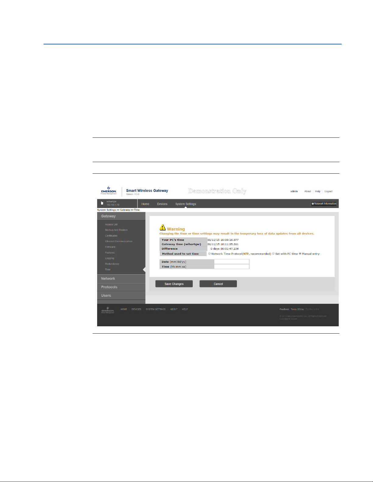
Time settings
The Gateway is the timekeeper for the WirelessHART network, so it is imperative that the
Gateway's time is accurate for timestamp data to be meaningful. Time settings can be found by
navigating to System Settings>Time.
4
Initial Connection
Page 11
Reference Manual
00809-0100-4052, Rev AA
Section 1: Initial Connection
April 2015
There are three ways to set the Gateway time:
1. Network Time Protocol (recommended).This option uses a Network Time Protocol
(NTP) server to slowly adjust the Gateway's time in order to match the time of the
control network. Enter the IP address for the NTP server and select the packet version
(1, 2, 3, or 4).
2. Set with PC Time. This option will match the Gateway's time to that of the PC/Laptop.
3. Manual Entry.This option allows the user to enter a specific date (MM:DD:YY) and time
(HH:MM:SS).
Note
Network Time Protocol (NTP) is recommended for the best network performance because it
always adjusts time to match the network time server.
Figure 1-1. Time Settings
Initial Connection
5
Page 12

Section 1: Initial Connection
April 2015
TCP/IP network settings
Use caution when making changes to the TCP/IP network settings. If they are lost or
improperly configured, it may be impossible to log into the Gateway. Contact the network
administrator for information on the proper TCP/IP network settings to apply
Prior to the gateway being installed and connected to a live control network, it should be
configured with an IP address, as well as other TCP/IP network settings.
Request the following configuration items from the network administrator:
Specify an IP address, or use a DHCP server
Hostname
Domain Name
IP address
Netmask
Gateway
Reference Manual
00809-0100-4052, Rev AA
Obtaining an IP address from a DHCP server is not recommended, since the Gateway operation
will be dependent on the availability of the DHCP server. For maximum gateway availability it is
best practice to specify an IP address.
To change the TCP/IP Network Settings:
1. Navigate to System Settings>Gateway>Ethernet Communication protocol.
2. Select Specify an IP address (recommended).
3. Enter the following:
Hostname
Domain Name
IP Address
Netmask
Gateway
4. Select Submit.
5. When prompted, click Restart apps.
6. Select YES to confirm restart.
7. Close the web browser.
Note
Once the IP Address of the Gateway has been changed, communications to the web interface
will be lost. Restart the web browser, then log back into the Gateway using the new IP address
and other TCP/IP network settings. The PC/Laptop TCP/IP network settings may need to be
changed.
6
Initial Connection
Page 13

Reference Manual
00809-0100-4052, Rev AA
Section 1: Initial Connection
April 2015
Figure 1-2. Ethernet Settings
Initial Connection
Quality of service
In order to enhance the data traffic from the WirelessHART radio to the network the Quality of
Service (QoS) option has been included in the Ethernet Protocol page to allow selection of a
specific traffic control mechanism based on the various manners increase network performance
within a more comprehensive network. There are twenty-one options to choose from
(drop-down menu) as listed and described below, these are the Differentiated Services Cope
Point (DSCP) codes as a standard embedded into network messages IP header:
Default: no specific traffic prioritization is selected
Assured forwarding (AF): this mechanism allows the data traffic to be prioritized based
on the required throughput, delay, jitter, loss or latency following an assured
forwarding per hop behavior. There are four AF Classes and each class has three drop
probabilities which are identified on the bits assignment at the IP header (first 6 bits
within Differentiated Services field)
Drop Class 1 Class 2 Class 3 Class 4
Low AF 11 AF 21 AF 31 AF 41
Medium AF 12 AF22 AF 32 AF 42
High AF13 AF 23 AF 33 AF 43
7
Page 14

Section 1: Initial Connection
April 2015
Class selector (CS): this mechanism allows for a selection of seven options which
prioritizes the data packets as per the option bits within the Type of Service (ToS) byte.
The combination of all three IP Precedence bits is used to adjust the IP packet
prioritization within the network.
P2 P1 P0 T2 T1 T0 CU1 CU0
001000 CS 1
010000 CS 2
011000 CS 3
100000 CS 4
101000 CS 5
110000 CS 6
111000 CS 7
Expedited forwarding: this mechanism is used when the data traffic is targeted to have
low delay, low jitter, low loss and low latency, hence prioritizing bandwidth to target a
“point-to-point” communication experience.
The recommended differentiated services setup are: AF41 (Assured Forwarding 41) or EF
(Expedited Forwarding). The AF41 shall be used whenever video related data is part of the
wireless solution and EF shall be used for any other solution which doesn't include video as part
of the package.
Reference Manual
00809-0100-4052, Rev AA
IP Precedence Delay, Throughput and Reliability Currently Unused
1.3.3 System backup
The Gateway has a System Backup and Restore feature that saves all user-configured data. It is
best practice that a System Backup be performed periodically throughout the installation and
configuration process.
1. Navigate to System Settings>Gateway>Backup And Restore>Save Backup.
2. Select Save Backup.
3. The Gateway collects the configuration date and when the file download pop up
appears, select Save.
4. Enter a save location and file name.
5. Select Save.
6. Select Return to form.
Note
System backup contains user passwords and keys used for encrypting communication. Store
downloaded system backups in a secure location.
8
Initial Connection
Page 15

Reference Manual
00809-0100-4052, Rev AA
Section 2 Software Setup
Overview . . . . . . . . . . . . . . . . . . . . . . . . . . . . . . . . . . . . . . . . . . . . . . . . . . . . . . . . . . . . . . . . . . page 9
System requirements . . . . . . . . . . . . . . . . . . . . . . . . . . . . . . . . . . . . . . . . . . . . . . . . . . . . . . . . page 9
Software installation . . . . . . . . . . . . . . . . . . . . . . . . . . . . . . . . . . . . . . . . . . . . . . . . . . . . . . . . page 10
Security setup utility . . . . . . . . . . . . . . . . . . . . . . . . . . . . . . . . . . . . . . . . . . . . . . . . . . . . . . . . page 10
Licensing and credits . . . . . . . . . . . . . . . . . . . . . . . . . . . . . . . . . . . . . . . . . . . . . . . . . . . . . . . . page 11
2.1 Overview
This section discusses the installation and setup of the optional software available for the Smart
Wireless Gateway. This software is not required for the wireless field network to operate;
however, it will aid in secure host integration as well as wireless field device configuration.
Additional system components may be installed depending on the current configuration of the
system.
Section 2: Software Setup
April 2015
2.2 System requirements
Table 2-1. PC Hardware
Minimum requirements Recommended requirements
Intel™ Core 2 Duo, 2.0 GHz Intel Core 2 Quad, 2.0 GHz or greater
1 GB Memory 3 GB Memory or Greater
1.5 GB free hard disk space 2 GB or more of free hard disk space
Note
Additional hard disk space is required for SNAP-ON
requirements are 1024 x 768 resolution and 16-bit color.
Table 2-2. Supported Operating Systems
Operating system Versio n
Microsoft® Windows™ XP Professional, Service Pack 3
Windows Server 2003 Standard, Service Pack 2
Windows Server 2003 R2 Standard, Service Pack 2
Windows Server 2008 Standard, Service Pack 2
Windows Server 2008 R2 Standard, Service Pack 1
Windows 7 Professional, Service Pack 1
Windows 7 Enterprise, Service Pack 1
™
applications. The minimum monitor
9Software Setup
Page 16

Section 2: Software Setup
April 2015
2.3 Software installation
The software can be obtained from Emerson during solution implementation. Depending on
the PC system configuration, installation may take 30-35 minutes. To install the software:
1. Exit/close all Windows programs, including any running in the background, such as
virus scan software.
2. Insert Disk 1 into the CD/DVD drive of the PC.
3. Follow the prompts.
Note
If the autorun function is disabled on the PC, or installation does not begin automatically,
double click D:\SETUP.EXE (where D is the CD/DVD drive on the PC) and click OK.
2.4 Security setup utility
The Security Setup Utility enables secure communications between the Gateway and host
system, asset management software, data historians, or other applications. This is done by
encrypting the standard data protocols (AMS
EtherNet/IP™, and OPC™) used by the Gateway and making them available through various
proxies within the Security Setup Utility. These proxies can function as a data server for other
applications on the control network. The Security Setup Utility can support multiple Gateways
at once and each proxy can support multiple client application connects.
Reference Manual
00809-0100-4052, Rev AA
®
Wireless Configurator, Modbus® TCP,
Note
OPC communications requires the use of the Security Setup Utility regardless of whether
encryption is required.
2.4.1 Setup
In the Security Setup Utility add a new proxy for each Gateway based on the communication
protocol that is being used. For example, add an OPC proxy for each Gateway that is
communicating OPC.
Use the following procedure to add a new proxy in the Security Setup Utility:
1. Open the Security Setup Utility.
2. Select EDIT>NEW, then select the type of new proxy to be added.
3. Right click on the new proxy entry and select Properties.
4. Enter the target Gateway's Hostname and IP Address.
5. Select OK.
6. Select FILE>SAVE.
7. When prompted for authentication, enter the admin password for the target Gateway.
8. Select OK.
9. Repeat steps 2-8 to added additional proxies.
10. Select FILE>EXIT to close the Security Setup Utility.
10
Software Setup
Page 17

Reference Manual
00809-0100-4052, Rev AA
Section 2: Software Setup
April 2015
During this process the Gateway will exchange security certificates (digital signatures) with the
proxy.
Figure 2-1. Security Setup Utility
2.5 Licensing and credits
The latest licensing agreements are included on each disk of the software pack.
“This product includes software developed by the OpenSSL Project for use in the OpenSSL
Toolkit. (http://www.openssl.org/)”
“This product includes software written by Eric Young (eay@cryptsoft.com)”.
Software Setup
11
Page 18

Section 2: Software Setup
April 2015
Reference Manual
00809-0100-4052, Rev AA
12
Software Setup
Page 19

Reference Manual
00809-0100-4052, Rev AA
Section 3 Host Integration
Overview . . . . . . . . . . . . . . . . . . . . . . . . . . . . . . . . . . . . . . . . . . . . . . . . . . . . . . . . . . . . . . . . . . page 13
Network architecture . . . . . . . . . . . . . . . . . . . . . . . . . . . . . . . . . . . . . . . . . . . . . . . . . . . . . . . page 13
Internal firewall . . . . . . . . . . . . . . . . . . . . . . . . . . . . . . . . . . . . . . . . . . . . . . . . . . . . . . . . . . . . . page 13
Internal firewall . . . . . . . . . . . . . . . . . . . . . . . . . . . . . . . . . . . . . . . . . . . . . . . . . . . . . . . . . . . . . page 13
Modbus . . . . . . . . . . . . . . . . . . . . . . . . . . . . . . . . . . . . . . . . . . . . . . . . . . . . . . . . . . . . . . . . . . . page 14
3.1 Overview
This section describes how to connect the Gateway to a host system and integrate data
gathered from the field device network. It covers network architectures, security, and data
mapping.
Section 3: Host Integration
April 2015
In accordance with Emerson WirelessHART
be connected to the host system via a LAN (Local Area Network) and not a WAN (Wide Area
Network).
3.2 Network architecture
Physical connection types are important when determining the network architecture and what
protocols can be used for integration. Ethernet is the main physical connection type. Emerson
provides all support to design, scope and commission the Smart Wireless Gateway 1552WU
into various types of hosts, please contact us for further information on this topic.
Ethernet
An Ethernet connection supports Modbus® TCP, OPC™, AMS® Wireless Configurator,
EtherNet/IP
directly to a control network using a network switch, router, or even via a wireless backhaul.
Often there are two networks for redundancy purposes.
™
, and HART® TCP protocols. Using this connection type, the Gateway is connected
3.3 Internal firewall
The Gateway supports an internal firewall that inspects both incoming and outgoing data
packets. TCP ports for communication protocols are user configurable, including user specified
port numbers and the ability to disable ports.
®
security guidelines, the Emerson Gateway should
Host Integration
The Gateway’s internal firewall settings can be found by navigating to System Settings>
Protocols>Protocols and Ports.
13
Page 20

Section 3: Host Integration
April 2015
Figure 3-1. Security Protocols Page (Internal Firewall)
Reference Manual
00809-0100-4052, Rev AA
3.4 Modbus
The Gateway supports Modbus TCP over Ethernet. It functions as a sub device on the Modbus
network and must be polled by a Modbus master or client (host system).
3.4.1 Communication settings
It is important that the Modbus communication settings in the Gateway match the setting in
the Modbus master or client. Please refer to host system documentation for more information
on how to configure these settings. The Modbus communication settings can be found by
navigating to System Settings>Protocols>Modbus.
14
Host Integration
Page 21

Reference Manual
00809-0100-4052, Rev AA
Figure 3-2. Modbus Communications Page
Section 3: Host Integration
April 2015
Single Modbus Address: When this option is selected, this address is used by the Gateway for
Modbus RTU communications (not applicable to the 1552WU Gateway).
Multiple Modbus Addresses: When this option is selected, a new column for address will
appear on the Modbus mapping page.
Modbus TCP Port: This is the TCP/IP port the Gateway uses for Modbus TCP (Ethernet). To
change TCP/IP port settings, see the Internal Firewall section for more details.
Baud Rate: The data rate or speed of serial communications. This setting is only required for
Modbus RTU (not applicable to the 1552WU Gateway).
Parity: This setting determines parity (none, even, or odd) to use for error checking purposes.
This setting is only required for Modbus RTU (not applicable to the 1552WU Gateway).
Stop Bits: This setting determines the number (1 or 2) of stop bits to use when ending a
message. This setting is only required for Modbus RTU (not applicable to the 1552WU
Gateway).
Response delay time (ms): This setting determines how long (ms) the Gateway waits before
responding to a Modbus request. This setting is only required for Modbus RTU (not applicable to
the 1552WU Gateway).
Host Integration
15
Page 22

Section 3: Host Integration
April 2015
Unmapped register read response: This is the value returned by the Gateway if the Modbus
master requests a register with no data assigned to it (empty register). It is recommended this
be set to zero fill to prevent errors.
Floating point representation: This setting determines if the Gateway uses floating point
values or integer values. There are three options for this setting:
Float: This option uses 32 bit floating point values.
Round: This option rounds the data value to the nearest whole number.
Scaled: This option uses scaled integers to offset negative values or increase decimal
Where:
y = Scaled integer returned by the Gateway
A = Gain for scaled integer value
x = Measured value from wireless field device
Reference Manual
00809-0100-4052, Rev AA
point resolution. The equation for scaled integers is:
y = Ax - (B - 32768)
B = Offset for scaled integer value
Use swapped floating point format: This setting switches which register is sent first for a
floating point value. This setting is only used for floating point values.
Incorporate value's associated status as error: This setting will cause the Gateway to report a
predetermined value when a communications or critical diagnostic error is received from the
wireless field device. The value is user configurable depending on which floating point
representation is chosen. See Value reported for error below.
Value reported for error (floating point): This setting determines what value is reported if the
wireless field device reports a failure or stops communicating to the Gateway. This setting is
used for floating point values. The choices are NaN (not a number), +Inf (positive infinity), -Inf
(negative infinity), or Other (user specified).
Value reported for error (rounded and native integer): This setting determines what value is
reported if the wireless field device reports a failure or stops communicating to the Gateway.
This setting is used for rounded or scaled integers. The choice is a user specified value between
-32768 and 65535.
Scaled floating point maximum integer value: This determines the maximum integer value
for the purpose scaling integers. 999-65534.
Use global scale gain and offset: This setting determines if a global gain and offset is applied
for scaled integers or if each value has a unique gain and offset. Unique gain and offsets are
found on the Modbus Mapping page.
16
Global scale gain: This value is multiplied to the data values for the purpose of scaling integers.
If global scaling is not selected, a gain value will be available for each separate data value on the
Modbus Mapping page.
Global scale offset: This value is added to the data values for the purpose of scaling integers. If
global scaling is not selected, an offset value will be available for each separate data value on the
Modbus Mapping page.
Host Integration
Page 23

Reference Manual
00809-0100-4052, Rev AA
3.4.2 Register mapping
Register mapping is the process of assigning data points from wireless field devices to Modbus
registers. These registers can then be read by a Modbus master or client. Modbus register
mapping can be found by navigating to System Settings>Protocols>Modbus.
Figure 3-3. Modbus Register Map Page
Section 3: Host Integration
April 2015
Host Integration
To add a new data point to the Modbus register map:
1. Click Add New Entry.
2. Complete all of the table entries for the new data point (note that the entry columns
may vary based on the Modbus communications settings).
3. Repeat for each new data point.
4. Click Submit.
5. When changes have been accepted, click Return to form.
Address: This is the Modbus RTU address used by the Gateway for this data point. It is possible
to group data points assigning them the same address (i.e. all data points from the same
process unit can have the same address). This column only appears if Multiple Modbus
Addresses is selected on the Modbus Communications page.
Register: This is the Modbus register number used for this data value. Modbus registers hold
two bytes (16 bits) of information; therefore 32 bit floats and integers require two Modbus
17
Page 24

Section 3: Host Integration
April 2015
registers. Each data point needs a unique Modbus register number, unless they are assigned
different addresses. Register numbers 0-19999 are reserved for Boolean (bit, coil, binary, etc…)
values. Register numbers 20000+ are reserved for floating point or integer values.
Point Name: This is a two part name for the data point. The first part is the HART Tag of the
wireless field device which is producing the data. The second part is the parameter of the
wireless field device.
Point Name is entered as <HART Tag.PARAMETER>. Point Name can be entered using the list of
values (…) or manually entered. The following table gives a list of standard device parameters
which may be considered for Modbus register mapping.
Table 3-1. Standard Device Parameters for Modbus Register Mapping
Parameter Description Data type
PV Primary Variable 32-bit float
SV Secondary Variable 32-bit float
TV Tertiary Variable 32-bit float
QV Tertiary Variable 32-bit float
RELIABILITY A measure of connectivity to the Gateway 32-bit float
ONLINE Wireless communications status Boolean
PV_HEALTHY Health status for PV Boolean
SV_HEALTHY Health status for SV Boolean
TV_HEALTHY Health status for TV Boolean
QV_HEALTHY Health status for QV Boolean
Reference Manual
00809-0100-4052, Rev AA
PV, SV, TV, and QV (dynamic variables) will vary by device type. Please refer to the device's
documentation for more information on what value is represented by each dynamic variable.
RELIABILITY and ONLINE relate to wireless communications. RELIABILITY is the percentage of
messages received from the wireless field device. ONLINE is a true/false indication of whether
the device is communicating on the wireless network.
**_HEALTHY parameters are a true/false indication of the health of a particular variable (** =
dynamic variable - PV, SV, etc…). These parameters incorporate critical diagnostics from the
wireless field device as well as communication status.
Note
The **_HEALTHY parameters are a great indication of the health and communications status of
the data values.
State (state value): The value of a data point which drives a Modbus output of 1. For example, if
a data point is reported as either True or False, a state value of True will report a 1 for True and 0
for False. A state of False will report a 0 for True and a 1 for False. State is only required for
register numbers 0-19999 (Boolean, bit, coil, binary, etc…).
Invert: This check box will invert the Modbus output from a 1 to a 0 or a 0 to a 1. Invert is only
used for Boolean values using register numbers 0-19999.
Gain: This value is multiplied to the data value for the purpose of scaling integers. Gain is only
required if scaled is chosen on the Modbus communications page and globe gain and offset is
not chosen.
18
Host Integration
Page 25

Reference Manual
00809-0100-4052, Rev AA
Offset: This value is added to the data value for the purpose of scaling integers. Offset is only
required if scaled is chosen on the Modbus communications page and globe gain and offset is
not chosen.
Predefined Modbus registers
In addition to user configurable parameters, the Gateway also supports a list of predefined
Modbus registers with diagnostics and test parameters. The following table is a list of the
predefined Modbus registers.
Table 3-2. Predefined Modbus Registers with Diagnostics and Test Parameters
Section 3: Host Integration
April 2015
Description Register Data type
Current Year (1) 49001 32-bit int
Current Month (1) 49002 32-bit int
Current Day (1) 49003 32-bit int
Current Hour (1) 49004 32-bit int
Current Minute (1) 49005 32-bit int
Current Second (1) 49006 32-bit int
Messages Received 49007 32-bit int
Corrupt Messages Received 49008 32-bit int
Messages Sent With Exception 49009 32-bit int
Messages Sent Count 49010 32-bit int
Valid Messages Ignored 49011 32-bit int
Constant Float 12345.0 49012 32 float
SYSTEM_DIAG.HART_DEVICES 49014 32-bit int
SYSTEM_DIAG.ADDITIONAL_STATUS_0 49015 8-bit unsigned int
SYSTEM_DIAG.ADDITIONAL_STATUS_1 49016 8-bit unsigned int
SYSTEM_DIAG.ADDITIONAL_STATUS_2 49017 8-bit unsigned int
SYSTEM_DIAG.ADDITIONAL_STATUS_3 49018 8-bit unsigned int
SYSTEM_DIAG.ADDITIONAL_STATUS_4 49019 8-bit unsigned int
SYSTEM_DIAG.ADDITIONAL_STATUS_5 49020 8-bit unsigned int
SYSTEM_DIAG.ADDITIONAL_STATUS_6 49021 8-bit unsigned int
SYSTEM_DIAG.ADDITIONAL_STATUS_7 49022 8-bit unsigned int
SYSTEM_DIAG.ADDITIONAL_STATUS_8 49023 8-bit unsigned int
SYSTEM_DIAG.ADDITIONAL_STATUS_9 49024 8-bit unsigned int
SYSTEM_DIAG.ADDITIONAL_STATUS_10 49025 8-bit unsigned int
SYSTEM_DIAG.ADDITIONAL_STATUS_11 49026 8-bit unsigned int
SYSTEM_DIAG.ADDITIONAL_STATUS_12 49027 8-bit unsigned int
SYSTEM_DIAG.UNREACHABLE 49028 32-bit int
SYSTEM_DIAG.UPTIME 49029 32-bit int
SYSTEM_DIAG.TEST_BOOLEAN 49031 Boolean
SYSTEM_DIAG.TEST_BYTE 49032 8-bit int
SYSTEM_DIAG.TEST_UNSIGNED_BYTE 49033 8-bit unsigned int
SYSTEM_DIAG.TEST_SHORT 49034 16-bit int
SYSTEM_DIAG.TEST_UNSIGNED_SHORT 49035 16-bit unsigned int
SYSTEM_DIAG.TEST_INT 49036 32-bit int
SYSTEM_DIAG.TEST_UNSIGNED_INT 49038 32-bit unsigned int
SYSTEM_DIAG.TEST_FLOAT 49040 32-bit float
Host Integration
19
Page 26

Section 3: Host Integration
April 2015
Reference Manual
00809-0100-4052, Rev AA
20
Host Integration
Page 27

Reference Manual
00809-0100-4052, Rev AA
Section 4 DeltaV™ Ready
Overview . . . . . . . . . . . . . . . . . . . . . . . . . . . . . . . . . . . . . . . . . . . . . . . . . . . . . . . . . . . . . . . . . . page 21
Latency considerations in control logic design and operation . . . . . . . . . . . . . . . . . . . . . page 21
Requirements . . . . . . . . . . . . . . . . . . . . . . . . . . . . . . . . . . . . . . . . . . . . . . . . . . . . . . . . . . . . . . page 21
Setup . . . . . . . . . . . . . . . . . . . . . . . . . . . . . . . . . . . . . . . . . . . . . . . . . . . . . . . . . . . . . . . . . . . . . . page 22
4.1 Overview
Native integration with DeltaV enables the Smart Wireless Gateway to be auto-sensed and easily
commissioned for seamless integration with all DeltaV applications: Explorer, Diagnostics, and
Control Studio. WirelessHART
then reconciled through DeltaV Explorer and assigned to analog channels through drag and
drop assignment.
®
devices can be easily added to the wireless field network and
Section 4: DeltaV Ready
April 2015
4.2 Latency considerations in control logic design and operation
Since the DeltaV wireless I/O scanner software requests updates for 1/5 of the devices each
second, DeltaV receives updates on a particular field device once every 5 seconds. That is not
necessarily synchronized with the update rate of the field device. Also, there is some latency
between when the field device takes a process sample and when it is permitted to pass its value
onto the wireless network. Status update responses can also increase latency in some instances.
So for example, if a device updates once every 8 seconds, and wireless network latency is 2
seconds, the amount of time that could pass between when an event occurred in the field and
before it is available to the DeltaV I/O bus is between zero and 15 (8+2+5) seconds. The update
period of the DeltaV control module should be added to that total to determine the range of
latencies before an event in the field can be acted upon by the control system.
Operators should be made aware that the update rate of wireless measurements on operator
screens are somewhat slower than those from wired devices. For example, if the operator
initiates a valve movement, it can be 5-15 seconds before confirming feedback appears on the
operator screen. Any control logic designed along the same principles should also take the
update rates and latencies into account as well.
4.3 Requirements
™
Ready
DeltaV
Version 10.3 or newer.
Smart Wireless Gateway
DeltaV Ready option
21DeltaV
Page 28

Section 4: DeltaV Ready
April 2015
4.4 Setup
Out of the box the Smart Wireless Gateway is pre-configured for use on the DeltaV control
network. In the DeltaV Explore application, the Gateway will automatically appear in the
Decommissioned Nodes folder.
To setup a wireless network will require 3 steps:
1. Commission the Gateway.
2. Assign wireless device tags.
3. Assign Gateway to controller and download.
Figure 4-1. Decommissioned Nodes Folder within DeltaV Explorer
Reference Manual
00809-0100-4052, Rev AA
22
Commission the Gateway using the following procedure:
1. Select START>PROGRAMS>DELTAV>ENGINEERING> DELTAV EXPLORE to launch the
DeltaV Explorer application.
2. Expand the folder SYSTEM CONFIGURATION >PHYSICAL
NETWORK>DECOMMISSIONED NODES.
3. Right click on the Smart Wireless Gateway and select Commission.
4. Enter a name for the Gateway and select OK.
5. Select YES when prompted to Auto-Sense Wireless Gateway.
At this time the Reconcile I/O window will appear. The purpose of this screen is to assign
WirelessHART devices to DeltaV I/O channel. This allows the wireless device to be referenced in
other DeltaV applications like Control Studio.
DeltaV™ Ready
Page 29

Reference Manual
00809-0100-4052, Rev AA
Figure 4-2. Assign WirelessHART Devices to DeltaV I/O Channel
Section 4: DeltaV Ready
April 2015
Assign wireless device tags using the following procedure:
1. Drag and Drop WirelessHART device from the Unassigned Wireless HART Devices: list to
the Channels: list.
2. Repeat this process for each wireless device until all have been assigned.
3. Select OK to continue.
Next the Gateway will need to be assigned to a DeltaV Controller and download all. Assign and
download the Gateway using the following procedure:
1. Right click on the Gateway and select Assign…
2. Use the browse window and select the desired controller.
3. Select OK to close the assignment window.
4. Right click on the Gateway and select Download.
5. Follow the download dialog.
6. Select OK to close the download window.
DeltaV™ Ready
23
Page 30

Section 4: DeltaV Ready
April 2015
Figure 4-3. Gateway Context Menu (Right Click)
Now the Gateway and wireless devices are fully commissioned and available to use in other
DeltaV applications. When new devices are added to the wireless network, they will need to be
assigned to DeltaV channels through the reconcile process (right click on Gateway and select
configure IO).
Reference Manual
00809-0100-4052, Rev AA
Note
Logging in to the Gateway is not possible using the default TCP/IP network setting. If the
Gateway is decommissioned, use an IP address 10.5.255.254. If the Gateway is commissioned,
right click on the Gateway in DeltaV Explore and select Wireless Gateway Web Interface.
24
DeltaV™ Ready
Page 31

Reference Manual
00809-0100-4052, Rev AA
Section 5 Redundancy
Overview . . . . . . . . . . . . . . . . . . . . . . . . . . . . . . . . . . . . . . . . . . . . . . . . . . . . . . . . . . . . . . . . . . page 25
Requirements . . . . . . . . . . . . . . . . . . . . . . . . . . . . . . . . . . . . . . . . . . . . . . . . . . . . . . . . . . . . . . page 25
Setup . . . . . . . . . . . . . . . . . . . . . . . . . . . . . . . . . . . . . . . . . . . . . . . . . . . . . . . . . . . . . . . . . . . . . . page 26
Mounting and connections . . . . . . . . . . . . . . . . . . . . . . . . . . . . . . . . . . . . . . . . . . . . . . . . . . . page 28
Diagnostics . . . . . . . . . . . . . . . . . . . . . . . . . . . . . . . . . . . . . . . . . . . . . . . . . . . . . . . . . . . . . . . . page 28
Gateway replacement . . . . . . . . . . . . . . . . . . . . . . . . . . . . . . . . . . . . . . . . . . . . . . . . . . . . . . . page 30
5.1 Overview
Redundancy for the Smart Wireless Gateway increases the availability of the wireless field
network by providing two sets of physical hardware which operate as a single Gateway system.
This section covers setup and installation of a redundant Gateway system. It also covers
diagnostics and integration to help monitor the health of the redundant Gateway system.
Section 5: Redundancy
April 2015
Where to mount the respective antennas
Illustration of maximum redundancy including dual switch and UPS
Understanding how the failover works and experience to expect
How to leverage the multi-master capability for Modbus integrations
5.2 Requirements
Smart Wireless Gateway
Firmware Version 4.4.30 or greater is recommended
RD option for Gateway Redundancy
Static IP Address
Must have matching output protocols (e.g. Modbus
The Redundancy feature is not supported by Wireless Gateways with the DeltaV
feature enabled.
Host system
®
or OPC™) on each Gateway.
™
Ready
Redundancy
Ethernet connection for Modbus TCP or OPC DA communications
25
Page 32

Section 5: Redundancy
April 2015
5.3 Setup
When configuring redundant Smart Wireless Gateways, it is only necessary to configure one
system. The other Gateway will be configured automatically when it is paired with the first
Gateway.
Choose one Gateway as the starter Gateway. For the purposes of this document, it will be
referred to as Gateway A. The other Gateway will be referred to as Gateway B. To configure
redundancy system settings:
1. Connect a PC/laptop to the Ethernet 1 port on Gateway A.
2. Log in using the admin user account.
3. Navigate to System Settings>Gateway>Redundancy.
4. Gateway A's factory serial number will be assigned to Gateway A.
5. Gateway B's factory serial number will be assigned to Gateway B.
The Gateway names will be used in diagnostic messages and host system integration to help
identity each Gateway. It is recommended that these names be marked on each physical
Gateway, in addition to the configuration settings.
Reference Manual
00809-0100-4052, Rev AA
Selecting left or right for Gateway A is for visualization purposes only. It has no effect on
performance or functionality.
Figure 5-1. Redundancy System Settings (Setup>Redundancy)
26
After the redundancy system settings have been configured, the two Gateways must be
connected and undergo a pairing process.
Redundancy
Page 33

Reference Manual
A
B
C
D
E
00809-0100-4052, Rev AA
To pair both Gateways and form a redundant system:
1. Connect a PC/laptop to the primary Ethernet port on Gateway A.
2. Log in using the admin user account.
3. Navigate to Diagnostics>Advanced>Redundancy Status.
4. Connect the secondary Ethernet port on Gateway A to the secondary Ethernet port on
5. A dialog will appear on the page, select Form redundant pair.
6. Wait for the Pairing to redundant peer status to turn green.
7. Select Return to page.
Figure 5-2. Redundancy Setup Connections
Section 5: Redundancy
April 2015
Gateway B (see Figure 5-2 on page 27, Redundancy Setup Connections).
A. PC/laptop D. Primary Ethernet
B. Gateway A E. Secondary Ethernet
C. Gateway B
Once the Gateways have finished the pairing process, Gateway A will appear as the current
active Gateway on the left hand side and Gateway B will be the standby Gateway on the right
(note that left/right hand appearance can be changed on the Redundancy System Settings
page). If significant configuration changes need to be downloaded to the standby Gateway, it
may temporarily go offline shortly after the pair process is complete. This is expected behavior
and does not represent instability in the system.
Redundancy
27
Page 34

Section 5: Redundancy
April 2015
5.4 Mounting and connections
Redundant Gateways follow similar mounting and connection practices as a standalone
Gateway. Refer to Section 3: Host Integration for more information. In addition to the standard
practices, the following considerations should be taken when installing redundant Gateways.
Mounting
The redundant Gateways should be mounted in a location that allows convenient access to the
process control network as well and provides good coverage for the wireless field network.
The redundant Gateway antennas should be mounted at the same height and be spaced
between 3 ft to 9 ft (1m to 3m) horizontally. This is to ensure that they provide identical
coverage for the wireless field network and to help eliminate coverage gap in the event of a
switch over.
Ethernet
An Ethernet connection to the host system will support Modbus TCP, OPC, AMS Wireless
Configurator, and HART IP protocols. When using this architecture, connect the secondary
Ethernet port on Gateway A directly to the secondary Ethernet port on Gateway B. Then
connect the primary Ethernet ports for both Gateways to a process control network using separate/redundant network switches.
Reference Manual
00809-0100-4052, Rev AA
Note
The primary Ethernet port for each Gateway should be connected to separate network switches
on the same process control network. Consult a control system administrator for more details
about available redundant network switches.
Power
Power for the redundant Gateways should be applied after all primary and secondary Ethernet
and RS-485 connections have been made. Using separate uninterruptable power supplies (UPS)
is recommended to ensure availability of the redundant Gateway system.
5.5 Diagnostics
The redundant system will perform many diagnostic checks to verify the health and
connectivity of the system. This diagnostics information can be found by navigating to System
Settings>Gateway>Redundancy Status.
28
Redundancy
Page 35

Reference Manual
00809-0100-4052, Rev AA
Figure 5-3. Redundancy Status (System Settings>Gateway>Redundancy Status)
Section 5: Redundancy
April 2015
These diagnostics can also be mapped to Modbus registers or OPC tags. The following table
covers what diagnostics are included on the Redundancy Status page as well as how they can be
mapped as parameters in Modbus or OPC.
Table 5-1. Redundancy Diagnostics
Parameter Description Data type
REDUNDANT_HEALTHY
RF_COVERAGE_FAILURE
REDUNDANT_A_ONLINE Operational status of Gateway A Boolean
REDUNDANT_A_MASTER
REDUNDANT_A_PING
REDUNDANT_A_ETH0
REDUNDANT_B_ONLINE Operational status of Gateway B Boolean
REDUNDANT_B_MASTER
REDUNDANT_B_PING
REDUNDANT_B_ETH0
Overall redundancy status indicating
the system is ready for a switch-over
Check to verify that both Gateways have
the same RF coverage of the wireless
field network
Indication if Gateway A is the active
System
Indication if Gateway A is able to ping
designated host IP address
Electrical connection status of the
primary Ethernet port for Gateway A
Indication if Gateway B is the active
system
Indication if Gateway B is able to ping
designated host IP address
Electrical connection status of the
primary Ethernet port for Gateway A
Boolean
Boolean
Boolean
Boolean
8-bit unsigned int
Boolean
Boolean
8-bit unsigned int
Redundancy
In addition to the redundancy diagnostics, an additional check may be configured to test
network connectivity to a host system or other application. The redundant system will use this
check to determine the best connectivity option and which Gateway should be set to the active
Gateway.
29
Page 36

Section 5: Redundancy
April 2015
To configure network connectivity check:
1. Navigate to System Settings>Gateway>Ethernet Communication.
2. Enter the host system IP address in the Check Network Connectivity IP Address field.
3. Select Submit.
Figure 5-4. Network Connectivity Check (System Settings>Gateway>Ethernet
Reference Manual
00809-0100-4052, Rev AA
Communication)
5.6 Gateway replacement
When replacing or reintroducing a Gateway in a redundant system, always connect both the
primary and secondary Ethernet connections before powering the standby Gateway. If the
Gateway is being reintroduced (i.e. it was a part of the original redundant system), it will
automatically rejoin the redundant system. If the Gateway is new or has been set to default
configuration, it will need to be paired to the current active Gateway. Navigate to System Set-
tings>Gateway>Redundancy and follow the recommended actions on that page or follow the
procedure above to pair Gateways and form a redundant system.
30
Redundancy
Page 37

Reference Manual
00809-0100-4052, Rev AA
Section 6 Wi-Fi Connectivity
Overview . . . . . . . . . . . . . . . . . . . . . . . . . . . . . . . . . . . . . . . . . . . . . . . . . . . . . . . . . . . . . . . . . . page 31
Wi-Fi architecture . . . . . . . . . . . . . . . . . . . . . . . . . . . . . . . . . . . . . . . . . . . . . . . . . . . . . . . . . . . page 31
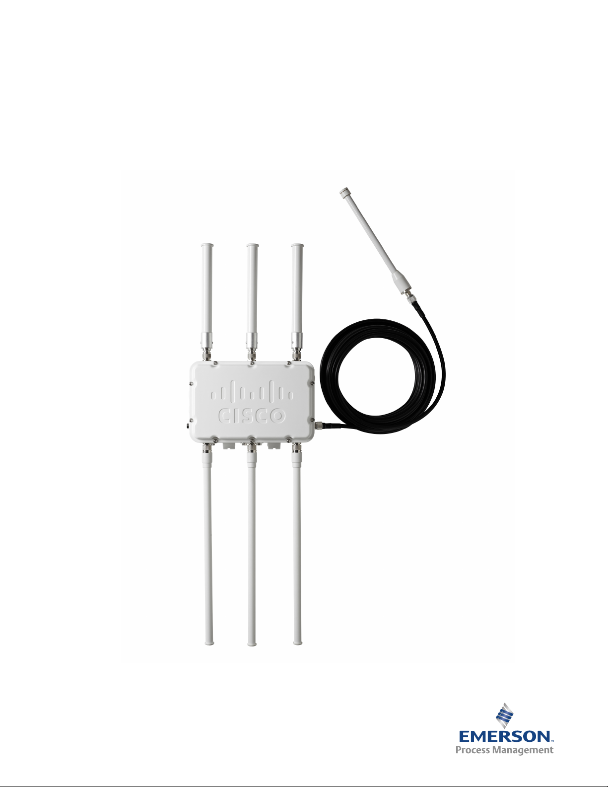
6.1 Overview
The Smart Wireless Gateway 1552WU also handles Wi-Fi connections based on IEEE802.11
standard, and it has two radios for this specific connectivity:
2.4GHz radio with three external antennas dedicated for local connection to client units
which are designed to run each of the various Wi-Fi solutions described on the Wireless
Plant Network solutions portfolio
5GHz radio with also three external antennas dedicated for the wireless backhaul.
Section 6: Wi-Fi Connectivity
April 2015
This section presents an overview of this connectivity for proper usage. It's important to
emphasize that professional services from Emerson or its Local Business Partner are required to
scope, design and commission the solution.
6.2 Wi-Fi architecture
The Smart Wireless Gateway 1552WU must be installed as per the recommendations described
on the Cisco Aironet 1550 Series for Hazardous Locations Installation Guide.
The 1552WU can be configured as a Root Access Point (RAP) as well as a Mesh Access Point
(MAP). These two roles basically describe the Wi-Fi access point behavior considering a network
with several units:
The RAP is normally the first access point of the network and is hardwired (Ethernet
RJ45 port) to the physical network, it can also be a minimum setup for a hot-spot
architecture where the access points won't communicate to each other, but simply
provide a local Wi-Fi coverage for clients accessing the physical network
The MAP role is designed to interconnect multiple access points following a mesh type
topology enhancing the backhaul capabilities.
For all conditions the 1552WU will always require a Wireless LAN Controller (WLC) which is the
responsible to control the Wi-Fi network including routes, data traffic, transmit power control,
etc. whereas the WLC is a mandatory requirement for any 1552WU installation. The Figure 6-1 is
a sample architecture that shows all various connections we can have considering the WLC, MAP
& RAP roles for the access points, and also highlighting the mix of Smart Wireless Gateway
1552WU and Cisco 1550 Series access points.
Wi-Fi Connectivity
31
Page 38

Section 6: Wi-Fi Connectivity
April 2015
Figure 6-1. Sample Wireless Architecture Showing Possible Connections
Reference Manual
00809-0100-4052, Rev AA
The Wireless LAN Controller is also chosen and setup based on the number of access points
included in the final architecture. The architecture is scalable and is completely controlled by
the WLC. Other network equipment can be included in the architecture to add security (e.g.:
firewalls) or even extra connectivity on the physical network (network switches, etc.).
Please contact your local Emerson contact for more information on the design of Wi-Fi
solutions.
32
Wi-Fi Connectivity
Page 39

Page 40

Rosemount World Headquarters
Emerson Process Management
6021 Innovation Blvd
Shakopee, MN 55379, USA
+1 800 999 9307 or +1 952 906 8888
+1 952 949 7001
RFQ.RMD-RCC@EmersonProcess.com
North America Regional Office
Emerson Process Management
8200 Market Blvd.
Chanhassen, MN 55317, USA
+1 800 999 9307 or +1 952 906 8888
+1 952 949 7001
RMT-NA.RCCRFQ@Emerson.com
Latin America Regional Office
Emerson Process Management
1300 Concord Terrace, Suite 400
Sunrise, Florida, 33323, USA
+1 954 846 5030
+1 954 846 5121
RFQ.RMD-RCC@EmersonProcess.com
Reference Manual
00809-0100-4052, Rev AA
April 2015
Europe Regional Office
Emerson Process Management Europe GmbH
Neuhofstrasse 19a P.O. Box 1046
CH 6340 Baar
Switzerland
+41 (0) 41 768 6111
+41 (0) 41 768 6300
RFQ.RMD-RCC@EmersonProcess.com
Asia Pacific Regional Office
Emerson Process Management Asia Pacific Pte Ltd
1 Pandan Crescent
Singapore 128461
+65 6777 8211
+65 6777 0947
Enquiries@AP.EmersonProcess.com
Middle East and Africa Regional Office
Emerson Process Management
Emerson FZE P.O. Box 17033,
Jebel Ali Free Zone - South 2
Dubai, United Arab Emirates
+971 4 8118100
+971 4 8865465
RFQ.RMTMEA@Emerson.com
Standard Terms and Conditions of Sale can be found at www.rosemount.com/terms_of_sale.
AMS, and the Emerson logo are registered trademarks and/or service marks of Emerson Electric Co.
DeltaV and SNAP-ON are trademarks of Emerson Electrical Co.
Rosemount and the Rosemount logotype are registered trademarks of Rosemount
Inc.
OUNDATION fieldbus, HART and WirelessHART are registered trademarks of Field-
F
Comm Group.
Microsoft is a registered trademark of Microsoft Corporation in the United States
and other countries.
Modbus is a registered trademark of Modicon, Inc.
Mozilla Firefox is a registered trademark of The Mozilla Foundation.
EtherNet/IP is a trademark of ControlNet International under license by ODVA.
Intel is a trademark of Intel Corporation in the U.S. and/or other countries.
Windows is a trademark of Microsoft Corporation in the United States and other
countries.
All other marks are the property of their respective owners.
© 2015 Rosemount, Inc. All rights reserved.
 Loading...