

Page 1
Reference Manual
00809-0100-4388, Rev BA
January 2008
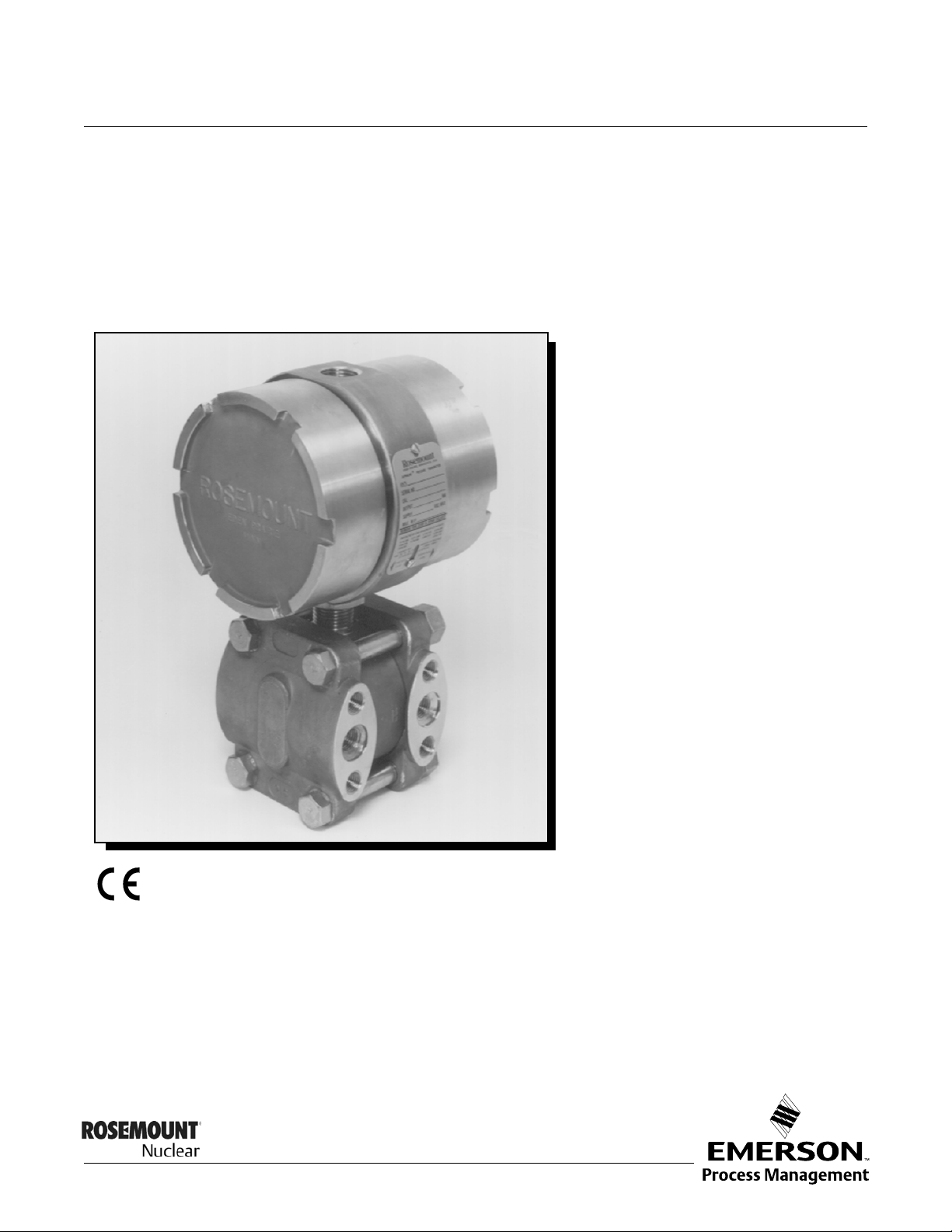
Rosemount 1153 Series D
Alphaline® Nuclear Pressure Transmitter
www.rosemountnuclear.com
Page 2

IMPOR TANT NOTICE -- ERRATA
Model 1153 Series D Product Manual 00809-0100-4388 Rev BA (January 2008)
Affected
No.
Pages
1 6-8
Process Flange –CF3M (Cast version of 316L SST)
Description of Change
Drain/Vent Valves –316L SST
Process Connections – 3/8-inch Swagelok compression fitting, 316L SST (1/4-18
NPT optional)
2 3-8 Change the first paragraph on the page to read as follows:
”Damping electronics are available as an option. Transmitters with standard
electronics can be retrofitted with the adjustable damping feature by changing out
both the amplifier board and the calibration board. Please reference Table 6-2
(Rosemount 1153 Series D Spare Parts List) for the applicable part numbers.”
Effect.
Date
10/21/09
4/13/12
3 6-11 Table 6-2,”Rosemount 1153 Series D Spare Parts List”, in all locations the
following part numbers are updated:
Amplifier Circuit Board, Output Code R:
”01154-0001-0005” is replaced by ”01154-0153-0001”
Amplifier Circuit Board with Damping, Output Code R:
”01154-0021-0004” is replaced by ”01154-0156-0001”
Amplifier Circuit Board, Output Code R, N0026:
”01154-0001-0006” is replace by ”01154-0153-0002”
(5)
Sensor Module, 316 SST
0-5/30 inH
O: ”01153-0320-0232” is replaced by ”01153-5320-0232”
2
:
”01153-0320-0132” is replaced by ”01153-5320-0132”
0-25/150 inH
O: ”01153-0320-0242” is replaced by ”01153-5320-0242”
2
”01153-0320-0342” is replaced by ”01153-5320-0342”
”01153-0320-0142” is replaced by ”01153-5320-0142”
0-125/750 inH
O: ”01153-0320-0252” is replaced by ”01153-5320-0252”
2
”01153-0320-0352” is replaced by ”01153-5320-0352”
”01153-0320-0152” is replaced by ”01153-5320-0152”
”01153-0320-0052” is replaced by ”01153-5320-0052”
0-17/100 psi: ”01153-0320-0262” is replaced by ”01153-5320-0262”
”01153-0320-0362” is replaced by ”01153-5320-0362”
”01153-0320-0162” is replaced by ”01153-5320-0162”
”01153-0320-0062” is replaced by ”01153-5320-0062”
0-50/300 psi: ”01153-0320-0272” is replaced by ”01153-5320-0272”
”01153-0320-0372” is replaced by ”01153-5320-0372”
”01153-0320-0172” is replaced by ”01153-5320-0172”
”01153-0320-0072” is replaced by ”01153-5320-0072”
0-170/1,000 psi: ”01153-0320-0282” is replaced by ”01153-5320-0282”
”01153-0320-0182” is replaced by ”01153-5320-0182”
”01153-0320-0082” is replaced by ”01153-5320-0082”
0-500/3,000 psi: ”01153-0320-0192” is replaced by ”01153-5320-0192”
0-1,000/4,000 psi: ”01153-0320-0102” is replaced by ”01153-5320-0102”
4 6-12 Table 6-2,”Rosemount 1153 Series D Spare Parts List”, the table footnotes are
updated to add note (5) which will read as follows:
4/13/12
4/13/12
(5) IMPORTANT NOTICE: To maintain a transmitter’s qualified configuration,
when purchasing or installing a new Sensor Module, Rosemount
Qualification report D2011019 must be carefully reviewed to verify that the
Sensor Module to be installed and the associated Amplifier Circuit Board in a
given transmitter is a qualified configuration. As detailed in the referenced
report, not all Sensor Module part numbers are considered qualified in conjunction
with certain Amplifier Circuit Boards.
Page 3

Reference Manual
Alphaline, Rosemount and the Rosemount logotype are registered trademarks of Rosemount Inc.
␦-Cell is a trademark of Rosemount Inc.
D.C. 55 is a registered trademarks of Dow Corning.
Loctite is a registered trademark of Henkel KGaA Corporation.
Grafoil is a trademark of Union Carbide Corp.
Swagelok is a registered trademark of Swagelok Co.
Lubri-Bond is a registered trademark of E/M Corporation.
Cover Photo: 1153-001AB
Rosemount Nuclear Instruments, Inc. satisfies all obligations coming
from legislation to harmonize product requirements in the European
Union.
00809-0100-4388, Rev BA
January 2008
Rosemount 1153 Series D
Rosemount 1153 Series D
Alphaline
®
Pressure
Transmitters
NOTICE
Read this manual before working with the product. For personal and system safety, and for
optimum product performance, make sure you thoroughly understand the contents before
installing, using, or maintaining this product.
For equipment service needs outside the United States, contact the nearest Rosemount
representative.
Within the United States, the North American Response Center is at your service 24 hours
a day, and is a single-point contact for all Rosemount equipment service needs. If at any
time you are not sure what to do, you have a question about using the product, or you have
a service or support request, call the center toll free at 1-800-654-RSMT (7768). This
contact is your fastest link to quick and complete answers about any Rosemount group,
product, or service.
www.rosemountnuclear.com
Page 4

Reference Manual
00809-0100-4388, Rev BA
Rosemount 1153 Series D
January 2008
Rosemount Nuclear Instruments, Inc. Warranty and
Limitations of Remedy
The warranty and limitations of remedy applicable to this Rosemount equipment are as stated on the reverse of the
current Rosemount quotation and customer acknowledgment forms.
RETURN OF MATERIAL
Authorization for return is required from Rosemount Nuclear Instruments, Inc. prior to shipment. Contact Rosemount Nuclear Instruments,
Inc. (1-952-949-5210) for details on obtaining Return Material Authorization (RMA). Rosemount Nuclear Instruments will not accept
any returned material without a Returned Material Authorization. Material returned without authorization is subject to return to
customer.
Material returned for repair, whether in or out of warranty, should be shipped prepaid to:
Rosemount Nuclear Instruments, Inc.
8200 Market Blvd.
Chanhassen, MN 55317
USA
IMPORTANT
The Rosemount 1153 Series D Pressure Transmitter is designed for Nuclear Class IE usage, has been tested per IEEE Std 323-1974 and
344-1975 as defined in the Qualifications Test Report D8300040, and is manufactured to the requirements of NQA-1; 10CFR50, Appendix
B quality assurance programs; and 10CFR Part 21. During qualification testing, interfaces were defined between the transmitter and its
environment that are essential to meeting IEEE Std 323-1974 requirements. To ensure compliance with 10CFR Part 21, the transmitter
must comply with the requirements herein throughout its installation, operation, and maintenance. It is incumbent upon the user to ensure
that the Rosemount Nuclear Instruments, Inc. component traceability program is continued throughout the qualified life of the transmitter.
In order to maintain the qualified life status of the transmitter, the essential environmental interfaces must not be compromised.
Performance of any operations on the transmitter other than those specifically authorized in this manual has the potential for
compromising an essential environmental interface.
Where the manual uses the terms requirements, mandatory, must, or required, the instructions so referenced must be carefully followed.
Rosemount Nuclear Instruments, Inc. expressly disclaims all responsibility and liability for transmitters for which the foregoing has not
been complied with by the user.
ii
Page 5

Reference Manual
00809-0100-4388, Rev BA
January 2008
Rosemount 1153 Series D
Revision Status
Changes From 1999 to January 2008
Page (Old) Page (New) Changes
Cover Cover Document revision date change from May 1999 to January 2008, rev from AA to BA
Inside cover, i, ii,
5-9 & back cover
3-7, 6-9 & 6-10 3-8, 6-11 & 6-12 Include errata sheet information on circuit board number changes:
Throughout Throughout References to Fisher-Rosemount were changed to Emerson Process Management
i, back cover Cover, i, ii & back
- Cover, i, back page Added reference to European Union product requirement (CE)
2-1,3-1,4-1,5-1,6-1 2-1,3-1,4-1,5-1,6-1 Added table of contents to each section
2-2 2-2 Updated reference to Swagelok catalog and added web address, removed street
2-2 2-2 Removed word “process” from sentence indicating user assumes responsibility for
2-4 2-4 Rearranged wording on shielded cable, removed reference to 353C
2-6 & 2-7 2-7 & 2-8 Added word ‘nominal’ to Notes in drawings. Changed significant digits to conform to
5-6 & 6-10 5-6 & 6-12 Inserted information on the spare parts kit for bolts and nuts for process flange
6-2 6-2 Changed ISO 9001 to ISO 9001:2000
6-10 6-12 Replaced pipe mount bracket kit (adapters) P/N 01154-0038-0001 with P/N
- Back cover Added trademark & registration information
ii & back cover Include errata sheet information on address and phone numbers
• Replaced amplifier circuit card, output code R P/N 01154-0001-0001 with
01154-0001-0005.
• Replaced amplifier circuit card with damping, output code R P/N
01154-0021-0002 with 01154-0021-0004.
• Replaced amplifier circuit card, output code R, N0026 P/N 01154-0001-0002
with 01154-0001-0006.
Web address changed from www.rosemount.com to www.rosemountnuclear.com
cover
address
qualifying the connection interface
standards
01154-0044-0001
NOTE
The above Revision Status list summarizes the changes made. Please refer to both manuals for complete
comparison details.
www.rosemountnuclear.com
Page 6

Rosemount 1153 Series D
Reference Manual
00809-0100-4388, Rev BA
January 2008
iv
Page 7

Reference Manual
00809-0100-4388, Rev BA
January 2008
Rosemount 1153 Series D
Table of Contents
SECTION 1
Introduction
SECTION 2
Installation
SECTION 3
Calibration
Overview . . . . . . . . . . . . . . . . . . . . . . . . . . . . . . . . . . . . . . . . . . . . . . . 1-1
About The Transmitter . . . . . . . . . . . . . . . . . . . . . . . . . . . . . . . . . . 1-1
Overview . . . . . . . . . . . . . . . . . . . . . . . . . . . . . . . . . . . . . . . . . . . . . . . 2-1
General Considerations . . . . . . . . . . . . . . . . . . . . . . . . . . . . . . . . . . . . 2-1
Mechanical Considerations . . . . . . . . . . . . . . . . . . . . . . . . . . . . . . . . . 2-2
Process Connections . . . . . . . . . . . . . . . . . . . . . . . . . . . . . . . . . . . 2-2
Conduit . . . . . . . . . . . . . . . . . . . . . . . . . . . . . . . . . . . . . . . . . . . . . . 2-4
Electrical Considerations . . . . . . . . . . . . . . . . . . . . . . . . . . . . . . . . . . . 2-4
Installation Procedures . . . . . . . . . . . . . . . . . . . . . . . . . . . . . . . . . . . . 2-6
Mechanical . . . . . . . . . . . . . . . . . . . . . . . . . . . . . . . . . . . . . . . . . . . 2-6
Transmitter . . . . . . . . . . . . . . . . . . . . . . . . . . . . . . . . . . . . . . . . . . . 2-6
Conduit . . . . . . . . . . . . . . . . . . . . . . . . . . . . . . . . . . . . . . . . . . . . . . 2-8
Electrical . . . . . . . . . . . . . . . . . . . . . . . . . . . . . . . . . . . . . . . . . . . . . 2-9
Overview . . . . . . . . . . . . . . . . . . . . . . . . . . . . . . . . . . . . . . . . . . . . . . . 3-1
Calibration . . . . . . . . . . . . . . . . . . . . . . . . . . . . . . . . . . . . . . . . . . . . . . 3-1
Span Adjustment . . . . . . . . . . . . . . . . . . . . . . . . . . . . . . . . . . . . . . 3-1
Zero Adjustment . . . . . . . . . . . . . . . . . . . . . . . . . . . . . . . . . . . . . . . 3-1
Calibration Procedures . . . . . . . . . . . . . . . . . . . . . . . . . . . . . . . . . . . . 3-3
Zero and Span Adjustment. . . . . . . . . . . . . . . . . . . . . . . . . . . . . . . 3-3
Linearity Adjustment . . . . . . . . . . . . . . . . . . . . . . . . . . . . . . . . . . . . 3-5
Damping Adjustment . . . . . . . . . . . . . . . . . . . . . . . . . . . . . . . . . . . 3-8
Correction For High Line Pressure
(Rosemount 1153DD and 1153HD Only) . . . . . . . . . . . . . . . . . . . . 3-9
Span . . . . . . . . . . . . . . . . . . . . . . . . . . . . . . . . . . . . . . . . . . . . . . . . 3-9
Zero . . . . . . . . . . . . . . . . . . . . . . . . . . . . . . . . . . . . . . . . . . . . . . . 3-11
SECTION 4
Operation
www.rosemountnuclear.com
Overview . . . . . . . . . . . . . . . . . . . . . . . . . . . . . . . . . . . . . . . . . . . . . . . 4-1
Transmitter Operation . . . . . . . . . . . . . . . . . . . . . . . . . . . . . . . . . . . . . 4-1
The d-Cell Sensor . . . . . . . . . . . . . . . . . . . . . . . . . . . . . . . . . . . . . . . . 4-3
Demodulator . . . . . . . . . . . . . . . . . . . . . . . . . . . . . . . . . . . . . . . . . . . . 4-3
Linearity Adjustment . . . . . . . . . . . . . . . . . . . . . . . . . . . . . . . . . . . . . . 4-3
Oscillator . . . . . . . . . . . . . . . . . . . . . . . . . . . . . . . . . . . . . . . . . . . . . . . 4-4
Voltage Regulator . . . . . . . . . . . . . . . . . . . . . . . . . . . . . . . . . . . . . . . . 4-4
Zero And Span Adjustments . . . . . . . . . . . . . . . . . . . . . . . . . . . . . . . . 4-4
Current Control . . . . . . . . . . . . . . . . . . . . . . . . . . . . . . . . . . . . . . . . . . 4-4
Current Limit . . . . . . . . . . . . . . . . . . . . . . . . . . . . . . . . . . . . . . . . . . . . 4-4
Reverse Polarity Protection . . . . . . . . . . . . . . . . . . . . . . . . . . . . . . . . . 4-4
Page 8

Rosemount 1153 Series D
Reference Manual
00809-0100-4388, Rev BA
January 2008
SECTION 5
Maintenance and
Troubleshooting
SECTION 6
Specifications and
Reference Data
Overview . . . . . . . . . . . . . . . . . . . . . . . . . . . . . . . . . . . . . . . . . . . . . . . 5-1
Safety Messages . . . . . . . . . . . . . . . . . . . . . . . . . . . . . . . . . . . . . . . . . 5-1
Test Terminals . . . . . . . . . . . . . . . . . . . . . . . . . . . . . . . . . . . . . . . . . . . 5-2
Board Checkout . . . . . . . . . . . . . . . . . . . . . . . . . . . . . . . . . . . . . . . . . . 5-2
Sensing Module Checkout. . . . . . . . . . . . . . . . . . . . . . . . . . . . . . . . . . 5-2
Disassembly Procedure. . . . . . . . . . . . . . . . . . . . . . . . . . . . . . . . . . . . 5-3
Process Flange Removal . . . . . . . . . . . . . . . . . . . . . . . . . . . . . . . . 5-3
Electrical Housing Disassembly . . . . . . . . . . . . . . . . . . . . . . . . . . . 5-4
Removing Sensor Module from Electrical Housing . . . . . . . . . . . . 5-4
Reassembly Procedure . . . . . . . . . . . . . . . . . . . . . . . . . . . . . . . . . . . . 5-4
Preliminary . . . . . . . . . . . . . . . . . . . . . . . . . . . . . . . . . . . . . . . . . . . 5-5
Connecting Electrical Housing to Sensor Module . . . . . . . . . . . . . 5-5
Electrical Housing Reassembly . . . . . . . . . . . . . . . . . . . . . . . . . . . 5-5
Process Flange Reassembly . . . . . . . . . . . . . . . . . . . . . . . . . . . . . 5-6
Post-assembly Tests . . . . . . . . . . . . . . . . . . . . . . . . . . . . . . . . . . . . . . 5-6
Nuclear Specifications . . . . . . . . . . . . . . . . . . . . . . . . . . . . . . . . . . . . . 6-1
Output Code P . . . . . . . . . . . . . . . . . . . . . . . . . . . . . . . . . . . . . . . . 6-1
Output Code R . . . . . . . . . . . . . . . . . . . . . . . . . . . . . . . . . . . . . . . . 6-1
Both Output Codes . . . . . . . . . . . . . . . . . . . . . . . . . . . . . . . . . . . . . 6-2
Performance Specifications . . . . . . . . . . . . . . . . . . . . . . . . . . . . . . . . . 6-3
Functional Specifications . . . . . . . . . . . . . . . . . . . . . . . . . . . . . . . . . . . 6-6
Physical Specifications . . . . . . . . . . . . . . . . . . . . . . . . . . . . . . . . . . . . 6-8
Spare Parts Shelf Life. . . . . . . . . . . . . . . . . . . . . . . . . . . . . . . . . . 6-12
Important Notice . . . . . . . . . . . . . . . . . . . . . . . . . . . . . . . . . . . . . . . . 6-13
TOC-2
Page 9

Reference Manual
00809-0100-4388, Rev BA
January 2008
Rosemount 1153 Series D
Section 1 Introduction
Overview . . . . . . . . . . . . . . . . . . . . . . . . . . . . . . . . . . . . . . . page 1-1
About The Transmitter . . . . . . . . . . . . . . . . . . . . . . . . . . . . page 1-1
OVERVIEW This manual is designed to assist in installing, operating, and maintaining the
Rosemount 1153 Series D Pressure Transmitter. The manual is organized
into the following six sections:
Section 1: Introduction
Section 2: Installation
Provides general, mechanical, and electrical installation considerations to
guide you through a safe and effective transmitter installation.
Section 3: Calibration
ABOUT THE
TRANSMITTER
Provides transmitter calibration procedures.
Section 4: Operation
Provides descriptions of how the transmitter operates.
Section 5: Maintenance and Troubleshooting
Provides basic hardware troubleshooting considerations including sensing
module checkout, disassembly and reassembly procedures, and
post-assembly tests.
Section 6: Specifications and Reference Data
Provides nuclear, performance, functional, and physical transmitter
specifications; also includes ordering information, and a list of spare parts.
Rosemount 1153 Series D Alphaline Pressure Transmitters are designed for
precision pressure measurements in nuclear applications requiring reliable
performance and safety over a specified qualified life. These transmitters
were generically tested to the IEEE Std 323-1974 and IEEE Std 344-1975 per
the Qualification Test Report D8300040. The Rosemount 1153 Series D has
been qualification tested to environments typical of Pressurized Water
Reactors (PWR) under accident conditions. Stringent quality control during
the manufacturing process includes traceability of pressure retaining parts,
special nuclear cleaning, and hydrostatic testing.
Rosemount 1153 Transmitters are of a design unique to Class 1E nuclear
service while retaining the working concept and design parameters of the
Rosemount 1151 Series that have become a standard of reliable service.
Units are available in Absolute (A), Gage (G), Differential (D), and High-Line
Differential (H) configurations, with a variety of pressure range options (See
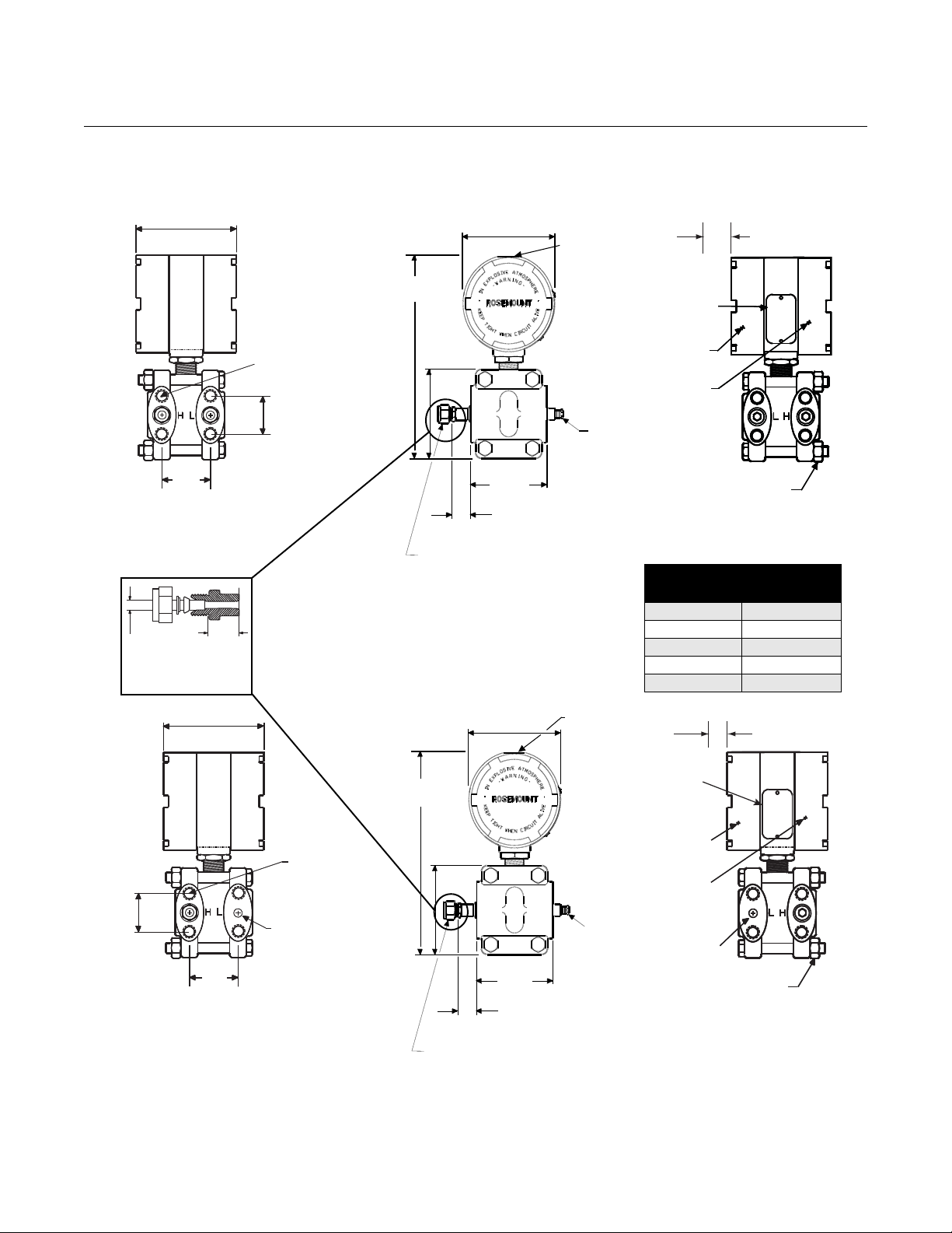
Table 6-1 on page 6-10). Figure 2-5 on page 2-7 shows transmitter
dimensional drawings.
www.rosemountnuclear.com
Page 10

Rosemount 1153 Series D
Reference Manual
00809-0100-4388, Rev BA
January 2008
1-2
Page 11
Reference Manual
Electronics
Qualified Life
Ambient Temperature (°F)
Time (Years)
Module
Qualified
Life
00809-0100-4388, Rev BA
January 2008
Rosemount 1153 Series D
Section 2 Installation
Overview . . . . . . . . . . . . . . . . . . . . . . . . . . . . . . . . . . . . . . . page 2-1
General Considerations . . . . . . . . . . . . . . . . . . . . . . . . . . . page 2-1
Mechanical Considerations . . . . . . . . . . . . . . . . . . . . . . . . page 2-2
Electrical Considerations . . . . . . . . . . . . . . . . . . . . . . . . . . page 2-4
Installation Procedures . . . . . . . . . . . . . . . . . . . . . . . . . . . page 2-6
OVERVIEW This section contains information and instructions regarding the following
installation-related information:
• General Considerations
• Mechanical Considerations
Process Connections
Conduit
• Electrical Considerations
• Installation Procedures
Mechanical
Electrical
GENERAL
CONSIDERATIONS
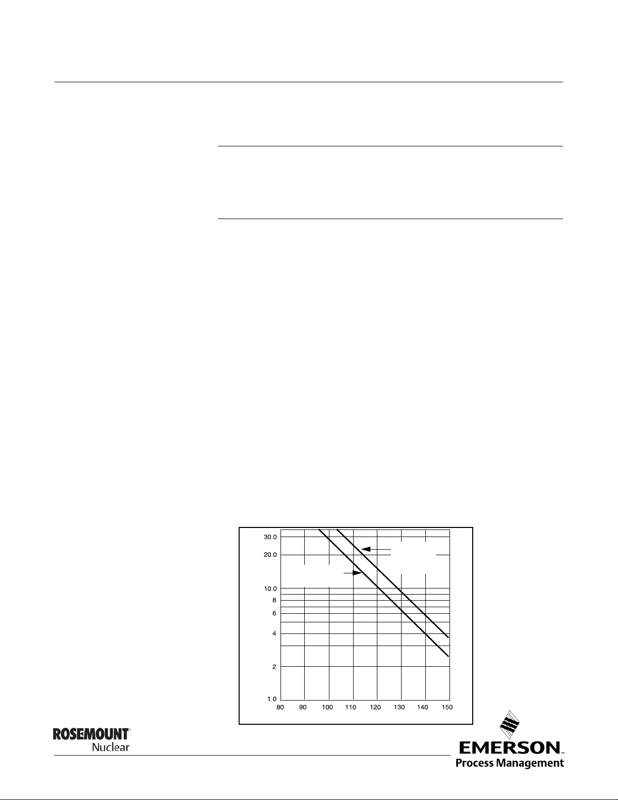
Figure 2-1. Qualified Life vs.
Ambient Temperature.
The quality and accuracy of flow, level, or pressure measurement depends
largely on the proper installation of the transmitter and its associated impulse
piping and valves. For flow measurement, proper installation of the primary
measuring element is also critical to the accuracy of the measurement.
Transmitter installation should minimize the effects of temperature gradients
and temperature fluctuations, and avoid vibration and shock during normal
operation. Take care when designing the measurement to minimize the error
caused by incorrect installation. The ambient temperature of the transmitter
environment affects the qualified life of the transmitter (see Figure 2-1 on
page 2-1).
www.rosemountnuclear.com
Page 12

Rosemount 1153 Series D
Reference Manual
00809-0100-4388, Rev BA
January 2008
MECHANICAL
CONSIDERATIONS
This section contains information you should consider when preparing to
mount the transmitter. Read this section carefully before proceeding to the
mechanical installation procedure.
Mount the Rosemount 1153 Series D transmitter to a rigid support (a support
with a fundamental mechanical resonant frequency of 40 Hz or greater). A
mounting bracket included with the transmitter facilitates panel mounting.
Figure 2-4 on page 2-6 shows qualified transmitter mounting configurations.
The transmitter was seismic tested and qualified with the bracket mounted
using four
3
/8-in. diameter bolts. Orientation with respect to gravity is not
critical to qualification. However, if the transmitter is mounted with the flanges
in a horizontal position, rezero the transmitter to cancel the liquid head effect
caused by the difference in height of the process connections.
If you mount the transmitter to a non-rigid panel, ensure that seismic input to
the mounting bracket does not exceed qualification levels given in Rosemount
Report D8300040.
Process Connections Process tubing installation must prevent any added mechanical stress on the
transmitter under seismic disturbances. This may be done by using
stress-relief loops in the process tubing or by separately supporting the
process tubing close to the transmitter.
The process connections to the transmitter flanges were qualified with
tubing using compression fittings (Swagelok
®
). For options using 1/4–18 NPT
connections, the user assumes responsibility for qualifying the interface.
Transmitters with Flange Options A, D, H, J, L, or M are shipped with
Swagelok fittings for process connections. Included are front ferrule, rear
ferrule, and nut. Ensure that they are placed on the tubing with the orientation
and relative position shown in Detail A, Figure 2-5 on page 2-7.
Process tubing used is
3
/8-in. outside diameter, and of suitable thickness for
the pressure involved.
3
/8-in.
2-2
The Swagelok tube fittings come completely assembled and are ready for
immediate use. Do not disassemble them before use; because they may
become dirty or a foreign material get into the fitting and cause leaks. Insert
the tubing into the Swagelok tube fitting, making sure that the tubing rests
firmly on the shoulder of the fitting and that the nut is finger tight. Tighten the
nut one-and-one-quarter turns and it is ready for use. Do not overtighten.
The connections can be loosened and retightened 20–30 times without
compromising the leak-proof seal. To reconnect, insert the tubing with
pre-swaged ferrules into the fitting until the front ferrule sits in the fitting.
Tighten the nut by hand, then rotate one-quarter turn more or to the original
one-and-one-quarter tight position. Then snug it slightly with a wrench. For
more information regarding the use of Swagelok tube fittings, refer to:
Fittings Catalog MS-01-140
“Gaugeable Tube Fittings and Adapter Fittings”
www.swagelok.com
If the drain/vent valves must be opened to bleed process lines, torque them to
1
7
/2 ft-lb (10 N-m) when closing.
Page 13

Reference Manual
00809-0100-4388, Rev BA
January 2008
Rosemount 1153 Series D
Proper location of the transmitter with respect to the process tubing depends
on various process parameters. When determining the best location, consider
the following:
• Keep hot or corrosive fluids from contacting the transmitter.
• Prevent sediment from depositing in the impulse tubing.
• Ambient temperature gradients and fluctuations can result in erroneous
transmitter readings.
• Keep impulse tubing as short as possible.
• For differential transmitters, balance the liquid head on both legs of the
impulse tubing.
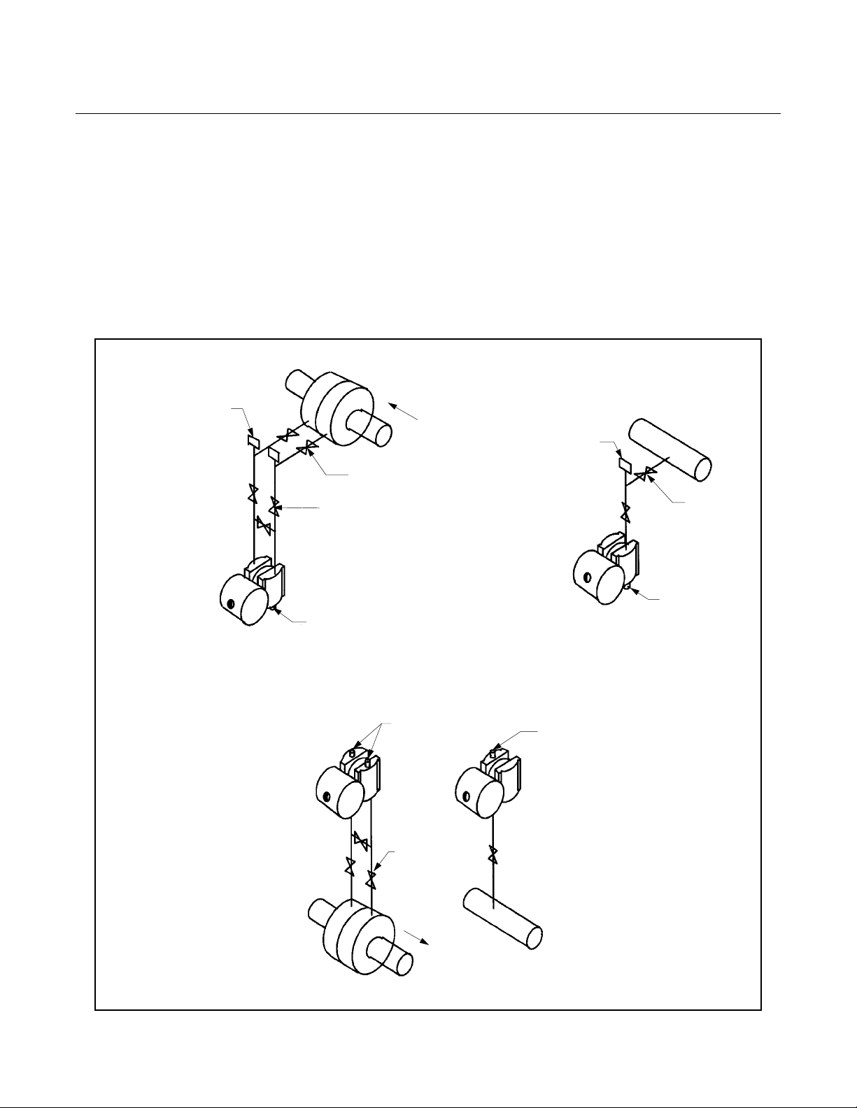
• For liquid flow or pressure measurements, make taps on the side of the
line to avoid sediment deposits, and mount the transmitter beside or
below the taps so gases vent into the process line (see Figure 2-6 on
page 2-8).
• For gas flow or pressure measurements, make taps on the top or side
of the line and mount the transmitter beside or above the taps so liquid
drains into the process line (see Figure 2-6 on page 2-8).
• For steam flow or pressure measurements, make taps on the side of
the line, and mount the transmitter below the taps so the impulse tubing
stays filled with condensate (See Figure 2-6 on page 2-8).
• For steam service, fill the lines with water to prevent steam from
contacting the transmitter. Condensate chambers are not necessary
since the volumetric displacement of the transmitter is negligible.
The piping between the process and the transmitter must transfer the
pressure measured at the process taps to the transmitter. Possible sources of
error in this pressure transfer are:
•Leaks.
• Friction loss (particularly if purging is used).
• Trapped gas in a liquid line or trapped liquid in a gas line (head error).
• Temperature-induced density variation between legs (head error), for
differential transmitters.
To minimize the possibility of errors, take the following precautions:
• Make impulse tubing as short as possible.
• Slope tubing at least one inch per foot up toward the process
connections for liquid and steam.
• Slope tubing at least one inch per foot down toward the process
connections for gas.
• Avoid high points in liquid lines and low points in gas lines.
• Use impulse tubing of sufficient diameter to avoid friction effects.
• Ensure that all gas is vented from liquid tubing legs.
• Ensure that impulse tubing is of adequate strength to be compatible
with anticipated pressures.
2-3
Page 14

Rosemount 1153 Series D
For differential transmitters, also consider the following:
• Keep both impulse legs at the same temperature.
• When using sealing fluid, fill both piping legs to the same level.
• When purging, make the purge connection close to the process taps
and purge through equal lengths of the same size tubing. Avoid purging
through the transmitter.
Reference Manual
00809-0100-4388, Rev BA
January 2008
Conduit The conduit connection to the transmitter is
conduit seal at the conduit entry to prevent moisture from accumulating in the
terminal side of the housing during accident conditions. To prevent the conduit
from adding mechanical stress to the transmitter during seismic disturbances,
use flexible conduit or support the conduit near the transmitter. Install the
conduit seal in accordance with the manufacturer’s instructions or use the
procedure on page 2-8.
ELECTRICAL
CONSIDERATIONS
This section contains information that you should consider when preparing to
make electrical connections to the transmitter. Read this section carefully
before proceeding to the electrical installation procedures.
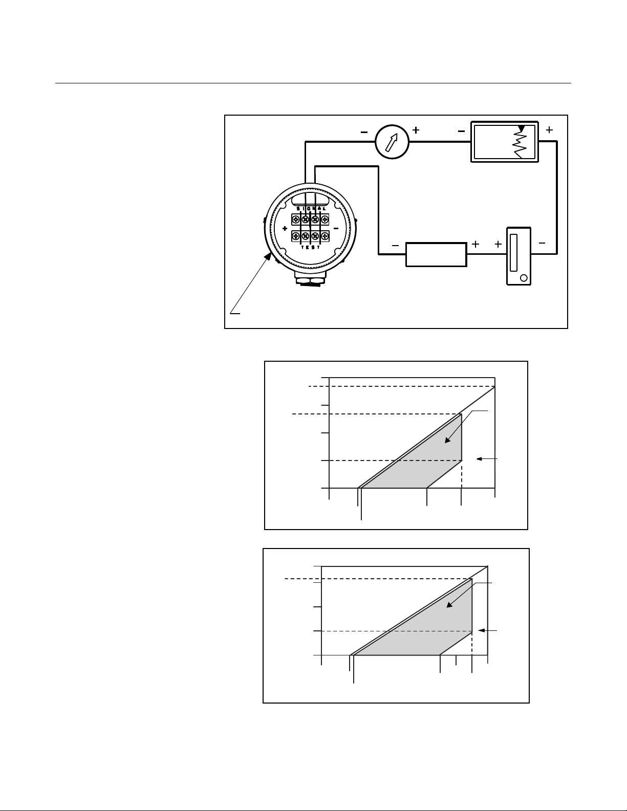
The Rosemount 1153 Series D pressure transmitter provides a 4–20 mA
signal when connected to a suitable dc power source. Figure 2-2 on page 2-5
illustrates a typical signal loop consisting of transmitter, power supply, and
various receivers (i.e., controller, indicator, computer). The power supply must
supply at least 12 volts to the transmitter terminals at 30 mA (overscale)
signal, or the maximum output current required for proper system operation.
Any power supply ripple appears in the output load. The supply voltage
versus load limitation relationship is shown in Figure 2-3 on page 2-5. See
qualification report D8300040 for details. The load is the sum of the resistance
of the signal leads and the load resistance of the receivers.
Signal wiring need not be shielded, but twisted pairs yield the best results. In
electrically noisy environments, shielded cable should be used for best
results. Do not run signal wiring in conduit or open trays with power wiring, or
near heavy electrical equipment. Signal wiring may be ungrounded (floating)
or grounded at any place in the signal loop. The transmitter case may be
grounded or ungrounded.
1
/2–14 NPT. Use a qualified
2-4
The capacitance-sensing element uses alternating current to generate a
capacitance signal. This alternating current is developed in an oscillator circuit
with a frequency of 32,000 ±10,000 Hz. This 32,000 Hz signal is capacitor
coupled to transmitter case ground through the sensing element. Because of
this coupling, a voltage may be imposed across the load, depending on
choice of grounding.
This impressed voltage, which is seen as high-frequency noise, has no effect
on most instruments. Computers with short sampling times in a circuit where
the negative transmitter terminal is grounded will detect a significant noise
signal. Filter this noise with a large capacitor (1 µf) or by using a 32,000 Hz LC
filter across the load. Signal loops grounded at any other point are negligibly
affected by this noise and do not need filtering.
Page 15
Reference Manual
Power
Supply
Terminal Side
(Cover Removed)
4—20 mA DC
Design
Region
Qualified
Region
2000
1650
1325
1500
1000
500
0
0
12
13.5
30
40
45
Power Supply (V DC)
Load Resistance (Ω)
4—20 mA DC
Design
Region
Qualified
Region
1825
1575
1500
1000
500
0
0
12
13.5
35
40
45
50
Power Supply (V DC)
Load Resistance (Ω)
00809-0100-4388, Rev BA
January 2008
Figure 2-2. Transmitter Wiring Connections.
Rosemount 1153 Series D
Figure 2-3. Transmitter Load
Limits.
Output Code P
Output Code R
2-5
Page 16
Rosemount 1153 Series D
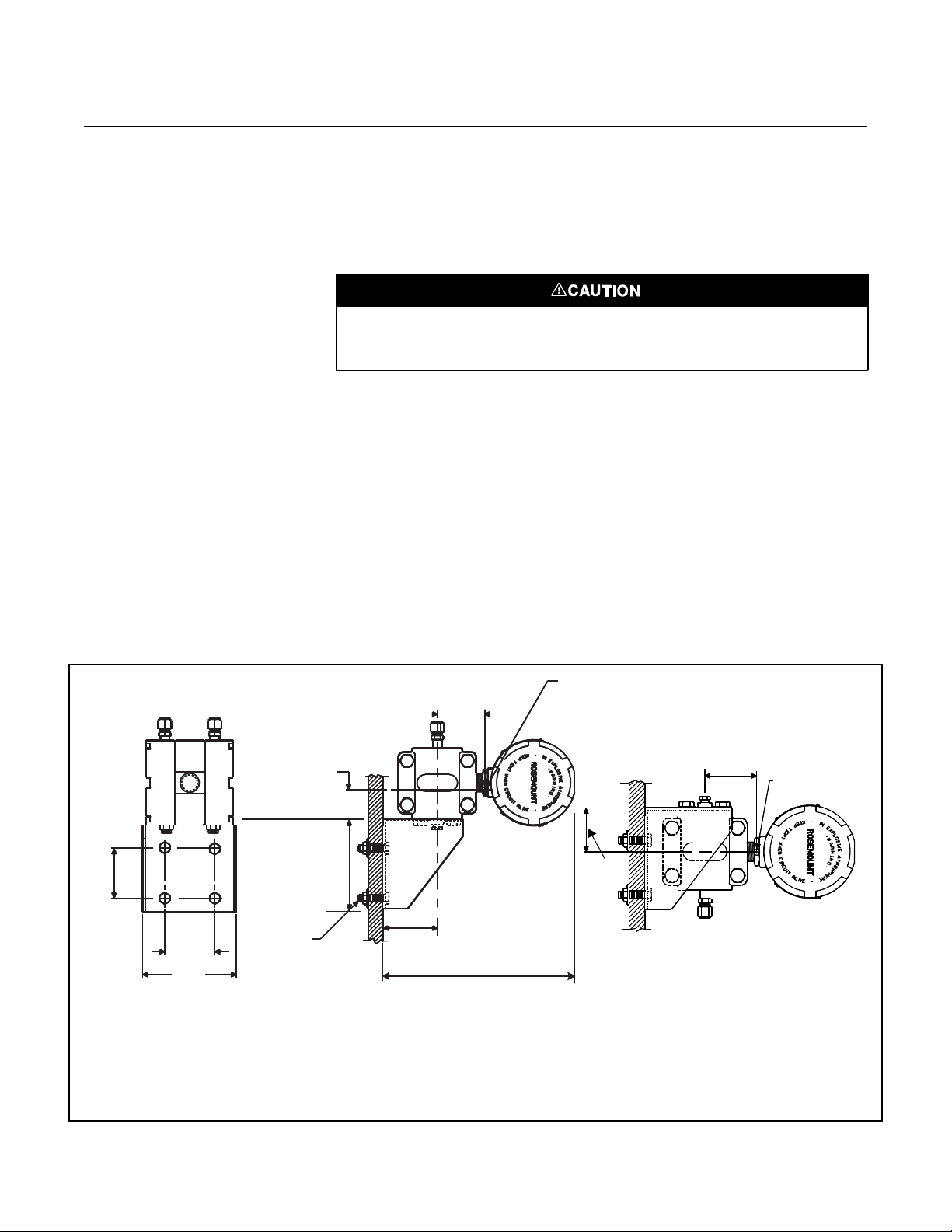
PANEL MOUNTING
HOLE PATTERN
(BACK SIDE)
Center of Gravity
(Bracket Included)
2.81
(71.4)
5
(127)
1.2
(30)
2.3
(58)
2.75
(69.9)
10 (254) Minimum
Clearance
3
/8-in.
Bolts (4)
(Customer
Supplied)
ACCEPTABLE ALTERNATE MOUNTING
2.3
(58)
NOTE
All dimensions are nominal in inches (millimeters).
Center of Gravity
(Bracket Included)
1.8
(45.7)
MOUNTING BRACKET
FOR PANEL MOUNT
SHOWN IN TYPICAL
MOUNTING CONFIGURATION
NOTES
1. Orientation with respect to gravity is not critical.
2. Units can alternately be mounted with process
connection adjacent to bracket.
4.93
(125)
2.81
(71.4)
Reference Manual
00809-0100-4388, Rev BA
January 2008
INSTALLATION
PROCEDURES
Mechanical
Transmitter
Installation consists of mounting the transmitter and conduit and making
electrical connections. Following are procedures for each operation.
Be careful not to break the neck seal between the sensor module and the
electronics housing.
The threaded interface between the sensor module and the electronics
housing is hermetically sealed before shipment. The integrity of this seal is
necessary for the safe operation of the transmitter during accident conditions.
If the seal is broken, reseal it according to “Connecting Electrical Housing to
Sensor Module” on page 5-5.
1. Mount the bracket to a panel or other flat surface (see Figure 2-4 on
page 2-6). Use four
3
/8-in. diameter bolts (not supplied with unit). SAE
grade 2 bolts were used during qualification testing. Torque each bolt
to 19 ft-lb (26 N-m).
2. Attach the transmitter to the mounting bracket (see Figure 2-4 on
page 2-6). Use four
7
/16–20 ⫻ 3/4 bolts with washers (supplied with
unit). Torque each bolt to 21 ft-lb (29 N-m).
Figure 2-4. Typical Transmitter Mounting Bracket Configuration.
2-6
Page 17
Reference Manual
Low Side
Vent
(GD only)
7
/16–20
UNF
(Typical)
9 Max.
(228.6)
4.7 Max. (119.4)
4.72 Max.
(119.9)
3.4
(86.4)
7
/16–14 UNC
(4 Places)
Nameplate
(Remove for
Zero and Span
Adjust)
Transmitter
Circuitry
(this Side)
Terminal
Connections
(this Side)
Dim
A
0.8 (20) to End
of Mating Tubing
Compression Fittings (1)
Swagelok for
3
/8-in. Tubing
(Optional
1
/4–18 NPT Available)
Welded
Drain/Vent
Valve (1)
(Optional
1
/4–18 NPT
Available)
Low Side
Vent
(GD only)
DETAIL A
3
/8-in.
Mating
Tubing
0.8
(20)
Welded
Drain/Vent Valve
(2) (Optional
1
/4–18 NPT
Dim.
A
1.63
(41.3)
7
/16–20
UNF
(Typical)
9 Max.
(228.6)
3.7
(94)
4.7 Max. (119.4)
4.72 Max. (119.9)
3.4
(86.4)
7
/16–14 UNC
(4 Places)
Nameplate
(Remove for
Zero and Span
Adjust)
Transmitter
Circuitry
(this Side)
Terminal
Connections
(this Side)
0.8 (20) to End
of Mating Tubing
Compression Fittings (2)
Swagelok
®
for 3/8-in. Tubing
(Optional
1
/4–18 NPT Available)
Pressure
Range Code
Dimension
A
3, 4, 5 2.13 (54)
6, 7 2.19 (55.6)
8 2.25 (57.2)
9 2.28 (57.9)
0 2.33 (59.1)
ROSEMOUNT 1153DD AND 1153HD
ROSEMOUNT 1153AD AND 1153GD
3.7
(94)
1
/2–14 NPT
Conduit
Connection
(1 place)
1
/2–14 NPT
Conduit
Connection
(1 place)
0.75 (19) Clearance
for Cover Removal
(Typical)
0.75 (19) Clearance
for Cover Remov al
(Typical)
1.63
(41.3)
NOTE
All dimensions are nominal in inches (millimeters).
00809-0100-4388, Rev BA
January 2008
Figure 2-5. Transmitter Dimensional Drawings.
Rosemount 1153 Series D
2-7
Page 18
Reference Manual
Blocking Valves
Flow
3-Valve Manifold
Plugged Tees for Steam
Service or Sealing Fluid
Drain/Vent
Valves
Sufficient
Length
for Cooling
Rosemount 1153DD, HD
Plugged Tees for
Steam Service or
Sealing Fluid
Blocking
Valve
Drain/Vent
Valve
Sufficient
Length
for Cooling
Rosemount 1153AD, GD
Rosemount 1153AD, GD
LIQUID SERVICE
Drain/Vent
Valve s
Drain/Vent
Valve
3-Valve
Manifold
Flow
Rosemount 1153DD, HD
GAS SERVICE
H
H
L
L
00809-0100-4388, Rev BA
Rosemount 1153 Series D
January 2008
Conduit 1. Seal the conduit threads with thread sealant (the transmitter conduit
seal interface was qualified using Grafoil™ tape). Conduit threads
mate with a standard
2. Starting at zero thread engagement, install the conduit into the
transmitter between 4 and 7 turns, or a minimum of 12.5 ft-lb (16.9
N-m). Hold the electronics housing securely to avoid damaging the
threaded neck seal between the sensor module and the electronics
housing during conduit installation.
3. Provide separate support for the conduit if necessary.
Figure 2-6. Transmitter Installation Configurations
1
/2–14 NPT male fitting.
2-8
Page 19
Reference Manual
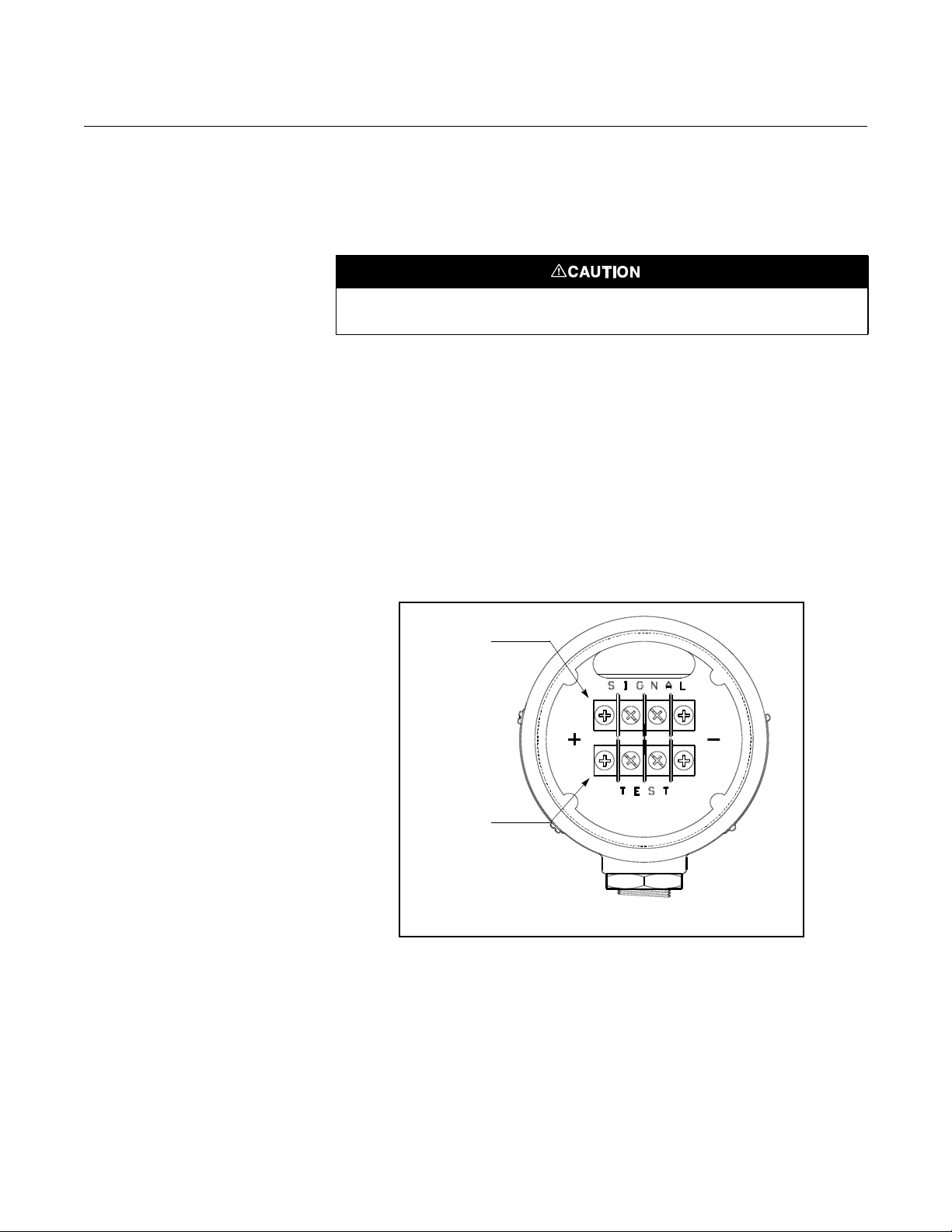
Signal
Terminals
Test Terminals
00809-0100-4388, Rev BA
January 2008
Rosemount 1153 Series D
Electrical 1. Remove the cover from the terminal side of the transmitter (see
Figure 2-5 on page 2-7).
2. Connect the power leads to the “SIGNAL” terminals on the transmitter
terminal block (see Figure 2-7 on page 2-9). Torque the terminal
screws to 5 in-lb (0.6 N-m), or hand-tight.
Do not connect signal leads to the “TEST” terminals.
3. Recheck the connections for proper polarity.
4. Check the cover O-ring grooves for cleanliness. If chips or dirt are
present, clean the seat and mating portion of the cover with alcohol.
Lubricate replacement O-ring with O-ring grease (RMT P/N
01153-0248-0001 or P/N 01153-0053-0001). The transmitter was
qualified using Dow Corning
5. Spray the inside threads of the electronics covers with cover lubricant
(Rosemount P/N 01153-0333-0001 or equivalent) if necessary; if
covers are already sufficiently lubricated, do not spray.
6. Carefully replace the cover and tighten to 16.5 ft-lb (22.4 N-m).
®
55 Silicone O-ring Grease.
Figure 2-7. Transmitter Terminal Block.
2-9
Page 20

Rosemount 1153 Series D
Reference Manual
00809-0100-4388, Rev BA
January 2008
2-10
Page 21

Reference Manual
00809-0100-4388, Rev BA
January 2008
Rosemount 1153 Series D
Section 3 Calibration
Overview . . . . . . . . . . . . . . . . . . . . . . . . . . . . . . . . . . . . . . . page 3-1
Calibration . . . . . . . . . . . . . . . . . . . . . . . . . . . . . . . . . . . . . . page 3-1
Calibration Procedures . . . . . . . . . . . . . . . . . . . . . . . . . . . page 3-3
OVERVIEW Each transmitter is factory calibrated to the range specified by the customer.
This section contains the following transmitter calibration information:
• Calibration
Span Adjustment
Zero Adjustment
• Calibration Procedures
Span and Zero Adjustment
Linearity Adjustment
Damping Adjustment
Correction for High Line Pressure
CALIBRATION The Rosemount 1153DD, HD, GD, and AD Transmitters are factory calibrated
to the range shown on the nameplate. This range may be changed within the
limits of the transmitter. Zero may also be adjusted to elevate (for all models
except the Rosemount 1153AD) or suppress (for all models). The span and
zero adjustments are external and located under the nameplate.
Span Adjustment The span on any Rosemount 1153 Series D Pressure Transmitter is
continuously adjustable to allow calibration anywhere between maximum
span and
example, the span on a Range Code 4 transmitter can be continuously
adjusted between 0–150 and 0–25 inH
1
/6 of maximum span (¼ of maximum span for Range 0). For
O.
2
Zero Adjustment The zero can be adjusted for up to 500 percent of span suppression
(300 percent for Range code 0) or 600 percent of span elevation
(400 percent for Range code 0) (see Figure 3-1 on page 3-2).
The zero may be elevated or suppressed to these extremes with the limitation
that no applied pressure within the calibrated range exceeds the full-range
pressure limit. For example, a Range Code 4 transmitter cannot be calibrated
for 150 to 200 in H
H
O exceeds the 150 inH2O upper range pressure limit of a Range Code 4.
2
The transmitter may be calibrated to cross zero (e.g., –75 to 75 inH
this may result in a slight loss of linearity
O (only 300 percent zero suppression) because the 200 in
2
O) but
2
www.rosemountnuclear.com
Page 22

Rosemount 1153 Series D
600% Zero Elevation
Output
(mA)
20
4
Pressure (inH2O)
600% Zero Elevation
➀
20
Output
(mA)
4
0
25
Pressure (inH2O)
No Zero Elevation or Suppression
➀
20
4
Output
(mA)
➀Graphs based on a Range 4 (0-25 to 0-150 inH2O)
Rosemount 1153 Series D with a calibrated span of 25 inH
2
O.
-150 -125 -100
-75 -50
-25 0
25
0
25 50
75 100 125 150
Pressure (inH2O)
500% Zero Suppression
➀
Figure 3-1. Zero Adjustment
Range.
Reference Manual
00809-0100-4388, Rev BA
January 2008
3-2
Page 23

Reference Manual
Zero
Span
00809-0100-4388, Rev BA
January 2008
CALIBRATION
PROCEDURES
Rosemount 1153 Series D
Zero and Span
Adjustment
Figure 3-2. Zero and Span
Adjustment.
NOTE
The Rosemount 1153 Series D Pressure Transmitter contains electronic
circuit boards which may be static sensitive.
NOTE
Covers need not be removed for zero and span adjustment.
The zero and span adjustment screws are accessible externally. They are
located behind the nameplate on the side of the electronics housing (see
Figure 3-2 on page 3-3). The transmitter output increases with clockwise
rotation of the adjustment screws.
The zero adjustment screw has very little effect on the span. The span
adjustment, however, does affect the zero. The effect of interaction is more
apparent with suppression or elevation. The span adjustment changes the
zero output and the full-scale output by approximately the same percentage.
Therefore, it is best to calibrate the transmitter from zero to the desired span
and finish the calibration by adjusting the zero screw to achieve the desired
elevation or suppression.
Example (for Range Code 4)
Initial Transmitter Calibration: 25 to 125 inH
(100 inH
Desired Transmitter Calibration: –75 to –25 inH
(50 inH
O span with zero suppressed 25 inH2O).
2
O span with zero elevated 75 inH2O).
2
O
2
O
2
3-3
Page 24

Rosemount 1153 Series D
4 mA
Existing Span
Desired Span
------------------------------------
× 4 mA
100 inH2O
50 inH2O
------------------------------ -
× 8 mA==
19.900 + (20.000 – 19.900) ⫻ 1.25 = 19.900 + 0.125 = 20.025
1. Adjust the zero to eliminate any existing zero elevation or
suppression. With 0 inH
the zero adjustment until the output reads 4 mA. The unit is now
calibrated for 0 to 100 inH
2. Adjust the span to the desired new span. To reduce the span, turn the
span screw until the output, with 0 inH
8 mA:
Reference Manual
00809-0100-4388, Rev BA
January 2008
O pressure applied to the transmitter, turn
2
O.
2
O pressure input, equals
2
3. Adjust the zero screw to bring the output, with 0 inH
O input, back to
2
4 mA. The transmitter calibration should now be very close to 0 to 50
inH
O.
2
4. Check the full-scale output and fine tune the span and zero
adjustment if required. Remember zero adjustments do not affect
span, but span adjustments do affect zero predictably. Adjusting the
span screw affects the zero
1
/5 as much as it affects the span. To
compensate for this effect, simply overadjust by 25 percent. For
example, if, after completing step 3, the transmitter output reads
19.900 mA at 50 inH
(at 50 inH
O) reads 20.025 mA.
2
Since the span adjustment affects zero
O, turn the span potentiometer until the output
2
1
/5 as much as the span, the
0.125 mA increase in span causes a 0.025 mA increase in zero.
Therefore, turn the zero adjustment (at 50 inH
O) until the output
2
reads 20.000 mA. The unit should now be calibrated for 0 to 50 in
H
O.
2
5. Zero Elevation/Suppression. Elevate zero. Turn the screw until the
output reads 4 mA with –75 inH
transmitter (applying 75 inH
O applied to the high side of the
2
O to the low side will give the same
2
result). The output may stop changing before the desired 4 mA
reading is obtained. If this occurs, turn off power to the unit and
unplug the amplifier board (refer to Electrical Housing Disassembly
procedure on page 5-4 for cover removal and Figure 5-2 on page 5-7
to locate the amplifier board). To elevate or suppress zero a large
amount, use the following procedure:
A. Material
• Wire: 22 gauge tinned solid copper-Fed Spec QQW343, ASTM B33.
• Solder: 60% tin, 40% lead (60/40)-Fed Spec QQ-S-571.
• Flux: Mil F 14256, Type A, Fed Spec QQ-S-571 Type RA.
For transmitters with Output Code P electronics, follow Method B1 for Zero
Elevation/Suppression if the amplifier board has four holes. Follow Method B2
if the amplifier board has three turrets (see Figure 3-3 on page 3-7).
For transmitters with Output Code R electronics, follow Method B2.
3-4
Page 25

Reference Manual
00809-0100-4388, Rev BA
January 2008
Rosemount 1153 Series D
B1. Method (Output Code P—Amplifier Board with Holes)
a. Cut the jumper wire, form, and insert across 2 jumper pads on the
component side of the board in the “elevate zero” position (see
Figure 3-3 (Detail A2) on Page 3-7).
b. Turn the board over and clip the wire ends to the appropriate
length. In accordance with proper electronic practices, solder the
jumper wire to the board. Clean solder joints with isopropyl alcohol.
c. Plug the amplifier board back in and complete the zero adjustment.
To suppress zero follow the same procedure except position the jumper wire
on the board in the “suppress zero” position (see Figure 3-3 (Detail A3) on
Page 3-7).
B2. Method (Output Code R and Output Code P—Amplifier Board with
Turrets)
a. Locate 3 turret terminals on the component side of the amplifier
board. Remove any jumper wires between them (Figure 3-3 on
page 3-7).
b. To elevate zero, connect a jumper wire between the middle
terminal and the terminal marked “EZ” (see Figure 3-3 (Detail B2)
on Page 3-7).
c. Wrap the jumper wire once around each terminal and cut off the
excess.
d. Solder the jumper wire to the terminals using proper electronics
soldering techniques. Clean solder joints thoroughly with isopropyl
alcohol.
e. Plug the amplifier board back in and complete the zero adjustment.
To suppress zero, follow the same procedure, except connect the jumper wire
between the middle terminal and the terminal marked “SZ” (see Figure 3-3
(Detail B3) on Page 3-7).
6. Recheck full scale and zero and fine tune if necessary.
NOTE
There is some mechanical backlash in the zero and span adjustments, so
there will be a dead band when you change the direction of adjustment.
Because of the backlash, the simplest procedure, if the desired setting is
overshot, is to intentionally overshoot a larger amount before reversing the
direction of the adjustment.
Linearity Adjustment In addition to the span and zero adjustments, there is a linearity adjustment
located inside the transmitter on the amplifier board (see Figure 3-4 on
page 3-8). Linearity is factory calibrated for optimum performance over the
calibrated range of the instrument and is not normally adjusted in the field. If
you want to maximize linearity over some particular range, use the following
procedure:
3-5
Page 26

Rosemount 1153 Series D
Rangedown Factor
Maximum Allowable Span
Calibrated Span
-------------------------------------------------------------------- -=
1. Apply mid-range pressure and note the error between theoretical and
actual output signal.
2. Apply full-scale pressure. Multiply the error noted in step 1 by six and
by the rangedown factor.
3. Add the result to the full-scale output for negative errors, or subtract
the result from the full-scale output for positive errors, by adjusting the
linearity trimmer (see Figure 3-4 on page 3-8). Example: At 4-to-1
rangedown the midscale point is low by 0.05 mA. Therefore, adjust
the “Linearity” trimmer until full-scale output increases by (0.05 mA ⫻
6 ⫻ 4) = 1.2 mA.
4. Readjust zero and span.
NOTE
If you remove either cover during the above procedures, replace the
O-ring and torque the cover per the instructions given in Section 5
Maintenance and Troubleshooting. Spare cover O-rings are supplied with
each transmitter.
Reference Manual
00809-0100-4388, Rev BA
January 2008
3-6
Page 27

Reference Manual
“P” OUTPUT
Moderate Elevation/
Suppression
(No Jumper Wire)
Jumper Wire
Jumper Wire
DETAIL A1
DETAIL A2
(To Elevate Zero)
DETAIL A3
(To Suppress Zero)
EZ
SZ
EZ
SZ
EZ
SZ
Moderate Elevation
Suppression
(No Jumper Wire)
Jumper Wire
Jumper Wire
DETAIL B1
DETAIL B2
(To Elevate Zero)
DETAIL B3
(To Suppress Zero)
“R” OUTPUT AND “P” OUTPUT WITH TURRETS
00809-0100-4388, Rev BA
January 2008
Figure 3-3. Jumper Wire Placement.
Rosemount 1153 Series D
3-7
Page 28

Reference Manual
Damping Adjustment
(Optional on “R”
Electronics Only)
Linearity
Adjustment
Electronics Side of
Transmitter Housing
(Cover Removed)
00809-0100-4388, Rev BA
Rosemount 1153 Series D
January 2008
Figure 3-4. Linearity and
Damping Adjustment.
Damping Adjustment Damping electronics are available as an option. Transmitters with standard
electronics can be retrofitted with the adjustable damping feature by changing
out both the amplifier board (RMT P/N 01154-0021-0004) and the calibration
board (RMT P/N 01154-0023-0002).
The damping adjustment permits damping of rapid pressure variations by
adjusting the single-turn trim potentiometer located on the upper right-hand
side of the amplifier board (see Figure 3-4 on page 3-8). The available
settings, when adjusted to the maximum position, provide time-constant
values of at least 1.2 seconds for Range Code 4 and 0.8 seconds for Range
Codes 5–9. Transmitters with the electronic damping option are calibrated
and shipped with the adjustment set at the counterclockwise stop, giving the
minimum time-constant.
To adjust the damping, turn the damping adjustment potentiometer until the
desired time-constant is obtained. It is best to set the damping to the shortest
possible time-constant. Since transmitter calibration is not affected by the
damping setting, you may adjust the damping with the transmitter installed in
the process.
The damping adjustment potentiometer has positive stops at both ends.
Forcing the potentiometer beyond the stops may cause permanent
damage.
NOTE
If you remove either cover during the above procedures, replace the
O-ring and torque the cover per the instructions provided in Section 5
Maintenance and Troubleshooting. Spare cover O-rings are supplied with
each transmitter.
3-8
Page 29

Reference Manual
0.75 %
1,000 psi
----------------------- - 1200 psi 0.9% differential input=×
0.9 % 100 inH
2
–× O 0.9 inH2O–=
0.9 i n H2O–
400 i n H2O input span
----------------------------------------------------------- 0.225 % span–=
0.225 % 16 mA span×– 0.036 mA–=
4.00 mA 0.036 3.964 mA=–
00809-0100-4388, Rev BA
January 2008
Correction For High Line
Pressure (Rosemount
1153DD and 1153HD
Only)
Rosemount 1153 Series D
Span
If a differential transmitter is calibrated with the low side at ambient pressure
but will be used at high line pressure, correct the span adjustment to
compensate for the effect of static pressure on the unit. If zero is elevated or
suppressed, also correct the zero adjustment. Correction factors, expressed
in percent of differential pressure input at end points per 1,000 psi static
pressure, are:
Range 3:
+1.5% of input/1,000 psi
Ranges 4, 5, and 8:
+0.75% of input/1,000 psi
Ranges 6 and 7:
+1.25% of input/1,000 psi
The correction procedure below uses the following example: Range 5,
calibrated –100 to 300 inH
that steps 3–6 are omitted for ranges based at zero differential pressure.
1. Calibrate the unit per preceding section to output = 4 mA at
–100 inH
2. Calculate correction factor:
O and 20 mA at 300 inH2O.
2
O to be operated at 1,200 psi line pressure. Note
2
3. Calculate zero adjustment correction in terms of pressure:
4. Convert pressure correction to percent of input span:
5. Calculate correction in terms of output span (mA):
6. Add the milliamp correction to the ideal zero output (4 mA). This is the
corrected ideal zero output:
3-9
Page 30

Rosemount 1153 Series D
0.9 % 300 i nH
2
× O 2.7 inH2O=
2.7 i n H2O
400 i n H
2
O input span
----------------------------------------------------------- 0.675 % span=
0.675 % 16 mA span× 0.108 mA=
20.00 mA 0.108 mA 20.108 mA=+
7. Calculate full-scale adjustment correction in terms of pressure:
8. Repeat step 4 with the results of step 7:
9. Repeat step 5 with the result of step 8:
10. Add the mA correction to the ideal full-scale output (20 mA). This is
the corrected ideal full-scale output.
11. Readjust zero and span adjustments for corrected outputs:
Reference Manual
00809-0100-4388, Rev BA
January 2008
3.964 mA at –100 inH2O
20.108 mA at 300 inH2O
There is an uncertainty of ±0.5 percent of input reading per 1,000 psi
associated with the span correction.
Zero Zero shift with static pressure is not systematic. However, if the calibrated
range includes zero differential pressure, the effect can be trimmed out after
installation and with the unit at operating pressure.
Equalize pressure to both process connections, and turn the zero adjustment
until the ideal output at zero differential input is observed. Do not readjust the
span potentiometer.
If the transmitter does not include zero differential pressure within its
calibrated span, the zero effect or zero correction can be determined before
the unit is suppressed or elevated to eliminate the zero effect after correcting
for the span effect.
The following procedure illustrates how to eliminate the zero effect for a
non-zero differential pressure calibration. The example uses a Range 5
calibrated from 100 to 500 inH
O with 1,200 psi static line pressure.
2
3-10
Page 31

Reference Manual
00809-0100-4388, Rev BA
January 2008
Rosemount 1153 Series D
1. Using standard calibration procedures, calibrate the unit to the
required span, with the 4 mA or zero point corresponding to zero
differential pressure:
4 mA at 0 inH2O and 20 mA at 400 inH2O
2. Apply static pressure to both high and low process connections with
zero differential pressure across the transmitter, and note the zero
correction (zero shift). For example, if the output reads 4.006 mA, the
zero correction is calculated as:
4.00 mA – 4.006 mA = –0.006 mA
Note the sign associated with this correction, as this result is added
when determining the final, ideal transmitter output.
3. Remove static pressure and correct for the span effect as outlined in
the span correction procedure. Calibrate the unit to the calculated
output values. If, for example, the span correction procedure yielded
4.029 mA and 20.144 mA, calibrate the unit for:
4.029 mA at 100 inH2O
20.144 mA at 500 inH2O
4. Add the zero correction (–0.006 mA), found in step 2, to the ideal zero
point value calculated in step 3.
4.029 mA + (–0.006 mA) = 4.023 mA
5. To eliminate the zero effect, readjust the zero potentiometer so the
output reads the ideal zero point calculated in step 4 (do not readjust
the span potentiometer). Note that all the calibration points will shift
the same amount toward the correct reading. The example output is
now 4.023 mA at 100 inH
The transmitter output is now 4–20 mA over its calibrated span when
the unit is operated at 1,200 psi static line pressure.
O.
2
3-11
Page 32

Rosemount 1153 Series D
Reference Manual
00809-0100-4388, Rev BA
January 2008
3-12
Page 33

Reference Manual
PK
1
C2C1–
C1C2+
--------------------- -
⎝⎠
⎜⎟
⎛⎞
=
00809-0100-4388, Rev BA
January 2008
Rosemount 1153 Series D
Section 4 Operation
Overview . . . . . . . . . . . . . . . . . . . . . . . . . . . . . . . . . . . . . . . page 4-1
Transmitter Operation . . . . . . . . . . . . . . . . . . . . . . . . . . . . page 4-1
The ␦-Cell Sensor . . . . . . . . . . . . . . . . . . . . . . . . . . . . . . . . page 4-3
Demodulator . . . . . . . . . . . . . . . . . . . . . . . . . . . . . . . . . . . . page 4-3
Linearity Adjustment . . . . . . . . . . . . . . . . . . . . . . . . . . . . . page 4-3
Oscillator . . . . . . . . . . . . . . . . . . . . . . . . . . . . . . . . . . . . . . . page 4-4
Voltage Regulator . . . . . . . . . . . . . . . . . . . . . . . . . . . . . . . . page 4-4
Zero And Span Adjustments . . . . . . . . . . . . . . . . . . . . . . . page 4-4
Current Control . . . . . . . . . . . . . . . . . . . . . . . . . . . . . . . . . . page 4-4
Current Limit . . . . . . . . . . . . . . . . . . . . . . . . . . . . . . . . . . . . page 4-4
Reverse Polarity Protection . . . . . . . . . . . . . . . . . . . . . . . . page 4-4
OVERVIEW This section provides brief descriptions of basic transmitter operations in the
following order:
• Transmitter Operation
™
• The ␦-Cell
• Demodulator
• Linearity Adjustment
• Oscillator
• Voltage Regulator
• Zero and Span Adjustments
• Current Control
• Current Limit
• Reverse Polarity Protection
Sensor
TRANSMITTER
OPERATION
www.rosemountnuclear.com
The block diagram in Figure 4-1 on page 4-2 illustrates the operation of the
transmitter.
Rosemount 1153 Series D Alphaline Pressure Transmitters have a variable
capacitance sensing element, the
Differential capacitance between the sensing diaphragm and the capacitor
plates is converted electronically to a 2-wire 4–20 mA dc signal.
Where:
P is the process pressure.
␦-Cell (see Figure 4-2 on page 4-3).
Page 34

Rosemount 1153 Series D
fV
pp
–
I
ref
C1C2+
--------------------- -=
I
diff
fV
pp
–
C2C1–()=
PConstantI
diff
× I
ref
C2C1–
C2C1+
--------------------- -
⎝⎠
⎜⎟
⎛⎞
==
Sensor
Demodulator
Current
Detector
Oscillator
Osc.
Control
Amp.
Voltage
Regulator
Curr.
Control
Amp.
Current
Control
Current
Limiter
Reverse
Polarity
Protection
Signal
Test
–
–
–
+
+
K1is a constant.
is the capacitance between the high pressure side and the sensing
C
1
diaphragm.
is the capacitance between the low pressure side and the sensing
C
2
diaphragm.
Where:
is the current source.
I
ref
is the peak-to-peak oscillation voltage.
V
p-p
f is the oscillation frequency.
Where:
is the difference in current between C1 and C2.
I
diff
Therefore:
Reference Manual
00809-0100-4388, Rev BA
January 2008
Figure 4-1. Electrical Block
Diagram.
4-2
Page 35

Reference Manual
Lead Wires
Capacitor
Plates
Sensing
Diaphragm
Rigid
Insulation
Silicone Oil
Isolating
Diaphragm
Welded Seals
ROSEMOUNT 1153DD, HD, GD
Lead Wires
Capacitor
Plates
Sensing
Diaphragm
Rigid
Insulation
Silicone
Oil
Welded Seals
Isolating
Diaphragm
Evacuated
Absolute
Reference
ROSEMOUNT 1153AD
I
diff
= fV
p-p
(C2 – C1)
00809-0100-4388, Rev BA
January 2008
Figure 4-2. The ␦-Cell.
Rosemount 1153 Series D
THE ␦-CELL SENSOR Process pressure is transmitted through an isolating diaphragm and silicone
oil fill fluid to a sensing diaphragm in the center of the
pressure is transmitted in like manner to the other side of the sensing
diaphragm.
The position of the sensing diaphragm is detected by the capacitance plates
on both sides of the sensing diaphragm. The capacitance between the
sensing diaphragm and either capacitor plate is approximately
150 pF. The sensor is driven through transformer windings by an oscillator at
roughly 32 kHz and 30 Vp-p.
␦-Cell. The reference
DEMODULATOR The demodulator consists of a diode bridge that rectifies the ac signal from
the sensor cell to a dc signal.
(the sum of the dc currents through two
ref
LINEARITY
ADJUSTMENT
The oscillator driving current, I
transformer windings) is controlled to be a constant by an integrated circuit
amplifier.
The dc current through a third transformer winding is a current directly
proportional to pressure; i.e.:
The diode bridge and span temperature-compensating thermistor are located
inside the sensor module. The effect of the thermistor is controlled by
resistors located in the electronics housing.
Linearity is adjusted by a variable-resistance network, capacitor, and diodes.
The currents generated through this part of the circuit are summed into the
inputs of the oscillator control circuit. This provides a programmed correction
that raises the oscillator peak-to-peak voltage to compensate for first-order
nonlinearity of capacitance as a function of pressure.
4-3
Page 36

Reference Manual
fV
p-p
I
ref
C1C2+
--------------------- -=
00809-0100-4388, Rev BA
Rosemount 1153 Series D
January 2008
OSCILLATOR The oscillator has a frequency determined by the capacitance of the sensing
element and the inductance of the transformer windings.
The sensing element capacitance is variable. Therefore, the frequency is
variable about a nominal value of 32 kHz.
An integrated circuit amplifier is used as a feedback control circuit and
controls the oscillator drive voltage such that:
VOLTAGE REGULATOR The transmitter uses a zener diode, transistor, and resistors to provide a
constant voltage of 6.4 V dc for the reference and 7 V dc for the oscillator.
ZERO AND SPAN
ADJUSTMENTS
Zero adjustment components consist of a potentiometer and resistor that
develop a separate adjustable current that sums with the sensor current. The
coarse zero switch switches resistors into the circuit as needed.
Span adjustment is performed with a potentiometer that determines the
amount of loop current that is sensed and fed back to the current control
amplifier.
CURRENT CONTROL The current control amplifier consists of an integrated circuit, two transistors,
and associated components. The IC reference voltage is established at the
junction of a resistor network. The current control amplifier drives the current
control to a level such that the current detector feeds back a signal equal to
the sum of the zero current and the variable sensor current.
CURRENT LIMIT A current limiter prevents the output current from exceeding 30 mA in an
overpressure condition.
REVERSE POLARITY
A zener diode provides reverse polarity protection.
PROTECTION
4-4
Page 37

Reference Manual
00809-0100-4388, Rev BA
January 2008
Rosemount 1153 Series D
Section 5 Maintenance and
Troubleshooting
Overview . . . . . . . . . . . . . . . . . . . . . . . . . . . . . . . . . . . . . . . page 5-1
Safety Messages . . . . . . . . . . . . . . . . . . . . . . . . . . . . . . . . . page 5-1
Test Terminals . . . . . . . . . . . . . . . . . . . . . . . . . . . . . . . . . . . page 5-2
Board Checkout . . . . . . . . . . . . . . . . . . . . . . . . . . . . . . . . . page 5-2
Sensing Module Checkout . . . . . . . . . . . . . . . . . . . . . . . . . page 5-2
Disassembly Procedure . . . . . . . . . . . . . . . . . . . . . . . . . . . page 5-3
Reassembly Procedure . . . . . . . . . . . . . . . . . . . . . . . . . . . page 5-4
Post-assembly Tests . . . . . . . . . . . . . . . . . . . . . . . . . . . . . page 5-6
OVERVIEW This section outlines a technique for checking out the components, a method
for disassembly and reassembly, and a troubleshooting guide.
NOTE
Maintenance of traceability of replacement parts is the responsibility of the
user (see “Important Notice” on page 6-13 and Important Notice at beginning
of this manual, preceding Table of Contents).
The Rosemount 1153 Series D has no moving parts and requires a minimum
of scheduled maintenance. Calibration procedures for range adjustment are
outlined in Section 3, Calibration. A calibration check should be conducted
after inadvertent exposure to overpressure, unless your plant considers this
factor separately in the plant error analysis.
Test terminals are available for in-process checks. For further checks, the
transmitter can be divided into three active physical components: the sensing
module, the amplifier board, and the calibration board.
An exploded view of the transmitter is provided in Figure 5-2 on page 5-7. In
the following procedures, numbers in parentheses refer to item numbers in
the exploded view.
SAFETY MESSAGES Instructions and procedures in this section may require special precautions to
ensure the safety of the people performing the operations. Information that
raises potential safety issues is indicated by a warning message. The
following warning messages appear in this section.
Use only the procedures and new parts specifically referenced in this
manual to ensure specification performance and certification compliance.
Unauthorized procedures or parts can render the instrument dangerous
to life, limb, or property.
www.rosemountnuclear.com
Page 38

Reference Manual
Component Side Up
00809-0100-4388, Rev BA
Rosemount 1153 Series D
Process o-rings may retain some process fluid after disassembly of
process flanges. If this fluid is determined to be contaminated, take
appropriate safety measures.
January 2008
TEST TERMINAL S The test terminals are connected across a diode through which the loop
signal current passes. The indicating meter or test equipment shunts the
diode when connected to the test terminals. As long as the voltage across the
terminals is kept below the diode threshold voltage, no current passes
through the diode. To insure that there is no current leaking through the diode
while making a test reading or when connecting an indicating meter, the
resistance of the test connection or meter should not exceed 10 Ω.
BOARD CHECKOUT NOTE
Numbers in parentheses refer to item numbers in Figure 5-2 on page 5-7.
Figure 5-1. Header Board
Connections.
NOTE
The Rosemount 1153 Series D Pressure Transmitter contains electronic
circuit boards which may be static sensitive.
You can easily check the printed circuit boards (5 and 6) for a malfunction by
substituting spare boards into the circuit. If this procedure turns up a
malfunctioning board, return the defective board to Rosemount Nuclear
Instruments, Inc. for replacement. Because of parts traceability, qualification
becomes the responsibility of the customer in the event of unauthorized board
repairs.
The “R” and “P” electronics circuits boards are interchangeable and either
may be used. They must, however, be used as a pair (i.e., you must use an
“R” calibration board with the “R” amplifier board and not with the “P”
amplifier board). This also applies to the “P” calibration board.
SENSING MODULE
CHECKOUT
5-2
NOTE
Numbers in parentheses refer to item numbers in Figure 5-2 on page 5-7.
The sensing module (12) is not field-repairable and must be replaced if
defective. If no defect such as a punctured isolating diaphragm or loss of fill
fluid is observed, check the sensing module in the following manner.
Page 39

Reference Manual
00809-0100-4388, Rev BA
January 2008
Rosemount 1153 Series D
1. Disengage the header assembly board (4) as described in the
electrical housing disassembly procedure on 5-4. You need not
remove the sensing module from the electrical housing for checkout.
2. Jump connections 1 and 2 on the header assembly board (see Figure
5-1 on page 5-2).
3. Using a low-voltage ohmmeter, check the resistance between the
jumper wire and sensing module housing. This resistance should be
greater than 10 MΩ. Remove the jumper wire.
4. Jump connections 3 and 4 on the header assembly board and repeat
step 3 (see Figure 5-1 on page 5-2).
NOTE
The above procedure does not completely test the sensing module. If circuit
board replacement does not correct the abnormal condition and no other
problems are obvious, replace the sensing module.
DISASSEMBLY
PROCEDURE
Process Flange Removal
NOTE
Numbers in parentheses refer to item numbers in Figure 5-2 on page 5-7.
NOTE
The Rosemount 1153 Series D Pressure Transmitter contains electronic
circuit boards which may be static sensitive.
Process O-rings may retain some process fluid after disassembly of
process flanges. If this fluid is determined to be contaminated, take
appropriate safety measures.
NOTE
Read the Process Flange Reassembly procedure on page 5-6 before
attempting disassembly. Special testing and traceability are required.
1. Remove the transmitter from service before disassembling flanges.
2. Detach process flanges (13, 15) by removing the four large bolts (14).
Take care not to scratch or puncture the isolating diaphragms.
Identify high and low (“H” and “L”) flanges for reassembly.
NOTE
Carefully remove the O-rings (11) from the cell if they do not come off when
the flange is removed. Do not pry the O-ring from its seat as you may damage
the isolating diaphragm.
3. Clean isolating diaphragms with a soft rag and a mild cleaning
solution. Do not use any chlorine or acid solutions to clean the
diaphragms. Rinse diaphragms with distilled water.
5-3
Page 40

Rosemount 1153 Series D
Reference Manual
00809-0100-4388, Rev BA
January 2008
Electrical Housing
Disassembly
1. The signal terminals and test terminals are accessible by unscrewing
the cover (1) on the terminal side. This compartment is identified as
“terminal side” on the nameplate. The terminals are permanently
attached to the housing and must not be removed.
2. Circuit boards are located in a separate compartment identified as
“Circuit Side” on the nameplate. Remove power from the transmitter
before removing the circuit side cover. Unscrew the cover (1) on the
circuit side to access the circuit boards. A special cover wrench (RMT
P/N 01153-0382-0001) is available from Rosemount to remove and
replace the housing covers.
3. Unplug the amplifier board (6) after removing three holding screws
(7).
4. The header assembly board (4) is permanently attached to the sensor
module (12) and contains the temperature-compensating resistors.
Carefully pull this board off the bayonet pins and rotate the board 180
degrees about the axis formed by the connecting leads. This allows
access to the calibration board (5).
5. Disconnect the calibration board (5) by aligning the zero and span
adjust screws so that their slots are perpendicular to the board.
Remove the board by inserting a 6–32 screw in the rivnut on the
board and carefully pulling the board off the bayonet pins.
6. If replacement of the zero and span adjustment screws (16) is
necessary, remove the nameplate (17) and detach the snap rings (18)
inside the housing.
Removing Sensor
Module from Electrical
Housing
REASSEMBLY
PROCEDURE
1. Remove flanges per “Process Flange Removal” on page 5-3.
2. Remove amplifier board and calibration board as described in the
“Electrical Housing Disassembly Section” above.
3. Loosen the lock nut (9).
4. Unscrew the sensor module (12) from the electronics housing,
simultaneously turning the header board and leads to prevent them
from being twisted or damaged. The threaded connection has a
sealing compound on it and must be broken loose. Be careful not to
damage the isolating diaphragms when unscrewing the sensor
module. Then carefully pull the header assembly board (4) through
the hole.
5. The sensor module (12) is a welded assembly and cannot be further
disassembled.
NOTE
Numbers in parentheses refer to item numbers in Figure 5-2 on page 5-7.
NOTE
The Rosemount 1153 Series D Pressure Transmitter contains electronic
circuit boards which may be static sensitive.
5-4
Page 41

Reference Manual
00809-0100-4388, Rev BA
January 2008
Rosemount 1153 Series D
Preliminary 1. Replace the cover O-rings (2) whenever you remove a cover. Clean
the sealing areas with alcohol, if necessary, and lightly grease the
O-ring with Dow Corning 55 Silicone O-ring Grease (Rosemount P/N
01153-0248-0001 or P/N 01153-0053-0001). Spray the inside threads
of the electronics covers with cover lubricant (Rosemount P/N
01153-0333-0001 or equivalent) if necessary; if covers are already
sufficiently lubricated, do not spray.
2. Verify that the circuit boards are clean.
3. Verify that the bayonet pins on the connection board are clean.
4. If you remove the sensor module, clean the thread sealant from the
sensor module threads, lock nut, and electronics housing threads
with a wire brush.
Connecting Electrical
Housing to Sensor
Module
Electrical Housing
Reassembly
1. Run the lock nut down to the base of the sensor module threads.
3
2. Apply a heavy, continuous bead (about
580 PST sealant (RMT P/N 01153-0329-0001) around the top sensor
module threads.
3. Insert the header assembly board (4) through the hole in the bottom
of the electronics housing.
4. Screw the sensor module (12) into the electrical housing (3) making
sure that five full threads are engaged. Be careful not to damage or
twist the sensor module leads. Turn the header board to avoid
twisting the wires.
5. Align the sensor module with the high and low pressure sides
oriented per Figure 2-5 on page 2-7, as applicable. Alternately,
tighten the module one-half turn further to reverse the orientation of
the module about the electronics housing.
6. Tighten the lock nut (9) to 35 ft-lb (48 N-m) torque.
7. Wipe off excess sealant.
8. Place the assembled unit in an oven at 200 ± 5 °F (93 ± 3 °C) for 12
hours to cure the sealant.
1. If zero and span adjustment screws (16) have been removed replace
O-rings with new O-rings (19). Lightly grease the O-rings with Dow
Corning 55 Silicone O-ring Grease (Rosemount P/N
01153-0248-0001 or P/N 01153-0053-0001). Reinstall the adjustment
screws and secure with snap rings (18).
2. Align the zero and span adjustment screws with the potentiometer
stems on the calibration board (5) and push the calibration board onto
the bayonet pins.
3. Slide the header assembly board (4) onto the bayonet pins with the
component side toward the pins. Slide any excess wire behind the
calibration board, taking care to avoid kinks.
4. Push the amplifier board (6) onto the bayonet pins and secure with
holding screws (7). Use nominal torque of 10 in-lb (1.1 N-m).
5. Carefully replace the cover and tighten to 16.5 ft-lb (22.4 N-m)
(“Preliminary” on page 5-5).
6. Replace the nameplate (17), and secure with two nameplate screws
(20).
/8-in. wide) of Loctite®
5-5
Page 42

Rosemount 1153 Series D
Reference Manual
00809-0100-4388, Rev BA
January 2008
Process Flange
Reassembly
1. Replace the metal O-rings (11) with new O-rings if the flanges were
removed.
2. Carefully place an O-ring (11) in the isolator well of the high side (“H”)
of the sensing module. Place the O-ring so the edge of the rolled ring
faces the module. (See Detail A of Figure 5-2 on page 5-7).
3. Carefully place the flange (13 or 15) as shown in Figure 5-2 on
page 5-7. Take care not to disturb the O-rings or damage the
diaphragms.
4. On differential units, repeat steps 2 and 3 for the low side (“L”) of the
module. If a gage unit has two O-rings (one on each side), repeat
steps 2 and 3 for the low side. If the gage unit has only one O-ring,
reassemble with one O-ring on the high side.
5. Keeping the flanges parallel to each other and to the module faces,
insert the four bolts (14) (and four washers on Range 9) and
finger-tighten the nuts (8).
Each spare bolts and nuts parts kit contains the correct number of
nuts, bolts and washers for the specific transmitter range code it is
designated for. Due to consolidation of parts kits, the bolt length and
quantity of washers required may differ for existing transmitter
assemblies and/or parts kits. Verify by part number that the
appropriate spare parts kit is used for the transmitter range code
being re-assembled. Contact Rosemount Nuclear Instruments, Inc. if
there are questions.
6. Evenly seat the flanges on the sensor module housing, using a hand
torque wrench as specified in steps 7 through 11. See Figure 5-2 on
page 5-7 to identify the bolts.
7. Alternately tighten bolts A and B to 10 ft-lb (14 N-m) torque.
8. Alternately tighten bolts C and D to 10 ft-lb (14 N-m) torque.
9. Check the torque on bolts A and B.
10. Check the torque on bolts C and D.
11. Repeat steps 7–10 at 15 ft-lb (20 N-m) torque, at 20 ft-lb (27 N-m)
torque, at 25 ft-lb (34 N-m) torque, at 30 ft-lb (41 N-m) torque, and at
35 ft-lb (48 N-m) torque until all bolts are torqued to
35 ±1 ft-lb (48 ±1.4 N-m).
12. Expose all ranges of absolute and gage transmitters to two
temperature cycles over the expected temperature operating range
before calibrating. Expose differential and high-line differential range
3’s and 4’s to two temperature cycles over the expected temperature
operating range before calibrating.
POST-ASSEMBLY TESTS 1. Conduct hydrostatic testing to 150% of maximum working pressure or
2,000 psi, whichever is greater.
2. Calibrate the transmitter per the calibration section of this manual.
3. Conduct nuclear cleaning to one ppm chloride content of transmitter
“wetted parts.”
5-6
Page 43

Reference Manual
1
2
3
5
4
6
7
1
2
10
9
10
8
13
11
12
11
15
14
A
B
C
D
A
B
C
D
12
15
11
Module
Flange
O-ring
DETAIL A
16
17
20
18
19
00809-0100-4388, Rev BA
January 2008
Figure 5-2. Typical Rosemount 1153 Series D Exploded View.
Rosemount 1153 Series D
Table 5-1. Rosemount 1153 Series D Parts List.
Part Description Part Description
1 Electronics Cover 11 Metal O-Ring for Process Flange
2 O-Ring for Electronics Cover 12 Sensor Module
3 Electronics Housing 13 Process Flange
4 Header Assembly Board 14 Process Flange Bolts
5 Calibration Board 15 Process Flange
6 Amplifier Board 16 Zero and Span Adjustment Screws
7 Holding Screws 17 Nameplate
8 Process Flange Nuts 18 Snap Rings
9 Sensor Module Lock Nut 19 O-Ring for Adjustment Screw
10 Valve Stem 20 Nameplate Screws
1154-1154A02D
5-7
Page 44

Reference Manual
00809-0100-4388, Rev BA
Rosemount 1153 Series D
Table 5-2. Torque References.
Item To Be Torqued Torque Value Tolerance
Bracket to Mounting Panel Bolts 19 ft-lb (26 N-m) ±1 ft-lb (1 N-m)
Transmitter to Bracket Bolts 21 ft-lb (29 N-m) ±1 ft-lb (1 N-m)
Swagelok Process Fittings See installation instructions —
Drain/Vent Valves 7.5 ft-lb (10 N-m) ±0.5 ft-lb (0.7 N-m)
Covers 16.5 ft-lb (22.4 N-m) ±1 ft-lb (1 N-m)
Module Neck Lock Nut 35 ft-lb (48 N-m) ±1 ft-lb (1 N-m)
Conduit Fitting 4 to 7 turns or a minimum of 12.5 ft-lb (16.9
N-m)
Flange Bolts See Process Flange Reassembly —
Terminal Block Screws 5 in-lb (0.6 N-m) or hand tight ±1 in-lb (0.1 N-m)
Amplifier Board Screws Nominal 10 in-lb (1.1 N-m) —
±1 ft-lb (1 N-m)
January 2008
5-8
Page 45

Reference Manual
Do not use over 100 volts to check the loop, or
damage to the transmitter electronics may result.
00809-0100-4388, Rev BA
January 2008
Table 5-3. Troubleshooting.
Symptom Potential Source Corrective Action
High Output Primary Element Check for restrictions at primary element, improper installation or poor condition. Note any changes
Impulse Piping Check for leaks or blockage.
Transmitter Electronics Make sure that post connectors and the sensor connections are clean.
Transmitter Electronics
Failure
Sensing Module See sensing module checkout section. The sensing module is not field repairable and must be
Power Supply Check the power supply output voltage at the transmitter.
Low Output or
No Output
Primary Element Check for restrictions at primary element, improper installation or poor condition. Note any changes
Loop Wiring
in process fluid properties.
Ensure that blocking valves are fully open.
Check for entrapped gas in liquid lines and for liquid in dry lines.
Ensure that density of fluid in impulse lines is unchanged.
Check for sediment in the transmitter process flanges.
If the electronics are still suspect, substitute new electronics.
Determine faulty circuit board by trying spare boards. Replace faulty circuit board.
replaced if found to be defective. See “Disassembly procedure” for instructions on disassembly.
Check for obvious defects, such as punctured isolating diaphragm or fill fluid loss, and contact
Rosemount Nuclear Instruments, Inc.
in process fluid properties.
Rosemount 1153 Series D
Check for adequate voltage to the transmitter.
Check the milliamp rating of the power supply against the total current being drawn for all transmitters
being powered.
Check for shorts and multiple grounds.
Check for proper polarity at the signal terminal.
Check loop impedance.
Check wire insulation to detect possible shorts to ground.
Impulse Piping Ensure that the pressure connection is correct.
Transmitter Electronics
Connections
Test Diode Failure Replace electronics housing.
Transmitter Electronics
Failure
Sensing Module See Sensing Module Checkout section. The sensing module is not field repairable and must be
Power Supply Check the power supply output voltage at transmitter.
Check for leaks or blockage.
Check for entrapped gas in liquid lines.
Check for sediment in the transmitter process flange.
Ensure that blocking valves are fully open and that bypass valves are tightly closed.
Ensure that density of the fluid or other fluid properties in the impulse piping are unchanged.
Ensure that calibration adjustments are in allowable range.
Check for shorts in sensor leads.
Make sure post connectors are clean, and check the sensor connections.
If the electronics are still suspect, substitute new electronics.
Determine faulty circuit board by trying spare boards. Replace faulty circuit board.
replaced if found to be defective. See “Disassembly Procedure” for instructions on disassembly.
Check for obvious defects, such as punctured isolating diaphragm or fill fluid loss, and contact
Rosemount Nuclear Instruments, Inc.
Continued on Next Page
5-9
Page 46

Rosemount 1153 Series D
Do not use over 100 volts to check the loop, or
damage to the transmitter electronics may result.
Symptom Potential Source Corrective Action
Erratic Output Loop Wiring
Check for adequate voltage to the transmitter.
Check for intermittent shorts, open circuits and multiple grounds.
Impulse Piping and
Process Connections
Transmitter Electronics Check for intermittent shorts or open circuits.
Transmitter Electronics
Failure
Power Supply Check power supply output voltage.
Check for entrapped gas in liquid lines and for liquid in dry lines.
Make sure that post connectors and the sensor connectors are clean and properly connected.
Determine faulty board by trying spare boards. Replace faulty circuit board.
Reference Manual
00809-0100-4388, Rev BA
January 2008
5-10
Page 47

Reference Manual
00809-0100-4388, Rev BA
January 2008
Rosemount 1153 Series D
Section 6 Specifications and
Reference Data
Nuclear Specifications . . . . . . . . . . . . . . . . . . . . . . . . . . . . page 6-1
Performance Specifications . . . . . . . . . . . . . . . . . . . . . . . page 6-3
Functional Specifications . . . . . . . . . . . . . . . . . . . . . . . . .page 6-6
Physical Specifications . . . . . . . . . . . . . . . . . . . . . . . . . . . page 6-8
Important Notice . . . . . . . . . . . . . . . . . . . . . . . . . . . . . . . . . page 6-13
NUCLEAR
SPECIFICATIONS
Qualified per IEEE Std 323-1974 and IEEE Std 344-1975 as stated in
Rosemount Report D8300040.
Output Code P Radiation:
Accuracy within ±6% of upper range limit during and after exposure to
5.19 x 10
Range Code 0: ±8.2% of upper range limit
Seismic:
Accuracy within ±0.5% of upper range limit during and after a disturbance
defined by a required response spectrum with a ZPA of 7 g
Range Code 0: ±0.75% of upper range limit
Steam Pressure/Temperature:
Accuracy within ±(4.5% upper range limit +3.5% span) during and after
exposure to steam at the following temperatures and pressures:
420 °F (215.6 °C), 95 psig for 3 minutes
350 °F (176.6 °C), 85 psig for 7 minutes
320 °F (160 °C), 60 psig for 3 hours
240 °F (115.5 °C), 27 psig for 21 hours
176 °F (80 °C), 3 psig for 30 days simulating
one year post-DBE operation
Range Code 0: ±(6.7% of upper range limit + 3.5% of span)
7
rads, total integrated dosage
Post DBE Operation:
Accuracy at reference conditions shall be within ±1.5% of upper range limit
(2.25% for Range Code 0) for one year following DBE
Output Code R Radiation:
Accuracy within ±(1.5% of upper range limit + 1.0% span) during and after
exposure to 5.5 x 10
Range Code 0: ±(2.3% of upper range limit + 1.0% of span)
Seismic:
Accuracy within ±0.5% of upper range limit during and after disturbance
defined by a required response spectrum with a ZPA of 7 g
Range Code 0: ±0.75% of upper range limit
www.rosemountnuclear.com
7
rads, total integrated dosage
Page 48

Rosemount 1153 Series D
Steam Pressure/Temperature:
Accuracy within ±(4.5% upper range limit + 3.5% span) during and after
exposure to steam at the following temperatures and pressures:
420 °F (215.6 °C), 95 psig for 3 minutes
350 °F (176.6 °C), 120 psig for 7 minutes
320 °F (160 °C), 70 psig for 8 hours
265 °F (129.4 °C), 24 psig for 67 hours
Range Code 0: ±(6.7% of upper range limit + 3.5% of span)
Additional Radiation:
Reference Manual
00809-0100-4388, Rev BA
January 2008
After completion of the above tests, the transmitters were exposed to an
additional 5.5 x 10
Performance: ±(1.5% of upper range limit + 1.0% span)
Range Code 0: ±(2.3% of upper range limit + 1.0% of span)
Post DBE Operation:
Accuracy at reference conditions shall be within ±3% of upper range limit
(4.5% for Range Code 0) for one year following DBE.
Both Output Codes Chemical Spray:
Composition is 0.28 molar boric acid, 0.064 molar sodium thiosulfate, and
sodium hydroxide as required to make an initial pH of 11.0 and a subsequent
pH ranging from 8.5 to 11.0. Chemical spray is sprayed at a rate of 0.25
gal/min/ft
Quality Assurance Program:
In accordance with NQA-1, 10CFR50 Appendix B, and ISO 9001:2000
Nuclear Cleaning:
To 1 ppm maximum chloride content
Hydrostatic Testing:
To 150% of maximum working pressure or 2,000 psi (13.8 MPa), whichever is
greater
2
.
7
rads TID.
6-2
Traceability:
In accordance with NQA-1 and 10CFR50 Appendix B; chemical and physical
material certification of pressure-retaining parts
Qualified Life:
Dependent on continuous ambient temperature at the installation site (see
Figure 6-1 on page 6-3). Replacement of the amplifier and calibration circuit
boards at the end of their qualified life permits extension of the transmitter
qualified life to the module qualified life. Details of the test are in the
Rosemount Report D8300040.
Page 49

Reference Manual
Electronics
Qualified Life
Temperature (°F)
Time (Years)
Module
Qualified Life
00809-0100-4388, Rev BA
January 2008
Figure 6-1. Qualified Life vs.
Ambient Temperature.
Rosemount 1153 Series D
PERFORMANCE
SPECIFICATIONS
Based on zero-based ranges under reference conditions.
Accuracy
±0.25% of calibrated span; includes combined effects of linearity, hysteresis,
and repeatability
Dead Band
None
Drift
±0.2% of upper range limit for 30 months (±0.3% of upper range limit for
Range Code 0)
Temperature Effect
Per 100 °F (55.6 °C) ambient temperature change:
Range Code Temperature Effect
3 ±(1.5% of upper range limit + 1.0% span)
4–9 ±(0.75% of upper range limit + 0.5% span)
0 ±(1.13% of upper range limit + 0.5% span)
Overpressure Effect
Rosemount 1153DD:
Maximum zero shift after 2,000 psi (13.8 MPa) overpressure:
Range Code Overpressure Effect
3, 4 ±0.25% of upper range limit
5 ±1.0% of upper range limit
6, 7 ±3.0% of upper range limit
8 ±6.0% of upper range limit
6-3
Page 50

Rosemount 1153 Series D
Rosemount 1153HD:
Maximum zero shift after 3,000 psi (20.68 MPa) overpressure:
Rosemount 1153GD and 1153AD:
Maximum zero shift after 2,000 psi (13.8 MPa)
overpressure:
Maximum zero shift after 4,500 psi (31.0 MPa) overpressure:
Reference Manual
00809-0100-4388, Rev BA
January 2008
Range Code Overpressure Effect
4 ±1.0% of upper range limit
5 ±2.0% of upper range limit
6, 7 ±5.0% of upper range limit
Range Code Overpressure Effect
3, 4 ±0.25% of upper range limit
5–8 ±1.0% of upper range limit
Range Code Overpressure Effect
9 ±0.5% of upper range limit
Maximum zero shift after 6,000 psi (41.34 MPa) overpressure:
Range Code Overpressure Effect
0 ±0.25% of upper range limit
Static Pressure Zero Effect
Rosemount 1153DD:
Per 1,000 psi (6.89 MPa):
Range Code Zero Effect
4, 5 ±0.2% of upper range limit
3, 6–8 ±0.5% of upper range limit
Rosemount 1153HD:
Per 1,000 psi (6.89 MPa):
Range Code Zero Effect
4–7 ±0.66% of upper range limit
Static Pressure Span Effect
The effect is systematic and can be calibrated out for a particular pressure
before installation. Correction uncertainty equals ±0.5% of input reading/1,000
psi (6.89 MPa).
6-4
Power Supply Effect
Less than 0.005% of output span per volt
Page 51

Reference Manual
00809-0100-4388, Rev BA
January 2008
Rosemount 1153 Series D
Load Effect
No load effect other than the change in the voltage supply to the transmitter
Mounting Position Effect
No span effect; zero shift of up to 1.5 inH
O (372 Pa) which can be calibrated
2
out
Response Time
Fixed time constant (63%) at 100 °F (37.8 °C) as follows:
Range Code Response Time
3 2 seconds or less
4 0.5 seconds or less
5–9, 0 0.2 seconds or less
Adjustable damping is available through a special N-Option.
6-5
Page 52

Rosemount 1153 Series D
4—20 mA DC
Design
Region
Qualified
Region
2000
1650
1325
1500
1000
500
0
0
12
13.5
30
40
45
Power Supply (V DC)
Load Resistance (Ω)
4—20 mA DC
Design
Region
Qualified
Region
1825
1575
1500
1000
500
0
0
12
13.5
35
40
45
50
Power Supply (V DC)
Load Resistance (Ω)
Reference Manual
00809-0100-4388, Rev BA
January 2008
FUNCTIONAL
SPECIFICATIONS
Service
Liquid, gas, or vapor
Output
4–20 mA dc
Power Supply
Load limits are as shown in Figure 6-2
Figure 6-2. Load Limits. Transmitter Load Limits
Output Code P
Output Code R
Span and Zero
Continually adjustable externally
Zero Elevation and Suppression
Maximum zero elevation: 600% of calibrated span
(400% of calibrated span for Range Code 0)
Maximum zero suppression: 500% of calibrated span (300% of calibrated
span for Range Code 0)
Zero elevation and suppression must be such that neither the calibrated span
nor the upper or lower range value exceeds 100% of the upper range limit.
6-6
Page 53

Reference Manual
00809-0100-4388, Rev BA
January 2008
Rosemount 1153 Series D
Temperature Limits
Normal operating limits: 40 to 200 °F (4.4 to 93.3 °C)
Qualified storage limits: –40 to 120 °F (–40 to 48.9 °C)
Humidity Limits
0–100% relative humidity (NEMA 4X)
Volumetric Displacement
3
Less than 0.01 in
Turn-On Time
2 seconds maximum. No warm-up required.
Pressure Ranges
Rosemount 1153DD and 1153HD:
Range Code Pressure Ranges
(0.16 cm3)
3 0–5 to 0–30 inH2O (D units only)
4 0–25 to 0–150 inH
5 0–125 to 0–750 inH2O
6 0–17 to 0–100 psi (0–0.12 to 0–0.69 MPa)
7 0–50 to 0–300 psi (0–0.34 to 0–2.07 MPa)
8 0–170 to 0–1,000 psi (D units only)
(0–1.24 to 0–7.46 kPa)
(0–6.22 to 0–37.3 kPa)
(0–31.08 to 0–186.4 kPa)
(0–1.17 to 0–6.89 MPa)
Rosemount 1153GD and 1153AD:
Range Code Pressure Ranges
3 0–5 to 0–30 inH2O (G units only)
(0–1.24 to 0–7.46 kPa)
4 0–25 to 0–150 inH
(0–6.22 to 0–37.3 kPa)
5 0–125 to 0–750 inH2O
(0–31.08 to 0–186.4 kPa)
6 0–17 to 0–100 psi (0–0.12 to 0–0.69 MPa)
7 0–50 to 0–300 psi (0–0.34 to 0–2.07 MPa)
8 0–170 to 0–1,000 psi
(0–1.17 to 0–6.89 MPa)
9 0–500 to 0–3,000 psi (G units only)
(0–3.45 to 0–20.68 MPa)
0 0–1,000 to 0–4,000 psi (G units only)
(0–6.89 to 0–27.56 MPa)
O (G units only)
2
O
2
Maximum Working Pressure
Rosemount 1153DD and 1153HD:
Static pressure limit
Rosemount 1153GD and 1153AD:
Upper range limit
6-7
Page 54

Rosemount 1153 Series D
Static Pressure and Overpressure Limits
Rosemount 1153DD:
0.5 psia to 2,000 psig (3.4 kPa abs to 13.8 MPa) maximum rated static
pressure for operation within specifications; overpressure limit is 2,000
psig (13.8 MPa) on either side without damage to the transmitter
Rosemount 1153HD:
0.5 psia to 3,000 psig (3.4 kPa abs to 20.7 MPa) maximum rated static
pressure for operation within specifications; overpressure limit is 3,000
psig (20.7 MPa) on either side without damage to the transmitter
Overpressure Limits
Rosemount 1153GD and Rosemount 1153AD:
Operates within specifications from 0.5 psia (3.4 kPa abs) to upper range
limit. Overpressure limits without damage to the transmitter are:
Range Code Overpressure Limit
3–8 2,000 psig (13.8 MPa)
9 4,500 psig (31.0 MPa)
0 6,000 psig (41.34 MPa)
Reference Manual
00809-0100-4388, Rev BA
January 2008
PHYSICAL
SPECIFICATIONS
Materials of Construction
Isolating Diaphragms:
316L SST
Drain/Vent Valves:
316 SST
Process Flanges:
CF-8M (cast version of 316 SST)
Process O-rings:
316L SST
Electronics Housing O-rings:
Ethylene propylene
Fill Fluid:
Silicone oil
Flange Bolts and Nuts:
Plated alloy steel, per ASTM A-540
Electronics Housing:
316 SST
Mounting Bracket:
316L SST
6-8
Mounting Bolts (Bracket to Transmitter):
SAE J429 Carbon steel, Grade 2 or Grade 5
Page 55

Reference Manual
00809-0100-4388, Rev BA
January 2008
Rosemount 1153 Series D
Process Connections
3
/8-in. Swagelok compression fitting,
316 SST (
Electrical Connections
1
/2 –14 NPT conduit with screw terminals
Weight
24 lb (10.9 kg) including mounting bracket
1
/4–18 NPT optional)
6-9
Page 56

Reference Manual
00809-0100-4388, Rev BA
Rosemount 1153 Series D
Table 6-1. Transmitter Design Specifications.
Model Product Description
1153 Alphaline Pressure Transmitters for Nuclear Applications
Code Pressure Measurement
D
H
A
G
Code Series
D SST Housing; qualified per IEEE Std 323-1974 and IEEE Std 344-1975
Code
3 0–5 to 0–30 inH
4 0–25 to 0–150 inH
5 0–125 to 0–750 inH
6 0–17 to 0–100 psi
7 0–50 to 0–300 psi
8 0–170 to 0–1,000 psi
9 N/A N/A N/A 0–500 to 0–3,000 psi
0 N/A N/A N/A 0–1,000 to 0–4,000 psi
Code Output
P
(1)
R
Code Flange Option
A
(2)
B
(2)
C
D
(2)
E
(2)
F
G
H
(2)
J
L
(2)
M
Typical Model Number:1153 D D 4 R A
(1) The Rosemount 1153 Series D with the Output Code R Electronics is also available with adjustable damping. Specify
this option by adding “N0037” to the end of the complete model number. For example: 1153DD4RAN0037.
(2) Customer assumes responsibility for qualifying interfaces on this option. Contact Rosemount Nuclear Instruments, Inc.
for details.
Differential Pressure; 2,000 psig (13.8 MPa) Static Pressure Rating
Differential Pressure; 3,000 psig (20.68 MPa) Static Pressure Rating
Absolute Pressure
Gage Pressure
Pressure Ranges at 68 °F
Rosemount 1153D
(Differential)
O
(0–1.24 to 0–7.46 kPa)
2
O
2
(0–6.22 to 0–37.3 kPa)
O
2
(0–31.08 to 0–186.4 kPa)
(0–0.12 to 0–0.69 MPa)
(0–0.34 to 0–2.07 MPa)
Rosemount 1153H
(Differential)
N/A N/A 0–5 to 0–30 inH2O
0–25 to 0–150 inH2O
(0–6.22 to 0–37.3 kPa)
0–125 to 0–750 inH2O
(0–31.08 to 0–186.4 kPa)
0–17 to 0–100 psi
(0–0.12 to 0–0.69 MPa)
0–50 to 0–300 psi
(0–0.34 to 0–2.07 MPa)
Rosemount 1153A
(Absolute)
N/A 0–25 to 0–150 inH2O
0–125 to 0–750 inH2O
(0–31.08 to 0–186.4 kPa)
0–17 to 0–100 psia
(0–0.12 to 0–0.69 MPa)
0–50 to 0–300 psia
(0–0.34 to 0–2.07 MPa)
N/A 0–170 to 0–1,000 psia
(0–1.17 to 0–6.89 MPa)
(0–1.17 to 0–6.89 MPa)
Standard 4–20 mA
Improved Radiation Performance, 4–20 mA
Welded 3/8-in. Swagelok Compression Fitting Process Connection and Welded Drain/Vent Valve
1
/4–18 NPT Process Connection and Welded Drain/Vent Valve
1
/4–18 NPT Process Connection and Drain Hole (Drain/Vent Valve Not Included)
One Flange Option Code A and one Remote Seal
One Flange Option Code B and one Remote Seal
One Flange Option Code C and one Remote Seal
Two Remote Seals
3
Welded
Welded
/8-in. Swagelok Compression Fitting on Process Connection and Drain/Vent Connection
3
/8-in. Swagelok Compression Fitting Process Connection and 1/4–18 NPT Drain Hole
One Flange Option Code H and one Remote Seal
One Flange Option Code J and one Remote Seal
Rosemount 1153G (Gage)
(0–1.24 to 0–7.46 kPa)
(0–6.22 to 0–37.3 kPa)
0–125 to 0–750 inH2O
(0–31.08 to 0–186.4 kPa)
(0–0.12 to 0–0.69 MPa)
(0–0.34 to 0–2.07 MPa)
0–170 to 0–1,000 psi
(0–1.17 to 0–6.89 MPa)
(0–3.45 to 0–20.68 MPa)
(0–6.89 to 0–27.56 MPa)
January 2008
0–17 to 0–100 psi
0–50 to 0–300 psi
6-10
Page 57

Reference Manual
NOTE
Kit includes
2 SST O-rings.
00809-0100-4388, Rev BA
January 2008
Table 6-2. Rosemount 1153 Series D Spare Parts List.
Spare Parts Category
Traceable Part
Quantity Required
Item Number (see Figure 5-2 on page 5-7)
Part Description
Amplifier Cir. Board, Output Code P
Calib. Cir. Board, Output Code P
Amplifier Cir. Board, Output Code R
Calib. Cir. Board, Output Code R
Amplifier Cir. Board with Damping,
Output Code R
Calib. Cir. Board with Damping,
Output Code R
Sensor Module, 316 SST
0–5/30 inH2O
0–25/150 inH2O
0–125/750 inH2O
0–17/100 psi
0–50/300 psi
0–170/1,000 psi
0–500/3,000 psi
0–1,000/4,000 psi
Electronics Housing, Austenitic SST
Electronics Cover, Austenitic SST
Cover Wrench
Hollow Terminal Block Screw Kit
Solid Terminal Block Screw Kit
(Kit Contains 20 each)
Process Flange, Welded Swagelok
Process Flange, ¼–18 NPT
Process Flange, ¼–18 NPT/¼–18 NPT
Blank Flange
Vented Blank Flange
Valve Stem, 316 SST
Valve Stem and Seat Kit, 316 SST
Axial Drain/Vent Valve Kit
Quick Disconnect Axial Drain/Vent Valve
Kit
Adjustment Screw Kit
Adjustment Screw (2)
Retaining Ring (2)
O-ring for Adjustment Screw (2)
O-ring for Electronics Cover
(Kit contains 20 each)
O-ring for Electronics Cover
(Kit contains 1 each)
O-ring for Process Flange, SST
(Kit contains 6 each)
D.C. 55 O-ring Lubricant (0.25 oz)
D.C. 55 O-ring Lubricant (5.3 oz)
Loctite 580 PST Thread Sealant (50 ml)
Lubri-Bond A Cover Lubricant (12 oz)
(1)
651
1
6
1
5
1
6
1
5
1
12 1
311
2
13/15
(2)
10 2 X A 01153-0277-0001
1 01153-0294-0001 01153-0294-0001 01153-0294-0001 01153-0294-0001
16
18
19
222
2
11 2 X B 01153-0249-0001 01153-0249-0001 01153-0249-0001 01153-0249-0001
AA01153-0123-0004
A
A
A
A
X
B
X
B
X
B
X
B
X
B
X
B
X
B
X
B
X
X
X
CC01153-0039-0001
Continued on Next Page
Rosemount
1153DD
Order No.
01153-0125-0001
01154-0001-0005
01154-0002-0001
01154-0021-0004
01154-0023-0002
01153-0320-0232
01153-0320-0242
01153-0320-0252
01153-0320-0262
01153-0320-0272
01153-0320-0282
—
—
01153-0211-0001
01153-0204-0001
01153-0382-0001
01153-0041-0001
01153-0330-0001
01153-0175-0001
01153-0175-0002
01153-0291-0001
—
—
01153-0038-0001
01153-0350-0002
01153-0373-0001
01153-0039-0003
01153-0053-0001
01153-0248-0001
01153-0329-0001
01153-0333-0001
Rosemount 1153 Series D
Rosemount
1153HD
Order No.
01153-0123-0004
01153-0125-0001
01154-0001-0005
01154-0002-0001
01154-0021-0004
01154-0023-0002
—
01153-0320-0342
01153-0320-0352
01153-0320-0362
01153-0320-0372
—
—
—
01153-0211-0001
01153-0204-0001
01153-0382-0001
01153-0041-0001
01153-0330-0001
01153-0175-0001
01153-0175-0002
01153-0291-0001
—
—
01153-0277-0001
01153-0038-0001
01153-0350-0002
01153-0373-0001
01153-0039-0001
01153-0039-0003
01153-0053-0001
01153-0248-0001
01153-0329-0001
01153-0333-0001
Rosemount
1153G D
Order No.
01153-0123-0004
01153-0125-0001
01154-0001-0005
01154-0002-0001
01154-0021-0004
01154-0023-0002
01153-0320-0132
01153-0320-0142
01153-0320-0152
01153-0320-0162
01153-0320-0172
01153-0320-0182
01153-0320-0192
01153-0320-0102
01153-0211-0001
01153-0204-0001
01153-0382-0001
01153-0041-0001
01153-0330-0001
01153-0175-0001
01153-0175-0002
01153-0291-0001
—
01153-0234-0001
01153-0277-0001
01153-0038-0001
01153-0350-0002
01153-0373-0001
01153-0039-0001
01153-0039-0003
01153-0053-0001
01153-0248-0001
01153-0329-0001
01153-0333-0001
Rosemount
1153AD
Order No.
01153-0123-0004
01153-0125-0001
01154-0001-0005
01154-0002-0001
01154-0021-0004
01154-0023-0002
—
—
01153-0320-0052
01153-0320-0062
01153-0320-0072
01153-0320-0082
—
—
01153-0211-0001
01153-0204-0001
01153-0382-0001
01153-0041-0001
01153-0330-0001
01153-0175-0001
01153-0175-0002
01153-0291-0001
01153-0272-0001
—
01153-0277-0001
01153-0038-0001
01153-0350-0002
01153-0373-0001
01153-0039-0001
01153-0039-0003
01153-0053-0001
01153-0248-0001
01153-0329-0001
01153-0333-0001
6-11
Page 58

Rosemount 1153 Series D
Reference Manual
00809-0100-4388, Rev BA
January 2008
Spare Parts Category
Traceable Part
Quantity Required
Item Number (see Figure 5-2 on page 5-7)
Part Description
Electronics Assembly Hardware
Electronics Screw (3)
Nameplate Screw (2)
Locknut
Jumper Wire Kit (36 in.) 01153-0055-0001 01153-0055-0001 01153-0055-0001 01153-0055-0001
Bolts and Nuts for Process Flange
Range Codes 3–8 (Pkg of 4)
Range Code 9 (Pkg of 4)
Range Code 0 (Pkg of 4)
Panel Mounting Bracket with Bolts
Universal Mounting Bracket with Bolts
Bolts and Washers for Bracket (Pkg of 4)
Pipe Mount Bracket Kit (Adapters)
Pipe Mount Bracket Kit
(Bracket and Adapters)
Conduit Elbow (M22)
Conduit Elbow (½–14 NPT)
Amplifier Circuit Board, Output Code R,
(4)
N0026
(1) Rosemount recommends one spare part or kit for every 25 transmitters in Category “A,” one spare part or kit for every 50 transmitters in Category “B,” and one
spare part or kit for every 5 transmitters in Category “C.”
(2) Two flanges are required per transmitter. Flange parts depend on desired connection and transmitter type.
(3) Each spare bolts and nuts parts kit for process flange contains the correct number of nuts, bolts and washers for the specific transmitter range code it is
designated for. Due to consolidation of parts kits, the bolt length and quantity of washers required may differ for existing transmitter assemblies and/or parts kits.
Verify by part number that the appropriate spare parts kit is used for the transmitter range code being re-assembled. Contact Rosemount Nuclear Instruments,
Inc. if there are questions.
(4) For use with existing N0026 transmitter only.
NOTE: 1153 Spare Parts not hydrostatic tested or nuclear cleaned.
(1)
Rosemount
1153DD
Order No.
1 A 01153-0040-0001 01153-0040-0001 01153-0040-0001 01153-0040-0001
7
20
9
(3)
14/8
11X
X
1 01153-0013-0001
01153-0245-0001
—
—
01153-0013-0003
01153-0321-0001
01154-0044-0001
01154-0038-0002
01154-0035-0001
01154-0040-0001
01154-0001-0006 01154-0001-0006 — —
Rosemount
1153HD
Order No.
01153-0245-0001
—
—
01153-0013-0001
01153-0013-0003
01153-0321-0001
01154-0044-0001
01154-0038-0002
01154-0035-0001
01154-0040-0001
Rosemount
1153G D
Order No.
01153-0245-0001
01153-0246-0001
01153-0246-0002
01153-0013-0001
01153-0013-0003
01153-0321-0001
01154-0044-0001
01154-0038-0002
01154-0035-0001
01154-0040-0001
Rosemount
1153AD
Order No.
01153-0245-0001
—
—
01153-0013-0001
01153-0013-0003
01153-0321-0001
01154-0044-0001
01154-0038-0002
01154-0035-0001
01154-0040-0001
Spare Parts Shelf Life Store all spare transmitters and spare component parts in accordance with
ANSI N45.2.2 level B.
Qualified transmitters, spare circuit boards, spare O-rings: The qualified life
(as defined in Qualification Test Report D8300040) plus the shelf life is equal
to the typical design life of the plant (40 years) when the ambient storage
temperature is below 90 °F.
Lubricants and sealant: The date of the end of shelf life (use by date) is
provided with the lubricants and/or sealant, at the time of shipment. The
product has a minimum of six months shelf life at the time of shipment.
All other parts: Shelf life is not applicable.
6-12
Page 59

Reference Manual
00809-0100-4388, Rev BA
January 2008
Rosemount 1153 Series D
IMPORTANT NOTICE There are factors to consider concerning maintenance of qualification and
traceability during on-site instrument repair because of the nuclear use
intended for these parts. Rosemount Nuclear Instruments, Inc. rigidly
controlled the original assembly of the instrument to ensure that the
specifications were met. Since we are not installing the replacement parts in
the instruments, Rosemount Nuclear Instruments, Inc. is unable to ensure
that the specifications are being satisfied. This responsibility is shifted to the
user. The integrity of the instrument as originally assembled is broken.
Replacing parts has ramifications under 10CFR21, for which the user is
responsible. These same regulations additionally mandate a component
traceability program, which the user must undertake for the replacement
parts. In view of this, and in order to maintain the qualification of the product,
the user must ensure that all replacement parts are installed in accordance
with the Rosemount Nuclear Instruments, Inc. approved installation and
recalibration procedures herein.
Notes
1. “R” electronics boards (set of 2) are interchangeable with “P”
electronics boards (set of 2).
2. Rosemount 1153 spare parts are not hydrostatic tested or nuclear
cleaned.
3. Part numbers shown may differ from those currently supplied. The
part numbers shown are current at the time of printing of this manual,
but may be revised in the future. Parts provided are compatible and
interchangeable with those listed on your order as to the form, fit, and
function of the part required. Please adjust your needs accordingly.
6-13
Page 60

Rosemount 1153 Series D
Reference Manual
00809-0100-4388, Rev BA
January 2008
6-14
Page 61

Reference Manual
00809-0100-4388, Rev BA
January 2008
Index
Rosemount 1153 Series D
A
About The Transmitter . . . . . . 1-1
B
Board Checkout . . . . . . . . . . . 5-2
Both Output Codes . . . . . . . . 6-2
C
Calibration . . . . . . . . . . . . . . . 3-1
Calibration Procedures . . . . . . 3-3
Conduit Connection . . . . . . . . 2-4
Connecting Electrical Housing to
Sensor Module
Correction For High Line Pressure
(Rosemount 1153DD and 1153HD
Only)
. . . . . . . . . . . . . . . . . . 3-9
Current Control . . . . . . . . . . . 4-4
Current Limit . . . . . . . . . . . . . 4-4
. . . . . . . . . . . 5-5
D
Damping Adjustment . . . . . . . 3-8
Demodulator . . . . . . . . . . . . . 4-3
Dimensional Drawings . . . . . . 2-7
Disassembly Procedure . . . . . 5-3
E
Electrical . . . . . . . . . . . . . . . . 2-9
Electrical Block Diagram . . . . . 4-2
Electrical Considerations . . . . 2-4
Electrical Housing Disassembly 5-4
Electrical Housing Reassembly 5-5
F
Functional Specifications . . . . 6-6
G
General Considerations . . . . . 2-1
H
Humidity Limits . . . . . . . . . . . 6-7
I
Important Notice . . . . . . . . . 6-13
Installation Procedure . . . . . . . 2-6
Introduction . . . . . . . . . . . . . . 1-1
J
Jumper Wire Placement . . . . . 3-7
L
Linearity Adjustment . . . .3-5, 4-3
Load Effect . . . . . . . . . . . . . . 6-5
Load Limits . . . . . . . . . . . . . . 6-6
M
Materials of Construction . . . . 6-8
Maximum Working Pressure . . 6-7
Mechanical Considerations . . . 2-2
Mounting Position Effect . . . . 6-5
N
Nuclear Specifications . . . . . . 6-1
O
Oscillator . . . . . . . . . . . . . . . 4-4
Output Code P . . . . . . . . . . . 6-1
Output Code R . . . . . . . . . . . 6-1
Overview . . . . . . . . . . . . . . . 4-1
P
Performance Specifications . . 6-3
Physical Specifications . . . . . 6-8
Post-assembly Tests . . . . . . . 5-6
Power Supply Effect . . . . . . . 6-4
Preliminary . . . . . . . . . . . . . . 5-5
Pressure Ranges . . . . . . . . . 6-7
Process Connections . . . . . . . 2-2
Process Flange Reassembly . 5-6
Process Flange Removal . . . . 5-3
Q
Qualified Life vs. Ambient Temperature
. . . . . . . . . . . . . . . . . . .2-1, 6-3
R
Reassembly Procedure . . . . . 5-4
Removing Sensor Module from
Electrical Housing
Response Time . . . . . . . . . . . 6-5
Reverse Polarity Protection . . 4-4
Rosemount 1153 Series D Parts List
. . . . . . . . . 5-4
5-7
Rosemount 1153 Series D Spare Parts
List
. . . . . . . . . . . . . . . . . . 6-11
S
Safety Messages . . . . . . . . . . 5-1
Sensing Module Checkout . . . . 5-2
Span . . . . . . . . . . . . . . . . . . .3-9
Span Adjustment . . . . . . . . . .3-1
Span and Zero . . . . . . . . . . . . 6-6
Spare Parts Shelf Life . . . . . .6-12
Static Pressure and Overpressure
Limits
. . . . . . . . . . . . . . . . . . 6-8
Static Pressure Span Effect . . .6-4
T
Temperature Limits . . . . . . . . . 6-6
Test Terminals . . . . . . . . . . . .5-2
The d-Cell . . . . . . . . . . . . . . .4-3
The d-Cell Sensor . . . . . . . . . . 4-3
Torque References . . . . . . . . .5-8
Transmitter Design Specifications .
6-10
Transmitter Installation Configurations
2-8
Transmitter Load Limits Graph .2-5
Transmitter Operation . . . . . . .4-1
Transmitter Terminal Block . . .2-9
Transmitter Wiring Connections
Diagram
Troubleshooting . . . . . . . . . . .5-9
Turn-On Time . . . . . . . . . . . . . 6-7
Typical Rosemount 1153 Series D
Exploded View
Typical Transmitter Mounting Bracket
Configuration . . . . . . . . . . . . .2-6
. . . . . . . . . . . . . . . . .2-5
. . . . . . . . . . . .5-7
V
Voltage Regulator . . . . . . . . . .4-4
Volumetric Displacement . . . . . 6-7
Z
Zero . . . . . . . . . . . . . . . . . . 3-11
Zero Adjustment . . . . . . . . . . .3-1
Zero Adjustment Range . . . . . .3-2
Zero And Span Adjustments . .4-4
Zero Elevation and Suppression 6-6
www.rosemountnuclear.com
Page 62

Rosemount 1153 Series D
Reference Manual
00809-0100-4388, Rev BA
January 2008
Index-2
Page 63

Page 64

Reference Manual
00809-0100-4388, Rev BA
January 2008
The Emerson logo is a trade mark and service mark of Emerson Electric Co.
Rosemount, the Rosemount logotype, and Alphaline are registered trademarks of Rosemount Inc.
␦-cell is a trademark of Rosemount, Inc.
All other marks are the property of their respective owners.
Emerson Process Management
Rosemount Nuclear Instruments, Inc.
8200 Market Boulevard
Chanhassen, MN 55317 USA
T (U.S.) (952) 949-5210
F (952) 949-5201
www.rosemountnuclear.com
Rosemount Nuclear Instruments, Inc. satisfies all obligations coming from
legislation to harmonize product requirements in the European Union.
¢00809-XXXX-XXXX ¤
© 2008 Rosemount Inc. All rights reserved.
 Loading...