

Emerson Electric 375 Operating Manual

375 Field Communicator User
’
s Manual
USER’S
MANUAL


USER’S MANUAL
March 2007
375 FIELD COMMUNICATOR
375 FIELD COMMUNICATOR
NOTICE
Read this User’s Manual before working with the 375 Field Communicator. For
personal and system safety, and for optimum product performance, thoroughly
understand the contents before using or servicing this product.
For equipment service needs, contact the nearest product representative.
© 2007 Emerson Process Management. All rights reserved.
The Emerson logo is a trademark and service mark of Emerson Electric Co.
AMS Suite is a trademark of Emerson Electric Co.
Rosemount and SMART FAMILY are registered trademarks of Rosemount Inc.
Windows is a registered trademark of Microsoft Corporation in the United States and
other countries.
IrDA is a registered trademark of the Infrared Data Association.
OUNDATION is a trademark of the Fieldbus Foundation.
F
HART is a registered trademark of the HART Communication Foundation.
Hitachi is a registered trademark of Hitachi America, Ltd.
All other marks are the property of their respective owners.
U.S. and foreign patent numbers are pending.
www.fieldcommunicator.com


USER’S MANUAL
March 2007
375 FIELD COMMUNICATOR
TABLE OF CONTENTS
SECTION 1
Introduction
Using this Manual. . . . . . . . . . . . . . . . . . . . . . . . . . . . . . . . . . . . . . . . . 1-1
SECTION 2
Learning the Basics
Overview . . . . . . . . . . . . . . . . . . . . . . . . . . . . . . . . . . . . . . . . . . . . . . . . 2-1
Safety Messages. . . . . . . . . . . . . . . . . . . . . . . . . . . . . . . . . . . . . . . . . . 2-1
Product Overview and Precautions . . . . . . . . . . . . . . . . . . . . . . . . . . 2-2
Installing the System Card and the Battery Pack . . . . . . . . . . . . . . . 2-4
Starting Up and Shutting Down. . . . . . . . . . . . . . . . . . . . . . . . . . . . . . 2-5
Starting the 375 Field Communicator . . . . . . . . . . . . . . . . . . . . . . . . 2-5
Entering Stand By. . . . . . . . . . . . . . . . . . . . . . . . . . . . . . . . . . . . . . . 2-6
Shutting Down the 375 Field Communicator. . . . . . . . . . . . . . . . . . . 2-6
Basic Features and Functions. . . . . . . . . . . . . . . . . . . . . . . . . . . . . . . 2-7
Using the Keypad . . . . . . . . . . . . . . . . . . . . . . . . . . . . . . . . . . . . . . . 2-8
Using the Touch Screen . . . . . . . . . . . . . . . . . . . . . . . . . . . . . . . . . 2-10
The 375 Main Menu. . . . . . . . . . . . . . . . . . . . . . . . . . . . . . . . . . . . . . . 2-11
Starting the HART application . . . . . . . . . . . . . . . . . . . . . . . . . . . . . 2-11
Starting the Fieldbus application. . . . . . . . . . . . . . . . . . . . . . . . . . . 2-11
Running the Settings menu. . . . . . . . . . . . . . . . . . . . . . . . . . . . . . . 2-11
Communicating with a PC. . . . . . . . . . . . . . . . . . . . . . . . . . . . . . . . 2-17
Using the ScratchPad application. . . . . . . . . . . . . . . . . . . . . . . . . . 2-19
Managing Storage. . . . . . . . . . . . . . . . . . . . . . . . . . . . . . . . . . . . . . . . 2-23
Types of Storage. . . . . . . . . . . . . . . . . . . . . . . . . . . . . . . . . . . . . . . 2-23
Maintenance . . . . . . . . . . . . . . . . . . . . . . . . . . . . . . . . . . . . . . . . . . . . 2-24
Battery Information . . . . . . . . . . . . . . . . . . . . . . . . . . . . . . . . . . . . . 2-24
Running a Self Test. . . . . . . . . . . . . . . . . . . . . . . . . . . . . . . . . . . . . 2-26
Working in an Intrinsically Safe (IS) area . . . . . . . . . . . . . . . . . . . . 2-26
Calibrating. . . . . . . . . . . . . . . . . . . . . . . . . . . . . . . . . . . . . . . . . . . . 2-26
Waste Disposal. . . . . . . . . . . . . . . . . . . . . . . . . . . . . . . . . . . . . . . . 2-27
Hazardous Substances. . . . . . . . . . . . . . . . . . . . . . . . . . . . . . . . . . 2-27
www.fieldcommunicator.com

TOC-2
Table of Contents
SECTION 3
HART Functionality
Overview. . . . . . . . . . . . . . . . . . . . . . . . . . . . . . . . . . . . . . . . . . . . . . . . 3-1
Safety Messages . . . . . . . . . . . . . . . . . . . . . . . . . . . . . . . . . . . . . . . . . 3-1
Basic Features and Functions . . . . . . . . . . . . . . . . . . . . . . . . . . . . . . 3-2
Using A Fast Key Sequence . . . . . . . . . . . . . . . . . . . . . . . . . . . . . . . . 3-2
Starting the HART application . . . . . . . . . . . . . . . . . . . . . . . . . . . . . . 3-2
Working Offline . . . . . . . . . . . . . . . . . . . . . . . . . . . . . . . . . . . . . . . . . . 3-3
Creating New Configurations (Offline) . . . . . . . . . . . . . . . . . . . . . . . 3-3
Opening Saved Configurations (Offline). . . . . . . . . . . . . . . . . . . . . . 3-4
Working Online. . . . . . . . . . . . . . . . . . . . . . . . . . . . . . . . . . . . . . . . . . . 3-8
Connecting to a HART loop . . . . . . . . . . . . . . . . . . . . . . . . . . . . . . . 3-8
Displaying the Online menu . . . . . . . . . . . . . . . . . . . . . . . . . . . . . . 3-11
Saving an Online Configuration . . . . . . . . . . . . . . . . . . . . . . . . . . . 3-12
Displaying the Device Setup submenu. . . . . . . . . . . . . . . . . . . . . . 3-12
Displaying Graphics. . . . . . . . . . . . . . . . . . . . . . . . . . . . . . . . . . . . 3-14
Using Hot Keys. . . . . . . . . . . . . . . . . . . . . . . . . . . . . . . . . . . . . . . . . . 3-15
Setting up Hot Key options. . . . . . . . . . . . . . . . . . . . . . . . . . . . . . . 3-15
Executing Hot Key options. . . . . . . . . . . . . . . . . . . . . . . . . . . . . . . 3-16
Removing Hot Key options one at a time. . . . . . . . . . . . . . . . . . . . 3-16
Removing all Hot Key options . . . . . . . . . . . . . . . . . . . . . . . . . . . . 3-16
Configuring the HART application. . . . . . . . . . . . . . . . . . . . . . . . . . 3-17
Changing the HART Polling option. . . . . . . . . . . . . . . . . . . . . . . . . 3-17
Changing Ignored Status Messages . . . . . . . . . . . . . . . . . . . . . . . 3-18
Changing the Menu Title . . . . . . . . . . . . . . . . . . . . . . . . . . . . . . . . 3-18
Storage Cleanup . . . . . . . . . . . . . . . . . . . . . . . . . . . . . . . . . . . . . . 3-19
Viewing Available Device Descriptions . . . . . . . . . . . . . . . . . . . . . 3-19
Simulating an Online Connection to a HART device . . . . . . . . . . . 3-20
Running HART Diagnostics . . . . . . . . . . . . . . . . . . . . . . . . . . . . . . . 3-21
DC Voltage Measurement (HART Terminals) . . . . . . . . . . . . . . . . 3-21
Disconnecting from a HART device. . . . . . . . . . . . . . . . . . . . . . . . . 3-21
SECTION 4
Fieldbus Functionality
Overview. . . . . . . . . . . . . . . . . . . . . . . . . . . . . . . . . . . . . . . . . . . . . . . . 4-1
Safety Messages . . . . . . . . . . . . . . . . . . . . . . . . . . . . . . . . . . . . . . . . . 4-1
Basic Features and Functions . . . . . . . . . . . . . . . . . . . . . . . . . . . . . . 4-2
Link Active Scheduler (LAS). . . . . . . . . . . . . . . . . . . . . . . . . . . . . . . 4-2
Device Interoperability . . . . . . . . . . . . . . . . . . . . . . . . . . . . . . . . . . . 4-3
LAS Hierarchy . . . . . . . . . . . . . . . . . . . . . . . . . . . . . . . . . . . . . . . . . 4-3
ST_REV . . . . . . . . . . . . . . . . . . . . . . . . . . . . . . . . . . . . . . . . . . . . . . 4-3

Table of Contents
Starting the Fieldbus application . . . . . . . . . . . . . . . . . . . . . . . . . . . . 4-4
Working Online. . . . . . . . . . . . . . . . . . . . . . . . . . . . . . . . . . . . . . . . . . . 4-5
Connecting to a Fieldbus loop. . . . . . . . . . . . . . . . . . . . . . . . . . . . . . 4-5
Displaying the Live Device List. . . . . . . . . . . . . . . . . . . . . . . . . . . . . 4-9
Displaying the Block List. . . . . . . . . . . . . . . . . . . . . . . . . . . . . . . . . 4-10
Modes. . . . . . . . . . . . . . . . . . . . . . . . . . . . . . . . . . . . . . . . . . . . . . . 4-11
Working with Device Blocks . . . . . . . . . . . . . . . . . . . . . . . . . . . . . . 4-14
Other Block List Selections. . . . . . . . . . . . . . . . . . . . . . . . . . . . . . . 4-16
Displaying Graphics . . . . . . . . . . . . . . . . . . . . . . . . . . . . . . . . . . . . 4-20
Configuring the Fieldbus application . . . . . . . . . . . . . . . . . . . . . . . . 4-21
Changing the Fieldbus Polling Addresses . . . . . . . . . . . . . . . . . . . 4-21
Changing the Slot Time. . . . . . . . . . . . . . . . . . . . . . . . . . . . . . . . . . 4-21
Viewing Available Device Descriptions. . . . . . . . . . . . . . . . . . . . . . 4-22
Running Fieldbus Diagnostics . . . . . . . . . . . . . . . . . . . . . . . . . . . . . 4-23
DC Voltage and Noise Level Measurement . . . . . . . . . . . . . . . . . . 4-23
Signal Level Measurement . . . . . . . . . . . . . . . . . . . . . . . . . . . . . . . 4-23
Disconnecting from a Fieldbus Device. . . . . . . . . . . . . . . . . . . . . . . 4-24
TOC-3
SECTION 5
Troubleshooting
Overview . . . . . . . . . . . . . . . . . . . . . . . . . . . . . . . . . . . . . . . . . . . . . . . . 5-1
Troubleshooting Suggestions . . . . . . . . . . . . . . . . . . . . . . . . . . . . . . 5-1
Error and Status Messages . . . . . . . . . . . . . . . . . . . . . . . . . . . . . . . . . 5-6
Required Information for Technical Assistance . . . . . . . . . . . . . . . 5-10
APPENDIX A
Reference Information
Processor and Memory Specifications. . . . . . . . . . . . . . . . . . . . . . . .A-1
Microprocessor . . . . . . . . . . . . . . . . . . . . . . . . . . . . . . . . . . . . . . . . .A-1
Memory. . . . . . . . . . . . . . . . . . . . . . . . . . . . . . . . . . . . . . . . . . . . . . .A-1
Physical Specifications . . . . . . . . . . . . . . . . . . . . . . . . . . . . . . . . . . . .A-1
Weight. . . . . . . . . . . . . . . . . . . . . . . . . . . . . . . . . . . . . . . . . . . . . . . .A-1
Display . . . . . . . . . . . . . . . . . . . . . . . . . . . . . . . . . . . . . . . . . . . . . . .A-1
Keypad . . . . . . . . . . . . . . . . . . . . . . . . . . . . . . . . . . . . . . . . . . . . . . .A-2
Power Supply Specifications. . . . . . . . . . . . . . . . . . . . . . . . . . . . . . . .A-2
Connection Specifications. . . . . . . . . . . . . . . . . . . . . . . . . . . . . . . . . .A-3
Environmental Specifications . . . . . . . . . . . . . . . . . . . . . . . . . . . . . . .A-3
Order Information. . . . . . . . . . . . . . . . . . . . . . . . . . . . . . . . . . . . . . . . .A-4
Spare Parts List. . . . . . . . . . . . . . . . . . . . . . . . . . . . . . . . . . . . . . . . . . .A-5

TOC-4
Table of Contents
APPENDIX B
Product Certifications
Overview. . . . . . . . . . . . . . . . . . . . . . . . . . . . . . . . . . . . . . . . . . . . . . . . B-1
Approved Manufacturing Locations. . . . . . . . . . . . . . . . . . . . . . . . . . B-1
European Directive Information . . . . . . . . . . . . . . . . . . . . . . . . . . . . . B-1
Hazardous Locations Certifications (KL option only) . . . . . . . . . . . B-2
North American Certifications. . . . . . . . . . . . . . . . . . . . . . . . . . . . . . B-2
European Certifications . . . . . . . . . . . . . . . . . . . . . . . . . . . . . . . . . . B-3
Charger / Power Supply Certification. . . . . . . . . . . . . . . . . . . . . . . . . B-4
Label Drawings. . . . . . . . . . . . . . . . . . . . . . . . . . . . . . . . . . . . . . . . . . . B-4
Approval Drawings . . . . . . . . . . . . . . . . . . . . . . . . . . . . . . . . . . . . . . . B-7
APPENDIX C
Graphics Information
Overview. . . . . . . . . . . . . . . . . . . . . . . . . . . . . . . . . . . . . . . . . . . . . . . . C-1
Screen Layout . . . . . . . . . . . . . . . . . . . . . . . . . . . . . . . . . . . . . . . . . . . C-2
Buttons . . . . . . . . . . . . . . . . . . . . . . . . . . . . . . . . . . . . . . . . . . . . . . . . . C-3
Graphics Options. . . . . . . . . . . . . . . . . . . . . . . . . . . . . . . . . . . . . . . . . C-4
Images . . . . . . . . . . . . . . . . . . . . . . . . . . . . . . . . . . . . . . . . . . . . . . . C-4
Charts. . . . . . . . . . . . . . . . . . . . . . . . . . . . . . . . . . . . . . . . . . . . . . . . C-5
Graphs . . . . . . . . . . . . . . . . . . . . . . . . . . . . . . . . . . . . . . . . . . . . . . C-10
Glossary . . . . . . . . . . . . . . . . . . . . . . . . . . . . . . . . . . . . . . G-i
Index . . . . . . . . . . . . . . . . . . . . . . . . . . . . . . . . . . . . . I-1

USER’S MANUAL
March 2007
SECTION 1INTRODUCTION
375 FIELD COMMUNICATOR
USING THIS
MANUAL
The sections in this manual provide the following
information on the 375 Field Communicator.
Section 2: Learning the B asics cont ains informa tion on
settings, types of storage, IrDA® communication, card
readers, ScratchPad, maintenance, and managing files
and storage.
Section 3: HART Functionality con tai ns in format ion on
starting the HART® application, establishing
communication with connected HART devices, and
configuring the HART application.
Section 4: Fieldbus Functi onality contains information
on starting the Fieldbus application, establishing
communication w ith connected fieldbus devices , viewing
the Live Device List, block lists, and configuring the
Fieldbus application.
Section 5: Troubleshooting provides solutions to the
most common 375 Field Communicator operating
problems.
Appendix A: Reference Information provides phys ical,
functional, and performance specifications.
Appendix B: Product Certifications contains
Hazardous Location Certifications, European directive
information, and approval drawings.
Appendix C: Graphics Information contains an
overview of the Graphics functionality and screen
options in the 375 Field Communicator.
www.fieldcommunicator.com

1-2
Introduction
USER’S MANUAL
March 2007
375 FIELD COMMUNICATOR
SECTION 2LEARNING THE BASICS
OVERVIEW This section provides instructions on basic features and
functions of the 375 Field Communi cator . It also p rovides
information on st arting, en tering st and by, shuttin g down,
configuring, using the ScratchPad application, and
maintaining the 375 Field Communicator. The
functionality desc ribed in thi s sectio n is based on system
software version 2.0.
SAFETY
MESSAGES
Procedures and instructions in this section may require
special precautions to ensure the safety of th e perso nnel
performing the operation. Information that raises
potential safety issues is indicated by a warning symbol
( ). Refer to the following safety messages before
performing an operation preceded by this symbol. See
the Trouble shoot ing sec tion fo r more warni ng mes sages.
IMPORTANT NOTICE
Ensure the battery pack and the 375 Field Communicator are properly aligned during assembly
to prevent damage to the connector pins.
IMPORTANT NOTICE
Do not pull up on the battery pack as this could damage the power supply connector. The
System Card must be inserted or removed by applying gentle pressure in line with the axis of the
card and the socket. Do not pull upwards or press downwards on the card as this could damage
the card or the unit and void the warranty.
WARNING
A Re-Flash operation initiates the reinstallation of the firmware and software from the System
Card. This should only be performed under the direction of technical support personnel.
www.fieldcommunicator.com

2-2
Learning the Basics
WARNING
Using Windows Explorer and a card reader to transfer files between the System Card and a PC
can corrupt the System Card. This operation should only be performed under the direction of
technical support personnel.
WARNING
The touch screen should be contacted by blunt items only, preferably the stylus included with the
375 Field Communicator. Using sharp instruments, such as screwdrivers, can cause failure of
the touch-screen interface and void the warranty. Repair of the touch screen requires
replacement of the entire 375 Field Communicator display assembly , which is possible only at
an authorized service center.
PRODUCT
OVERVIEW
AND
PRECAUTIONS
The 375 Field Communicator, when labeled, is an
industrial handheld communicator approved for use in
hazardous locations classified as Zone 0 (FM and CSA
only), Zone 1, or Zone 2, Division 1 and Division 2. The
fieldbus segment, to which the 375 Field Communicator
is connected, is allowed to go through Zone 0, 1, 2 and
Zones 20, 21, 22, Division 1 and Division 2.
The 375 Field Communicator supports HART and
OUNDATION fieldbus devices, allowing the user to
F
configure or troubleshoot in the fiel d. Whe n usin g the
375 Field Communicator to communicate with devices,
all standards and procedures applicable to the location
should be followed. Failure to comply may result in
equipment damage and/or personal injury. Be sure to
understand and comply wi th the fol lowi ng item s :
• The portable 375 Field Communicator includes an FSTN
type LCD with touch-screen, an NiMH battery pack, an SH3
processor, memory components, and integral
communication and measurement circuitry.
• An IS-approved 375 Field Communicator can be used in
Zone 0 (FM and CSA only), Zone 1, or Zone 2, Division 1
and Division 2 locations (KL option only).
• An IS-approved 375 Field Communicator may be connected
to loops or segments that are attached to equipment located
in Zone 0, Zone 1, Zone 2, Zone 20, Zone 21, Zone 22,
Division 1 and Division 2 (KL option only).

Learning the Basics
2-3
• The touch screen must be contacted using blunt items only,
preferably the stylus provided by the factory. Using sharp
instruments, such as screwdrivers, can cause failure of the
touch-screen interface and void the warranty. Repair of the
touch screen requires replacement of the entire 375 Field
Communicator display assembly, which is possible only at an
authorized service center.
• There are three terminals on the top of the unit. Two are red
and one is black. Each red terminal is a positive connection
for its protocol, while the black terminal is a common terminal
shared by both protocols. An access door ensures only one
pair of terminals is exposed at any one time. Several
markings indicate which pair of terminals is for which
protocol.
• When connecting the 375 Field Communicator to an active
F
OUNDATION fieldbus segment, ensure there is adequate
spare current capacity to power the 375 fieldbus circuits. The
375 Field Communicator draws approximately 17 mA.
• The infrared port and card reader provide methods for the
375 Field Communicator to interface with a PC.
• Data is input into the 375 Field Communicator via the keypad
or touch-screen interface.
• An Expansion Module (EM) (labeled Expansion Module) is a
removable memory card that snaps into the Expansion Port.
Removal and installation of an EM is allowed in a hazardous
area.
• Only the Expansion Module or Expansion Port Plug should
be inserted into the Expansion Port. System Cards/Secure
Digital cards or other objects must not be put into the
Expansion Port. Failure to comply will void the IS approval
and the warranty.
• The Secure Digital cards used in the System Port must be
those supplied by the 375 Field Communicator manufacturer.
Failure to comply will void the IS approval and the warranty.
• Removal and installation of the battery pack in a hazardous
area is allowed.
• The battery pack must not be charged in hazardous area
environments.
• The battery pack may only be charged with the 375 Field
Communicator power supply/charger. Failure to comply may
permanently damage your 375 Field Communicator and will
void the IS approval and the warranty.
• The power supply/charger should be safeguarded from
moisture. Operating and storage temperature limits should
be respected.
• The power supply/charger should not be covered, subjected
to direct light, or placed upon or next to heat-sensitive
materials.
• Do not open or modify the power supply/charger. There are
no user-serviceable components or safety elements inside.
Opening or modifying the power supply/charger will nullify
the guarantee and the warranty.
• Use the power supply/charger with the 375 Field
Communicator only.
2-4
Learning the Basics
INSTALLING
THE SYSTEM
CARD AND
THE BATTERY
PACK
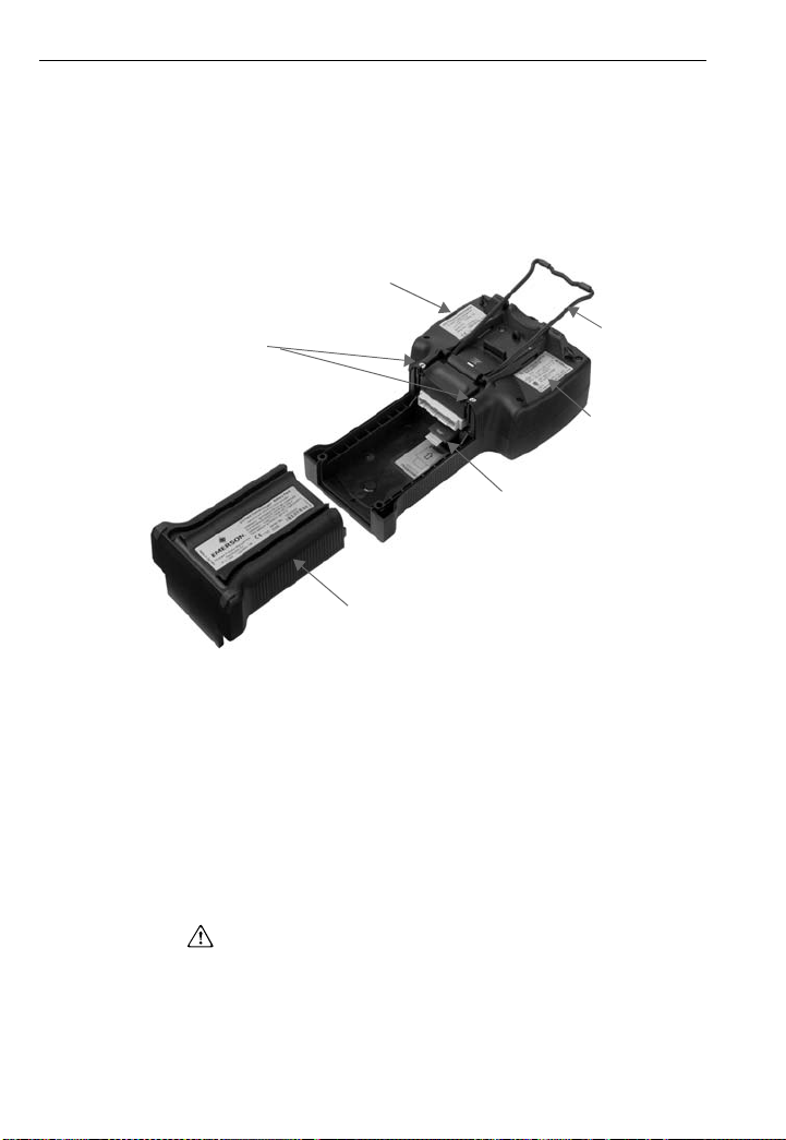
Figure 2-1. Back side of the 375 Field Communicator
1. Place the 375 Field Communicator face down on a
level, secure surface; see Figure 2-1.
2. Lock the stand into the hanger position. To pivot past
the stand position, squeeze the stand together near
the hinge.
Main unit
label
Battery pack
retaining screws
Battery pack
3. With the battery pack removed, place the System
Card, with the card contacts facing up, on the main
unit System Card guide ribs (located directly below
the battery pack connector). Insert the System Card
until it is firmly in place.
4. With the main unit still face down, ensure the tops of
the two battery pack retaining screws are f lush with
the top of the battery pack.
5. Install the battery pack by aligning the sides of the
battery pack and main unit and carefully sliding the
battery pack forward until it is secure. If the battery
pack and main unit are not properly aligned, the
connector pins can be damaged.
6. Tighten the two battery pack retaining screws until
they are secure (do not overtighten). The tops of the
screws should now be close to flush with the stand
groove.
(KL Option)
System Card
Stand
assembly
IS label

Learning the Basics
2-5
STARTING UP
AND
SHUTTING
DOWN
Starting the
375 Field
Communicator
Prior to using the 375 Field Communicator without the
charger/power supply, fully charge the battery pack. A
full charge is indicated by a solid green light on the
charger/power supply. Charging may take up to two
hours, but the 375 Field Communicator may be used
while charging. Before operating the 375 Field
Communicator, ensure:
• The 375 Field Communicator is not damaged.
• The battery pack is fully seated.
• All screws are sufficiently tightened.
• An Expan sion M od ule (EM ) or Ex p a nsi on Port Pl ug is
in place.
• The communication terminal recess is free of dirt and
debris.
Press and hold the on/off/stand by key until the
multifunction LED flashes t o indicat e the unit i s powering
(approximately two seconds). See Figure 2-2 for the
location of the on/off/ st and by key .
During start-up, the 375 Field Communicator will
automatically install any software upgrades available on
the System Card. Once the upgrade is complete, the
375 Main Menu will be displayed. After starting the 375
Field Communicator, you can:
• Launch the HART or F
applications (if licensed)
• Configur e/view s et ting s
• Enter Listen For PC mode
• Launch the ScratchPad application
OUNDATION fieldbus

2-6
Learning the Basics
Entering
Stand By
Shutting Down
the 375 Field
Communicator
The 375 Field Communicator can be put into stand by,
which turns off the display and certain areas within the
375 Field Communicator. Use this opti on to save ba ttery
life or to reduce the boot-up time if you will be using the
375 Field Communicator intermittently.
You can put the 375 Field Communicator in stand by
when the HAR T applic ation or t he Fieldb us appli cation i s
running. If you are working online with a HART or
fieldbus device whe n stan d by is ent ered, the app lication
main menu will be displayed wh en the 375 Field
Communicator returns from stand by. Otherwise, the 375
Field Communicator will display the screen that was
open when stand by was entered.
To enter stand by, press the on/off/stand by key. From
the Power Switch dialog box, tap Stand by and tap OK
or press the enter key. Tap Cancel to close the dialog
box and return to the application. The multifunction LED
will slowly flash a green light when the 375 Field
Communicator is in stand by. To leave stand by, press
the on/off/stand by key.
The 375 Field Communicator will also enter stand by if
the stand by timer has expired. See “Power Status” on
page 2-14 for more i nformation.
To shut down the 375 Field Communicator, press the
on/off/stand by key. From the Power Switch dialog box,
tap Shut down and tap OK or press the enter key. Tap
Cancel to close the dialog box and return to the
application.
Y ou can also shut down the 375 Field Communicator by
simultaneously pressing the backlight adjustment key
and the function key until the display turns off. This is a
mechanism by which the shut down is accomplished in
the hardware (similar to removing the power to a PC
using a switch). This is not the recommended way of
shutting off the 375 Field Communicator.
The 375 Field Communicator will also shut down if the
auto-off timer has expired. See “Power Status” on
page 2-14 for more i nformation.
Learning the Basics
y
t
BASIC
FEATURES
AND
FUNCTIONS
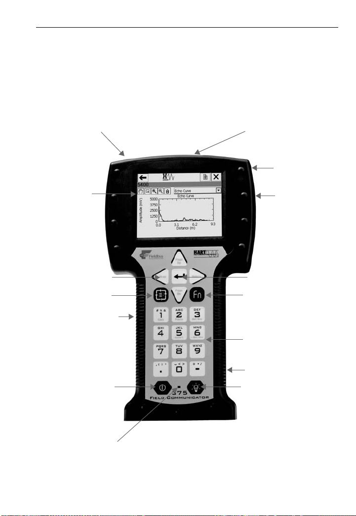
Figure 2-2. 375 Field Communicator diagram
2-7
IrDA interface
Touch screen
Navigation keys
(four arrow keys)
Battery pack (back)
and System Card
On/Off/St a nd by key
(top)
display
Tab key
(internal)
HART and fieldbus
communication
terminals (top)
Stylus
(back)
Expansion por
(side)
Enter key
Function key
(for multiple-key
combination
functionality)
Alphanumeric keypad
Power supply/charger
connection (side)
Backlight adjustment ke
Multifunction LED

2-8
Learning the Basics
Using the
Keypad
The 375 Field Communicator keypad and touch screen
have nearly total functional redundancy.
On/Off/Stand By key
The on/off/st and by key ( ) is used to power on a nd off
the 375 Field Communica tor or to put it in st and by. If the
on/off/stand by ke y i s pres sed when the re is un sent d at a
or a device method is running, a warning message will
appear. Tap OK to have the 375 Field Communicator
enter stand by or shut down, or tap Cancel to return to
the previous screen.
The on/off/stand by key is disabled when the 375 Field
Communicator is in Listen For PC mode or when the
ScratchPad application is open.
Arrow Navigation keys
Four arrow navigation keys let you move through the
menu structure of th e a ppl ic atio ns . Pre ss th e ri ght arro w
key ( ) to select menu item s and to navigate fu rther into
the menu.
Enter key
The enter key ( ) lets you select the focused
(highlighted) item or to complete an editing action. For
example, if you push the enter key when the Cancel
button on a screen is in focus, you will cancel out of that
screen.
The enter key does not allow you to navigate throu gh the
menu structure. Use the arrow navigati on key s or the
stylus to select menu items and to navigate through the
menu structures.
Tab key
The tab key ( ) lets you move between selectable
controls.
Learning the Basics
Alphanumeric keypad
The alphanumeric keypad lets you select letters, digits,
and other characters, such as punctuation marks. It can
perform a selection of options and data entry in either
numeric or alphanumeric modes. The 375 Field
Communicator will automatically determine the mode
depending upon the input necessary for the particular
field.
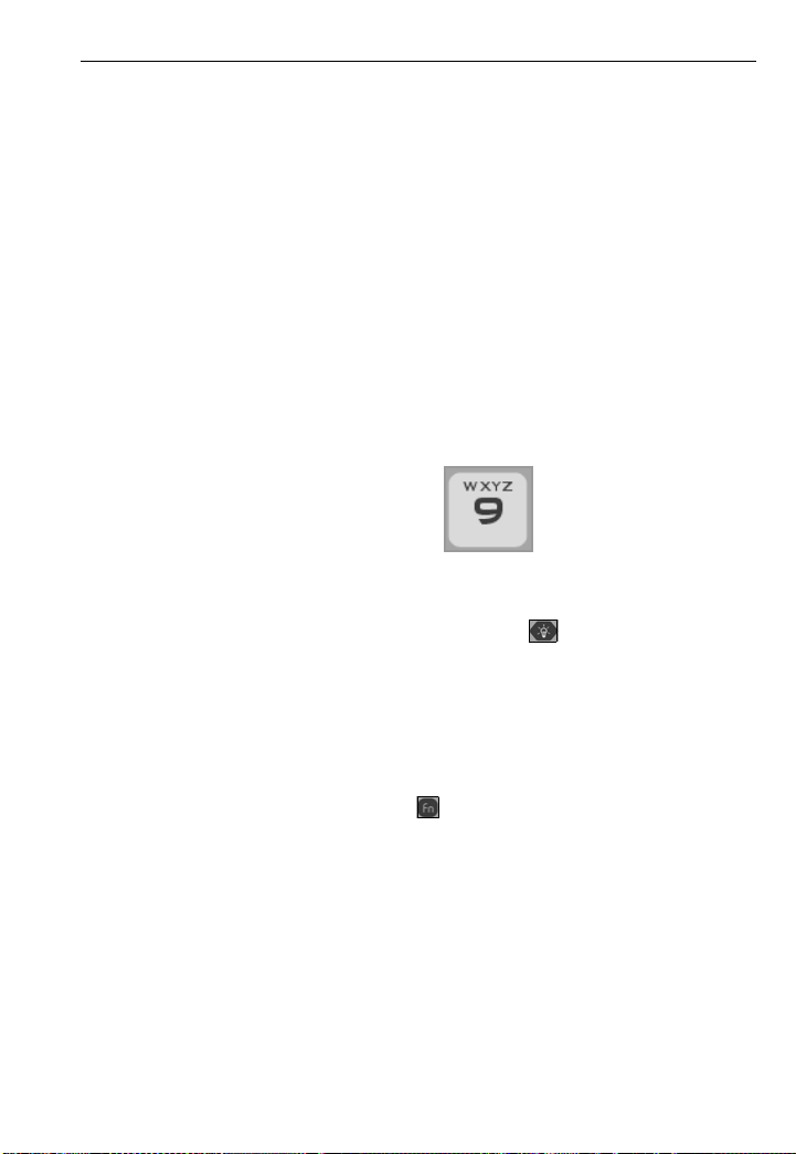
To enter text when in alphanumeric mode, press the
desired keypad button in quick repetition to scroll
through the options to achieve the appropriate letter or
number. For example, to type the letter Z, press the 9
key quickly four times; see Figure 2-3.
Figure 2-3. Keypad button functionality example
Backlight Adjustment key
The backlight adjustment key ( ) lets you adjust the
intensity of the display. There are four different settings.
The intensity impacts the battery life of the 375 Field
Communicator. Expect a shorter battery life for higher
intensities; see “Backlight” on page 2-12 for the settings.
2-9
Function key
The function key ( ) le ts yo u enable alternate
functionality on select keys. The grey characters on the
keys indicate the alternate functionality. When the
function key is enabled, the orange multifunction LED
light will appear and an indication button can be found
on the Soft Input Panel (SIP). Press the function key
again to disable the functionality.
The alternate function on the Tab and alphanumeric 5
key (insert) will be a ctivated in future re lease s of th e 375
Field Communicator software.

2-10
Multifunction LED
The multifunction LED lets you recognize when the 375
Field Communicator is in v arious states; see Table 2-1.
Table 2-1. Multifunction LED
Multifunction LED Processing indication
Solid green The 375 Field Communicator is on.
Flashing green The 375 Field Communicator is in
Solid green and orange The function key is enabled.
Blink green and orange The on/off/stand by key has been held
Learning the Basics
power saving mode (stand by). The
display is off.
down long enough for power up.
Using the
Touch Screen
The touch screen display lets you select and enter text
by touching the windo w . Tap the window once to select a
menu item or to activate a control. Double-tap to move
further into the menu level.
NOTE
All instructions in this manual are written for the touch
screen.
The touch screen should be contacted by blunt items
only, preferably the stylus includ ed with the 375 Field
Communicator. Using sharp instruments, such as
screwdrivers, can cause failure of the touch-screen
interface. Repair of the touch screen requires
replacement of the entire 375 Field Communicator
display assemb ly , whic h is poss ible only a t an author ized
service center.
Use the back arrow icon ( ) to return to the previous
menu. Use the terminate icon ( ) in the upper right
corner of the touch screen to end the application.
Use the Soft Input Panel (SIP) keyboard
The SIP keyboard allows for alphanumeric input using
the touch screen. The SIP keyboard detects when you
need to enter characters and will appear automatically
as required.
Learning the Basics
2-11
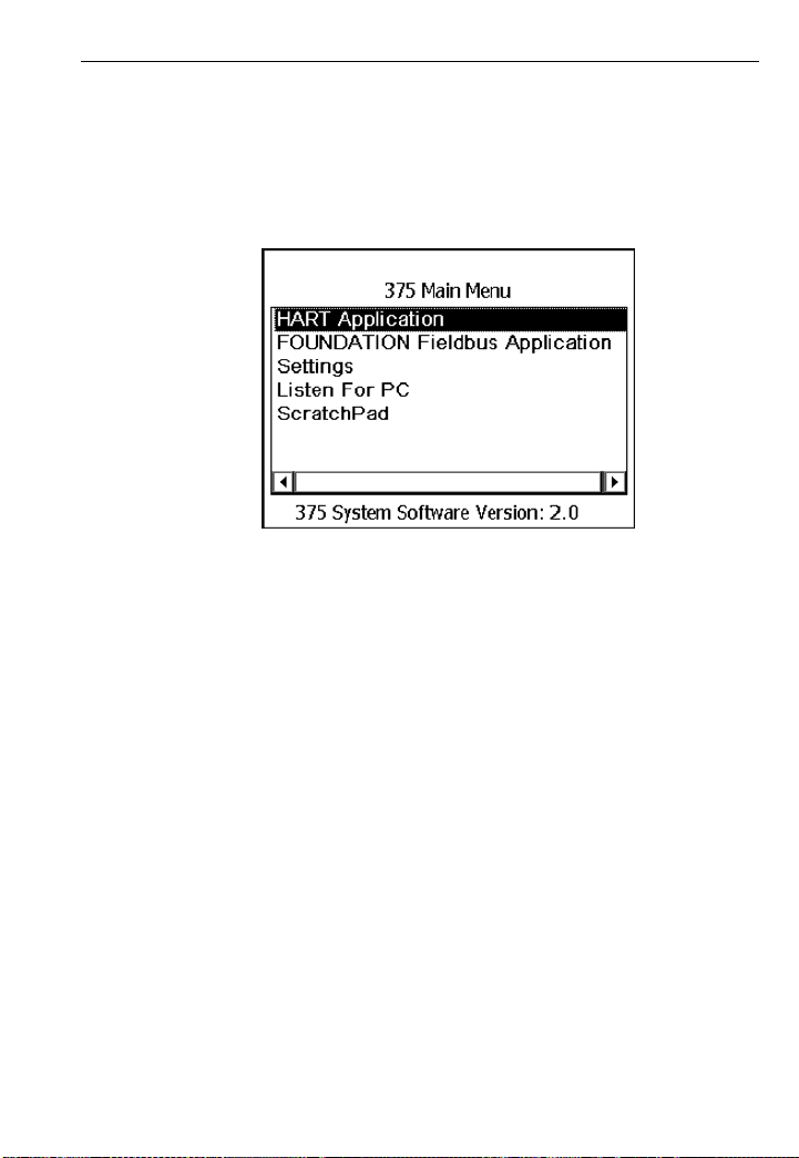
THE 375 MAIN
MENU
Figure 2-4. 375 Main Menu example
Starting the
HART
application
Starting the
Fieldbus
The 375 Main Menu lets you run the HART applica tion,
run the F
Settings menu, communicate with a PC, and launch the
ScratchPad application .
From the 375 Main Menu, double-tap HART
Application to run the HAR T applicati on. On st artup, the
HART application will automatically poll for devices.
From the 375 Main Menu, double-tap FOUNDATION
Fieldbus Application to run the Fieldbus application.
OUNDATION Fieldbus application, run the
application
Running the
Settings menu
From the 375 Main Menu, double-tap Settings to view
the Settings menu. The Settings menu lets you set
preferences for the 375 Field Communicator and view
system properties and license information.

2-12
Learning the Basics
About 375
About 375 lets you view the software property revisions
of your 375 Field Communicator. If you need to call
technical support personnel, have the sy stem software
version, Communication and Diagnostic Circuitry (CDC)
version, and the operating system version on hand.
Launching RE-FLASH initiates the reinstallation of the
firmware and software from the System Card. The 375
Field Communicator must be running on external power
when the RE-FLASH operation i s pe rformed . Durin g the
operation, the stand by and auto-off timers will be
disabled. This oper ation should o nly be performed under
the direction of technical support personnel.
Launching RE-IMAGE will re-install the operating
system, system software, and applications on your 375
Field Communicator. The 375 Field Communicator must
be running on external power when the RE-IMAGE
operation is performed. During the operation, the stand
by and auto-off timers will be disabled. This operation
should only be performed under the direction of
technical support personnel.
Tap OK to return to the Settings menu.
Backlight
The backlight setting lets you adjust the intensity of the
display. To adjust the backlight, drag the slider left to
right.
The backlight setting also lets you set timers to
automatically turn off the backlight after a specified
period of inactivity. These timers apply when the 375 is
running on battery power or external power. Turning off
the backlight after periods of inactivity will save battery
power. To enable a timer, click a drop-down menu and
select the appropriate time interval.
When you have selected the appropriate backlight
settings, tap OK to retain this setting for this session
only, SET DEFAULT to retain this setting upon start up,
or CANCEL to exit without changes.

Learning the Basics
2-13
Clock
The clock setting lets you set the date and time on the
375 Field Communicator. Configure the date by using
the drop-down menu. To configure the time, high light the
appropriate time field and use the arrows to scroll
through values until you fin d the c orre ct ti me . Sele ct OK
to save the changes and to close the window, or
CANCEL to exit without changes.
Contrast
The contrast setting lets you adjust the lightest and
darkest areas on a display screen.
To adjust the contrast, drag the slider to the left or right.
The window will auto ma tic ally adjust the cont rast as you
move the slider. When you find an appropriate contrast
setting, tap OK to retain t his s ett ing fo r th is s es sio n onl y,
SET DEFAULT to retain this setting upon start up, or
CANCEL to exit without changes.
NOTE
Temperature can affect contrast.
License
The license s etting l ets y ou view the e nabled l icenses on
the System Card. The HART application license is
standard in every 375 Field Communicator. Other
licenses available inc lude the F
application, Easy Upgrade option, and the Graphics
option. Unlicensed features cannot be accessed.
The License screen also displays the System Card
Serial Number (SN) and the unit name of the 375 Field
Communicator. A unit name can be assigned by using
the Easy Upgrade Programming Utility. See the
Programming Utility onlin e Help for more det ails. Tap OK
to return to the Settings menu.
OUNDATION fieldbus
Memory
The memory setting let s you v iew availa ble free sp ace in
the System Card, Internal Flash, RAM, and Expansion
Module (if installed).

2-14
Learning the Basics
Power Status
The power status setting lets you specify power
management options for when the 375 Field
Communicator is running on battery power. To specify
values for the stand by or auto-off timers, select the time
intervals from the drop-down menus. Af ter the sp eci fie d
periods of inactivity, the stand by timer will put the 375
Field Communicator in stand by mode, or the auto-off
timer will turn off the 375 Field Communicator. If set to
short intervals, these timers will save battery power.
The Maximize Power Savings option conserves
additional battery power by allowing the 375 Field
Communicator to enter stand by mode or shut down
when communicatin g with a devic e. To enable Maximize
Power Savings, tap the checkbox and a checkmark
appears. If this option is disabled, the 375 Field
Communicator will not ente r stan d by or shut dow n when
communicating with a device.
The Maximize Power Savings option applies only when
the 375 Field Communicator is communicating with a
device. If it is not communicating with a device, the 375
Field Communicator will enter stand by or shut down
when the timer expires, independent of the Maximize
Power Savings option. This can occur when viewing
certain menus, such as the Settings menu or an
application main menu.
When you determine the appropriate power
management settings, tap OK to apply the settings for
this sessio n only, SET DEFAULT to retain the settings
upon start up, or CANCEL to exit without changes.

Learning the Basics
2-15
Retrain the Battery
The retrain the bat tery sett ing let s you fully dis charge th e
battery so it can be charged to its full capacity. Perform
this operation if you notice a decrease in battery life or
every three to six months as a best practice. Ensure the
375 Field Communicator is running on battery power
when this operation is performed.
During the operation, a message will be displayed and
the backlight will be set to its brightest setting to quickly
discharge the battery. The backlight, stand by, and
auto-off timers will be disable d. It may t ake up to severa l
hours to discharge the battery, depending on the amount
of battery power that remained when the operation
began.
If you tap CANCEL, the battery will stop disc harging and
the backlight, stand by, and auto-off timers will be
re-enabled. The backlight setting will also be restored.
After the battery is fully discharged, do not use the 375
Field Communicator on battery power until it has been
recharged to its full capacity. However, you can use the
375 Field Communicator while it is being charged.
Touch Screen Alignment
The touch screen alignm ent settin g let s you ca librate the
touch screen with the display. Tap the cross hairs firmly
and accurately at each location on the window. The
target will continue to move until the touch screen is
aligned. Touch screen alignment will be retained upon
start up.

2-16
Learning the Basics
Event Capture
The event capture setting lets you create an event
capture file (.rec), which i s a log of c ommunication , input,
and screen output that occurs between the 375 Field
Communicator and a device (HAR T only). When working
with technical support personnel, you may be asked to
create an event capture file to help troubleshoot issues
that cannot be isolated or resolved by nor m al means.
The event capture file can then be transferred to your
PC and sent to technical support personnel for review.
Tap the desired radio button to activate the event
capture feature. The radio button will be highlighted
black when selec ted. To delete an eve nt cap ture, ta p the
DELETE EVENT FILE button.
NOTE
While event capture is enabled, device warning
messages will not appear.
To create and send an event capture file to technical
support personnel:
1. Enable event captures and tap OK.
2. Start the HART application.
3. Enter a file name for the event capture file and tap
OK. The file will be saved to a default location.
4. Perform the requested operations to capture the data.
5. Use the Easy Upgrade Programming U tility to transfer
the file from your 375 Fie ld Communi cator to you r PC.
See the Easy Upgrade Programming Utility online
Help for details.
6. Send the event capture file to technical support
personnel.
Exit to 375 Main Menu
Double-tap Exit to 375 Main Menu if you want to return
to the 375 Main Menu.

Learning the Basics
2-17
Communicating
with a PC
IrDA
The 375 Field Communicator can communicate with
PCs using infrared technology. IrDA is a PC interface
supported for the transfer of device descrip tio ns ,
software updates, configurations, event captures,
application licenses, and ScratchPad files.
IrDA communication can eithe r be built into the PC , such
as a laptop, or provided through an adapter such as a
USB to IrDA adapter. Refer to your IrDA manual for
installation and operating instructions.
Throughput for infrared communications with the 375
Field Communicator is approximately
4 kilobytes/second. The maximum recommended
distance between the IrDA and PC is 18 inches.
Card Readers
The 375 Field Communicator can also communicate
with PCs using a USB Secure Digital card reader. Insert
the 375 System Card into a card reader, and system
software upgrades and device descriptions can be sent
to the System Card using the Easy Upgrade option.
When downloading a large system software upgrade or
many device descriptions, a card reader may be
required.
NOTE
Using Windows Explorer and a card reader to transfer
files between the Sys tem Card and a PC ca n corru pt the
System Card. This operation should only be performed
under the direction of technical support personnel.
The card reader will pro vide faster uplo ad and dow nload
speeds than an IrDA adapter , ho wever , it ca nnot be used
to transfer licenses, event capture files, or user data
files. See the Easy Upgrade Programming Utility online
Help for details.
NOTE
The instructions in this manual are written for using the
IrDA connection, not the card reader.

2-18
Learning the Basics
Listen For PC
In Listen For PC, the 375 Field Communicator is under
the control of a PC application for transferring data and
managing device configurations. The PC application
could be one of the following:
• AMS™ Suite: Intel ligent Device Manager (v ers ion 6.2
or higher), software for mana ging instrum entati on and
valves in a process plant. Currently, AMS Device
Manager supports HART configurations only.
• 375 Easy Upgrade Programming Utility
NOTE
The on/off/stand by key, and the stand by and auto-off
timers are disab led wh en th e 375 Fi eld Co mmun icato r is
in Listen For PC mode.
The 375 Field Communicator must be in Listen For PC
mode when communicating through IrDA.
To enter Listen For PC:
1. From the 375 Main Menu, select Listen For PC. A
warning message will appear if the 375 Field
Communicator is running on battery power when you
select Listen For PC. Click OK to proceed and enter
Listen for PC mode. The Listen For PC screen
displays the unit name and System Card Serial
Number.
2. Align the 375 Field Communicator IrDA interface with
the PC IrDA interface.
3. Complete the necessary transfer(s) using the Easy
Upgrade Programming Utility or AMS Device
Manager. See the Easy Upgrade Programming Utility
online Help for more information.
4. Tap EXIT to close the Listen For PC application.
If new system sof tware was downloade d to the 375 Field
Communicator System Card, an update of the Internal
Flash will occur upon exit.

Learning the Basics
2-19
Transfer HART Configurations using
AMS Suite: Intelligent Device Manager
A Handheld Communicator Interface kit of the AMS
Device Manager (version 6.2 or higher) option lets you
use the 375 Field Communicator with AMS Device
Manager.
To transfer HART configurations:
1. Align the 375 Field Communicator IrDA interface with
the PC IrDA interface, and enter Listen For PC m od e.
A 375 Field Communicator icon will appear in AMS
Device Manager to indicate that all configurations
from the 375 Field Communicator can be accessed.
2. In AMS Device Manager, double-click the 375 Field
Communicator icon. The Expansion Module and
Internal Flash folders are displayed. Once all of the
configuration files are displayed, perform your tasks
with AMS Device Manager.
Easy Upgrade Programming Utility
To add device descriptions (DDs), system software
upgrades, or lice ns es, you need a System Card wi th t he
Easy Upgrade option. All 375 Field Communicators
come with the basic a bility to tran sfer event cap tures and
user data (text) files using the Easy Upgrade
Programming Utility. You can also assign a unit name to
a 375 Field Communicator to uniquely identify it. For
more details on use, see the Easy Upgrade
Programming Utility online Help.
Using the
ScratchPad
application
From the 375 Main M enu, d ouble-t ap ScratchPad to run
the ScratchPad application. ScratchPad is a text editor
that you can use to create, open, edit, and save simple
text (.txt) documents. You can transfer text files between
a PC and the 375 Field Communicator using the Easy
Upgrade Programming Utility. ScratchPad supports very
basic formatting. You can also launch the ScratchPad
application from within the HAR T or Fiel dbus ap plica tion
by tapping the ScratchPad ( ) icon in the upper right
corner of the display. This will automatically open the
ScratchPad application .
2-20
NOTE
The on/off/stand by key, and the stand by and auto-off
timers are disabled when the ScratchPad application is
open.
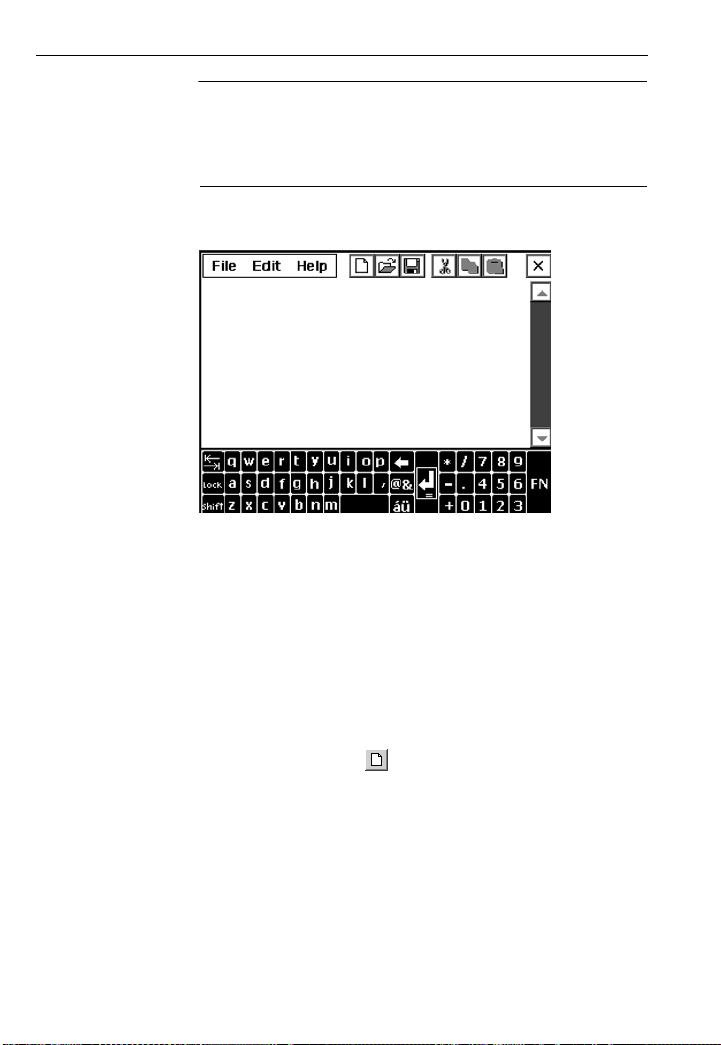
Figure 2-5. Open blank document in ScratchPad
Once ScratchPad is launched, you can perform the
following operations:
Create a New Document
From the Main Page in the ScratchPad application, tap
the NEW button. An empty text window and SIP keypad
will appear. You are now ready to enter text into your
new document.
A new document can also be cre ated within ScratchPad
by tapping the New ( ) icon in the toolbar or by
selecting File | New from the menu.
Learning the Basics
Open an Existing Document
1. From the Main Page in the ScratchPad application,
select the desired file located under File Name.
2. Tap the OPEN button. A text window and the SIP
keypad will appear. You are now ready to edit your
document.
 Loading...