

Page 1
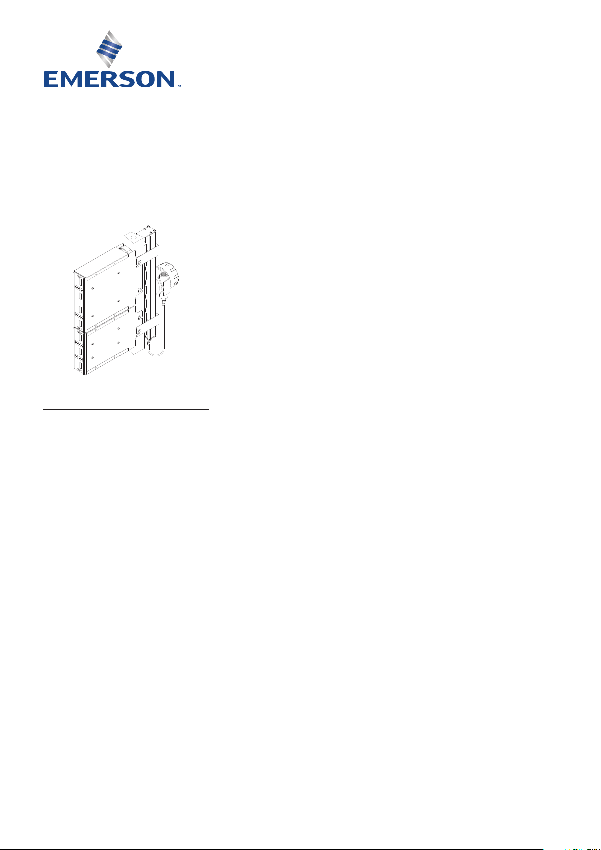
YARWAY LED ILLUMINATOR SYSTEM FOR COLOR-PORT GAUGES
INSTALLATION, OPERATION AND MAINTENANCE INSTRUCTIONS
Before installation, these instructions must be carefully read and understood.
Tables and figures
Table 1 - Model structure................................. 3
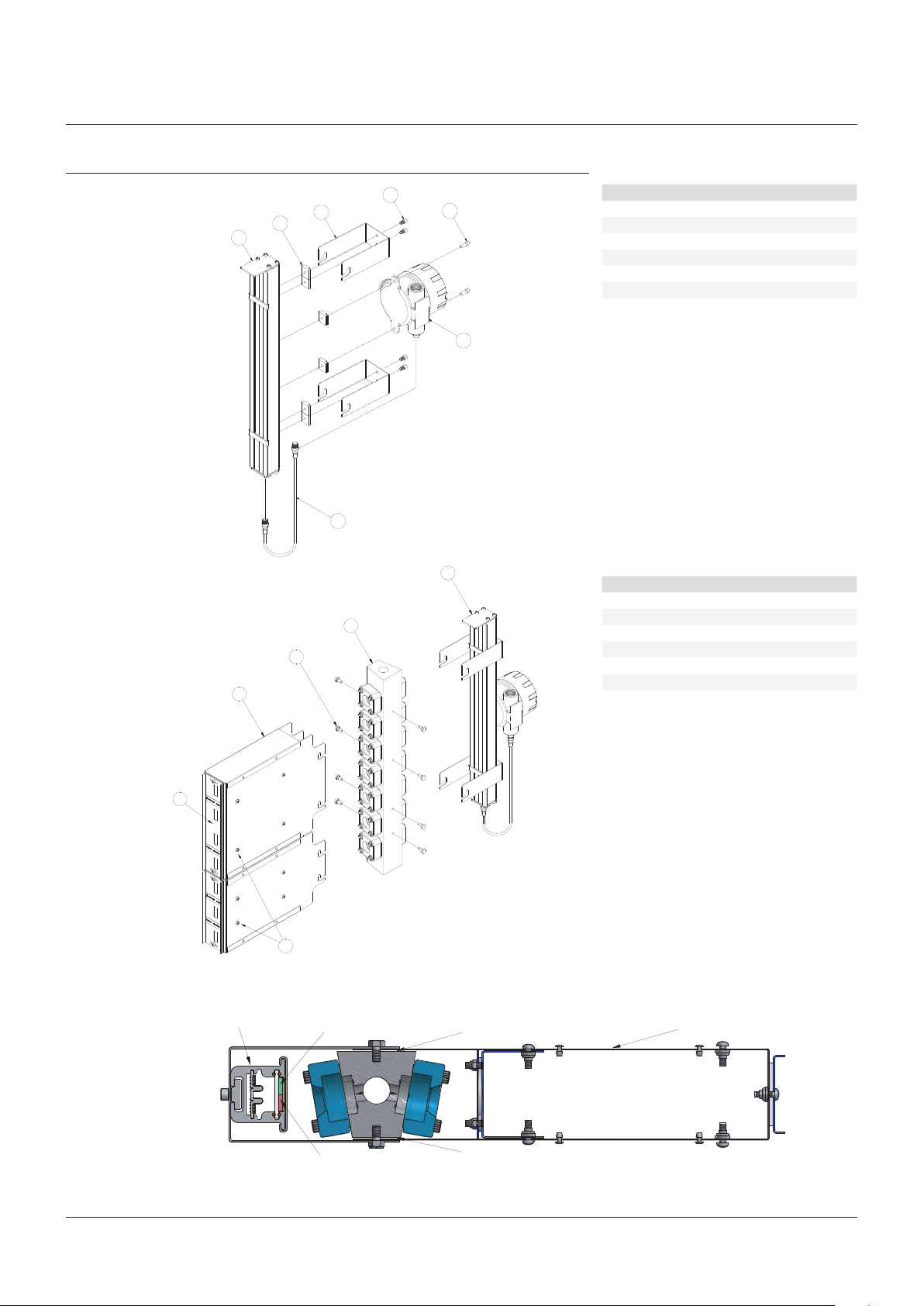
Figure 1 - Exploded parts diagram ................... 7
Figure 2 - Installation of LED illuminator and
TABLE OF CONTENTS
1 Safety information ................................... 1
2 Introduction ............................................. 2
2.1 System description ...................................... 2
2.2 Accessories .................................................. 2
3 Available models ..................................... 2
3.1 Power requirements and specifications .... 2
3.2 Approvals ..................................................... 2
4 Inspection ................................................ 4
5 Installation ............................................... 4
5.1 Inspection and cleaning of glass ................ 4
5.2 Assembly - pre-installation ........................ 4
5.3 Installation of unit to gauge ........................ 4
5.4 Electrical installation ................................... 5
6 Operation ................................................. 5
7 Maintenance ............................................ 5
7.1 Preventative maintenance ........................... 5
7.2 Maintenance procedures ............................ 5
7.3 Troubleshooting ........................................... 5
7.4 Allowable modifications .............................. 5
8 Removal - disassembly - reassembly ..... 6
8.1 Disassembly ................................................. 6
8.2 Reassembly .................................................. 6
9 Packaging, storage and transportation ... 6
9.1 Packaging ..................................................... 6
9.2 Storage ......................................................... 6
9.3 Transporation ............................................... 6
10 Disposal at end of useful life ................... 6
11 Warranty .................................................. 6
12 Telephone assistance .............................. 6
13 Exploded parts diagrams......................... 7
level display to color-port gauge ........
Figure 3 - Red/green colored glass orientation ... 7
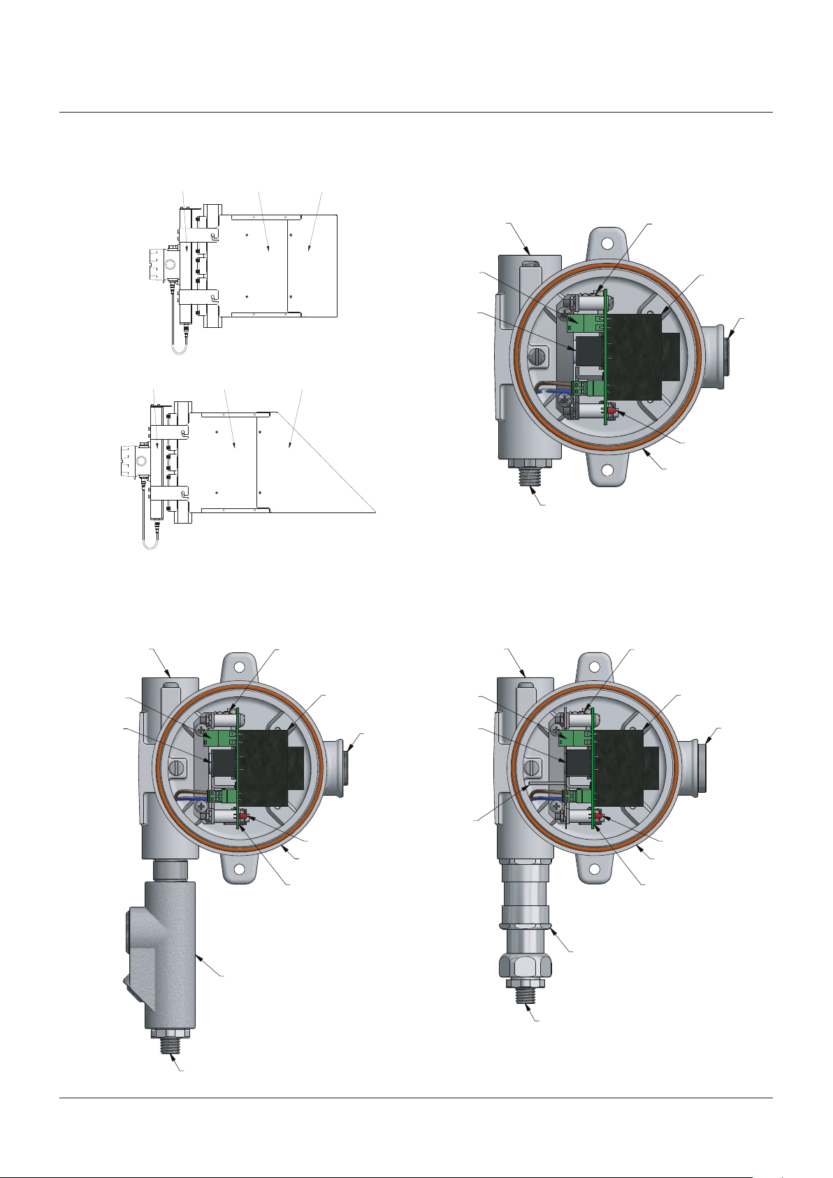
Figure 4 - Accessories views ............................. 8
Figure 5 - Wiring installation ............................. 8
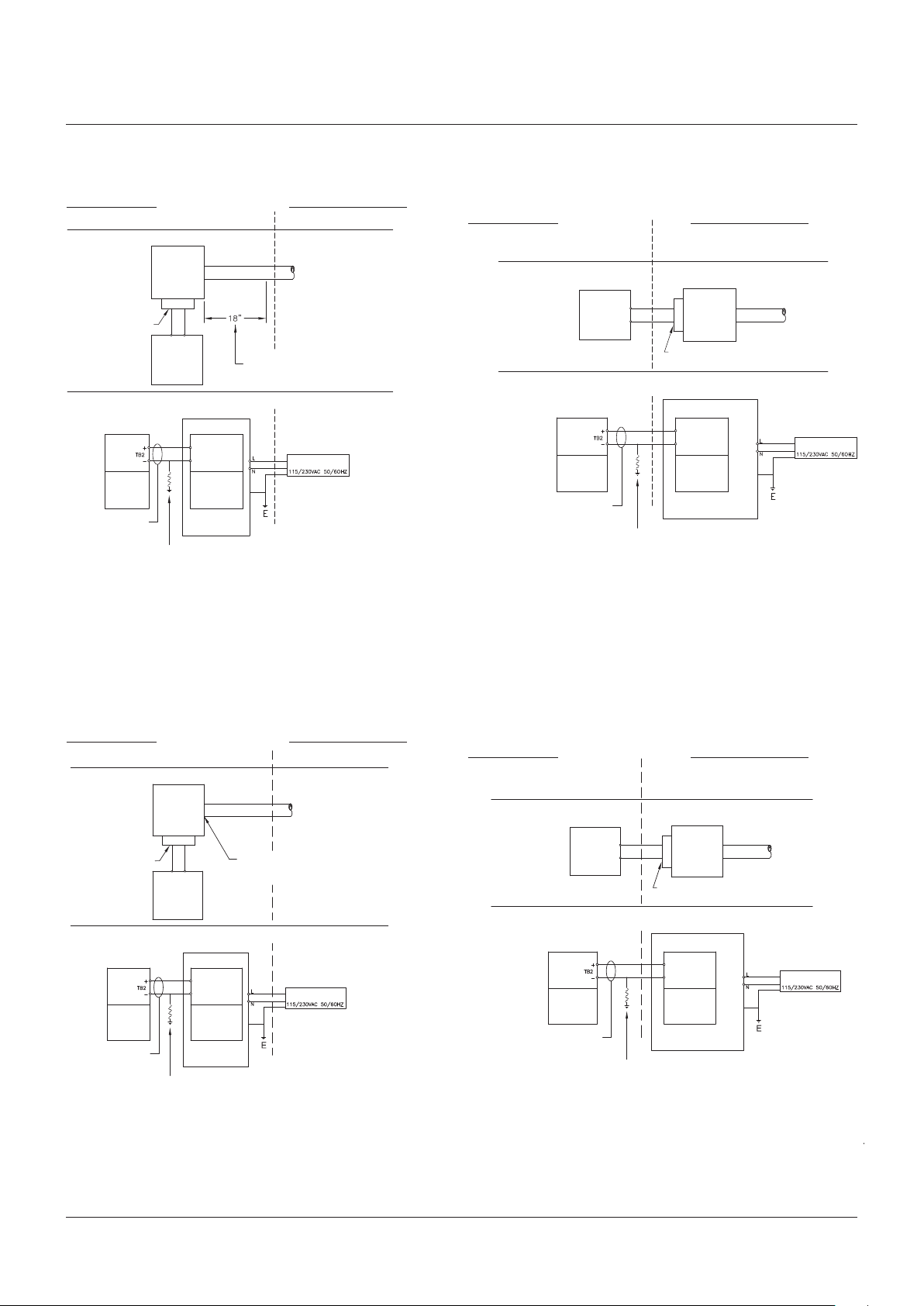
Figure 6 - Control drawings ............................... 9
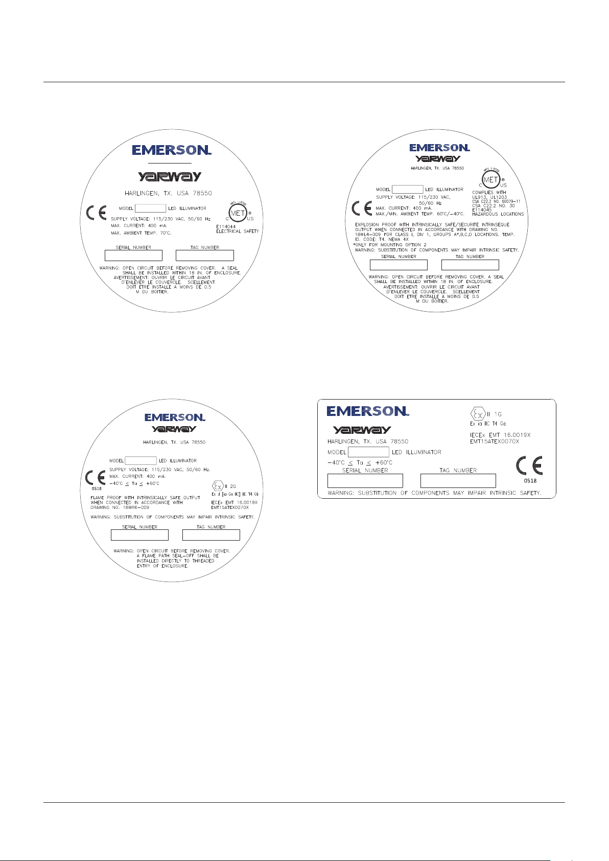
Figure 7 - Nameplates ..................................... 10
1 SAFETY INFORMATION
IMPORTANT
It is the user's responsibility to ensure that all
connections and wiring comply with all applicable
codes, specifications, sales contracts or public laws.
IMPORTANT
The sales order lists the required operating
voltage. Operation at a voltage other than
specified will cause equipment damage.
The Color-Port gauge operates at the
boiler saturation temperature. High surface
temperatures can be expected where this
equipment connects to the gauge.
WARNING
Do not touch until the unit has cooled.
The Color-Port gauge must be adequately
supported to hold the combined weight of LED
illuminator, level display and hood (if applicable).
Shut-off LED illuminator before doing any
maintenance or repairs.
7
Emerson.com/FinalControl
© 2017 Emerson. All Rights Reserved. VCIOM-04070-EN 19/10
Page 2

YARWAY LED ILLUMINATOR SYSTEM FOR COLOR-PORT GAUGES
INSTALLATION, OPERATION AND MAINTENANCE INSTRUCTIONS
2 INTRODUCTION
Yarway LED illuminators are designed to be
mounted readily to the Yarway Color-Port gauge,
as well as most competitive color-port gauges.
All illuminators are complete with a color
screen containing two strips of glass - one red
and one green. Due to the difference in the
index of refraction of light through water and
steam, only the corresponding color is seen:
green for water, red for steam.
Yarway LED illuminators are available in lengths
from 5 ports to 26 ports.
2.1 System description
Yarway LED illuminators comprise five main
components. Use the exploded parts diagrams in
Section 13 as additional reference material.
Illuminator - light source. It is composed of
an anodized, rigid, extruded aluminum that
protects the PC boards.
Bracket - used to mount illuminator to ColorPort gauge. The brackets can be moved up
and down along the extruded body making
assembly and disassembly quick and easy.
Power supply - provides intrinsically safe
power to the LED illuminator. Power supply is
mounted inside an explosion proof enclosure
that is mounted to the illuminator body.
Cordset - used to connect the power supply
to the illuminator. The cordset consists of a
straight female connector and a straight male
connector.
3 AVAILABLE MODELS
Yarway LED illuminators are made to fit/cover
the whole length of the Color-Port gauge. One
power supply is required per 26 ports (208LEDs).
On average an LED will give the user 100,000
hours of use compared to 1000 hours for a
standard light bulb.
3.1 Power Requirements & Specifications
Input: 115/230 VAC ±10%, 50/60 Hz
Power consumption: up to 400 mA max at
115/230 VAC
Max distance from power supply to LED
illuminator: 200 ft. (consult Emerson if longer
distance is required)
Ambient temperature range for general
location: -40°F to 158°F (-40°C to 70°C)
Ambient temperature range for hazardous
location: -40°F < ta < +140°F (-40°C < ta < +60°C)
Ingress protection: IP66
Max altitude: 6.561 ft.
Electrical connection size:
¾” FNPT for US and Canada
M20 for ATEX and IECEx
• Unit must be wired with 14 AWG wire
minimum, with a maximum wire length of
1000 feet.
• An external switch or circuit-breaker
and external overcurrent protection is
recommended to be installed near the unit.
• Unit can be use indoors and outdoors.
• Maximum relative humidity 80% for
temperatures up to 88°F (31°C) decreasing
linearly to 50% relative humidity at 104°F
(40°C).
WARNING
Do not tamper with Yarway's power supply
or its components.
3.2 Approvals
General location
UL61010-1/CSA C22.2 No. 61010-1
Explosion-proof with intrinsically safe output
MET Certified for US and Canada
Class I Division 1 Groups A*, B, C, D T4
* only for Mounting Option 2
ATEX Approved
II 2G (Power Supply)
II 1G (Illuminator)
IECEx Approved
Ex d [ia Ga IIC] IIC T4 Gb (Power Supply)
Ex ia IIC T4 Ga (Illuminator)
When installed in accordance with Emerson
Control Drawings:
• For Division Locations - 18WL4-009 (Figure 6A)
• For ATEX/IECEx - 18WR6-009 (Figure 6B)
Level display - focuses the light from the LED
illuminator to show the level.
2.2 Accessories
Level display hood and hooded mirror enhance the images for outdoor installations or
redirect the image for viewing below the gauge.
2
Page 3

YARWAY LED ILLUMINATOR SYSTEM FOR COLOR-PORT GAUGES
INSTALLATION, OPERATION AND MAINTENANCE INSTRUCTIONS
TABLE 1 - MODEL STRUCTURE
Example: ILCP 25 05 1 G S
Illuminator model
ILCP Illuminator LED Color Port
Port spacing
25 2.5” pitch
28 2.875” pitch
Illuminator size (gauge size)
Number of ports (05 – 26)
Input voltage
1 115 VAC 50/60 Hz (¾ NPT inlet)
2 230 VAC 50/60 Hz (M20 inlet)
3 115 VAC 50/60 Hz (M20 inlet)
4 230 VAC 50/60 Hz (¾ NPT inlet)
Application location
G General locations
D Division locations (MET for US and Canada)
Z Zone locations (ATEX and IECEx)
Installation configuration
S Standard
C Chain connection (staggered gauges)
R Remote mount power supply
A Chain connection (staggered gauges) and remote
mount power supply
Conditions of Use for Ex Component
1 Tserv according to use seal:
TPE: -40÷100/85°C - lower temperature for housing with sight glass
VMO: -40÷100/85°C - lower temperature for housing with sight glass
FKM: -20÷200/85°C - lower temperature for housing with sight glass
2 Max number, size and position of apertures - are given in Application manual N-L2237 dated 31.03.2016
3 For information on the dimensions of the flameproof joints the manufacturer shall be contacted.
4 Apparatus installed inside of enclosure can have any lay-out, which ensures that in any cross section
area will be at least 40% (group IIC) of area free
5 The enclosure with Ex component certificate can be applicate only by assumption of filling requests of
the standard IEC 60079-1:2014, cl. D.3.10
6 Appropriately certified cable glands for direct entry have to be used
7 IP 68 max (h=1 m)
8 The max overpressure static test of housing: 50 bar/10 s
9 Max power dissipation for temperature class, see ANNEX to IECEx Certificate No. IECEx FTZU 12.0017U
Issue No. 0
3
Page 4

YARWAY LED ILLUMINATOR SYSTEM FOR COLOR-PORT GAUGES
INSTALLATION, OPERATION AND MAINTENANCE INSTRUCTIONS
4 INSPECTION
Safety instructions
Exercise care in handling illuminator parts to
avoid scratching, denting or otherwise damaging
the protective glass. Any marks on the protective
glass, as well as dirt, paint or tape will result
in a reduction of light output. On receipt of an
illuminator, check all components carefully
for damage incurred in shipping. If damage is
evident or suspected, do not attempt installation.
Notify the carrier immediately and request a
damage inspection. Refer to the exploded view
drawing in Section 13 to inventory parts.
5 INSTALLATION
Installation should only be undertaken by
qualified personnel who are familiar with
this equipment. They should have read and
understood all of the instructions in this
manual. The user should refer to relevant
technical data sheets or the product proposal
to obtain dimensional information for the
specific size and model illuminator.
It is the user’s responsibility to assure that
knowledgeable installation personnel plan and
carry out the installation in a safe manner.
The following procedures are some of the
guidelines that should be employed:
5.1 Inspection and cleaning of glass
Prior to installation of an illuminator to a
gauge, the gauge glass should be cleaned and
inspected per instructions as follows:
1. Clean glass within vision ports using a nonabrasive household cleaner. DO NOT use a
wire brush, metal scraper or any device which
could scratch the glass.
2. Inspect the surface of the glass for any signs
of clouding, etching, scratching or physical
damage such as bruises, chips or erosion
that penetrates the outer surface of the
glass. Shining a light at approximately a 45º
angle will aid in detecting some of these
conditions. Light will glisten more brightly
on glass imperfections than the surrounding
glass when reflecting light. Detection of
any such problem areas or surface wear
is sufficient evidence of damage. Do not
proceed with installation with damaged glass.
See appropriate Installation, Operation and
Maintenance manual and replace glass.
2. Check that the level display adjustment
plate (164) is oriented with view slots
towards the wide side of the gauge.
5.3 Installation of unit to gauge
Become familiar with the illuminator components
before proceeding with installation. Refer to the
exploded parts drawing in Section 13, Figures 1
and 2. As well as Figure 5A for general locations,
Figure 5B for division locations, and Figure 5C
for ATEX/IECEx when performing the following
installation instructions.
To assemble the illuminator and level display to a
Color-Port style gauge, follow the steps below:
1. Mount level display to gauge by inserting
mounting slots to the hex screws on the
body of the gauge.
2. Attach the mounting brackets (73A) to the
illuminator body (11) using the screws (100)
and the slider brackets (73) provided. Leave
two slider brackets in the middle-lower half
of the illuminator for the power supply.
3. Align the mounting brackets with the mark
on the back of the illuminator’s body.
4. Firmly tighten down the screws (100)
to secure mounting brackets (73A) to
illuminator body.
5. Mount LED illuminator to gauge by inserting
mounting brackets to the hex screws on the
body of the gauge.
6. Make sure that the LED clusters are aligned
with the ports.
7. Firmly tighten down the hex screws on the
gauge body to hold the illuminator and the
level display to the gauge.
8. Open the cover of the power supply
enclosure and make sure the AC input
voltage selector switch in the power supply
matches the input voltage provided to the
unit (115 VAC or 230 VAC).
9. After voltage selector switch is selecting the
correct input voltage, connect/plug in the AC
wires to Terminal Block 1.
10. Fully close the cover of the enclosure by
hand tightening it.
11. Mount power supply to the illuminator body
using the last two slider brackets you set
aside from step 2.
12. Connect the power supply to the LED
illuminator using the cordset provided.
IMPORTANT FOR HAZARDOUS LOCATION
ONLY
• A flame path seal-off shall be installed within
18 in. of enclosure. see Figure 5B for Division
Locations.
• A flame path seal-off shall be installed directly
to threaded entry of enclosure. see or Figure 5C
for ATEX/IECEx.
• The LED Illuminator contains material
composition capable of igniting the explosive
atmosphere due to physical impact or friction.
Installation shall provide inherent protection
from potential impacts risks by means of
installation location, guards and/or barriers.
5.2 Assembly - pre-installation
1. Check the orientation of the red/green
glass. The green glass must be towards the
wide side of the gauge (see figure 3)
1.1 If colored glass is orientated correctly no
action is required
1.2 If colored glass is not oriented correctly
the LED illuminator must be mounted up
side down. See 5.3 Installation of unit to
gauge for mounting instructions.
4
Page 5

YARWAY LED ILLUMINATOR SYSTEM FOR COLOR-PORT GAUGES
INSTALLATION, OPERATION AND MAINTENANCE INSTRUCTIONS
5.4 Electrical installation
WARNING
DO NOT proceed with electrical installation unless
the illuminator has been mounted to the gauge
according to instructions in Section 5.3. Only
qualified electricians who have read and understood
local and national electrical codes should connect
the illuminator to an electrical source. Failure to
follow any of these instructions may result in death,
severe personal injury, property damage or damage
to the illuminator and gauge.
The electrical installation should be performed
by a qualified electrician and comply with
applicable codes (U.S. - refer to National
Electrical Code NFPA current edition;
Canada - refer to Electrical Code CSA C22) or
other regulations as applicable. The conduit
must run in such a manner that it is not
supported by or does not serve as a support
for the illuminator. The unit must be grounded
before it is operated.
6 OPERATION
Check that all installation procedures
have been completed. Use only qualified,
experienced personnel who are familiar with
illuminators and thoroughly understand the
implications of all the instructions. If the
equipment is used in a manner not specified by
the manufacturer, the protection provided by
the equipment may be impaired.
7.2 Maintenance procedures
Cleaning the protective glass/colored glass-
wash with a non-abrasive soap or detergent
and water using a soft, grit-free cloth or
sponge. When cleaning grease and oil from the
protective glass/colored glass, use a chemical
compatible with silicone rubber only and a soft,
grit-free cloth. DO NOT use solvents such as
acetone, benzene, carbon tetrachloride, dry
cleaning fluid or lacquer thinners since they
will attack the surface of the protective glass/
colored glass and or the gaskets. After the
surface has been cleaned and rinsed of foreign
particles, it may be dried with a clean, soft,
damp chamois or grit-free cloth.
IMPORTANT
DO NOT use hard, rough cloths on the edge of
protective glass/colored glass because they can
scratch the surface. The scratches will result in
reduced light output from the illuminator.
7.3 Troubleshooting
Internal or external corrosion - could be an
indication of a harsh service environment. An
investigation should be carried out immediately
to determine the cause of the problem. It is the
user’s responsibility to choose a material of
construction compatible with both the contained
fluid and the surrounding atmosphere.
All LEDs off - could be an indication of
power failure. Check the power supply and
connections.
7 MAINTENANCE
The user must create maintenance schedules,
safety manuals and inspection details for each
specific installation of an illuminator.
7.1 Preventative maintenance
On all installations the following items should
be evaluated regularly by the user for purposes
of maintenance:
1. Protective glass/colored glass, for signs of
dirt build up, scratches or breakage
2. Mounting bracket for signs of loosening
The user must determine an appropriate
maintenance schedule necessary for his or
her specific application, upon evaluation of
their own operating experience. Realistic
maintenance schedules can only be determined
with full knowledge of the services and
application situation involved.
IMPORTANT
Contact the manufacturer if any part needs to be
replaced.
7.4 Allowable modifications
The LED illuminator or level display are not to
be modified in any way. Any modification will
void warranty and could result in equipment
damage or serious personal injury.
5
Page 6

YARWAY LED ILLUMINATOR SYSTEM FOR COLOR-PORT GAUGES
INSTALLATION, OPERATION AND MAINTENANCE INSTRUCTIONS
8 REMOVAL - DISASSEMBLY - REASSEMBLY
8.1 Disassembly
Refer to the exploded parts drawing in Section 13,
Figures 1 and 2, for additional reference during
disassembly of the illuminator.
1. Disconnect the electrical power source from
the illuminator.
2. Loosen hex screws on the gauge body (do
not remove).
3. Remove LED illuminator by moving up and
away from gauge.
4. Remove level display by moving up and away
from gauge.
8.2 Reassembly
Refer to the exploded parts drawing in Section 13,
Figures 1 and 2, for additional reference during
reassembly of the illuminator.
1. Mount level display to gauge by inserting
mounting slots to the hex screws on the body
of the gauge.
2. Mount LED illuminator to gauge by inserting
mounting brackets to the hex screws on the
body of the gauge.
3. Make sure that the LED clusters are aligned
with the ports.
4. Firmly tighten down the hex screws on the
gauge body to hold the illuminator and the
level display to the gauge.
5. Connect electrical power source to the
illuminator.
11 WARRANTY
See sales order acknowledgements for terms
and conditions of sale.
12 TELEPHONE ASSISTANCE
If you are having difficulty with your illuminator,
notify your local Yarway distributor. You may
also contact the factory direct at (956) 430-2500
and ask for an applications engineer. So that
we may assist you more effectively, please
have as much of the following information as
possible when you call:
- Model #
- Name of the company from whom you
purchased your illuminator
- Invoice # and date
- Operating temperatures
- A brief description of the problem
- Troubleshooting procedures that failed
If attempts to solve your problem fail, you
may be requested to return your illuminator
to the factory for intensive testing. You must
obtain a Return Authorization (RA) number
from Emerson prior to returning anything.
Failure to do so will result in the unit being
returned to you, without being tested, freight
collect. To obtain an R.A. number, the following
information (in addition to that above) is
needed:
9 PACKAGING, STORAGE AND
TRANSPORTATION
9.1 Packaging
The LED illuminator and level display contain
fragile components and must be handled with
care. These units must be packed to prevent
damage during transportation. If damage to
the colored glass or lens should occur during
shipment contact the factory.
9.2 Storage
The LED illuminator and level display can be
stored outside. These units are not affected by
temperature or humidity.
9.3 Transporation
Since thsese components contain fragile parts,
care should be taken to ensure that the units
arrive undamaged. After unpacking units, each
unit should be inspected and any damaged
parts should be replaced before assembly and
installation.
10 DISPOSAL AT END OF USEFUL LIFE
Yarway illuminators' metal and polymers should
be recycled whenever possible. Refer to the
order and applicable technical data sheets for
materials of construction.
- Reason for return
- Person to contact at your company
- 'Ship-to' address
There is a minimum charge for evaluation
of non-warranty units. You will be contacted
before any repairs are initiated should the cost
exceed the minimum charge. If you return a
unit under warranty, but it is not defective,
theminimum charge will apply.
6
Page 7
253
164
100A
83
100
269
YARWAY LED ILLUMINATOR SYSTEM FOR COLOR-PORT GAUGES
INSTALLATION, OPERATION AND MAINTENANCE INSTRUCTIONS
13 EXPLODED PARTS DIAGRAMS
FIGURE 1
Exploded parts diagram
73A
73
11
214
100
100A
297
PARTS LIST
Ref # Item
11 Body LED illuminator
73 Slider bracket
73A Mounting bracket
100 Screw
100A Screw
214 Cordset
297 Enclosure
FIGURE 2
Installation of LED illuminator and level display to Color-Port gauge
FIGURE 3
Red/green colored glass orientation
LED illuminator
Green glass
PARTS LIST
Ref # Item
83 Color-Port gauge
100 Hex screw
100A Screw
164 Adjustment plate
253 Level display
269 LED illuminator
Level displayGauge wide side
Red glass
Gauge narrow side
7
Page 8
YARWAY LED ILLUMINATOR SYSTEM FOR COLOR-PORT GAUGES
INSTALLATION, OPERATION AND MAINTENANCE INSTRUCTIONS
FIGURE 4
Accessories views
Illuminator
Illuminator
Level display
Level display
Display hood
Hooded mirror
FIGURE 5A
Wiring installation - General locations
AC input
¾" NPT or M20
AC input
connector
(Terminal
Block 1)
AC input
voltage
selector
switch 115V
or 230V
DC output connector
Fuse (0216.100MXP,
from little fuse).
Power supply
Output power
indicator
Instrument housing
Plug
FIGURE 5B
Wiring installation - Division locations
AC input
3/4" NPT
AC input connector
(Terminal Block 1)
AC input voltage
selector switch
115V or 230V
CSA/UL
explosion
proof seal
Fuse (0216.100MXP,
from Little Fuse)
Power supply
Plug
Output power indicator
Explosion proof
instrument housing
IS ground quick connect tab
FIGURE 5C
Wiring installation - ATEX/ICECx locations
AC input M20
AC input connector
(Terminal Block 1)
AC input voltage
selector switch
115V or 230V
Fuse (0216.100MXP,
from Little Fuse)
ATEX/IECEx
explosion proof seal
Power supply
Plug
Output power indicator
Explosion proof
instrument housing
IS ground quick connect tab
DC output connector
DC output connector
8
Page 9
YARWAY LED ILLUMINATOR SYSTEM FOR COLOR-PORT GAUGES
INSTALLATION, OPERATION AND MAINTENANCE INSTRUCTIONS
FIGURE 6A
Control drawing for division locations
HAZARDOUS AREA
CLASS I DIV 1 GROUPS B, C, D T4
FLAME PROOF MOUNTING
EXPLOSION
PROOF
ENCLOSURE
POWER
SUPPLY
INTEGRAL SEAL-OFF
I.S. LED
ILLUMINATOR
INTRINSIC SAFETY MOUNTING
LED
ILLUMINATOR
C
LEADS
L
LEADS
INTRINSIC SAFETY GROUND MUST HAVE R < 1Ω
ENCLOSURE
INTRINSIC
V
SAFETY
out
BARRIER
I.S.
CIRCUIT
SIGNAL
MOUNT OPTION 1
NON-HAZARDOUS AREA
A FLAME PATH SEAL-OFF SHALL BE
INSTALLED WITHIN 18 IN. OF ENCLOSURE
NOMINAL VOLTAGE
POWER SUPPLY
CONTROL
DRAWING
OR
HAZARDOUS AREA
CLASS I DIV 1 GROUPS A, B, C, D T4
FLAME PROOF MOUNTING
I.S. LED
ILLUMINATOR
INTRINSIC SAFETY MOUNTING
LED
ILLUMINATOR
INTRINSIC SAFETY GROUND MUST HAVE R < 1Ω
C
LEADS
L
LEADS
MOUNT OPTION 2
NON-HAZARDOUS AREA
EXPLOSION
PROOF
ENCLOSURE
POWER
SUPPLY
INTEGRAL SEAL-OFF
ENCLOSURE
INTRINSIC
SAFETY
V
out
BARRIER
I.S.
CIRCUIT
SIGNAL
FIELD
WIRING
NOMINAL VOLTAGE
POWER SUPPLY
NOTES: Equipment supplying intrinsic system must not produce more than 125/250 V
Loop wire distance not to exceed 200 ft. using C
Consult Emerson if longer distance needed.
Barrier ground shall be connected to a grounding electrode by redundant, 12 AWG or larger insulated conductors.
The installation must be in accordance with Canadian Electric Code CSA C22.1 Part 1, Appendix F.
The installation must be in accordance with National Electric Code, NFPA 70, Articles 504 and 505, and ANSI/ISA-RP12.06.01.
= 60pF/ft. L
Leads
Leads
= μH/ft.
.
rms
FIGURE 6B
Control drawing for ATEX/IECEx
HAZARDOUS AREA
Zone 1
FLAME PROOF MOUNTING
EXPLOSION
PROOF
ENCLOSURE
POWER
SUPPLY
INTEGRAL SEAL-OFF
I.S. LED
ILLUMINATOR
INTRINSIC SAFETY MOUNTING
LED
ILLUMINATOR
C
LEADS
L
LEADS
INTRINSIC SAFETY GROUND MUST HAVE R < 1Ω
ENCLOSURE
INTRINSIC
V
SAFETY
out
BARRIER
I.S.
CIRCUIT
SIGNAL
A SUITABLY CERTIFIED FLAME PATH SEAL-OFF
SHALL BE INSTALLED DIRECTLY TO THREADED
ENTRY OF ENCLOSURE
NON-HAZARDOUS AREA
NOMINAL VOLTAGE
POWER SUPPLY
CONTROL
DRAWING
OR
HAZARDOUS AREA
Zone 0
FLAME PROOF MOUNTING
I.S. LED
ILLUMINATOR
INTRINSIC SAFETY MOUNTING
LED
ILLUMINATOR
INTRINSIC SAFETY GROUND MUST HAVE R < 1Ω
C
LEADS
L
LEADS
MOUNT OPTION 1
NOTES: Equipment supplying intrinsic system must not produce more than 125/250 V
Loop wire distance not to exceed 200 ft. using C
Consult Emerson if longer distance needed.
The installation must be in accordance with National Electric Code, NFPA 70, Articles 504 and 505, and ANSI/ISA-RP12.06.01.
= 60pF/ft. L
Leads
Leads
= μH/ft.
.
rms
NON-HAZARDOUS AREA
EXPLOSION
PROOF
ENCLOSURE
POWER
SUPPLY
INTEGRAL SEAL-OFF
ENCLOSURE
INTRINSIC
SAFETY
V
out
BARRIER
I.S.
CIRCUIT
SIGNAL
MOUNT OPTION 2
FIELD
WIRING
NOMINAL VOLTAGE
POWER SUPPLY
9
Page 10
YARWAY LED ILLUMINATOR SYSTEM FOR COLOR-PORT GAUGES
INSTALLATION, OPERATION AND MAINTENANCE INSTRUCTIONS
FIGURE 7A
Nameplate - General locations
FIGURE 7C
Nameplate - ATEX/IECEx
FIGURE 7B
Nameplate - Division locations
FIGURE 7D
Nameplate - Division locations
Neither Emerson, Emerson Automation Solutions, nor any of their affiliated entities assumes responsibility for the selection, use or maintenance of any product.
Responsibility for proper selection, use, and maintenance of any product remains solely with the purchaser and end user.
Yarway is a mark owned by one of the companies in the Emerson Automation Solutions business unit of Emerson Electric Co. Emerson Automation Solutions, Emerson
and the Emerson logo are trademarks and service marks of Emerson Electric Co. All other marks are the property of their respective owners.
The contents of this publication are presented for informational purposes only, and while every effort has been made to ensure their accuracy, they are not to be
construed as warranties or guarantees, express or implied, regarding the products or services described herein or their use or applicability. All sales are governed by
our terms and conditions, which are available upon request. We reserve the right to modify or improve the designs or specifications of such products at any time without
notice.
Emerson.com/FinalControl
10
 Loading...