

Emerson YARWAY B, YARWAY C Installation, Operation And Maintenance Instructions
YARWAY SEATLESS BLOW-OFF VALVES
Type b and Type c
Installation, operation and maintenance instructions
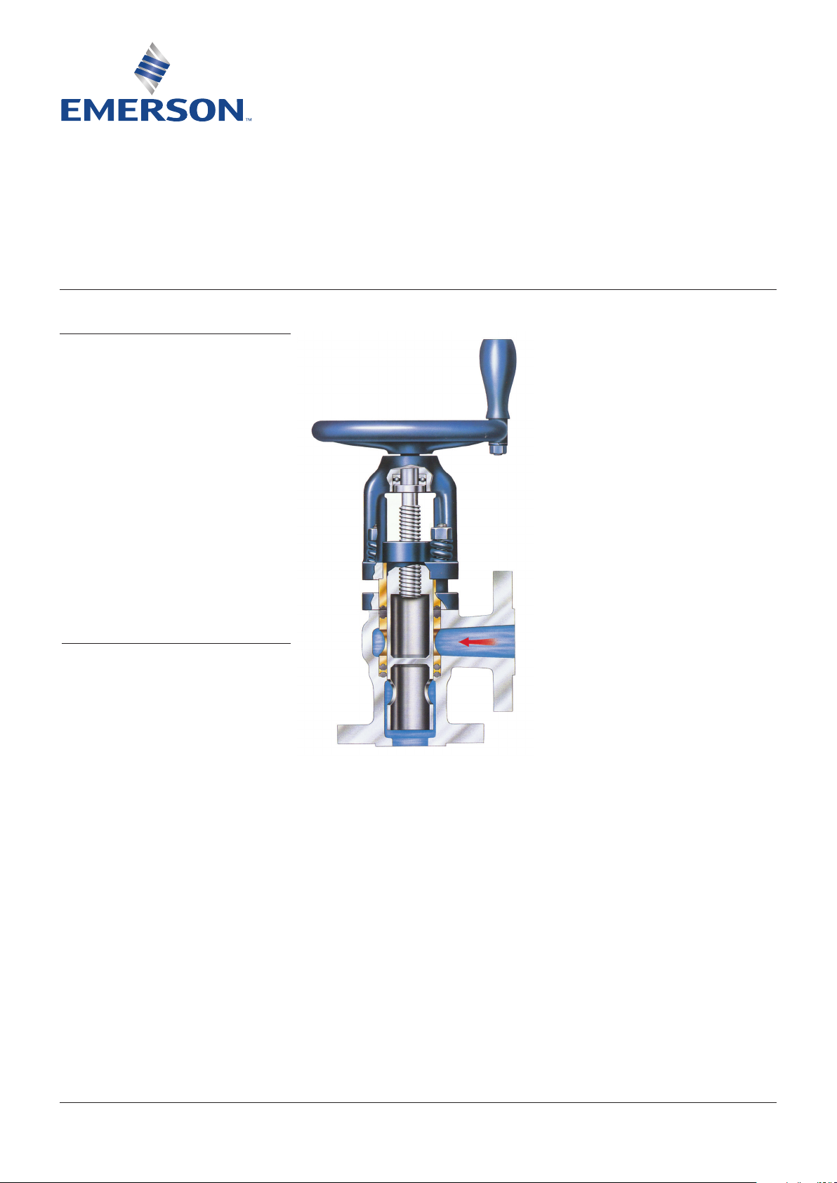
PRINCIPLE OF OPERATION
The seatles blow-off valve is a manually
operated sliding primarily for boiler blow-off
service where high temperature fluid,
containing dirt, sediment and scale, is
encountered.
When the valve is open (Fig. 2) the controlled
fluid passes through the ports in the plunger
(8) and lower gland (5) and discharges to the
valve outlet via the center of the plunger
assembly. In the closed position the shoulder
of the plunger assembly contacts the upper
gland (6). This feature provides additional
loading from the handwheel to compress the
packing rings (3) (4) and assure leak-tight
shut-off. Any packing relaxation during service
is accommodated by the heavy compression
springs (14) which provide a constant packing
load.
VALVE OPERATION
Open the valve quickly and fully. Never use this
valve to throttle the flow in the partly open
condition as this will reduce the packing life.
Close the valve in the same manner. Apply a
hard turn at the end of the valve travel. This
will assure that the plunger seats against the
upper gland which, in turn, will recompress
the packing rings.
In operating Yarway seatless valves in tandem,
the valve next to the boiler should be used as
the blowing valve, opened last and closed first.
The outside or sealing valve should be opened
first and closed last.
If a Yarway double tghtening valve is used in
tandem with a Yarway seatless valve, the
double tighteningvalve is placed next to the
boiler and is opened first and closed last. The
Seatless or outside valve is the blowing valve
and is opened last and closed first.
WARNING
Hot discharge from this product may cause severe
burns. Discharge must be piped away or directed
so that persons in the vicinity are not endangered.
This product must be isolated, vented and cool to
the touch before repairing or inspecting.
© 2018 Emerson. All Rights Reserved.Emerson.com/FinalControl VCIOM-03114 EN 18/10
YARWAY SEATLESS BLOW-OFF VALVES
Type b and Type c
MAINTENANCE AND ADJUSTMENT
Packing ring adjusment
Yoke nuts (15A) should be tightened at regular
intervals. The yoke springs (14) will maintain a
constant load on the packing. Packing rings
will relax slightly during use and an adjustment
may be required. To adjust the packing,
back the plunger off slightly by turning the
handwheel (do not allow flow to occur) and then
tighten the yoke nuts. Approximately ¼ to ½
turn should be sufficient. Reseat the plunger
against the upper gland.
NOTE:
If the valve has not been operated for a long period, the
packing nuts should be adjusted prior to blowing down
the boiler.
Lubrication
A fitting (2A) is provided on the yoke for
lubricating the ball thrust bearing (11) and the
stem collar. This fitting is compatible with an
Alemite No. 7585 gun. A high temperature
grease equivalent to Texaco Regal AFB2
should be used to lubricate this area. Stem
threads should be kept well lubricated. A good
grade of antiseize compound similar to NeverSeez NS165 should be used. Both of these
areas should be lubricated every six months.
Installation of packing rings
WARNING
This procedure should not be attempted unless all
pressure has been vented from the valve, and its
connecting lines, and the temperature of the valve
is at or near ambient.
Remove the stopscrew (10) then remove the
yoke nuts and springs. Turn the handwheel to
open the valve. This will raise the plunger. Turn
the handwheel to close the valve. This will raise
the yoke. Turn the yoke so that the holes and
studs are out of line and turn the handwheel to
open the valve. The plunger is thus withdrawn
from the valve.
Next, remove the glands and the old packing.
This can be done by using a Yarway gland and
packing puller or similar tool (Fig. 3) in the
following manner: Insert the tool until the
pawls engage the ports in the lower gland.
Tighten the nut on the top of the puller to draw
out the lower gland, upper packing and upper
gland. The lower packing can then be removed
using a hook tool. Care should be exercised,
however, so that the lower packing groove is
not damaged. Install new packing rings, (Fig. 4
or 5) glands and stopscrew in the body and
replace the yoke, with the plunger screwed all
the way up on the stem, in place and using the
yoke nuts pull down the yoke assembly. Next,
place the springs under the nuts and adjust as
previously described.
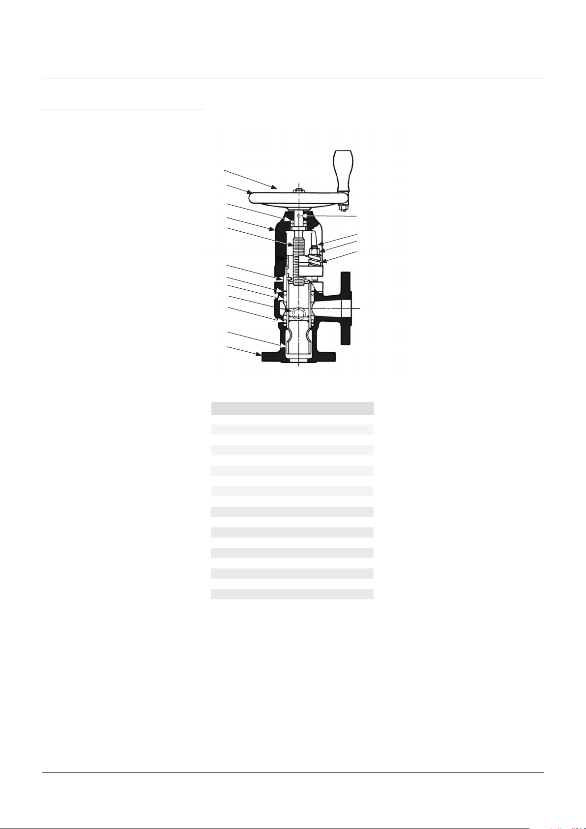
FIGURE 2
Type C angle valve
9A
12
11
2
9
6
4
5
10,10A
3
8
1
TYPE C ANGLE VALVE
Item Description
1 Body
2 Yoke
2A Lubrication fitting
3 Lower packing ring assembly
4 Upper packing ring assembly
5 Lower gland
6 Upper gland
8 Plunger assembly
9 Stem
9A Stem nut
10 Stop screw
10A Stop screw gasket
11 Rail thrust bearing (2 Type C; 1 Type B)
12 Handwheel
13 Extension lever (Type C only)
14 Yoke springs (4 per set)
15 Yoke studs (4 per set)
15A Yoke stud nuts (4 per set)
NOTE:
When ordering parts, use parts numbers and names
shown in table, specify size and type of valve, figure
number and operating pressure (see nameplate on
valve). Maintenance kits for Type B valves include
the following: cast iron valve, 250 psi: upper & lower
glands, packing set, springs, studs, nuts, stop screw,
stop screw gasket, cast steel valve, 300 psi & 400
psi: upper and lower glands, packing set, stem, ball
bearing, springs, studs, nuts, stop screw gasket.
2A
15
15A
14
2
 Loading...