

Emerson Yarway 9200 Series, Yarway ARC 9200 Series Installation And Maintenance Instructions Manual
YARWAY 9200 SERIES ARC® VALVES 2", 3" AND 4"
InstallatIon and maIntenance InstructIons
Before installation these instructions must be fully read and understood
OPERATION
Flow through the check valve overcomes the
spring force to open the main check valve
element. When the disc lifts in response to
an increase in main flow, the bypass flow is
decreased as the port openings in the disc stem
begin to close. Conversely, as the pump flow is
reduced, the check disc moves downward and
at a designated point starts to uncover the disc
stem ports allowing bypass flow to begin.
The sizing of the main check/trim is such that
the bypass flow starts before the main flow
drops below the minimum pump flow specified.
The combined main and bypass flows provide
a total greater than the minimum pump flow
requirement.
GENERAL
These sizes in the 9200 ARC® (Automatic
Recirculation Control) valve series are designed
to provide protection for low to moderate
pressure (ASME/ANSI 150 and 300 Class)
centrifugal pumps against overheating and
possible unstable operation during low load
periods. The valve functions simultaneously
as (1) a check valve - to prevent reverse flow
through the pump and as (2) a bypass control
valve - to maintain the minimum required
pump flow and provide pressure letdown.
Bypass flow enters the disc stem passage
through the slots and the round ports and
around the annulus in the bypass bushing. It
then continues through the bypass where the
helix element conditions the flow at the valve
bypass outlet. The recirculation flow rate is
controlled by the disc slot sizing. Occasionally
higher pressure applications may require the
use of a Back Pressure Regulator (BPR) in the
bypass line for proper pressure letdown.
Engineering doc. #972562 Rev. A
© 2017 Emerson. All Rights Reserved.valves.emerson.com VCIOM-03341-EN 17/05
YARWAY 9200 SERIES ARC® VALVES 2", 3" AND 4"
InstallatIon and maIntenance InstructIons
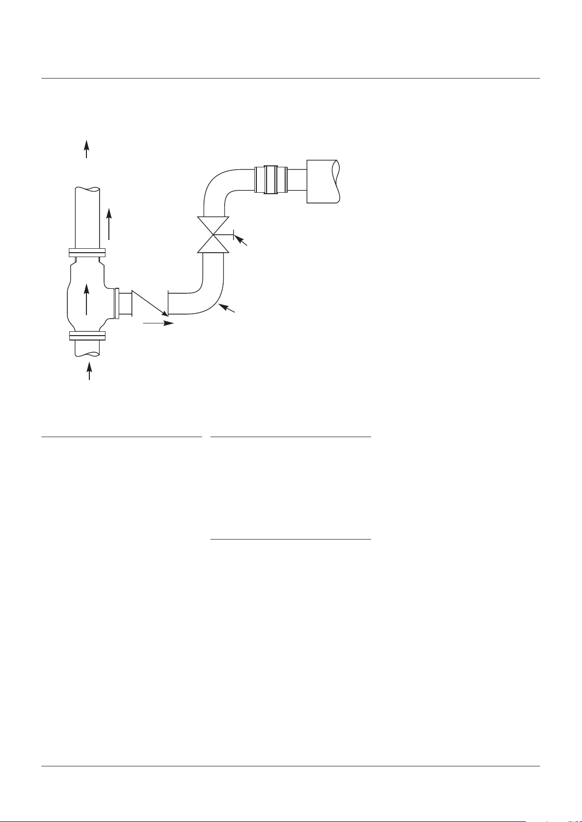
FIGURE 1
3 diameters straight pipe
minimum recommended
atvalve outlet
BPR
if required
To process
Main flow
Shut off valve
Optional
checkvalve
Long radius pipe
Bypass flow
bends typical
Receiver vessel
5 diameters straight pipe minimum
recommended at valve inlet
From pump
INSTALLATION (REFER TO FIGURE 1)
The 9200 Series valve is sized and configured
based on specifications provided by the user.
Make certain that these conditions are still
applicable. Changes in pressure, temperature,
normal main flow and minimum flow
requirements could result in unsatisfactory
performance. If operating conditions have
changed, contact Yarway; modifications
mayberequired prior to installation.
Remove all packing material. Place the valve
on wooden blocks with the flow arrow pointed
down. Push the disc from its seat and flush
away any packing materials with compressed
air or high pressure water. The disc should
move freely (against the spring load) through
the entire stroke length until contacting the
upper stop. This may not be practical on
larger sizes.
The valve may be installed with the main flow
direction either horizontal or vertically up.
Thedirection of bypass flow may be selected
tosuit the installation.
OPERATIONAL CHECK
When the valve is properly installed the
combined main and bypass flows should equal
or exceed that of the specified minimum pump
flow. If operational checks indicate a deviation
from the original specifications and field
adjustments are necessary, contact Yarway
for additional information.
VALVE MAINTENANCE
Except for periodic operational checks the
valve requires little maintenance. The disc
assembly, spring, bypass bushing and flow
conditioner should be inspected coincident
withother annual inspections. Make certain
that all pressure is relieved and the pipeline
is securedagainst pressurization before
attempting disassembly for inspection
purposes.
2
 Loading...