

Emerson YARWAY 460D3 Series, YARWAY 515D3 Series Instruction, Operation And Maintenance Manual
YARWAY SERIES 460D3 AND 515D3 INTEGRAL STRAINER HIGH PRESSURE DISC TRAPS
INSTRUCTION, OPERATION AND MAINTENANCE MANUAL
Before installation these instructions must be fully read and understood
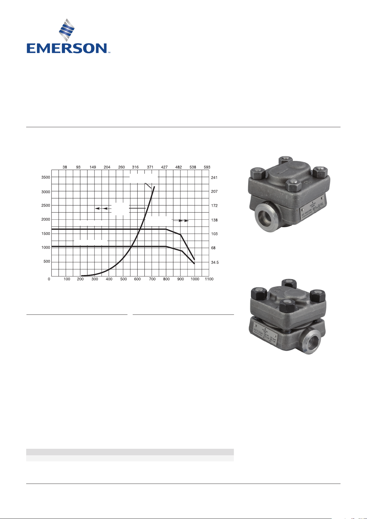
DESIGN PRESSURE/TEMPERATURE RATINGS
SERIES 460D3
MAX. TEMPERATURE (C)
SATURATION
CURVE
ALL
LIQUID
PHASE
SERIES 515D3
ALL
SUPERHEAT
MAX. PRESSURE, psi
SERIES 460D3
MAX. TEMPERATURE (F)
RATING
Disc traps operate from 150 psig to 1500 psig.
Operation at lower pressures may result in
reduced air handling properties, and low cycle
rates.
The maximum allowable back pressure outlet
is 80% of pressure at trap inlet, based on
absolute pressures.
MAX. PRESSURE, bar
SERIES 515D3
SERIES NUMBERS
To determine the size, series number, and
operating conditions rating, refer to the
nameplate on the trap body.
Suffix letter identification
SW Socket weld ends
FL Flanged ends (special option)
D3 Disc trap
SHELL PRESSURE/TEMPERATURE RATINGS
460D3 900 150 900
Trap operating conditions Maximum operating pressure (psig) Maximum operating temp. (°F)
515D3 1500 150 900
Emerson.com/FinalControl © 2017 Emerson. All rights reserved. VCIOM-09544-EN 19/05
YARWAY SERIES 460D3 AND 515D3 INTEGRAL STRAINER HIGH PRESSURE DISC TRAPS
INSTRUCTION, OPERATION AND MAINTENANCE MANUAL
INSTALLATION
Piping to and from the trap should be equal to
trap size or one size larger. Discharge line for
short runs equal to trap size; larger for long
runs. Avoid configurations that would cause
excessive back pressure.
Blow the System Out before installing the
trap. Frequent strainer blowdown or cleaning
is recommended on a new system. Conditions
will dictate frequency of blowdown in
normaloperation.
Valves-Use globe type (Yarway Welbond
®
)
for isolation strainer blow-down, or for test
(see Figure 1).
Bypasses not recommended except for critical
installations. If discharge is to a multi-station
or overhead return, put a swing check valve
in discharge line to prevent backflooding on
shutdown. Select a check valve suitable for the
application.
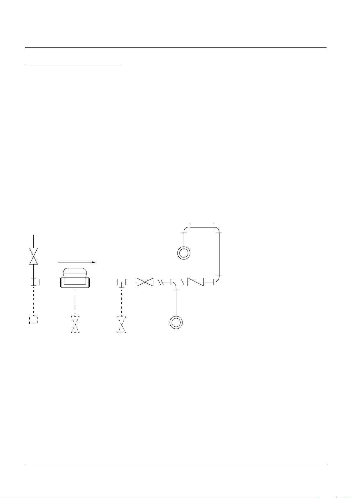
FIGURE 1
Locate Trap below outlet from equipment
(gravity flow). If trap must be above the drain
provide a 'U' or lift fitting at the bottom of the
riser before the trap (water seal). The trap may
be installed in a horizontal or vertical line or at
any angle so long as the discharge is downward
or horizontal.
Welding-Socket welding of this trap body to
the piping should be completed according to
applicable codes, standards, and procedures.
DO NOT make electrical welding connections
to the trap body or any other part of the trap
to prevent internal arcing. Electrical ground
should be made to the pipe and not the trap.
Equipment drain
Yarway Welbond shut off valve
Steam trap
Dirt leg
(optional)
Strainer blow-down (optional)
½ Yarway Welbond globe valve
Test valve (optional)
Yarway Welbond globe valve
Elevated return
Check valve
Return main
WARNING
Hot discharge from this product may cause severe burns. Discharge must be piped away or directed so
that persons in the vicinity are not endangered. This product must be isolated, vented and cool to the
touch before repairing or inspecting.
2

YARWAY SERIES 460D3 AND 515D3 INTEGRAL STRAINER HIGH PRESSURE DISC TRAPS
INSTRUCTION, OPERATION AND MAINTENANCE MANUAL
MAINTENANCE
Check bonnet nut torque after 48 hours
ofoperation.
1. For the best trap operation and maximum
service life, strainer screen should be
cleaned frequently. This can best be done by
using a blowdown valve connected to blowoff connection.
2. Periodically remove the bonnet and clean
and inspect the screen. This should be done
at least once a year and more frequently
if the trap is not fitted with a strainer
blowdown valve.
3. When cleaning the strainer it is
recommended that the trap be inspected
and working parts cleaned if necessary. In
the event of condensate drainage problems,
check before opening the trap whether
the trouble is due to a clogged line, valve
broken or in wrong position, or dirty strainer
requiring blowdown.
4. More frequent checks for proper trap
operation can be quickly made by one of the
following methods:
a. Observe the discharge from the trap
through the test connection-first closing
the downstream stop valve.
b. Hold screwdriver or metal rod against
base of cap. Listen for characteristic
clicking sound of valve as it opens and
closes.
c. Check temperature of the cleaned pipe
surface up and downstream of trap.
Use a touch pyrometer or temperature
sensitive crayon.
PARTS LIST
Item Quantity Description
1 1 Body
2 1 Bonnet
3* 1 Seat
4* 1 Cap, seat
5* 1 Disc
6* 1 Gasket, capsule
7* 1 Screen
8 4 Stud
9 4 Nut
10* 1 Gasket, bonnet
11* 1 Gasket, seat
* Renewal kit
DISASSEMBLY
1. Remove bonnet.
2. Remove seat capsule from bonnet. The
capsule is a clearance fit in the bonnet bore.
It may be necessary to insert a small rod in
the seat inlet port and extract the capsule
with a turning, pulling motion.
3. Inspect and clean all parts. If satisfactory,
reassemble trap. See page 4 for repair kit
installation and assembly.
If trap is remaining open continuously or not
operating at all:
• Strainer screen may be damaged or dirty
• Parts may be worn from service
• Dirt and scale may be lodged in internals
Disassemble and inspect the trap.
3

YARWAY SERIES 460D3 AND 515D3 INTEGRAL STRAINER HIGH PRESSURE DISC TRAPS
INSTRUCTION, OPERATION AND MAINTENANCE MANUAL
SERVICING
After disassembly, clean internal parts
with a cloth and non-corrosive solvent.
Replace the capsule, screen and gaskets for
best performance.
The capsule gasket is not furnished with the
repair kit and should be ordered separately.
If required, the trap capsule may be
disassembled by holding the cap in a vice with
soft copper or aluminum jaws, inserting a
short rod in the seat inlet port, and the seat
extracted with a twisting, pulling motion.
The sealing gasket will remain in the cap.
Inspect the disc and seat for dirt and wear.
Remove adhered dirt using a soft cloth and
non-corrosive solvent. If the seat and disc are
serviceable and capsule reassembly is desired,
remove the capsule gasket from the cap;
use care to avoid damage to the cap sealing
surface. Verify the gasket metal end caps have
been removed from the cap; reassemble the
capsule using a new gasket. The capsule can
then be placed in the trap.
An alternate method of capsule assembly is to
partially compress the gasket before placing
the capsule in the trap. The gasket may be
compressed by placing the capsule in an arbor
press, protecting the gasket and cap surfaces,
and applying sufficient load to reduce the space
between the cap and seat approximately 50%.
It is not necessary for the cap to contact the
seat. The space between seat an cap contact
will increase when load is removed, due to
gasket springback. The seated gasket holds the
parts together, and creates a single part that is
easily handled and simplifies trap assembly.
SPARE PARTS
To cover a one year service period, it is
recommended that spare parts be stocked as
follow:
Renewal kit - one (1) for every four (4) traps.
Minimum number of kits one (1) and sufficient
gaskets for trap inspection.
Other replacement parts
Conversion kit - consisting of (1) bonnet,
(1) capsule assembly, (1) screen, (1) seat to
body gasket, (1) bonnet gasket.
Steam trap figure no. Conversion kit part no.
460 A, B, C to 460D3 972401-04
515 A, B, C to 515D3 972376-03
Renewal kit - consisting of (1) capsule
assembly, (1) screen, (1) seat to body gasket, (1)
bonnet gasket.
Steam trap figure no. Renewal kit part no.
360D3 972401-02
515D3
Gaskets, 460D3 and 515D3
Bonnet gasket 965924-02
Seat gasket 965924-01
Capsule gasket 972400
REASSEMBLY
1.
Clean sealing surfaces and all internal parts.
2. Clean studs and nuts, lubricate studs and
nut faces with high temperature lubricant.
3. Push screen into body recess. Place capsule
in bonnet. With bonnet and seat gaskets in
place, lower bonnet over studs.
4. Replace bonnet nuts, hand tighten, then
tighten alternately to the torque listed.
BONNET NUT TORQUE VALUES
Figure no. ft·lbs (Nm)
460D3 65 - 70 (88 - 95)
515D3 110 - 130 (149 - 176)
4

YARWAY SERIES 460D3 AND 515D3 INTEGRAL STRAINER HIGH PRESSURE DISC TRAPS
INSTRUCTION, OPERATION AND MAINTENANCE MANUAL
NOTE
Any malfunction of this product must be reported to the service department.
Repare made to the product by unauthorized personnel will void the warranty.
Right to know laws and OSHA standard 29CFR (1910.1200)
Material Safety Data Sheets on the following Yarway products:
Valves, Steam traps and Strainers
The OSHA Hazard Communication Standard 29CFR 1910.1200, states that the standard does not
apply to “articles.” The standard defines an article as:
“A manufactured item formed to a specific shape or design for a particular use which does not
release or otherwise expose an employee to a hazardous chemical under normal conditions of use.”
The above named products fall within the definition of an “article”, no Material Safety Data Sheets
are available or are required. Our product is manufactured as an “end product.”
If the product is a weld end the following applies.
WARNING
Materials used in manufacture of Yarway products are considered in a stable condition when shipped.
However, under certain conditions purchasers could create potential hazardous conditions by their
future operations.
CAUTION
Welding, cutting, burning, machining or grinding of this product can generate toxic dust and fumes of
potentially hazardous ingredients. The dust or fumes can cause irritation of the respiratory tract, nose,
throat, skin and eyes. It may cause temporary or permanent respiratory disease in a small percentage
of exposed individuals. Use moderate ventilation when grinding or welding. Avoid breathing dust, fumes
or mist. Avoid prolonged skin contact with dust or mist. Maintain dust levels below OSHA and ACGIH
levels. Use protective devices. Wash hands thoroughly after contact with dust before eating or smoking.
Neither Emerson, Emerson Automation Solutions, nor any of their affiliated entities assumes responsibility for the selection, use or maintenance of any product.
Responsibility for proper selection, use, and maintenance of any product remains solely with the purchaser and end user.
Yarway is a mark owned by one of the companies in the Emerson Automation Solutions business unit of Emerson Electric Co. Emerson Automation Solutions, Emerson and
the Emerson logo are trademarks and service marks of Emerson Electric Co. All other marks are the property of their respective owners.
The contents of this publication are presented for informational purposes only, and while every effort has been made to ensure their accuracy, they are not to be construed
as warranties or guarantees, express or implied, regarding the products or services described herein or their use or applicability. All sales are governed by our terms and
conditions, which are available upon request. We reserve the right to modify or improve the designs or specifications of such products at any time without notice.
Emerson.com/FinalControl
5
 Loading...